Indel Webasto Marine Isotherm VE150 Installation And Usage Instructions
- Tipo
- Installation And Usage Instructions

Istruzioni per l’installazione e l’uso
Unità Refrigerante
VE150
I
Installaon and usage instrucons
Cooling Unit
VE150
EN
Installaons- und Wartungsanleitung
Bedienungsanleitung Kühleinheit
VE150
DE
Instrucons pour l’installaon et l’ulisaon
Unité Réfrigérante
VE150
FR
Instrucciones para la instalación y el uso
Unidad Refrigerante
VE150
ES


VE150 Cooling Unit
3
Prima di eeuare la messa in funzione leggere accuratamente questo manuale di istruzioni,
conservarlo e in caso di rivendita dell’apparecchio consegnarlo al cliente successivo.
AVVERTENZE
- La mancata osservanza delle indicazioni può causare danni a persone e apparecchi
- Non è ammesso l’impiego di questa apparecchiatura per altri ni rispeo a quelli descri in
questo manuale.
SICUREZZA GENERALE
- Far installare l’apparecchiatura solo da personale qualicato.
- Se l’apparecchiatura presenta danni visibili, evitare di meerla in funzione.
- L’apparecchiatura deve essere riparata solo da personale specializzato (centri Assistenza
Indel Webasto Marine), le riparazioni eeuate in modo non adeguato potrebbero causare
danni a cose o persone.
- Non aprire in nessun caso il circuito di rareddamento.
- Installare l’apparecchio in un posto asciuo, proteo da eventuali spruzzi d’acqua e riparato
dai raggi solari dire.
- Non collocare l’apparecchio nelle vicinanze di amme libere o altre fon di calore
(riscaldamento, raggi solari dire, forni a gas, etc.).
- Assicurarsi che l’unità refrigerante (compressore) sia sucientemente venlata.
- L’apparecchio deve essere conservato e/o installato lontano dalla portata dei bambini.
- Prima della messa in funzione dell’apparecchio, vericare se la tensione di esercizio e quella
della baeria corrispondono.
- Per il collegamento all’alimentazione elerica principale ulizzare sistemi di protezione e/o
interruore dierenziale (∆I 0,03 A).
- Se il cavo di allacciamento risulta essere danneggiato è necessario sostuirlo con un cavo
dalle stesse speciche tecniche (sezione e lunghezza).
- Per la pulizia generale dell’apparecchiatura non ulizzare mai detergen contenen
sostanze sabbiose, acide o solven.
- Proteggere l’apparecchiatura da pioggia ed umidità.
- Prima di collegare il carica baerie rapido, disconneere l’alimentazione principale
dell’apparecchiatura.
- Non toccare mai a mani nude eventuali cavi scoper e/o danneggia.
- Disconneere l’apparecchiatura dalla rete di alimentazione se non ulizzata per lunghi
periodi.
- Le baerie possono contenere liquidi acidi aggressivi e corrosivi, evitare che gli stessi
vengano a contao con occhi/pelle.

4
VE150 Cooling Unit
INSTALLAZIONE ED USO
L’apparecchio refrigerante Isotherm VE150 è progeato specicatamente per l’installazione all’intero di
un box appositamente realizzato per la refrigerazione e conservazione degli alimen, oppure può essere
impiegato per refrigerare un vano già esistente non ulizzato.
L’apparecchio è dotato di tu componen necessari per il suo montaggio, facilmente eseguibile senza
l’ulizzo di arezzature parcolari.
In fase di produzione viene caricato con il gas refrigerante idoneo e fornito pronto per l’ulizzo.
Per semplicare l’installazione, il sistema è diviso in 2 sezioni: gruppo condensatore e gruppo evaporatore.
Queste sezioni sono collegate assieme mediante un tubo essibile munito di aacchi rapidi che possono
essere facilmente collega e scollega ripetutamente senza alcuna perdita di refrigerante.
Quando una delle due par (gruppo condensatore o gruppo evaporatore) deve essere sostuita o
modicata, è necessario ripetere la procedura vuoto/ricarica del gas.
Il box di alloggiamento dell’evaporatore, deve essere ben isolato. Usare una schiuma poliuretanica o
pannelli isolan dalle seguen sezioni consigliate:
Volume Box (lt) Spessore Materiale Isolante
L ≤ 100 30 mm
100 < L ≤ 150 50 mm
150 < L ≤ 200 80 mm
200 < L ≤ 250 100 mm
La capacità della baeria deve essere di almeno 75Ah per consenre un correo funzionamento
dell’unità.
Tu i disposivi di alimentazione elerica devono essere mantenu sempre in buone condizioni.
Nota: La capacità rareddante dell’unità è determinata dalla resistenza collegata tra il morseo “T” della
centralina e un polo del termostato. Per volumi superiori ai 150 litri o per box/vani realizza con materiale
a basso potere isolante termico, la resistenza deve essere presente. Per volumi inferiori ai 150 litri la
resistenza deve essere omessa. Vedi schema elerico.
INSTALLAZIONE DEL GRUPPO CONDENSATORE
Il gruppo condensatore deve essere installato in posizione orizzontale, può funzionare costantemente
no ad una inclinazione massima di 30°. Deve essere installato in un ambiente ben venlato e riparato da
eventuali spruzzi d’acqua, se l’apparecchio viene installato in uno spazio ristreo l’areazione deve essere
migliorata mediante fori di venlazione del diametro di 8 cm, uno situato sulla parte superiore ed uno
sulla parte inferiore della zona di installazione. Il gruppo deve essere ssato araverso i quaro fori situa
sulla basa del supporto del gruppo condensatore. Vedi gura a lato.
Posizionare il gruppo condensatore vicino alla postazione nella quale si prevede di installare il gruppo
evaporante, in modo da non superare la lunghezza del tubo di collegamento (2mt circa).

VE150 Cooling Unit
5
CONNESSIONI ELETTRICHE
L’unità eleronica deve essere collegata direamente alla baeria o all’interruore principale,
protea da sintemi di sicurezza: fusibile, interruori automaci o interruori dierenziali nel caso
di alimentazione alternata. Il fusibile per la connessione elerica in corrente connua deve essere
almeno di 15A per tensione 12Vdc e almeno 7,5A per tensione 24Vdc.
E’ molto importante ulizzare i cavi di sezione correa per l’alimentazione principale.
La sezione dei cavi minima, in proporzione alla distanza tra l’unità e la baeria, e indicata in tabella:
Sezioni Cavo mm² Lunghezza Max (mt) 12Vdc Lunghezza Max (mt) 24Vdc
2,5 0 – 2,5 0 – 5
4 2,5 – 4 5 – 8
6 4 – 6 8 – 12
Per evitare perdite di tensione e potenza, il cavo deve essere il più corto possibile e non essere
interroo.
L’unità elerica include una protezione eleronica contro l’inversione di polarità. Per proteggere la
baeria l’unità si spegne automacamente quando la tensione non’è più suciente.
12 Vdc 24Vdc
Cut-Out Cut-In Max Cut-Out Cut-In Max
9,6V 10,9V 17V 21,3V 22,7V 31,5V
Se l’unità refrigerante è alimentata con un collegamento alla terra con una rete a corrente alternata
(100-240 Vac) è necessario inserire un interruore dierenziale di protezione tra la rete elerica e
l’unità refrigerante (∆I 0,03 A).

6
VE150 Cooling Unit
SCHEMA ELETTRICO
AC
DC

VE150 Cooling Unit
7
INSTALLAZIONE DEL GRUPPO EVAPORANTE
L’evaporatore deve essere posizionato nella parte più alta all’interno del box/vano in
posizione vercale. Vedi gura a lato.
Pracare un foro del diametro di 30mm nella parete del box/vano per il passaggio
del tubo essibile con gli aacchi rapidi.
Prima di installare il gruppo evaporante, svolgere completamente il tubo
mantenendo sempre le coperture di protezione sugli aacchi rapidi nché non si
eeuerà il collegamento con la parte condensatrice.
Partendo dall’interno del box/vano, far passare il tubo con gli aacchi rapidi
araverso il foro precedentemente eeuato no a raggiungere il gruppo condensatore facendo
aenzione a non piegare a schiacciare il tubo. Il tubo non può essere accorciato perché carico di gas
refrigerante. Il tubo in eccesso può essere avvolto a spirale con un raggio di curvatura minimo di 10cm
e deve essere ssato per impedire la generazione di vibrazioni e rumorosità.
Sollevare il coperchio superiore del carter, ssare il gruppo evaporante araverso gli apposi fori
predispos e sigillare l’apertura creata per il passaggio del tubo con sigillante o schiuma.
Chiudere il coperchio superiore mediante n. 4 rive a scao forni in dotazione.
Inserire la manopola del termostato fornita in dotazione.
COLLEGAMENTO MECCANICO/ELETTRICO
Gli aacchi rapidi possono essere a questo punto connessi come segue:
collegare prima il giunto rapido con il tubo capillare e successivamente quello con il tubo di aspirazione
ruotando solo il dado dell’aacco femmina, avvitando gli aacchi no a bauta della leatura quindi
stringerli saldamente ulizzando utensili idonei per 1/6 di giro o 60° di rotazione massima.
Non geare le coperture di protezione dei giun rapidi se fosse necessario riposizionare
l’apparecchiatura, in tal caso gli aacchi possono essere riaper senza che fuoriesca il gas refrigerante
e immediatamente devono essere prote dai loro tappi protevi.
Successivamente collegare le connessioni eleriche come da schema elerico. Vedi schema elerico.

8
VE150 Cooling Unit
AVVIAMENTO
Eeuare una prova di funzionamento dell’apparecchiatura ruotando in senso orario la manopola
del termostato. Il compressore deve avviarsi entro pochi secondi. Controllare che la ventola di
rareddamento del condensatore e quella di distribuzione del gruppo evaporante siano in funzione.
Dopo qualche minuto dall’avvio, il gruppo evaporante inizierà a rareddarsi producendo aria fredda
dalla parte inferiore.
La temperatura è regolabile tramite l’apposita manopola di regolazione, con una scala valori che va da
0 a 7, dove 7 è il valore di massima produzione di freddo e 0 è il valore di stop/spegnimento.
MANUTENZIONE
L’apparecchio refrigerante completo può rimanere sull’imbarcazione durante l’inverno, per mantenere
l’ecienza rimuovere periodicamente la polvere che può essersi accumulata sul condensatore.
NOTE GENERALI
L’unità refrigerante è costruita per refrigerare box/vani a alla conservazione di alimen, un uso
improprio e diverso è da considerarsi pericoloso ed il costruore declina ogni responsabilità per
eventuali danni.
Imballaggio: Lo smalmento dell’imballaggio e dell’unità deve essere eeuato in accordo con le leggi
ambientali vigen nel luogo di ulizzo. Assicurarsi che il prodoo sai smalto correamente.
Gli alimen inseri nel Box/Vano refrigerato dovranno essere mantenu in contenitori ada agli
alimen o nella confezione originale.

VE150 Cooling Unit
9
Problema
Movo Possibile Soluzio-
ne/Controllo
Soluzione Note
Unità Venlata
L’Unità refrige-
rante non parte
– Unità nuova
La tensione dell’ali-
mentazione principale
è troppo bassa
L’unità non’è con-
nessa o sono inver-
te le polarità
Controllare connes-
sione cavi
Controllare la se-
zione dei cavi tra la
baeria e la scheda
eleronica
Controllare la
correa tensione
sulle connessioni
dell’unità elero-
nica, la tensioned
eve essere tra
10,5V e 13,5V per
baeria 12V e tra
21V e 27V per
baeria 25V.
Ricaricare la baeria
– se la baeria è più
vecchia di 3/4 anni
potrebbe essere ne-
cessario sostuirla!
I cavi sono ossida Sostuire i cavi
Termostato Il termostato non’è
connesso
Controllare la connes-
sione del termostato
e dell’unità eleronica
Il termostato è
roo!
Eseguire un ponte
tra C e T sull’unità
eleronica e con-
trollare se il com-
pressore si avvia
Sostuire il termo-
stato
Unità eleronica
difeosa (caso raro)
Esguire un ponte
tra le connessioni
C e T sull’unità
eleronica. L’unità
non si avvia no a
che il voltaggio è
correo.
Sostuire l’unità
eleronica
L’unità lavora per un
tempo limitato
Il condensatore
non ha la sucien-
te venlazione
Rimuovere l’unità
dalla sua postazione
e riavviarla, se l’unità
lavora correamente
aumentare la ven-
lazione
Trouble Shoong

10
VE150 Cooling Unit
Problema
Movo Possibile Soluzio-
ne/Controllo
Soluzione Note
L’unità lavora per
qualche secondo
– unità nuova
L’unità lavora per
meno di 0,5 sec.
Troppo gas caricato Rimuovere il gas in
eccesso dall’unità.
La pressione del gas
potrebbe dipendere
dalla temperature. In
circostanze normali
la pressione interna
potrebbe raggiungere
i 3,5 bar con tempe-
rature comprese tra i
20°-25°C.
L’unità è bloccata
tra il compressore
ed il condensatore
Aenzione situa-
zione pericolosa, il
problema può essere
risolto da un Tecnico
specializzato. Non c’è
pericolo per le perso-
ne ed il sistema.
Informazioni deagliate
posso essere richieste se
necessario.
L’unità lavora no a
2 sec.
Guaradare la sezio-
ne "L'unità lavora
per qualche secon-
do - Unità nuova"
L’unità lavora da 3 a
5 sec.
Ventola difeo-
sa – scollegare i
cavi della ventola
e controllare se
l’unità lavora
Sostuire la ventola
L’unità lavora ma
non raredda –
Unità nuova
Poco gas presente nel
sistema
Controllare se i
conneori rapidi
sono len o troppo
stre
Se i conneori sono
len, avvitarli a mano
no che è possible
dunque ulizzare un
utensile per connua-
re no ad un quarto
di giro (Massimo). Se
sono troppo stre,
sostuirli.

VE150 Cooling Unit
11
Problema
Movo Possibile Soluzio-
ne/Controllo
Soluzione Note
Unità nuova
Perdita di gas
1. Il consumo è <
del normale.
2. La pressione sulla
valvola di carica è <
0 quando il sistema
lavora.
3. La pressione sul-
la valvola di carica è
< 1,5 bar quando il
Sistema è spento
Chiudere la perdita
tramite saldatura
quando possibile o
rimuovere le par
forate.
Meere il Sistema soo
pressione con max. 5bar di
Azoto, ricercare la perdita con
il cercafughe.
Presenza di umidità
all’interno del capilla-
re dell’evaporatore
1. Il consumo è <
20% del normale
2. La pressione
sulla valvola di
carica è < di 0
quando il Sistema è
in funzione
3. La pressione sul-
la valvola di carica
è < 1,5 quando il
Sistema è spento
Spegnere il Sistema,
aspeare 5 min.,
quando il capillare si è
riscaldato riaccendere
il sistema, controllare
se si ripresenta lo
stesso problema. Se la
pressione si manene
soo lo 0, riscaldare
il capillare quando il
sistema è acceso. Se la
pressione si manene
soo lo 0 è necessario
inviare l’unità in labo-
ratorio.
Maggiori informazioni posso
essere richieste se necessario
Presenza di umidità
all’interno del cabinet
L’umidità all’interno
del bauleo può
passare araverso
la guarnizione
o I fori dei tubi
presen nel bau-
leo – presenza di
ghiaccio aorno
all’evaporatore
Guardare dove il
ghiaccio è più spesso,
normalmente l’umi-
dità si presenta in
questo punto
Riposizionare la guar-
nizione modellandola
manualmente, se
non’è possible uliz-
zare una moderata
sorgente di riscalda-
mento.
Sostuire la guarni-
zione dove possibile o
la porta
Troppo gas caricato
nel sistema
Basse prestazio-
ni – consumo
leggermente più
alto e presenza di
ghiaccio su I tubi
tra l’evaporato ed il
compressore
Rimuovere poco gas
alla volta araverso
la valvola di carica e
controllare la pres-
sione all’interno del
sistema

12
VE150 Cooling Unit
Problema
Movo Possibile Soluzio-
ne/Controllo
Soluzione Note
L’unità non si
avvia – Unità
funzionava corret-
tamente
L’alimentazione
generale è troppo
bassa
Connessione
elerica
Controllare
connessione elerica
Controllare la
tensione
I cavi sono ossida
Termostato Termostato difet-
toso!
Unità eleronica
difeosa
Tuo è installato
correamente, carica
gas correa, il sistema
non raredda corret-
tamente (caso raro)
Il consumo eleri-
co è leggermente
incrementato e la
pressione all’inter-
no del Sistema è
correa
Sostuire il compres-
sore
L’unità lavora per
qualche secondo
- Unità funzionava
correamente
L’unita lavora ma
non raredda –
Unità nuova
L’unità funziona in
connuazione
Il cabinet è troppo
grande
Controllare le
dimensioni del
cabinet e la capa-
cità massima di
rareddamento
dell’unità. L’unità
installata è quella
correa?
Avete l’unità errata
per il Vostro biso-
gno!!!
Il termostato non’è
installato sull’evapo-
ratore o installato in
posizione errata
Controllare se il
sensore del termo-
stato è installato
sull’evaporatore o
in una posizione
non correa
Posizionare il sensore
nella correa sede
Umidità presente
all’interno del cabinet
L’umidità può
penetrare all’in-
terno del cabinet
araverso la
guarnizione o I fori
per il passaggio
dei tubi. Ghiaccio
presente aorno
all’evaporatore
Cercare dove l’umidi-
tà penetra araverso
del cabinet

VE150 Cooling Unit
13
SICUREZZA
Non ulizzare l’apparecchiatura in caso di danni visibili, sia meccanici che elerici.
Non aprire mai il circuito refrigerante, tranne i giun ad accoppiamento rapido se sono del po auto-
sigillante e concepi a tale ne.
Vericare che la venlazione del compressore non sia bloccata. Se è presente un carica baerie, questo
deve essere connesso alla baeria e mai direamente all’unità refrigerante.
SPECIFICHE TECNICHE
Alimentazione DC: 12/24 VDC
Assorbimento DC: 6/3 A
Alimentazione AC: 100/240 VAC
Assorbimento AC: 0,7 A
Consumo Energeco Medio: 500 W/24h
Compressore: BD35F
Refrigerante: R134a
Capacità Refrigerante: Fino a 250 Litri
Fusibili DC: 15 A - 12 VDC / 7.5A - 24 VDC
Int. Aut. Di: 6A VAC (∆I 0.03 A)

14
VE150 Cooling Unit
Before starng up the unit, read this instrucon manual carefully, store it and pass it on the next
customer if the unit is resold.
WARNINGS
- Failure to follow instrucons may cause damage and/or injury
- This unit may not be used for purposes other than those described in this manual.
GENERAL SAFETY
- The unit must only be installed by qualied personnel.
- If the unit shows visible signs of damage, do not operate it.
- The unit must only be repaired by specialised personnel (Indel Webasto Marine Service
Centres). Repairs performed inadequately could cause damage and/or injury.
- Under no circumstances open the cooling circuit.
- Install the unit in a dry place, protected from any splashes of water and direct sunlight.
- Do not place the unit near naked ames or other heat sources (heang, direct sunlight, gas
ovens etc.).
- Ensure that the cooling unit (compressor) is suciently venlated.
- The unit must be stored and/or installed out of reach of children.
- Before operang the unit, ensure that the operang voltage and the baery voltage match.
- In order to connect to the main electricity supply, use protecon systems and/or a circuit
breaker (∆I 0.03 A).
- If the connecng cable is damaged, it must be replaced with a cable that has the same
technical specicaons (cross-secon and length).
- For general cleaning of the unit, never use detergents containing sandy substances, acids or
solvents.
- Protect the unit from rain and moisture.
- Before connecng the quick charger, disconnect the main power supply to the unit.
- Never touch any exposed and/or damaged wires with bare hands.
- Disconnect the unit from the mains when not in use for long periods.
- The baeries may contain aggressive acidic and corrosive liquids. Ensure these do not come
into contact with eyes/skin.

VE150 Cooling Unit
15
INSTALLATION AND USE
The Isotherm VE150 cooling unit is specically designed to be installed inside a box that has been
specially made for chilling and storing food, or can be used to chill a compartment that already exists
but is not in use.
The unit is equipped with all the components necessary for its assembly, which is easy and does not
require specic tools.
During the producon stage, it is loaded with the appropriate refrigerant and delivered ready for use.
To simplify installaon, the system is divided into 2 secons: the condenser unit and the evaporator
unit.
These secons are connected together via a hose equipped with quick couplings that can be easily
connected and disconnected repeatedly without any loss of refrigerant.
When one of the two parts (condenser unit or evaporator unit) must be replaced or modied, the gas
emptying/recharging procedure must be repeated.
The box housing the evaporator must be well insulated. Use a polyurethane foam or insulaon panels
with the following recommended cross-secons:
Box Volume (l) Thickness of Insulaon Material
L ≤ 100 30 mm
100 < L ≤ 150 50 mm
150 < L ≤ 200 80 mm
200 < L ≤ 250 100 mm
The baery capacity must be at least 75 Ah to enable correct unit operaon.
All electrical power supply devices must always be kept in good condion.
N.B. The cooling capacity of the unit is determined by the resistor connected between the terminal “T”
on the control unit and one pole of the thermostat. For volumes greater than 150 litres or for boxes/
compartments made using material with low thermal insulaon, the resistor must be present. For
volumes less than 150 litres, the resistor should be omied. See the wiring diagram.
INSTALLING THE CONDENSER UNIT
The condenser unit must be installed horizontally, and can operate constantly at a maximum gradient
of 30°. It must be installed in a well-venlated environment, protected from splashes of water. If the
unit is installed in a conned space, venlaon should be improved by creang venlaon holes with
a diameter of 8 cm, one located on the top and
one on the boom of the installaon area. The unit
must be secured through the four holes situated on
the condenser unit support base.
See the gure on the right.
Place the condenser unit near the locaon where
you plan to install the evaporator unit, so as not to
exceed the length of the connecng hose (about
2 m).

16
VE150 Cooling Unit
ELECTRICAL CONNECTIONS
The electronic unit must be connected directly to the baery or the main switch, protected by safety
systems: fuses, automac switches or circuit breakers in the case of AC power. The fuse for the direct
current electrical connecon must be at least 15 A for 12 VDC and at least 7.5 A for 24 VDC.
It is very important to use cables with the right cross-secon for the main power supply.
The minimum cross-secon of the cables, in proporon to the distance between the unit and baery, is
shown in the table:
Cable cross-secon (mm²) Max length (m) 12 VDC Max length (m) 24 VDC
2.5 0 – 2.5 0 – 5
4 2.5 – 4 5 – 8
6 4 – 6 8 – 12
To avoid loss of voltage and power, the cable must be as short as possible and not be interrupted.
The electrical unit includes electronic protecon against polarity reversal. To protect the baery, the
unit shuts o automacally when the voltage is no longer sucient.
12 VDC 24 VDC
Cut-Out Cut-In Max Cut-Out Cut-In Max
9.6 V 10.9 V 17 V 21.3 V 22.7 V 31.5 V
If the cooling unit is supplied with a connecon to earth with an AC network (100-240 VAC), it is
necessary to insert a protecve circuit breaker between the electrical mains and the cooling unit (∆I
0.03 A).

VE150 Cooling Unit
17
WIRING DIAGRAM
AC
DC

18
VE150 Cooling Unit
INSTALLING THE EVAPORATOR UNIT
The evaporator must be placed at the top inside the box/compartment in an upright
posion. See the gure on the right.
Drill a hole with a 30 mm diameter in the wall of the box/compartment so that the
hose with the quick couplings can pass through.
Before installing the evaporator unit, fully extend the hose, keeping the protecve
covers on the quick couplings unl connecon is made with the condenser part.
Starng from inside the box/compartment, pass the hose with the quick couplings
through the hole drilled beforehand, unl reaching the condenser unit, being careful
not to bend or crush the hose. The hose cannot be shortened as it is full of refrigerant. The excess hose
can be coiled with a minimum bend radius of 10 cm and must be secured to prevent vibraon and
noise being generated.
Li the top lid of the casing, secure the evaporator unit through the appropriate holes and seal the
opening created by the passage of the hose with sealant or foam.
Close the top cover with the 4 snap-in rivets provided.
Insert the supplied thermostat knob
MECHANICAL/ELECTRICAL CONNECTION
The quick couplings can be connected at this point as follows:
rst connect the quick joint to the capillary hose and then the laer to the sucon hose, turning the
female coupling unit only, ghtening the couplings unl reaching the end of the threads then securing
them ghtly using suitable tools for 1/6 of a revoluon or 60° maximum rotaon.
Do not discard the protecve covers on the quick joints if it is necessary to reposion the unit, as the
couplings can be reopened without the refrigerant coming out and must be protected immediately
using their protecve caps.
Then connect the electrical connecons as shown in the wiring diagram. See the wiring diagram.

VE150 Cooling Unit
19
START-UP
Test the operaon of the unit by turning the thermostat knob in a clockwise direcon. The compressor
must start up within a few seconds. Check that the condenser cooling fan and the evaporator unit
distribuon fan work correctly. A few minutes aer start-up, the evaporator unit will begin to cool
down, producing cold air from the boom.
The temperature can be adjusted using the control dial, with a scale with values ranging from 0 to 7,
where 7 is the maximum cold producon value and 0 is the stop/o value.
MAINTENANCE
The complete cooling unit can remain on the boat during the winter. To ensure it remains ecient,
periodically remove any dust that accumulates on the condenser.
GENERAL NOTES
The cooling unit is built to cool boxes/compartments designed for storing food. Improper use or any
other use is considered dangerous and the manufacturer disclaims any liability for damage or injury.
Packaging: The packaging and the unit must be disposed of in accordance with applicable
environmental laws in the place of use. Ensure that the product is disposed of properly.
The foods inserted in the cooled box/compartment must be kept in containers suitable for use with
food or in the original packaging.

20
VE150 Cooling Unit
Trouble Shoong
Problems
Reasons Possible Issue /
Check
Soluon Notes
Air cooled
The Cooling Unit
does not start -
the Unit is new
The main supply volt-
age is too low
The unit is not
connect or wrong
polarity
Check the wire con-
necon
Check the secon
of wires between
baery and elec-
tronic unit
101N0210.pdf
Check the voltage
on the connecon
right before the
Electronic Unit, the
voltage must be
between 10.5 V to
13.5 V for baery
at 12 VDC and 21
to 27 for baery at
24 VDC
Recharge the baery -
If the baery is older
than 3 or 4 years it
could be necessary to
replace it!
The wires are
oxidized
Replace the wires
Thermostat The thermostat is
not connected
Check the correct
connecon of the
thermostat on the
electronic unit and on
the thermostat.
Thermostat is
broken!
Bridge C and T con-
necons, on the
electronic unit.
The unit works.
Replace the ther-
mostat
Faulty electronic Unit
(rare case)
Bridge C and T con-
necons, on the
electronic unit.
The unit does not
start even if the
voltage is correct.
Replace the electronic
unit
Cooling Unit works
for a short period
of me
Not enough ven-
laon around the
condenser
Remove the fridge
from its place and
turn it on, if it keeps
cooling, improve the
venlaon!

VE150 Cooling Unit
21
Problems
Reasons Possible Issue /
Check
Soluon Notes
The Cooling Unit
works for few
seconds - the Unit
is new
It works <0.5 sec. Too much gas Remove some gas
from the unit. In this
situaon experience
is very important,
gas pressure may
vary depending on
temperature. Under
normal circumstances
internal pressure is
up to 3.5 bar with
temperature between
20-25°C
The unit is blocked
between compres-
sor and condenser
Warning, dangerous
situaon,
issue can be solved by
a skilled technician.
There is no actual
danger for people or
system.
More detailed info can be
requested if needed.
It works up to 2 sec. See “The Cooling
Unit works for few
seconds - the Unit
is new” secon
It works from 3 up to
5 sec.
Faulty Fan - discon-
nect wire of fan
and check if the
unit works
Replace the fan.
The Cooling Unit
works but it is not
cooling -
The Unit is new
Too low or no gas in
the system
Check if quick
couplings are well
ghtened.
Tight quick couplings
as much as possible
by hand, then use
tools to ght them
up to one quarter of
a turn

22
VE150 Cooling Unit
Problems
Reasons Possible Issue /
Check
Soluon Notes
The Unit is new
Gas Leakage
1. The electrical
consumpon is less
than normal
2. The pressure
on charge valve is
lower than 0 bar
(0 psi) when the
system works
3. The pressure on
charge valve is less
of 1.5 bar (21 psi)
when the system
is o
Where it is possible
close the leak with
welding or remove the
part where is the hole.
Put the system on pressure
with nitrogen gas max 5 bars
(70 psi), search the leakage
with liquid leak detector or
electronic nose for R134a
Presence of humidity
inside the capillary in
the evaporator.
1. The electrical
consumpon is
20% less than
normal.
2. The pressure
on charge valve is
lower than 0 bar
(0 psi) when the
system works
3. The pressure on
charge valve is less
of 1.5 bar (21 psi)
when the system
is o
Switch o the system,
wait about 5 minutes,
then heat up the capil-
lary, than turn on the
system, check again
from the beginning. If
pressure keeps going
under 0 bar, heat up
the capillary while the
system is on.
If pressure keeps
going under 0 bar, it
is necessary to bring
the unit back to the
laboratory.
More detailed info can be
requested if needed.
Presence of Humidity
inside the cabinet
Humidity gets
inside the cabinet
by passing through
the gasket or pipes
hole through the
cabinet. /
Ice presence all
over evaporator
Look where the ice is
thicker, usually humid-
ity gets in on that side.
Put back in place the
gasket, by modelling
it by hand, if it is not
possible by using mod-
erate heat source
Replace the gasket
where it is possible or
the door.
Too much gas Low performance
- a bit higher con-
sumpon and pres-
ence of ice on pipe
between evapora-
tor and compressor.
Remove gas a bit at a
me, check how pres-
sure works inside the
system.

VE150 Cooling Unit
23
Problems
Reasons Possible Issue /
Check
Soluon Notes
The Cooling Unit
does not start -
the Unit worked
The main supply
voltage is too low
Electrical
connecon
Check the wire
connecon
Check the voltage
The wires are
oxidized
Thermostat Thermostat is
broken!
Faulty electronic Unit
Everything is well
installed, gas inside
the system, no cool at
all (rare case)
Power consump-
on greatly in-
creased, constant
pressure in the
system
Replace the com-
pressor
The Cooling Unit
works for few
seconds - the Unit
worked
The Cooling Unit
works but it is not
cooling -
The Unit is new
The Cooling Unit
keeps working
The cabinet is too big Check the cabinet
dimension and
compare it to the
maximum cooling
capacity of the
unit.
Is the correct unit
installed in the
cabinet?
You have wrong cool-
ing unit!!!
Thermostat not in-
stalled on the evapo-
rator or installed in
the wrong posion
Check if the probe
is installed on the
evaporator or if
it is in a dierent
socket
Place the probe in the
appropriate socket
Humidity inside the
cabinet
Humidity gets
inside the cabinet
by passing through
gasket or pipes
hole through the
cabinet.
Ice presence all
over evaporator
Find where humidity
gets inside from.

24
VE150 Cooling Unit
SAFETY
Do not use the unit if there is visible damage, be it mechanical or electrical.
Never open the cooling circuit, except for the quick coupling joints if they are self-sealing and designed
for this purpose.
Check that compressor venlaon is not blocked. If there is a baery charger, it must be connected to
the baery and never directly to the cooling unit.
TECHNICAL DATA
DC power supply: 12/24 VDC
DC absorpon: 6/3 A
AC power supply: 100/240 VAC
AC absorpon: 0,7 A
Average power consumpon: 500 W/24h
Compressor: BD35F
Refrigerant: R134a
Refrigerant capacity: Up to 250 litres
DC fuses: 15 A - 12 VDC / 7.5A - 24 VDC
Circuit breaker: 6A VAC (∆I 0.03 A)

VE150 Cooling Unit
25
Avant d’eectuer la mise en foncon lire aenvement ce manuel d’instrucons, le conserver et en
cas de revente de l’appareil le remere au client successif.
AVERTISSEMENTS
- La non-observance des indicaons peut provoquer des dommages aux personnes et aux
appareils
- L’emploi de cet appareil pour des usages qui sont diérents de ceux décrits dans ce manuel
est interdit.
SECURITE GENERALE
- Faire installer l’appareil uniquement par du personnel qualié.
- Si l’appareil présente des dommages visibles, éviter de le mere en service.
- L’appareil doit être réparé uniquement par du personnel spécialisé (centres d’Assistance
Indel Webasto Marine), les réparaons eectuées de façon non-conforme pourraient
causer des dommages aux personnes et aux appareils.
- Ne jamais ouvrir le circuit de refroidissement.
- Installer l’appareil dans un endroit sec, protégé d’éventuelles projecons d’eau et à l’abri
des rayons du soleil directs.
- Ne pas installer l’appareil près de ammes libres ou d’autres sources de chaleur (chauage,
rayons du soleil, fours à gaz, etc.).
- S’assurer que l’unité réfrigérante (compresseur) est susamment venlée.
- L’appareil doit être conservé et/ou installé loin de la portée des enfants.
- Avant la mise en foncon de l’appareil, vérier si la tension d’exercice et celle de la baerie
correspondent.
- Pour le branchement à l’alimentaon électrique uliser des systèmes de protecon et /ou
un interrupteur à courant diérenel (∆I 0,03 A).
- Si le câble de branchement est endommagé il faut le remplacer par un câble ayant les
mêmes spécicaons techniques (secon et longueur).
- Pour le neoyage de l’appareil ne jamais uliser de détergents contenant des substances
grumeleuses, des acides ou des solvants.
- Protéger l’appareil de la pluie et de l’humidité.
- Avant de brancher le chargeur de baerie rapide, débrancher l’alimentaon principale de
l’appareil.
- Ne jamais toucher à mains nues des câbles éventuellement dénudés et/ou endommagés.
- Débrancher l’appareil du réseau d’alimentaon lorsqu’on ne l’ulise pas pendant de
longues périodes.
- Les baeries peuvent contenir des liquides acides agressifs et corrosifs, éviter qu’ils
n’entrent en contact avec les yeux, la peau.

26
VE150 Cooling Unit
INSTALLATION ET EMPLOI
L’appareil réfrigérant Isotherm VE150 est conçu spécialement pour l’installaon à l’intérieur d’un
core réalisé spécialement pour la réfrigéraon et la conservaon des aliments, ou pour être ulisé
pour refroidir un comparment déjà existant non ulisé.
L’appareil est muni de tous les éléments nécessaires à son montage, que l’on peut eectuer facilement
sans l’emploi d’oullage spécial.
En phase de producon il est chargé de gaz réfrigérant spécial et fourni prêt à l’emploi.
Pour simplier l’installaon, le système est divisé en 2 secons: groupe condensateur et groupe
évaporateur.
Ces secons sont reliées ensemble grâce à un tuyau exible muni de raccords rapides qui peuvent être
facilement branchés et débranchés souvent sans aucune fuite de réfrigérant.
Quand une des deux pares (groupe condensateur et groupe évaporateur) doit être changée ou
modiée, il faut répéter la procédure vide /recharge de gaz.
Le core de logement de l’évaporateur, doit être calorifugé. Uliser une mousse polyuréthane ou des
panneaux isolants ayant les secons conseillées suivantes:
Volume Core (lt) Epaisseur Matériel Isolant
L ≤ 100 30 mm
100 < L ≤ 150 50 mm
150 < L ≤ 200 80 mm
200 < L ≤ 250 100 mm
La capacité de la baerie doit être d’au moins 75Ah pour permere un fonconnement correct de l’unité.
Tous les disposifs d’alimentaon électrique doivent être toujours conservés en bonnes condions.
N.B: La capacité réfrigérante de l’unité est déterminée par la résistance branchée entre la borne “T”
de la centrale et un pôle du thermostat. Pour des volumes supérieurs à 150 litres ou pour des cores/
comparments réalisés avec des matériaux à capacité d’isolaon thermique peu élevée, la résistance doit
être présente. Pour des volumes inférieurs à 150 litres on enlève la résistance. Voir schéma électrique.
INSTALLATION DU GROUPE CONDENSATEUR
Le groupe condensateur doit être installé en posion horizontale, il fonconne constamment
jusqu’à une inclinaison maximum de 30°. Il doit être installé dans un endroit bien venlé et à l’abri
d’éventuelles projecons d’eau, si l’appareil est installé dans un espace restreint l’aéraon doit
être améliorée à l’aide de trous de venlaon
d’un diamètre de 8 cm, un situé sur la pare
supérieure et un sur la pare inférieure de la zone
d’installaon. Le groupe doit être xé par les quatre
trous situés sur la base du support du groupe
condensateur.
Voir gure ci-contre.
Posionner le groupe condensateur près de
l’endroit où on a l’intenon d’installer le groupe
évaporateur, de façon à ne pas dépasser la longueur
du tuyau de branchement (environ 2m).

VE150 Cooling Unit
27
BRANCHEMENTS ELECTRIQUES
L’unité électronique doit être branchée directement à la baerie ou à l’interrupteur principal, protégée
par des systèmes de sécurité: fusible, interrupteurs automaques ou diérenels en cas d’alimentaon
alternave. Le fusible pour le branchement électrique en courant connu doit être d’au moins 15A
pour une tension de 12Vdc et d’au moins 7,5A pour une tension de 24Vdc.
Il est très important d’uliser des câbles de secon correcte pour l’alimentaon principale.
La secon minimum des câbles, selon la distance entre l’unité et la baerie, est indiquée dans le
tableau ci-après:
Secon câble en mm² Longueur Max (m) 12Vdc Longueur Max (m) 24Vdc
2,5 0 – 2,5 0 – 5
4 2,5 – 4 5 – 8
6 4 – 6 8 – 12
Pour éviter des pertes de tension et de puissance, le câble doit être le plus court possible et sans
interrupon.
L’unité électrique comprend une protecon électronique contre l’inversion de polarité. Pour protéger
la baerie l’unité s’éteint automaquement quand la tension n’est plus susante.
12 Vdc 24Vdc
Cut-Out Cut-In Max Cut-Out Cut-In Max
9,6V 10,9V 17V 21,3V 22,7V 31,5V
Si l’unité réfrigérante est alimentée avec une prise de terre à un réseau à courant alternaf (100-240
Vac) il faut insérer un interrupteur à courant diérenel de protecon entre le réseau électrique et
l’unité réfrigérante (∆I 0,03 A).

28
VE150 Cooling Unit
SCHEMA ELECTRIQUE
AC
DC

VE150 Cooling Unit
29
INSTALLATION DU GROUPE EVAPORATEUR
L’évaporateur doit être posionné dans la pare la plus haute à l’intérieur du core/
comparment en posion vercale. Voir gure ci-contre.
Praquer un trou d’un diamètre de 30 mm dans la paroi du core/comparment
pour le passage du tuyau exible avec les raccords rapides.
Avant d’installer le groupe évaporateur, dérouler enèrement le tuyau en
maintenant toujours les gaines de protecon sur les raccords rapides tant que le
branchement avec la pare condensateur n’est pas eectué.
En partant de l’intérieur du core/comparment, faire passer le tuyau avec les
raccords rapides à travers le trou percé auparavant jusqu’à ce qu’on aeigne le groupe condensateur,
en faisant aenon à ne pas plier ou écraser le tuyau. Le tuyau ne doit pas être raccourci car il est plein
de gaz réfrigérant. Le tuyau supplémentaire peut être enroulé en spirale avec un rayon de courbure
minimum de 10 cm et il faut le xer pour éviter la généraon de vibraons et de bruit.
Soulever le couvercle supérieur du carter, xer le groupe évaporateur à l’aide des trous prédisposés et
sceller l’ouverture créée pour le passage du tuyau avec du masc ou de la mousse.
Fermer le couvercle au moyen des 4 rivets à clipser fournis.
Insérer la poignée du thermostat fournie.
BRANCHEMENT MECANIQUE/ELECTRIQUE
On peut alors brancher les prises rapides comme indiqué ci-après:
Brancher tout d’abord le raccord rapide au tuyau capillaire et ensuite au tuyau d’aspiraon en tournant
seulement l’écrou de la prise femelle, visser les raccords jusqu’à la butée du letage et serrer
solidement en ulisant des ouls adaptés pour 1/6 de tour ou 60° de rotaon maximum.
Ne pas jeter les gaines de protecon des joints rapides car s’il était nécessaire de posionner
l’appareil, les raccords peuvent être rouverts sans que le gaz réfrigérant ne s’échappe et ils doivent
être protégés immédiatement à l’aide de leurs bouchons de protecon.
Ensuite brancher les connexions électriques comme indiqué dans le schéma électrique. Voir schéma
électrique.

30
VE150 Cooling Unit
MISE EN MARCHE
Eectuer un essai de fonconnement de l’appareil en tournant le bouton du thermostat dans le sens
des aiguilles d’une montre. Le compresseur doit démarrer dans les secondes qui suivent. Contrôler
que le venlateur de refroidissement du condensateur et celui de distribuon du groupe évaporateur
fonconnent. Au bout de quelques minutes du démarrage, le groupe évaporateur commence à
refroidir en produisant de l’air froid dans la pare inférieure.
La température est réglable à l’aide du bouton de réglage, avec une échelle de valeurs qui va de 0 à 7,
7 étant la valeur de producon maximum de froid et 0 la valeur d’arrêt/ exncon.
ENTRETIEN
L’appareil réfrigérant complet peut rester sur l’embarcaon pendant l’hiver, pour conserver son
ecacité enlever souvent la poussière qui peut s’accumuler sur le condensateur.
NOTES GENERALES
L’unité réfrigérante est construite pour refroidir des cores/comparments pour la conservaon des
aliments, un emploi impropre et diérent doit être considéré comme dangereux et le constructeur
décline toute responsabilité pour d’éventuels dommages.
Emballage: L’éliminaon de l’emballage et de l’unité doit être eectuée conformément aux lois
sur l’environnement en vigueur dans le lieu d’ulisaon. S’assurer que le produit soit éliminé
correctement.
Les aliments contenus dans le core/comparment réfrigéré doivent être conservés dans des
récipients pour aliments ou dans leur emballage original.

VE150 Cooling Unit
31
Dépannages
Problèmes
Causes Emission possible
/ Contrôle
Soluon Notes
Refroidi à air
L’Unité de refroi-
dissement ne
démarre pas -
L’appareil est neuf
La tension d’alimen-
taon principale est
trop basse
L’appareil n’est pas
connecté ou a une
polarité erronée
Contrôler le branche-
ment des ls
Contrôler la secon
des câbles entre la
baerie et l’unité
électronique
101N0210.pdf
Contrôler la tension
de la connexion
tout de suite avant
l’unité électro-
nique, la tension
doit être entre
10.5v et 13,5v
pour la baerie de
12vdc et entre 21
et 27 pour la bae-
rie de 24vdc
Recharger la baerie -
Si la baerie a plus
de 3 ou 4 ans il peut
être nécessaire de la
changer!
Les ls sont oxydés Changer les ls
Thermostat Le thermostat n’est
pas branché
Contrôler le branchement
correct du thermostat sur
l’unité électronique et sur
le thermostat.
Le Thermostat est
cassé!
Ponter les
connexions C et T
dans l’unité élec-
tronique.
L’unité fonconne.
Changer le thermostat
Unité électronique en
panne
(cas rare)
Ponter les
connexions C et T
dans l’unité élec-
tronique
L’appareil ne fonc-
onne pas même
si la tension est
correcte.
Changer l’unité élec-
tronique
L’unité de refroidis-
sement fonconne
pendant une courte
période de temps
Venlaon insuf-
sante autour du
condensateur
Déplacer le frigo et le
mere en marche, s’il
connue à refroidir,
améliorer la ven-
laon!

32
VE150 Cooling Unit
Problèmes
Causes Emission possible
/ Contrôle
Soluon Notes
L’Unité de re-
froidissement
ne travaille que
pendant quelques
secondes L’appa-
reil est neuf
Elle fonconne <0,5
sec.
Trop de gaz Enlever du gaz de
l’appareil. Dans cee
situaon l’expérience
est très importante la
pression du gaz peut
varier selon la tempé-
rature. En condions
normales la pression
interne est de 3,5
bars avec une tempé-
rature entre 20-25°C
L’appareil est
bloqué entre le
compresseur et le
condensateur
Aenon situaon
dangereuse,
Le problème peut être
résolu par un techni-
cien spécialisé.
Actuellement il n’y a
pas de danger pour
les personnes ou
l’appareil.
Des infos détaillées peuvent
être fournies sur demande.
Elle fonconne 2 sec. Voir chapitre “
L’Unité de refroi-
dissement ne
fonconne que
pendant quelques
secondes – L’appa-
reil est neuf”
Elle fonconne de 3
à 5 sec.
Panne Débrancher
le l du venlateur
et contrôler si l’ap-
pareil fonconne
Changer le venlateur.
L’Unité de refroi-
dissement fonc-
onne mais elle
ne refroidit pas -
L’appareil est neuf
Trop peu ou pas de
gaz dans l’appareil
Contrôler si les
couplages rapides
sont bien serrés.
Serrer les couplages
rapides à la main
autant que possible,
ensuite uliser un
oul pour serrer à un
quart de tour

VE150 Cooling Unit
33
Problèmes
Causes Emission possible
/ Contrôle
Soluon Notes
L’appareil est neuf
Fuite Gaz
1. La consommaon
électrique est infé-
rieure à la normale.
2. La pression sur le
robinet de remplissage
est inférieure à 0 bars
(0 psi) lorsque l’appa-
reil fonconne
3. La pression sur le
robinet de remplissage
est inférieure à 1,5
bars (21 psi) lorsque
l’appareil est éteint
Lorsque c’est possible
colmater la fuite par
une soudure ou enle-
ver la pièce qui fuit.
Mere l’appareil à une pres-
sion avec de l’azote max 5
bars (70 psi), chercher la fuite
avec un liquide de détecon
de fuite ou un nez électro-
nique pour R134a
Présence d’humidité
dans le capillaire de
l’évaporateur
1. La consomma-
on électrique est
inférieure de 20%
à la normale.
2. La pression sur le
robinet de remplis-
sage est inférieure
à 0 bars (0 psi)
lorsque l’appareil
fonconne
3. La pression sur le
robinet de remplis-
sage est inférieure
à 0 bars 1,5 bars
(21 psi) lorsque
l’appareil est éteint
Eteindre l’appareil,
aendre environ 5
minutes, puis chauer
le capillaire, faire
fonconner l’appareil,
contrôler de nouveau
depuis le début. Si la
pression connue à
baisser au-dessous
de 0 bars, chauer
le capillaire lorsque
l’appareil fonconne.
Si la pression connue
à baisser au-dessous
de 0 bars, il faut faire
appel à l’assistance.
Des infos détaillées peuvent
être fournies sur demande
Présence d’humidité
dans l’armoire
L’humidité pénètre
dans l’armoire en
passant à travers le
joint d’étanchéité
ou du trou des
tuyaux. /
Présence de glace
sur tout l’évapo-
rateur
Regarder l’endroit
où la glace est plus
épaisse, normalement
c’est de là que pro-
vient l’humidité.
Remere le joint en
place, en le modelant
à la main, si vous n’y
arrivez pas uliser le
chauer légèrement.
Remplacer le joint
lorsque c’est possible
sinon la porte.
Trop de gaz Basse performance
- La consommaon
électrique est un
peu supérieure et
présence de glace
dans le tuyau entre
l’évaporateur et le
compresseur.
Enlever du gaz un peu
à la fois, contrôler
comment la pression
fonconne dans l’ap-
pareil.

34
VE150 Cooling Unit
Problèmes
Causes Emission possible
/ Contrôle
Soluon Notes
L’Unité de refroi-
dissement ne
démarre pas -
L’appareil a déjà
fonconné
La tension principale
d’alimentaon est
trop basse
Branchement
électrique
Contrôler Branchement
électrique
Contrôler la tension
Les ls sont oxydés
Thermostat Le thermostat est à
changer!
L’Unité de refroidisse-
ment est en panne
Tout est bien installé,
il y a du gaz dans
l’appareil, mais pas
de refroidissement du
tout (cas rare)
La consommaon
électrique a beau-
coup augmenté,
pression constante
dans l’appareil
Changer le compres-
seur
L’Unité de refroidis-
sement ne fonc-
onne que pendant
quelques secondes
- L’appareil a déjà
fonconné
L’Unité de refroi-
dissement fonc-
onne mais elle
ne refroidit pas -
L’appareil est neuf
L’Unité de refroi-
dissement ne
s’arrête pas
L’armoire est trop
grande
Contrôler la dimen-
sion de l’armoire
et la comparer à la
capacité maximum
de refroidissement
de l’appareil.
Est-ce qu’on a instal-
lé l’appareil correct
dans l’armoire?
Appareil de refroidis-
sement erroné!!!
Thermostat non ins-
tallé sur l’évaporateur
ou installé en posion
erronée
Contrôler si la
sonde est installée
sur l’évaporateur
ou sur une autre
prise
Mere la sonde dans
la prise appropriée
Humidité à l’intérieur
de l’armoire
L’humidité pénètre
dans l’armoire en
passant à travers le
joint d’étanchéité ou
du trou des tuyaux /
Présence de glace
sur tout l’évapo-
rateur
Trouver d’où provient
l’humidité interne.

VE150 Cooling Unit
35
SECURITE
Ne pas uliser l’appareil s’il présente des dommages visibles, mécaniques ou électriques.
Ne jamais ouvrir le circuit réfrigérant, sauf les joints à accouplement rapide s’ils sont du type auto-
obturateur et conçus dans ce but.
Vérier que la venlaon du compresseur n’est pas bloquée. Si un chargeur de baerie est présent, il
doit être branché à la baerie et jamais directement sur l’unité réfrigérante.
SPECIFICATIONS TECHNIQUES
Alimentaon DC: 12/24Vdc
Absorpon DC: 6/3 A
Alimentaon AC: 100/240Vac
Absorpon AC: 0,7 A
Consommaon énergie moyenne:
500Wa/24h
Compresseur: BD35F
Réfrigérant: R134a
Capacité Réfrigérant: Fino a 250 Litri
Fusibles DC: 15A-12Vdc / 7,5A-24Vdc
Int. Aut. Di: 6A Vac (∆I 0,03 A)

36
VE150 Cooling Unit
Diese Bedienungsanleitung vor der Inbetriebnahme aufmerksam lesen, sorgfälg auewahren und
im Falle eines Weiterverkaufs dem Käufer mit dem Gerät zusammen aushändigen.
HINWEIS
- Die Nichtbeachtung der Hinweise kann Personen- und Geräteschäden zur Folge haben
- Der zweckfremde Gebrauch dieses Geräts entgegen den in dieser Bedienungsanleitung
beschriebenen Nutzungshinweisen ist untersagt.
ALLGEMEINE SICHERHEITSHINWEISE
- Das Gerät ausschließlich von Fachpersonal installieren lassen.
- Bei oensichtlichen Geräteschäden den Gerätebetrieb vermeiden.
- Für die Instandsetzung des Geräts ist ausschließlich qualiziertes Fachpersonal zuständig
(Kundendienstzentren Indel Webasto Marine), unsachgemäße Instandsetzungsmaßnahmen
können Personen- und Geräteschäden zur Folge haben.
- Den Kühlkreislauf des Geräts unter keinen Umständen önen.
- Das Gerät an einem trockenen Ort, vor Spritzwasser und vor direkter Sonneneinstrahlung
geschützt installieren.
- Das Gerät niemals in der Nähe oener Flammen oder sonsger Hitzequellen (Heizung,
direkte Sonneneinstrahlung, Gasöfen, usw.) installieren.
- Sicherstellen, dass das Kühlaggregat (Verdichter) ausreichend belüet ist.
- Das Gerät muss für Kinder unzugänglich auewahrt bzw. installiert werden.
- Vor der Inbetriebnahme des Geräts sicherstellen, dass die Betriebsspannung mit der
Baeriespannung übereinsmmt.
- Zum Anschluss an die Hauptstromversorgung sind entsprechende Schutzsysteme bzw.
Dierenalschalter (∆I 0,03 A) erforderlich.
- Bei beschädigtem Anschlusskabel muss dieses durch ein gleichwerges Kabel mit denselben
technischen Merkmalen (Querschni und Länge) ersetzt werden.
- Zur allgemeinen Pege und Reinigung des Geräts keine sand-, säure- oder
lösungsmielhalgen Reinigungsmiel verwenden.
- Das Gerät vor Regen und Feuchgkeit geschützt aufstellen.
- Das Gerät vor dem Anschluss des Akku-Schnellladegeräts von der Hauptversorgung trennen.
- Freiliegende bzw. beschädigte Kabel niemals mit bloßen Händen berühren.
- Das Gerät bei längerem Nichtgebrauch vom Versorgungsnetz trennen.
- Die Akkus können aggressive und korrosive Flüssigkeiten enthalten. Demnach jede
Berührung mit Augen oder Haut vermeiden.

VE150 Cooling Unit
37
INSTALLATION UND GEBRAUCH
Das Kühlgerät Isotherm VE150 wurde speziell zur Installaon in einem eigens dafür gefergten
Gehäuse zur Kühlung und Auewahrung von Lebensmieln konzipiert, kann aber auch zur Kühlung
eines bereits vorhandenen, aber ungenutzten Raumes verwendet werden.
Zum Lieferumfang des Geräts gehört das gesamte zur Montage erforderliche Werkzeug und Material.
Die Montage ist einfach und erfordert keine besondere Ausrüstung.
Das Gerät wird werksseig bei der Herstellung mit Kältemiel befüllt und betriebsferg geliefert.
Zur Vereinfachung der Installaon ist das Gerät in 2 Baugruppen gegliedert: In eine Verdichter- und
eine Verdampfereinheit.
Diese beiden Baugruppen sind durch eine Schlauchleitung miteinander verbunden und lassen sich
aufgrund ihrer prakschen Schnellsteckvorrichtungen beliebig o zusammensetzen und wieder
trennen, ohne dass es zu Kältemielleckagen kommt.
Muss eine der beiden Baugruppen (Verdichter- oder Verdampfereinheit) ausgewechselt oder verändert
werden, so muss das Vakuum-/Auadeverfahren mit Kältemiel wiederholt werden.
Das Verdampfergehäuse muss gut isoliert sein. Dazu Polyurethanschaum oder Isolierpaneele mit
folgendem, empfohlenem Querschni verwenden:
Fassungsvermögen
Gehäuse (l)
Stärke des Isoliermaterials
L ≤ 100 30 mm
100 < L ≤ 150 50 mm
150 < L ≤ 200 80 mm
200 < L ≤ 250 100 mm
Die Akkuleistung muss mindestens 75Ah betragen, um einen korrekten Gerätebetrieb gewährleisten zu
können.
Für alle Stromversorgungsvorrichtungen ist eine laufende, korrekte Instandhaltung erforderlich.
Hinweis: Die Kühlleistung des Geräts hängt von dem eingebauten Widerstand zwischen der Klemme
“T” der Steuerung und einem Pol des Thermostats ab. Bei mehr als 150 Litern Fassungsvermögen oder
bei Gehäusen/Räumen aus Material mit geringer Wärmeisolierung muss ein derarger Widerstand
vorhanden sein. Bei weniger als 150 Litern Fassungsvermögen ist dieser Widerstand nicht unbedingt
erforderlich. Siehe Schaltplan.
INSTALLTION DER VERDICHTEREINHEIT
Die Verdichtereinheit muss in horizontaler Posion installiert werden und ist bis zu einer Neigung
von max. 30° zum Dauerbetrieb geeignet. Sie muss an einem gut belüeten Ort, vor Spritzwasser
geschützt, installiert werden. Bei beengten
Raumverhältnissen ist eine zusätzliche Belüung
durch jeweils eine Belüungsbohrungen von 8 cm
Durchmesser an der Ober- und an der Unterseite
des Installaonsbereiches erforderlich. Die Einheit
muss mit den vier Montagebohrungen am Sockel der
Verdichterhalterung befesgt werden.
Siehe nebenstehende Abbildung.
Die Verdichtereinheit in der Nähe des gewünschten
Installaonsortes der Verdampfereinheit aufstellen,
wobei der Abstand die Länge der Verbindungsleitung
(etwa 2m) nicht überschreiten darf.

38
VE150 Cooling Unit
STROMANSCHLUSS
Die elektronische Steuerung muss direkt an den durch Sicherheitsvorrichtungen geschützten Akku oder
Hauptschalter angeschlossen werden. Geeignete Vorrichtungen sind: Schmelzsicherungen, Automak-
oder Dierenalschalter bei Wechselstrom. Mindestvoraussetzungen für die Schmelzsicherung bei
Gleichstrom: 15A bei 12Vdc Spannung, mindestens 7,5A bei 24Vdc Spannung.
Unbedingt auf den korrekten Querschni des Hauptversorgungskabels achten.
Der Mindestquerschni der Kabel, abhängig vom Abstand zwischen gerät und Akku, ist in
nachstehender Tabelle aufgeführt:
Kabelquerschni mm² Max. Länge (m) 12Vdc Max. Länge (m) 24Vdc
2,5 0 – 2,5 0 – 5
4 2,5 – 4 5 – 8
6 4 – 6 8 – 12
Um etwaigen Leistungs- oder Spannungsverlusten vorzubeugen sollte das Kabel möglichst kurz und
nicht verlängert sein.
Die elektrische Einheit ist mit einem elektronischen Verpolungsschutz ausgestaet Zum Schutze des
Akkus wird das Gerät bei nicht ausreichender Spannung automasch abgeschaltet.
12 Vdc 24Vdc
Cut-Out Cut-In Max. Cut-Out Cut-In Max.
9,6V 10,9V 17V 21,3V 22,7V 31,5V
Bei Stromversorgung der Kühleinheit mit Anschluss an die Schutzerdung bei Wechselstromnetz (100-
240 Vac) ist das Zwischenschalten eines Dierenal-Schutzschalters zwischen Versorgungsnetz und
Kühleinheit (∆I 0,03 A) erforderlich.

VE150 Cooling Unit
39
SCHALTPLAN
AC
DC

40
VE150 Cooling Unit
INSTALLTION DER VERDAMPFEREINHEIT
Der Verdampfer muss im oberen Bereich des Gehäuses/Raums in verkaler Posion
installiert werden. Siehe nebenstehende Abbildung.
Eine Bohrung mit 30mm Durchmesser an der Wand des Gehäuses/Raums zum
Verlegen der Schlauchleitung mit den Schnellsteckverbindern ausführen.
Vor der Installaon der Verdampfereinheit den Schlauch vollständig ausrollen.
Dabei die Verdeckungen an den Schnellsteckverbindern bis zum Anschluss an die
Verdichtereinheit nicht abnehmen.
Von der Innenseite des Gehäuses/Raums aus die Leitung mit den
Schnellsteckverbindern durch die zuvor ausgeführte Bohrung bis hin zur Verdichtereinheit verlegen
und darauf achten, dass die Leitung weder geknickt noch gequetscht wird. Die Leitung ist mit
Kältemiel gefüllt und darf demnach nicht gekürzt werden. Die überschüssige Leitung kann mit einem
Biegeradius von mindestens 10 cm spiralenförmig aufgewickelt und muss befesgt werden, um das
Entstehen von Schwingungen und Geräuschen zu vermeiden.
Den oberen Deckel des Gehäuses anheben, die Verdampfereinheit mit den vorhandenen Bohrungen
befesgen und die zum Verlegen der Leitung entstandene Önung mit Dichtmiel oder Isolierschaum
verschließen.
Den oberen Deckel mit den 4 mitgelieferten Stecknieten schließen.
Den mitgelieferten Drehknopf einsetzen.
STROMANSCHLUSS/MECHANISCHER ANSCHLUSS
Nun können die Schnellsteckverbinder folgendermaßen angeschlossen werden:
Den Schnellsteckverbinder zunächst ans Kapillarrohr, dann an die Saugleitung anschließen, dazu nur
die Muer des Innengewindes drehen. Die Anschlüsse bis zum Gewindeanschlag drehen und mit
einem geeigneten Werkzeug (1/6 Drehung bzw. Max. 60° Drehung) festziehen.
Die Schutzkappen an den Enden der Schnellsteckverbinder nicht wegwerfen und für eine etwaige
Neuinstallaon des Gerätes auewahren. Somit können die Anschlüsse durch soforges Anbringen
der Schutzkappen geönet werden, ohne dass Kältemiel austri.
Anschließend die Stromanschlüsse wie im Schaltplan aufgezeigt ausführen. Siehe Schaltplan.

VE150 Cooling Unit
41
INBETRIEBNAHME
Zum Durchführen eines Funkonstests des Geräts den Gri des Thermostats im Uhrzeigersinn drehen.
Der Verdichter muss innerhalb weniger Sekunden anlaufen. Sicherstellen, dass das Kühlgebläse des
Verdichters und das Verteilergebläse des Verdampfers laufen. Wenige Minuten nach dem Einschalten
beginnt der Verdampfer mit der Kühlung und bildet von innen heraus kalte Lu.
Die Temperatur lässt sich mit dem entsprechenden Regelknopf auf einer Skala von o bis 7 einstellen. 7
ist die höchste Kühlstufe, auf 0 wird der Kühlbetrieb eingestellt.
WARTUNG
Das vollständige Gerät kann auch den Winter über an Bord des Bootes bleiben. Zur korrekten Pege
etwaige Staubablagerungen vom Verdichter enernen.
ALLGEMEINE HINWEISE
Die Kühleinheit wurde zum Kühlen von Gehäusen bzw. Räumen für die Auewahrung von
Lebensmieln konzipiert. Jeder davon abweichende oder unsachgemäße Gebrauch gilt als gefährlich
und führt zum Haungsausschluss des Herstellers für etwaige Schäden.
Verpackung: Die Verpackung der Einheit muss in Übereinsmmung mit den am jeweiligen Einsatzort
geltenden Umweltvorschrien entsorgt werden. Eine korrekte Entsorgung des Geräts muss
sichergestellt werden.
In das gekühlte Gehäuse/den Raum gegebene Lebensmiel müssen originalverpackt sein oder in
entsprechenden Lebensmielbehältnissen auewahrt werden.

42
VE150 Cooling Unit
Trouble Shoong
Probleme
Ursachen Möglicher Fehler/
Überprüfung
Lösung Hinweise
Lukühlung
Kühleinheit läu
nicht an – neues
Gerät
Versorgungsspannung
zu niedrig
Nicht korrekter
Stromanschluss
des Geräts; Falsche
Polung
Kabelanschluss prüfen
Kabelquerschni
zwischen Akku
und elektronischer
Steuerung prüfen
101N0210.pdf
Spannungsversor-
gung der Verbindung
kurz vor der elektro-
nischen Steuerung
prüfen, Spannung
muss zwischen
10.5 V und 13,5 V
bei 12vdc und 21 V
bis 27 V bei 24vdc
betragen
Akku auaden -
Akkus, die älter sind als
3 oder 4 Jahre müssen
u-U- ausgewechselt
werden!
Oxidierte Kabel Kabel auswechseln
Thermostat Thermostat ist nicht
angeschlossen
Korrekten Anschluss
des Thermostats an der
elektronischen Steue-
rung und am Thermost-
at selbst überprüfen.
Thermostat defekt!
C und T Anschlüsse
an der elektroni-
schen Steuerung
überbrücken.
Gerät funkoniert.
Thermostat auswech-
seln
Defekte elektronische
Steuerung
(selten)
C und T Anschlüsse
an der elektroni-
schen Steuerung
überbrücken.
Gerät läu trotz
korrekter Span-
nungsversorgung
nicht an
Defekte elektronische
Steuerung auswechseln
Kühleinheit funkoniert
nur kurzzeig
Mangelhae Belüf-
tung des Verdichters
Kühleinheit vom Ins-
tallaonsort enernen
und einschalten. Bei
anhaltendem Kühlbe-
trieb für eine bessere
Belüung sorgen!

VE150 Cooling Unit
43
Probleme
Ursachen Möglicher Fehler/
Überprüfung
Lösung Hinweise
Kühleinheit läu
nur wenige Se-
kunden – neues
Gerät
Funkoniert <0,5 Sec. Zu viel Kältemiel Etwas Kältemiel aus
der Einheit ablassen.
Dabei ist Erfahrung
erforderlich, da der
Gasdruck auch tem-
peraturabhängig ist.
Normalerweise be-
trägt der Innendruck
bis 3,5 Bar bei Tem-
peraturen zwischen
20-25°C
Blockierung des
Geräts zwischen
Verdichter und
Verdampfer
Vorsicht, Gefahr
Instandsetzung nur
durch Fachpersonal
Keine wirkliche
Gefahr für Personen
oder Sachen.
Weitere Informaonen auf
Anfrage erhältlich.
Funkoniert bis 2 Sec. Siehe “Kühleinheit
läu wenige Se-
kunden
Funkoniert 3 bis
5 Sec.
Gebläse defekt
– Gebläsekabel
trennen und Ge-
rätebetrieb über-
prüfen
Gebläse auswechseln.
Kühleinheit läu,
kühlt aber nicht
Neues Gerät
Zu wenig oder kein
Kältemiel im System
Korrekten Anzug
der Schnellsteck-
verbinder über-
prüfen.
Schnellsteckverbinder
von Hand möglichst
fest anziehen, dann
mit einem geeigneten
Werkzeug um eine
weitere Vierteldre-
hung festziehen

44
VE150 Cooling Unit
Probleme
Ursachen Möglicher Fehler/
Überprüfung
Lösung Hinweise
Neues Gerät
Kältemielleckage
1. Stromverbrauch
niedriger als
normal
2. Druckvenl
während des Gerä-
tebetriebs niedriger
als 0 bar (0 psi)
3. Druckvenl bei
ausgeschaltetem
Gerät niedriger als
1,5 bar (21 psi)
Leckage wenn möglich
verschweißen oder
Stelle mit Loch ent-
fernen.
Im System mit Sckstogas ei-
nen Druck von max. 5 bar (70
psi) auauen und die Leckage
mit einem geeigneten Flüssig-
miel oder einer Gasmessein-
richtung für R134a
Feuchgkeit im
Kapillarrohr des Ver-
dampfers
1. Stromverbrauch
um 20% niedriger
als normal
2. Druckvenl
während des Gerä-
tebetriebs niedriger
als 0 bar (0 psi)
3. Druckvenl bei
ausgeschaltetem
Geräte niedriger als
1,5 bar (21 psi)
Switch ausschalten,
etwa 5 Minuten lang
abwarten, dann Ka-
pillarrohr erhitzen,
Gerät einschalten
und erneut prüfen.
Bei anhaltendem
Druckverlust unter 0
bar Kapillarrohr bei
eingeschaltetem Gerät
erhitzen.
Bei anhaltendem
Druckverlust unter 0
bar muss das Gerät
eingeschickt werden
Weitere Informaonen auf
Anfrage erhältlich.
Feuchgkeit im Ge-
häuse
Feuchgkeit ge-
langt durch Dich-
tungen oder durch
das Gehäuse ver-
laufende Leitungen
in sein Inneres. /
Eisbildung am ge-
samten Verdampfer
Die Eisbildung ist
normalerweise an der
Stelle des Feuchg-
keitseintris beson-
ders dick.
Dichtung von Hand
wieder korrekt anbrin-
gen und formen. Ggf.
eine mäßige Wärme-
quelle verwenden.
Dichtung oder Tür
(Klappe) bei Bedarf
auswechseln.
Zu viel Kältemiel Leistungseinbußen
– etwas höherer
Verbrauch und
Eisbildung auf der
Leitung zwischen
Verdampfer und
Verdichter.
Etwas Kältemiel nach
und nach ablassen, da-
bei den Systemdruck
stets überprüfen.

VE150 Cooling Unit
45
Probleme
Ursachen Möglicher Fehler/
Überprüfung
Lösung Hinweise
Kühleinheit läu
nicht an – bisher
korrekter Geräte-
betrieb
Versorgungsspannung
zu niedrig
Stromanschluss Kabelanschluss
überprüfen
Check the voltage
The wires are
oxidized
Thermostat Thermostat is
broken!
Faulty electronic Unit
Alles korrekt ins-
talliert, Kältemiel
vorhanden, Gerät
kühlt nicht (selten)
Stromverbrauch
deutlich gesegen,
Dauerdruck im
System
Verdichter auswech-
seln
The Cooling Unit
works for few
seconds - the Unit
worked
The Cooling Unit
works but it is not
cooling -
The Unit is new
Kühleinheit läu
weiter
Gehäuse zu groß Größe des Gehäu-
ses überprüfen und
mit der maximalen
Kühlleistung des
Geräts vergleichen.
Ist im Gehäuse
das korrekte Gerät
installiert?
Falsche Kühleinheit!!!
Thermostat nicht bzw.
nicht korrekt am Ver-
dampfer installiert
Überprüfen, ob
der Fühler am
Verdampfer oder
an einer falschen
Steckdose instal-
liert ist.
Fühler korrekt an-
schließen
Feuchgkeit im Ge-
häuse
Feuchgkeit ge-
langt durch Dich-
tungen oder durch
das Gehäuse ver-
laufende Leitungen
in sein Inneres.
Eisbildung am
gesamten Ver-
dampfer
Herkun der Feuch-
gkeit überprüfen

46
VE150 Cooling Unit
SICHERHEIT
Das Gerät bei oensichtlichen mechanischen oder elektrischen Schäden nicht verwenden.
Den Kühlkreislauf niemals önen, außer an den eigens dafür konzipierten, selbssolierenden
Schnellsteckverbindern.
Sicherstellen, dass der Verdichter korrekt belüet ist. Bei vorhandenem Akku-Ladegerät darauf achten,
dass dies am Akku und niemals direkt an der Kühleinheit angeschlossen ist.
TECHNISCHE SPEZIFIKATION
DC Versorgung: 12/24Vdc
DC Leistungsaufnahme: 6/3 A
AC Versorgung: 100/240Vac
AC Leistungsaufnahme: 0,7 A
Durchschnilicher Energieverbrauch: 500Wa/24h
Verdichter: BD35F
Kältemiel: R134a
Kühlleistung: Bis 250 Liter
DC Schmelzsicherungen: 15A-12Vdc / 7,5A-24Vdc
Automascher Dierenalschalter: 6A Vac (∆I 0,03 A)

VE150 Cooling Unit
47
Antes de poner en funcionamiento el equipo, leer cuidadosamente este manual de instrucciones,
conservarlo y, en caso de reventa, entregarlo al cliente siguiente.
ADVERTENCIAS
- La falta de cumplimiento de las indicaciones puede causar daños a personas y aparatos
- No está admido el uso de este aparato para otros nes diferentes de aquellos descritos en
este manual.
SEGURIDAD GENERAL
- Hacer instalar el aparato solamente por personal cualicado.
- Si el aparato presenta daños visibles, evitar ponerlo en funcionamiento.
- El aparato debe repararse solamente por personal especializado (centro Asistencia Indel
Webasto Marine), las reparaciones realizadas de un modo no adecuado podrían causar da-
ños a cosas o a las personas.
- No abrir bajo ningún concepto el circuito de refrigeración.
- Instalar el aparato en un lugar seco, protegido de salpicaduras de agua y evitar exponerlo a
la luz directa del sol.
- No colocar el aparato cerca de llamas libres u otras fuentes de calor (calentamiento, rayos
solares dirigidos, hornos a gas, etc.).
- Asegurarse que la unidad refrigerante (compresor) esté debidamente venlada.
- El aparato debe ser conservado y/o instalado lejos del alcance de los niños.
- Antes de poner en funcionamiento el aparato, comprobar que la tensión de funcionamiento
coincida con la de la batería.
- Para la conexión a la alimentación eléctrica principal emplear sistemas de protección y/o
interruptor diferencial (∆I 0,03 A).
- Si el cable de conexión está dañado es necesario reemplazarlo con un cable con las mismas
especicaciones (sección y longitud).
- Para la limpieza general del aparato nunca ulizar detergentes que contengan sustancias
arenosas, ácidos o disolventes.
- Proteger el aparato de la lluvia y la humedad.
- Antes de conectar el cargador de batería rápido, desconectar la alimentación principal del
aparato.
- Nunca tocar con las manos desnudas los cables descubiertos y/o dañados.
- Desconectar el aparato de la red de alimentación si no se ulizan para períodos prolonga-
dos.
- Las baterías pueden contener líquidos ácidos agresivos y corrosivos, evitar que los mismos
estén en contacto con los ojos y/o la piel.

48
VE150 Cooling Unit
INSTALACIÓN Y USO
El aparato refrigerante Isotherm VE150 ha sido proyectado especícamente para la instalación dentro de
un box especialmente realizado para la refrigeración y conservación de los alimentos o bien puede ser
ulizado para refrigerar un comparmiento ya existente no ulizado.
El aparato está dotado de todos los componentes necesarios para su montaje, fácilmente realizable sin el
uso de herramientas especiales.
En fase de producción se carga con el gas refrigerante idóneo suministrado listo para el uso.
Para simplicar la instalación, el sistema está dividido en 2 secciones: grupo condensador y grupo evaporador.
Estas secciones se conectan entre sí con un tubo exible provisto de conexiones rápidas que pueden ser
fácilmente conectadas y desconectadas repedamente sin pérdida de refrigerante.
Cuando una de las dos partes (grupo condensador o grupo evaporador) debe ser reemplazada o modi-
cada, es necesario reper el procedimiento vacío/recarga del gas.
El box de asiento del evaporador debe estar bien aislado. Usar una espuma poliuretánica o paneles ais-
lantes en las siguientes secciones aconsejadas:
Volumen Box (l) Espesor Material Aislante
L ≤ 100 30 mm
100 < L ≤ 150 50 mm
150 < L ≤ 200 80 mm
200 < L ≤ 250 100 mm
La capacidad de la batería debe ser de por lo menos 75 Ah para permir un correcto funcionamiento de
la unidad.
Todos los disposivos de alimentación eléctrica deben mantenerse siempre en buenas condiciones.
Notas: La capacidad de enfriamiento de la unidad está determinada por la resistencia conectada entre el
borne “T” de la centralita y un polo del termostato. Para volúmenes superiores a 150 litros o para box/
comparmientos realizados con material de bajo poder térmico aislante, la resistencia debe estar pre-
sente. Para volúmenes inferiores a los 150 litros, la resistencia debe omirse. Véase esquema eléctrico
INSTALACIÓN DEL GRUPO CONDENSADOR
El grupo condensador debe instalarse en posición horizontal, puede funcionar constantemente hasta con
una inclinación máxima de 30°. Debe instalarse en un ambiente bien venlado y reparado de salpicadu-
ras de agua, si el ambiente se instala en un espacio
con escasa aireación, ésta debe mejorarse con ori-
cios de venlación con un diámetro de 8 cm, uno
situado en la parte superior y uno en la inferior de la
zona de instalación. El grupo debe jarse por medio
de cuatro oricios situados en la base del soporte del
grupo condensador. Ver gura de al lado.
Colocar el grupo condensador cerca del lugar en el
cual se prevé se instalará el grupo evaporador, de
modo que no supere la longitud del tubo de cone-
xión (2 m aprox.).

VE150 Cooling Unit
49
CONEXIONES ELÉCTRICAS
La unidad electrónica debe conectarse directamente a la batería o al interruptor principal, protegida
por sistemas de seguridad: fusible, interruptores automácos o interruptores diferenciales en el caso
de corriente alterna. El fusible para la conexión eléctrica en corriente connua debe ser de por lo me-
nos 15 A para tensión de 12 Vdc y de por lo menos 7,5 A para tensión de 24 Vdc.
Es muy importante que los cables para la alimentación principal sean de la sección correcta. .
La sección mínima de los cables, en proporción con la distancia entre la unidad y la batería se indica en
la tabla:
Secciones Cable mm² Longitud Máx (m) 12Vdc Longitud Máx (m) 24Vdc
2.5 0 – 2,5 0 – 5
4 2,5 – 4 5 – 8
6 4 – 6 8 – 12
Para evitar pérdidas de tensión y potencia, el cable debe ser lo más corto posible y no debe presentar
interrupciones.
La unidad eléctrica incluye una protección electrónica contra la inversión de la polaridad. Para proteger
la batería, la unidad se apaga automácamente cuando la tensión no es suciente.
12 Vdc 24Vdc
Cut-Out Cut-In Máx. Cut-Out Cut-In Máx.
9,6V 10,9V 17V 21,3V 22,7V 31,5V
Si la unidad refrigerante se alimenta con una conexión a erra con red de conexión alterna (100-240
Vac) es necesario colocar un interruptor diferencial de protección entre la red eléctrica y la unidad re-
frigerante (∆I 0,03 A).

50
VE150 Cooling Unit
ESQUEMA ELÉCTRICO
AC
DC

VE150 Cooling Unit
51
INSTALACIÓN DEL GRUPO EVAPORADOR
El evaporador debe colocarse en la parte más alta dentro del box/comparmiento
en posición vercal. Ver gura de al lado.
Realizar un agujero con un diámetro de 30 mm en la pared del box/comparmiento
para el paso del tubo exible con las conexiones rápidas.
Antes de instalar el grupo evaporador, desenrollar completamente el tubo mante-
niendo siempre las tapas de protección en las conexiones rápidas hasta que no se
realice la conexión con la parte condensadora.
Comenzando por la parte interna del box/comparmiento, hacer pasar el tubo con
las conexiones rápidas a través del oricio realizado hasta llegar al grupo condensador, teniendo cui-
dado de no doblar o aplastar el tubo. El tubo no puede acortarse porque está cargado con gas refrige-
rante. El tubo en exceso puede enrollarse en espiral con un radio de curvatura mínimo de 10 cm y debe
jarse para impedir la generación de vibraciones y ruidos.
Levantar la tapa superior del carter, jar el grupo evaporador por medio de los oricios realizados y
sellar la abertura realizada para el paso del tubo con sellador o espuma.
Cerrar la tapa superior con los n° 4 remaches con arandela en dotación.
Insertar el mando del termostato en dotación.
CONEXIÓN MECÁNICA/ELÉCTRICA
A parr de aquí, las conexiones rápidas pueden realizarse como sigue:
Conectar antes la junta rápida con el tubo capilar y luego éste con el tubo de aspiración, girando so-
lamente la tubo de la conexión hembra, ajustando las conexiones hasta el máximo de la rosca luego
ajustarlos rmemente con las herramientas idóneas 1/6 de vuelta o 60° de rotación máxima.
No rar las tapas de protección de las juntas rápidas por si fuese necesario reposicionar el aparato, en
tal caso las conexiones pueden reabrirse sin que salga el gas refrigerante e inmediatamente deben pro-
tegerse con las tapas de protección.
Posteriormente conectar las conexiones eléctricas según el diagrama eléctrico. Véase esquema eléctrico

52
VE150 Cooling Unit
PUESTA EN MARCHA
Ejecute una prueba de funcionamiento del aparato girando en sendo horario el mando del termos-
tato. El compresor debe ponerse en marcha dentro de pocos segundos. Controlar que el venlador de
enfriamiento del condensador y el de la distribución del grupo evaporador estén en funcionamiento.
Pasados algunos minutos desde la puesta en marcha, el grupo evaporador comenzará a enfriarse pro-
duciendo aire frío en la parte inferior.
La temperatura se puede regular con el mando especíco de regulación, con una escala del 0 al 7, don-
de 7 es el valor máximo de producción de frío y 0 es el valor stop/apagado.
MANTENIMIENTO
El aparato refrigerante completo puede quedarse en la embarcación durante el invierno, para mante-
ner la eciencia quitar periódicamente el polvo que pudiese acumularse en el condensador.
NOTAS GENERALES
La unidad refrigerante se fabrica para refrigerar el box/comparmientos desnados a la conservación
de alimentos, un uso impropio y diferente debe considerarse peligroso y el fabricante declina cualquier
responsabilidad por posibles daños.
Embalaje: La eliminación del embalaje y de la unidad debe realizarse según las leyes sobre medioam-
biente vigentes en el lugar de uso. Asegurarse que el producto sea eliminado de forma correcta.
Los alimentos introducidos en el Box/Comparmiento refrigerado deberán mantenerse en los adecua-
dos contenedores para alimentos o en su embalaje original.

VE150 Cooling Unit
53
Solución de Problemas
Problema
Movo Posible Solución/
Control
Solución Notas
Unidad Venlada
La Unidad refrige-
rante no se pone
en marcha - Unidad
nueva
La corriente de ali-
mentación principal es
demasiado baja.
La unidad no está
conectada o se han
inverdo las pola-
ridades
Controlar la conexión
de los cables
Controlar la sección
de los cables entre
la batería y la tarjeta
electrónica.
101N0210.pdf
Controlar la correc-
ta tensión en las
conexiones de la
unidad electrónica,
la tensión debe estar
entre 10,5V y 13,5V
para batería de 12V
y entre 21V y 27V
para batería de 25V.
Recargar la batería - si
la batería es más vieja
de 3 o 4 años ¡podría
ser necesario cam-
biarla!
Los cables están
oxidados
Cambiar los cables
Termostato El termostato no
está conectado
Controlar la conexión
del termostato y de la
unidad electrónica.
¡El termostato está
roto!.
Realizar un puente
entre C y T en la
unidad electrónica y
controlar si el com-
presor se pone en
marcha
Sustuir el termostato
Unidad electrónica
defectuosa (caso raro)
Realizar un puente
entre las conexiones
C y T en la unidad
electrónica. La
unidad se pone en
marcha sólo cuando
el voltaje es el co-
rrecto.
Cambiar la unidad
electrónica.
La unidad trabaja
durante un empo
limitado
El condensador no
ene la venlación
suciente
Quitar la unidad de su
posición y volverla a
poner en marcha, si la
unidad trabaja correc-
tamente aumentar la
venlación

54
VE150 Cooling Unit
Problema
Movo Posible Solución/
Control
Solución Notas
La unidad trabaja
durante algunos
segundos - unidad
nueva
La unidad trabaja
menos de 0,5 seg.
Demasiado gas
cargado
Sacar de la unidad
el gas en exceso. La
presión del gas po-
dría depender de la
alta temperatura. En
circunstancias norma-
les, la presión interna
podría alcanzar los 3,5
bares con tempera-
turas comprendidas
entre 20°-25°C.
La unidad está
bloqueada entre
el compresor y el
condensador
Cuidado, situación
peligrosa, el peligro
puede ser resuelto
por un Técnico espe-
cializado. No existe
peligro para las per-
sonas y el sistema.
Se puede solicitar más infor-
mación si es necesario.
La unidad trabaja
hasta 2 seg.
Consultar la sec-
ción “La unidad
trabaja durante
algunos segundos -
Unidad nueva”
La unidad trabaja
entre 3 y 5 seg.
Venlador defec-
tuoso - desconec-
tar los cables del
venlador y con-
trolar si la unidad
trabaja
Sustuir el venlador
La unidad trabaja
pero no enfría -
Unidad nueva
Poco gas dentro del
sistema
Controlar si los
conectores rápidos
son lentos o están
demasiado ajus-
tados
Si los conectores son
lentos, ajustarlos a
mano hasta donde
sea posible y luego
emplear una herra-
mienta hasta realizar
un cuarto de vuelta
(Máximo). Si están
demasiado ajustados,
cambiarlos.

VE150 Cooling Unit
55
Problema
Movo Posible Solución/
Control
Solución Notas
Unidad nueva
Pérdidas de gas
1. El consumo es < al
normal.
2. La presión en la
válvula de carga es <
0 cuando el sistema
trabaja
3. La presión en la
válvula de carga es
< 1,5 bar cuando el
Sistema está apa-
gado.
Cerrar la pérdida
mediante soldadura
cuando sea posible o
bien eliminar las partes
agujereadas.
Poner el Sistema bajo presión
con un máx. de 5 bar de Nitró-
geno, buscar la pérdida con el
detector de fugas.
Presencia de humedad
dentro del capilar del
evaporador
1. El consumo es
< 20% respecto al
normal.
2. La presión en la
válvula de carga es <
0 cuando el Sistema
trabaja.
3. La presión en la
válvula de carga es
< 1,5 bar cuando el
Sistema está apa-
gado.
Apagar el Sistema,
esperar 5 min, cuando
el capilar se ha calen-
tado volver a encender
el sistema, controlar si
se vuelve a presentar el
mismo problema. Si la
presión se manene por
debajo de 0, calentar el
capilar cuando el siste-
ma está encendido. Si la
presión se manene por
debajo de 0, es necesa-
rio enviar la unidad al
laboratorio.
Se puede solicitar más informa-
ción si es necesario.
Presencia de humedad
dentro de la cabina
La humedad dentro
del baúl puede pasar
a través de la junta o
de los oricios de los
tubos presentes en
el baúl - presencia de
hielo alrededor del
evaporador.
Mirar donde la capa de
hielo ene más espesor,
en general la hielo apa-
rece en ese punto
Volver a colocar la junta
modelándola manual-
mente si no es posible
ulizar una moderada
fuente de calor.
Cambiar la junta, si es
posible, o bien la puerta
Demasiado gas cargado
en el sistema
Bajas prestaciones -
consumo levemente
más elevado y
presencia de hielo
en los tubos entre
el evaporador y el
compresor
Quitar poco gas a la
vez mediante la válvula
de carga y controlar
la presión dentro del
sistema

56
VE150 Cooling Unit
Problema
Movo Posible Solución/
Control
Solución Notas
La unidad no se
pone en marcha
- La unidad fun-
cionaba correcta-
mente
La alimentación
general es demasiado
baja
Conexión eléctrica Controlar la conexión
eléctrica
Controlar la ten-
sión
Los cables están
oxidados
Termostato ¡Termostato defec-
tuoso!
Unidad electrónica
defectuosa
Todo está instalado
correctamente, carga
del gas correcta, el
sistema no enfría
correctamente (caso
raro)
El consumo eléctri-
co ha aumentado
levemente y la
presión dentro del
Sistema es correcta
Cambiar el compresor
La unidad trabaja
durante algunos
segundos - Uni-
dad funcionaba
correctamente
La unidad trabaja
pero no enfría -
Unidad nueva
La unidad funcio-
na connuamente
La cabina es demasia-
do grande
Controlar las medi-
das de la cabina y
la capacidad máxi-
ma de enfriamien-
to de la unidad. ¿La
unidad instalada es
la correcta?
¡La unidad no es la
adecuada para vues-
tras necesidades!
El termostato no está
instalado en el evapo-
rador o está instalado
en posición errónea
Controlar si el
sensor del termos-
tato está instalado
en el evaporador
o en una posición
incorrecta
Posicionar el sensor
en la sede correcta
Humedad presente
dentro de la cabina
La humedad puede
penetrar dentro
de la cabina a
través de la junta
o de los agujeros
para el paso de los
tubos. Hielo pre-
sente alrededor del
evaporador
Buscar desde dónde
penetra humedad
hacia la cabina

VE150 Cooling Unit
57
SEGURIDAD
No ulizar el aparato en caso de daños visibles, ya sea mecánicos o eléctricos.
Nunca abrir el circuito refrigerante, excepto las uniones de acople rápido si son de po auto sellantes y
diseñadas para ello.
Comprobar que la venlación del compresor no esté bloqueada. Si la instalación cuenta con un
cargador de baterías, éste debe conectarse a la batería, no directamente a la unidad de refrigeración
ESPECIFICACIONES TÉCNICAS
Alimentación DC: 12/24Vdc
Absorción DC: 6/3 A
Alimentación AC: 100/240Vac
Absorción AC: 0,7 A
Consumo Energéco Medio: 500Wa/24h
Compresor: BD35F
Refrigerante: R134a
Capacidad Refrigerante: Hasta 250 litros
Fusibles DC: 15A-12Vdc / 7,5A-24Vdc
Int. Aut. Dif: 6A Vac (∆I 0,03 A)


Indel Webasto Marine Srl
Zona Argianale sn
47866 - Sant’Agata Feltria (RN) - ITALY
Tel. +39 0541 848030 - Fax +39 0541 848 563
E-MAIL: inf[email protected]
WEB: www.indelwebastomarine.com
LA-30/09/2019 Rev. 2.1
Indel Webasto Marine USA
3391 SW 42nd Street
Hollywood, FL 33312
Phone (954) 984 8448 - Fax (954) 979 2533
E-MAIL: [email protected]
WEB: www.indelwebastomarine.com/us
-
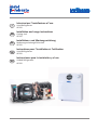 1
1
-
 2
2
-
 3
3
-
 4
4
-
 5
5
-
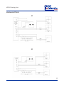 6
6
-
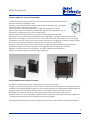 7
7
-
 8
8
-
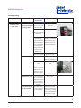 9
9
-
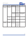 10
10
-
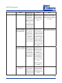 11
11
-
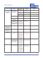 12
12
-
 13
13
-
 14
14
-
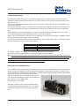 15
15
-
 16
16
-
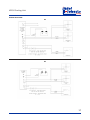 17
17
-
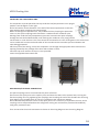 18
18
-
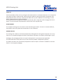 19
19
-
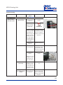 20
20
-
 21
21
-
 22
22
-
 23
23
-
 24
24
-
 25
25
-
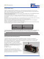 26
26
-
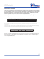 27
27
-
 28
28
-
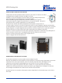 29
29
-
 30
30
-
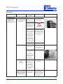 31
31
-
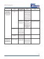 32
32
-
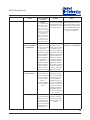 33
33
-
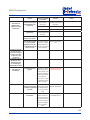 34
34
-
 35
35
-
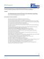 36
36
-
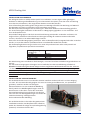 37
37
-
 38
38
-
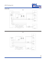 39
39
-
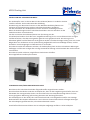 40
40
-
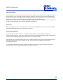 41
41
-
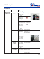 42
42
-
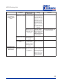 43
43
-
 44
44
-
 45
45
-
 46
46
-
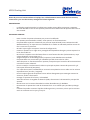 47
47
-
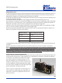 48
48
-
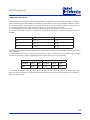 49
49
-
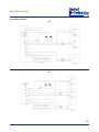 50
50
-
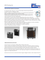 51
51
-
 52
52
-
 53
53
-
 54
54
-
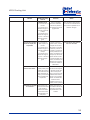 55
55
-
 56
56
-
 57
57
-
 58
58
-
 59
59
-
 60
60


Indel Webasto Marine Isotherm VE150 Installation And Usage Instructions
- Tipo
- Installation And Usage Instructions
en otros idiomas
- français: Indel Webasto Marine Isotherm VE150
- italiano: Indel Webasto Marine Isotherm VE150
- English: Indel Webasto Marine Isotherm VE150
- Deutsch: Indel Webasto Marine Isotherm VE150
Artículos relacionados

Otros documentos
-
 Indel Webasto BI53F Installation And Usage Instructions
-
Liebert Hisp Manual de usuario
-
ATEN VE550 Guía de inicio rápido
-
Sony WS-F150 El manual del propietario
-
-
-
Webasto DBW 2010 Instrucciones de operación
-
-
-
Carrier 40SMC036N Guía del usuario
