GE JVW5301SJSS Guía de instalación
- Categoría
- Campanas de cocina
- Tipo
- Guía de instalación
Este manual también es adecuado para
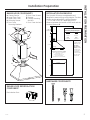
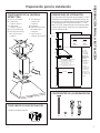
El GE Profile JVW5301SJSS es una campana extractora de pirámide que se puede instalar para ventilación externa o recirculación, lo que le brinda flexibilidad en su configuración de cocina. Con su potente motor y diseño elegante, esta campana extractora está diseñada para eliminar eficazmente el humo, los olores y la grasa del aire, manteniendo su cocina limpia y fresca.
El GE Profile JVW5301SJSS es una campana extractora de pirámide que se puede instalar para ventilación externa o recirculación, lo que le brinda flexibilidad en su configuración de cocina. Con su potente motor y diseño elegante, esta campana extractora está diseñada para eliminar eficazmente el humo, los olores y la grasa del aire, manteniendo su cocina limpia y fresca.


-
 1
1
-
 2
2
-
 3
3
-
 4
4
-
 5
5
-
 6
6
-
 7
7
-
 8
8
-
 9
9
-
 10
10
-
 11
11
-
 12
12
-
 13
13
-
 14
14
-
 15
15
-
 16
16


GE JVW5301SJSS Guía de instalación
- Categoría
- Campanas de cocina
- Tipo
- Guía de instalación
- Este manual también es adecuado para
El GE Profile JVW5301SJSS es una campana extractora de pirámide que se puede instalar para ventilación externa o recirculación, lo que le brinda flexibilidad en su configuración de cocina. Con su potente motor y diseño elegante, esta campana extractora está diseñada para eliminar eficazmente el humo, los olores y la grasa del aire, manteniendo su cocina limpia y fresca.
en otros idiomas
- English: GE JVW5301SJSS Installation guide
Artículos relacionados
-
GE JVW5301EJES Guía de instalación
-
GE PVW7301EJES Guía de instalación
-
GE Appliances UVW8301SLSS Manual de usuario
-
GE 1143742 Guía del usuario
-
-
 GE Appliances UVW9301BLTS Guía de instalación
-
-
GE Appliances JVW5301SJSS El manual del propietario
