GE JVW5301SJSS Guía de instalación
- Categoría
- Campanas de cocina
- Tipo
- Guía de instalación

Installation
Instructions
If you have questions, call GE Appliances at 800.GE.CARES (800.432.2737)
or visit our website at: GEAppliances.com
INSTALLATION INSTRUCTIONS
BEFORE YOU BEGIN
Read these instructions completely and
carefully.
•
IMPORTANT ³Save these instructions
for local inspector’s use.
•
IMPORTANT ³ Observe all governing
codes and ordinances.
•
Note to Installer – Be sure to leave these
instructions with the Consumer.
• Note to Consumer – Keep these instructions
for future reference.
• Skill level – Installation of this vent hood
requires basic mechanical and electrical skills.
• Completion time – Approximately
1 to 3 hours
• Proper installation is the responsibility of the
installer.
• Product failure due to improper installation is
not covered under the Warranty.
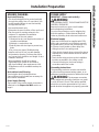
FOR YOUR SAFETY:
WARNING: Before beginning the
installation, switch power off at service panel and
lock the service disconnecting means to prevent
power from being switched on accidentally.
When the service disconnecting means cannot
be locked, securely fasten a prominent warning
device, such as a tag, to the service panel.
CAUTION: Due to the weight and size of
these vent hoods and to reduce the risk of
personal injury or damage to the product, TWO
PEOPLE ARE REQUIRED FOR PROPER
INSTALLATION.
Pyramid Wall
Chimney Vent Hoods
JVW5301, JVW5361
WARNING: TO REDUCE THE RISK OF
FIRE, ELECTRIC SHOCK OR INJURY TO PERSONS,
OBSERVE THE FOLLOWING:
A. Installation work and electrical wiring must be
done by qualified person(s) in accordance with
all applicable codes and standards, including
fire-rated construction.
B. Sufficient air is needed for proper combustion
and exhausting of gases through the flue
(chimney) of fuel burning equipment to
prevent back drafting. Follow the heating
equipment manufacturer’s guidelines and
safety standards such as those published by
the National Fire Protection Association (NFPA),
the American Society for Heating, Refrigeration
and Air Conditioning Engineers (ASHRAE) and
the local code authorities.
C. When cutting or drilling into wall or ceiling, do
not damage electrical wiring and other hidden
utilities.
D. Ducted fans must always be vented to the
outdoors.
E. Turn off breaker to adjacent rooms while
working.
WARNING: TO REDUCE THE RISK OF
FIRE, USE ONLY METAL DUCT WORK.
(991.0480.581) 31-10983-4 08-16 GE

2
31-10983-4
INSTALLATION PREPARATION
Installation Preparation
INSTALLATION CLEARANCES
These vent hoods are designed to be installed
onto a wall with no above cabinets.
The vent hood must be installed 24” minimum
above the cooking surface. For optimal
performance and usability, installing the hood
more than 38" above the cooking surface is
not recommended. The hood installation height
above the cooking surface depends upon ceiling
height and duct cover limitations. The telescopic
duct cover conceals the ductwork running from
the top of the hood to the ceiling. For supplied
duct cover ceiling heights, see table on page 5.
NOTE: Installation height should be measured
from the cooking surface to the lowest part
of the hood. This hood must be installed onto
a wall. It can be vented to the outdoors, or it
can be installed for recirculating operation. For
recirculation operation, see Recirculation Install
Planning.
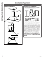
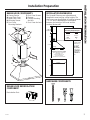
PRODUCT DIMENSIONS
8-1/4”
13”
30” to 36”
1-3/8”
9-7/8”
17-3/8” Min.
24-7/16" Max.
18-1/2”
3-5/16”
7-1/16”
13”
5”
2”
4-1/4”
24” Required Min.
38” Recommended Max.

31-10983-4
3
INSTALLATION PREPARATION
Installation Preparation
POWER SUPPLY
IMPORTANT – (Please read carefully)
WARNING:
FOR PERSONAL SAFETY, THIS APPLIANCE MUST BE
PROPERLY GROUNDED.
Remove house fuse or open circuit breaker
before beginning installation.
Do not use an extension cord or adapter plug
with this appliance. Follow National Electrical
Codes or prevailing local codes and ordinances.
Electrical supply
These vent hoods must be supplied with 120V,
60Hz, and connected to an individual, properly
grounded branch circuit, and protected by a 15
or 20 amp circuit breaker or time delay fuse.
• Wiring must be 2 wire with ground.
• If the electrical supply does not meet the above
requirements, call a licensed electrician before
proceeding.
• Route house wiring as close to the installation
location as possible in the ceiling or wall.
• Connect the wiring to the house wiring in
accordance with local codes.
Grounding instructions
The grounding conductor must be connected to
a ground metal, permanent wiring system, or an
equipment-grounding terminal or lead on the hood.
WARNING:
The improper connection
of the equipment-grounding conductor can result
in a risk of electric shock. Check with a qualified
electrician or service representative if you are in
doubt whether the appliance is properly grounded.
ADVANCE PLANNING
Duct Install Planning
• This hood is designed to be vented vertically
through the ceiling. Use a 6" round duct. Use
locally supplied elbows to vent horizontally
through the rear wall.
• Use metal ductwork only.
• Determine the exact location of the vent hood.
• Plan the route for venting exhaust to the
outdoors. To maximize the ventilation
performance of the vent system:
1. Minimize the duct run length and number of
transitions and elbows.
2. Maintain a constant duct size.
3. Seal all joints with duct tape to prevent any
leaks.
4. Do not use any type of flexible ducting.
• Install a wall cap or roof cap with damper
at the exterior opening. Purchase the wall or
roof cap and any transition and length of duct
needed in advance.
• When applicable, install any makeup
(replacement) air system in accordance
with local building code requirements. Visit
GEAppliances.com for available makeup air
solutions.
Recirculation Install Planning
A recirculation duct (included) and two
charcoal filters (not included) are necessary for
recirculation installation.
Power Supply Planning
The location of the power supply connection is
called out in the Prepare the Wall section on
page 6.

4
31-10983-4
REMOVE THE PACKAGING
CAUTION: Wear gloves to protect
against sharp edges.
• Remove the duct covers.
• Remove the hardware bag, literature package
and other boxed parts.
• Remove and properly discard the protective
plastic wrapping and other packaging materials.
TOOLS AND MATERIALS REQUIRED
(NOT SUPPLIED)
Wire cutter/stripper
Spirit level
Aluminized
Duct tape
Safety glasses
Strain relief for
junction box
Electric drill, #2 Phillips,
flat head, and 9/32" drill bit
UL listed wire nuts
Pencil and tape measure
PLAN THE INSTALLATION
CAUTION: To reduce risk of fire and to
properly exhaust air, be sure to duct the air
outside – Do not vent exhaust air into spaces
within walls or ceilings or into attics, crawl spaces,
or garages.
PARTS SUPPLIED FOR INSTALLATION
• 1 Hardware Package
• 1 Literature Package
PARTS NEEDED FOR INSTALLATION
• 1 Strain Relief
• Power Supply Cable
• 1 Wall or Roof Cap (for external venting only)
• All Metal Ductwork (for external venting only)
• Recirculation Duct (for recirculation install only)
WARNING:
PERSONAL INJURY HAZARD
Because of the weight and size of the range hood
canopy. It is recommended that 2 people are used
to install the range hood. Failure to properly lift
range hood could result in damage to the product
or personal injury.
NOTE: This range hood can be installed as either
ducted or recirculation. In a ducted application,
this range hood can be vented through the wall or
ceiling. When installed for recirculation, the range
hood vents out the sides of the duct cover.
NOTE: Before making any cuts or holes for
installation, determine which venting method will
be used and carefully calculate all measurements.
INSTALLATION PREPARATION
Installation Preparation

31-10983-4
5
INSTALLATION PREPARATION
Installation Preparation
INSTALLATION DIMENSIONS
The Pyramid Chimneys are adjustable and
designed to meet varying ceiling heights. The
duct covers can be adjusted for ceilings between
7’ 3 1/4” and 9’ depending on the distance
between the bottom of the hood and the
cooktop (distance X).
RANGE HOOD COMPONENTS
A. Canopy Section
B. Lower Duct Cover
C. Upper Duct Cover
D. Mounting Screws
E. Duct Cover
Mounting Brackets
F. Duct Cover Screws
G. Damper
H. Canopy Mounting
Anchors
I. Duct Cover Anchors
RANGE HOOD RECIRCULATION
COMPONENT
Recirculation Duct
Required Min & Recommended
Max Ceiling Height Examples
x = 24" x = 38"
Min Min
7' 3-1/4" 8' 5-1/4"
Max Max
7' 10-5/16" 9’
4-3/8 ”min
11-7/16” max
13”
9-7/8”
36”
X
18-1/2”
X = Distance From Hood To Cooktop
(Varies depending on installation)
Required Min - 24”,
Recommended Max - 38”
also consult cooktop
manufacturer’s recommendation
For higher ceiling
installations up
to 10’, use the
High Ceiling
Duct Cover Kit
for your model.
Use JXDC72SS for
Stainless Steel,
or JXDC72ES for
Slate.
Upper Duct Cover
Lower Duct Cover
Canopy
19-3/4”
A
D
B
F
F
D
D
D
E
C
G
I
I
I
H
HARDWARE COMPONENTS
DF H I

6
31-10983-4
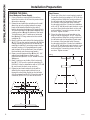
PREPARE THE WALL
Hood Body and Power Supply
1. Put a protective covering over the surface
below the location of the hood to protect from
dirt and/or damage.
2. Determine and mark the centerline on the wall
(draw line up to the ceiling) where the range
hood will be installed. Based on the ceiling
height, determine the distance 24” required min,
38” recommended max (X) needed between the
cooking surface (B) and the bottom of the hood.
To this distance, add 7” and draw a horizontal
line (A) about 24” long centered on the vertical
centerline (C).
3. Mark 2 points on each side of the horizontal line
(A), 5-1/2" from the vertical centerline (C). Drill the
canopy mounting anchors into the wall at the
markings. Install the 2 mounting screws into the
anchors, leaving a 1/4" gap between the wall
and the back of the screw head. (You will place
the hood body onto these screw heads.)
4. Draw a second horizontal line (D) that is 1-1/4"
added from the X distance. Draw a third
horizontal line (E) that is 4-5/16" added from the
X distance.
5. Mark 2 points on each side of the horizontal
line (D), 7-7/8" from the vertical centerline (C).
Drill the 2 holes for installation with a 9/32" drill
bit, and insert the duct cover anchors.
6. Determine and mark where the hole will be
drilled for the power supply cable to be run
through the wall. Mark a point on the left side
of the horizontal line (E), 6-1/4" from the vertical
centerline (C). Drill a 1-1/4" hole at this mark.
Installation Preparation
INSTALLATION PREPARATION
Duct Covers
1. Place one of the duct cover brackets against
the wall so that its top edge is 1/16” from the
ceiling and level. Align the center notches of
the bracket and the centerline (C) and mark
the centers of the bracket holes. Remove
the bracket to drill the 2 holes for installation
with a 9/32" drill bit, and insert the duct cover
anchors. Place the bracket back on the wall
and install the 2 mounting screws into the
anchors. Tighten screws.
2. Place the other duct cover bracket on the
wall so that its top edge is 10-1/2” from the
ceiling and level. Align the center notches of
the bracket and the centerline (C) and mark
the centers of the bracket holes. Remove
the bracket to drill the 2 holes for installation
with a 9/32" drill bit, and insert the duct cover
anchors. Place the bracket back on the wall
and install the 2 mounting screws into the
anchors. Tighten screws.
1-1/4"
4-5/16"
6-1/4"
7"
X
5-1/2" 5-1/2"
A
E
D
C
B
7-7/8" 7-7/8"
C
1/16"
Ceiling
10-1/2"

31-10983-4
7
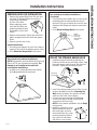
Installation Instructions
Non-vented (recirculation) Installations
NOTE: Recirculation duct (included) and charcoal
filters JXCF72 (not included) are required. The
damper is not installed on the unit with
recirculation installations.
1. Install the non-vented (ductless) recirculation
duct (A) supplied with the vent hood.
Non-vented (recirculation) Installations
(Continued)
2. Check that the recirculation duct is in the correct
orientation with the hole towards the front of
the hood. Fit the recirculation duct over the vent
exhaust outlet (B) and push down to seat on the
outlet.
3. Go to Mount the Range Hood in this section.
PREPARE HOOD FOR INSTALLATION
1. Remove the grease filters from the unit and
set aside. The grease filters are removed
by pressing the handle
in front of the filter.
When replacing, make
sure that the filters are
properly positioned with
the handles in front and
visible.
2. Remove and properly discard the protective
plastic wrapping from the hood and grease
filters.
3. Remove junction box cover.
Vented Installations
1. Securely press damper on top of the exhaust
opening. Check that the damper opens freely.
2. Go to Mount the Range Hood in this section.
B
A
INSTALLATION INSTRUCTIONS
NOTE:
Hole must
be facing
toward front
of hood.
MOUNT THE PYRAMID RANGE HOOD
1. Install the range hood body by placing the
hood key holes over the mounting screws. Feed
the power supply cable through the electrical
knockout. Tighten the mounting screws.
2. Insert 2 mounting screws into the 2 duct cover
anchors (installed on line D in Preparing the
Wall section) located in the slots on the back
surface of the hood. Secure tightly.
3. Connect the house ducting to the damper
on the hood body if ducted install. Seal all
connections with duct tape.
NOTE: If recirculation installation, skip to Step 4
and proceed.
4. Install the upper duct cover.
Slightly spread the sides of
the cover apart and hook
them behind the duct cover
mounting brackets. Attach
the cover to the brackets
with 4 duct cover screws.
A
Mounting
Screw Slots

8
31-10983-4
FINISH THE INSTALLATION
1. For recirculation installation only: Attach the
CHARCOAL FILTERS (not included) to both sides
of the blower. To do this, place the side of the
charcoal filter with the tabs against the side
of the blower. Align the double lines on the
charcoal filter with the "unlocked" symbol on
the blower. Push and twist downward until the
double lines align with the "locked" symbol on
the blower. Repeat on other side with second
filter.
For recirculation and ducted installation:
2. Replace the grease filters.
FINISH THE INSTALLATION
(Continued)
3. Using a flathead screwdriver, lift up the tabs on
the top of the canopy.
4. To install the lower duct cover:
• Use a flat head screwdriver to push the
two tabs forward on the lower duct cover.
• Angle the duct cover to slide the tabs
under the ledge of the hood body. Seat the
back of the duct cover on the top of the
range hood between the edges and tabs.
5. Turn the power supply on. Turn on blower
and light. If the range hood does not operate,
check that the circuit breaker is not tripped
or the house fuse blown. If the unit still does
not operate, disconnect the power supply and
check that the wiring connections have been
made properly.
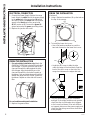
ELECTRICAL CONNECTION
1. Connect the Power Supply Cable to the range
hood. Attach the white lead of the power supply
to the white lead of the range hood (A) with a
wire nut (C). Attach the black lead of the power
supply to the black lead of the range hood
(B) with a wire nut (C). Connect the green (D)
ground wire under the green grounding screw.
2. Replace the junction box cover.
Installation Instructions
INSTALLATION INSTRUCTIONS
Tabs
B
D
C
A

Instrucciones
de instalación
Ante cualquier duda, llame a GE Appliances al 800.GE.CARES (800.432.2737)
o visite nuestro sitio Web en: GEAppliances.com
INSTRUCCIONES DE INSTALACIÓN
ANTES DE COMENZAR
Lea estas instrucciones por completo y con
detenimiento.
•
IMPORTANTE ³*XDUGHHVWDV
instrucciones para el uso de inspectores
locales.
•
IMPORTANTE ³&XPSODFRQWRGRVORV
códigos y ordenanzas vigentes.
•
Nota al instalador – Asegúrese de dejar estas
LQVWUXFFLRQHVFRQHO&RQVXPLGRU
• Nota al consumidor –&RQVHUYHHVWDV
instrucciones para referencia futura.
• Nivel de capacidad – La instalación de esta
campana de ventilación requiere capacidades
mecánicas y eléctricas básicas.
• Tiempo de finalización – Aproximadamente
de 1 a 3 horas.
• El instalador tiene la responsabilidad de
efectuar una instalación adecuada.
/D*DUDQWtDQRFXEUHODVIDOODVGHOSURGXFWR
debido a una instalación incorrecta.
PARA SU SEGURIDAD:
ADVERTENCIA: Antes de comenzar
ODLQVWDODFLyQGHVFRQHFWHODHQHUJtDGHOSDQHOGH
servicio y bloquee los medios de desconexión
SDUDHYLWDUHODFFLRQDPLHQWRGHODHQHUJtDGH
PDQHUDDFFLGHQWDO&XDQGRORVPHGLRVGH
desconexión de servicio no pueden bloquearse,
coloque sobre el panel de servicio un dispositivo
de advertencia bien visible, como una etiqueta.
PRECAUCIÓN: Debido al peso
y tamaño de estas campanas de ventilación y
para reducir el riesgo de lesiones personales o
daños al producto, SE NECESITAN DOS
PERSONAS PARA REALIZAR UNA INSTALACIÓN
CORRECTA.
Campanas de Ventilación de Chimeneas
de Pared Pirámide
JVW5301, JVW5361
ADVERTENCIA: PARA REDUCIR EL
RIESGO DE INCENDIO, DESCARGA ELÉCTRICA
O LESIONES A PERSONAS, CUMPLA CON LOS
SIGUIENTES PUNTOS:
A. El trabajo de instalación y el cableado
eléctrico deben ser realizados por una
persona(s) calificada de acuerdo con todos los
códigos y estándares aplicables, incluyendo
construcciones resistentes al fuego.
B. Es necesario contar con suficiente cantidad de
aire para una combustión y salida de gases
adecuadas a través del conducto (chimenea)
del equipo de consumo de combustible, a
fin de evitar ráfagas de aire. Siga las pautas
del fabricante del equipo de calefacción y
los estándares de seguridad, tales como
aquellos publicados por la Asociación
Nacional de Protección contra Incendios
(National Fire Protection Association, NFPA), la
6RFLHGDG(VWDGRXQLGHQVHSDUDOD&DOHIDFFLyQ
(American Society for Heating), los Ingenieros
de Refrigeración y Acondicionadores de Aire
5HIULJHUDWLRQDQG$LU&RQGLWLRQLQJ(QJLQHHUV
ASHRAE) y las autoridades de los códigos locales.
&$OFRUWDURSHUIRUDUXQDSDUHGRXQFLHORUUDVR
no dañe el cableado eléctrico y de otros
servicios ocultos.
D. Los ventiladores con conducto siempre deben
contar con ventilación hacia el exterior.
E. Desconecte el disyuntor de habitaciones
adyacentes mientras esté trabajando.
ADVERTENCIA: A FIN DE REDUCIR
EL RIESGO DE INCENDIOS, USE SÓLO
CONDUCTOS DE METAL.
*(

2
31-10983-4
PREPARACIÓN PARA LA INSTALACIÓN
Preparación para la instalación
ESPACIO DE INSTALACIÓN
Estas campanas de ventilación están diseñadas
para ser instaladas en una pared sin gabinetes
superiores.
La campana de ventilación debe ser instalada a un
PtQLPRGHµVREUHODVXSHUILFLHGHFRFFLyQ3DUD
un rendimiento y uso óptimos, no se recomienda
ODLQVWDODFLyQGHODFDPSDQDDPiVGHµVREUHOD
superficie de cocción. La altura de instalación de la
campana sobre la superficie de cocción depende
de la altura del cielorraso y las limitaciones de la
cubierta del conducto. La cubierta plegable oculta
los conductos que van desde la parte superior de
la campana hasta el cielorraso. Para las alturas de
cielorraso de las cubiertas de conductos, consulte
la tabla de la página 5.
NOTA: La altura de instalación debe medirse
desde la superficie de cocción hasta la parte
más baja de la campana. Esta campana debe
ser instalada sobre una pared. Puede contar
con ventilación hacia el exterior, o puede
ser instalada para un funcionamiento con
recirculación. Para un funcionamiento con
recirculación, consulte la Planificación para la
Instalación con Recirculación.
DIMENSIONES DEL PRODUCTO
µ
µ
µWRµ
µ
µ
µ0LQ
0D[
µ
µ
µ
µ
µ
µ
µ
µ0tQ5HTXHULGR
µ0i[5HTXHULGR

31-10983-4
3
INSTALLATION PREPARATION
Preparación para la instalación
PLANIFICACIÓN PREVIA
Planificación para la Instalación con Conducto
• Esta campana está diseñada para ventilarse
en forma vertical a través del cielorraso.
8VHXQFRQGXFWRFLUFXODUGHµUtilice codos
suministrados en forma local para ventilación
horizontal a través de la pared trasera.
• Determine la ubicación exacta de la campana
de ventilación.
• Planifique el recorrido de la salida de ventilación
hacia el exterior. A fin de maximizar el
rendimiento de la ventilación del sistema de
ventilación:
0LQLPLFHODORQJLWXGGHOFRQGXFWR\HOQ~PHUR
de transiciones y codos.
0DQWHQJDXQWDPDxRGHFRQGXFWRFRQVWDQWH
3. Selle todas las juntas con cinta para
conductos a fin de evitar pérdidas.
4. No utilice conductos flexibles de ningún tipo.
• Instale una cubierta de pared o casquete
de techo con un regulador de tiro en la
abertura exterior. Solicite por adelantado la
cubierta de pared o el casquete de techo y
cualquier transición o longitud de conducto
necesarios.
&XDQGRFRUUHVSRQGDLQVWDOHXQVLVWHPDGH
reposición (reemplazo) de aire de acuerdo con
los requisitos del código local de construcción.
Para acceder a soluciones de aire disponibles,
YLVLWH*($SSOLDQFHVFRP
Planificación de Instalación con Recirculación
Un conducto de recirculación (incluido) y un filtro
de carbón (no incluido) son necesarios para la
instalación con recirculación.
Planificación del Suministro de Corriente
La ubicación de la conexión del suministro
de corriente es indicada en la sección de
Preparación de la Pared en la página 6.
SUMINISTRO DE ENERGÍA
IMPORTANTE – (Tenga a bien leer cuidadosamente)
ADVERTENCIA:
3$5$6(*85,'$'3(5621$/(67($3$5$72
'(%(&21(&7$56($7,(55$'(0$1(5$
$'(&8$'$
Quite el fusible o abra el interruptor de circuitos
antes de comenzar la instalación.
No utilice un cable de extensión o un enchufe
DGDSWDGRUFRQHVWHDUWHIDFWR6LJDORV&yGLJRV
Eléctricos Nacionales o códigos y ordenanzas
locales vigentes.
Suministro eléctrico
Estas campanas de ventilación deben contar
con un suministro de 120V, 60Hz, deben estar
conectadas a un circuito derivado individual con
una adecuada conexión a tierra y deben contar
con la protección de un interruptor de circuitos
o un fusible con retraso de 15 o 20 amperios.
• El cableado debe ser de 2 hilos con conexión
a tierra.
• Si el suministro eléctrico no cumple con los
requisitos anteriores, llame a un electricista con
licencia antes de continuar.
• Dirija el cableado doméstico lo más cerca
posible a la ubicación de la instalación, en el
cielorraso o pared trasera. Ver página 14 para
más detalles.
&RQHFWHHOFDEOHDGRDOFDEOHDGRGRPpVWLFR
en cumplimiento con los códigos locales.
Instrucciones de conexión a tierra
El conductor a tierra debe conectarse a un metal
con conexión a tierra, un sistema de cableado
permanente o una terminal o conductor de
conexión a tierra del equipamiento en la
campana.
ADVERTENCIA: Una conexión
inadecuada del conductor de conexión a tierra
del equipamiento puede provocar un riesgo
GHGHVFDUJDHOpFWULFD&RQVXOWHDXQHOHFWULFLVWD
calificado o representante de servicio técnico
si tiene dudas sobre la correcta conexión a tierra
del artefacto.

4
31-10983-4
HERRAMIENTAS Y MATERIALES
REQUERIDOS
(NO SUMINISTRADOS)
Alicate pelacables
Nivel
&LQWDDLVODQWH
de aluminio
*DIDVGHVHJXULGDG
Alivio de tensión para
la caja de conexiones
Broca eléctrica con Phillips
Nº 2 de cabeza plana y
EURFDGHµ
7DSRQHVGH
alambre aprobados
por UL
Lápiz y cinta métrica
PREPARACIÓN PARA LA INSTALACIÓN
Preparación para la instalación
QUITE EL ENVOLTORIO
PRECAUCIÓN: Se guantes para
protegerse de los bordes afilados.
• Quite las cubiertas de los conductos.
• Quite la bolsa de piezas, el paquete
de instrucciones y otras piezas en cajas.
• Quite y descarte adecuadamente el envoltorio
plástico de protección y otros materiales
de empaque.
PLAN DE INSTALACIÓN
PRECAUCIÓN: A fin de reducir
riesgos de incendios y para que el aire salga de
forma apropiada, asegúrese de que el aire sea
conducido hacia fuera - No ventile el aire de la
salida hacia espacios dentro de paredes o
cielorrasos o áticos, espacios muy bajos o garajes.
PIEZAS PROVISTAS PARA LA
INSTALACIÓN
• 1 Paquete de Herramientas
• 1 Paquete Escrito
PIEZAS NECESARIAS PARA LA
INSTALACIÓN
• 1 Amortiguador de Refuerzo
• &DEOHGH6XPLQLVWURGH&RUULHQWH
•8QD7DSDGH3DUHGR7HFKRSDUDYHQWLODFLyQ
con conducto únicamente)
•7RGDOD7XEHUtD0HWiOLFDSDUDYHQWLODFLyQFRQ
conducto únicamente)
•&RQGXFWRGH5HFLUFXODFLyQSDUDLQVWDODFLyQFRQ
recirculación únicamente)
ADVERTENCIA:
! RIESGO DE LESIONES PERSONALES
Debido al peso y tamaño de la base de la
campana extractora. Es recomendable que
la campana extractora sea instalada por 2
personas. Si la campana no es elevada de forma
correcta, se podrán producir daños sobre el
producto o lesiones personales.
NOTA: Esta campana puede ser instalada con
conducto o con recirculación. En una aplicación
con conducto, esta campana puede ser ventilada a
través de la pared o del cielorraso. Al ser instalada
por recirculación, la campana ventila hacia afuera
los costados de la cubierta del conducto.
NOTA: Antes de realizar cualquier corte o agujero
para la instalación, determine qué método de
ventilación será usado y con cuidado calcule
todas las medidas.

31-10983-4
5
PREPARACIÓN PARA LA INSTALACIÓN
Preparación para la instalación
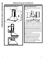
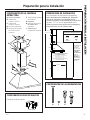
DIMENSIONES DE INSTALACIÓN
/DV&KLPHQHDVGH3LUiPLGHVRQDMXVWDEOHV\
están diseñadas para adaptarse a diferentes
alturas de cielorraso. Las cubiertas de los
conductos pueden ser ajustadas para cielorrasos
GHHQWUH·µDQG·GHSHQGLHQGRGHOD
distancia entre la parte inferior de la campana y
la superficie de cocción (distancia X).
COMPONENTES DE LA CAMPANA
EXTRACTORA
A. Sección de la Base
B. &XELHUWDGHO
&RQGXFWR,QIHULRU
C. &XELHUWDGHO
&RQGXFWR6XSHULRU
D. 7RUQLOORVGH0RQWDMH
E. 6RSRUWHVGH0RQWDMH
GHOD&XELHUWDGHO
&RQGXFWR
F. 7RUQLOORVGHOD&XELHUWD
GHO&RQGXFWR
G. Regulador
H. 6RSRUWHVGH0RQWDMH
de la Base de la
&DPSDQD
I. Soportes de la
&XELHUWDGHO&RQGXFWR
COMPONENTES DE RECIRCULACIÓN
&RQGXFWRGH5HFLUFXODFLyQ
µ
µ
µ
X
µ
Para instalaciones
en cielo rasos
más altos de
hasta 10’, use el
Kit del Cobertor
de Tuberías
para Cielo Rasos
acorde a su
modelo. Use el
JXDC72SS para
Acero Inoxidable,
o el JXDC72ES
para Losa.
&XELHUWDGHO&RQGXFWR6XSHULRU
&XELHUWDGHO&RQGXFWR,QIHULRU
Dosel
µ
A
D
B
F
F
D
D
D
E
C
G
I
I
I
H
COMPONENTES DE LAS HERRAMIENTAS
DF H I
X = Distancia Desde la Campana Hasta
la Superficie de Cocción
9DUtDGHSHQGLHQGRGHODLQVWDODFLyQ
0tQLPR5HTXHULGR²µ
0i[LPR5HTXHULGR²µ
también consulte la recomendación del
fabricante de cocinas
Ejemplos de Altura Mínima Requerida y
Altura Máxima Recomendada de Cielorraso
x = 24" x = 38"
Mín. Mín
7' 3-1/4" 8' 5-1/4"
Máx. Máx.
7' 10-5/16" 9’
0tQGHµ
0i[GHµ

6
31-10983-4
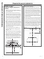
PREPARE LA PARED
Cuerpo de la Campana y Suministro de
Corriente
1.
&RORTXHXQDFXELHUWDSURWHFWRUDVREUHODVXSHUILFLH
debajo de la ubicación de la campana, a fin de proteger
de la suciedad y/o daños.
'HWHUPLQH\PDUTXHODOtQHDFHQWUDOVREUHODSDUHG
GLEXMHODOtQHDKDFLDDUULEDKDVWDHOFLHORUUDVRGRQGHOD
campana extractora será instalada. En base a la altura
GHOFLHORUUDVRGHWHUPLQHODGLVWDQFLDPtQLPDUHTXHULGD
GHµ\ODGLVWDQFLDPi[LPDUHFRPHQGDGDGHµX),
necesarias entre la superficie de cocción (B) y la parte
LQIHULRUGHODFDPSDQD$HVWDGLVWDQFLDDJUHJXHµ\
GLEXMHXQDOtQHDKRUL]RQWDO$GHDSUR[LPDGDPHQWHµ
GHORQJLWXGFHQWUDGDVREUHODOtQHDFHQWUDOYHUWLFDOC).
3. 0DUTXHSXQWRVDFDGDODGRGHODOtQHDKRUL]RQWDO
(ADòµGHVGHODOtQHDFHQWUDOYHUWLFDO$JXMHUHHORV
sostenes de montaje de la parte superior de la pared,
donde se encuentran las marcas. Instale los 2 tornillos
de montaje en los sostenes, dejando un espacio de
óµHQWUHODSDUHG\ODSDUWHWUDVHUDGHODFDEH]DGHO
tornillo. (Debe colocar el cuerpo de la campana en las
cabezas de estos tornillos).
0DUTXHXQDVHJXQGDOtQHDKRUL]RQWDODGHóµ
DJUHJDGDGHVGHODGLVWDQFLD;0DUTXHXQDWHUFHUD
OtQHDKRUL]RQWDODGHµDJUHJDGDGHVGHOD
distancia X.
5. 0DUTXHSXQWRVDFDGDODGRGHODOtQHDKRUL]RQWDO
(DDµGHVGHODOtQHDFHQWUDOYHUWLFDOC). Haga 2
DJXMHURVSDUDODLQVWDODFLyQFRQXQDEURFDGHµH
inserte los sostenes de la cubierta del conducto.
6. Determine y marque el lugar donde el agujero será
perforado para que el cable de suministro de corriente
SXHGDSDVDUDWUDYpVGHODSDUHG0DUTXHXQSXQWR
GHOODGRL]TXLHUGRGHODOtQHDKRUL]RQWDOEDòµ
GHVGHODOtQHDFHQWUDOYHUWLFDOC). Haga un agujero de
óµHQHVWDPDUFD
Preparación para la instalación
PREPARACIÓN PARA LA INSTALACIÓN
Cubiertas de Conductos
1. &RORTXHXQRGHORVVRSRUWHVGHODFXELHUWDGHO
conducto contra la pared, de modo que su extremo
VXSHULRUHVWpDµGHOFLHORUUDVR\TXHTXHGH
nivelado. Alinee las ranuras centrales del soporte
FRQODOtQHDFHQWUDOC) y marque los centros de los
agujeros del soporte. Retire el soporte para perforar
2 agujeros para la instalación con una broca de
µHLQVHUWHORVVRVWHQHVGHODFXELHUWDGHO
conducto. Vuelva a colocar el soporte en la pared
e instale los 2 tornillos de montaje en los sostenes.
Ajuste los tornillos.
&RORTXHHORWURVRSRUWHGHODFXELHUWDGHOFRQGXFWR
contra la pared, de modo que su extremo superior
HVWpDµGHOFLHORUUDVR\TXHTXHGHQLYHODGR
$OLQHHODVUDQXUDVFHQWUDOHVGHOVRSRUWHFRQODOtQHD
central (C) y marque los centros de los agujeros del
soporte. Retire el soporte para perforar 2 agujeros
SDUDODLQVWDODFLyQFRQXQDEURFDGHµHLQVHUWH
los sostenes de la cubierta del conducto. Vuelva a
colocar el soporte en la pared e instale los 2 tornillos
de montaje en los sostenes. Ajuste los tornillos.
1-1/4"
4-5/16"
6-1/4"
7"
X
5-1/2" 5-1/2"
A
E
D
C
B
7-7/8" 7-7/8"
C
1/16"
Ceiling
10-1/2"
&LHORUUDVR

31-10983-4
7
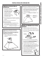
Instrucciones de instalación
Instalaciones sin ventilación (recirculación)
NOTA: Se requiere el conducto de recirculación
LQFOXLGR\ORVILOWURVGHFDUEyQ-;&)QRLQFOXLGRV
El regulador no está instalado en la unidad con
instalaciones de recirculación.
1. Instale el conducto de recirculación (A) (sin
conducto) suministrado con la campana de
ventilación.
Instalaciones sin ventilación (recirculación) (continúa)
&RQWUROHTXHHOFRQGXFWRGHUHFLUFXODFLyQVH
encuentre en la orientación correcta con el agujero
hacia el frente de la campana. Inserte el conducto
de recirculación sobre la salida del escape de
ventilación (B) y empuje hacia abajo para que
coincida con la salida.
&RQVXOWHVREUHHOMontaje de la Campana en esta
sección.
PREPARE LA CAMPANA PARA SU
INSTALACIÓN
1. Retire los filtros de grasa de la unidad y deje
los mismos a un lado. Los
filtros de grasa son retirados
presionando la manija que
se encuentra frente al filtro.
Al realizar el reemplazo,
asegúrese de que los
filtros estén correctamente
posicionados con las manijas
en el frente y visibles.
2. Retire y descarte de forma adecuada el envoltorio
protector de plástico de la campana y de los filtros
de grasa.
3. Retire la tapa de la caja de empalmes.
Instalaciones Ventiladas
1. De forma segura, presione el regulador que se
HQFXHQWUDVREUHODDEHUWXUDGHOHVFDSH&RQWUROH
que el regulador se pueda abrir libremente.
&RQVXOWHVREUHHOMontaje de la Campana en esta
sección.
B
A
INSTRUCCIONES DE INSTALACIÓN
127$(ODJXMHUR
debe estar
enfrentado hacia
el frente de la
campana.
MONTE LA CAMPANA DE LA COCINA
PIRÁMIDE
1. Instale el cuerpo de la campana de la cocina,
colocando los agujeros de la campana sobre los
WRUQLOORVGHOPRQWDMH&RQHFWHHOFDEOHGHVXPLQLVWUR
de corriente a través del tablero eléctrico. Ajuste los
tornillos de montaje.
2. Inserte 2 tornillos de montaje en los 2 sostenes
GHODFXELHUWDGHOFRQGXFWRLQVWDODGRVHQODOtQHD
D en la sección de Preparación de la Pared),
ubicados en las ranuras de la superficie trasera de
la campana. Ajuste de manera firme.
3. &RQHFWHHOFRQGXFWRKRJDUHxRDOUHJXODGRUGHO
cuerpo de la campana si se realizó una instalación
con un conducto. Selle todas las conexiones con cinta
para conducto. NOTA: Si se trata de una instalación
con recirculación, vaya al Paso 4 y proceda.
4. Instale la cubierta del conducto superior.
Lentamente separe los costados de la cubierta
y enganche ambos detrás de
los soportes de montaje de la
cubierta del conducto. Adhiera la
tapa a los soportes con 4 tornillos
de la cubierta del conducto.
A
Ranuras de
ORV7RUQLOORV
GH0RQWDMH

8
31-10983-4
FINALICE LA INSTALACIÓN
1. Sólo para instalaciones de recirculación: Adhiera
ORV),/7526'(&$5%Ï1QRLQFOXLGRVVREUHDPERV
lados del calefactor. Para hacer esto, coloque el
lateral del filtro de carbón con las lengüetas contra
HOFRVWDGRGHOFDOHIDFWRU$OLQHHODVOtQHDVGREOHV
GHOILOWURGHFDUEyQFRQHOVtPEROR´GHVEORTXHDGRµ
en el calefactor. Presione y doble hacia abajo hasta
TXHODVOtQHDVGREOHVVHDOLQHHQFRQHOVtPEROR
´EORTXHDGRµHQHOFDOHIDFWRU5HSLWDHVWHSURFHVR
del otro lado con el segundo filtro.
Para instalaciones de recirculación y con conducto:
2. Reemplace los filtros de grasa.
FINALICE LA INSTALACIÓN (continúa)
3. &RQXQGHVWRUQLOODGRUGHSXQWDSODQDOHYDQWHODV
lengüetas sobre el extremo de la parte superior.
4. Para instalar la cubierta del conducto inferior:
• Use un destornillador de cabeza plana para
empujar las dos lengüetas hacia delante sobre
la tapa del conducto inferior.
• Doble la cubierta del conducto para deslizar
las lengüetas debajo del estante del cuerpo
de la campana. Apoye la parte trasera de la
tapa del conducto sobre la parte superior de la
campana de la cocina, entre los extremos y las
lengüetas.
5. Encienda el suministro de corriente. Encienda el
calefactor y la luz. Si la campana de la cocina no
funciona, controle que el disyuntor no se haya
activado o que el fusible hogareño esté quemado. Si
la unidad aún no funciona, desconecte el suministro
de corriente y controle que las conexiones del
cableado hayan sido realizadas de forma correcta.
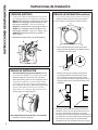
CONEXIÓN ELÉCTRICA
1. &RQHFWHHO&DEOHGH6XPLQLVWURGH&RUULHQWHD
ODFDPSDQDH[WUDFWRUD&RQHFWHHOFRQGXFWRU
blanco del suministro de corriente al conductor
blanco de la campana extractora (A) con una
tuerca para cable (C&RQHFWHHOFRQGXFWRU
negro del suministro de corriente al conductor
negro de la campana extractora (B) con una
tuerca para cable (C&RQHFWHHOFDEOHDWLHUUD
verde (D) debajo del tornillo de conexión a
tierra verde.
2. Reemplace la tapa de la caja de empalmes.
Instrucciones de instalación
INSTRUCCIONES DE INSTALACIÓN
7DEV
B
D
C
A
-
 1
1
-
 2
2
-
 3
3
-
 4
4
-
 5
5
-
 6
6
-
 7
7
-
 8
8
-
 9
9
-
 10
10
-
 11
11
-
 12
12
-
 13
13
-
 14
14
-
 15
15
-
 16
16


GE JVW5301SJSS Guía de instalación
- Categoría
- Campanas de cocina
- Tipo
- Guía de instalación
En otros idiomas
- English: GE JVW5301SJSS Installation guide
Documentos relacionados
-
GE Appliances JVW5301SJSS Guía de instalación
-
GE JVW5301EJES Guía de instalación
-
GE ZV30HSR2SS Guía de instalación
-
GE PV976N2SS El manual del propietario
-
GE Appliances UVW8301SLSS Manual de usuario
-
GE Appliances 1143742 Manual de usuario
-
-
GE Appliances JVW5301FJDS El manual del propietario
-
GE JVW5301 El manual del propietario
-
GE JVW5301SJSS El manual del propietario