Yamaha TG500 Manual de usuario
- Categoría
- Instrumentos musicales
- Tipo
- Manual de usuario


FCC INFORMATION (U.S.A.)
1. IMPORTANT NOTICE: DO NOT MODIFY THIS UNIT!
This product, when installed as indicated in the instructions contained in this manual, meets FCC requirements. Modifications not expressly approved
by Yamaha may void your authority, granted by the FCC, to use the product.
2. IMPORTANT: When connecting this product to accessories and/or another product use only high quality shielded cables. Cable/s supplied with this
product MUST be used. Follow all installation instructions. Failure to follow instructions could void your FCC authorization to use this product in the
USA.
3. NOTE: This product has been tested and found to comply with the requirements listed in FCC Regulations, Part 15 for Class ”B” digital devices.
Compliance with these requirements provides a reasonable level of assurance that your use of this product in a residential environment will not
result in harmful interference with other electronic devices. This equipment generates/uses radio frequencies and, if not installed and used according
to the instructions found in the users manual, may cause interference harmful to the operation of other electronic devices. Compliance with FCC
regulations does not guarantee that interference will not occur in all installations. If this product is found to be the source of interference, which can
be determined by turning the unit ”OFF” and ”ON”, please try to eliminate the problem by using one of the following measures:
Relocate either this product or the device that is being affected by the interference.
Utilize power outlets that are on different branch (circuit breaker or fuse) circuits or install AC line filter/s.
In the case of radio or TV interference, relocate/reorient the antenna. If the antenna lead-in is 300 ohm ribbon lead, change the lead-in to co-axial type
cable.
If these corrective measures do not produce satisfactory results, please contact the local retailer authorized to distribute this type of product. If you
can not locate the appropriate retailer, please contact Yamaha Corporation of America, Electronic Service Division, 6600 Orangethorpe Ave, Buena
Park, CA 90620
The above statements apply ONLY to those products distributed by Yamaha Corporation of America or its subsidiaries.
* This applies only to products distributed by YAMAHA CORPORATION OF AMERICA.
Dette apparat overholder det gaeldende EF-direktiv
vedrørende radiostøj.
Cet appareil est conforme aux prescriptions de la
directive communautaire 87/308/CEE.
Diese Geräte entsprechen der EG-Richtlinie 82/
499/EWG und/oder 87/308/EWG.
This product complies with the radio frequency
interference requirements of the Council Direc-
tive 82/499/EEC and/or 87/308/EEC.
Questo apparecchio è conforme al D.M.13 aprile
1989 (Direttiva CEE/87/308) sulla soppressione
dei radiodisturbi.
Este producto está de acuerdo con los requisitos
sobre interferencias de radio frequencia fijados
por el Consejo Directivo 87/308/CEE.
YAMAHA CORPORATION
Connecting the Plug and Cord
IMPORTANT. The wires in this mains lead are coloured in accordance with the following
code:
BLUE : NEUTRAL
BROWN : LIVE
As the colours of the wires in the mains lead of this apparatus may not correspond with the
coloured markings identifying the terminals in your plug proceed as follows:
The wire which is coloured BLUE must be connected to the terminal which is marked with
the letter N or coloured BLACK.
The wire which is coloured BROWN must be connected to the terminal which is marked
with the letter L or coloured RED.
Making sure that neither core is connected to the earth terminal of the three pin plug.
* This applies only to products distributed by YAMAHA - KEMBLE MUSIC (U.K.) LTD.
IMPORTANT NOTICE FOR THE UNITED KINGDOM
Litiumbatteri!
Bör endast bytas av servicepersonal.
Explosionsfara vid felaktig hantering.
VAROITUS!
Lithiumparisto, Räjähdysvaara.
Pariston saa vaihtaa ainoastaan alan
ammattimies.
ADVARSEL!
Lithiumbatteri!
Eksplosionsfare. Udskiftning må kun foretages
af en sagkyndig, – og som beskrevet i
servicemanualen.
CANADA
THIS DIGITAL APPARATUS DOES NOT EXCEED THE “CLASS B” LIMITS FOR RADIO
NOISE EMISSIONS FROM DIGITAL APPARATUS SET OUT IN THE RADIO INTERFER-
ENCE REGULATION OF THE CANADIAN DEPARTMENT OF COMMUNICATIONS.
LE PRESENT APPAREIL NUMERIQUE N’EMET PAS DE BRUITS RADIOELECTRIQUES
DEPASSANT LES LIMITES APPLICABLES AUX APPAREILS NUMERIQUES DE LA “CLASSE
B” PRESCRITES DANS LE REGLEMENT SUR LE BROUILLAGE RADIOELECTRIQUE
EDICTE PAR LE MINISTERE DES COMMUNICATIONS DU CANADA.
* This applies only to products distributed by YAMAHA CANADA MUSIC LTD.

SPECIAL MESSAGE SECTION
PRODUCT SAFETY MARKINGS: Yamaha electronic prod-
ucts may have either labels similar to the graphics shown
below or molded/stamped facsimiles of these graphics on the
enclosure. The explanation of these graphics appears on this
page. Please observe all cautions indicated on this page and
those indicated in the safety instruction section.
methods used to produce them, meet these goals. In keeping
with both the letter and the spirit of the law, we want you
to be aware of the following:
Battery Notice: This product MAY contain a small non-
rechargcable battery which (if applicable) is soldered in
place. The average life span of this type of battery is
approximately five years. When replacement becomes
neccessary, contact a qualified service representative to
perform the replacement.
Warning: Do not attempt to recharge, disassemble, or
incinerate this type of battery. Keep all batteries away from
children. Dispose of used batteries promptly and as regulated
by applicable laws. Note: In some areas, the servicer is
required by law to return the defective parts. However, you
do have the option of having the servicer dispose of these
parts for you.
Disposal Notice: Should this product become damaged
beyond repair, or for some reason its useful life is considered
to be at an end, please observe all local, state, and federal
regulations that relate to the disposal of products that contain
lead, batteries, plastics, etc.
NOTICE: Service charges incurred due to lack of knowl-
edge relating to how a function or effect works (when the
unit is operating as designed) are not covered by the manu-
facturer’s warranty, and are therefore the owners responsi-
bility. Please study this manual carefully and consult your
dealer before requesting service.
NAME PLATE LOCATION: The graphic below indicates
the location of the name plate. The model number, serial
number, power requirements, etc., are located on this plate.
You should record the model number, serial nunber, and the
date of purchase in the spaces provided below and retain this
manual as a permanent record of your purchase.
CAUTION: TO REDUCE THE RISK OF
ELECTRIC SHOCK, DO NOT REMOVE
COVER (OR BACK). NO USER-SERVICEABLE
PARTS INSIDE. REFER SERVICING TO
QUALIFIED SERVICE PERSONNEL
RISK OF ELECTRIC SHOCK
DO NOT OPEN
CAUTION
The exclamation point within the equilateral
triangle is intended to alert the user to the
presence of important operating and mainte-
nance (servicing) instructions in the litera-
ture accompanying the product.
The lightning flash with arrowhead symbol
within the equilateral triangle is intended to
alert the user to the presence of uninsulated
“dangerous voltage” within the product’s
enclosure that may be of sufficient magni-
tude to constitute a risk of electrical shock.
IMPORTANT NOTICE: All Yamaha electronic products are
tested and approvend by an independent safety testing labo-
ratory in order that you may be sure that when it is properly
installed and used in its normal and customary manner, all
foreseeable risks have been eliminated. DO NOT modify this
unit or commission others to do so unless specifically author-
ized by Yamaha. Product performance and/or safety standards
may be diminished. Claims filed under the expressed warranty
may be denied if the unit is/has been modified. Implied
warranties may also be affected.
SPECFICATIONS SUBJECT TO CHANGE: The informa-
tion contained in this manual is believed to be correct at the
time of printing. However, Yamaha reserves the right to
change or modify any of the specifications without notice or
obligation to update existing units.
ENVIRONMENTAL ISSUES: Yamaha strives to produce
products that are both user safe and environmentally friendly.
We sincerely believe that our products and the production
Model
Serial No.
Purchase Date
● Explanation of Graphical Symbols
This information on safety is provided to comply with U.S.A. laws, but should be observed by users in all countires.
92-4691

IMPORTANT SAFETY INSTRUCTIONS
INFORMATION RELATING TO PERSONAL INJURY, ELECTRICAL SHOCK,
AND FIER HAZARD POSSIBILITIES HAS BEEN INCLUDED IN THIS LIST.
PLEASE KEEP THIS MANUAL
8. This product was NOT designed for use in wet/damp
locations and should not be used near water or exposed to
rain. Examples of wet/damp locations are; near a swim-
ming pool, spa, tub, sink, or wet basement.
9. This product should be used only with the components
supplied or; a cart, rack, or stand that is recommended by
the manufacturer. If a cart, rack, or stand is used, please
observe all safety markings and instructions that accom-
pany the accessory product.
10.The power supply cord (plug) should be disconnected
from the outlet when electronic products are to be left
unused for extended periods of time. Cords should also be
disconnected when there is a high probability of lightening
and/or electrical storm activity.
11.Care should be taken that objects do not fall and liquids
are not spilled into the enclosure through any openings
that may exist.
12.Electrical/electronic products should be serviced by a
qualified service person when:
a. The power supply cord has been damaged; or
b. Objects have fallen, been inserted, or liquids have been
spilled into the enclosure through openings; or
c. The product has been exposed to rain; or
d. The product does not operate, exhibits a marked change
in performance; or
e. The product has been dropped, or the enclosure of the
product has been damaged.
13.Do not attempt to service this product beyond that de-
scribed in the user-maintenance instructions. All other
servicing should be referred to qualified service personnel.
14.This product, either alone or in combination with an
amplifier and headphones or speaker/s, may be capable of
producing sound levels that could cause permanent hear-
ing loss. DO NOT operate for a long period of time at a
high volume level or at a level that is uncomfortable. If
you experience any hearing loss or ringing in the cars, you
should cousult an audiologist. IMPORTANT: The louder
the sound, the shorter the time period before damage
occurs.
15.Some Yamaha products may have benches and/or acces-
sory mounting fixtures that are either supplied as a part of
the product or as optional accessories. Some of these items
are designed to be dealer assembled or installed. Please
make sure that benches are stable and any optional fixtures
(where applicable) are well secured BEFORE using. Benches
supplied by Yamaha are designed for seating only. No
other uses are recommended.
WARNING — When using any electrical or electronic prod-
uct, basic precautions should always be followed. These
precautions include, but are not limited to, the following:
1. Read all Safety Instructions, Installation Instructions, Spe-
cial Message Section items, and any Assembly Instruc-
tions found in this manual BEFORE making any connections,
including connection to the main supply.
2. Main Power Suplly Verifications: Yamaha products are
manufactured specifically for the supply voltage in the
area where they are to be sold. If you should move, or if
any doubt exists about the supply voltage in your area,
please contact your dealer for supply voltage verification
and (if applicable) instructions. The required supply volt-
age is printed on the name plate. For name plate location,
please refer to the graphic found in the Special Message
Section of this manual.
3. This product may be equipped with a polarized plug (one
blade wider than the other). If you are unable to insert the
plug into the outlet, turn the plug over and try again. If the
problem persists, contact electrician to have the obsolete
outlet replaced. Do NOT defeat the safety purpose of the
plug.
4. Some electronic products utilize external power supplies
or adapters. DO NOT connect this type of product to any
power supply or adapter other than one described in the
owners manual, on the name plate, or specifically recom-
mended by Yamaha.
5. WARNING: Do not place this product or any other objects
on the power cord or place it in a position where anyone
could walk on, trip over, or roll anything over power or
connecting cords of any kind. The use of an extension cord
is not recommended! If you must use an extension cord,
the minimume wire size for a 25' cord (or less) is 18 AWG.
NOTE: The smaller the AWG number, the larger the
current handling capacity. For longer extension cords,
consult a local electrician.
6. Ventilation: Electronic products, unless specifically de-
signed for enclosed installations, should be placed in
locations that do not interfere with proper ventilation. If
instructions for enclosed installations are not provided, it
must be assumed that unobstructed ventilation is required.
7. Temperature considerations: Electronic products should be
installed in locations that do not significantly contribute to
their operating temperature. Placement of this product
close to heat sources such as; radiators, heat registers and
other devices that produce heat should be avoided.
This information on safety is provided to comply with U.S.A. laws, but should be observed by users in all countires.
92-4692

i
The TG500 Tone Generator delivers the incredible Yamaha AWM2 sound
with improved quality and versatility. In addition to superior sound, the TG500
features “Quick Edit” modes that provide fast, easy access to the most impor-
tant voice and performance editing jobs so you can customize the sound with-
out having to deal with the details. Of course, you still have full programming
power when you want to do some serious voicing. In terms of sound and
programming power, the TG500 offers unprecedented levels of quality and
performance.
We urge you to read the owner’s manuals thoroughly in order to realize the
full potential of the TG500 (see “About the Manual” on page 5), and keep the
manuals in a safe place for future reference.
MAIN FEATURES
● AWM2 Sound, 64-note Polyphony
2nd-generation Advanced Wave Memory (AWM2) technology delivers
dazzling, true-to-life sound with 64-note polyphony.
● Large-capacity Waveform ROM
A huge 8-megabyte waveform ROM provides the kind of capacity required
for stunning, true-to-life sound.
● Expandable Waveform RAM
Up to 1-megabyte of waveform RAM can be installed to allow loading of
external samples via waveform cards or the MIDI Sample Dump protocol.
● 4-layer Performance Combinations
Voices can be played individually, or up to four voices can be combined
and “layered” to form performance combinations.
● 384 Presets and 192 User RAM Locations
The TG500 has 384 presets including 252 voices, 4 multi-instrument drum
voices, and 128 performance combinations. 192 internal RAM locations addi-
tionally store 126 voices, 2 drum voices, and 64 performance combinations.
The TG500 also provides RAM memory for 16 multi-play setups.
● Advanced Digital Filters
Programmable digital filters allow the TG500 sound to be tailored as re-
quired. The filters also feature a resonance parameter equivalent to that found
on the SY77 and SY99 Music Synthesizers.

ii
● Top-quality Effects
The basic quality of the TG500 voices is further enhanced by a range of
programmable effects offering quality rivalling some of the finest separate
signal processing systems.
● Other Features
• Slots for dual external memory card sets (VOICE and WAVE).
• Easy-to-read 24-character × 2-line backlit LCD display.
• Recognizes individual key aftertouch.
• Stereo L/R and 4 individual audio outputs.

iii
APPENDIX
UTILITY MODE / WAVE EDIT MODE
MULTI EDIT MODE
DRUM VOICE EDIT MODE
VOICE EDIT MODE
PERFORMANCE EDIT MODE
GETTING STARTED
FEATURE REFERENCE

iv
4. The Multi Mode ...................... 35
•WHAT’S IN A MULTI SETUP? .........35
•MULTI PLAY POLYPHONY &
DYNAMIC VOICE ALLOCATION ......36
•SELECTING A MULTI SETUP..........36
■ Editing a Multi Setup ...........................36
•THE MULTI PARAMETER EDIT
SCREENS ............................................37
•SELECTING DIFFERENT
INSTRUMENTS FOR EDITING.........38
•NO STORE OPERATION
REQUIRED ..........................................38
■ Further Possibilities… ..........................38
5. Voice Editing & Effects ............. 39
■ Bypassing the Effects While
Editing ....................................................41
■ Further Possibilities… ..........................41
Precautions .................................. 3
About the Manual .......................... 5
■ The Getting Started Section .................5
■ Icons.........................................................6
■ The Feature Reference Section ...........7
The Controls & Connectors.............. 8
■ Front Panel..............................................8
■ Rear Panel.............................................11
1. Setting Up Your System ............ 12
■ Connections...........................................12
■ Power-on Procedure.............................15
2. Selecting And Playing Voices..... 16
■ The Preset, Internal, & Card Voice
Memories ...............................................16
■ Select a Voice & Play..........................17
■ Internal Voice List.................................19
3. The Performance Mode............. 22
■ The Preset, Internal, & Card
Performance Memories ........................22
■ Play the Performance
Combinations.........................................24
■ Internal Performance List ....................25
■ Programming Your Own Performance
Combinations.........................................26
■ Further Possibilities… ..........................34
CONTENTS
Getting Started

v
General Editing Procedure
■ Edit Mode Access.................................45
■ Selecting Specific Edit Functions .......46
■ Selecting & Editing Parameters..........48
Performance Edit Mode
Layer Selection & Muting
•Layer Selection ..............................................50
•Layer Muting ..................................................50
1: Quick Edit
1-1: Voice Amplitude EG Offset .............52
1-2: Voice Filter Offset.............................54
1-3: Voice LFO Offset ..............................55
1-4: Voice Controller ................................56
1-5: Voice Setting .....................................57
1-6: Effect 1...............................................58
1-7: Effect 2...............................................58
1-8: Effect Wet:Dry Balance....................59
2: Level/Name
2-1: Performance Total Level..................60
2-2: Performance Name...........................61
3: Full Edit
3-1: Layer
3-1-01: Voice.........................................62
3-1-02: Volume......................................63
3-1-03: Pan............................................64
3-1-04: Note Shift .................................65
3-1-05: Tune..........................................66
3-1-06: Note Limit-L .............................67
3-1-07: Note Limit-H.............................67
3-1-08: Velocity Limit-L........................69
3-1-09: Velocity Limit-H .......................69
3-1-10: MC3 Enable .............................71
3-1-11: MC4 Enable .............................71
3-1-12: Layer Initialize .........................73
3-1-13: Layer Exchange ......................74
Layer Data Copy...................................75
Feature Reference
3-2: Effect
3-2-01: Mode.........................................76
3-2-02: Type..........................................77
3-2-03: Send..........................................78
3-2-04: Send Sensitivity.......................79
3-2-05: Output.......................................80
3-2-06: Output Level ............................81
3-2-07: Wet:Dry.....................................82
3-2-08: Mix Level..................................83
3-2-09: Parameter 1 .............................84
3-2-10: Parameter 2 .............................84
3-2-11: Control 1 ..................................85
3-2-12: Control 2 ..................................85
3-2-13: Control LFO .............................88
Effect Data Copy ..................................89
Effect Signal Flow Display ..................90
4: Recall/Init.
4-1: Recall..................................................91
4-2: Initialize ..............................................92
Performance
Performance Compare..............................93
Performance Store....................................94
Voice Edit Mode
1: Quick Edit
1-1: Wave Select ......................................96
1-2: Amplitude EG ....................................98
1-3: Filter................................................. 100
1-4: LFO.................................................. 102
1-5: Effect 1............................................ 103
1-6: Effect 2............................................ 103
1-7: Effect Wet:Dry ................................ 104
2: Level/Name
2-1: Level ................................................ 105
2-2: Name ............................................... 106

vi
3: Full Edit
3-1: Oscillator
3-1-01: Wave Select.......................... 107
3-1-02: Parameter.............................. 109
3-2: AEG
3-2-01: Level ...................................... 111
3-2-02: Rate ....................................... 111
3-2-03: Scale Point............................ 115
3-2-04: Scale Offset .......................... 116
3-2-05: Sensitivity .............................. 117
AEG Data Copy ................................. 118
3-3: Filter
3-3-01: Parameter.............................. 119
3-3-02: Level ...................................... 124
3-3-03: Rate ....................................... 124
3-3-04: Scale Point............................ 127
3-3-05: Scale Offset .......................... 128
3-3-06: Sensitivity .............................. 129
Filter Data Copy ................................ 130
3-4: PEG
3-4-01: Level ...................................... 131
3-4-02: Rate ....................................... 131
3-4-03: Sensitivity .............................. 134
Pitch EG Data Copy.......................... 135
3-5: LFO
3-5-01: Parameter.............................. 136
3-5-02: Depth ..................................... 138
3-5-03: Sensitivity .............................. 139
LFO Data Copy.................................. 140
3-6: Controller
3-6-01: Pitch Bend, After Touch...... 141
3-6-02: After Touch Depth ............... 142
3-6-03: MIDI Controller 1 ................. 145
3-6-04: MIDI Controller 2 ................. 145
3-6-05: MIDI Controller 3 ................. 147
3-6-06: MIDI Controller 4 ................. 147
Controller Data Copy ........................ 149
3-7: Effect
3-7-01: Mode...................................... 150
3-7-02: Type....................................... 151
3-7-03: Send....................................... 152
3-7-04: Output Level ......................... 153
3-7-05: Wet:Dry.................................. 154
3-7-06: Mix Level............................... 155
3-7-07: Parameter 1 .......................... 156
3-7-08: Parameter 2 .......................... 156
3-7-09: Control 1 ............................... 157
3-7-10: Control 2 ............................... 157
3-7-11: Control LFO .......................... 160
Effect Data Copy ............................... 161
Effect Signal Flow Display ............... 162
4: Recall/Init.
4-1: Recall............................................... 163
4-2: Initialize ........................................... 164
Voice
Voice Compare....................................... 165
Voice Store ............................................. 166
Drum Voice Edit Mode
1: Key Parameter
1-1: Parameter ....................................... 168
1-2: Initialize ........................................... 171
1-3: Exchange ........................................ 172
Drum Key Copy...................................... 173
2: Level/Name
2-1: Level ................................................ 174
2-2: Name ............................................... 175
3: Quick Edit
3-1: Effect 1............................................ 176
3-2: Effect 2............................................ 176
3-3: Effect Wet:Dry ................................ 177
4: Effect
4-01: Mode.............................................. 178
4-02: Type............................................... 179
4-03: Send .............................................. 180
4-04: Send Sensitivity ........................... 181
4-05: Output............................................ 182

vii
4-06: Output Level............................. 183
4-07: Wet:Dry..................................... 184
4-08: Mix Level .................................. 185
4-09: Parameter 1 ............................. 186
4-10: Parameter 2 ............................. 186
4-11: Control 1................................... 187
4-12: Control 2................................... 187
4-13: Control LFO.............................. 190
Effect Data Copy ............................... 191
Effect Signal Flow Display ............... 192
5: Recall/Init.
5-1: Recall............................................... 193
5-2: Initialize ........................................... 194
Drum Voice Compare ............................ 195
Drum Voice Store .................................. 196
Multi Edit Mode
Multi Instrument Selection .......................... 198
1: Parameter................................................ 199
2: Name ........................................................ 202
3: Initialize ................................................... 203
4: Effect
4-01: Mode ......................................... 204
4-02: Type .......................................... 205
4-03: Send.......................................... 206
4-04: Output ....................................... 208
4-05: Output Level............................. 209
4-06: Wet:Dry..................................... 210
4-07: Mix Level .................................. 211
4-08: Parameter 1 ............................. 212
4-09: Parameter 2 ............................. 212
4-10: Control 1................................... 213
4-11: Control 2................................... 213
4-12: Control LFO.............................. 216
Effect Data Copy ............................... 217
Effect Signal Flow Display ............... 218
Utility Mode
1: System
1-1: Setup ............................................... 220
1-2: Effect Bypass ................................. 221
1-3: Output.............................................. 222
2: Controller
2-1: MIDI Control ................................... 223
2-2: Volume Control .............................. 225
3: MIDI
3-1: Parameter ....................................... 227
3-2: Filter................................................. 230
3-3: Bulk Dump ...................................... 231
3-4: Program Change Table................. 232
4: Card
4-1: Bank................................................. 233
4-2: Load................................................. 234
4-3: Save................................................. 235
4-4: Format ............................................. 236
5: Wave ........................................................ 237
The Wave Edit Mode .................................. 238
1: Waveform
1-1: Assign.............................................. 239
1-2: Enable ............................................. 240
1-3: Name ............................................... 241
2: Sample..................................................... 242
3: Initialize ................................................... 245
4: Sample Dump
4-1: Sample Receive ............................. 246
4-2: Sample Transmit ............................ 247
5: Card Load ............................................... 248

viii
Appendix
INITIAL PERFORMANCE LIST
(Preset 1) ................................................ 300
INITIAL PERFORMANCE LIST
(Preset 2) ................................................ 301
INITIAL PERFORMANCE LIST
(Internal).................................................. 302
INITIAL VOICE LIST (Preset 1)........... 303
INITIAL VOICE LIST (Preset 2)........... 304
INITIAL VOICE LIST (Preset 3)........... 305
INITIAL VOICE LIST (Preset 4)........... 306
INITIAL VOICE LIST (Internal 1)......... 307
INITIAL VOICE LIST (Internal 2)......... 308
WAVE LIST (Preset 1).......................... 309
WAVE LIST (Preset 2).......................... 310
SPECIFICATIONS........................................ 311
ERROR MESSAGES ................................... 312
TROUBLE SHOOTING................................ 315
INDEX ........................................................... 317
EFFECTS ...................................................... 251
Effect Signal Flow Diagrams —
Voice Mode............................................. 253
Effect Signal Flow Diagrams —
Drum Voice, Performance, and
Multi Modes ............................................ 261
The Effects & Their Parameters.......... 271
INSTALLATION OF THE SYEMB06
EXPANSION MEMORY BOARD .......... 282
INITIAL DATA
INITIAL PERFORMANCE “InitPerf.” .... 283
INITIAL NORMAL VOICE “Init Vce” .... 284
INITIAL DRUM VOICE “DR Kit”........... 285
INITIAL DRUM VOICE “DR Zones”..... 287
INITIAL DRUM VOICE “DR GMIDI” .... 289
INITIAL DRUM VOICE “DR Efect” ...... 291
INITIAL MULTI “Init Mlt” ....................... 293
SYSTEM SETUP.................................... 294
PERFORMANCE BLANK CHART........ 295
NORMAL VOICE BLANK CHART........ 296
DRUM VOICE BLANK CHART ............ 297
MULTI BLANK CHART.......................... 298
SYSTEM SETUP BLANK CHART ....... 299

Getting Started

2

3
Precautions
■ Location
Do not expose the instrument to the following conditions to avoid deforma-
tion, discoloration, or more serious damage.
• Direct sunlight (e.g. near a window).
• High temperatures (e.g. near a heat source, outside, or in a car during the
daytime).
• Excessive humidity.
• Excessive dust.
• Strong vibration.
■ Power Supply
• Turn the power switch OFF when the instrument is not in use.
• The power supply cord should be unplugged from the AC outlet if the
instrument is not to be used for an extended period of time.
• Unplug the instrument during electric storms.
• Avoid plugging the instrument into the same AC outlet as appliances with
high power consumption, such as electric heaters or ovens. Also avoid using
multi-plug adapters since these can result in reduced sound quality and
possibly damage.
■ Turn Power OFF When Making Connections
• To avoid damage to the instrument and other devices to which it is con-
nected (a sound system, for example), turn the power switches of all related
devices OFF prior to connecting or disconnecting audio and MIDI cables.
■ MIDI Connections
• When connecting the TG500 to MIDI equipment, be sure to use high-quality
cables made especially for MIDI data transmission.
• Avoid MIDI cables longer than about 15 meters. Longer cables can pick up
electrical noise that can causes data errors.
■ Handling and Transport
• Never apply excessive force to the controls, connectors or other parts of the
instrument.
• Always unplug cables by gripping the plug firmly, not by pulling on the
cable.
• Disconnect all cables before moving the instrument.
• Physcal shocks caused by dropping, bumping, or placing heavy objects on
the instrument can result in scratches and more seious damage.
■ Cleaning
• Clean the cabinet and panel with a dry soft cloth.
• A slightly damp cloth may be used to remove stubborn grime and dirt.
• Never use cleaners such as alcohol or thinner.
• Avoid placing vinyl objects on top of the instrument (vinyl can stick to and
discolor the surface).
!! PLEASE READ THIS BEFORE PROCEEDING !!

4
■ Electrical Interference
• This instrument contains digital circuitry and may cause interference if
placed too close to radio or television receivers. If this occurs, move the
instrument further away from the affected equipment.
■ Data Backup
• The TG500 contains a special long-life battery that retains the contents of
its internal voice, performance, multi, and wave memory (when installed)
even when the power is turned OFF. The backup battery should last for
several years. When the backup battery needs to be replaced “Change bat-
tery!” will appear on the display when the power is turned on. When this
happens, have the backup battery replaced by qualified Yamaha service
personnel. DO NOT ATTEMPT TO REPLACE THE BACKUP BATTERY
YOURSELF!
• Internal memory data can be corrupted due to incorrect operation. Be sure to
“save” important data to memory card frequently so you have a backup to
revert to if something happens to damage the data in memory.
■ Service and Modification
• The TG500 contains no user serviceable parts. Opening it or tampering with
it in anyway can lead to irreparable damage and possibly electric shock.
Refer all servicing to qualified YAMAHA personnel.
■ Third-party Software
• Yamaha can not take any responsibility for software produced for this prod-
uct by third-party manufacturers. Please direct any questions or comments
about such software to the manufacturer or their agents.
YAMAHA is not responsible for damage caused by improper handling
or operation.

5
About the Manual
The TG500 manual has two sections —
Getting Started
and
Feature
Reference
.
■ The Getting Started Section
In addition to an overview of the TG500 controls and connectors (page 8),
the Getting Started section contains five chapters that take you through the
main procedures you will need to know to become familiar with your TG500:
1. Setting Up Your System [Page 12]
Basic system connections, MIDI settings, and powering up your system.
2. Selecting And Playing Voices [Page 16]
Selecting and playing voices from the INTERNAL, PRESET and CARD
memories.
3. The Performance Mode [Page 22]
Selecting and playing performance combinations from the INTERNAL,
PRESET and CARD memories, and programming original performance
combinations.
4. The Multi Mode [Page 35]
Creating and using multi setups that allow up to 16 separate “instru-
ments” to be independenty controlled from an external sequencer, com-
puter, or similar device.
5. Voice Editing & Effects [Page 39]
Some ideas to help you program original voices in a smooth and effi-
cient manner.
We recommend that you go through the chapters in sequence while actually
carrying out the procedures on your TG500. Once you’ve gone through the
entire Getting Started section in this way, you should be familiar enough with
the TG500 to need only the Feature Reference section in future.

6
■ Icons
The following simple icons are used throughout the Getting Started section
of the manual to draw attention to important points and information where
necessary. The icons also make it easier to differentiate between information
that you should read immediately and information that can be skipped until
later, hopefully helping you to become familiar with the TG500 in the quickest,
most efficient manner possible.
This icon warns of possible hardware damage, software mal-
function, or any other serious problem that may occur due to
improper operation or set up.
This icon marks information that you must read — i.e. impor-
tant steps or procedures that are essential for proper, efficient,
or easy operation.
The magnifying-glass icon indicates information that may not
be essential for general operation, but is a more detailed
explanation of a feature, a description of the principle involved,
etc. You can skip this information if full details are not required
immediately.
Hints or ideas that are not specifically musical but may make
operation easier or more interesting are marked by the light-
bulb icon.
IMPORTANT
CAUTION
DETAIL
HINT

7
■ The Feature Reference Section
The Feature Reference section is the “nuts and bolts” reference for the
TG500, individually describing its many functions in detail. The Feature Refer-
ence section is divided into 5 main chapters, each describing the various func-
tions within a particular TG500 edit or utility mode.
1. Performance Edit Mode ................... [Page 49]
2. Voice Edit Mode ................... .............[Page 95]
3. Drum Voice Edit Mode........ .............[Page 167]
4. Multi Edit Mode..................... .............[Page 197]
5. Utility Mode/Wave Edit Mode........... [Page 219]
Once you have become familiar with the way the TG500 works by going
through the Getting Started section, you should only need to refer to the Fea-
ture Reference section from time to time to get details on functions you’ve
never used before, or refresh your memory about functions that you don’t use
very often.
Each chapter of the Feature Reference section has its own table of contents,
so you should be able to locate any particular function quickly and easily.
Functions and references can also be located by referring to the index at the
back of the manual.

8
The Controls & Connectors
■ Front Panel
1 [POWER] Switch
Press to turn the TG500 power on or off.
page 15.
2 PHONES Jack
Accepts a standard pair of stereo headphones (1/4" stereo phone plug) for
headphone monitoring of the TG500 sound without the need for external ampli-
fication equipment.
3 VOLUME Control
Adjusts the volume of the sound delivered via the rear-panel OUTPUT
jacks as well as the PHONES jack.
page 12.
4 Liquid Crystal Display Panel
This 24-character × 2-line backlit liquid crystal display panel shows all
essential information for easy operation and programming.
page 17.
5 [PLAY MODE] Key
Alternately selects the TG500’s voice, performance, and multi play modes.
page 14.
1[POWER] Switch
2PHONES
3VOLUME Control
4Liquid Crystal Display Panel

9
6 [EDIT/COMPARE] Key
Accesses the edit mode for the currently selected play mode. If the voice
play mode is selected, for example, pressing the [EDIT/COMPARE] key en-
gages the voice edit mode. When an edit mode is already selected, the [EDIT/
COMPARE] key turns the edit compare function on and off.
page 27.
7 [STORE/COPY] Key
Used to store edited data to an internal or card memory location. When an
appropriate edit mode is engaged the [STORE/COPY] key is also used call the
corresponding data copy function.
page 33.
8 [UTILITY/SELECT] Key
This key selects the TG500 utility mode, containing a range of utility
functions and the wave edit mode. In the performance edit mode the
[UTILITY/SELECT] key is also used for layer selection and muting, while in
the mutli edit mode it is used for multi instrument selection.
page 29.
$DATA & WAVEFORM Card Slots
8[UTILITY/SELECT] Key
7[STORE/COPY] Key
6[EDIT/COMPARE] Key
5[PLAY MODE] Key
![MEMORY] Key
9[ ] and [ ] Key
0[PAGE] Key
#[ENTER] and [EXIT] Key
@[-1/NO] and [+1/YES] Key

10
9 [ ] and [ ] Keys
These keys do not function in the TG500 play modes (voice, performance, or
multi), but in the edit and utility modes they are used to move the cursor to the
parameter to be edited. Logically, the [ ] key moves the cursor to the left and the
[ ] key moves it to the right. In the edit mode the [ ] and [ ] keys can also be used
while holding the [PAGE] key to switch directly between edit screens.
page 14.
0 [PAGE] Key
In any of the edit and utility modes this key calls a menu that allows the
desired screen to be specified and accessed by number.
page 13.
! [MEMORY] Key
Selects the memory area — internal 1, internal 2, or card — from which
voices or performance combinations will be selected.
page 18.
@ [-1/NO] and [+1/YES] Keys
Used to select voices, performance combinations, multi setups, and editing
functions. These keys are also used to edit parameter values in any of the
TG500 edit modes. Either key can be pressed briefly for single stepping in the
specified direction, or held for continuous scrolling. Even faster scrolling is
achieved by pressing the opposite key while holding the key corresponding to
the direction you want to scroll in.
The [-1/NO] and [+1/YES] keys are also used to respond to the “Sure?”
confirmation prompt when saving or initializing data.
page 13.
# [ENTER] and [EXIT] Keys
The [ENTER] key is used to engage a variety of modes and functions,
while the [EXIT] key can generally be used to exit from any mode or function.
page 13 and 28.
$ DATA & WAVEFORM Card Slots
The DATA slot accepts Yamaha MCD64 Memory Cards for storage and re-
trieval of TG500 voices and performance combinations. It will also accept pre-
programmed ROM voice/performance cards. The WAVEFORM slot accepts pre-
programmed ROM cards containing wave data that can be used by the TG500. The
card wave data can be loaded into the TG500’s internal wave RAM memory.
CAUTION: Do not attempt to plug a waveform card into a
data card slot, and vice versa. Plugging the wrong card into the
wrong slot can result in physical damage.
page 17.

11
% OUTPUT L/MONO and OUTPUT R Jacks
These are the main stereo outputs from the TG500. If a plug is inserted
only into the L/MONO jack, the left and right-channel signals are combined
and delivered via this jack (for connection to a monaural sound system).
page 12.
^ INDIVIDUAL OUTPUT 1, 2, 3, & 4 Jacks
These are most ideally used as “additional outputs” for multi-play setups in
which each multi instrument can be individually assigned to the normal stereo
outputs described above, or a specified INDIVIDUAL OUTPUT. The multi-play
voices can thus be distributed to four outputs and send to a mixing console.
Drum voice instruments can also be separately assigned to the stereo and indi-
vidual outputs.
page 12.
& MIDI IN, OUT and THRU Connectors
The MIDI IN connector receives the data from an external keyboard,
sequencer or other MIDI device which is to control or transmit data to the
TG500. The MIDI THRU connector simply re-transmits the data received at the
MIDI IN connector, allowing convenient chaining of MIDI devices. The MIDI
OUT connector transmits bulk data when one of the MIDI data transmission
functions are activated.
page 13.
* Wave RAM Expansion Slots (top panel)
One or two Yamaha SYEMB06 Memory Expansion Boards can be installed
here to provide 512 kilobytes (1 board) or 1 megabyte (2 boards) of extra
RAM for storage of waveforms loaded either from a waveform card plugged
into the WAVEFORM2 slot or via the MIDI Sample Dump protocol.
page 282.
■ Rear Panel
%OUTPUT L/MONO and
OUTPUT R Jacks
^INDIVIDUAL OUTPUT
1, 2, 3, & 4 Jacks
&MIDI IN, OUT and
THRU Connectors
* Wave RAM Expansion Slots (top panel)

12 1. Setting Up Your System
1. Setting Up Your System
■ Connections
The diagram below shows the basic connections in a setup using the
TG500, a MIDI keyboard (with built-in sequencer), and a stereo sound system.
Make sure that the TG500, your keyboard, and your sound
system are turned OFF when making connections.
CAUTION
● AUDIO CONNECTIONS
If your TG500 is to be connected to a stereo sound system only, use the
OUTPUT L/MONO and R jacks. These are the main stereo outputs from the
TG500, and the ones controlled by the panel [VOLUME] control. If you have a
monaural sound system, connect only the L/MONO jack.
If you plan to use the TG500 with a mixing console or an integrated
multitrack recorder/mixer, you might want to take advantage of the INDI-
VIDUAL OUTPUT jacks (1, 2, 3 and 4) in addition to the OUTPUT L/MONO
and R output jacks. These six outputs can be connected to separate input chan-
nels of the mixer. In the multi mode, for example, you could assign instruments
you want to process separately to the INDIVIDUAL OUT jacks while the
remaining instruments are delivered in stereo to the OUTPUT L/MONO and R
outputs (see page 201 for multi instrument output assignment).
MIDI KEYBOARD
L/MONO R
OUTPUT
MIDI OUT
MIDI IN
STEREO SOUND SYSTEM
TG500

1. Setting Up Your System
13
● MIDI CONNECTIONS & SETTINGS
The MIDI OUT connector of the keyboard, sequencer, or other controller
which is to control the TG500 must be connected to the MIDI IN connector of
the TG500. You’ll also have to make sure that the receive channel of the
TG500 is set to match the transmit channel of your keyboard.
Basic MIDI Settings
1 Select the UTILITY mode.
Press the [UTILITY/SELECT] key to select the UTILITY mode.
2 Select the MIDI functions.
Use the [-1/NO] and [+1/YES] keys to select “3:MIDI”.
3 Press [ENTER].
4 Select the “Parameter” screen.
Press the [PAGE] key and then use the [-1/NO] and [+1/YES] keys to
select the “3-1:Parameter” screen.
5 Press [ENTER].
Press [ENTER] to select the UTILITY mode MIDI functions PARAMETER
screen.

14 1. Setting Up Your System
6 Set the MIDI parameters.
Use the [ ] to move the underline cursor to the leftmost parameter
(“<Rch >” will appear in the upper right corner of the display). This is the
receive channel parameter. Use the [-1/NO and [+1/YES] keys to set it to the
appropriate channel number (1 through 16) or “omni” to receive on all chan-
nels.
If the center parameter is not already set to “normal” as shown in the
display above, press the [ ] key to move the cursor to that parameter
(“<PgmCh >” will appear in the upper right corner of the display), then use the
[-1/NO] and [+1/YES] keys to set it to “normal”. This allows program change
numbers transmitted from your MIDI keyboard or controller to select voices or
performance combinations 0 through 63.
7 Press [PLAY MODE] when done.
Press the [PLAY MODE] key to exit from the UTILITY mode and return to
the TG500 play mode.
If your system requires more detailed MIDI settings, first read “General
Editing Procedure” on page 45, then study the MIDI parameters described on
pages 227 through 232 of the UTILITY MODE section.
● PLAY THE DEMO
The TG500 includes a demonstration playback function that you can try out
once your system is set up.
1 Engage the demo mode.
Press the [EXIT] key while holding the [PLAY MODE] key to engage the
demo mode. The following display will appear:
This display warns that if you actually enter the demo mode the internal
voice and performance memory will be re-loaded with the initial factory-preset
voices and performance combinations. Any edited voices and performance
combinations will therefore be erased. Press [+1/YES] if you want to go ahead,
or [-1/NO] if you want to cancel and return to the previous mode.

1. Setting Up Your System
15
2 Select a DEMO and press [ENTER].
Use the [-1/NO] and [+1/YES] keys to select one of the three demo se-
quences provided, then press [ENTER] to start playback.
3 Press [EXIT] to stop playback.
Press [EXIT] when you want to stop playback. You can now select and
play a different demo, or press [EXIT] again to exit from the demo mode.
■ Power-on Procedure
Believe it or not, there’s actually a “right” way to turn on a sound system
that will minimize the possibility of damage to the equipment (and your ears!).
1 Make sure your sound system’s volume control and the TG500 volume
control are turned all the way down prior to turning power on.
2 Turn on your keyboard or other MIDI controller.
3 Turn on the TG500.
4 Turn on the sound system.
5 Raise the sound system volume to a reasonable level.
6 Gradually raise the TG500 VOLUME control while playing the keyboard/
controller to set the desired listening level.

16 2. Selecting And Playing Voices
One of the first things you’ll want to do with your TG500 is select and
play some of its outstanding voices … this section will show you how to do
just that.
■ The Preset, Internal, & Card Voice Memories
Voices played by the TG500 can come from three different sources: the
PRESET voice memory, the INTERNAL voice memory, or CARD voice
memory. Each of these memory areas further contains a number of “banks,”
each containing 64 voices. Any voice in any of these voice memories can be
selected and played while the TG500 is in the VOICE PLAY mode.
PRESET VOICE MEMORY
Voice numbers that begin with a “P” are in the PRESET voice memory.
The PRESET voice memory contains 256 pre-programmed voices in ROM
(Read Only Memory) that cannot be overwritten or changed in any way. The
256 voices are organized in 4 banks of 64 voices each.
PRESET VOICE MEMORY
P
I
.............................
Preset voice bank 1 (00 … 63).
P
II
............................
Preset voice bank 2 (00 … 63).
P
III
...........................
Preset voice bank 3 (00 … 63).
P
IV
...........................
Preset voice bank 4 (00 … 63).
INTERNAL VOICE MEMORY
INTERNAL voice numbers begin with the letter “I”. The INTERNAL voice
memory is a RAM (Random Access Memory) area which initially contains 128
voices that you can use “as-is” or edit to create variations or totally new
voices. The 128 voices are organized as 2 banks of 64 voices each. Voices in
the INTERNAL memory can also be moved around and stored in different
INTERNAL memory locations, or new voices can be loaded from an external
memory card. The initial factory-set INTERNAL voices are different from the
PRESET voices, and will be lost if edited or changed in any way. The initial
INTERNAL voices are automatically reloaded when the TG500 demonstration
is played (page 14).
INTERNAL VOICE MEMORY
I
I
...............................
Internal voice bank 1 (00 … 63).
I
II
..............................
Internal voice bank 2 (00 … 63).
2. Selecting And Playing Voices

2. Selecting And Playing Voices
17
CARD VOICE MEMORY
CARD memory voice numbers begin with the letter “C”. The CARD
memory is one or two optional Yamaha MCD64 Memory Card (or pre-pro-
grammed voice cards) plugged into the TG500 DATA 1 and/or DATA 2 slot.
Memory cards are convenient for external storage and transportation of voices
you or others create. You can also store sets of related voices on different
memory cards. An MCD64 Memory Card holds four banks of 64 voices each
— a total of 256 voices per card. Each card is also divided into two banks,
each holding two voice banks of 64 voices each. The card bank to be accessed
(1 or 2) must be selected via the UTILITY mode “4:Card” function “4-1:Bank”
parameter (page 233). Thus, 128 of the 256 voices stored on a card can be
accessed at a time.
DATA 1 CARD VOICE MEMORY
C
I
.............................
Card voice bank 1 (00 … 63).
C
II
............................
Card voice bank 2 (00 … 63).
DATA 2 CARD VOICE MEMORY
C
III
...........................
Card voice bank 3 (00 … 63).
C
IV
..........................
Card voice bank 4 (00 … 63).
A properly formatted Yamaha MCD64 memory card (or an
appropriate pre-programmed voice card) must be inserted in
the DATA 1 and/or DATA 2 slot before the card memory can be
selected.
■ Select a Voice & Play
1 Select the Voice Play Mode
Press the [PLAY MODE] key as many times as necessary to select the
voice play mode. “VCE PLAY” will appear on the top line of the LCD panel.
The information displayed on the bottom display line tells you
about the current effect mode and what effects are assigned to
the TG500’s two effect processors. See the “Effects” section
beginning on page 251 for more details.
IMPORTANT
DETAIL

18 2. Selecting And Playing Voices
2 Select a Memory Area & Bank
The [MEMORY] key is used to access the TG500’s internal, preset, and
card memory areas, and the different memory banks they contain. Try pressing
the [MEMORY] key a few times while watching the voice number on the
display.
The voice number and name appear on the upper line of the display. “I” at
the beginning of the number stands for “Internal,” “P” stands for Preset,” and
“C” stands for “Card” (“C” only appears if an appropriate voice card is
plugged into either or both the DATA 1 or DATA 2 card slots). Notice that in
each memory area several roman-numeral subscripts appear below the letter at
the beginning of the voice number. These indicate the individual voice banks
within each memory area.
Pressing the [MEMORY] key should call the following voice number pre-
fixes in sequence (the card memory, shown in parentheses below, only appears
if cards are inserted in the DATA slots):
… I
I
→ I
II
→ P
I
→ P
II
→ P
III
→ P
IV
→ (C
I
→ C
II
→ C
III
→ C
IV
) → I
I
…
3 Select a Voice
After selecting a voice bank, you can select any of the 64 voices it contains
by using the [-1/NO] and [+1/YES] keys.
Either key can be pressed briefly to single-step in the specified direction, or
held for continuous scrolling. Even faster scrolling is achieved by pressing the
opposite key while holding the key corresponding to the direction you want to
scroll in.
4 Play
Try playing the selected voice on the keyboard or controller. Select a
number of different voices and try them out. Here’s an abbreviated voice list
for easy reference.
Voice NameVoice Number

2. Selecting And Playing Voices
19
● Preset Voice Lists 1
■ Voice List
● Preset Voice Lists 2 ● Preset Voice Lists 3
No. Voice Name
00 AP Grand
01 AP Chors
02 AP Dance
03 AP Rock
04 AP Tack
05 AP Touch
06 BA Wood
07 BA Pitz
08 BA Fingr
09 BA Frtls
10 BA Pick1
11 BA Pick2
12 BA Slap
13 BA Thump
14 BA Syn 1
15 BA Syn 2
16 BA Syn 3
17 BA Syn 4
18 BA Syn 5
19 BA Syn 6
20 BA Syn 7
21 BA Syn 8
22 BA Syn 9
23 BA Syn 10
24 BA Syn 11
25 BA Syn 12
26 BR Trump
27 BR Mute
28 BR Horn
29 BR Tromb
30 BR Tuba
31 BR TpEns
No. Voice Name
32 BR Tpts
33 BR TpSfz
34 BR Stab
35 BR EnsSF
36 BR East
37 BR Syn 1
38 BR Syn 2
39 BR Syn 3
40 BR Syn 4
41 BR Saw
42 BR SawSF
43 BR Swell
44 BR Tooth
45 BR Rezz
46 BR Toto
47 BR Wow
48 CH Aah
49 CH Ooh
50 CH Pure
51 CH Breth
52 CH Ghost
53 CH Quire
54 CH Vespa
55 CH Vocod
56 Fl Blue1
57 Fl Blue2
58 Fl Dudel
59 Fl DulcD
60 Fl DulcM
61 Fl Harp
62 Fl Kalim
63 DR Kit
No. Voice Name
00 Fl Lip
01 Fl Sitar
02 GT Nylon
03 GT Dark
04 GT Steel
05 GT 12Str
06 GT Jazz
07 GT Strt1
08 GT Strt2
09 GT Strt3
10 GT Mute
11 GT Harm
12 GT Comp1
13 GT Comp2
14 GT Dist
15 GT Warm
16 GT Wah
17 GT Feed
18 KY EP 1
19 KY EP 2
20 KY EP 3
21 KY EP 4
22 KY EP 5
23 KY EP 6
24 KY EP 7
25 KY EP 8
26 KY EP 9
27 KY EP 10
28 KY EP 11
29 KY EP 12
30 KY Clav1
31 KY Clav2
No. Voice Name
32 KY Hrpsi
33 KY Acrdn
34 KY Cali1
35 KY Cali2
36 ME Bottl
37 ME Gizmo
38 ME Grind
39 ME Hand
40 ME Kali
41 ME Mello
42 ME Orch1
43 ME Orch2
44 ME OrchR
45 ME Soro
46 ME Templ
47 ME Tink
48 ME Tomi
49 ME Voics
50 OR Jaz B
51 OR Smoke
52 OR Airy
53 OR Dist
54 OR Cheap
55 OR Pipes
56 OR Click
57 OR Perc
58 SC Aha!
59 SC Bari
60 SC Bell
61 SC Clav
62 SC Digi1
63 DR Zones
No. Voice Name
00 SC Digi2
01 SC Digi3
02 SC Ecko
03 SC Fingr
04 SC Housy
05 SC Jrney
06 SC Metal
07 SC Mute
08 SC Pan
09 SC Perc
10 SC Rezz
11 SC Spike
12 SC Sqiff
13 SC Synnr
14 SC Topia
15 SC Vocal
16 SC Vox
17 SC Wires
18 SC Wondr
19 SE Alert
20 SE Templ
21 SE BDup
22 SE Chou
23 SE Demon
24 SE Dropr
25 SE Gobln
26 SE Heli
27 SE Hell
28 SE Hyena
29 SE Indus
30 SE It
31 SE Noize
No. Voice Name
32 SE Pops
33 SE Rain
34 SE Rezo
35 SE S&H
36 SE Star
37 SE Up&Up
38 SE Wind
39 SL Cutty
40 SL Digi
41 SL Dist
42 SL Hamma
43 SL Lead
44 SL Lyle
45 SL Pulse
46 SL Saw 1
47 SL Saw 2
48 SL Squar
49 SL Sync
50 SL Whisl
51 SP Abyss
52 SP Big
53 SP Exita
54 SP Freqs
55 SP Glass
56 SP Goner
57 SP Hyper
58 SP Makro
59 SP Mello
60 SP Movie
61 SP Nasty
62 SP Nehan
63 DR GMIDI

20 2. Selecting And Playing Voices
● Preset Voice Lists 4 ● Internal Voice Lists 1 ● Internal Voice Lists 2
No. Voice Name
00 SP Paddy
01 SP Phaze
02 SP Poly
03 SP SawSt
04 SP Slow
05 SP Smoky
06 SP Space
07 SP Sqare
08 SP Sweep
09 SP Sweet
10 SP Vizon
11 SP Wine
12 ST Violn
13 ST JeanL
14 ST Sectn
15 ST Power
16 ST Deep
17 ST Dark
18 ST Brite
19 ST Arco
20 ST Sfz
21 ST Pizz
22 ST Tron
23 ST Anlog
24 ST Sizzl
25 ST Synth
26 ST Thin
27 ST Combo
28 TP Glock
29 TP Xylo
30 TP Vibes
31 TP Tubal
No. Voice Name
32 TP Hands
33 TP Siam
34 TP Steel
35 TP Loggy
36 TP Bambu
37 TP Mrmba
38 TP Timp
39 TP Syn
40 TP SynDr
41 TP Tinkl
42 TP Agone
43 TP Angle
44 WN Sopr
45 WN Alto
46 WN Tenor
47 WN Bari
48 WN SaxSF
49 WN Picc
50 WN Flute
51 WN Pan
52 WN Clari
53 WN Oboe
54 WN Basso
55 WN Recor
56 WN Breth
57 Ml Crash
58 MI EPNP
59 Ml Hiss
60 Ml Ride
61 MW EGBia
62 AT EGBia
63 DR Efect
No. Voice Name
00 AP Brite
01 AP Dark
02 AP Chrs2
03 BA Pluck
04 BA Soul
05 BA Stick
06 BA Low
07 BA Head
08 BA Tri
09 BR Punch
10 BR TpSf1
11 BR Movin
12 BR Ruber
13 BR CS80
14 BR Strai
15 BR Lush
16 BR TpSf2
17 CH Quiet
18 CH Kwire
19 CH Spirt
20 CHAnalg
21 CH VoxPc
22 DR Tom
23 Fl Banjo
24 Fl Koto
25 Fl Sitr2
26 Fl Tamba
27 GT Fingr
28 GT Amod
29 GT Strat
30 GT Pedal
31 GT Dist2
No. Voice Name
32 KY Hrpzi
33 KY EP 13
34 KY EP 14
35 KY EP 15
36 KY EP 16
37 KY EP 17
38 KY EP 18
39 KY Harm
40 KY SyClv
41 ME Bnshe
42 ME Bubbl
43 ME Hit
44 ME Marin
45 ME Mojo
46 ME Poot
47 ME Sweep
48 ME Tabla
49 ME Treml
50 ME Angel
51 ME Whisl
52 OR Door0
53 OR Jazz
54 OR Pipe
55 OR Rock
56 OR Smoth
57 SC Anti
58 SC Bell2
59 SC Bhind
60 SC Blot
61 SC Chop
62 SC Klav
63 DR Revrs
No. Voice Name
00 SC Hool
01 SC Hand
02 SC WooDX
03 SC Wire
04 SC Pain
05 SC Pluck
06 SC Reflx
07 SC Sprkl
08 SC Thumb
09 SC Uzzy
10 SC Vxcla
11 SC Walk
12 SC Wits
13 SC Wow
14 SE Alien
15 SE Clox
16 SE Crck
17 SE Crsh
18 SE Duel
19 SE Fear
20 SE Roll
21 SE Lava
22 SE Laze
23 SE Mono
24 SE Saw
25 SE Swmp
26 SE Vaqum
27 SE Vektr
28 SE Zip
29 SL lck
30 SL 2VCO1
31 SL Ash
No. Voice Name
32 SL Glnt
33 SL Oth
34 SL Sqsaw
35 SL Ut
36 SP 1980
37 SP Decay
38 SP Ear
39 SP Glas2
40 SP It
41 SP Lash
42 SP Latt
43 SP Lonly
44 SP Lyle
45 SP Melo
46 SP Nsty2
47 SP Oscil
48 SP Ray
49 SP SloMo
50 ST Cello
51 ST Cntra
52 ST Chamb
53 ST Arco2
54 ST High
55 ST Anlg2
56 TP Bell
57 TP Clock
58 TP GSvib
59 TP Tabla
60 TP Boink
61 WN Flut1
62 WN Flut2
63 DR Voice

2. Selecting And Playing Voices
21
Note that the voices are arranged in categories for easier access. The cat-
egory of each voice is identified by a two-character prefix, as follows:
AP ...............Acoustic Piano
OR...............Organ
KY ...............Keyboard
BR ...............Brass
ST................Strings
BA ...............Bass
GT ...............Guitar
FI .................Folk Instruments
WN ..............Wind
CH ...............Chorus
TP................Tuned Percussion
SP ...............Synth Pad
SC ...............Synth Comp
SL................Synth Lead
ME...............Musical Effect
SE ...............Sound Effect
DR ...............Drums
A more detailed voice list is provided in the appendix (page 303).
If you don’t get any sound at this point: Make sure your sound
system is turned ON and the volume is turned up to a
reasonable level, make sure that the TG500 VOLUME control is
turned up to a reasonable level, and check all connections
carefully.
HINT

22 3. The Performance Mode
The TG500 PERFORMANCE mode makes it possible to combine up to four
voices in “performance combinations” that significantly enhance the instru-
ment’s performance capabilities. 128 performance combinations can be stored in
internal memory and recalled in the same way as the voices. Before we look at
how you can create your own performance combinations, try selecting and
playing some of the combinations provided with the TG500.
■ The Preset, Internal, & Card Performance Memories
TG500 performance combinations can come from three different sources:
the PRESET performance memory, the INTERNAL performance memory, or
CARD performance memory. The PRESET performance memory area further
contains 2 “banks,” each containing 64 voices. Any performance combination in
any of these memory areas can be selected and played while the TG500 is in
the PERFORMANCE PLAY mode.
PRESET PERFORMANCE MEMORY
Performance numbers that begin with a “P” are in the PRESET performance
memory. The PRESET performance memory contains 128 pre-programmed
performance combinations in ROM (Read Only Memory) that cannot be
overwritten or changed in any way. The 128 performance combinations are
organized in 2 banks of 64 voices each.
PRESET PERFORMANCE MEMORY
P
I
.............................
Preset performance bank 1 (00 … 63).
P
II
............................
Preset performance bank 2 (00 … 63).
INTERNAL PERFORMANCE MEMORY
INTERNAL performance numbers begin with the letter “I”.
The INTERNAL
voice memory is a RAM (Random Access Memory) area which initially con-
tains 64 performance combinations that you can use “as-is” or edit to create
variations or totally new voices. Performance combinations in the INTERNAL
memory can also be moved around and stored in different INTERNAL memory
locations, or new performance combinations can be loaded from an external
memory card. The initial factory-set INTERNAL performance combinations are
different from the PRESET performance combinations, and will be lost if edited
or changed in any way. The initial INTERNAL performance combinations are
automatically reloaded when the TG500 demonstration is played (page 14).
INTERNAL PERFORMANCE MEMORY
I .....................Internal performance bank 1 (00 … 63).
3. The Performance Mode

3. The Performance Mode
23
CARD PERFORMANCE MEMORY
CARD memory performance numbers begin with the letter “C”. The CARD
memory is one or two optional Yamaha MCD64 Memory Card (or pre-pro-
grammed voice cards) plugged into the TG500 DATA 1 and/or DATA 2 slot.
An MCD64 Memory Card holds 128 performance combinations in addition to
256 voices per card. Each card is divided into two banks, each holding two
voice banks of 64 performance combinations each. The card bank to be
accessed (1 or 2) must be selected via the UTILITY mode “4:Card” function
“4-1:Bank” parameter (page 233). Thus, 64 of the 128 performance combina-
tions stored on a card can be accessed at a time.
DATA 1 CARD PERFORMANCE MEMORY
C
I
.............................
Card performance bank 1 (00 … 63).
DATA 2 CARD PERFORMANCE MEMORY
C
II
............................
Card performance bank 2 (00 … 63).
A properly formatted Yamaha MCD64 memory card (or an
appropriate pre-programmed voice card) must be inserted in
the DATA 1 and/or DATA 2 slot before the card memory can be
selected.
IMPORTANT

24 3. The Performance Mode
■ Play the Performance Combinations
1 Select the Performance Play Mode
Press the [PLAY MODE] key as many times as necessary to select the
performance play mode. “PFM PLAY” will appear on the top line of the LCD
panel.
The information displayed on the bottom display line tells you
about the current effect mode and what effects are assigned to
the TG500’s two effect processors. See the “Effects” section
beginning on page 251 for more details.
2 Select a Memory Area & Bank
The [MEMORY] key is used to access the internal, preset, and card per-
formance memory areas in exactly the same way as in the VOICE PLAY mode.
Pressing the [MEMORY] key should call the following performance number
prefixes in sequence (the card memory, shown in parentheses below, only
appears if cards are inserted in the DATA slots):
… I → P
I
→ P
II
→ (C
I
→ C
II
) → I …
3 Select a Performance Combination
As in the VOICE PLAY mode, the [-1/NO] and [+1/YES] keys are used to
select any of the 64 performance combinations in the currently selected bank.
4. Play
Try playing some of the performance combinations. In some cases you’ll
hear several voices “layered” on top of one another, in others you’ll get a split
keyboard effect with one voice on the left-hand side of the keyboard and an-
other on the right. Select a number of different performance combinations and
try them out. Here’s an abbreviated performance list for easy reference.
DETAIL

3. The Performance Mode
25
No. Voice Name
32 CO Jazzr
33 OR Gimme
34 SP Lite
35 SC Buzz
36 CH Munch
37 BA Rezzo
38 ST Dark
39 BR Saw
40 CO E.S.P
41 KY Elek
42 SP Stars
43 SC Snaps
44 CH Abyss
45 BA Mini
46 ST 2002
47 BR Obie
48 CO Pnooh
49 OR Nave
50 SP Ace
51 SC Point
52 CH Comet
53 BA Guppy
54 ST Big
55 BR Fatti
56 CO Inca
57 KY Funky
58 SP Vekta
59 SC Pizza
60 CH Oral
61 BA Doom
62 ST Tron
63 BR Swell
No. Voice Name
00 CO Dream
01 KY Piano
02 SP Aztec
03 SC Wyrz
04 CH Choir
05 BA Pick1
06 ST Rosin
07 BR Stab
08 CO Soire
09 OR Bee
10 SP Lush
11 SC Rude
12 CH Breth
13 BA Swap
14 ST Octvs
15 BR Pro5
16 CO Orch
17 KY Digi1
18 SP Faery
19 SC Talk
20 CH OohAh
21 BA Pick2
22 ST Pitz
23 BR Sfz
24 CO Sable
25 KY Roady
26 SP Slide
27 SC Klav
28 CH Vespa
29 BA -Fret
30 ST Rings
31 BR Forte
● Preset Performance Lists 1
No. Voice Name
32 CO Gospl
33 OR Cheap
34 SP Pluto
35 SC Clank
36 ME Ecko
37 GT Harm
38 SE Zoom
39 BR Reeds
40 CO Ethos
41 KY PnoMW
42 SP Synth
43 FI Santo
44 ME Alien
45 GT El12
46 SE Delay
47 BR Lips
48 CO Kings
49 KY Calio
50 SP Anlog
51 SC Wind
52 ME Spark
53 GT 12Str
54 SE Flies
55 BR Miles
56 CO Happi
57 KY Digi3
58 SP Arpeg
59 TP Bells
60 ME Hit
61 GT Acstc
62 SE Hero
63 BR Fanfr
No. Voice Name
00 CO Ncert
01 KY Loud
02 SP Carol
03 SL Mitey
04 ME Orion
05 GT Amped
06 SE Rolls
07 WN Tenor
08 CO DXStr
09 OR Sine
10 SP Venus
11 SL Chick
12 ME Glitz
13 GT Strat
14 SE C-tar
15 WN Sacks
16 CO Stass
17 KY Digi2
18 SP Whino
19 SL L7
20 ME Honto
21 GT Phunk
22 SE Xeno
23 WN Alto
24 CO Megin
25 KY Jerry
26 SP Hinx
27 SL Eazy
28 ME Mars
29 GT Rock
30 SE Storm
31 WN Panic
● Preset Performance Lists 2
■ Performance List
No. Voice Name
32 SP Atrio
33 SC Woody
34 ME Chorl
35 GT Round
36 BR Sfz2
37 SE Rado
38 ST LgSm
39 SL Meteo
40 CO Clock
41 OR Mite
42 SP Wind
43 SC Arred
44 ME Chom
45 CO FMpad
46 BR Tpts
47 SE Indst
48 CO Nuage
49 SP Lodge
50 SC Oz
51 CO Japan
52 KY Hrpzi
53 SL Sqsaw
54 BR CShrn
55 CO Laura
56 CO Orch2
57 ME Hits
58 ST Solo
59 CO Soul
60 GT Wires
61 OR Pan
62 BR 3 Osc
63 CO Fire
No. Voice Name
00 CO Aster
01 AP Piano
02 SP Mtrix
03 SC Skank
04 ME Sprk2
05 BA Drive
06 BR Fnfr2
07 SE Devil
08 ST Moin
09 FI Dulcm
10 CO Bells
11 KY Knock
12 SP Fanta
13 SC Elec1
14 ME Gokrk
15 BA Susud
16 BR Forth
17 SE Swmp
18 ST Legat
19 GT Pedal
20 CO Gloom
21 OR Cool
22 SP Flash
23 SC Gob
24 ME Max
25 BA Sldge
26 BR Synth
27 SE Wall
28 ST Accat
29 GT Steel
30 CO India
31 OR Rock
● Internal Performance Lists
Note that the performance combinations are arranged in categories for easier
access. The category of each performance combinations is identified by a two-
character prefix, as follows:
AP ...............Acoustic Piano
OR...............Organ
KY ...............Keyboard
BR ...............Brass
ST................Strings
BA ...............Bass
GT ...............Guitar
FI .................Folk Instruments
WN ..............Wind
CH ...............Chorus
TP................Tuned Percussion
SP ...............Synth Pad
SC ...............Synth Comp
SL................Synth Lead
ME...............Musical Effect
SE ...............Sound Effect
CO...............Combination
A more detailed performance list is provided in the appendix (page 300).

26 3. The Performance Mode
■ Programming Your Own Performance Combinations
A single TG500 “performance combination” can have one, two, three, or
four “layers,” each having a different voice and several other important
attributes.
In addition to the individual attributes that can be programmed for each
layer, overall characteristics such as volume, effects, and the performance name
can also be programmed.
Layers can be played simultaneously across the entire keyboard, limited to
specific ranges to create split keyboard setups, or overlapped in any way re-
quired. It’s also possible to use “velocity switching” to assign different velocity
ranges to different layers so that, for example, one voice sounds when you play
softly and a completely different voice takes over (or overlaps the first voice)
when you play harder.
• VOICE "A"
• Volume
• Pan
• Tune
• Note limit
• Velocity limit
• Controller
• AEG offset
• Filter offset
• LFO offset
• Sustain on/off
• Pitch EG enable
• Oscillator mode
LAYER D
LAYER D
• VOICE "A"
• Volume
• Pan
• Tune
• Note limit
• Velocity limit
• Controller
• AEG offset
• Filter offset
• LFO offset
• Sustain on/off
• Pitch EG enable
• Oscillator mode
LAYER C
LAYER C
• VOICE "A"
• Volume
• Pan
• Tune
• Note limit
• Velocity limit
• Controller
• AEG offset
• Filter offset
• LFO offset
• Sustain on/off
• Pitch EG enable
• Oscillator mode
LAYER B
LAYER B
• VOICE "A"
• Volume
• Pan
• Tune
• Note limit
• Velocity limit
• Controller
• AEG offset
• Filter offset
• LFO offset
• Sustain on/off
• Pitch EG enable
• Oscillator mode
LAYER A
LAYER A
1 PERFORMANCE
• Performance Name
• Overall Volume
• Effects

3. The Performance Mode
27
● AN EXAMPLE
Follow these steps to create a 3-layer voice in which you play a bass voice
on the lower octaves of the controlling keyboard (below C3), and piano plus
strings on the upper octaves.
Although we won’t use anywhere near the TG500’s full complement of
performance parameters, this exercise will help you get a feel for the perform-
ance mode and standard editing procedures.
1 Select a Performance Combination
Engage the PERFORMANCE PLAY mode and select any performance
combination, as described in the preceding section.
2 Initialize the Selected Performance Combination
2-1
Make sure that the PERFORMANCE PLAY mode is selected, and then
press the [EDIT/COMPARE] key. Use the [-1/NO] and [+1/YES] keys to select
the “4:Recall/Init.” screen.
LAYER A (Bass)
LAYER B (Piano) +
LAYER C (Strings)
C3

28 3. The Performance Mode
2-2
Press [ENTER], then [PAGE], and then use the [-1/NO] and [+1/YES] keys
to select the “4-2:Initialize” screen.
2-3
Press [ENTER].
2-4
Press [ENTER] again.
2-5
Press [+1/YES] to execute the performance initialize job. “Completed!” will
appear briefly when the performance data has been initialized.
3 Select the Performance Edit “LAYER” Mode
3-1
Press [EXIT] to return to the performance edit menu, then use the [-1/NO]
and [+1/YES] keys to select the “3:Full Edit” screen.

3. The Performance Mode
29
3-2
Press [ENTER], then use the [-1/NO] and [+1/YES] keys to select the “3-
1:Layer” screen.
When you’ve located this screen, press [ENTER] to engage the performance
edit “Layer” mode.
4 Select the Voices for Each Layer
If the “PFM Voice” display doesn’t appear as soon as you engage the
performance layer mode, press [PAGE], use the [-1/NO] and [+1/YES] keys to
select the “3-1-01:Voice” screen, then press [ENTER].
The voice numbers assigned to each layer are shown across the bottom of
the display. After initialization, voice “P
I
00” is assigned to all four layers.
Use the [ ] key to place the underline cursor under the layer-A voice
number (note that the selected layer is shown in square brackets and the voice
name is shown in the upper right corner of the display), then use the [-1/NO]
and [+1/YES] keys to select voice number “P
I
06” (BA Wood).
Next press the [ ] key to select the layer-B voice number, and use the
[-1/NO] and [+1/YES] keys to select voice number “P
I
04” (AP Tack).
Next press the [ ] key to select the layer-C voice number, and select voice
number “P
IV
21” (ST Pizz).
Finally, move the cursor to the layer-D voice number and, while holding
the [UTILITY/SELECT] key, press the [MEMORY] key to turn layer-D “off”
(page 50).
Layer “A”
voice.
Layer “B”
voice.
Layer “C”
voice.
Layer “D”
voice.

30 3. The Performance Mode
5 Lower the Volume of the Strings Voice
Press the [PAGE] key, use the [-1/NO] and [+1/YES] keys to select the
“3-1-02:Volume” screen, then press [ENTER].
You can now use the [ ] and [ ] keys to move the cursor to the volume
parameters for each layer, and use the [-1/NO] and [+1/YES] keys to set the
volume levels as required. The volume range is from “0” to “127”, with “127”
being maximum volume.
For now, just lower the volume of the layer-C strings voice to “98”. Notice
that since layer D is turned “off”, no parameter appears for the layer-D voice.
Instead of pressing the [PAGE] key, then selecting the number
of the screen you want, and the pressing [ENTER], it is possible
to move directly between screens in the same function group
by using the [ ] and [ ] keys while holding the [PAGE] key. From
the “PFM Voice” screen, for example, you can go straight to the
“PFM Volume” screen by pressing [ ] while holding [PAGE].
6 Pan the Piano & Strings Voices
Press the [PAGE] key, use the [-1/NO] and [+1/YES] keys to select the “3-
1-03:Pan” screen, then press [ENTER] (or simply press [ ] while holding
[PAGE]).
Set the layer-B pan parameter to “-15” and the layer-C pan parameter to
“+15”. This pans the piano voice slightly to the left and the strings voice
slightly to the right for a broader, more spacious sound (the bass voice is left
in the center — “+0”).
HINT
Layer “B”
voice.
Layer “C”
voice.
Layer “D”
voice.
Layer “A”
voice.
Layer “B”
voice.
Layer “C”
voice.
Layer “D”
voice.
Layer “A”
voice.

3. The Performance Mode
31
7 Shift the Bass Voice Up One Octave
Press the [PAGE] key, use the [-1/NO] and [+1/YES] keys to select the
“3-1-04:Note Shift” screen, then press [ENTER] (or simply press [ ] while
holding [PAGE]).
Since the bass voice we have selected will sound too low if played only on
the lower octaves of the controlling keyboard, we’ll shift its pitch up one
octave. Move the cursor to the layer-A “NtShft” (Note Shift) parameter and set
it to “+12”.
8 Set the Low Note Limits
Press the [PAGE] key, use the [-1/NO] and [+1/YES] keys to select the
“3-1-06:Note Limit-L” screen, then press [ENTER] (or simply press [ ] two
times while holding [PAGE]).
Set the layer-B and layer-C low note limits to “C3”.
Layer “D”
voice.
Layer “D”
voice.
Layer “A”
voice.
Layer “B”
voice.
Layer “C”
voice.
Layer “C”
voice.
Layer “B”
voice.
Layer “A”
voice.

32 3. The Performance Mode
9 Set the High Note Limits
Press the [PAGE] key, use the [-1/NO] and [+1/YES] keys to select the
“3-1-07:Note Limit-H” screen, then press [ENTER] (or simply press [ ] while
holding [PAGE]).
Set the upper note limit for the layer-A voice to “B2”.
Although the current layer-A lower limit (C-2) as well as the
layer-B and layer-C upper limits (G8) extend beyond the range
of most keyboards, these settings won’t adversely affect our
performance combination so we won’t bother to change them.
10 Play
Try playing our new performance combination on the controlling keyboard.
You should hear only the “I
I
05” (BA Stick) voice when playing on the lower
octaves (notes up to B2), and a combination of the “I
I
01” (AP Dark) and “I
I
53”
(ST Arco2) voices when playing on the upper octaves (C3 and above).
The COMPARE Function
The COMPARE function lets you compare the sound of the edited perform-
ance combination with that of the original performace combination. To engage
the COMPARE mode, press the [EDIT/COMPARE] key while in the perform-
ance edit mode. The EDIT indicator will flash and you’ll hear the original pre-
edit performance combination when you play on the keyboard.
Press the [EDIT/COMPARE] key again to exit from the COMPARE mode
and return to the edited data.
11 Go Back And Customize the Parameters
Now you know what the parameters we’ve just edited do, go back and
modify them to create a performance combination that suits your musical needs.
Layer “D”
voice.
DETAIL
Layer “A”
voice.
Layer “B”
voice.
Layer “C”
voice.

3. The Performance Mode
33
12 Store Your Performance Combination
Once you’re satisfied with the sound of your original performance combina-
tion, you can store it to an internal performance memory location as follows:
12-1
Press the [PLAY MODE] key to return to the PERFORMANCE PLAY
mode.
12-2
Press the [STORE/COPY] key.
Use the [-1/NO] and [+1/YES] keys to select the internal performance
number to which you want to store your new performance combination (you
can also use the [MEMORY] key to select the card memory if a properly
formatted and write-enabled MCD64 memory card is inserted into one or both
of the DATA slots).
12-3
Press [ENTER].

34 3. The Performance Mode
12-4
Press [+1/YES] again.
“Completed !” will appear briefly when the data has been stored, then the
TG500 will return to the PERFORMANCE PLAY mode.
When you return to the PERFORMANCE PLAY mode, an inverse
letter “E” will appear to the right of the performance number,
indicating that it has been edited but not stored. You can call
the STORE function at this point and proceed as described
above. If you select a different performance combination before
storing, however, the edited data will be lost. Also note that any
previous data in the performance memory location you store to
will be overwritten by the new data.
You can use the PERFORMANCE NAME function described on
page 61 to give your performance combination an original name
before storing it.
■ Further Possibilities …
When you’re ready to explore the many other possibilities the TG500
provides for performance programming, read through the “PERFORMANCE
EDIT MODE” mode (page 49).
IMPORTANT
HINT

4. The Multi Mode
35
If you’ve been going through the tutorials section in sequence as we recom-
mended, so far you’ve used the VOICE PLAY, PERFORMANCE PLAY, and
PERFORMANCE EDIT modes. If, however, your intention is to use the TG500
with a sequencer or computer to play a number of different voices simultane-
ously, the modes you’ll use most frequently are the MULTI PLAY and MULTI
EDIT modes.
The TG500 provides16 INTERNAL memory locations for complete “multi”
setups. This allows you to create up to 16 original “orchestras” with different
combinations of voices that can be recalled whenever needed.
● WHAT’S IN A MULTI SETUP?
A single multi setup can consist of up to 16 different voices assigned to
“instruments” 1 through 16. Each instrument is controlled via the correspond-
ingly numbered MIDI channel. These voices can then be controlled independ-
ently from a sequencer, music computer, or other controller transmitting on the
appropriate channels.
Each instrument has several parameters that can be individually edited in
the MULTI EDIT mode:
Voice/performance number............. page 200.
Volume .............................................. page 200.
Stereo pan position ......................... page 200.
Effect send level .............................. page 200.
Note shift .......................................... page 201.
Fine tuning........................................ page 201.
Output assignment........................... page 201.
Name ................................................. page 202.
There are also a range of effect settings that affect the entire setup (page
204).
4. The Multi Mode
The Multi Mode

36 4. The Multi Mode
● MULTI PLAY POLYPHONY & DYNAMIC VOICE ALLOCATION
The TG500 actually consists of two 32-note tone generator units (“A” and
“B”), giving it a total polyphony of 64 notes. Some of the preset waves are
produced by tone gerator “A,” while others are produced by tone generator
“B.” Thus, each voice is produced by one or the other tone geneator depending
on which wave is assigned to it. To find out which of the tone generator units
a voice is produced by, select either the voice edit mode “1-1:Wave Select” or
“3-1-01:Wave Select” function (pages 107 and 108) and look at the inverse
letter following the assigned wave name — it will be either “ A ” or “ B ”
corresponding to the tone generator unit it is produced by. The wave assign-
ments are also listed in the complete voice list given in the Appendix (page
303). In terms of multi polyphony this means that if all the voices assigned to
a multi setup are generated by the same tone generator unit (“A” or “B” only),
the maximum polyphony for that multi setup will be 32 notes. It is therefore a
good idea to use a well-balanced combination of voices produced by both tone
generator units to ensure maximum polyphony.
● SELECTING A MULTI SETUP
MULTI PLAY setups are selected in essentially the same way as voices and
performance combinations: first use the [PLAY MODE] key to engage the
MULTI PLAY mode, then use the [-1/NO] and [+1/YES] keys to select the
desired multi setup (00 … 15).
The information displayed on the bottom display line tells you
about the current effect mode and what effects are assigned to
the TG500’s two effect processors. See the “Effects” section
beginning on page 251 for more details.
■ Editing a Multi Setup
After selecting the multi setup you want to edit, press the [EDIT/COM-
PARE] key to enter the MULTI EDIT mode, press the [PAGE] key to call the
menu, use the [-1/NO] and [+1/YES] keys to select the “1:Parameter” screen,
then press [ENTER].
You now have access to the three multi parameter edit screens shown
below. To move from screen to screen simply move the cursor past the end of
the current screen. A flashing arrow at either or both ends of the screen indi-
cates that the cursor can be moved in that direction to access another screen.
Simply move the cursor to the required parameter and edit using the [-1/NO]
and [+1/YES] keys.
DETAIL

4. The Multi Mode
37
● THE MULTI PARAMETER EDIT SCREENS
Stereo pan position. “0” for center,
“-” values pan left; “+” values
pan right. Feature Reference page 200.
Volume. “0” is no sound;
“127” is maximum volume.
Feature Reference Page 200.
Place the cursor here and
select “V” to assign a voice
to the current instrument or
“P” to assign a performance
combination. Feature Reference
page 200.
The voice or performance
number. The [MEMORY] key
can be used to select the
memory area. Feature
Reference page 200.
Effect send level.
“0” for no effect
send; “127” for
maximum send.
Feature Reference
page 200.
Fine tuning. “-” values
tune down; “+” values
tune up. Feature
Reference page 201.
Note shift in semitone
increments. “-” values
shift down; “+” values
shift up. Feature
Reference page 201.
Output select. “off” or “Ind1” … “Ind4” (individual
1 through 4) for normal voices. “off” or “drm” for
drum voices. Feature Reference page 201.

38 4. The Multi Mode
● SELECTING DIFFERENT INSTRUMENTS FOR EDITING
The currently selected multi instrument (1 of 16) is shown in square brack-
ets in the lower left hand corner of each screen. A different instrument can be
selected for editing in this mode by using the [-1/NO] and [+1/YES] keys while
holding the [UTILITY/SELECT] key.
● NO STORE OPERATION REQUIRED
When you’re finished editing a multi setup, simply press the [PLAY
MODE] key to return the MULTI PLAY mode. The edited data is automatically
stored in the multi setup you selected prior to editing — there is no need to
specifically “store” the edited data as there is in the VOICE and PERFORM-
ANCE modes.
The [STORE/COPY] key can, however, be used to copy the current multi
setup to a different location. Operation is the same as in the store procedure
described on page 33.
■ Further Possibilities …
Be sure to read through the “MULTI EDIT MODE” (page 197) for full
details on all parameters available for multi programming.

5. Voice Editing & Effects
39
5. Voice Editing & Effects
For the programmer who wants to get serious about voice programming, the
TG500 offers an extensive range of parameters that allow extremely fine con-
trol. All parameters are discussed in detail in the VOICE EDIT mode (page
95), and we recommend that the dedicated programmer study the Feature Refer-
ence section carefully before embarking on any major voicing projects. The
TG500’s dual-processor effect system is also quite complex, allowing detailed
effect setups to be programmed for each voice. The effect system is described
in detail in the Feature Reference section (page 251).
The following is an outline of the steps you should normally follow when
programming any new voice.
1: Oscillator Parameters
Page 107 … 110
The first thing you’ll need to do when programming a new voice is to
decide what “wave” you’re going to use. The TG500 provides 244 (Preset 1) +
50 (Preset 2) waves in ROM memory from which you can choose. Others can
be loaded into optional wave RAM memory. The wave you select determines
the fundamental sound of the voice.
Other oscillator parameters determine whether the selected wave will be
played as a pitched voice or fixed at a specified pitch, fine tuning, note shift in
semitone increments, random pitch variation, and whether the wave will be
played in the normal forward direction or in reverse.
2: Amplitude Envelope Generator
Page 111 … 118
Next to the basic wave you use, the amplitude envelope generator settings
have the greatest effect on the final sound of your voice. It is the amplitude
envelope generator that determines the speed and shape of the sound’s attack,
how fast it decays while a key is held, how fast it decays once the key is
released, etc.
The AEG parameters also include level scaling parameters that can be used
to produce natural level variations across the range of the keyboard, and sensi-
tivity parameters that determine how the envelope responds to changes in note
velocity.

40 5. Voice Editing & Effects
3: Filter
Page 119 … 130
Once you’ve set up the oscillator and shaped the amplitude envelope as
required, the TG500’s sophisticated filter system can be used to determine both
the static and dynamic timbre of the voice. Low-pass, high-pass, band-pass, and
band-elimination response can be selected as required, and a complex 6-seg-
ment filter envelope generator makes it possible to produce dynamic filtering
patterns. There’s also a resonance parameter that allows you to boost the cut-
off-frequency peak … all the way into oscillation if you like. The filter cutoff
frequency can be also be controlled via MIDI control change data or keyboard
aftertouch for real-time timbre control.
4: Pitch Envelope Generator
Page 131 … 135
Not all voices will need it, but the pitch envelope generator can be applied
to produce time based pitch variations. These can be used to simulate the slight
pitch rise that occurs naturally on the attack of some instruments, or to create
more pronounced pitch slides. Like the amplitude and filter envelope genera-
tors, the pitch envelope generator also has sensitivity parameters that determine
how it responds to note velocity.
5: Low Frequency Oscillator
Page 136 … 140
Most voices benefit from a touch of vibrato, tremolo, or wah-wah modula-
tion, and it is the LFO parameters that produce these effects. The LFO is
usually set up to apply the desired type of modulation via a controller such as
a modulation wheel or foot controller. Which controller produces what type of
modulation is determined by the “Controller” parameters, below.
6: Controller
Page 141 … 149
Since the TG500 has no controllers of its own, all modulation and bias
control must be applied by MIDI control change data received from the control-
ling keyboard or other device. The TG500 accepts control from four different
control devices, and it is the parameters in this section that determine how
these four controllers function. Pitch bend range and aftertouch depth param-
eters are also provided.

5. Voice Editing & Effects
41
7: Effects
Page 150 … 162
The last step in programming any voice is selecting and adjusting the
effects you need to give your sound the required warmth and “spaciousness”.
Of course, you might simply want to edit the effects applied to an existing
voice, in which case this will be the only step!
The TG500 offers 90 digital effects with two high-performance internal
digital signal processors. The two effect processors can be interconnected in
several ways, providing a wide range of parallel and series processing configu-
rations. A range of programmable parameters for each effect make it possible
to customize the sound over a wide range.
8: Give Your Voice a Name
Page 106
Always use the “Name” function to give any new voice an original name that
makes it easily identifiable. If you don’t change the name you’re likely to end
end up with more than one voice that has the same name … very confusing!
9: Store the Voice
Page 166
Don’t forget this obvious but important step!
If you select a different voice before storing, the edited data will
be lost. Also note that any previous data in the voice memory
location you store to will be overwritten by the new data.
■ Bypassing the Effects While Editing
Since effects can alter the sound of a voice and make editing difficult, the
internal effect system can be bypassed (turned off) in the voice, performance,
and multi edit modes by pressing the [PLAY MODE] key while holding the
[UTILITY/SELECT] key. “>BYP<” will apear in the upper right corner of the
display while the [UTILITY/SELECT] key is held when the effects are by-
passed. Simply repeat this step to turn the effects back on. The effects are
automatically turned back on when you exit from the edit mode.
■ Further Possibilities …
When you’re ready to explore the many possibilities the TG500 provides
for voice programming, read through the “VOICE EDIT MODE” (page 95).
IMPORTANT


Feature Reference


45GENERAL EDITING PROCEDUTRE
GENERAL EDITING PROCEDURE
The TG500 makes editing easy by providing a consistent, logical control interface
via which parameters can be located and edited. Once you’ve learned the general
procedure, you can locate and edit any of the TG500’s many parameters quickly and
easily.
■ Edit Mode Access
The TG500 voice, performance, and multi edit modes are are accessed by
first selecting the corresponding play mode via the [PLAY MODE] key, and
then pressing the [EDIT/COMPARE] key. This takes you to the top level of the
edit mode function “tree.”
The only exception is the “Wave Edit” mode which is accessed by pressing
the [EDIT/COMPARE] key from the Utility mode “5:Wave” screen (page 237).

46 GENERAL EDITING PROCEDUTRE
■ Selecting Specific Edit Functions
The uppermost layer of the edit mode function tree is a menu that is used
to select the desired group of functions. Use the [-1/NO] and [+1/YES] keys to
select the function group you want to access, then press [ENTER] to go di-
rectly to the last edit screen that was selected in that function group.
Once you’re in a function group, you can select different functions within
the group by first pressing the [PAGE] key to call the function menu, then
using the [-1/NO] and [+1/YES] keys to select the function you want, and
finally pressing [ENTER] to access the selected function screen.
VOICE PLAY MODE
The previously selected
“2: Level/Name” edit screen.
2: Level/Name1: Quick Edit
3: Full Edit 4: Recall/Init

47
GENERAL EDITING PROCEDUTRE
An alternative method is to use the [ ] and [ ] keys while holding the
[PAGE] key. This lets you switch directly between adjacent edit screens with-
out having to go to the menu first.
In some cases there is another layer of functions below the first layer (the
voice edit mode “3:Full Edit” functions, for example). But these are accessed
and selected in the same way.
The [EXIT] key will always take you up to the next highest layer, until
finally you return to the corresponding play mode. You can also return directly
to the play mode by pressing the [PLAY MODE] key.
Any “2: Level/Name” edit screen.
The voice edit “Level” screen.
2-1: Level 2-2: Name

48
GENERAL EDITING PROCEDUTRE
■ Selecting & Editing Parameters
Most TG500 edit screens contain several parameters that can be selected
and edited. The parameters are edited by first moving the cursor to the required
parameter by using the [ ] and [ ] keys, and then by using the [-1/NO] and [+1/
YES] keys to adjust the parameter’s value. In most cases the name of the
currently selected parameter will appear between triangular brackets in the
upper right corner of the display, while in others the name of each parameter
appears directly above the parameter.
Currently selected
parameter name appears
here (“Type” in this case).
If there are more parameters than will fit on a single screen, a flashing
pointer (“ ” or “ ”) will appear at either or both ends of the bottom display
line, indicating that more parameters are available. Move to the next screen by
simply moving the cursor beyond the last parameter on the current screen, in
the indicated direction.
Cursor at “Type”
parameter.
Screen title: “voice quick edit
amplitude envelope generator”
in this case.

PERFORMANCE
EDIT MODE
3: Full Edit
3-1: Layer
3-1-01: Voice.........................62
3-1-02: Volume .....................63
3-1-03: Pan............................64
3-1-04: Note Shift.................65
3-1-05: Tune..........................66
3-1-06: Note Limit-L ............67
3-1-07: Note Limit-H ............67
3-1-08: Velocity Limit-L.......69
3-1-09: Velocity Limit-H.......69
3-1-10: MC3 Enable..............71
3-1-11: MC4 Enable..............71
3-1-12: Layer Initialize .........73
3-1-13: Layer Exchange .......74
Layer Data Copy....................75
2-1: Performance Total Level .....60
2-2: Performance Name ..............61
2: Level/Name
1: Quick Edit
1-1: Voice Amplitude EG Offset .52
1-2: Voice Filter Offset ................54
1-3: Voice LFO Offset ..................55
1-4: Voice Controller....................56
1-5: Voice Setting ........................57
1-6: Effect 1..................................58
1-7: Effect 2..................................58
1-8: Effect Wet:Dry Balance........59
3-2: Effect .....................................76
3-2-01: Mode.........................76
3-2-02: Type..........................77
3-2-03: Send .........................78
3-2-04: Send Sensitivity.......79
3-2-05: Output.......................80
3-2-06: Output Level ............81
3-2-07: Wet:Dry ....................82
3-2-08: Mix Level .................83
3-2-09: Parameter 1.............84
3-2-10: Parameter 2.............84
3-2-11: Control 1..................85
3-2-12: Control 2..................85
3-2-13: Control LFO .............88
Effect Data Copy ...................89
Effect Signal Flow Display ...90
4-1: Recall.....................................91
4-2: Initialize.................................92
Performance Compare................ 93
Performance Store ..................... 94
4: Recall/Init. ............................... 91

50
PERFORMANCE EDIT MODE
LAYER SELECTION & MUTING
LAYER SELECTION & MUTING
The display will return to the current edit screen as soon as you release the
[UTILITY/SELECT] key. The currently selected layer is shown in square
brackets in appropriate layer edit screens.
Programming All Layers Simultaneously
In some cases you may want to set all the same parameters for all four
layers to the same value. This can be done easily by activating the “layer sync”
mode: press the [STORE/COPY] key while holding the [UTILITY/SELECT]
key. When the layer sync mode is active the current layer will appear as an
inverse character (A, B, C, or D) in the layer edit screens. Simply repeat this
procedure to return to the normal individual layer editing mode.
● Layer Muting
It is also possible to mute (turn the sound off) specific layers while editing
so you can more easily hear the effect of parameter changes on the active
layers. Layers are muted or re-activated by using the [-1/NO], [+1/YES],
[ENTER], and [EXIT] keys while holding the [UTILITY/SELECT] key:
• [-1/NO] mutes or re-activates Layer A.
• [+1/YES] mutes or re-activates Layer B.
• [ENTER] mutes or re-activates Layer C.
• [EXIT] mutes or re-activates Layer D.
● Layer Selection
Many functions in the performance edit mode allow a single layer to be
edited individually (see page 26 of the “Getting Started” section to learn about
peformance combinations and layers). The layer to be edited is selected by
using the [ ], [ ], [PAGE], and [MEMORY] keys while holding the
[UTILITY/SELECT] key:
• [ ] selects Layer A.
• [ ] selects Layer B.
• [PAGE] selects Layer C.
• [MEMORY] selects Layer D.

51
PERFORMANCE EDIT MODE
LAYER SELECTION & MUTING
Active layers appear as upper-case characters and muted layers appear as
lower-case characters while the [UTILITY/SELECT] key is held. In the follow-
ing display, for example, layers “A” and “C” are active while layers “b” and
“d” are muted.

52
PERFORMANCE EDIT MODE / 1: QUICK EDIT
1-1: VOICE AMPLITUDE EG OFFSET
1-1: VOICE AMPLITUDE EG OFFSET
These parameters allow the amplitude envelopes of the voices assigned to each
layer to be modified to some degree. The actual amplitude EG parameters of the
voices are not affected. These “offset” values are only effective in the performance
mode.
The layer to be edited is selected as described on page 50. The currently selected
layer is shown in square brackets on the upper display line.
R1 (Attack rate)
Range: -63 … +63
Modifies the “R1” parameter of the voice amplitude EG — see page 112.
Plus (+) values produce a faster attack rate while minus (–) values produce a
slower attack rate.
No matter how much offset is applied, the minimum and maximum EG
attack rates cannot be exceeded.
R23 (Decay 1 rate)
Range: -63 … +63
Modifies the “R2” and “R3” parameters of the voice amplitude EG — see
page 112. Plus (+) values produce a faster decay rate while minus (–) values
produce a slower decay rate.
No matter how much offset is applied, the minimum and maximum EG
decay rates cannot be exceeded.
R4 (Decay 2 rate)
Range: -63 … +63
Modifies the “R4” parameter of the voice amplitude EG — see page 112.
Plus (+) values produce a faster decay rate while minus (–) values produce a
slower decay rate.
No matter how much offset is applied, the minimum and maximum EG
decay rates cannot be exceeded.
R1 R23
R4 RR
Vel
[PLAY MODE] -> PFM PLAY -> [EDIT/COMPARE] -> 1: Quick Edit -> [ENTER] -> PAGE
-> 1-1 : Voice AEG -> [ENTER]

53
PERFORMANCE EDIT MODE / 1: QUICK EDIT
1-1: VOICE AMPLITUDE EG OFFSET
RR (Release rate)
Range: -63 … +63
Modifies the “RR” parameter of the voice amplitude EG — see page 112.
Plus (+) values produce a faster release rate while minus (–) values produce a
slower release rate.
No matter how much offset is applied, the minimum and maximum EG
release rates cannot be exceeded.
Vel (Velocity sensitivity)
Range: -14 ... +14
Modifies the amplitude EG velocity sensitivity setting (see page 117). Plus
“+” settings increase sensitivity while minus “–” settings reduce sensitivity.
No matter how much offset is applied, the minimum and maximum velocity
values cannot be exceeded.

54
PERFORMANCE EDIT MODE / 1: QUICK EDIT
1-2: VOICE FILTER OFFSET
1-2: VOICE FILTER OFFSET
These parameters allow the main filter parameters of the voices assigned to each
layer to be modified to some degree. The actual filter parameters of the voices are
not affected. These “offset” values are only effective in the performance mode.
Res
Cof
The layer to be edited is selected as described on page 50. The currently selected
layer is shown in square brackets on the upper display line.
Cof (Filter cutoff frequency)
Range: -127 … +127
Modifies the filter cutoff frequency (this corresponds to the voice filter
“Cof” parameter — see page 122). Plus (+) values increase the cutoff frequency
while minus (–) values lower the cutoff frequency. This parameter cannot be
used if the filter is set to “Thru”. In this case “---” appears in place of the
parameter value.
No matter how much offset is applied, the minimum and maximum cutoff
frequency values cannot be exceeded.
Res (Filter resonance)
Range: -99 … +99
Modifies the height of the filter’s resonant peak (this corresponds to the filter
“Res” parameter — see page 122). Plus (+) values increase resonance while minus
(–) values reduce resonance. This parameter cannot be used if the filter is not set to
“LPF”. In this case “---” appears in place of the parameter value.
No matter how much offset is applied, the minimum and maximum resonance
values cannot be exceeded.
Vel (Velocity sensitivity)
Range: -127 ... +127
Modifies the filter velocity sensitivity setting (see page 129). Plus “+”
settings increase sensitivity while minus “–” settings reduce sensitivity.
No matter how much offset is applied, the minimum and maximum velocity
values cannot be exceeded.
Vel
[PLAY MODE] -> PFM PLAY -> [EDIT/COMPARE] -> 1: Quick Edit -> [ENTER] -> PAGE
-> 1-2 : Voice Filter -> [ENTER]

55
PERFORMANCE EDIT MODE / 1: QUICK EDIT
1-3: VOICE LFO OFFSET
1-3: VOICE LFO OFFSET
These parameters allow the main LFO parameters of the voices assigned to each
layer to be modified to some degree. The actual LFO parameters of the voices are not
affected. These “offset” values are only effective in the performance mode.
The layer to be edited is selected as described on page 50. The currently selected
layer is shown in square brackets on the upper display line.
Depth (LFO depth)
Range: -99 … +99
Modifies the amplitude, pitch, and frequency modulation depth of the LFO
(this corresponds to the “Pmod”, “Amod”, and “Fmod” parameters of the main
voice LFO — see page 138). Plus (+) values produce greater modulation depth
while minus (–) values reduce the modulation depth.
No matter how much offset is applied, the minimum and maximum LFO
depth values cannot be exceeded.
Speed (LFO speed)
Range: -99 … +99
Modifies the speed of the LFO (this corresponds to the “Speed” parameter
of the main voice LFO — see page 136). Plus (+) values increase the LFO
speed while minus (–) values reduce the speed.
No matter how much offset is applied, the minimum and maximum LFO
speeds cannot be exceeded.
[PLAY MODE] -> PFM PLAY -> [EDIT/COMPARE] -> 1: Quick Edit -> [ENTER] -> PAGE
-> 1-3 : Voice LFO -> [ENTER]

56
1-4: VOICE CONTROLLER
These parameters determine how the performance layers are affected by keyboard
aftertouch response and the control devices assigned to MIDI Controller 1 and MIDI
Controller 2 (MIDI controller assignments are made via the “UTILITY” mode
“2:Controller” screen — page 223).
PERFORMANCE EDIT MODE / 1: QUICK EDIT
1-4: VOICE CONTROLLER
MC1AT MC2
The layer to be edited is selected as described on page 50. The currently selected
layer is shown in square brackets on the upper display line.
AT (Aftertouch)
Range: off, LayerA, LayerB, LayerC, LayerD
The aftertouch control settings from the voice assigned to the selected layer
(LayerA, LayerB, LayerC, or LayerD) are applied to the layer being edited.
Select “off” to turn aftertouch control off for the layer being edited.
MC1 (MIDI controller 1)
Range: off, LayerA, LayerB, LayerC, LayerD
The MIDI Controller 1 settings from the voice assigned to the selected
layer (LayerA, LayerB, LayerC, or LayerD) are applied to the layer being
edited. Select “off” to turn MIDI Controller 1 off for the layer being edited.
MC2 (MIDI controller 2)
Range: off, LayerA, LayerB, LayerC, LayerD
The MIDI Controller 2 settings from the voice assigned to the selected
layer (LayerA, LayerB, LayerC, or LayerD) are applied to the layer being
edited. Select “off” to turn MIDI Controller 2 off for the layer being edited.
[PLAY MODE] -> PFM PLAY -> [EDIT/COMPARE] -> 1: Quick Edit -> [ENTER] -> PAGE
-> 1-4 : Voice Control -> [ENTER]

57
1-5: VOICE SETTING
Other parameters that can be individually set for each performance layer are
provided in this screen: sustain enable, pitch envelope generator enable, oscillator
fixed note mode and note number.
PERFORMANCE EDIT MODE / 1: QUICK EDIT
1-2: VOICE SETTING
The layer to be edited is selected as described on page 50. The currently selected
layer is shown in square brackets on the upper display line.
Sus (Sustain)
Range: off, on
Turns sustain off or on for the selected layer. Interesting effects can be
produced by setting some layers to respond to the sustain footswitch in the
normal way, while others do not sustain at all.
PEG (Pitch EG enable)
Range: off, on
Turns pitch envelope generator control of the selected layer off or on.
Fix (Oscillator fix)
Range: off, on
Turns the oscillator fixed-pitch mode off or on (see page 109). The “FNt”
parameter described below can be used to set the note produced when the “fix”
mode is turned on.
FNt (Oscillator fix note number)
Range: C-2 … G8
Sets the frequency (note) at which the selected layer will be played when
the “fix” mode is turned on (“---” is displayed in place of the note when the
“fix” mode is turned off).
The C-2 to G8 range of this parameter covers a full 10-1/2 octaves. “C3”
corresponds to “middle C” on a keyboard.
Sus PEG FNt
Fix
[PLAY MODE] -> PFM PLAY -> [EDIT/COMPARE] -> 1: Quick Edit -> [ENTER] -> PAGE
-> 1-5 : Voice Setting -> [ENTER]

58
1-6: EFFECT 1 / 1-7: EFFECT 2
PERFORMANCE EDIT MODE / 1: QUICK EDIT
1-6: EFFECT 1 / 1-7: EFFECT 2
The TG500 features a complex, high-performance effect system that can be pro-
grammed easily via the parameters presented here and in the following screen.
For full effect parameters see page 84.
Type
Type (Effect type)
Range: 0 … 90
The “Type” parameter selects any of the TG500’s 90 effect types for the
effect 1 or effect 2 processor, depending on whether the “Effect 1” or “Effect
2” edit screen is selected. See page 251 for more details on the TG500 effect
system.
Parameters 1 … 3
Range: Depends on the selected effect and parameter.
Use the [ ] key to scroll to the parameter screen. This screen provides
access to the three main parameters each for the current selected effect 1 or
effect 2, depending on whether the “Effect 1” or “Effect 2” edit screen is
selected. As usual, the name of the selected parameter is shown in the upper
right corner of the display, while in this screen the parameter unit (“s” for
seconds, “%” for percent, “dB” for decibels, etc.) is shown in parentheses in
the lower right corner.
The parameters are different for each effect (refer to page 271 for details).
The Full Edit Parameters screens described on page 84 provides full access to
all 8 effect parameters.
Parameter 1 Parameter 2 Parameter 3
[PLAY MODE] -> PFM PLAY -> [EDIT/COMPARE] -> 1: Quick Edit -> [ENTER] -> PAGE
-> 1-6 : Effect 1 -> [ENTER]
-> 1-7 : Effect 2 -> [ENTER]

591-8: EFFECT WET:DRY BALANCE
PERFORMANCE EDIT MODE / 1: QUICK EDIT
1-8: EFFECT WET:DRY BALANCE
The balance between the direct sound of the voice and the effect sound is a
delicate thing. Even slight changes can make a big difference to the final sound.
The parameters provided in this screen provide precise balance control.
Out1
Out2
Out1, Out2 (Out 1 & Out 2 Wet:Dry Balance)
Range: 0 … 100
Balances the effect (“wet”) and direct (“dry”) signals delivered via the
corresponding effect processors. Higher “Wet” values produce more effect
sound in relation to the direct, dry sound of the voice.
The “Wet” and “Dry” parameters are adjusted simultaneously (their total is
always 100%).
[PLAY MODE] -> PFM PLAY -> [EDIT/COMPARE] -> 1: Quick Edit -> [ENTER] -> PAGE
-> 1-8 : Effect Wet:Dry -> [ENTER]

60
2-1: PERFORMANCE TOTAL LEVEL
This parameter sets the overall volume level of the current performance combina-
tion in relation to the others, making it possible to match levels for smooth transition
when switching between performance combinations.
PERFORMANCE EDIT MODE / 2: Level/Name
2-1: PERFORMANCE TOTAL LEVEL
Total Level
Total Level
Range: 0 … 127
Adjusts the volume level of the current performance combination.
A setting of “0” produces no sound while a setting of “127” produces
maximum volume.
[PLAY MODE] -> PFM PLAY -> [EDIT/COMPARE] -> 2: Level/Name -> [ENTER] -> PAGE
-> 2-1 : Total Level -> [ENTER]

61
2-2: PERFORMANCE NAME
Your original performance combinations should naturally have original names.
This function can be used to assign a name of up to 8 characters to the current
performance.
PERFORMANCE EDIT MODE / 2: Level/Name
2-2: PERFORMANCE NAME
Name
Name
Range: See character list, below
Assigns a name of up to 8 characters to the current performance.
Use the [ ] key to move the character cursor to the left, and the [ ] key to
move the cursor to the right. Use the [-1/NO] and [+1/YES] keys to select a
character for the current cursor position. The available characters are listed
below.
The entire name can be cleared by pressing the [EDIT/COMPARE] key
while holding the [UTILITY/SELECT] key, and a space can be entered at the
cursor position by pressing the [STORE/COPY] key while holding the
[UTILITY/SELECT] key.
(Space)
[PLAY MODE] -> PFM PLAY -> [EDIT/COMPARE] -> 2: Level/Name -> [ENTER] -> [PAGE]
-> 2-2 : Name -> [ENTER]

62
PERFORMANCE EDIT MODE / 3: Full Edit. 3-1: Layer
3-1-01: VOICE
3-1-01: VOICE
TG500 performance combinations can have up to four voices assigned to different
“layers” — A, B, C and D. This screen lets you assign voices to the layers.
Voice (layer A)
The layer to be edited can be selected as described on page 50. The currently
selected layer is shown in square brackets on the upper display line.
Voice Number A, B, C, D
Range: off, 00 … 62 (internal banks I … II,
preset & card banks I … IV)
After moving the cursor to the layer you want to edit, use the [MEMORY]
key to select the memory area from which the voice is to be selected, and then
use the [-1/NO] and [+1/YES] keys to select the voice. Please note that only
internal and preset voices can be used in internal performance combinations,
only card banks 1 and 2 and preset voices can be used in card bank 1 perform-
ance combinations, and only card banks 3 and 4 and preset voices can be used
in card bank 2 performance combinations.
The voices can individually turned on or off by using the [ ], [ ], [PAGE],
and [MEMORY] keys while holding the [UTILITY/SELECT] key (this is the
same procedure used to select layers for editing — see page 50).
Re-selecting the layer that is already selected alternately turns the voice off and
on.
The name of the currently selected voice is shown in the upper right corner
of the display (“--------” appears if the voice is turned off). An animated musi-
cal note appears to the right of voices that are on and active (i.e. not muted).
[PLAY MODE] -> PFM PLAY -> [EDIT/COMPARE] -> 3: Full Edit -> [ENTER] -> 3-1:Layer -> [ENTER]
-> [PAGE] -> 3-1-01 : Voice -> [ENTER]

63
PERFORMANCE EDIT MODE / 3: Full Edit. 3-1: Layer
3-1-02: VOLUME
3-1-02: VOLUME
For optimum balance between the voices in a performance combination, this
screen allows the volume of each voice to be adjusted individually.
Volume (layer A)
The layer to be edited can be selected as described on page 50. The currently
selected layer is shown in square brackets on the upper display line.
Volume
Range: 0 … 127
Use the [ ] and [ ] keys (or the standard layer selection procedure) to select
the layer to be edited, then use the [-1/NO] and [+1/YES] keys to adjust the
volume levels of the voice assigned to that layer. A setting of “0” produces no
sound, while a setting of “127” produces maximum volume.
The name of the currently selected voice is shown in the upper right corner
of the display (“--------” appears if the voice is turned off). An animated musi-
cal note appears to the right of voices that are on and active (i.e. not muted).
[PLAY MODE] -> PFM PLAY -> [EDIT/COMPARE] -> 3: Full Edit -> [ENTER] -> 3-1:Layer -> [ENTER]
-> [PAGE] -> 3-1-02 : Volume -> [ENTER]

64
PERFORMANCE EDIT MODE / 3: Full Edit. 3-1: Layer
3-1-03: PAN
3-1-03: PAN
In multi-layer performance combinations, interesting stereo effects can be pro-
duced by placing the output from different layers at different locations in the stereo
sound field. The parameters in this screen determine the position in the stereo sound
field in which the sound from each active layer will be heard (left to right).
Pan (layer A)
The layer to be edited can be selected as described on page 50. The currently
selected layer is shown in square brackets on the upper display line.
Pan
Range: -31 … +31
Use the [ ] and [ ] keys (or the standard layer selection procedure) to select
the layer to be edited, then use the [-1/NO] and [+1/YES] keys to adjust the
pan position of the voice assigned to that layer. Minus values represent panning
to the left, and positive values represent panning to the right. “0” positions the
sound of the selected layer in the center of the stereo sound field.
The name of the currently selected voice is shown in the upper right corner
of the display (“--------” appears if the voice is turned off). An animated musi-
cal note appears to the right of voices that are on and active (i.e. not muted).
[PLAY MODE] -> PFM PLAY -> [EDIT/COMPARE] -> 3: Full Edit -> [ENTER] -> 3-1:Layer -> [ENTER]
-> [PAGE] -> 3-1-03 : Pan -> [ENTER]

65
PERFORMANCE EDIT MODE / 3: Full Edit. 3-1: Layer
3-1-04: NOTE SHIFT
3-1-04: NOTE SHIFT
The note shift parameters individually shift the pitch of each layer up or down in
semitone steps, making it possible to create harmony effects between layers.
The layer to be edited can be selected as described on page 50. The currently
selected layer is shown in square brackets on the upper display line.
NtShft (Note shift)
Range: -63 … +63
Use the [ ] and [ ] keys (or the standard layer selection procedure) to select
the layer to be edited, then use the [-1/NO] and [+1/YES] keys to adjust the
pitch of the voice assigned to that layer. A setting of “-12,” for example, shifts
the pitch of the selected layer down by one octave; a setting of “+4” shifts the
pitch up by a major third.
The Note Shift parameter can be used to transpose a voice to its most
useful range, or to create harmony (intervals) between different layers in a
performance combination.
The name of the currently selected voice is shown in the upper right corner
of the display (“--------” appears if the voice is turned off). An animated musi-
cal note appears to the right of voices that are on and active (i.e. not muted).
NtShft (layer A)
[PLAY MODE] -> PFM PLAY -> [EDIT/COMPARE] -> 3: Full Edit -> [ENTER] -> 3-1:Layer -> [ENTER]
-> [PAGE] -> 3-1-04 : Note Shift -> [ENTER]

66
3-1-05: TUNE
The fine tune parameters allow slight upward or downward pitch adjustment of
each layer, making it possible to create voice-thickening detune effects between
layers.
PERFORMANCE EDIT MODE / 3: Full Edit. 3-1: Layer
3: Full Edit. 3-1: Layer
Tune (layer A)
The layer to be edited can be selected as described on page 50. The currently
selected layer is shown in square brackets on the upper display line.
Fine (Fine tuning)
Range: -7 … +7
Use the [ ] and [ ] keys (or the standard layer selection procedure) to select
the layer to be edited, then use the [-1/NO] and [+1/YES] keys to adjust the
pitch of the voice assigned to that layer. The maximum minus setting of
“-7” produces a downward pitch shift of approximately 2 cents (a “cent” is 1/
100th of a semitone), and the maximum plus setting of “+7” produces an
upward pitch shift of approximately 2 cents. A setting of “0” produces no pitch
change.
The Fine parameter allows different layers in a performance combination to
be slightly detuned in relation to each other, thereby “thickening” the overall
sound.
The name of the currently selected voice is shown in the upper right corner
of the display (“--------” appears if the voice is turned off). An animated musi-
cal note appears to the right of voices that are on and active (i.e. not muted).
[PLAY MODE] -> PFM PLAY -> [EDIT/COMPARE] -> 3: Full Edit -> [ENTER] -> 3-1:Layer -> [ENTER]
-> [PAGE] -> 3-1-05 : Tune -> [ENTER]

67
3-1-06: NOTE LIMIT-L / 3-1-07: NOTE LIMIT-H
PERFORMANCE EDIT MODE / 3: Full Edit. 3-1: Layer
3-1-06: NOTE LIMIT-L / 3-1-07: NOTE LIMIT-H
The low and high note limit parameters make it possible to create a range of split
keyboard effects using the performance layers. You could have two layers on either
side of a single split point, a four-way split keyboard, or any other possible combina-
tion.
NtLmt-L (layer A)
NtLmt-H (layer A)
The layer to be edited can be selected as described on page 50. The currently
selected layer is shown in square brackets on the upper display line.
NtLmt-L (Low note limit)
Range: C-2 … G8
Individually sets the low note limit for each active layer (the lowest note
that each layer will produce).
Use the [ ] and [ ] keys (or the standard layer selection procedure) to select
the layer to be edited, then use the [-1/NO] and [+1/YES] keys to set the low
note limit of the voice assigned to that layer.
The C-2 to G8 range of this parameter covers a full 10-1/2 octaves. “C3”
corresponds to “middle C” on a keyboard.
This parameter, in conjunction with the High Note Limit parameter de-
scribed below, allows the sound from a layer to be limited to a specific region
of the keyboard. If the Low Note Limit is set to C3 and the High Note Limit
for the same layer is set to C4, for example, the sound from that layer will
only be produced between C3 and C4 — the octave immediately above middle
C. This makes it simple to produce split voices.
[PLAY MODE] -> PFM PLAY -> [EDIT/COMPARE] -> 3: Full Edit -> [ENTER] -> 3-1:Layer -> [ENTER]
-> [PAGE] -> 3-1-06 : Note Limit-L -> [ENTER]
-> 3-1-07 : Note Limit-H -> [ENTER]

68
PERFORMANCE EDIT MODE / 3: Full Edit. 3-1: Layer
3-1-06: NOTE LIMIT-L / 3-1-07: NOTE LIMIT-H
If the High Note Limit is set to a note that is lower than the Low Note
Limit for the same layer, it will set a range of notes in the middle that the
layer will not play.
The name of the currently selected voice is shown in the upper right corner
of the display (“--------” appears if the voice is turned off). An animated musi-
cal note appears to the right of voices that are on and active (i.e. not muted).
NtLmt-H (High note limit)
Range: C-2 … G8
Individually sets the high note limit for each active layer (the highest note
that each layer will produce).
Use the [ ] and [ ] keys (or the standard layer selection procedure) to select
the layer to be edited, then use the [-1/NO] and [+1/YES] keys to set the high
note limit of the voice assigned to that layer.
See the “NtLmt-L” parameter, above, for more details.

69
3-1-08: VELOCITY LIMIT-L / 3-1-09: VELOCITY LIMIT-H
PERFORMANCE EDIT MODE / 3: Full Edit. 3-1: Layer
3-1-08: VELOCITY LIMIT-L / 3-1-09: VELOCITY LIMIT-H
The high and low velocity limit parameters make it possible to produce a range of
“velocity switching” effects in which different layers of a performance combination
are set up to produce sound only when the keyboard is played at a certain velocity.
You could, for example, produce a flute sound by playing softly, and a horn sound
by playing harder.
VelLmt-L (layer A)
VelLmt-H (layer A)
The layer to be edited can be selected as described on page 50. The currently
selected layer is shown in square brackets on the upper display line.
VelLmt-L (Low velocity limit)
Range: 1 … 127
Sets the lowest velocity value for a range of velocity values over which
each active layer will produce output.
Use the [ ] and [ ] keys (or the standard layer selection procedure) to select
the layer to be edited, then use the [-1/NO] and [+1/YES] keys to set the low
velocity limit of the voice assigned to that layer.
Every note played on a keyboard or other MIDI controller produces a
“velocity” value that tells the tone generator how hard the note has been
played. The range of MIDI velocity values is from 1 to 127 — thus the 1 ...
127 range of this parameter.
[PLAY MODE] -> PFM PLAY -> [EDIT/COMPARE] -> 3: Full Edit -> [ENTER] -> 3-1:Layer -> [ENTER]
-> [PAGE] -> 3-1-08 : Vel Limit-L -> [ENTER] 3-1-09 : Vel Limit-H ->
[ENTER]

70
PERFORMANCE EDIT MODE / 3: Full Edit. 3-1: Layer
3-1-08: VELOCITY LIMIT-L / 3-1-09: VELOCITY LIMIT-H
The Low Velocity Limit parameter, in conjunction with the High Velocity
Limit parameter described below, makes it possible to specify a range of veloc-
ity values over which the selected layer will produce sound. You could, for
example, set Low Velocity Limit to “60” and High Velocity Limit to “127.”
This would cause that layer to produce output only when a velocity value
between 60 and 127 was received — i.e. when a fairly loud note is played. A
second layer could then be set to produce output only when velocity values
below 60 are received, so that completely different sounds are produced on soft
and loud notes.
The name of the currently selected voice is shown in the upper right corner
of the display (“--------” appears if the voice is turned off). An animated musi-
cal note appears to the right of voices that are on and active (i.e. not muted).
VelLmt-H (High velocity limit)
Range: 1 … 127
Sets the highest velocity value for a range of velocity values over which
each active layer will produce output.
Use the [ ] and [ ] keys (or the standard layer selection procedure) to select
the layer to be edited, then use the [-1/NO] and [+1/YES] keys to set the high
velocity limit of the voice assigned to that layer.
See the “VelLmt-L” parameter, above, for more details.

71
3-1-10: MC3 ENABLE / 3-1-11: MC4 ENABLE
PERFORMANCE EDIT MODE / 3: Full Edit. 3-1: Layer
3-1-10: MC3 ENABLE / 3-1-11: MC4 ENABLE
MIDI control change data received by the TG500 can be used to control the level
of individual layers or specified groups of layers in the performance play mode. This
screen specifies which MIDI control device (assigned via the “UTILITY” mode
“2:Controller” screen) controls which layers.
MC3 (layer A)
The layer to be edited can be selected as described on page 50. The currently
selected layer is shown in square brackets on the upper display line.
MC3 (MIDI controller 3 enable)
Range: on, off
Use the [ ] and [ ] keys (or the standard layer selection procedure) to select
the layer to be edited, then use the [-1/NO] and [+1/YES] keys to turn MIDI
control of that layer on or off.
The name of the currently selected voice is shown in the upper right corner
of the display (“--------” appears if the voice is turned off). An animated musi-
cal note appears to the right of voices that are on and active (i.e. not muted).
MC4 (layer A)
[PLAY MODE] -> PFM PLAY -> [EDIT/COMPARE] -> 3: Full Edit -> [ENTER] -> 3-1:Layer -> [ENTER]
-> [PAGE] -> 3-1-10 : MC3 Enable -> [ENTER]
3-1-11 : MC4 Enable -> [ENTER]

72
PERFORMANCE EDIT MODE / 3: Full Edit. 3-1: Layer
3-1-10: MC3 ENABLE / 3-1-11: MC4 ENABLE
MC4 (MIDI controller 4 enable)
Range: on, off
Use the [ ] and [ ] keys (or the standard layer selection procedure) to select
the layer to be edited, then use the [-1/NO] and [+1/YES] keys to turn MIDI
control of that layer on or off.
The name of the currently selected voice is shown in the upper right corner
of the display (“--------” appears if the voice is turned off). An animated musi-
cal note appears to the right of voices that are on and active (i.e. not muted).

73
3-1-12: LAYER INITIALIZE
When you want to program a totally new performance combination “from
scratch,” rather than editing an existing combination, use this function to initialize
layer data.
PERFORMANCE EDIT MODE / 3: Full Edit. 3-1: Layer
3-1-12: LAYER INITIALIZE
Use the [-1/NO] and [+1/YES] keys to select “all” if you want to initialize layer
data currently in the edit buffer, or select “A”, “B”, “C”, or “D” if you only want to
initialize one specific layer.
Press [ENTER] to begin the initialize procedure. The following confirmation
display will appear:
Press [+1/YES] to confirm that you want to go ahead with the initialize operation
(which will erase all current edited data), or press [-1/NO] to cancel.
“Completed!” will appear briefly on the display when the layer data has been
initialized.
For initial layer data, see page 283.
[PLAY MODE] -> PFM PLAY -> [EDIT/COMPARE] -> 3: Full Edit -> [ENTER] -> 3-1:Layer -> [ENTER]
-> [PAGE] -> 3-1-12 : Initialize -> [ENTER]

74
3-1-13: LAYER EXCHANGE
This function can be used to eliminate the audible effects of slight note delays
that can occur in the performance play mode. The notes played by layers A, B, C,
and D are sounded in sequence in the performance play mode. Normally the delay is
so slight that it is not audible. If a voice with a sharp attack is assigned to one of the
later layers (C or D), however, the delay can “soften” the attack of the voice. The
problem can be overcome by using this function to exchange layers A and D, for
example, so that the voice with the strong attack is assigned to layer A instead of
layer D. Since layer A is sounded first, the sharpness of the attack will be retained.
PERFORMANCE EDIT MODE / 3: Full Edit. 3-1: Layer
3-1-13: LAYER EXCHANGE
Use the [ ] and [ ] keys to position the cursor, and the [-1/NO] and [+1/YES]
keys to select the layers to be exchanged (A through D), then press [ENTER] to
begin the layer exchange procedure. The following confirmation display will appear:
Press [+1/YES] again to confirm that you want to go ahead with the layer ex-
change operation, or press [-1/NO] to cancel.
“Completed!” will appear briefly on the display when the data has been ex-
changed.
[PLAY MODE] -> PFM PLAY -> [EDIT/COMPARE] -> 3: Full Edit -> [ENTER] -> 3-1:Layer -> [ENTER]
-> [PAGE] -> 3-1-13 :Exchange -> [ENTER]

75
LAYER DATA COPY
This function facilitates performance editing by allowing the layer parameters
from any layer in any other performance (the “source” performance) to be copied to
the current layer. You can copy a layer setup that is close to the type you want, then
edit it to produce the required sound.
Press the [STORE/COPY] key while in the layer edit mode.
PERFORMANCE EDIT MODE / 3: Full Edit. 3-1: Layer
LAYER DATA COPY
Position the cursor at the left parameter (press the [ ] key) and then use the
[MEMORY] key to select the internal, preset, or card memory; then use the [-1/NO]
and [+1/YES] keys to select the performance combination from the which the data is
to be copied. Move the cursor to the right parameter (press the [ ] key) and use the [-
1/NO] and [+1/YES] keys to select layer from which the data is to be copied (A, B,
C, or D).
Once the source performance combination and layer have been selected, press the
[ENTER] key. “Sure?” will appear on the display.
Press the [+1/YES] key to copy the layer data, or press [-1/NO] to cancel the
copy operation. Once the copy operation has finished, “Completed!” will appear on
the display briefly, then the display will return to the layer edit mode.
[PLAY MODE] -> PFM PLAY -> [EDIT/COMPARE] -> 3: Full Edit -> [ENTER] -> 3-1:Layer -> [ENTER]
-> [STORE/COPY]

76
PERFORMANCE EDIT MODE / 3: Full Edit. 3-2: Effect
3-2-01: MODE
3-2-01: MODE
The TG500 features a dual-processor effect system that includes 90 top-quality
digital effects. Two different effects can be connected in series or parallel, providing
an extensive range of possible configurations.
Mode
Range: 0:off, 1:serial, 2:parallel
Determines whether the TG500’s two effect processors are connected in
series (“1:serial”) or in parallel (“2:parallel”), or whether the entire effect
system is turned off (“0:off”).
See page 251 for effect mode diagrams.
[PLAY MODE] -> PFM PLAY -> [EDIT/COMPARE] -> 3: Full Edit -> [ENTER] -> 3-2:Effect -> [ENTER]
-> [PAGE] -> 3-2-01 : Mode -> [ENTER]

77
PERFORMANCE EDIT MODE / 3: Full Edit. 3-2: Effect
3-2-02: TYPE
3-2-02: TYPE
These parameters assign any of the TG500’s 90 effects independently to the
EFECT 1 and EFFECT 2 signal processors.
Ef1 Type
Range: 0 … 90
Selects any of the TG500’s 90 effect types for the EFFECT 1 processor.
The name of the selected effect is shown in parentheses in the upper right
corner of the display when this parameter is selected. See page 251 for more
details on the TG500 effect system, and page 271 for a complete list of the
available effects.
Ef2 Type
Range: 0 … 90
Selects any of the TG500’s 90 effect types for the EFFECT 2 processor.
The name of the selected effect is shown in parentheses in the upper right
corner of the display when this parameter is selected. See page 251 for more
details on the TG500 effect system, and page 271 for a complete list of the
available effects.
Ef2 Type
Ef1 Type
[PLAY MODE] -> PFM PLAY -> [EDIT/COMPARE] -> 3: Full Edit -> [ENTER] -> 3-2:Effect -> [ENTER]
-> [PAGE] -> 3-2-02 : Type -> [ENTER]

78
PERFORMANCE EDIT MODE / 3: Full Edit. 3-2: Effect
3-2-03: SEND
3-2-03: SEND
The parameters provided here determine to which of the TG500 effect stages the
output from the voice assigned to each layer is sent, and at what level.
2b
The layer to be edited is selected as described on page 50. The currently selected
layer is shown in square brackets on the upper display line.
Lvl (Send level)
Range: 0 … 127
This parameter adjusts the amount of direct voice signal that is sent to the
effect processors, determining the strength of the final effect sound. A setting
of “0” results in no effect, leaving only the “dry” sound of the voice. The
maximum setting of “127” produces the maximum amount of effect.
1a, 1b, 2a, and 2b (Send switches)
Range: See text below.
Determines to which of the EFFECT 1 and EFFECT 2 effect stages the
output from the current layer is sent. The [-1] and [+1] keys can then be used
to turn the selected stage on or off.
If a “single” type effect is selected then only stage “a” can be selected. If a
“dual” type effect is selected, then both stages “a” and “b” can be selected. An
effect stage that cannot be selected is represented by “---” on the display.
See the “EFFECTS” section beginning on page 251 for more details.
Lvl
1a
1b 2a
[PLAY MODE] -> PFM PLAY -> [EDIT/COMPARE] -> 3: Full Edit -> [ENTER] -> 3-2:Effect -> [ENTER]
-> [PAGE] -> 3-2-03 : Send -> [ENTER]

79
PERFORMANCE EDIT MODE / 3: Full Edit. 3-2: Effect
3-2-04: SEND SENSITIVITY
3-2-04: SEND SENSITIVITY
These parameters determine how the effect send level is affected by keyboard
dynamics and key scaling.
The layer to be edited is selected as described on page 50. The currently selected
layer is shown in square brackets on the upper display line.
Vel (Send velocity sensitivity)
Range: -7 … +7
Determines how the send level from the selected layer is affected by veloc-
ity changes (e.g. keyboard dynamics).
Plus “+” settings produce higher send levels in response to higher velocity
values — i.e. the harder a key is played, the higher the send level, and there-
fore the deeper the effect. The maximum setting of “+7” produces the maxi-
mum level variation in response to velocity changes. Minus “–” settings pro-
duce the opposite effect: lower send level in response to higher velocity. A
setting of “+0” results in no send level variation.
Scl (Send key scaling)
Range: -7 … +7
Allows the send level for the selected layer to be varied across the entire
pitch range (i.e. keyboard range).
Plus (“+”) settings produce a higher send level for the high notes and a
lower send level for the low notes. The maximum “+7” setting provides the
greatest send level variation across the pitch range. Minus (“–”) settings pro-
duce the opposite effect — a lower high-note send level and higher low-note
send level. A setting of “+0” results in no send level variation.
[PLAY MODE] -> PFM PLAY -> [EDIT/COMPARE] -> 3: Full Edit -> [ENTER] -> 3-2:Effect -> [ENTER]
-> [PAGE] -> 3-2-04 : Send Sens. -> [ENTER]

80
3-2-05: OUTPUT
These parameters turn the “dry lines” (i.e. the signal paths which bypasses each
effect processor) on or off, determining whether any dry signal output can occur at
the OUTPUT.
PERFORMANCE EDIT MODE / 3: Full Edit. 3-2: Effect
3-2-05: OUTPUT
The layer to be edited is selected as described on page 50. The currently selected
layer is shown in square brackets on the upper display line.
Dry1
Range: off, on
Turns the “dry line” bypassing the EFFECT 1 signal processor on or off.
When this parameter is turned “off,” the “WET:DRY” parameters (page 154)
have no effect.
Dry2
Range: off, on
Turns the “dry line” bypassing the EFFECT 2 signal processor on or off.
When this parameter is turned “off,” the “WET:DRY” parameters (page 154)
have no effect.
[PLAY MODE] -> PFM PLAY -> [EDIT/COMPARE] -> 3: Full Edit -> [ENTER] -> 3-2:Effect -> [ENTER]
-> [PAGE] -> 3-2-05 : Output -> [ENTER]

81
3-2-06: OUTPUT LEVEL
PERFORMANCE EDIT MODE / 3: Full Edit. 3-2: Effect
3-2-06: OUTPUT LEVEL
Depending on the selected effects the TG500 effect system can have up to four
separate output levels that are adjusted by the parameters provided in this screen.
1a, 1b, 2a, and 2b (Effect output levels)
Range: 0 … 100
A setting of “0” turns output from the corresponding effect stage off, while
a setting of “100” produces maximum output level.
If the selected effect is a “single” type, then only the “1a” or “2a” output
level is available. If it is a “cascade” type, then only the “1b” or “2b” output
level is available. Both the “1a” and “1b” or “2a” and “2b” levels are available
only if the selected effect is a “dual” type. See page 251 for details on the
effect stages and the TG500 effect system in general.
1a
1b
2b
2a
[PLAY MODE] -> PFM PLAY -> [EDIT/COMPARE] -> 3: Full Edit -> [ENTER] -> 3-2:Effect -> [ENTER]
-> [PAGE] -> 3-2-06 : Output Level -> [ENTER]

82
PERFORMANCE EDIT MODE / 3: Full Edit. 3-2: Effect
3-2-07: WET:DRY
3-2-07: WET:DRY
The balance between the direct sound of the voice and the effect sound is a
delicate thing. Even slight changes can make a big difference to the final sound. The
parameters provided in this screen provide precise balance control.
Out1, Out2 (Out 1 & Out 2 Wet:Dry Balance)
Range: 0 … 100
Balances the effect (“wet”) and direct (“dry”) signals delivered via the
corresponding effect processors. Higher “Wet” values produce more effect
sound in relation to the direct, dry sound of the voice.
The “Wet” and “Dry” parameters are adjusted simultaneously (their total is
always 100%).
Out1 Out2
[PLAY MODE] -> PFM PLAY -> [EDIT/COMPARE] -> 3: Full Edit -> [ENTER] -> 3-2:Effect -> [ENTER]
-> [PAGE] -> 3-2-07 : Wet:Dry -> [ENTER]

83
3-2-08: MIX LEVEL
These parameters determine the mix level between each effect send and the output
of the preceding effect stage. Refer to the section beginning on page 251 for details
on the overall TG500 effect system.
PERFORMANCE EDIT MODE / 3: Full Edit. 3-2: Effect
3-2-08: MIX LEVEL
EF2Mix (Effect 2 mix level)
Range: 0 … 100
Mixes the output of the EFFECT 2 processor with that of the EFFECT 1
processor. This parameter can only be used with the “serial” effect mode is
selected. If any other mode is selected (“off” or “parallel”), “---” appears on
the display in place of the value.
1b Ins, 2a Ins, 2b Ins (Insert levels)
Range: 0 … 100
These parameters mix the dry signal sent to the corresponding effect stage
with the output of the preceding effect stage. The higher the value the greater
mix level. If the current effect configuration does not allow one of these mix
parameters, “---” will appear in place of the mix level parameter.
Ef2Mix
1b Ins 2b Ins2a Ins
[PLAY MODE] -> PFM PLAY -> [EDIT/COMPARE] -> 3: Full Edit -> [ENTER] -> 3-2:Effect -> [ENTER]
-> [PAGE] -> 3-2-08 : Mix Level -> [ENTER]

84
3-2-09: PARAMETER 1 / 3-2-10: PARAMETER 2
PERFORMANCE EDIT MODE / 3: Full Edit. 3-2: Effect
3-2-09: PARAMETER 1 / 3-2-10: PARAMETER 2
Each of the TG500’s 90 effects has 8 parameters that can be edited via the
parameters in these three screens to fine-tune the effect.
Use the [ ] and [ ] keys to select the parameters and switch between the three
parameter screens. The name of the selected parameter is shown in the upper right
corner of the display, while the parameter unit (“s” for seconds, “%” for percent,
“dB” for decibels, etc.) is shown in parentheses in the lower right corner.
The parameters are different for each effect (refer to page 271 for details).
Parameters
[PLAY MODE] -> PFM PLAY -> [EDIT/COMPARE] -> 3: Full Edit -> [ENTER] -> 3-2:Effect -> [ENTER]
-> [PAGE] -> 3-2-09 : Parameter 1 -> [ENTER] -> 3-2-10 : Parameter 2 -> [ENTER]

85
3-2-11: CONTROL 1 / 3-2-12: CONTROL 2
PERFORMANCE EDIT MODE / 3: Full Edit. 3-2: Effect
3-2-11: CONTROL 1 / 3-2-12: CONTROL 2
MIDI control change data received by the TG500 can be assigned to control two
different effect parameters in real time while playing in the voice or performance
modes. The parameters provided in these screens determine which effect parameters
are to be controlled by which MIDI control devices. It is also possible to select the
minimum and maximum parameter values.
Device (MIDI control device)
Range: 000 … 120, AfterTch, Velocity, KeyScale, LFO
This parameter specifies which MIDI control change number will control
the parameter selected via the “EF Param” parameter, below. Some control
change numbers are already defined (modulation wheel, foot controller, etc.),
while others are not assigned to any specific controller (see chart below).
Additional settings include “AfterTch” for keyboard aftertouch control, “Veloc-
ity” for keyboard velocity control, “KeyScale” for key scaling control, and
“LFO” for internal LFO control.
Device
EF Param Min Max
[PLAY MODE] -> PFM PLAY -> [EDIT/COMPARE] -> 3: Full Edit -> [ENTER] -> 3-2:Effect -> [ENTER]
-> [PAGE] -> 3-2-11 : Control 1 -> [ENTER]
-> 3-2-12 : Control 2 -> [ENTER]

86
PERFORMANCE EDIT MODE / 3: Full Edit. 3-1: Layer
3-2-11: CONTROL 1 / 3-2-12: CONTROL 2
91: “Effect D”
92: “TremoloD”
93: “Chorus D”
94: “CelesteD”
95: “Phaser D”
96: “Inc. ”
97: “Dec. ”
98: “NRPN LSB”
99: “NRPN MSB”
100: “RPN LSB”
101: “RPN MSB”
121: “AfterTch”
122: “Velocity”
123: “KeyScale”
124: “LFO ”
EF Param (Effect parameter)
Range: Depends on selected effects.
Selects the effect parameter to be controlled by the specified MIDI device.
“Ef1Prm1” through “Ef1Prm8” on the display stand for “effect 1 parameter 1”
through “effect 1 parameter 8”. Likewise “Ef2Prm1” through “Ef2Prm8” on the
display stand for “effect 2 parameter 1” through “effect 2 parameter 8”. The
parameters available for each effect are different, but the name of the selected
parameter will be shown between the parentheses on the top line of the display.
Parameters that can not be assigned to the sliders are indicated by dashes
(“--------”) instead of a parameter name. In addition to the indivual effect
parameters a range of send level, balance, and LFO parameters are also avail-
able, as listed below:
0: “off”
1: “Mod.Whl.”
2: “Breath C”
4: “Foot Cnt”
5: “Porta.Sp”
6: “Data Ent”
7: “Foot Vol”
8: “Balance ”
10: “Panpot ”
11: “Express.”
64: “Hold 1 ”
65: “Porta.Sw”
66: “Sostenut”
67: “Soft ”
69: “Hold 2 ”
MIDI CONTROL CHANGE NUMBER/DEVICE

87
PERFORMANCE EDIT MODE / 3: Full Edit. 3-1: Layer
3-2-11: CONTROL 1 / 3-2-12: CONTROL 2
Ef1Prm1
Ef1Prm2
Ef1Prm3
Ef1Prm4
Ef1Prm5
Ef1Prm6
Ef1Prm7
Ef1Prm8
Ef_Out1a
Ef_Out1b
Ef2Prm1
Ef2Prm2
Ef2Prm3
Ef2Prm4
Ef2Prm5
Ef2Prm6
Ef2Prm7
Ef2Prm8
Ef_Out2a
Ef_Out2b
Ef2_Mix
Out1_Wet
Out2_Wet
Ctrl1Min
Ctrl1Max
LFO_Wave
LFO_Spd
LFO_Dly
Ef_Ins1b
Ef_Ins2a
Ef_Ins2b
Min (Minimum parameter value)
Range: 0 … 100
Sets the lower limit of the control range. A setting of “0”, for example,
means that when the lowest control change value is received the assigned
parameter will also be set to its lowest value. A setting of “50” means that the
lowest control change value will set the assigned parameter to about 50% of its
range (a parameter with a range of 0 to 127, for example, would be set to
about 63).
Max (Maximum parameter value)
Range: 0 … 100
Sets the upper limit of the control range. A setting of “100”, for example,
means that when the highest control change value is received the assigned
parameter will also be set to its highest value. A setting of “80” means that the
highest control change value will set the assigned parameter to about 80% of
its range (a parameter with a range of 0 to 127, for example, would be set to
about 102).

88
3-2-13: CONTROL LFO
All of the modulation-type effects — chorus, flanging, etc. — require LFO con-
trol. The TG500 has an independent effect LFO that is set up by the following pa-
rameters.
PERFORMANCE EDIT MODE / 3: Full Edit. 3-2: Effect
3-2-13: CONTROL LFO
Wave (LFO waveform)
Range: tri, dwn, up, squ, sin, S/H, 1tm
Determines the waveform of the effect LFO.
“tri” = Triangle. “dwn” = Downward sawtooth.
“up” = Upward sawtooth. “squ” = Square.
“sin” = Sine. “S/H” = Sample and hold.
“1tm” = Upward 1-shot.
Speed (LFO speed)
Range: 0 … 99
Sets the speed of the effect LFO.
“0” is the slowest speed setting, producing an LFO speed of approximately
0 Hertz. The fastest setting of 99 produces an LFO speed of approximately 25
Hertz.
Delay
Range: 0 … 99
Sets the delay time between the beginning of a note and the beginning of
effect LFO operation for the selected element.
The minimum setting “0” results in no delay, while the maximum setting of
“99” produces a delay of approximately 2.66 seconds before the LFO begins
operation (5.3 seconds before it reaches maximum depth).
∆≈∆
Delay
Speed
Wave
[PLAY MODE] -> PFM PLAY -> [EDIT/COMPARE] -> 3: Full Edit -> [ENTER] -> 3-2:Effect -> [ENTER]
-> [PAGE] -> 3-2-13 :Control LFO -> [ENTER]

89
EFFECT DATA COPY
PERFORMANCE EDIT MODE / 3: Full Edit. 3-2: Effect
EFFECT DATA COPY
This function facilitates performance effect editing by allowing the effect
parameters from any other performance combination, voice, or multi setup to be
copied to the current performance combination. You can copy an effect setup
that is close to the type you want, then edit it to produce the required sound.
Move the cursor to the left parameter (press the [ ] key) and use the
[-1/NO] and [+1/YES] keys to select the mode containing the desired voice and
effect data (“PFM” = PERFORMANCE, “VCE” = VOICE, and “MLT” =
MULTI). Move the cursor to the right parameter (press the [ ] key) and, if a
voice or performance combination is selected as the source, use the
[MEMORY] key to select the memory area from which the source voice or
performance combination is to be selected. Use the [-1/NO] and [+1/YES] keys
to select the source voice or performance number. The [-1/NO] and [+1/YES]
keys can be used to select the source multi number (0 … 15) when “MLT” is
selected.
Once the source performance combination, voice, or multi setup has been
selected, press the [ENTER] key. “Sure?” will appear on the display.
Press the [+1/YES] key to copy the effect data, or press [-1/NO] to cancel
the copy operation. Once the copy operation has finished, “Completed!” will
appear on the display briefly, then the display will return to the effect edit
mode.
[PLAY MODE] -> PFM PLAY -> [EDIT/COMPARE] -> 3: Full Edit -> [ENTER] -> 3-2:Effect -> [ENTER]
-> [STORE/COPY]

90
EFFECT SIGNAL FLOW DISPLAY
PERFORMANCE EDIT MODE / 3: Full Edit. 3-2: Effect
EFFECT SIGNAL FLOW DISPLAY
This function provides a graphic indication of the current effect system
configuration while in the effect edit mode.
In the effect edit mode press the [EDIT/COMPARE] key while holding the
[UTILITY/SELECT] to see the overall effect system signal flow.
Refer to the section beginning on page 251 for details on the effect system.
[PLAY MODE] -> PFM PLAY -> [EDIT/COMPARE] -> 3: Full Edit -> [ENTER] -> 3-2:Effect -> [ENTER]
-> [UTILITY/SELECT] + [EDIT/COMPARE]

91
4-1: RECALL
PERFORMANCE EDIT MODE / 4: Recall/Init.
4-1: RECALL
If you’re dissatisfied with the results of edits you’ve made to a performance
combination, or have accidentally lost track of changes made, use the RECALL
function to recall the pre-edit performance data from the TG500’s backup
buffer memory.
Press [ENTER] to begin the recall procedure. The following confirmation
display will appear:
Press [+1/YES] to confirm that you want to go ahead with the recall opera-
tion (which will erase all current edited data), or press [-1/NO] to cancel.
“Completed!” will appear briefly on the display when the original voice
data has been recalled.
[PLAY MODE] -> PFM PLAY -> [EDIT/COMPARE] -> 4: Recall/Init. -> [ENTER] -> 4-1 : Recall ->
[ENTER]

92
4-2: INITIALIZE
PERFORMANCE EDIT MODE / 4: Recall/Init.
4-2: INITIALIZE
When you want to program a totally new performance combination “from
scratch,” rather than editing an existing combination, use this function to initial-
ize all performance parameters.
Press [ENTER] to begin the initialize procedure. The following confirmation
display will appear:
Press [+1/YES] to confirm that you want to go ahead with the initialize
operation (which will erase all current edited data), or press [-1/NO] to cancel.
“Completed!” will appear briefly on the display when the performance data
has been initialized.
For initial performance parameter, see page 283.
[PLAY MODE] -> PFM PLAY -> [EDIT/COMPARE] -> 4: Recall/Init. -> [ENTER] -> 4-2 : Initialize
-> [ENTER]

93
PERFORMANCE COMPARE
PERFORMANCE EDIT MODE / PERFORMANCE
PERFORMANCE COMPARE
The performance compare function makes it possible to compare the sound
of a performance combination being edited with the same performance combi-
nation prior to editing.
To temporarily recall the original performance data while editing, press the
[EDIT/COMPARE] key. The [EDIT] LED will flash, indicating that the com-
pare mode is engaged. Press [EDIT/COMPARE] a second time to return to the
edit mode and the performance combination being edited.
[EDIT/COMPARE]

94
PERFORMANCE STORE
PERFORMANCE EDIT MODE / PERFORMANCE
PERFORMANCE STORE
When you’re satisfied with a new performance combination you’ve created
in the performance edit mode, use the store function described below to store
the new performance combination to an internal or card memory location.
When you’ve finished editing, return to the performance play mode (press
the [PLAY MODE] key), and before selecting a different performance combina-
tion press the [STORE/COPY] key. You can now use the [MEMORY], [-1/NO]
and [+1/YES] keys to select the memory location to which your new perform-
ance combination is to be stored.
Once the store location has been specified, press [ENTER] to begin the
store procedure. The following confirmation display will appear:
Press [+1/YES] to confirm that you want to go ahead with the store opera-
tion (which will erase all previous data in the specified memory location), or
press [-1/NO] to cancel.
When the performance data has been stored, “Completed!” will appear
briefly on the display, then the display will return to the performance play
mode.
[STORE/COPY]

VOICE EDIT MODE
1: Quick Edit
2: Level/Name
3: Full Edit
3-3: Filter
3-3-01: Parameter...............119
3-3-02: Level .......................124
3-3-03: Rate ........................124
3-3-04: Scale Point.............127
3-3-05: Scale Offset ...........128
3-3-06: Sensitivity...............129
Filter Data Copy ..................130
3-4: PEG
3-4-01: Level .......................131
3-4-02: Rate ........................131
3-4-03: Sensitivity...............134
Pitch EG Data Copy............135
3-5: LFO
3-5-01: Parameter...............136
3-5-02: Depth......................138
3-5-03: Sensitivity...............139
LFO Data Copy ....................140
3-6: Controller
3-6-01: Pitch Bend,
After Touch...................141
3-6-02:
After Touch Depth ....
142
1-1: Wave Select ..........................96
1-2: Amplitude EG........................98
1-3: Filter ....................................100
1-4: LFO ......................................102
1-5: Effect 1................................103
1-6: Effect 2................................103
1-7: Effect Wet:Dry ....................104
2-1: Level ....................................105
2-2: Name ...................................106
3-1: Oscillator
3-1-01: Wave Select ...........107
3-1-02: Parameter...............109
3-2: AEG
3-2-01: Level .......................111
3-2-02: Rate ........................111
3-2-03: Scale Point.............115
3-2-04: Scale Offset ...........116
3-2-05: Sensitivity...............117
AEG Data Copy....................118
3-7: Effect
3-7-01: Mode.......................150
3-7-02: Type........................151
3-7-03: Send .......................152
3-7-04: Output Level ..........153
3-7-05: Wet:Dry ..................154
3-7-06: Mix Level ...............155
3-7-07: Parameter 1...........156
3-7-08: Parameter 2...........156
3-7-09: Control 1................157
3-7-10: Control 2................157
3-7-11: Control LFO ...........160
Effect Data Copy .................161
Effect Signal Flow Display...
162
3-6-03: MIDI Controller 1..145
3-6-04: MIDI Controller 2..145
3-6-05: MIDI Controller 3..147
3-6-06: MIDI Controller 4..147
Controller Data Copy ..........149
4: Recall/Init.
4-1: Recall...................................163
4-2: Initialize...............................164
Voice Compare .......................... 165
Voice Store................................ 166

96
1-1: WAVE SELECT
VOICE EDIT MODE / 1: Quick Edit
1-1: WAVE SELECT
Grp (Wave group)
Range: 0 … 15
For fast, easy selection of the preset TG500 waves this parameter selects 16
different wave categories or “groups”, each containing a number of waves that
can be individually selected by using the “No” parameter, below.
Wave Groups
01:Piano Acoustic pianos.
02:Key Other keyboards.
03:Brass Brass instruments.
04:Wind Wind instruments.
05:Str. Strings.
06:A.Gtr Acoustic guitars.
07:E.Gtr Electric guitars.
08:Bass Acoustic & electric bass.
09:Folk Folk & ethnic instruments.
10:Synth Synthesizer sounds.
11:Choir Choir & human voice.
12:Tprc Tuned percussion.
13:Drum Drums.
14:Perc. Percussion instruments.
15:SE Sound effects.
16:OSC Basic oscillator waveforms.
Grp
No
These parameters provide a fast, easy way to select a new wave for the current
voice.
For full oscillator parameters see page 109.
[PLAY MODE] -> VCE PLAY -> [EDIT/COMPARE] -> 1: Quick Edit -> [ENTER] -> [PAGE]
-> 1-1 : Wave Select -> [ENTER]

97
No (Wave number)
Range: 1 … 244 (Preset 1), 1 … 50 (Preset 2)
Selects the wave (AWM waveform) to be used in the current voice. Use the
“Grp” parameter, above, to select the group containing the wave that is to be
selected. The [MEMORY] key can also be used to select the memory area from
which the wave is to be selected, including internal wave memory if SYEMB06
memory expansion board are installed (page 282) or card if an appropriate
wave card is plugged into the waveform 1 or 2 card slot. A complete listing of
the preset waves is given in the Appendix, on page 309 and 310.
The TG500 actually incorporates two 32-note polyphonic tone generator
units — “A” and “B”. The inverse character “ A ” or “ B ” that appears to the
right of the wave name indicates whether that wave is produced by tone gen-
erator unit A or tone generator unit B. This information is useful, for example,
when creating performance combinations. Combining two “A” voices results in
a maximum polyphony of 32 notes because both voices are produced by the
same tone generator unit. An “A” voice combined with a “B” voice, however,
results in a maximum polyphony of 64 notes. The same basic principle applies
when combining voices in multi setups.
VOICE EDIT MODE / 1: Quick Edit
1-1: WAVE SELECT

98
Type (Envelope type)
Range: 00 … 21
Selects either the envelope defined by the current amplitude envelope pa-
rameter settings (page 111), or one of 21 preset amplitude envelope types for
the current voice. The envelope types are:
Quick Edit Envelope Types
00:-------- Full-edit envelope.
01:Piano Acoustic piano.
02:Brass Brass.
03:SfzBrass Sforzando brass.
04:SynBrass Synthesizer brass.
05:StFast Fast-attack strings.
06:StSlw/Pd Slow-attack strings (pad).
07:E.Bass Electric bass.
08:SynBass1 Synthesizer bass 1.
09:SynBass2 Synthesizer bass 2.
10:Organ Organ.
11:Guitar Guitar.
12:Pluck1 Plucked instrument 1.
13:Pluck2 Pluched instrument 2.
VOICE EDIT MODE / 1: Quick Edit
1-2: AMPLITUDE EG
1-2: AMPLITUDE EG
Rather than having to set numerous level and rate values via the full-edit ampli-
tude EG parameters, these parameters let you select from a range of preset envelope
types, and then modify the overall attack, sustain, and release characteristics as re-
quired.
For full amplitude EG parameters see page 111.
Type
SusLvl
AtkRate
RlsRate
Vel
[PLAY MODE] -> VCE PLAY -> [EDIT/COMPARE] -> 1: Quick Edit -> [ENTER] -> [PAGE]
-> 1-2 : AEG -> [ENTER]

99
VOICE EDIT MODE / 1: Quick Edit
1-2: AMPLITUDE EG
14:SynPad Synthesizer pad.
15:SynComp Synthesizer comping (backing).
16:Percusiv Percussive.
17:S.Ideal1 Sound ideal envelope 1.
18:S.Ideal2 Sound ideal envelope 2.
19:S.Ideal3 Sound ideal envelope 3.
20:S.Ideal4 Sound ideal envelope 4.
21:Init Initialized envelope.
AtkRate (Attack rate)
Range: 0 … 63
Sets the attack rate for the selected envelope. “63” produces the fastest
attack, while “0” produces the slowest attack.
SusLvl (Sustain level)
Range: 0 … 63
Sets the sustain level for the selected envelope.
RlsRate (Release rate)
Range: 0 … 63
Sets the release rate for the selected envelope.
Vel (Velocity sensitivity)
Range: -7 … +7
Determines how the output level of the current voice changes in response to
velocity changes (e.g. keyboard dynamics).
Plus “+” settings produce higher output level in response to higher velocity
values — i.e. the harder a key is played, the louder the sound. The maximum
setting of “+7” produces the maximum level variation in response to velocity
changes. Minus “–” settings produce the opposite effect: lower level in response
to higher velocity. A setting of “+0” results in no level variation.

100
VOICE EDIT MODE / 1: Quick Edit
1-3: FILTER
1-3: FILTER
The simplified filter parameters provided here have been specifically created for
fast, efficient filter programming.
For full filter parameters see page 119.
Type (Filter type)
Range: 0 … 15
Selects either the filter defined by the current filter parameter settings
(page 119), or one of 15 preset filter types for the current voice. The filter
types are:
Quick Edit Filter Types
00:-------- Full-edit filter.
01:VeloSoft Velocity sensitive, soft response.
02:VeloWide Velocity sensitive, wide response.
03:VeloHard Velocity sensitive, hard response.
04:VeloReso Velocity sensitive, resonant.
05:SynBass1 Synthesizer bass 1.
06:SynBass2 Synthesizer bass 2.
07:SynBras1 Synthesizer brass 1.
08:SynBras2 Synthesizer brass 2.
09:Sweep Sweep-frequency filter.
10:SlowAtak Slow-attack filter.
11:LPF_Init Initialized LPF.
12:HPF_Init Initialized HPF.
13:BPF_Init. Initialized BPF.
14:BEF_Init Initialized BEF.
15:Thru No filter.
Cof (Cutoff frequency)
Range: 0 … 127
Sets the cutoff frequency of the selected filter.
Lower cutoff values produce a lower cutoff frequency and higher values
produce a higher cutoff frequency. If the “Thru” filter type is selected, no
cutoff frequency can be set and “---” appears on the display in place of the
parameter.
Type
Cof
Res
Vel
[PLAY MODE] -> VCE PLAY -> [EDIT/COMPARE] -> 1: Quick Edit -> [ENTER] -> [PAGE]
-> 1-3 : Filter -> [ENTER]

101
VOICE EDIT MODE / 1: Quick Edit
1-3: FILTER
Res (Resonance)
Range: 0 … 99
Determines the degree of filter resonance.
This parameter has a similar effect to the “resonance” settings on traditional
analog synthesizer filters — i.e. it determines the height of a peak in the filter
response at the cutoff frequency. If a filter type other than “LPF” is selected,
no resonance can be produced and “--” appears on the display in place of the
parameter.
Higher resonance values produce a higher resonant peak and reduce the
overall bandwidth of the filter, passing a narrow band of frequencies at the
filter’s cutoff.
Vel (Velocity sensitivity)
Range: -63 … +63
Determines how the filter cutoff frequency changes in response to velocity
changes (e.g. keyboard dynamics).
Plus “+” settings produce higher cutoff frequencies in response to higher
velocity values — i.e. the harder a key is played, the higher the cutoff fre-
quency. The maximum setting of “+63” produces the maximum level variation
in response to velocity changes. Minus “–” settings produce the opposite effect:
lower cutoff in response to higher velocity. A setting of “+0” results in no
cutoff variation.
Cutoff
frequency.
LEVEL
LPF
Response
Resonant
Peak
Lower
Resonance
Higher
Resonance

102
1-4: LFO
VOICE EDIT MODE / 1: Quick Edit
1-4: LFO
Here, the main LFO parameters are simplified and concentrated in a single screen
for quick, easy programming.
For full LFO parameters see page 136.
Type (LFO modulation type)
Range: --------, 1: vibrato, 2: tremolo, 3: wahwah
Determines whether the LFO will produce vibrato (pitch modulation),
tremolo (amplitude modulation), or wahwah (filter cutoff modulation) effects.
The current LFO parameter settings (page 136) are selected when this param-
eter is set to “--------”.
Speed
Range: 0 … 99
Sets the speed of the LFO.
“0” is the slowest speed setting, producing an LFO speed of approximately
0 Hertz. The fastest setting of 99 produces an LFO speed of approximately 25
Hertz.
Depth
Range: 0 … 127
Sets the maximum amount of amplitude (tremolo), pitch (vibrato), or filter
cutoff (wahwah) modulation that can be applied to the current voice.
A “0” setting produces no modulation while a setting of “127” produces
maximum modulation.
Type Speed Depth
[PLAY MODE] -> VCE PLAY -> [EDIT/COMPARE] -> 1: Quick Edit -> [ENTER] -> [PAGE]
-> 1-4 : LFO -> [ENTER]

103
1-5: EFFECT 1 / 1-6: EFFECT 2
VOICE EDIT MODE / 1: Quick Edit
1-5: EFFECT 1 / 1-6: EFFECT 2
The TG500 features a complex, high-performance effect system that can be pro-
grammed easily via the parameters presented in these screens.
For full effect parameters see page 156.
Type (Effect type)
Range: 0 … 90
The “Type” parameter selects any of the TG500’s 90 effect types for the
effect 1 or effect 2 processor, depending on whether the “Effect 1” or “Effect
2” edit screen is selected. See page 251 for more details on the TG500 effect
system.
Parameters 1 … 3
Range: Depends on the selected effect and parameter.
Use the [ ] key to scroll to the parameter screen. This screen provides
access to the three main parameters each for the current selected effect 1 or
effect 2, depending on whether the “Effect 1” or “Effect 2” edit screen is
selected. As usual, the name of the selected parameter is shown in the upper
right corner of the display, while in this screen the parameter unit (“s” for
seconds, “%” for percent, “dB” for decibels, etc.) is shown in parentheses in
the lower right corner.
The parameters are different for each effect (refer to page 271 for details).
The Full Edit Parameters screens described on page 156 provides full access to
all 8 effect parameters.
Type
Parameters
[PLAY MODE] -> VCE PLAY -> [EDIT/COMPARE] -> 1: Quick Edit -> [ENTER] -> [PAGE]
-> 1-5 : Effect 1 -> [ENTER]
-> 1-6 : Effect 2 -> [ENTER]

104
1-7: EFFECT WET:DRY
VOICE EDIT MODE / 1: Quick Edit
1-7: EFFECT WET:DRY
The balance between the direct sound of the voice and the effect sound is a
delicate thing. Even slight changes can make a big difference to the final sound. The
parameter provided in this screen provides precise balance control.
Out1 (Out 1 Wet:Dry Balance)
Range: 0 … 100
Balances the effect (“wet”) and direct (“dry”) signals delivered via the
corresponding effect processors. Higher “Wet” values produce more effect
sound in relation to the direct, dry sound of the voice.
The “Wet” and “Dry” parameters are adjusted simultaneously (their total is
always 100%).
[PLAY MODE] -> VCE PLAY -> [EDIT/COMPARE] -> 1: Quick Edit -> [ENTER] -> [PAGE]
-> 1-7 : Effect Wet : Dry -> [ENTER]

105
VOICE EDIT MODE / 2: Level/Name
2-1: LEVEL
2-1: LEVEL
The ability to independently adjust the volume of each voice makes it possible to
match levels for smooth transition when switching between voices. It is also possible
to set the minimum volume level that can be set via MIDI control.
Total (Total level)
Range: 0 … 127
Adjusts the volume of the current voice.
A setting of “0” produces no sound while a setting of “127” produces
maximum volume.
VolLoLim (Minimum controller volume level)
Range: 0 … 127
Determines the minimum volume level that can be set by a MIDI control
device assigned to volume control. If this parameter is set to “0,” the minimum
MIDI control value will produce no sound. A setting of “63” will result in
about half volume when the control device is set to its minimum position.
Total VolLoLim
[PLAY MODE] -> VCE PLAY -> [EDIT/COMPARE] -> 2: Level/Name -> [ENTER] -> [PAGE]
-> 2-1 : Level -> [ENTER]

106
VOICE EDIT MODE / 2: Level/Name
2-2: NAME
2-2: NAME
Your original voices should naturally have original names. This function can be
used to assign a name of up to 8 characters to the current voice.
Name
Range: See character list, below
Assigns a name of up to 8 characters to the current voice.
Use the [ ] key to move the character cursor to the left, and the [ ] key to
move the cursor to the right. Use the [-1/NO] and [+1/YES] keys to select a
character for the current cursor position. The available characters are listed
below.
The entire name can be cleared by pressing the [EDIT/COMPARE] key
while holding the [UTILITY/SELECT] key, and a space can be entered at the
cursor position by pressing the [STORE/COPY] key while holding the
[UTILITY/SELECT] key.
Name
(Space)
[PLAY MODE] -> VCE PLAY -> [EDIT/COMPARE] -> 2: Level/Name -> [ENTER] -> [PAGE]
-> 2-2 : Name -> [ENTER]

107
3-1-01: WAVE SELECT
VOICE EDIT MODE / 3: Full Edit. 3-1: Oscillator
3-1-01: WAVE SELECT
This parameters provided in this screen are used to select the waveform on which
the voice will be based.
Grp (Wave group)
Range: 0 … 15
For fast, easy selection of the preset TG500 waves this parameter selects 16
different wave categories or “groups”, each containing a number of waves that
can be individually selected by using the “No” parameter, below.
Wave Groups
01:Piano Acoustic pianos.
02:Key Other keyboards.
03:Brass Brass instruments.
04:Wind Wind instruments.
05:Str. Strings.
06:A.Gtr Acoustic guitars.
07:E.Gtr Electric guitars.
08:Bass Acoustic & electric bass.
09:Folk Folk & ethnic instruments.
10:Synth Synthesizer sounds.
11:Choir Choir & human voice.
12:Tprc Tuned percussion.
13:Drum Drums.
14:Perc. Percussion instruments.
15:SE. Sound effects.
16:OSC Basic oscillator waveforms.
Grp
No
[PLAY MODE] -> VCE PLAY -> [EDIT/COMPARE] -> 3: Full Edit -> [ENTER] -> 3-1: Oscillator -> [ENTER]
-> [PAGE] -> 3-1-01: Wave Select -> [ENTER]

108
No (Wave number)
Range: 1 … 244 (Preset 1), 1 … 50 (Preset 2)
Selects the wave (AWM waveform) to be used in the current voice. Use the
“Grp” parameter, above, to select the group containing the wave that is to be
selected. The [MEMORY] key can also be used to select the memory area from
which the wave is to be selected, including internal wave memory if SYEMB06
memory expansion board are installed (page 282) or card if an appropriate
wave card is plugged into the waveform 1 or 2 card slot. A complete listing of
the preset waves is given in the Appendix, on page 309 and 310.
The TG500 actually incorporates two 32-note polyphonic tone generator
units — “A” and “B”. The inverse character “ A ” or “ B ” that appears to the
right of the wave name indicates whether that wave is produced by tone gen-
erator unit A or tone generator unit B. This information is useful, for example,
when creating performance combinations. Combining two “A” voices results in
a maximum polyphony of 32 notes because both voices are produced by the
same tone generator unit. An “A” voice combined with a “B” voice, however,
results in a maximum polyphony of 64 notes. The same basic principle applies
when combining voices in multi setups.
VOICE EDIT MODE / 3: Full Edit. 3-1: Oscillator
3-1-01: WAVE SELECT

109
VOICE EDIT MODE / 3: Full Edit. 3-1: Oscillator
3-1-02: PARAMETER
3-1-02: PARAMETER
The five parameters provided here all affect how the AWM waveform assigned to
the voice is reproduced, thereby determining the basic sound of the voice.
Mode (Oscillator mode)
Range: fix, norm
Determines whether the selected wave is reproduced in the normal (variable
pitch) or fixed-pitch mode.
Normally you want the pitch of the AWM wave (or waves) used in a voice
to be controllable from a keyboard or other type of controller, in which case
the “norm” mode should be selected. In some cases — sound effects in particu-
lar — you might want the same pitch to be produced no matter what note you
play on the keyboard or other controller. In this case, the “fix” mode is appro-
priate. The Note parameter described below can be used to set the note pro-
duced when the “fix” mode is selected.
Fine (Fine tuning)
Range: -63 … 0 … +63
Allows fine tuning of the selected AWM wave. Each increment corresponds
to approximately 1.17 cents (a “cent” is 1/100th of a semitone) so the lowest
setting (-63) shifts the pitch down by almost three quarters of a semitone,
while the highest setting (+63) shifts the pitch up by the same amount.
A setting of “+0” produces standard concert pitch (A3 = 440 Hertz).
Please note that this parameter is used to individually tune the current
voice. Overall tuning control is provided by the master “Tune” parameter
available in the UTILITY mode.
Mode
Fine
PndPt
NtSft
Rvs
[PLAY MODE] -> VCE PLAY -> [EDIT/COMPARE] -> 3: Full Edit -> [ENTER] -> 3-1: Oscillator -> [ENTER]
-> [PAGE] -> 3-1-02: Parameter -> [ENTER]

110
VOICE EDIT MODE / 3: Full Edit. 3-1: Oscillator
3-1-02: PARAMETER
NtShft (Note shift)/Note (Fixed note)
Range: C-2 … G8, -64 … +63
When the “fix” mode is selected this parameter sets the frequency (note) at
which the selected wave will be played. The C-2 to G8 range of this parameter
covers a full 10-1/2 octaves. “C3” corresponds to “middle C” on a keyboard.
When the “norm” mode is selected, this parameter is used to shift the
overall pitch of the entire keyboard up or down in semitone increments (i.e. a
“note shift” function). In this case the range of the parameters is from -64
through 0 to +63. A setting of “-12,” for example, shifts the pitch down by one
octave; a setting of “+4” shifts the pitch up by a major third.
RndPt (Random pitch)
Range: 0 … 7
Sets the amount of random pitch variation produced each time a note is
played.
When this parameter is set to a value other than “0,” the pitch changes
randomly each time a note is played. The random pitch change is applied
independently to each note in a chord. A setting of “7” produces the greatest
amount of random pitch change.
This function is ideal for simulating the sound of instruments like the
clavichord, string sections or other ensembles in which the pitch of each note is
rarely in perfect tune with the others.
Rvs (Reverse)
Range: off, on
When this parameter is turned “on,” the selected wave is played in reverse.
When Rvs is “on,” the pitch EG “Loop” parameter described on page 132 is
automatically turned “off.”

111
R4
VOICE EDIT MODE / 3: Full Edit. 3-2: AEG
3-2-01: LEVEL / 3-2-02: RATE
3-2-01: LEVEL / 3-2-02: RATE
The TG500’s main AEG (Amplitude Envelope generator) has five individually
programmable rates and two levels for exceptional envelope programming flexibility.
Next to the fundamental waveform used, the amplitude envelope is one of the most
important factors determining the overall sound of a voice.
Although the AEG levels and rates are accessed via separate screens, they will be
described together in this section in order to provide a clearer overall picture of AEG
operation.
• 3-2-01: Level
Mode
• 3-2-02: Rate
Mode
Mode (Amplitude EG attack/hold mode)
Range: atk, hold
The “atk” and “hold” mode settings affect the initial attack of the sound,
determining how the amplitude envelope begins. In the “atk” mode, the enve-
lope begins from zero level, reaching the maximum AWM level at a rate deter-
mined by the R1 (Rate 1) parameter. In this mode there will always be a slight
delay between the initiation of a note and maximum level.
R1
L2 L3
R2 R3 RS
RR
[PLAY MODE] -> VCE PLAY -> [EDIT/COMPARE] -> 3: Full Edit -> [ENTER] -> 3-2: AEG -> [ENTER]
-> [PAGE] -> 3-2-01: Level -> [ENTER]
-> 3-2-02: Rate -> [ENTER]

112
VOICE EDIT MODE / 3: Full Edit. 3-2: AEG
3-2-01: LEVEL / 3-2-02: RATE
The envelope begins at zero level, reaches maximum level at the rate deter-
mined by the R1 parameter, moves to L2 (Level 2) at R2 (Rate 2), moves on
to L3 (Level 3) at R3 (Rate 3), and finally decays to zero level at R4 (Rate 4)
if the note is held the entire time.
If the note is released before the end of the envelope described above, then
the sound decays to zero level from the point at which the note is released at
the rate determined by the RR (Release Rate) parameter.
Maximum AWM
Level
Minimum Level
(no sound)
●
●
●
L2
L3
R4
R3
R2
R1
Key ON
(Beginning of note)
R4 decays to zero
level if note held.
L2 … L3, R1 … RR (AEG levels & rates)
Range: 0 … 63
The following diagrams illustrate how the AEG rate and level parameters
determine the overall shape of the amplitude envelope.
● “Atk” Mode

113
VOICE EDIT MODE / 3: Full Edit. 3-2: AEG
3-2-01: LEVEL / 3-2-02: RATE
● “hold” Mode
If the “hold” mode is selected, the envelope begins immediately from maxi-
mum AWM level, allowing the fast attack transients of waveforms to pass
unaffected. In this case the R1 parameter is replaced by the HT (Hold Time)
parameter. The HT parameter determines the length of time between the begin-
ning of the envelope and the point at which the envelope begins to move
towards L2 (Level 2) at R2 (Rate 2), as shown below.
Maximum AWM
Level
Minimum Level
(no sound)
●
●
●
L2
L3
R4
R3
R2
R1
Key ON
(Beginning of note)
Key OFF
(End of note)
RR
Maximum AWM
Level
Minimum Level
(no sound)
●
●
L2
L3
R4
R3
R2
HT
Key ON
(Beginning of note)
Key OFF
(End of note)
RR

114
VOICE EDIT MODE / 3: Full Edit. 3-2: AEG
3-2-01: LEVEL / 3-2-02: RATE
For the level parameters, a setting of “0” corresponds to the lowest possible
level (no sound) while a setting of 63 produces the highest output level. A “0”
rate parameter setting produces the slowest rate between levels, while the
maximum setting of “63” produces the fastest (almost instantaneous) change.
RS (Rate scaling)
Range: -7 ... +7
Allows the overall amplitude envelope generator decay rate to be varied
across the entire pitch range.
Plus (“+”) settings produce a longer overall envelope time for the low notes
and a shorter envelope time for the high notes. This is useful for simulating
instruments such as piano, in which the low notes take much longer to decay
than the high notes. The maximum “+7” setting produces the greatest envelope
length variation across the pitch range. Minus (“–”) settings produce the oppo-
site effect — short low notes and long high notes. A setting of “+0” results in
no envelope length variation.

115
3-2-03: SCALE POINT
VOICE EDIT MODE / 3: Full Edit. 3-2: AEG
3-2-03: SCALE POINT
Level scaling produces natural level variations across the range of the keyboard
by allowing different level “offset” values to be applied to each of four “breakpoints”
set at appropriate keys.
BP1 … BP4 (Break points 1 … 4)
Range: C-2 ... G8
Allows four separate amplitude envelope generator level-scaling breakpoints
to be set at any notes between C-2 and G8 for the selected element. The level
offsets for each breakpoint are set using the “Scale Offset” parameters in the
next screen.
No breakpoint can be set to a key lower than the breakpoint to its left.
BP1 BP2
BP2
BP4
[PLAY MODE] -> VCE PLAY -> [EDIT/COMPARE] -> 3: Full Edit -> [ENTER] -> 3-2: AEG -> [ENTER]
-> [PAGE] -> 3-2-03: Scale Point -> [ENTER]

116
3-2-04: SCALE OFFSET
VOICE EDIT MODE / 3: Full Edit. 3-2: AEG
3-2-04: SCALE OFFSET
These parameters set the amount of level offset for each of the four level-scaling
breakpoints set by the “Scale Point” parameters in the preceding screen.
BP1
BP1 … BP4 (Breakpoint 1 … 4 level offset)
Range: -127 ... +127
Negative values reduce the level, and positive values increase the level at
the corresponding breakpoint. No matter what value is chosen, the EG level
will never exceed its minimum or maximum levels. When different offset
values are applied to adjacent breakpoints, the level varies smoothly between
the breakpoints.
BP2 BP4
BP3
E1 B2 G4 A5
BP1=76
BP2=90
BP3=97
BP4=84
127
80
0
Pitch
Level
[PLAY MODE] -> VCE PLAY -> [EDIT/COMPARE] -> 3: Full Edit -> [ENTER] -> 3-2: AEG -> [ENTER]
-> [PAGE] -> 3-2-04: Scale Offset -> [ENTER]

117
3-2-05: SENSITIVITY
VOICE EDIT MODE / 3: Full Edit. 3-2: AEG
3-2-05: SENSITIVITY
The parameters provided here determine how the amplitude envelope generator
responds to changes in keyboard velocity and range.
Vel (Velocity sensitivity)
Range: -7 ... +7
Determines how the output level of the current voice changes in response to
velocity changes (e.g. keyboard dynamics).
Plus “+” settings produce higher output level in response to higher velocity
values — i.e. the harder a key is played, the louder the sound. The maximum
setting of “+7” produces the maximum level variation in response to velocity
changes. Minus “–” settings produce the opposite effect: lower level in response
to higher velocity. A setting of “+0” results in no level variation.
RateVel (Attack rate velocity sensitivity)
Range: -7 … +7
Determines how key velocity values (keyboard dynamics) affect the attack
time of the amplitude envelope generator.
Plus (“+”) settings produce an increase in attack time in proportion to key
velocity, while minus (“–”) settings produce a decrease in attack time in pro-
portion to key velocity. The greater the value the greater the change in enve-
lope length.
Vel RateVel
[PLAY MODE] -> VCE PLAY -> [EDIT/COMPARE] -> 3: Full Edit -> [ENTER] -> 3-2: AEG -> [ENTER]
-> [PAGE] -> 3-2-05: Sensitivity -> [ENTER]

118
VOICE EDIT MODE / 3: Full Edit. 3-2: AEG
AEG DATA COPY
AEG DATA COPY
This function facilitates voice editing by allowing the amplitude EG data from
any other voice (the “source” voice) to be copied to the current voice. You can copy
an envelope that is close to the type you want, then edit it to produce the required
sound.
Press the [STORE/COPY] key while in the AEG edit mode.
Use the [MEMORY] key to select the internal, preset, or card memory; then use
the [-1/NO] and [+1/YES] keys to select the voice from the which the AEG data is to
be copied.
Once the source voice has been selected, press the [ENTER] key. “Sure?” will
appear on the display.
Press the [+1/YES] key to copy the AEG data, or press [-1/NO] to cancel the
copy operation. Once the copy operation has finished, “Completed!” will appear on
the display briefly, then the display will return to the AEG edit mode.
[PLAY MODE] -> VCE PLAY -> EDIT/COMPARE -> 3: Full Edit -> [ENTER] -> 3-2: AEG -> [ENTER]

119
3-3-01: PARAMETER
VOICE EDIT MODE / 3: Full Edit. 3-3: Filter
3-3-01: PARAMETER
The TG500 features a sophisticated digital filter system that can be used to shape
the timbre of the voice being edited in a number of ways. Changes in the response
and cutoff frequency can be used to define the basic timbre of the voice, while
EG-controlled filter sweeps can produce a virtually unlimited range of time-based
timbre variations.
Type (Filter type)
Range: THRU, LPF, HPF, BPF, BEF, LP12
Determines the type of filter response used.
The “THRU” (THROUGH) setting turns the filter OFF.
● “LPF” and “LP12” Types
The “LPF” (Low Pass Filter) and “LP12” settings produces a filter response
that allows only frequencies below the cutoff frequency (See “Cutoff” below) to
pass. The “LPF” filter type has a steep 24-dB/octave cutoff slope, while the
“LP12” type has a gentler 12-dB/octave slope.
Type
Cof
Res
Band
Ctrl
[PLAY MODE] -> VCE PLAY -> [EDIT/COMPARE] -> 3: Full Edit -> [ENTER] -> 3-3: Filter -> [ENTER]
-> [PAGE] -> 3-2-01: Parameter -> [ENTER]

120
VOICE EDIT MODE / 3: Full Edit. 3-3: Filter
3-3-01: PARAMETER
Cutoff
frequency.
FREQUENCY
LEVEL
PASSBAND
(Signals in this
frequency range
pass through)
Signals above the
cutoff frequency
are blocked
Cutoff
frequency.
FREQUENCY
LEVEL
PASSBAND
(Signals in this
frequency range
pass through)
Signals below the
cutoff frequency
are blocked
● “HPF” Type
The “HPF” (High Pass Filter) setting produces a filter response that allows
only frequencies above the cutoff frequency (See “Cutoff” below) to pass.
● “BPF” Type
The “BPF” (Band Pass Filter) setting produces a filter response that allows
only a band of frequencies centered at the cutoff frequency (See “Cutoff”
below) to pass. The “Band” parameter (below) determines the width of the pass
band.

121
VOICE EDIT MODE / 3: Full Edit. 3-3: Filter
3-3-01: PARAMETER
FREQUENCY
LEVEL
Cutoff (center)
frequency.
PASSBAND
● “BEF” Type
The “BEF” (Band Elimination Filter) setting produces a filter response that
eliminates a band of frequencies centered at the cutoff frequency (See “Cutoff”
below) to pass. The “Band” parameter (below) determines the width of the
elimination band.
FREQUENCY
LEVEL
PASSBAND
Cutoff
(center)
frequency.
PASSBAND
NOTCH
(Rejection Band)

122
VOICE EDIT MODE / 3: Full Edit. 3-3: Filter
3-3-01: PARAMETER
Cof (Cutoff frequency)
Range: 0 … 127
Sets the cutoff frequency of the selected filter.
Lower cutoff values produce a lower cutoff frequency and higher values
produce a higher cutoff frequency.
Cutoff
frequency.
LEVEL
Lower (0)
Higher (127)
LPF
Response
With an LPF response (selected by the “Type” parameter, above), a lower
cutoff frequency reduces the range of high frequencies passed, making the
sound “darker” or “rounder.”
With a HPF response, a higher cutoff frequency reduces the range of low
frequencies passed, making the sound “thinner” or “sharper.”
Res (Resonance)
Range: 0 … 99
Determines the degree of filter resonance when the “LPF” filter type is
selected (“--” appears in place of the resonance parameter when any other filter
type is selected).
This parameter has a similar effect to the “resonance” settings on traditional
analog synthesizer filters — i.e. it determines the height of a peak in the filter
response at the cutoff frequency.

123
VOICE EDIT MODE / 3: Full Edit. 3-3: Filter
3-3-01: PARAMETER
Cutoff
frequency.
LEVEL
LPF
Response
Resonant
Peak
Lower
Resonance
Higher
Resonance
Higher resonance values produce a higher resonant peak and reduce the
overall bandwidth of the filter, passing a narrow band of frequencies at the
filter’s cutoff.
Band (BPF & BEF bandwidth)
Range: 0 … 127
Determines the width of the frequency pass or elimination band for the BPF
and BEF filter types, respectively. The minimum setting of “0” produces an
extremely narrow pass or elimination band, while the maximum setting of
“127” produces a wide band.
Ctrl (Filter control)
Range: EG, LFO
Determines whether the cutoff frequency of the selected filter will be con-
trolled by the LFO or by the filter envelope generator (EG).
Varying the filter cutoff frequency can create “sweep” or “wah-wah” type
effects. If the cutoff is controlled via the LFO a cyclic variation based on the
“shape” of the selected LFO waveform is produced. If EG control is selected,
the filter envelope generator (see “FILTER EG LEVEL & RATE” below) can
be set up to produce a wide range of time-based variations.
Please note that if “LFO” is selected, the filter cutoff envelope generator
parameters have no effect on the sound. If “EG” is selected, any controller
assigned to filter cutoff control will not function while a note is being played.

124
VOICE EDIT MODE / 3: Full Edit. 3-3: Filter
3-3-02: LEVEL / 3-3-03: RATE
3-3-02: LEVEL / 3-3-03: RATE
L0 L1
RL1 RL2
L2 L3
L4
R1
RR2 RS
The filter envelope generator is entirely separate from the amplitude EG, and is
used specifically to create time-based timbre variations. It can be used to simulate the
natural timbre variations produced by acoustic instruments, or to create more pro-
nounced electronic effects.
Although the filter EG levels and rates are accessed via separate screens, they will
described together in this section in order to provide a clearer overall picture of filter
EG operation.
• 3-3-02: Level
R2 R3 R4 RR1
• 3-3-03: Rate
[PLAY MODE] -> VCE PLAY -> [EDIT/COMPARE] -> 3: Full Edit -> [ENTER] -> 3-3: Filter -> [ENTER]
-> [PAGE] -> 3-3-02: Level -> [ENTER]
-> 3-3-03: Rate -> [ENTER]

125
VOICE EDIT MODE / 3: Full Edit. 3-3: Filter
3-3-02: LEVEL / 3-3-03: RATE
L0 … L4, RL1, RL2 (Levels 0 … 4, release levels 1 & 2)
Range: -63 ... +63
The level parameters work in conjunction with the rate parameters described
below to determine the “shape” of the cutoff envelope generator for the se-
lected filter. This function is only available if the “Ctrl” parameter (page 123)
is set to “EG.”
The cutoff envelope generator level parameters correspond to cutoff fre-
quency. Plus “+” values produce higher cutoff frequencies while minus “–”
values produce lower cutoff frequencies. “0” level values produce the normal
cutoff frequency as determined by the cutoff parameter (See “Cof” on page
122).
R1 … R4, RR1, RR2 (Rates 1 … 4, release rates 1 & 2)
Range: 0 ... +63
These parameters work in conjunction with the level parameters described
above to determine the “shape” of the cutoff envelope generator for the selected
filter. This function is only available if the “Ctrl” parameter (page 123) is set
to “EG.”
The “Rate” parameters work in the same way as the amplitude and pitch
envelope generator rate parameters: a setting of “63” produces the fastest (al-
most instantaneous) rate between levels, while the minimum setting of “0”
produces the slowest change.
The filter envelope begins at L0 (Level 0), moves to L1 (Level 1) at a rate
determined by the setting of R1, then to L2 (Level 2) at R2 (Rate 2), then to
L3 (Level 3) at R3 (Rate 3), and then to L4 (Level 4) at R4 (Rate 4). The
cutoff stays at L4 until the key is released, and then moves to RL1 (Release
Level 1) at the rate determined by RR1 (Release Rate 1), and finally to RL2
(Release Level 2) at RR2 (Release Rate 2).

126
VOICE EDIT MODE / 3: Full Edit. 3-3: Filter
3-3-02: LEVEL / 3-3-03: RATE
Highest Cutoff
(+63)
Lowest Cutoff
(-64)
●
●
L2
L3
RL1
R3
R2
L0
Key ON
(Beginning of note)
Key OFF
(End of note)
RR1
Center (normal)
Cutoff
●
●
●
R1
L1
●
L4
R4
●
RL2
RR2
RS (Rate scaling)
Range: -7 ... +7
Allows the overall cutoff envelope generator rate for the selected filter to
be varied across the entire pitch range (i.e. keyboard range). This function is
only available if the “Ctrl” parameter (page 123) is set to “EG.”
Plus (“+”) settings produce a longer overall envelope time for the low notes
and a shorter envelope time for the high notes. The maximum “+7” setting
produces the greatest envelope length variation across the pitch range. Minus
(“–”) settings produce the opposite effect — a shorter low-note envelope and
longer high-note envelope. A setting of “+0” results in no envelope length
variation.

127
3-3-04: SCALE POINT
BP1 … BP4 (Breakpoints 1 … 4)
Range: C-2 ... G8
Allows four separate cutoff envelope generator level-scaling breakpoints to
be set at any notes between C-2 and G8 for the selected filter. The level offsets
for each breakpoint are set using the “Scale Offset” parameters in the next
screen.
No breakpoint can be set to a key lower than the breakpoint to its left.
VOICE EDIT MODE / 3: Full Edit. 3-3: Filter
BP1
Cutoff scaling produces natural timbre variations across the range of the keyboard
by allowing different filter cutoff frequency “offset” values to be applied to each of
four “breakpoints” set at appropriate keys.
3-3-04: SCALE POINT
BP3
BP2 BP4
[PLAY MODE] -> VCE PLAY -> [EDIT/COMPARE] -> 3: Full Edit -> [ENTER] -> 3-3: Filter -> [ENTER]
-> [PAGE] -> 3-3-04: Scale Point -> [ENTER]

128
The Scale Offset parameters set the amount of level offset for each of the four
level-scaling breakpoints set by the “Scale Point” parameters in the preceding screen.
3-3-05: SCALE OFFSET
VOICE EDIT MODE / 3: Full Edit. 3-3: Filter
3-3-05: SCALE OFFSET
BP1
BP1 … BP4 (Breakpoint 1 … 4 offsets)
Range: -127 ... +127
Negative values lower the cutoff frequency, and positive values increase the
cutoff frequency at the corresponding breakpoint. No matter what value is
chosen, the cutoff frequency will never exceed its minimum or maximum value.
When different offset values are applied to adjacent breakpoints, the cutoff
frequency varies smoothly between the breakpoints.
BP2
BP3
BP4
E1 B2 G4 A5
BP1=76
BP2=90
BP3=97
BP4=84
127
80
0
Cutoff frequency
[PLAY MODE] -> VCE PLAY -> [EDIT/COMPARE] -> 3: Full Edit -> [ENTER] -> 3-3: Filter -> [ENTER]
-> [PAGE] -> 3-3-05: Scale Offset -> [ENTER]

129
3-3-06: SENSITIVITY
VOICE EDIT MODE / 3: Full Edit. 3-3: Filter
3-3-06: SENSITIVITY
These parameters determine how the filter envelope generator is affected by key-
board dynamics.
Type (Velocity sensitivity type)
Range: EG_attack, EG_shift
Determines whether changes in key velocity (keyboard dynamics) affect the
attack level of the filter EG or its cutoff frequency. When set to “EG_attack”,
velocity affects filter EG attack level, and when set to “EG_shift”, velocity
affects the filter cutoff frequency.
Vel (Velocity sensitivity)
Range: -63 ... +63
Determines how the filter cutoff frequency changes in response to velocity
changes (e.g. keyboard dynamics).
Plus “+” settings produce higher cutoff frequencies in response to higher
velocity values — i.e. the harder a key is played, the higher the cutoff fre-
quency. The maximum setting of “+63” produces the maximum level variation
in response to velocity changes. Minus “–” settings produce the opposite effect:
lower cutoff in response to higher velocity. A setting of “+0” results in no
cutoff variation.
RateVel (Attack rate velocity sensitivity)
Range: -63 ... +63
Determines how key velocity (keyboard dynamics) affect the attack portion
of the filter EG envelope.
Plus (“+”) settings produce an increase in attack time in proportion to key
velocity, while minus (“–”) settings produce a decrease in attack time in pro-
portion to key velocity. The greater the value the greater the change in attack
time.
RateVelVelType
[PLAY MODE] -> VCE PLAY -> [EDIT/COMPARE] -> 3: Full Edit -> [ENTER] -> 3-3: Filter -> [ENTER]
-> [PAGE] -> 3-3-06: Sensitivity -> [ENTER]

130
This function facilitates voice editing by allowing the filter parameters from any
other voice (the “source” voice) to be copied to the current voice. You can copy a
filter setup that is close to the type you want, then edit it to produce the required
sound.
Press the [STORE/COPY] key while in the filter edit mode.
FILTER DATA COPY
VOICE EDIT MODE / 3: Full Edit. 3-3: Filter
FILTER DATA COPY
Use the [MEMORY] key to select the internal, preset, or card memory; then use
the [-1/NO] and [+1/YES] keys to select the voice from which the filter data is to be
copied.
Once the source voice has been selected, press the [ENTER] key. “Sure?” will
appear on the display.
Press the [+1/YES] key to copy the filter data, or press [-1/NO] to cancel the
copy operation. Once the copy operation has finished, “Completed!” will appear on
the display briefly, then the display will return to the filter edit mode.
[PLAY MODE] -> VCE PLAY -> [EDIT/COMPARE] -> 3: Full Edit -> [ENTER] -> 3-3: Filter -> [ENTER]

131
VOICE EDIT MODE / 3: Full Edit. 3-4: PEG
3-4-01: LEVEL / 3-4-02: RATE
3-4-01: LEVEL / 3-4-02: RATE
• 3-4-02: Rate
In addition to the amplitude and filter envelope generators, the TG500 has an
independent pitch EG that can be used to produce subtle or pronounced time-based
pitch variations. The pitch EG has 5 programmable levels and 4 rates for extended
flexibility.
Although the pitch EG levels and rates are accessed via separate screens, they will
be described together in this section in order to provide a clearer overall picture of
pitch EG operation.
• 3-4-01: Level
RL
L3L2
L1L0
Loop R1
R2 R3
RR
RS
L0 … L3, RL (Levels 0 … 3, release level)
Range: -63 ... +63
These parameters work in conjunction with the rate parameters described
below to determine the “shape” of the pitch envelope generator for the selected
element.
Unlike the amplitude envelope generator, the “Level” parameters of which
actually correspond to volume levels, the pitch envelope generator level param-
eters correspond to pitch. Plus “+” values produce higher pitch while minus “–”
values produce lower pitch. “0” level values produce normal pitch.
[PLAY MODE] -> VCE PLAY -> [EDIT/COMPARE] -> 3: Full Edit -> [ENTER] -> 3-4: PEG -> [ENTER]
-> [PAGE] -> 3-4-01: Level -> [ENTER]
-> 3-4-02: Rate -> [ENTER]

132
VOICE EDIT MODE / 3: Full Edit. 3-4: PEG
3-4-01: LEVEL / 3-4-02: RATE
Loop
Range: off, on
When the Loop parameter is set to “on” the pitch EG cycle repeats from
the beginning (L0) to the L3 level until the keys being played are released.
When set to “off,” the L3 level is maintained until the keys being played are
released.
R1 … R3, RR (Rates 1 … 3, release rate)
Range: 0 ... +63
These parameters work in conjunction with the level parameters described
above to determine the “shape” of the pitch envelope generator for the selected
element.
The “Rate” parameters work in the same way as the amplitude envelope
generator rate parameters: a setting of “63” produces the fastest (almost instan-
taneous) rate between levels, while the minimum setting of “0” produces the
slowest change.
The pitch envelope begins at L0 (Level 0), moves to L1 (Level 1) at a rate
determined by the setting of R1, then to L2 (Level 2) at R2 (Rate 2), and then
to L3 (Level 3) at R3 (Rate 3). The pitch stays at L3 until the key is released,
and then moves to RL1 (Release Level 1) at the rate determined by RR
(Release Rate).
Highest Pitch
(+63)
Lowest Pitch
(-64)
●
●
L2
L3
RL1
R3
R2
L0
Key ON
(Beginning of note)
Key OFF
(End of note)
RR
Center (normal)
Pitch
●
●
●
R1
L1

133
RS (Pitch EG rate scaling)
Range: -7 … +7
Allows the overall pitch envelope generator rate for the selected element to
be varied across the entire pitch range.
Plus (“+”) settings produce a longer overall envelope time for the low notes
and a shorter envelope time for the high notes. The maximum “+7” setting
produces the greatest envelope length variation across the pitch range. Minus
(“–”) settings produce the opposite effect — a shorter low-note envelope and
longer high-note envelope. A setting of “+0” results in no envelope length
variation.
VOICE EDIT MODE / 3: Full Edit. 3-4: PEG
3-4-01: LEVEL / 3-4-02: RATE

134
3-4-03: SENSITIVITY
VOICE EDIT MODE / 3: Full Edit. 3-4: PEG
3-4-03: SENSITIVITY
These parameters determined the overall range of the pitch EG, and how it is
affected by variations in keyboard velocity.
Range (Maximum PEG range)
Range: 1/8oct, 1/2oct, 1oct, 2oct
Sets the maximum range of pitch envelope generator pitch variation.
This parameter determines the total maximum range of the pitch envelope
generator, so a setting of “2oct” means that the maximum range is ±1 octave.
That is, if a level parameter is set to +63, for example, the pitch at that point
will be one octave above normal pitch.
Vel (Pitch EG velocity sensitivity)
Range: -7 … +7
Determines how the overall envelope depth of the pitch envelope generator
is controlled by velocity information.
Plus (“+”) values produce a deeper pitch envelope in response to higher
velocity, while minus (“–”) values produce a shallower pitch envelope in re-
sponse to higher velocity values. The greater the value the greater the change
in pitch envelope depth.
RateVel (Pitch EG rate velocity sensitivity)
Range: -7 … +7
Determines how the overall envelope length of the pitch envelope generator
is controlled by velocity information.
Plus (“+”) values produce a longer pitch envelope in response to higher
velocity, while minus (“–”) values produce a shorter pitch envelope in response
to higher velocity values. The greater the value the greater the change in pitch
envelope length.
Range
Vel
RateVel
[PLAY MODE] -> VCE PLAY -> [EDIT/COMPARE] -> 3: Full Edit -> [ENTER] -> 3-4: PEG -> [ENTER]
-> [PAGE] -> 3-4-03: Sensitivity -> [ENTER]

135PITCH EG DATA COPY
PITCH EG DATA COPY
VOICE EDIT MODE / 3: Full Edit. 3-4: PEG
This function facilitates voice editing by allowing the pitch EG parameters from
any other voice (the “source” voice) to be copied to the current voice. You can copy
a pitch EG setup that is close to the type you want, then edit it to produce the re-
quired sound.
Press the [STORE/COPY] key while in the PEG edit mode.
Use the [MEMORY] key to select the internal, preset, or card memory; then use
the [-1/NO] and [+1/YES] keys to select the voice from which the PEG data is to be
copied.
Once the source voice has been selected, press the [ENTER] key. “Sure?” will
appear on the display.
Press the [+1/YES] key to copy the PEG data, or press [-1/NO] to cancel the
copy operation. Once the copy operation has finished, “Completed!” will appear on
the display briefly, then the display will return to the PEG edit mode.
[PLAY MODE] -> VCE PLAY -> [EDIT/COMPARE] -> 3: Full Edit -> [ENTER] -> 3-4: PEG -> [ENTER]

136
VOICE EDIT MODE / 3: Full Edit. 3-5: LFO
3-5-01: PARAMETER
3-5-01: PARAMETER
These parameters define the operation of the TG500’s main LFO (Low Frequency
Oscillator). The main LFO controls amplitude, pitch, frequency, and filter cutoff
modulation applied via the modulation wheel, the foot controller, and keyboard
aftertouch response.
∆ ∆
Speed
Wave (LFO waveform)
Range: tri, dwn, up, squ, sin, S/H
Determines the waveform of the LFO.
“tri” = Triangle. “dwn” = Downward sawtooth.
“up” = Upward sawtooth. “squ” = Square.
“sin” = Sine. “S/H” = Sample and hold.
Speed (LFO speed)
Range: 0 … 99
Sets the speed of the LFO.
“0” is the slowest Speed setting, producing an LFO speed of approximately
0 Hertz. The fastest setting of 99 produces an LFO speed of approximately 25
Hertz.
Delay (LFO start delay)
Range: 0 … 99
Sets the delay time between the beginning of a note and the beginning of
LFO operation for the selected element.
The minimum setting “0” results in no delay, while the maximum setting of
“99” produces a delay of approximately 2.66 seconds before the LFO begins
operation (5.3 seconds before it reaches maximum depth).
Wave Delay
Phase
[PLAY MODE] -> VCE PLAY -> [EDIT/COMPARE] -> 3: Full Edit -> [ENTER] -> 3-5: LFO -> [ENTER]
-> [PAGE] -> 3-5-01: Parameter -> [ENTER]

137
VOICE EDIT MODE / 3: Full Edit. 3-5: LFO
3-5-01: PARAMETER
Phase (LFO start phase)
Range: 0 … 180
Determines at which point in the LFO waveform the LFO will begin opera-
tion for the selected element. The values 0 through 180 correspond to phase
angles in degrees. The illustration below shows how the various phase angles
correspond to points on the LFO waveform (a sine wave is used for clarity).
0° 45° 90° 135° 180°
Time
+
–

138
3-5-02: DEPTH
VOICE EDIT MODE / 3: Full Edit. 3-5: LFO
The LFO can be used to apply amplitude, pitch, and frequency modulation. These
parameters set the maximum depth of each type of modulation.
3-5-02: DEPTH
Amod (Amplitude modulation depth)
Range: 0 … 127
Sets the maximum amount of amplitude modulation that can be applied to the
current voice.
A “0” setting produces no modulation while a setting of “127” produces maxi-
mum modulation. Amplitude modulation produces a periodic variation in the volume
of the sound, thus creating a tremolo effect.
Please note that the amplitude modulation depth parameter for the control
device which is to be used to apply amplitude modulation (see page 142 and 145)
must also be set to an appropriate value before amplitude modulation can be ap-
plied.
Pmod (Pitch modulation depth)
Range: 0 … 127
Sets the maximum amount of pitch modulation that can be applied to the
current voice.
A “0” setting produces no modulation while a setting of “127” produces maxi-
mum modulation. Pitch modulation produces a periodic pitch variation, thereby
creating a vibrato effect.
Please note that the pitch modulation depth parameter for the control device
which is to be used to apply pitch modulation (see page 142 and 145) must also be
set to an appropriate value before pitch modulation can be applied.
Fmod (Frequency modulation depth)
Range: 0 … 127
Sets the maximum amount of filter cutoff modulation that can be applied to the
current voice.
A “0” setting produces no modulation while a setting of “127” produces maxi-
mum modulation. Filter cutoff modulation produces wah-wah type effects.
Please note that the filter cutoff modulation depth parameter for the control
device which is to be used to apply cutoff modulation (see page 143 and 146) must
also be set to an appropriate value before cutoff frequency modulation can be applied.
FmodPmodAmod
[PLAY MODE] -> VCE PLAY -> [EDIT/COMPARE] -> 3: Full Edit -> [ENTER] -> 3-5: LFO -> [ENTER]
-> [PAGE] -> 3-5-02: Depth -> [ENTER]

139
VOICE EDIT MODE / 3: Full Edit. 3-5: LFO
3-5-03: SENSITIVITY
3-5-03: SENSITIVITY
The speed of the TG500 LFO can be varied randomly, and according to variations
in keyboard velocity and range. Such variations can produce more natural, musical
effects.
Rnd (Random speed)
Range: 0 … 7
Sets the amount of random LFO speed variation produced each time a note
is played.
When this parameter is set to a value other than “0,” the LFO speed
changes randomly each time a note is played. A setting of “7” produces the
greatest amount of random speed change.
Vel (Velocity sensitivity)
Range: -7 … +7
Determines how the LFO speed changes in response to velocity changes
(e.g. keyboard dynamics).
Plus “+” settings produce higher LFO speed in response to higher velocity
values — i.e. the harder a key is played, the higher the LFO speed. The maxi-
mum setting of “+7” produces the maximum speed variation in response to
velocity changes. Minus “–” settings produce the opposite effect: lower speed
in response to higher velocity. A setting of “+0” results in no speed variation.
Scl (Key scaling)
Range: -7 … +7
Determines how the LFO speed changes in response to the key played.
Plus “+” settings produce higher LFO speed when higher notes on the
keyboard are played. The maximum setting of “+7” produces the maximum
speed variation. Minus “–” settings produce the opposite effect: lower speed
when higher notes are played. A setting of “+0” results in no speed variation.
SclVelRnd
[PLAY MODE] -> VCE PLAY -> [EDIT/COMPARE] -> 3: Full Edit -> [ENTER] -> 3-5: LFO -> [ENTER]
-> [PAGE] -> 3-5-03: Sensitivity -> [ENTER]

140
LFO DATA COPY
VOICE EDIT MODE / 3: Full Edit. 3-5: LFO
This function facilitates voice editing by allowing the LFO parameters from any
other voice (the “source” voice) to be copied to the current voice. You can copy an
LFO setup that is close to the type you want, then edit it to produce the required
sound.
Press the [STORE/COPY] key while in the LFO edit mode.
LFO DATA COPY
Use the [MEMORY] key to select the internal, preset, or card memory; then use
the [-1/NO] and [+1/YES] keys to select the voice from the which the LFO data is to
be copied.
Once the source voice has been selected, press the [ENTER] key. “Sure?” will
appear on the display.
Press the [+1/YES] key to copy the LFO data, or press [-1/NO] to cancel the
copy operation. Once the copy operation has finished, “Completed!” will appear on
the display briefly, then the display will return to the LFO edit mode.
[PLAY MODE] -> VCE PLAY -> [EDIT/COMPARE] -> 3: Full Edit -> [ENTER] -> 3-5: LFO -> [ENTER]

141
3-6-01: PITCH BEND, AFTER TOUCH
VOICE EDIT MODE / 3: Full Edit. 3-6: Controller
This screen includes parameters that set the TG500’s pitch bend range and the
aftertouch mode.
3-6-01: PITCH BEND, AFTER TOUCH
PB_Range (Pitch bend range)
Range: 0 … 12
Sets the maximum pitch bend range.
Each increment from “0” to “12” represents a semitone. A setting of “0”
produces no pitch bend. A setting of “12” allows a maximum pitch bend of
plus or minus one octave, while a setting of “4” allows a maximum pitch bend
of plus or minus a major third.
AT (Aftertouch mode)
Range: ch’s, key’s
Selects the channel or individual (polyphonic) key aftertouch response
mode. If “ch’s” is selected, the channel aftertouch response mode is engaged
and only a single aftertouch value is received via a single MIDI channel. If
“key’s” is selected, the individual key aftertouch repsonse mode is engaged and
individual aftertouch values are recognized for every note played.
[PLAY MODE] -> VCE PLAY -> [EDIT/COMPARE] -> 3: Full Edit -> [ENTER] -> 3-6: Controller -> [ENTER]
-> [PAGE] -> 3-6-01: PB, AT -> [ENTER]

142
3-6-02: AFTER TOUCH DEPTH
VOICE EDIT MODE / 3: Full Edit. 3-6: Controller
For truly “intimate” modulation control, the TG500 allows a number of modula-
tion effects to be controlled via keyboard aftertouch response. The parameters in this
screen set the depth of the aftertouch modulation effects.
3-6-02: AFTER TOUCH DEPTH
Amod (Amplitude modulation depth)
Range: 0 … 127
Sets the maximum depth of amplitude modulation (tremolo effects) applied
via keyboard aftertouch.
A setting of “0” allows no amplitude modulation, while a setting of 127
results in maximum amplitude modulation depth.
When setting up the low-frequency oscillator to apply amplitude modula-
tion, this parameter must be set to a value other than “0” if amplitude modula-
tion is to be applied via keyboard after touch.
Pmod (Pitch modulation depth)
Range: 0 … 127
Sets the maximum depth of pitch modulation (vibrato effects) applied via
keyboard aftertouch.
A setting of “0” allows no pitch modulation, while a setting of 127 results
in maximum amplitude modulation.
When setting up the low-frequency oscillator to apply pitch modulation, this
parameter must be set to a value other than “0” if pitch modulation is to be
applied via keyboard aftertouch.
FmodPmodAmod
Cof PtBsEGBs
[PLAY MODE] -> VCE PLAY -> [EDIT/COMPARE] -> 3: Full Edit -> [ENTER] -> 3-6: Controller -> [ENTER]
-> [PAGE] -> 3-6-02: AT Depth -> [ENTER]

143
VOICE EDIT MODE / 3: Full Edit. 3-6: Controller
Fmod (Frequency modulation depth)
Range: 0 … 127
Sets the maximum depth of filter cutoff frequency modulation (wah-wah
type effects) applied via keyboard aftertouch.
A setting of “0” allows no frequency modulation, while a setting of 127
results in maximum frequency modulation.
When setting up the LFO (low-frequency oscillator) to apply cutoff modula-
tion, this parameter must be set to a value other than “0” if cutoff modulation
is to be applied via keyboard aftertouch. Also, the filter “Ctrl” parameter (page
123) must be set to “LFO” in order to vary the cutoff frequency continuously.
EGBs (EG bias depth)
Range: -127 … +127
Sets the depth and “direction” of EG bias produced by aftertouch response.
EG bias increases or decreases the amplitude envelope generator levels, simulat-
ing the dynamic variations that can be produced on an acoustic instrument more
accurately than simple volume control.
A setting of “0” produces no change in EG levels. Plus (“+”) settings
produce an increase in level when aftertouch is applied, and minus (“–”) set-
tings produce a decrease in level when aftertouch is applied. The greater the
value, the greater the change in level.
Cof (Cutoff frequency depth)
Range: -127 … +127
Sets the maximum depth of filter cutoff frequency variation applied via
keyboard aftertouch.
Plus “+” settings produce higher cutoff frequencies in response to aftertouch
— i.e. the greater the aftertouch pressure, the higher the cutoff frequency. The
maximum setting of “+127” produces the maximum cutoff variation. Minus “–”
settings produce the opposite effect: lower cutoff in response to greater
aftertouch pressure. A setting of “+0” results in no cutoff variation. The filter
“Ctrl” parameter (page 123) must be set to “LFO” in order to vary the cutoff
frequency continuously.
3-6-02: AFTER TOUCH DEPTH

144
VOICE EDIT MODE / 3: Full Edit. 3-6: Controller
3-6-02: AFTER TOUCH DEPTH
PtBs (Pitch bias depth)
Range: -12 … +12
Sets the maximum pitch variation range achievable via after-touch control.
Each increment represents a semitone. A setting of “0” produces no pitch
variation. A setting of “+12” allows a maximum pitch variation of one octave
up, while a setting of “-12” allows a maximum pitch variation of one octave
down corresponding to aftertouch key pressure.

145
3-6-03: MIDI CONTROLLER 1 / 3-6-04: MIDI CONTROLLER 2
VOICE EDIT MODE / 3: Full Edit. 3-6: Controller
3-6-03: MIDI CONTROLLER 1 / 3-6-04: MIDI CONTROLLER 2
The parameters in these two screens set the maximum depth of modulation that
can be produced by “MC1” (MIDI Controller 1) and “MC2” (MIDI Controller 2).
MIDI controller assignments are made via the “UTILITY” mode “2:Controller” screen
— page 223.
Amod (Amplitude modulation depth)
Range: 0 … 127
Sets the maximum depth of amplitude modulation (tremolo effects) applied
via MIDI controller 1 or 2.
A setting of “0” allows no amplitude modulation, while a setting of 127
results in maximum amplitude modulation depth.
When setting up the low-frequency oscillator to apply amplitude modula-
tion, this parameter must be set to a value other than “0” if amplitude modula-
tion is to be applied via MIDI controller 1 or 2.
Pmod (Pitch modulation depth)
Range: 0 … 127
Sets the maximum depth of pitch modulation (vibrato effects) applied via
MIDI controller 1 or 2.
A setting of “0” allows no pitch modulation, while a setting of 127 results
in maximum amplitude modulation.
When setting up the low-frequency oscillator to apply pitch modulation, this
parameter must be set to a value other than “0” if pitch modulation is to be
applied via MIDI controller 1 or 2.
Fmod
EGBs
Cof
Amod
Pmod
[PLAY MODE] -> VCE PLAY -> [EDIT/COMPARE] -> 3: Full Edit -> [ENTER] -> 3-6: Controller -> [ENTER]
-> [PAGE] -> 3-6-03: MIDI Ctrl 1 -> [ENTER]
-> [PAGE] -> 3-6-04: MIDI Ctrl 2 -> [ENTER]

146
VOICE EDIT MODE / 3: Full Edit. 3-6: Controller
3-6-03: MIDI CONTROLLER 1 / 3-6-04: MIDI CONTROLLER 2
Fmod (Frequency modulation depth)
Range: 0 … 127
Sets the maximum depth of filter cutoff frequency modulation (wah-wah
type effects) applied via MIDI controller 1 or 2.
A setting of “0” allows no frequency modulation, while a setting of 127
results in maximum frequency modulation.
When setting up the LFO (low-frequency oscillator) to apply cutoff modula-
tion, this parameter must be set to a value other than “0” if cutoff modulation
is to be applied via MIDI controller 1 or 2. Also, the filter “Ctrl” parameter
(page 123) must be set to “LFO” in order to vary the cutoff frequency continu-
ously.
EGBs (EG bias depth)
Range: -127 … +127
Sets the depth and “direction” of EG bias produced by MIDI controller 1 or
2. EG bias increases or decreases the amplitude envelope generator levels,
simulating the dynamic variations that can be produced on an acoustic instru-
ment more accurately than simple volume control.
A setting of “0” produces no change in EG levels. Plus (“+”) settings
produce an increase in level when MIDI controller 1 or 2 is applied, and minus
(“–”) settings produce a decrease in level when MIDI controller 1 or 2 is
applied. The greater the value, the greater the change in level.
Cof (Cutoff frequency depth)
Range: -127 … +127
Sets the maximum depth of filter cutoff frequency variation applied via
MIDI controller 1 or 2.
Plus “+” settings produce higher cutoff frequencies in response to MIDI
controller 1 or 2 — i.e. the higher the control value, the higher the cutoff
frequency. The maximum setting of “+127” produces the maximum cutoff
variation. Minus “–” settings produce the opposite effect: lower cutoff in re-
sponse to higher control values. A setting of “+0” results in no cutoff variation.
The filter “Ctrl” parameter (page 123) must be set to “LFO” in order to vary
the cutoff frequency continuously.

147
VOICE EDIT MODE / 3: Full Edit. 3-6: Controller
3-6-05: MIDI CONTROLLER 3 / 3-6-06: MIDI CONTROLLER 4
3-6-05: MIDI CONTROLLER 3 / 3-6-06: MIDI CONTROLLER 4
set the maximum and minimum limits of the control range.
Param (MC3 or MC4 parameter)
Range: 0 … 75
Assigns any of 75 different voice parameters to be controlled via MIDI
controller 3 or 4.
The numbers and abbreviations associated with each voice parameter are
listed below:
Param
Min Max
20: “EF_SendLvl”
21: “OS_FrqFine”
22: “OS_Random ”
23: “PEG_Rate1 ”
24: “PEG_Rate2 ”
25: “PEG_Rate3 ”
26: “PEG_RlsRe ”
27: “PEG_Level0”
28: “PEG_Level1”
29: “PEG_Level2”
30: “PEG_Level3”
31: “PEG_RlsLvl”
32: “PEG_Range ”
33: “PEG_LvlVel”
34: “PEG_RtVel ”
35: “LFO_Speed ”
36: “LFO_Delay ”
37: “LFO_Pmod ”
38: “LFO_Amod ”
39: “LFO_Fmod ”
0: “No_Assign ”
1: “CT_MW_Pmod”
2: “CT_MW_Amod”
3: “CT_MW_Fmod”
4: “CT_MW_Coff”
5: “CT_MW_EGBs”
6: “CT_FC_Pmod”
7: “CT_FC_Amod”
8: “CT_FC_Fmod”
9: “CT_FC_Coff”
10: “CT_FC_EGBs”
11: “CT_AT_Pmod”
12: “CT_AT_Amod”
13: “CT_AT_Fmod”
14: “CT_AT_Coff”
15: “CT_AT_EGBs”
16: “CT_AT_PtBs”
17: “CT_PBRange”
18: “CT_VLLoLim”
19: “TotalLevel”
“MC3” (MIDI Controller 3) and “MC4” (MIDI Controller 4) can be assigned to
control a wide range of voice parameters in real time while playing the TG500. MIDI
controller assignments are made via the “UTILITY” mode “2:Controller” screen —
page 223. These parameters assign a voice parameter to MIDI controller 3 or 4, and
MC3 or MC4 PARAMETER LIST (0 … 39)
[PLAY MODE] -> VCE PLAY -> [EDIT/COMPARE] -> 3: Full Edit -> [ENTER] -> 3-6: Controller -> [ENTER]
-> [PAGE] -> 3-6-05: MIDI Ctrl 3 -> [ENTER]
-> 3-6-06: MIDI Ctrl 4 -> [ENTER]

148
VOICE EDIT MODE / 3: Full Edit. 3-6: Controller
3-6-05: MIDI CONTROLLER 3 / 3-6-06: MIDI CONTROLLER 4
40: “LFO_Wave ”
41: “LFO_Phase”
42: “LFO_SpdVel”
43: “LFO_SpdRnd”
44: “AEG_Rate1 ”
45: “AEG_Rate2 ”
46: “AEG_Rate3 ”
47: “AEG_Rate4 ”
48: “AEG_RlsRt ”
49: “AEG_Level2”
50: “AEG_Level3”
51: “AEG_LvlVel”
52: “AEG_RtVel ”
53: “FLT_Reso ”
54: “FLT_CofVel”
55: “FLT_ARVel ”
56: “FLT_Band ”
57: “FLT_CofFrq”
58: “FLT_Rate1 ”
59: “FLT_Rate2 ”
60: “FLT_Rate3 ”
61: “FLT_Rate4 ”
62: “FLT_RlsRt1”
63: “FLT_RlsRt2”
64: “FLT_Level0”
65: “FLT_Level1”
66: “FLT_Level2”
67: “FLT_Level3”
68: “FLT_Level4”
69: “FLT_RlsLv1”
70: “FLT_RlsLv2”
71: “OS_NoteSft”
72: “FLT_BPLvl1”
73: “FLT_BPLvl2”
74: “FLT_BPLvl3”
75: “FLT_BPLvl4”
Min
Range: 0 … 100
Sets the lower limit of the MIDI controller 3 or 4 range. A setting of “0”,
for example, means that when MIDI controller 3 or 4 is set to its minimum
position the assigned parameter will also be set to its lowest value. A setting of
“50” means that the lowest controller position will set the assigned parameter
to about 50% of its range (a parameter with a range of 0 to 127, for example,
would be set to about 63).
Max
Range: 0 … 100
Sets the upper limit of the MIDI controller 3 or 4 range. A setting of
“100”, for example, means that when MIDI controller 3 or 4 is set to its maxi-
mum position the assigned parameter will also be set to its highest value.
A setting of “80” means that the highest controller position will set the as-
signed parameter to about 80% of its range (a parameter with a range of 0 to
127, for example, would be set to about 102).
MC3 or MC4 PARAMETER LIST (40 … 75)

149
CONTROLLER DATA COPY
VOICE EDIT MODE / 3: Full Edit. 3-6: Controller
This function allows the controller parameters from any other voice (the “source”
voice) to be copied to the current voice. You can copy a controller setup that is close
to the type you want, then edit it to produce the required sound.
Press the [STORE/COPY] key while in the controller edit mode.
CONTROLLER DATA COPY
Use the [MEMORY] key to select the internal, preset, or card memory; then use
the [-1/NO] and [+1/YES] keys to select the voice from the which the controller data
is to be copied.
Once the source voice has been selected, press the [ENTER] key. “Sure?” will
appear on the display.
Press the [+1/YES] key to copy the controller data, or press [-1/NO] to cancel the
copy operation. Once the copy operation has finished, “Completed!” will appear on
the display briefly, then the display will return to the controller edit mode.
[PLAY MODE] -> VCE PLAY -> [EDIT/COMPARE] -> 3: Full Edit -> [ENTER] -> 3-6: Controller -> [ENTER]

150
3-7-01: MODE
VOICE EDIT MODE / 3: Full Edit. 3-7: Effect
The TG500 features a dual-processor effect system that includes 90 top-quality
digital effects. Two different effects can be connected in series or parallel, providing
an extensive range of possible configurations.
Mode
Range: 0:off, 1:serial, 2:parallel
Determines whether the TG500’s two effect processors are connected in
series (“1:serial”) or in parallel (“2:parallel”), or whether the entire effect
system is turned off (“0:off”).
See page 251 for effect mode diagrams.
3-7-01: MODE
Mode
[PLAY MODE] -> VCE PLAY -> [EDIT/COMPARE] -> 3: Full Edit -> [ENTER] -> 3-7: Effect -> [ENTER]
-> [PAGE] -> 3-7-01: Mode -> [ENTER]

151
VOICE EDIT MODE / 3: Full Edit. 3-7: Effect
3-7-02: TYPE
3-7-02: TYPE
These parameters assign any of the TG500’s 90 effects independently to the
EFECT 1 and EFFECT 2 signal processors.
Ef1 Type
Range: 0 … 90
Selects any of the TG500’s 90 effect types for the EFFECT 1 processor.
The name of the selected effect is shown in parentheses in the upper right
corner of the display when this parameter is selected. See page 251 for more
details on the TG500 effect system, and page 271 for a complete list of the
available effects.
Ef2 Type
Range: 0 … 90
Selects any of the TG500’s 90 effect types for the EFFECT 2 processor.
The name of the selected effect is shown in parentheses in the upper right
corner of the display when this parameter is selected. See page 251 for more
details on the TG500 effect system, and page 271 for a complete list of the
available effects.
Ef2 TypeEf1 Type
[PLAY MODE] -> VCE PLAY -> [EDIT/COMPARE] -> 3: Full Edit -> [ENTER] -> 3-7: Effect -> [ENTER]
-> [PAGE] -> 3-7-02: Type -> [ENTER]

152
VOICE EDIT MODE / 3: Full Edit. 3-7: Effect
3-7-03: SEND
The balance between the direct sound of the voice and the effect sound is a
delicate thing. Even slight changes can make a big different to the final sound. The
“Send” parameter plays a vital role in determining the depth of the effect sound.
Level (Send level)
Range: 0 … 127
This parameter adjusts the amount of direct voice signal that is sent to the
effect processors, determining the strength of the final effect sound. A setting
of “0” results in no effect, leaving only the “dry” sound of the voice.
The maximum setting of “127” produces the maximum amount of effect.
3-7-03: SEND
[PLAY MODE] -> VCE PLAY -> [EDIT/COMPARE] -> 3: Full Edit -> [ENTER] -> 3-7: Effect -> [ENTER]
-> [PAGE] -> 3-7-03: Send -> [ENTER]

153
VOICE EDIT MODE / 3: Full Edit. 3-7: Effect
3-7-04: OUTPUT LEVEL
3-7-04: OUTPUT LEVEL
Depending on the selected effects the TG500 effect system can have up to four
separate output levels that are adjusted by the parameters provided in this screen.
1a, 1b, 2a, and 2b (Effect output levels)
Range: 0 … 100
A setting of “0” turns output from the corresponding effect stage off, while
a setting of “100” produces maximum output level.
If the selected effect is a “single” type, then only the “1a” or “2a” output
level is available. If it is a “cascade” type, then only the “1b” or “2b” output
level is available. Both the “1a” and “1b” or “2a” and “2b” levels are available
only if the selected effect is a “dual” type. See page 251 for details on the
effect stages and the TG500 effect system in general.
1a 1b
2a 2b
[PLAY MODE] -> VCE PLAY -> [EDIT/COMPARE] -> 3: Full Edit -> [ENTER] -> 3-7: Effect -> [ENTER]
-> [PAGE] -> 3-7-04: Output Level -> [ENTER]

154
VOICE EDIT MODE / 3: Full Edit. 3-7: Effect
3-7-05: WET:DRY
3-7-05: WET:DRY
The balance between the direct sound of the voice and the effect sound is a
delicate thing. Even slight changes can make a big difference to the final sound. The
parameter provided in this screen provides precise balance control.
Out1 (Out 1 wet:dry balance)
Range: 0 … 100
This parameter balances the effect (“wet”) and direct (“dry”) signals deliv-
ered via the OUTPUT L & R jacks. Higher “Out1 Wet” values produce more
effect sound in relation to the direct, dry sound of the voice.
The “Wet” and “Dry” parameters are set simultaneously so that their total is
always 100(%).
[PLAY MODE] -> VCE PLAY -> [EDIT/COMPARE] -> 3: Full Edit -> [ENTER] -> 3-7: Effect -> [ENTER]
-> [PAGE] -> 3-7-05: Wet;Dry -> [ENTER]

155
VOICE EDIT MODE / 3: Full Edit. 3-7: Effect
3-7-06: MIX LEVEL
3-7-06: MIX LEVEL
This parameter determines how the output of the EFFECT 2 processor is mixed
with that of the EFFECT 1 processor when the serial effect mode is selected. See
page 251 for details on effect signal flow.
EF2 Mix (Effect 2 mix level)
Range: 0 … 100
This parameter can only be used with the “serial” effect mode is selected.
If any other mode is selected (“off” or “para”), “---” appears on the display in
place of the value. “0” produces minimum mix level (no EFFECT 2 signal is
mixed with the EFFECT 1 output), while “100” produces maximum mix level.
Mix Level
[PLAY MODE] -> VCE PLAY -> [EDIT/COMPARE] -> 3: Full Edit -> [ENTER] -> 3-7: Effect -> [ENTER]
-> [PAGE] -> 3-7-06: Mix Level -> [ENTER]

156
3-7-07: PARAMETER 1 / 3-7-08: PARAMETER 2
VOICE EDIT MODE / 3: Full Edit. 3-7: Effect
3-7-07: PARAMETER 1 / 3-7-08: PARAMETER 2
Each of the TG500’s 90 effects has 8 parameters that can be edited via the param-
eters in these three screens to fine-tune the effect.
Use the [ ] and [ ] keys to select the parameters and switch between the three
parameter screens. The name of the selected parameter is shown in the upper right
corner of the display, while the parameter unit (“s” for seconds, “%” for percent,
“dB” for decibels, etc.) is shown in parentheses in the lower right corner.
The parameters are different for each effect (refer to page 271 for details).
Parameters
Parameters
Parameters
[PLAY MODE] -> VCE PLAY -> [EDIT/COMPARE] -> 3: Full Edit -> [ENTER] -> 3-7: Effect -> [ENTER]
-> [PAGE] -> 3-7-07: Parameter 1 -> [ENTER]
-> 3-7-08: Parameter 2 -> [ENTER]

157
3-7-09: CONTROL 1 / 3-7-10: CONTROL 2
VOICE EDIT MODE / 3: Full Edit. 3-7: Effect
3-7-09: CONTROL 1 / 3-7-10: CONTROL 2
MIDI control change data received by the TG500 can be assigned to control two
different effect parameters in real time while playing in the voice or performance
modes. The parameters provided in these screens determine which effect parameters
are to be controlled by which MIDI control devices. It is also possible to select the
minimum and maximum parameter values.
Device (MIDI control device)
Range: 000 … 120, AfterTch, Velocity, KeyScale, LFO
This parameter specifies which MIDI control change number will control
the parameter selected via the “EF Param” parameter, below. Some control
change numbers are already defined (modulation wheel, foot controller, etc.),
while others are not assigned to any specific controller (see chart below).
Additional settings include “AfterTch” for keyboard aftertouch control,
“Velocity” for keyboard velocity control, “KeyScale” for key scaling control,
and “LFO” for internal LFO control.
Device
MaxMinEF Param
[PLAY MODE] -> VCE PLAY -> [EDIT/COMPARE] -> 3: Full Edit -> [ENTER] -> 3-7: Effect -> [ENTER]
-> [PAGE] -> 3-7-09: Control 1 -> [ENTER]
-> 3-7-10: Control 2 -> [ENTER]

158
VOICE EDIT MODE / 3: Full Edit. 3-7: Effect
3-7-09: CONTROL 1 / 3-7-10: CONTROL 2
0: “off”
1: “Mod.Whl.”
2: “Breath C”
4: “Foot Cnt”
5: “Porta.Sp”
6: “Data Ent”
7: “Foot Vol”
8: “Balance ”
10: “Panpot ”
11: “Express.”
64: “Hold 1 ”
65: “Porta.Sw”
66: “Sostenut”
67: “Soft ”
69: “Hold 2 ”
91: “Effect D”
92: “TremoloD”
93: “Chorus D”
94: “CelesteD”
95: “Phaser D”
96: “Inc. ”
97: “Dec. ”
98: “NRPN LSB”
99: “NRPN MSB”
100: “RPN LSB”
101: “RPN MSB”
121: “AfterTch”
122: “Velocity”
123: “KeyScale”
124: “LFO ”
EF Param (Effect parameter)
Range: Depends on selected effects.
Selects the effect parameter to be controlled by the specified MIDI device.
“Ef1Prm1” through “Ef1Prm8” on the display stand for “effect 1 parameter 1”
through “effect 1 parameter 8”. Likewise “Ef2Prm1” through “Ef2Prm8” on the
display stand for “effect 2 parameter 1” through “effect 2 parameter 8”. The
parameters available for each effect are different, but the name of the selected
parameter will be shown between the parentheses on the top line of the display.
Parameters that can not be assigned are indicated by dashes (“--------”) instead
of a parameter name. In addition to the indivual effect parameters a range of
send level, balance, and LFO parameters are also available, as listed below:
Ef1Prm1
Ef1Prm2
Ef1Prm3
Ef1Prm4
Ef1Prm5
Ef1Prm6
Ef1Prm7
Ef1Prm8
Ef_Out1a
Ef_Out1b
Ef2Prm1
Ef2Prm2
Ef2Prm3
Ef2Prm4
Ef2Prm5
Ef2Prm6
Ef2Prm7
Ef2Prm8
Ef_Out2a
Ef_Out2b
Ef2_Mix
Out1_Wet
Out2_Wet
Ctrl1Min
Ctrl1Max
LFO_Wave
LFO_Spd
LFO_Dly
Ef_Ins1b
Ef_Ins2a
Ef_Ins2b
MIDI CONTROL CHANGE NUMBER/DEVICE

159
VOICE EDIT MODE / 3: Full Edit. 3-7: Effect
3-7-09: CONTROL 1 / 3-7-10: CONTROL 2
Min (Minimum parameter value)
Range: 0 … 100
Sets the lower limit of the control range. A setting of “0”, for example,
means that when the lowest control change value is received the assigned
parameter will also be set to its lowest value. A setting of “50” means that the
lowest control change value will set the assigned parameter to about 50% of its
range (a parameter with a range of 0 to 127, for example, would be set to
about 63).
Max (Maximum parameter value)
Range: 0 … 100
Sets the upper limit of the control range. A setting of “100”, for example,
means that when the highest control change value is received the assigned
parameter will also be set to its highest value. A setting of “80” means that the
highest control change value will set the assigned parameter to about 80% of
its range (a parameter with a range of 0 to 127, for example, would be set to
about 102).

160
3-7-11: CONTROL LFO
VOICE EDIT MODE / 3: Full Edit. 3-7: Effect
All of the modulation-type effects — chorus, flanging, etc. — require LFO con-
trol. The TG500 has an independent effect LFO that is set up by the following pa-
rameters.
∆ ∆
Wave (LFO waveform)
Range: tri, dwn, up, squ, sin, S/H, 1tm
Determines the waveform of the effect LFO.
“tri” = Triangle. “dwn” = Downward sawtooth.
“up” = Upward sawtooth. “squ” = Square.
“sin” = Sine. “S/H” = Sample and hold.
“1tm” = Upward 1-shot.
Speed (LFO speed)
Range: 0 … 99
Sets the speed of the effect LFO.
“0” is the slowest Speed setting, producing an LFO speed of approximately
0 Hertz. The fastest setting of 99 produces an LFO speed of approximately 25
Hertz.
Delay (LFO start delay)
Range: 0 … 99
Sets the delay time between the beginning of a note and the beginning of
effect LFO operation for the selected element.
The minimum setting “0” results in no delay, while the maximum setting of
“99” produces a delay of approximately 2.66 seconds before the LFO begins
operation (5.3 seconds before it reaches maximum depth).
DelaySpeedWave
3-7-11: CONTROL LFO
[PLAY MODE] -> VCE PLAY -> [EDIT/COMPARE] -> 3: Full Edit -> [ENTER] -> 3-7: Effect -> [ENTER]
-> [PAGE] -> 3-7-11: Control LFO -> [ENTER]

161
EFFECT DATA COPY
VOICE EDIT MODE / 3: Full Edit. 3-7: Effect
This function facilitates voice effect editing by allowing the effect parameters
from any other voice, performance combination, or multi setup to be copied to the
current voice. You can copy an effect setup that is close to the type you want, then
edit it to produce the required sound.
EFFECT DATA COPY
Move the cursor to the left parameter (press the [ ] key) and use the [-1/NO] and
[+1/YES] keys to select the mode containing the desired voice and effect data
(“PFM” = PERFORMANCE, “VCE” = VOICE, and “MLT” = MULTI). Move the
cursor to the right parameter (press the [ ] key) and, if a voice or performance combi-
nation is selected as the source, use the [MEMORY] key to select the memory area
from which the source voice or performance combination is to be selected. Use the [-
1/NO] and [+1/YES] keys to select the source voice or performance number. The [-1/
NO] and [+1/YES] keys can be used to select the source multi number
(0 … 15) when “MLT” is selected.
Once the source voice, performance combination, or multi setup has been selected,
press the [ENTER] key. “Sure?” will appear on the display.
Press the [+1/YES] key to copy the effect data, or press [-1/NO] to cancel the
copy operation. Once the copy operation has finished, “Completed!” will appear on
the display briefly, then the display will return to the effect edit mode.
[PLAY MODE] -> VCE PLAY -> [EDIT/COMPARE] -> 3: Full Edit -> [ENTER] -> 3-7: Effect -> [ENTER]

162
EFFECT SIGNAL FLOW DISPLAY
VOICE EDIT MODE / 3: Full Edit. 3-7: Effect
EFFECT SIGNAL FLOW DISPLAY
This function provides a graphic indication of the current effect system configura-
tion while in the effect edit mode.
In the effect edit mode press the [EDIT/COMPARE] key while holding the
[UTILITY/SELECT] to see the overall effect system signal flow.
Refer the to section beginning on page 251 for details on the effect system.
[PLAY MODE] -> VCE PLAY -> [EDIT/COMPARE] -> 3: Full Edit -> [ENTER] -> 3-7: Effect -> [ENTER]

163
4-1: RECALL
VOICE EDIT MODE / 4: Recall/Init.
4-1: RECALL
If you’re dissatisfied with the results of edits you’ve made to a voice, or have
accidentally lost track of changes made, use the RECALL function to recall the pre-
edit voice data from the TG500’s voice backup buffer memory.
Press [ENTER] to begin the recall procedure. The following confirmation display
will appear:
Press [+1/YES] to confirm that you want to go ahead with the recall opera-
tion (which will erase all current edited data), or press [-1/NO] to cancel.
“Completed!” will appear briefly on the display when the original voice
data has been recalled.
[PLAY MODE] -> VCE PLAY -> [EDIT/COMPARE] -> 4: Recall/Init. -> [ENTER] -> 4-1: Recall -> [ENTER]

164
VOICE EDIT MODE / 4: Recall/Init.
4-2: INITIALIZE
4-2: INITIALIZE
When you want to program a totally new voice “from scratch,” rather than editing
an existing voice, use this function to initialize all voice parameters.
Press [ENTER] to begin the initialize procedure. The following confirmation
display will appear:
Press [+1/YES] to confirm that you want to go ahead with the initialize operation
(which will erase all current edited data), or press [-1/NO] to cancel.
“Completed!” will appear briefly on the display when the voice data has been
initialized.
For initial voice parameter, see page 284.
[PLAY MODE] -> VCE PLAY -> [EDIT/COMPARE] -> 4: Recall/Init. -> [ENTER] -> 4-2: Initialize -> [ENTER]

165
VOICE EDIT MODE / VOICE
VOICE COMPARE
VOICE COMPARE
The voice compare function makes it possible to compare the sound of a voice
being edited with the same voice prior to editing.
To temporarily recall the original voice data while editing, press the
[EDIT/COMPARE] key. The [EDIT] LED will flash, indicating that the compare
mode is engaged. Press [EDIT/COMPARE] a second time to return to the edit mode
and the voice being edited.
[EDIT/COMPARE]

166
VOICE EDIT MODE / VOICE
VOICE STORE
VOICE STORE
When you’re satsfied with a new voice you’ve created in the voice edit mode, use
the store function described below to store the new voice to an internal or card
memory location.
When you’ve finished editing, return to the voice play mode (press the
[PLAY MODE] key), and before selecting a different voice press the [STORE/COPY]
key. You can now use the [MEMORY], [-1/NO] and [+1/YES] keys to select the
memory location to which your new voice is to be stored.
Once the store location has been specified, press [ENTER] to begin the store
procedure. The following confirmation display will appear:
Press [+1/YES] to confirm that you want to go ahead with the store operation
(which will erase all previous data in the specified memory location), or press
[-1/NO] to cancel.
When the voice data has been stored, “Completed!” will appear briefly on the
display, then the display will return to the voice play mode.
[STORE/COPY]

1: Key Parameter
1-1: Parameter............................168
1-2: Initialize...............................171
1-3: Exchange.............................172
Drum Key Copy ..........................173
2: Level/Name
2-1: Level ....................................174
2-2: Name ...................................175
3: Quick Edit
3-1: Effect 1................................176
3-2: Effect 2................................176
3-3: Effect Wet:Dry ....................177
4: Effect
4-01: Mode .................................178
4-02: Type...................................179
4-03: Send ..................................180
4-04: Send Sensitivity ...............181
4-05: Output ...............................182
4-06: Output Level .....................183
4-07: Wet:Dry .............................184
4-08: Mix Level ..........................185
4-09: Parameter 1......................186
4-10: Parameter 2......................186
4-11: Control 1...........................187
4-12: Control 2...........................187
4-13: Control LFO ......................190
Effect Data Copy.........................191
Effect Signal Flow Display.........192
5: Recall/Init.
5-1: Recall...................................193
5-2: Initialize...............................194
Drum Voice Store ..................... 196
Drum Voice Compare ............... 195
DRUM VOICE
EDIT MODE

168
1-1: PARAMETER
Key
DRUM VOICE EDIT MODE / 1: Key Param eter
1-1: PARAM ETER
VolumeWave
EfSend
OutSel
Key (Key number)
Range: C1 … C5
Selects the the drum key to be edited. In addition to using the [-1/NO] and
[+1YES] keys, the drum key can be selected by simply pressing the appropriate
key on a keyboard connected to the TG500 MIDI IN terminal.
Wave
Range: 1 … 244 (Preset 1), 1 … 50 (Preset 2)
Selects the wave (AWM waveform) to be played by the current drum key.
Use the [MEMORY] key to select the memory area from which the wave is to
be selected, and the [-1/NO] and [+1YES] keys to select the desired wave.
A complete listing of the preset waves is given in the Appendix, on page 309
amd 310.
NtShft Tune
Pan
Rvs GateTm AltGrp
[PLAY/MODE] -> VCE PLAY -> [EDIT/COMPARE] -> 1. Key Parameter -> [ENTER] -> [PAGE]
-> 1-1: Parameter -> [ENTER]

169
DRUM VOICE EDIT MODE / 1: Key Param eter
1-1: PARAM ETER
The TG500 actually incorporates two 32-note polyphonic tone generator
units — “A” and “B”. The inverse character “A” or “B” that appears to the
right of the wave name indicates whether that wave is produced by tone gen-
erator unit A or tone generator unit B. This information is useful, for example,
when creating performance combinations. Combining two “A” voices results in
a maximum polyphony of 32 notes because both voices are produced by the
same tone generator unit. An “A” voice combined with a “B” voice, however,
results in a maximum polyphony of 64 notes. The same basic principle applies
when combining voices in multi setups. With drum voices, tone generator unit
combinations are significant when using the “AltGrp” parameter, described
below.
Volume
Range: 0 … 127
For optimum balance between the instruments in a drum “kit,” this param-
eter allows the volume of the current drum key to be adjusted independently.
A setting of “0” produces no sound, while a setting of “127” produces maxi-
mum volume.
NtShft (Note shift)
Range: -48 … +36
Shifts the pitch of selected drum key up or down in semitone steps.
A setting of “-12,” for example, shifts the pitch of the selected layer down
by one octave; a setting of “+4” shifts the pitch up by a major third.
Tune (Fine tuning)
Range: -63 … +63
Allows upward or downward pitch adjustment of the current drum key in
approximately 1.7-cent steps (a “cent” is 1/100th of a semitone).
The maximum minus setting of “-63” produces a downward pitch shift of
approximately three quarters of a semitone, and the maximum plus setting of
“+63” shifts the pitch up by the same amount. A setting of “0” produces no
pitch change.
Pan
Range: -31 … +31
Interesting stereo effects can be produced by placing the sound of different
drum instruments at different locations in the stereo sound field. This parameter
determines the position in the stereo sound field in which the sound from the
current drum key will be heard (left to right).
Minus values represent panning to the left, and positive values represent
panning to the right. “0” positions the sound of the selected key in the center
of the stereo sound field.

170
DRUM VOICE EDIT MODE / 1: Key Param eter
1-1: PARAM ETER
EfSend (Effect send level)
Range: 0 … 127
Sets the effect send level for the selected drum key. The ability to set
different effect send levels for each drum key provides extremely fine control
over the drum effect sound. Please note that this parameter affects the indi-
vidual output level.
Rvs (Reverse)
Range: off, on
When this parameter is turned “on,” the selected wave is played in reverse.
GateTm (Gate time)
Range: short, norm, long, vlong
Sets the length of the note played by the selected drum key to short, normal
(“norm”), long, or very long (“vlong”). Please note that this parameter will not
extend the length of the waveform assigned to the current drum key, so no
change may be heard even if you select the “vlong” gate time for a short wave.
AltGrp (Alternate group)
Range: off, 1 … 5
Assigns the selected drum key to an “alternate group” numbered between 1
and 5. No two drum keys assigned to the same alternate group number can
sound at the same time. This is most commonly used to create a realistic hi-hat
cymbal effect: the closed and open hi-hat keys are assigned to the same alter-
nate group, so that when the closed hi-hat key is played the open hi-hat sound
is immediately cut off. Turn this parameter “off” if you don’t want the current
drum key to be assigned to any alternate group.
Please note that the “AltGrp” parameter can only be used with voices that
use waves from the same tone generator unit: A or B.
OutSel (Individual output select)
Range: off, Ind1, Ind2, Ind3, Ind4
Sends the sound of the selected drum key to one of the TG500’s four
individual outputs (the drum voice sound is always delivered via the stereo
outputs). If the “off” setting is selected the current drum key sound is not sent
to any individual output.
If the utility mode “1-3: OUTPUT” function (page 222) is set to “indiv,”
voices assigned to individual outputs 1 through 4 are not delivered via the
stereo outputs. If set to “norm,” voices assigned to individual output 3 and 4
are not output.

171
When you want to program a single drum key “from scratch,” rather than
editing an existing key, use this function to initialize all data for the specified
drum key.
DRUM VOICE EDIT MODE / 1: Key Param eter
1-2: INITIALIZE
1 -2 : IN ITIA LIZ E
Use the [-1/NO] and [+1/YES] keys or the keyboard connected to the
TG500 to enter the drum key you want to initialize (C1 … C5), then press
[ENTER] to begin the initialize procedure. The following confirmation display
will appear:
Press [+1/YES] to confirm that you want to go ahead with the initialize
operation (which will erase all current edited data), or press [-1/NO] to cancel.
“Completed!” will appear briefly on the display when the drum key data
has been initialized.
See page 285 through 292 for initial drum voice chart.
[PLAY/MODE] -> VCE PLAY -> [EDIT/COMPARE] -> 1: Key Parameter -> [ENTER] -> [PAGE]
-> 1-2: Initialize -> [ENTER]

172
1-3: EXCHANGE
DRUM VOICE EDIT MODE / 1: Key Param eter
1-3: EXC HANG E
This function makes it simple to re-arrange you drum key layout by directly
exchanging the data between any two specifed drum keys.
Use the [ ] and [ ] keys to position the cursor, and the [-1/NO] and
[+1/YES] keys to select the drum keys to be exchanged (C1 … C5). The keyboard
connected to the TG500 can also be used to directly enter the keys after moving the
cursor to the appropriate parameter.
Press [ENTER] to begin the layer exchange procedure. The following confirmation
display will appear:
Press [+1/YES] again to confirm that you want to go ahead with the key data
exchange operation, or press [-1/NO] to cancel.
“Completed!” will appear briefly on the display when the data has been ex-
changed.
[PLAY/MODE] -> VCE PLAY -> [EDIT/COMPARE] -> 1: Key Parameter -> [ENTER] -> [PAGE]
-> 1-2: Exchange -> [ENTER]

173
This function facilitates drum voice editing by allowing the data from one drum
key (the “source” key) to be copied to any other drum key. You can copy the data
from a key that is close to the sound you want, then edit it as required.
DRUM KEY COPY
DRUM VOICE EDIT MODE / 1: Key Param eter
DRUM KEY COPY
Use the left parameter to select the source key, and the right parameter to select
the destination key. The source and destination keys can also be selected by simply
pressing the appropriate key on the keyboard connected to the TG500 after placing
the cursor at the source or destination parameter position. The name of the wave
currently assigned to the key at which the cursor is positioned is displayed in paren-
theses.
Once the source and destination keys have been selected, press the [ENTER] key.
“Sure?” will appear on the display.
Press the [+1/YES] key to copy the drum key data, or press [-1/NO] to cancel the
copy operation. “Completed!” will appear on the display briefly once the copy opera-
tion has finished, then the display will return to the key parameter edit mode.
[PLAY/MODE] -> VCE PLAY -> [EDIT/COMPARE] -> 1: Key Parameter -> [ENTER] -> [STORE/COPY]

174
This parameter sets the overall volume of the current drum voice in relation to
the others, making it possible to match levels for smooth transition when switching
between voices.
2-1: LEVEL
DRUM VOICE EDIT MODE / 2: Level/Nam e
2-1: LEVEL
Total
Total Level
Range: 0 … 127
Adjusts the volume of the current drum voice.
A setting of “0” produces no sound while a setting of “127” produces
maximum volume.
VolLoLim (Minimum volume level)
Range: 0 … 127
Determines the minimum volume level that can be set by the foot volume
control MIDI volume control data. If this parameter is set to “0,” the minimum
foot volume control position will produce almost no sound. A setting of “63”
will result in about half volume when the control is set to its minimum posi-
tion. This parameter does not affect keyboard velocity response.
VolLoLim
[PLAY/MODE] -> VCE PLAY -> [EDIT/COMPARE] -> 2: Level/Name -> [ENTER] -> [PAGE]
-> 2-1: Level -> [ENTER]

175
Your original drum voices should naturally have original names. This function can
be used to assign a name of up to 8 characters to the current drum voice.
2-2: NAME
DRUM VOICE EDIT MODE / 2: Level/Nam e
2-2: NAM E
Name
Name
Range: See character list, below
Assigns a name of up to 8 characters to the current drum voice.
Use the [ ] key to move the character cursor to the left, and the [ ] key to
move the cursor to the right. Use the [-1/NO] and [+1/YES] keys to select a
character for the current cursor position. The available characters are listed
below.
The entire name can be cleared by pressing the [EDIT/COMPARE] key
while holding the [UTILITY/SELECT] key, and a space can be entered at the
cursor position by pressing the [STORE/COPY] key while holding the
[UTILITY/SELECT] key.
(Space)
[PLAY/MODE] -> VCE PLAY -> [EDIT/COMPARE] -> 2: Level/Name -> [ENTER] -> [PAGE]
-> 2-2: Name -> [ENTER]

176
DRUM VOICE EDIT MODE / 3: Quick Edit
3-1: EFFECT 1 / 3-2: EFFECT 2
3-1: EFFEC T 1 / 3-2: EFFECT 2
The TG500 features a complex, high-performance effect system that can be pro-
grammed easily via the parameters presented in these screens.
For full effect parameters see page 186.
Parameters
Type (Effect type)
Range: 0 … 90
The “Type” parameter selects any of the TG500’s 90 effect types for the
effect 1 or effect 2 processor, depending on whether the “Effect 1” or “Effect
2” edit screen is selected. See page 251 for more details on the TG500 effect
system.
Parameters 1 … 3
Range: Depends on the selected effect and parameter.
Use the [ ] key to scroll to the parameter screen. This screen provides
access to the three main parameters each for the current selected effect 1 or
effect 2, depending on whether the “Effect 1” or “Effect 2” edit screen is
selected. As usual, the name of the selected parameter is shown in the upper
right corner of the display, while in this screen the parameter unit (“s” for
seconds, “%” for percent, “dB” for decibels, etc.) is shown in parentheses in
the lower right corner.
Type
[PLAY/MODE] -> VCE PLAY -> [EDIT/COMPARE] -> 3: Quick Edit -> [ENTER] -> [PAGE]
-> 3-1: Effect 1 -> [ENTER]
-> 3-2: Effect 2 -> [ENTER]

177
D R U M V O IC E E D IT M O D E / 3 : Q U IC K E D IT
3-3: EFFECT WET:DRY
3-3: EFFEC T W ET:DRY
The balance between the direct sound of the voice and the effect sound is a
delicate thing. Even slight changes can make a big difference to the final sound.
The parameters provided in this screen provide precise balance control.
Out1, Out2 (Out 1 & Out 2 Wet:Dry Balance)
Range: 0 … 100
Balances the effect (“wet”) and direct (“dry”) signals delivered via the
corresponding effect processors. Higher “Wet” values produce more effect
sound in relation to the direct, dry sound of the voice.
The “Wet” and “Dry” parameters are adjusted simultaneously (their total is
always 100%).
Out1 Out2
[PLAY/MODE] -> VCE PLAY -> [EDIT/COMPARE] -> 3: Quick Edit -> [ENTER] -> [PAGE]
-> 3-3: Effect Wet:Dry -> [ENTER]

178
DRUM VOICE EDIT MODE / 4: Effect
4-01: MODE
4-01: MODE
The TG500 features a dual-processor effect system that includes 90 top-
quality digital effects. Two different effects can be connected in series or
parallel, providing an extensive range of possible configurations.
Mode
Range: 0:off, 1:serial, 2:parallel
Determines whether the TG500’s two effect processors are connected in
series (“1:serial”) or in parallel (“2:parallel”), or whether the entire effect
system is turned off (“0:off”).
See page 251 for the effect diagrams.
Mode
[PLAY/MODE] -> VCE PLAY -> [EDIT/COMPARE] -> 4: Effect -> [ENTER] -> [PAGE]
-> 4-01: Mode -> [ENTER]

179
DRUM VOICE EDIT MODE / 4: Effect
4-02: TYPE
4-02: TYPE
These parameters assign any of the TG500’s 90 effects independently to the
EFECT 1 and EFFECT 2 signal processors.
Ef1 Type
Range: 0 … 90
Selects any of the TG500’s 90 effect types for the EFFECT 1 processor.
The name of the selected effect is shown in parentheses in the upper right
corner of the display when this parameter is selected. See page 251 for more
details on the TG500 effect system, and page 271 for a complete list of the
available effects.
Ef2 Type
Range: 0 … 90
Selects any of the TG500’s 90 effect types for the EFFECT 2 processor.
The name of the selected effect is shown in parentheses in the upper right
corner of the display when this parameter is selected. See page 251 for more
details on the TG500 effect system, and page 271 for a complete list of the
available effects.
Ef2 TypeEf1 Type
[PLAY/MODE] -> VCE PLAY -> [EDIT/COMPARE] -> 4: Effect -> [ENTER] -> [PAGE]
-> 4-02: Type -> [ENTER]

180
4-03: SEND
DRUM VOICE EDIT MODE / 4: Effect
4-03: SEND
The parameters provided here determine to which of the TG500 effect stages the
output from the voice assigned to each layer is sent, and at what level. Individual
settings can be made for each drum key.
Key 2b
Key (Key number)
Range: C1 … C5
Selects the the drum key to be edited. In addition to using the [-1/NO] and
[+1YES] keys, the drum key can be selected by simply pressing the appropriate
key on a keyboard connected to the TG500 MIDI IN terminal.
Lvl (Send level)
Range: 0 … 127
This parameter adjusts the amount of direct voice signal that is sent to the
effect processors, determining the strength of the final effect sound. A setting
of “0” results in no effect, leaving only the “dry” sound of the voice.
The maximum setting of “127” produces the maximum amount of effect. Please
note that this parameter affects the individual output level.
1a, 1b, 2a, and 2b (Send switches)
Range: See text below.
Determines to which of the EFFECT 1 and EFFECT 2 effect stages the
output from the current layer is sent. The [-1/NO] and [+1/YES] keys can then
be used to turn the selected stage on or off.
If a “single” type effect is selected then only stage “a” can be selected.
If a “dual” or “cascade” type effect is selected, then both stages “a” and “b”
can be selected.
An effect stage that cannot be selected is represented by “---” on the display.
See the “EFFECTS” section beginning on page 251 for more details.
Lvl
2a1a 1b
[PLAY/MODE] -> VCE PLAY -> [EDIT/COMPARE] -> 4: Effect -> [ENTER] -> [PAGE]
-> 4-03: Send ->[ENTER]

181
DRUM VOICE EDIT MODE / 4: Effect
4-04: SEND SENSITIVITY
These parameters determine how the effect send level of each drum key is af-
fected by keyboard dynamics and key scaling.
Key (Key number)
Range: C1 … C5
Selects the the drum key to be edited. In addition to using the [-1/NO] and
[+1/YES] keys, the drum key can be selected by simply pressing the appropri-
ate key on a keyboard connected to the TG500 MIDI IN terminal.
Vel (Send velocity sensitivity)
Range: -7 … +7
Determines how the send level from the selected layer is affected by veloc-
ity changes (e.g. keyboard dynamics).
Plus “+” settings produce higher send levels in response to higher velocity
values — i.e. the harder a key is played, the higher the send level, and there-
fore the deeper the effect. The maximum setting of “+7” produces the maxi-
mum level variation in response to velocity changes. Minus “–” settings pro-
duce the opposite effect: lower send level in response to higher velocity.
A setting of “+0” results in no send level variation.
Key
4-04: SEND SENSITIVITY
[PLAY/MODE] -> VCE PLAY -> [EDIT/COMPARE] -> 4: Effect -> [ENTER] -> [PAGE]
-> 4-04: Send Sens. ->[ENTER]

182
4-05: OUTPUT
DRUM VOICE EDIT MODE / 4: Effect
4-05: OUTPUT
These parameters turn the “dry lines” (i.e. the signal paths which bypasses each
effect processor) on or off, determining whether any dry signal output can occur at
OUTPUT 1 and OUTPUT 2. Individual settings can be made for each drum key.
Key (Key number)
Range: C1 … C5
Selects the the drum key to be edited. In addition to using the [-1/NO] and
[+1YES] keys, the drum key can be selected by simply pressing the appropriate
key on a keyboard connected to the TG500 MIDI IN terminal.
Dry1
Range: off, on
Turns the “dry line” bypassing the Output 1 on or off. When this parameter
is turned “off,” the “WET:DRY” parameters (page 184) have no effect.
Dry2
Range: off, on
Turns the “dry line” bypassing the Output 2 on or off.
Key
[PLAY/MODE] -> VCE PLAY -> [EDIT/COMPARE] -> 4: Effect -> [ENTER] -> [PAGE]
-> 4-05: Output ->[ENTER]

183
4-06: OUTPUT LEVEL
DRUM VOICE EDIT MODE / 4: Effect
4-06: OUTPUT LEVEL
Depending on the selected effects the TG500 effect system can have up to four
separate output levels that are adjusted by the parameters provided in this screen.
1a 1b
1a, 1b, 2a, and 2b (Effect output levels)
Range: 0 … 100
A setting of “0” turns output from the corresponding effect stage off, while
a setting of “100” produces maximum output level.
If the selected effect is a “single” type, then only the “1a” or “2a” output
level is available. If it is a “cascade” type, then only the “1b” or “2b” output
level is available. Both the “1a” and “1b” or “2a” and “2b” levels are available
only if the selected effect is a “dual” type. See page 251 for details on the
effect stages and the TG500 effect system in general.
2a
2b
[PLAY/MODE] -> VCE PLAY -> [EDIT/COMPARE] -> 4: Effect -> [ENTER] -> [PAGE]
-> 4-06: Output Level ->[ENTER]

184
4-07: WET:DRY
DRUM VOICE EDIT MODE / 4: Effect
4-07: WET:DRY
The balance between the direct sound of the voice and the effect sound is a
delicate thing. Even slight changes can make a big difference to the final sound.
The parameters provided in this screen provide precise balance control.
Out1, Out2 (Out 1 & Out 2 wet:dry balance)
Range: 0 … 100
These parameters balance the effect (“wet”) and direct (“dry”) signals
delivered via the corresponding effect processors. The “wet” level is shown to
the left of the colon in each parameter and the “dry” level is shown to the right
of the colon. Higher “Wet” values produce more effect sound in relation to the
direct, dry sound of the voice.
The “Wet” and “Dry” parameters are adjusted simultaneously so that their
total is always 100(%).
Out1 Out2
[PLAY/MODE] -> VCE PLAY -> [EDIT/COMPARE] -> 4: Effect -> [ENTER] -> [PAGE]
-> 4-07: Wet:Dry ->[ENTER]

185
DRUM VOICE EDIT MODE / 4: Effect
4-08: MIX LEVEL
4-08: MIX LEVEL
These parameters determine the mix level between each effect send and the output
of the preceding effect stage. Refer to the section beginning on page 251 for details
on the overall TG500 effect system.
Ef2Mix
EF2Mix (Effect 2 mix level)
Range: 0 … 100
Mixes the output of the EFFECT 2 processor with that of the EFFECT 1
processor. This parameter can only be used with the “serial” effect mode is
selected. If any other mode is selected (“off” or “parallel”), “---” appears on
the display in place of the value.
1b Ins, 2a Ins, 2b Ins (Insert levels)
Range: 0 … 100
These parameters mix the dry signal sent to the corresponding effect stage
with the output of the preceding effect stage. The higher the value the greater
mix level. If the current effect configuration does not allow one of these mix
parameters, “---” will appear in place of the mix level parameter.
2a Ins 2b Ins1b Ins
[PLAY/MODE] -> VCE PLAY -> [EDIT/COMPARE] -> 4: Effect -> [ENTER] -> [PAGE]
-> 4-08: Mix Level ->[ENTER]

186
4-09: PARAMETER 1 / 4-10: PARAMETER 2
DRUM VOICE EDIT MODE / 4: Effect
4-09: PARAMETER 1 / 4-10: PARAMETER 2
Each of the TG500’s 90 effects has 8 parameters that can be edited via the pa-
rameters in these three screens to fine-tune the effect.
Use the [ ] and [ ] keys to select the parameters and switch between the three
parameter screens. The name of the selected parameter is shown in the upper right
corner of the display, while the parameter unit (“s” for seconds, “%” for percent,
“dB” for decibels, etc.) is shown in parentheses in the lower right corner.
The parameters are different for each effect (refer to page 271 for details).When
this parameter is turned “off,” the “WET:DRY” parameters (page 184) have no effect.
Parameters
Parameters
Parameters
[PLAY/MODE] -> VCE PLAY -> [EDIT/COMPARE] -> 4: Effect -> [ENTER] -> [PAGE]
-> 4-09: Parameter 1 ->[ENTER]
-> 4-10: Parameter 2 ->[ENTER]

187
4-11: CONTROL 1 / 4-12: CONTROL 2
DRUM VOICE EDIT MODE / 4: Effect
4-11: CONTROL 1 / 4-12: CONTROL 2
MIDI control change data received by the TG500 can be assigned to control two
different effect parameters in real time while playing in the voice or performance
modes. The parameters provided in these screens determine which effect parameters
are to be controlled by which MIDI control devices. It is also possible to select the
minimum and maximum parameter values.
Device (MIDI control device)
Range: 000 … 120, AfterTch, Velocity, KeyScale, LFO
This parameter specifies which MIDI control change number will control
the parameter selected via the “EF Param” parameter, below. Some control
change numbers are already defined (modulation wheel, foot controller, etc.),
while others are not assigned to any specific controller (see chart below).
Additional settings include “AfterTch” for keyboard aftertouch control,
“Velocity” for keyboard velocity control, “KeyScale” for key scaling control,
and “LFO” for internal LFO control.
Device
EF Param
Min Max
[PLAY/MODE] -> VCE PLAY -> [EDIT/COMPARE] -> 4: Effect -> [ENTER] -> [PAGE]
-> 4-11: Control 1 ->[ENTER]
-> 4-12: Control 2 ->[ENTER]

188
DRUM VOICE EDIT MODE / 4: Effect
4-11: CONTROL 1 / 4-12: CONTROL 2
0: “off”
1: “Mod.Whl.”
2: “Breath C”
4: “Foot Cnt”
5: “Porta.Sp”
6: “Data Ent”
7: “Foot Vol”
8: “Balance ”
10: “Panpot ”
11: “Express.”
64: “Hold 1 ”
65: “Porta.Sw”
66: “Sostenut”
67: “Soft ”
69: “Hold 2 ”
91: “Effect D”
92: “TremoloD”
93: “Chorus D”
94: “CelesteD”
95: “Phaser D”
96: “Inc. ”
97: “Dec. ”
98: “NRPN LSB”
99: “NRPN MSB”
100: “RPN LSB”
101: “RPN MSB”
121: “AfterTch”
122: “Velocity”
123: “KeyScale”
124: “LFO ”
EF Param (Effect parameter)
Range: Depends on selected effects.
Selects the effect parameter to be controlled by the specified MIDI device.
“Ef1Prm1” through “Ef1Prm8” on the display stand for “effect 1 parameter 1”
through “effect 1 parameter 8”. Likewise “Ef2Prm1” through “Ef2Prm8” on the
display stand for “effect 2 parameter 1” through “effect 2 parameter 8”. The
parameters available for each effect are different, but the name of the selected
parameter will be shown between the parentheses on the top line of the display.
Parameters that can not be assigned are indicated by dashes (“--------”) instead
of a parameter name. In addition to the indivual effect parameters a range of
send level, balance, and LFO parameters are also available, as listed below:
Min (Minimum parameter value)
Range: 0 … 100
Sets the lower limit of the control range. A setting of “0”, for example,
means that when the lowest control change value is received the assigned
parameter will also be set to its lowest value. A setting of “50” means that the
lowest control change value will set the assigned parameter to about 50% of its
range (a parameter with a range of 0 to 127, for example, would be set to
about 63).
MIDI CONTROL CHANGE NUMBER/DEVICE

189
DRUM VOICE EDIT MODE / 4: Effect
4-11: CONTROL 1 / 4-12: CONTROL 2
Max (Maximum parameter value)
Range: 0 … 100
Sets the upper limit of the control range. A setting of “100”, for example,
means that when the highest control change value is received the assigned
parameter will also be set to its highest value. A setting of “80” means that the
highest control change value will set the assigned parameter to about 80% of
its range (a parameter with a range of 0 to 127, for example, would be set to
about 102).

190
4-13: CONTROL LFO
DRUM VOICE EDIT MODE / 4: Effect
4-13: CONTROL LFO
∆ ∆
Wave Speed Delay
Wave (LFO waveform)
Range: tri, dwn, up, squ, sin, S/H, 1tm
Determines the waveform of the effect LFO.
“tri” = Triangle. “dwn” = Downward sawtooth.
“up” = Upward sawtooth. “squ” = Square.
“sin” = Sine. “S/H” = Sample and hold.
“1tm” = Upward 1-shot.
Speed (LFO speed)
Range: 0 … 99
Sets the speed of the effect LFO.
“0” is the slowest speed setting, producing an LFO speed of approximately
0 Hertz. The fastest setting of 99 produces an LFO speed of approximately 25
Hertz.
Delay (LFO start delay)
Range: 0 … 99
Sets the delay time between the beginning of a note and the beginning of
effect LFO operation for the selected element.
The minimum setting “0” results in no delay, while the maximum setting of
“99” produces a delay of approximately 2.66 seconds before the LFO begins
operation (5.3 seconds before it reaches maximum depth).
All of the modulation-type effects — chorus, flanging, etc. — require LFO con-
trol. The TG500 has an independent effect LFO that is set up by the following pa-
rameters.
[PLAY/MODE] -> VCE PLAY -> [EDIT/COMPARE] -> 4: Effect -> [ENTER] -> [PAGE]
-> 4-13: Control LFO ->[ENTER]

191
EFFECT DATA COPY
DRUM VOICE EDIT MODE / 4: Effect
EFFECT DATA COPY
This function facilitates drum voice editing by allowing the effect parameters from
any other voice, performance combination, or multi setup to be copied to the current
drum voice. You can copy an effect setup that is close to the type you want, then
edit it to produce the required sound.
Move the cursor to the left parameter (press the [ ] key) and use the [-1/NO] and
[+1/YES] keys to select the mode containing the desired voice and effect data
(“PFM” = PERFORMANCE, “VCE” = VOICE, and “MLT” = MULTI). Move the
cursor to the right parameter (press the [ ] key) and, if a voice or performance combi-
nation is selected as the source, use the [MEMORY] key to select the memory area
from which the source voice or performance combination is to be selected. Use the [-
1/NO] and [+1/YES] keys to select the source voice or performance number.
The [-1/NO] and [+1/YES] keys can be used to select the source multi number
(0 … 15) when “MLT” is selected.
Once the source voice, performance combination, or multi setup has been selected,
press the [ENTER] key. “Sure?” will appear on the display.
Press the [+1/YES] key to copy the effect data, or press [-1/NO] to cancel the
copy operation. Once the copy operation has finished, “Completed!” will appear on
the display briefly, then the display will return to the effect edit mode.
[PLAY/MODE] -> VCE PLAY -> [EDIT/COMPARE] -> 4: Effect -> [ENTER] -> [STORE/COPY]
->[ENTER]

192
EFFECT SIGNAL FLOW DISPLAY
DRUM VOICE EDIT MODE / 4: Effect
EFFECT SIGNAL FLOW DISPLAY
This function provides a graphic indication of the current effect system configura-
tion while in the effect edit mode.
In the effect edit mode press the [EDIT/COMPARE] key while holding the
[UTILITY/SELECT] to see the overall effect system signal flow.
Refer the to section beginning on page 251 for details on the effect system.
[PLAY/MODE] -> VCE PLAY -> [EDIT/COMPARE] -> 4: Effect -> [ENTER] -> [UTILITY/SELECT]
-> [EDIT/COMPARE]

193
DRUM VOICE EDIT MODE / 5: Recall/Init.
5-1: RECALL
If you’re dissatisfied with the results of edits you’ve made to a drum voice, or
have accidentally lost track of changes made, use the RECALL function to recall the
pre-edit drum voice data from the TG500’s backup buffer memory.
Press [ENTER] to begin the recall procedure. The following confirmation display
will appear:
Press [+1/YES] to confirm that you want to go ahead with the recall operation
(which will erase all current edited data), or press [-1/NO] to cancel.
“Completed!” will appear briefly on the display when the original drum voice data
has been recalled.
5-1: RECALL
[PLAY/MODE] -> PFM PLAY -> [EDIT/COMPARE] -> 5: Recall/Init. -> [ENTER] -> [PAGE]
-> 5-1: Recall ->[ENTER]

194
5-2: INITIALIZE
DRUM VOICE EDIT MODE / 5: Recall/Init.
5-2: INITIALIZE
When you want to program a totally new drum voice “from scratch,” rather than
editing an existing voice, use this function to initialize all parameters.
Use the [-1/NO] and [+1/YES] keys to select the type of initial drum voice data
you want.
Type= 1: SY/RY format (same as SY-series synthesizers and RY-series rhythm
programmers).
Type= 2: Zone (Related instruments grouped in “zones”).
Type= 3: GM format (Modified General MIDI System Level 1 format).
Type= 4: Standard format with emphasized effects.
Press [ENTER] to begin the initialize procedure. The following confirmation
display will appear:
Press [+1/YES] to confirm that you want to go ahead with the initialize operation
(which will erase all current edited data), or press [-1/NO] to cancel.
“Completed!” will appear briefly on the display when the performance data has
been initialized.
[PLAY/MODE] -> PFM PLAY -> [EDIT/COMPARE] -> 5: Recall/Init. -> [ENTER] -> [PAGE]
-> 5-2: Initialize ->[ENTER]

195
DRUM VOICE COMPARE
DRUM VOICE EDIT MODE / 5: Recall/Init.
DRUM VOICE COMPARE
The drum voice compare function makes it possible to compare the sound of a
drum voice being edited with the same drum voice prior to editing.
To temporarily recall the original drum voice data while editing, press the
[EDIT/COMPARE] key. The [EDIT] LED will flash, indicating that the compare
mode is engaged. Press [EDIT/COMPARE] a second time to return to the edit mode
and the drum voice being edited.
[EDIT/COMPARE]

196
DRUM VOICE EDIT MODE / 5: Recall/Init.
DRUM VOICE STORE
When you’re satisfied with a new drum voice you’ve created in the drum voice
edit mode, use the store function described below to store the new drum voice to an
internal or card memory location.
DRUM VOICE STORE
When you’ve finished editing, return to the druml voice play mode (press the
[PLAY MODE] key), and before selecting a different voice, press the
[STORE/COPY] key. You can now use the [MEMORY] key to select the memory
location to which your new drum voice is to be stored.
Once the store location has been specified, press [ENTER] to begin the store
procedure. The following confirmation display will appear:
Press [+1/YES] to confirm that you want to go ahead with the store operation
(which will erase all previous data in the specified memory location), or press
[-1/NO] to cancel.
When the drum voice data has been stored, “Completed!” will appear briefly on
the display, then the display will return to the voice play mode.
[STORE/COPY]

MULTI EDIT MODE
1: Parameter.............................. 199
2: Name ..................................... 202
3: Initialize ................................ 203
4: Effect ..................................... 204
4-01: Mode .................................204
4-02: Type...................................205
4-03: Send ..................................206
4-04: Output ...............................208
4-05: Output Level .....................209
4-06: Wet:Dry .............................210
4-07: Mix Level ..........................211
4-08: Parameter 1......................212
4-09: Parameter 2......................212
4-10: Control 1...........................213
4-11: Control 2...........................213
4-12: Control LFO ......................216
Effect Data Copy.........................217
Effect Signal Flow Display.........218

198
MULTI EDIT MODE
MULTI INSTRUMENT SELECTION
MULTI INSTRUMENT SELECTION
TG500 multi setups have 16 separate “instruments” controllable via the corre-
sponding MIDI channels. The multi edit mode functions allow each instrument to be
individually set up as required. The instrument to be edited in the multi edit mode is
selected by using the [-1/NO] and [+1/YES] keys while holding the [UTILITY/
SELECT] key.
Select “Inst = 1” through “Inst = 16” depending on the instrument you want to
edit. The display returns to the multi edit mode as soon as you release the [UTILITY/
SELECT] key.

199
MULTI EDIT MODE / 1: Parameter
PARAMETER
1: PARAMETER
Each TG500 “multi setup” that can have up to 16 voices or performance combina-
tions assigned to “instruments” 1 trough 16. Each instrument is controlled via the
correspondingly numbered MIDI channel. These screens let you assign voices to each
instrument and specify a range of basic parameters for each instument.
Voice
The instrument to be edited (1 … 16) is selected as described on page 198. The
number of the currently selected instrument appears between square brackets on the
display.
[PLAY/MODE] -> MLT PLAY -> [EDIT/COMPARE] -> [PAGE] -> 1: Parameter -> [ENTER]

200
Voice
Range: ----, Any voice or performance combination.
The cursor can be placed at two locations in the voice number parameter:
under the “P” or “V” to the left of the number, and under the number itself.
With the cursor at the leftmost position select “P” if you want to assign a
performance combination to the current instrument, “V” to assign a voice, or
“----” to turn the current instrument off (no voice assigned). Use the
[MEMORY] key to select a preset, internal, or card memory area and then,
with the cursor under the voice number, use the [-1/NO] and [+1/YES] keys to
select the voice or performance number. The name of the currently selected
voice or performance combination is shown in parentheses above the voice
parameter.
Vol (Volume)
Range: 0 … 127
For optimum balance between the instruments in a multi setup, this param-
eter allows the volume of each voice to be adjusted individually. A setting of
“0” produces no sound, while a setting of “127” produces maximum volume.
Pan
Range: -31 … +31, VCE/PFM
In a multi setup, interesting stereo effects can be produced by placing the
output from different voices at different locations in the stereo sound field. The
parameters in this screen determine the position in the stereo sound field in
which the sound from each active voice will be heard (left to right).
Minus values represent panning to the left, and positive values represent
panning to the right. “0” positions the sound of the selected layer in the center
of the stereo sound field. The next setting above “+31” is “VCE” if a voice is
assigned to the current instrument and “PFM” if a performance combination is
assigned. When “VCE” or “PFM” is selected the preset pan position for the
selected voice or performance combination is used.
EfSend (Effect send level)
Range: 0 … 127
The ability to individually adjust the effect send level for each voice in a
multi setup allows the optimum amount of effect to be applied to each voice. A
setting of “0” produces no effect, while a setting of “127” produces maximum
send level and therefore maximum effect sound.
Please note that if the “Src” parameter in the “4-03: SEND” screen (page
206) is set to “VCE” or “PFM” for any instrument, the send level of that
instrument cannot be changed. In this case “---” will appear on the display in
place of the send level value. Also note that this parameter affects the indi-
vidual output level.
MULTI EDIT MODE / 1: Parameter
PARAMETER

201
NtShft (Note shift)
Range: -63 … +63
Individually shifts the pitch of the currently selected instrument up or down
in semitone steps. A setting of “-12,” for example, shifts the pitch of the se-
lected instrument down by one octave; a setting of “+4” shifts the pitch up by
a major third. Please note that note shift cannot be applied to drum/percussion
voices (the Note Shift value is displayed as “---”).
The Note Shift parameter can be used to transpose a voice to its most
useful range, or to create harmony (intervals) between different voices in a
multi setup.
Tune (Fine tuning)
Range: -63 … +63
Allows slight upward or downward pitch adjustment of the currently se-
lected instument. More than just simple tuning, the tune parameters make it
possible to create sound-thickening detune effects between voices. Each incre-
ment corresponds to approximately 1.17 cents (a “cent” is 1/100th of a semi-
tone). The maximum minus setting of “-63” produces a downward pitch shift of
almost three-quarters of a semitone, and the maximum plus setting of “+63”
produces an upward pitch shift of the same amount. A setting of “0” produces
no pitch change.
Please note that tuning cannot be applied to drum/percussion voices (the
Tune value is displayed as “---”).
OutSel (Individual output select)
Range: off, Ind1, Ind2, Ind3, Ind4
Sends the sound of the selected instrument to one of the TG500’s four
individual outputs (the multi sound is always delivered via the stereo outputs).
If the “off” setting is selected the current multi instrument sound is not sent to
any individual output.
If a drum voice is assigned to the current instrument this parameter can be
set to “off” or “drm”.
If the utility mode “1-3: OUTPUT” function (page 222) is set to “indiv,”
instruments assigned to individual outputs 1 through 4 are not delivered via the
stereo outputs. If set to “norm,” instruments assigned to individual output 3 and
4 are not output.
PARAMETER
MULTI EDIT MODE / 1: P arameter

202
MULTI EDIT MODE / 2: Name
NAME
2: NAME
Your original multi setups should naturally have original names. This function can
be used to assign a name of up to 8 characters to the current multi setup.
Name
Range: See character list, below
Use the [ ] key to move the character cursor to the left, and the [ ] key to
move the cursor to the right. Use the [-1/NO] and [+1/YES] keys to select a
character for the current cursor position. The available characters are listed
below.
The entire name can be cleared by pressing the [EDIT/COMPARE] key
while holding the [UTILITY/SELECT] key, and a space can be entered at the
cursor position by pressing the [STORE/COPY] key while holding the
[UTILITY/SELECT] key.
(Space)
[PLAY/MODE] -> MLT PLAY -> [EDIT/COMPARE] -> [PAGE] -> 2: Name -> [ENTER]

203
MULTI EDIT MODE / 3: Initialize
INITIALIZE
3: INITIALIZE
When you want to program a totally new multi setup “from scratch,” rather than
editing an existing setup, use this function to initialize all multi parameters.
Press [ENTER] to begin the initialize procedure. The following confirmation
display will appear:
Press [+1/YES] to confirm that you want to go ahead with the initialize operation
(which will erase all current edited data), or press [-1/NO] to cancel.
“Completed!” will appear briefly on the display when the multi data has been
initialized.
See page 293 for initial multi parameters.
[PLAY/MODE] -> MLT PLAY -> [EDIT/COMPARE] -> [PAGE] -> 3: Initialize -> [ENTER]

204
MULTI EDIT MODE / 4: Effect
4-01: MODE
4-01: MODE
Mode
Range: 0:off, 1:serial, 2:parallel
Determines whether the TG500’s two effect processors are connected in
series (“1:serial”) or in parallel (“2:parallel”), or whether the entire effect
system is turned off (“0:off”).
See page 251 for effect mode diagrams.
The TG500 features a dual-processor effect system that includes 90 top-quality
digital effects. Two different effects can be connected in series or parallel, providing
an extensive range of possible configurations.
Mode
[PLAY/MODE] -> MLT PLAY -> [EDIT/COMPARE] -> 4: Effect -> [ENTER] -> [PAGE] -> 4-01: Mode
-> [ENTER]

205
MULIT EDIT MODE / 4: Effect
4-02: TYTE
4-02: TYPE
These parameters assign any of the TG500’s 90 effects independently to the
EFFECT 1 and EFFECT 2 signal processors.
Ef1 Type
Ef1 Type
Range: 0 … 90
Selects any of the TG500’s 90 effect types for the EFFECT 1 processor.
The name of the selected effect is shown in parentheses in the upper right
corner of the display when this parameter is selected. See page 251 for more
details on the TG500 effect system, and page 271 for a complete list of the
available effects.
Ef2 Type
Range: 0 … 90
Selects any of the TG500’s 90 effect types for the EFFECT 2 processor.
The name of the selected effect is shown in parentheses in the upper right
corner of the display when this parameter is selected. See page 251 for more
details on the TG500 effect system, and page 271 for a complete list of the
available effects.
Ef2 Type
[PLAY/MODE] -> MLT PLAY -> [EDIT/COMPARE] -> 4: Effect -> [ENTER] -> [PAGE] -> 4-02: Type
-> [ENTER]

206
MULIT EDIT MODE / 4: Effect
4-03: SEND
4-03: SEND
The parameters provided here determine to which of the TG500 effect stages the
output from the voice assigned to each instrument is sent, and at what level.
2b
The instrument to be edited is selected as described on page 198. The currently
selected instrument is shown in square brackets on the upper display line.
Src (Source)
Range: MLT, VCE, PFM
When “MLT” is selected the “Lvl”, “1a”, “1b”, “2a”, and “2b” parameters,
described below, can be applied to the selected instrument. If a voice is as-
signed to the selected instrument, the “Src” parameter can also be set to
“VCE”, causing the switch and send levels of the assigned voice to be used. In
the same way, if a performance combination is assigned to the selected instru-
ment, the “Src” parameter can be set to “PFM”, causing the switch and send
levels of the assigned performance combination to be used. If “VCE” or “PFM”
is selected, the “Switch” and “Level” parameters in this screen and the
“Output” parameters in the following screen cannot be edited (“---” appears in
place of the parameters).
Lvl (Send level)
Range: 0 … 127
This parameter adjusts the amount of direct voice signal that is sent to the
effect processors, determining the strength of the final effect sound. A setting
of “0” results in no effect, leaving only the “dry” sound of the voice. The
maximum setting of “127” produces the maximum amount of effect. Please note
that this parameter affects the individual output level.
Src Lvl 1a 1b 2a
[PLAY/MODE] -> MLT PLAY -> [EDIT/COMPARE] -> [PAGE] -> 4: Effect -> [ENTER] -> [PAGE]
-> 4-03: Send -> [ENTER]

207
1a, 1b, 2a, and 2b (Send switches)
Range: See text below.
Determines to which of the EFFECT 1 and EFFECT 2 effect stages the
output from the current layer is sent. The [-1] and [+1] keys can then be used
to turn the selected stage on or off.
If a “single” type effect is selected then only stage “a” can be selected. If a
“dual” or “cascade” type effect is selected, then both stages “a” and “b” can be
selected. An effect stage that cannot be selected is represented by “--” on the
display.
See the “EFFECTS” section beginning on page 251 for more details.
MULTI EDIT MODE / 4: Effect
4-03: SEND

208
MULIT EDIT MODE / 4: Effect
4-04: OUTOUT
4-04: OUTPUT
These parameters turn the “dry lines” (i.e. the signal paths which bypasses each
effect processor) on or off, determining whether any dry signal output can occur at
OUTPUT 1 and OUTPUT 2.
The instrument to be edited is selected as described on page 198. The currently
selected instrument is shown in square brackets on the upper display line.
Dry1
Range: off, on
Turns the “dry line” bypassing the EFFECT 1 signal processor on or off.
When this parameter is turned “off,” the “WET:DRY” parameters (page 210)
have no effect. If the “Src” in parameter in the proceding screen is set to
“VCE” or “PFM”, this parameter cannot be edited (“---” appears on the dis-
play).
Dry2
Range: off, on
Turns the “dry line” bypassing the EFFECT 2 signal processor on or off.
When this parameter is turned “off,” the “WET:DRY” parameters (page 210)
have no effect. If the “Src” in parameter in the proceding screen is set to
“VCE” or “PFM”, this parameter cannot be edited (“---” appears on the dis-
play).
[PLAY/MODE] -> MLT PLAY -> [EDIT/COMPARE] -> [PAGE] -> 4: Effect -> [ENTER] -> [PAGE]
-> 4-04: Output -> [ENTER]

209
MULIT EDIT MODE / 4: Effect
4-05: OUTOUT LEVEL
4-05: OUTPUT LEVEL
Depending on the selected effects the TG500 effect system can have up to four
separate output levels that are adjusted by the parameters provided in this screen.
1a, 1b, 2a, and 2b (Effect output levels)
Range: 0 … 100
A setting of “0” turns output from the corresponding effect stage off, while
a setting of “100” produces maximum output level.
If the selected effect is a “single” type, then only the “1a” or “2a” output
level is available. If it is a “cascade” type, then only the “1b” or “2b” output
level is available. Both the “1a” and “1b” or “2a” and “2b” levels are available
only if the selected effect is a “dual” type. See page 251 for details on the
effect stages and the TG500 effect system in general.
1a
1b
2b
2a
[PLAY/MODE] -> MLT PLAY -> [EDIT/COMPARE] -> [PAGE] -> 4: Effect -> [ENTER] -> [PAGE]
-> 4-05: Output Level -> [ENTER]

210
MULIT EDIT MODE / 4: Effect
4-06: WET:DRY
4-06: WET:DRY
The balance between the direct sound of the voice and the effect sound is a
delicate thing. Even slight changes can make a big difference to the final sound. The
parameters provided in this screen provide precise balance control.
Out1
Out1, Out2 (Out 1 & Out 2 wet:dry balance)
Range: 0 … 100
These parameters balance the effect (“wet”) and direct (“dry”) signals
delivered via the corresponding effect processors. The “wet” level is shown to
the left of the colon in each parameter and the “dry” level is shown to the right
of the colon. Higher “Wet” values produce more effect sound in relation to the
direct, dry sound of the voice.
The “Wet” and “Dry” parameters are adjusted simultaneously so that their
total is always 100(%).
Out2
[PLAY/MODE] -> MLT PLAY -> [EDIT/COMPARE] -> [PAGE] -> [PAGE] -> 4: Effect -> [ENTER]
-> [PAGE] -> 4-06: Wet:Dry -> [ENTER]

211
MULIT EDIT MODE / 4: Effect
4-07: MIX LEVEL
4-07: MIX LEVEL
These parameters determine the mix level between each effect send and the output
of the preceding effect stage. Refer to the section beginning on page 251 for details
on the overall TG500 effect system.
Ef2Mix (Effect 2 mix level)
Range: 0 … 100
Mixes the output of the EFFECT 2 processor with that of the EFFECT 1
processor. This parameter can only be used with the “serial” effect mode is
selected. If any other mode is selected (“off” or “parallel”), “---” appears on
the display in place of the value.
1b Ins, 2a Ins, 2b Ins (Insert levels)
Range: 0 … 100
These parameters mix the dry signal sent to the corresponding effect stage
with the output of the preceding effect stage. The higher the value the greater
mix level. If the current effect configuration does not allow one of these mix
parameters, “---” will appear in place of the mix level parameter.
Ef2Mix 1b Ins 2b Ins2a Ins
[PLAY/MODE] -> MLT PLAY -> [EDIT/COMPARE] -> [PAGE] -> 4: Effect -> [ENTER] -> [PAGE]
-> 4-07: Mix Level -> [ENTER]

212
MULIT EDIT MODE / 4: Effect
4-08: PARAMETER 1 / 4-09: PARAMETER 2
4-08: PARAMETER 1 / 4-09: PARAMETER 2
Each of the TG500’s 90 effects has 8 parameters that can be edited via the pa-
rameters in these three screens to fine-tune the effect.
Parameters
Parameters
Parameters
Use the [ ] and [ ] keys to select the parameters and switch between the three
parameter screens. The name of the selected parameter is shown in the upper right
corner of the display, while the parameter unit (“s” for seconds, “%” for percent,
“dB” for decibels, etc.) is shown in parentheses in the lower right corner.
The parameters are different for each effect (refer to page 271 through 281 for
details).
[PLAY/MODE] -> MLT PLAY -> [EDIT/COMPARE] -> [PAGE] -> 4: Effect -> [ENTER] -> [PAGE]
-> 4-08: Parameter 1 -> [ENTER]
-> 4-09: Parameter 2 -> [ENTER]

213
MULIT EDIT MODE / 4: Effect
4-10: CONTROL 1 / 4-11: CONTROL 2
4-10: CONTROL 1 / 4-11: CONTROL 2
MIDI control change data received by the TG500 can be assigned to control two
different effect parameters in real time while playing in the voice or performance
modes. The parameters provided in these screens determine which effect parameters
are to be controlled by which MIDI control devices. It is also possible to select the
minimum and maximum parameter values.
Device (MIDI control device)
Range: 000 … 120, AfterTch, Velocity, KeyScale, LFO
This parameter specifies which MIDI control change number will control
the parameter selected via the “EF Param” parameter, below. Some control
change numbers are already defined (modulation wheel, foot controller, etc.),
while others are not assigned to any specific controller (see chart below).
Additional settings include “AfterTch” for keyboard aftertouch control, “Veloc-
ity” for keyboard velocity control, “KeyScale” for key scaling control, and
“LFO” for internal LFO control.
In all MIDI controller operations occurring on the any channel, priority is
given to the last data received.
Min Max
EF Param
Device
[PLAY/MODE] -> MLT PLAY -> [EDIT/COMPARE] -> [PAGE] -> 4: Effect -> [ENTER] -> [PAGE]
-> 4-10: Control 1 -> [ENTER]
-> 4-11: Control 2 -> [ENTER]

214
MULTI EDIT MODE / 4: Effect
4-10: CONTROL 1 / 4-11: CONTROL 2
EF Param (Effect parameter)
Range: Depends on selected effects.
Selects the effect parameter to be controlled by the specified MIDI device.
“Ef1Prm1” through “Ef1Prm8” on the display stand for “effect 1 parameter 1”
through “effect 1 parameter 8”. Likewise “Ef2Prm1” through “Ef2Prm8” on the
display stand for “effect 2 parameter 1” through “effect 2 parameter 8”. The
parameters available for each effect are different, but the name of the selected
parameter will be shown between the parentheses on the top line of the display.
Parameters that can not be assigned to the sliders are indicated by dashes
(“--------”) instead of a parameter name. In addition to the indivual effect
parameters a range of send level, balance, and LFO parameters are also avail-
able, as listed below:
Ef1Prm1
Ef1Prm2
Ef1Prm3
Ef1Prm4
Ef1Prm5
Ef1Prm6
Ef1Prm7
Ef1Prm8
Ef_Out1a
Ef_Out1b
Ef2Prm1
Ef2Prm2
Ef2Prm3
Ef2Prm4
Ef2Prm5
Ef2Prm6
Ef2Prm7
Ef2Prm8
Ef_Out2a
Ef_Out2b
Ef2_Mix
Out1_Wet
Out2_Wet
Ctrl1Min
Ctrl1Max
LFO_Wave
LFO_Spd
LFO_Dly
Ef_Ins1b
Ef_Ins2a
Ef_Ins2b
Min (Minimum parameter value)
Range: 0 … 100
Sets the lower limit of the control range. A setting of “0”, for example,
means that when the lowest control change value is received the assigned
parameter will also be set to its lowest value. A setting of “50” means that the
lowest control change value will set the assigned parameter to about 50% of its
range (a parameter with a range of 0 to 127, for example, would be set to
about 63).

215
MULTI EDIT MODE / 4: Effect
4-10: CONTROL 1 / 4-11: CONTROL 2
Max (Maximum parameter value)
Range: 0 … 100
Sets the upper limit of the control range. A setting of “100”, for example,
means that when the highest control change value is received the assigned
parameter will also be set to its highest value. A setting of “80” means that the
highest control change value will set the assigned parameter to about 80% of
its range (a parameter with a range of 0 to 127, for example, would be set to
about 102).

216
MULIT EDIT MODE / 4: Effect
4-12: CONTROL LFO
4-12: CONTROL LFO
All of the modulation-type effects — chorus, flanging, etc. — require LFO con-
trol. The TG500 has an independent effect LFO that is set up by the following pa-
rameters.
Wave (LFO waveform)
Range: tri, dwn, up, squ, sin, S/H, 1tm
Determines the waveform of the effect LFO.
“tri” = Triangle. “dwn” = Downward sawtooth.
“up” = Upward sawtooth. “squ” = Square.
“sin” = Sine. “S/H” = Sample and hold.
“1tm” = Upward 1-shot.
Speed (LFO speed)
Range: 0 … 99
Sets the speed of the effect LFO.
“0” is the slowest speed setting, producing an LFO speed of approximately
0 Hertz. The fastest setting of 99 produces an LFO speed of approximately 25
Hertz.
Delay (LFO start delay)
Range: 0 … 99
Sets the delay time between the beginning of a note and the beginning of
effect LFO operation for the selected element.
The minimum setting “0” results in no delay, while the maximum setting of
“99” produces a delay of approximately 2.66 seconds before the LFO begins
operation (5.3 seconds before it reaches maximum depth).
Speed
Delay
∆ ∆
Wave
[PLAY/MODE] -> MLT PLAY -> [EDIT/COMPARE] -> [PAGE] -> 4: Effect -> [ENTER] -> [PAGE]
-> 4-12: Control LFO -> [ENTER]

217
MULIT EDIT MODE / 4: Effect
EFFECT DATA COPY
EFFECT DATA COPY
This function facilitates multi editing by allowing the effect parameters from any
other performance combination, voice, or multi setup to be copied to the current multi
setup. You can copy an effect setup that is close to the type you want, then edit it to
produce the required sound.
Move the cursor to the left parameter (press the [ ] key) and use the [-1/NO] and
[+1/YES] keys to select the mode containing the desired voice and effect data
(“PFM” = PERFORMANCE, “VCE” = VOICE, and “MLT” = MULTI). Move the
cursor to the right parameter (press the [ ] key) and, if a voice or performance combi-
nation is selected as the source, use the [MEMORY] key to select the memory area
from which the source voice or performance combination is to be selected. Use the [-
1/NO] and [+1/YES] keys to select the source voice or performance number. The [-1/
NO] and [+1/YES] keys can be used to select the source multi number (0 … 15)
when “MLT” is selected.
Once the source performance combination, voice, or multi setup has been selected,
press the [ENTER] key. “Sure?” will appear on the display.
Press the [+1/YES] key to copy the effect data, or press [-1/NO] to cancel the
copy operation. Once the copy operation has finished, “Completed!” will appear on
the display briefly, then the display will return to the effect edit mode.
[PLAY/MODE] -> MLT PLAY -> [EDIT/COMPARE] -> [PAGE] -> 4: Effect -> [ENTER] -> [STORE/COPY]

218
MULIT EDIT MODE / 4: Effect
EFFECT SIGNAL FLOW DISPLAY
EFFECT SIGNAL FLOW DISPLAY
This function provides a graphic indication of the current effect system configura-
tion while in the effect edit mode.
In the effect edit mode press the [EDIT/COMPARE] key while holding the
[UTILITY/SELECT] to see the overall effect system signal flow.
Refer the to section beginning on page 251 for details on the effect system.
[PLAY/MODE] -> MLT PLAY -> [EDIT/COMPARE] -> [PAGE] -> 4: Effect -> [ENTER]
-> [UTILITY/SELECT] + [EDIT/COMPARE]

UTILITY MODE
WAVE EDIT MODE
1: System
1-1: Setup ...................................220
1-2: Effect Bypass......................221
1-3: Output..................................222
2: Controller
2-1: MIDI Control.......................223
2-2: Volume Control ..................225
3: MIDI
3-1: Parameter............................227
3-2: Filter ....................................230
3-3: Bulk Dump..........................231
3-4: Program Change Table......232
4: Card
4-1: Bank.....................................233
4-2: Load.....................................234
4-3: Save.....................................235
4-4: Format .................................236
5: Wave (Only available when
SYEMB06 installed)
Wave Edit Mode..................238
1: Waveform
1-1: Assign ...........239
1-2: Enable............240
1-3: Name .............241
2: Sample .....................242
3: Initialize....................245
4: Sample Dump
4-1:
Sample Receive....
246
4-2:
Sample Transmit..
247
5: Card Load ................248
Waveform Number select..........237

220
UTILITY MODE / WAVE EDIT MODE / 1: System
1-1: SETUP
1-1: SETUP
NtShft (Note shift)
Range: -63 … +63
Shifts the overall pitch of the TG500 up or down in semitone steps.
A setting of “-12,” for example, shifts the pitch down by one octave; a
setting of “+4” shifts the pitch up by a major third.
Tune (Master tuning)
Range: -63 … +63
Fine tunes the overall pitch of the TG500 in approximately 1.17-cent steps
(a “cent” is 1/100th of a semitone).
The maximum minus setting of “-63” produces a downward pitch shift of
almost three-quarters of a semitone, and the maximum plus setting of “+63”
produces an upward pitch shift of the same amount. A setting of “0” produces
no pitch change.
CtlRst (Control reset)
Range: on, off
Determines whether controller settings are held (“off”) or reset (“on”) when
voices or multi-play setups are switched.
If this function is set to “off,” then if, for example, you have applied modu-
lation to a voice via a modulation wheel and switch to a new voice while
maintaining the same modulation wheel position, then the same amount of
modulation will be applied to the new voice. If “on” is selected, than all con-
troller values are reset when a new voice, performance, or multi-play setup is
selected.
This screen includes several parameters that affect overall operation of the TG500.
CtlRstTuneNtShft
[UTILITY/SELECT] -> 1: System -> [ENTER] -> [PAGE] -> 1-1: Setup -> [ENTER]

221
UTILITY MODE / WAVE EDIT MODE / 1: System
1-2: EFFECT BYPASS
1-2: EFFECT BYPASS
Effect Bypass
Range: off, on
When effect bypass is turned “off” the TG500 effect system is active and
the effect sound will be delivered via the TG500 outputs. When turned “on,”
the internal effect system is completely bypassed and only the direct (dry)
sound of the tone generator will be delivered via the outputs.
Use the “on” setting if you plan to use external signal processing equipment
with the TG500.
This parameter turns the entire TG500 effect system on or off.
[UTILITY/SELECT] -> 1: System -> [ENTER] -> [PAGE] -> 1-2: Effect Bypass -> [ENTER]

222
UTILITY MODE / WAVE EDIT MODE / 1: System
1-3: OUTPUT
1-3: OUTPUT
Output
Range: norm, indiv
When set to “norm,” the stereo outputs (OUTPUT L and R) and individual
outputs 1 and 2 are active. In this case individual outputs 3 and 4 can not be
used.
When “indiv” is selected individual outputs 3 and 4 can also be used. In
this case voices assigned to individual outputs 1, 2, 3 and 4 are not delivered
via the stereo output and phone jacks. The sound of the effects delivered via
the stereo outputs may vary slightly when “indiv” is selected.
This parameter determines which of the TG500’s outputs are active.
[UTILITY/SELECT] -> 1: System -> [ENTER] -> [PAGE] -> 1-3: Output -> [ENTER]

223
UTILITY MODE / WAVE EDIT MODE / 2: Controller
2-1: MIDI CONTROL
2-1: MIDI CONTROL
The four parameters provided in this screen allow any MIDI control device num-
bers to be assigned to TG500 controllers 1, 2, 3, and 4 (MC1, MC2, MC3, and
MC4).
MIDI Controllers 1 … 4
Range: 000 … 119
Position the cursor at the controller number you want to assign (TG500
controller numbers appear to the left of the colon in each parameter), then use
the [-1/NO] and [+1/YES] keys to assign the desired MIDI control change
number. Some controller numbers are assigned to specific control devices (see
list below), while others have no specific controller assignment. If a control
device is assigned to the selected MIDI control number, an abbreviation of the
device name appears in parentheses in the upper right corner of the display.
For example, set the controller 1 parameter to “001” if you want the modu-
lation wheel on the keyboard connected to the TG500 to function as Controller
1 (“MC1”).
Controllers 1 ... 4
[UTILITY/SELECT] -> 2: Controller -> [ENTER] -> [PAGE] -> 2-1: MIDI Control -> [ENTER]

224
No. Control Device Abbreviation
000 Bank Select (Bank Sel)
001 Modulation wheel (Mod.Whl.)
002 Breath controller (Breath C)
004 Foot controller (Foot Cnt)
005 Portamento time (Porta.Tm)
006 Data entry control (Data Ent)
007 Main volume control (Main Vol)
008 Balance control (Balance)
010 Pan pot (Panpot)
011 Expression pedal (Express.)
032 Bank Select (Bank Sel)
064 Hold 1 switch (Hold 1)
065 Portamento switch (Porta.Sw)
066 Sostenuto switch (Sostenut)
067 Soft switch (Soft)
069 Hold 2 switch (Hold 2)
091 Effect depth (Effect D)
092 Tremolo depth (TremoloD)
093 Chorus depth (Chorus D)
094 Celeste depth (CelesteD)
095 Phaser depth (Phaser D)
096 Increment switch (Inc.)
097 Decrement switch (Dec.)
098 Non-registered parameter (NRPN LSB)
099 Non-registered number (NRPN MSB)
100 Registered parameter (RPN LSB)
101 Registered number (RPN MSB)
UTILITY MODE / WAVE EDIT MODE / 2: Controller
2-1: MIDI CONTROL

225
UTILITY MODE / WAVE EDIT MODE / 2: Controller
2-2: VOLUME CONTROL
2-2: VOLUME CONTROL
This parameters specifies which MIDI control device will control the TG500’s
overall volume level.
Volume
Range: 000 … 119
The normal setting for this parameter is “007” (this is the MIDI “main
volume control” device assignment). Any other controller number can be as-
signed, as required.
Some MIDI control change numbers are assigned to specific control devices
(see list below), while others have no specific controller assignment. If a con-
trol device is assigned to the selected controller number, an abbreviation of the
device name appears in parentheses in upper right corner of the display.
[UTILITY/SELECT] -> 2: Controller -> [ENTER] -> [PAGE] -> 2-2: Volume Control -> [ENTER]

226
UTILITY MODE / WAVE EDIT MODE / 2: Controller
2-2: VOLUME CONTROL
No. Control Device Abbreviation
000 Bank Select (Bank Sel)
001 Modulation wheel (Mod.Whl.)
002 Breath controller (Breath C)
004 Foot controller (Foot Cnt)
005 Portamento time (Porta.Tm)
006 Data entry control (Data Ent)
007 Main volume control (Main Vol)
008 Balance control (Balance)
010 Pan pot (Panpot)
011 Expression pedal (Express.)
032 Bank Select (Bank Sel)
064 Hold 1 switch (Hold 1)
065 Portamento switch (Porta.Sw)
066 Sostenuto switch (Sostenut)
067 Soft switch (Soft)
069 Hold 2 switch (Hold 2)
091 Effect depth (Effect D)
092 Tremolo depth (TremoloD)
093 Chorus depth (Chorus D)
094 Celeste depth (CelesteD)
095 Phaser depth (Phaser D)
096 Increment switch (Inc.)
097 Decrement switch (Dec.)
098 Non-registered parameter (NRPN LSB)
099 Non-registered number (NRPN MSB)
100 Registered parameter (RPN LSB)
101 Registered number (RPN MSB)

227
UTILITY MODE / WAVE EDIT MODE / 3: MIDI
3-1: PARAMETER
3-1: PARAMETER
The MIDI channel parameters provided here are essential to ensure proper com-
munication between the TG500 and other MIDI instruments.
Rch (Receive channel)
Range: 1 … 16, omni
Sets the MIDI receive channel to any channel between 1 and 16, or the
“omni” mode for reception on all channels. Make sure that the TG500 MIDI
receive channel is either set to the channel that your external controller is
transmitting on, or the omni mode.
PgmCh (Program change type)
Range: off, normal, direct, table
Determines how the TG500 will respond to MIDI program change messages
for remote voice/performance selection.
The “off” setting turns MIDI program change reception off, so operating the
voice selectors on an external controller will not cause the corresponding
TG500 voice or performance setup to be selected.
In the “normal” mode, program change numbers 1 through 64 select TG500
voices or performance combinations 0 through 63, depending on the current
mode.
The “direct” mode allows, in addition to the voice and performance selec-
tion of the “normal” mode, selection of the various TG500 modes by reception
of the MIDI program bank change messages listed below.
DevNoPgmChRch
[UTILITY/SELECT] -> 3: MIDI -> [ENTER] -> [PAGE] -> 3-1: Parameter -> [ENTER]

228
Play mode Memory
Control change Control change
#0 Data #32 Data
000 000 Voice Internal 1
000 001 Voice Card 1
000 002 Voice Preset 1
000 003 Voice Internal 2
000 004 Voice Card 2
000 005 Voice Preset 2
000 007 Voice Card 3
000 008 Voice Preset 3
000 010 Voice Card 4
000 011 Voice Preset 4
000 032 Multi/Voice Internal 1
000 033 Multi/Voice Card 1
000 034 Multi/Voice Preset 1
000 035 Multi/Voice Internal 2
000 036 Multi/Voice Card 2
000 037 Multi/Voice Preset 2
000 039 Multi/Voice Card 3
000 040 Multi/Voice Preset 3
000 042 Multi/Voice Card 4
000 043 Multi/Voice Preset 4
000 064 Performance Internal 1
000 065 Performance Card 1
000 066 Performance Preset 1
000 068 Performance Card 2
000 069 Performance Preset 2
000 080
Multi/Performance
Internal 1
000 081
Multi/Performance
Card 1
000 082
Multi/Performance
Preset 1
000 084
Multi/Performance
Card 2
000 085
Multi/Performance
Preset 2
000 086 Multi Internal
UTILITY MODE / WAVE EDIT MODE / 3: MIDI
3-1: PARAMETER
*: Control change message #32 with data values of 32 ~ 43, or 80 ~ 85
will only be responded to if the TG500 is in multi play mode.
This message will switch the voice or performance memory of the
receiving channel.
*
*

2293-1: PARAMETER
UTILITY MODE / WAVE EDIT MODE / 3: MIDI
When “table” is selected, transmission conforms to the program change
table (see “3-4: PROGRAM CHANGE TABLE,” below), while reception is the
same as in the “direct” mode, above.
DevNo (Device number)
Range: off, 1 … 16, all
Sets the TG500 MIDI device number — i.e. the MIDI channel on which all
system exclusive data will be received and transmitted.
The device number is important for transfer of voice data and other system
exclusive data between the TG500 and other Yamaha MIDI devices — e.g.
another TG500 or SY-series synthesizer, a Yamaha MIDI sequence recorder
such as the QX3, etc. Bulk voice data, for example, is transmitted and received
on the channel specified by the device number. Make sure that the TG500
device number is matched to that of other devices in your system with which
such data transfers will take place.

230
UTILITY MODE / WAVE EDIT MODE / 3: MIDI
3-2: FILTER
3-2: FILTER
More MIDI parameters that determine how the TG500 responds to external MIDI
control.
BulkPr (Bulk receive protect)
Range: off, on
Enables or disables bulk data reception. When this function is set to “off,”
the TG500 will automatically receive a bulk dump of voice, multi-play or
system data from an external device connected to its MIDI IN terminal when
the appropriate bulk dump data is received (assuming that the TG500 and
transmitting device are both set to the same device number).
Turn bulk protect “on” to disable bulk dump reception (this prevents acci-
dental disruption of the TG500 during use).
CtrlCh (Control change filter)
Range: off, on
Enables or disables control change data reception. When this parameter is
turned “on” the TG500 will not respond to MIDI control change data received
from the controlling device.
PolyAt (Polyphonic aftertouch filter)
Range: off, on
Enables or disables polyphonic aftertouch data reception. When this param-
eter is turned “on” the TG500 will not respond to MIDI polyphonic aftertouch
data received from the controlling device.
BulkPr CtrlCh PolyAt
[UTILITY/SELECT] -> 3: MIDI -> [ENTER] -> [PAGE] -> 3-2: Filter -> [ENTER]

231
UTILITY MODE / WAVE EDIT MODE / 3: MIDI
3-3: BULK DUMP
3-3: BULK DUMP
Initiates MIDI bulk transmission of the selected voice, performance, multi-play,
and/or system data.
Type
Range: all, 1 PFM, 1VCE, 1 MLT
The various data types are as follows:
1: all All internal data.
2: 1 PFM The currently selected performance combination.
3: 1 VCE The currently selected voice.
4: 1 MLT The currently selected multi setup.
Press [ENTER] to begin the bulk dump procedure. The following confirmation
display will appear:
Press [+1/YES] to confirm that you want to go ahead with the bulk dump opera-
tion, or press [-1/NO] to cancel.
“Executing!” appears on the display while the data is being transmitted (no other
operations can be performed during transmission). When the data has been transmit-
ted, “Completed!” will appear briefly on the display.
This function is useful for transferring synthesizer, and/or system data from one
TG500 to another. If the MIDI OUT of the transmitting TG500 is connected to the
MIDI IN of the receiving TG500 via a MIDI cable, the receiving unit will automati-
cally receive and load the data as long as its BULK RECEIVE PROTECT (page 230)
function is turned “off” and it is set to the same device number as the transmitting
TG500. Another possibility is to transfer the data to an external MIDI bulk data
storage device for long-term storage.
[UTILITY/SELECT] -> 3: MIDI -> [ENTER] -> [PAGE] -> 3-3: Bulk Dump -> [ENTER]

232
UTILITY MODE / WAVE EDIT MODE / 3: MIDI
3-4: PROGRAM CHANGE TABLE
3-4: PROGRAM CHANGE TABLE
These parameters determine which voice, performance combination, or multi setup
will be selected when a specific MIDI program change number is received.
PgmNo (Program change number)
Range: 00 … 127
Sets the MIDI program change number that will select the voice, perform-
ance combination, or multi setup specified by the “Source” and “VCE/PFM/
MLT” parameters described below.
Source
Range: PFM, VCE, MLT
Specifies a performance combination (PFM), voice (VCE), or multi setup
(MLT) to be selected when the MIDI program change number specified by the
“PgmNo” parameter, above, is received.
VCE/PFM/MLT (Voice, performance, or multi number)
Range: 00 … 63 (VCE/PFM), 0 … 15 (MLT)
Specifies the number of the performance, voice, or multi setup to be se-
lected when the program change number specified by the “PgmNo” parameters,
described above, is received.
VCE/PFM/MLT
Source
PgmNo
[UTILITY/SELECT] -> 3: MIDI -> [ENTER] -> [PAGE] -> 3-4: PC Table -> [ENTER]

233
UTILITY MODE / WAVE EDIT MODE / 4: Card
4-1: BANK
4-1: BANK
This function is used to select bank 1 or 2 of Yamaha MCD64 memory cards
plugged into the DATA 1 and DATA 2 slots.
Slot1, Slot2 (Slot 1 and slot 2 card banks)
Range: 1, 2
Each MCD64 memory card has two separate banks which are selected for
access via these parameters. The “Slot1” parameter selects bank 1 or 2 of the
card plugged into the DATA 1 slot, and the “Slot2” parameter selects bank 1
or 2 of the card plugged into the DATA 2 slot.
The format of the card plugged into the selected slot is indicated in paren-
theses in the upper right corner of the display. “TG500” indicates that the card
has been properly formatted for use with the TG500. “------” indicates that
either no card is inserted or the card is not formatted for use with the TG500.
New MCD64 memory cards, or cards that have been formatted for use with
other equipment, must first be formatted by using the “4-4: FORMAT” function
(page 236) before they can be used with the TG500.
[UTILITY/SELECT] -> 4: Card -> [ENTER] -> [PAGE] -> 4-1: Bank -> [ENTER]

234
UTILITY MODE / WAVE EDIT MODE / 4: Card
4-2: LOAD
4-2: LOAD
Loads all internal voices and performance combinations from a Yamaha MCD64
memory card plugged into the DATA 1 or DATA 2 card slot.
Position the cursor at the “Slot=” parameter and select “1” if you want to load
from a card plugged into the DATA 1 slot, or “2” to load from the DATA 2 slot.
Next position the cursor at the “Bank=” parameter and select “1” or “2”, depending
on the bank you want to load from. Before actually executing the load operation,
check the card status as shown in parantheses in the lower right corner of the display.
If the display shows “(TG500)”, a properly formatted MCD64 is installed and the
load operation can be executed. If the wrong type of card (wrong format) or no card
is installed in the selected slot, however, the card status display will show “(------)”
and no load operation is possible. You will have to use the card format job (4-4:
FORMAT, page 236) to format a new memory card or one that has been formatted
for use with a different instrument before the card can be used with the TG500.
Press [ENTER] to begin the card load procedure. The following confirmation
display will appear:
Press [+1/YES] to confirm that you want to go ahead with the card load opera-
tion, or press [-1/NO] to cancel.
When the data has been loaded, “Completed!” will appear briefly on the display.
SY85 Compatibility: Cards created by the Yamaha SY85 Music Synthesizer can
be used by the TG500, and vice versa. Since the SY85 handles MCD64 memory
cards as a single bank of 64 kilobytes while the TG500 handles the same type of card
as two banks of the 32 kilobytes each, however, some limitiations arise when using
performance combinations. When an SY85 card is used with the TG500, only voices
from voice banks I and II can be used with performance combinations in performance
bank I, and only voices from voice banks III and IV can be used with performance
combinations in performance bank II. If a performance bank I voice uses a voice in
voice bank III or IV, the same-numbered voice from voice bank I or II is used,
respectively. The opposite is also true: if a performance bank II voice uses a voice in
voice bank I or II, the same-numbered voice from voice bank III or IV is used,
respectively.
[UTILITY/SELECT] -> 4: Card -> [ENTER] -> [PAGE] -> 4-2: Load -> [ENTER]

235
UTILITY MODE / WAVE EDIT MODE / 4: Card
4-3: SAVE
4-3: SAVE
Saves all internal voices and performance combinations to a Yamaha MCD64
memory card plugged into to the DATA 1 or DATA 2 card slot.
Position the cursor at the “Slot=” parameter and select “1” if you want to save to
a card plugged into the DATA 1 slot, or “2” to save to the DATA 2 slot. Next posi-
tion the cursor at the “Bank=” parameter and select “1” or “2”, depending on the
bank you want to save to. Before actually executing the save operation, check the
card status as shown in parantheses in the lower right corner of the display. If the
display shows “(TG500)”, a properly formatted MCD64 is installed and the save
operation can be executed. If the wrong type of card (wrong format) or no card is
installed in the selected slot, however, the card status display will show “(------)” and
no save operation is possible. You will have to use the card format job (4-4: FOR-
MAT, page 236) to format a new memory card or one that has been formatted for use
with a different instrument before the card can be used with the TG500. Also make
sure that the card write protect switch (see MCD64 Memory Card operation manual)
is set to the “OFF” position before attempting to save data to the card.
Press [ENTER] to begin the card save procedure. The following confirmation
display will appear:
Press [+1/YES] to confirm that you want to go ahead with the card save opera-
tion, or press [-1/NO] to cancel.
When the data has been saved, “Completed!” will appear briefly on the display.
[UTILITY/SELECT] -> 4: Card -> [ENTER] -> [PAGE] -> 4-3: Save -> [ENTER]

236
UTILITY MODE / WAVE EDIT MODE / 4: Card
4-4: FORMAT
4-4: FORMAT
New memory cards, or cards that have been formatted for use with a different
instrument or device, will have to be formatted specifically for use with the TG500.
Note that this operation will erase any existing data on the card.
Position the cursor at the “Slot=” parameter and select “1” if you want to format
a card plugged into the DATA 1 slot, or “2” to format the DATA 2 slot. After plug-
ging the card to be formatted into the appropriate card slot, press [ENTER] to begin
the card format procedure. The following confirmation display will appear:
Press [+1/YES] to confirm that you want to go ahead with the card format opera-
tion, or press [-1/NO] to cancel.
When the card has been formatted, “Completed!” will appear briefly on the dis-
play.
[UTILITY/SELECT] -> 4: Card -> [ENTER] -> [PAGE] -> 4-4: Format -> [ENTER]

237
UTILITY MODE / WAVE EDIT MODE / 5: Wave
WAVE
This function only appears if one or two SYEMB06 Memory Expansion Boards are
installed in the TG500 expansion memory slot (see page 282 for details on memory
expansion).
Specifies the number of the waveform to be edited using the WAVE EDIT func-
tions (accessed by pressing the [EDIT/COMPARE] key from this screen), and the
number of the waveform to which a sample loaded from card will be assigned.
5: WAVE
Waveform
Range: 00 … 63
The name of the selected waveform appears between parentheses on the
upper display line.
[UTILITY/SELECT] -> 5: Wave -> [ENTER]

238
UTILITY MODE / WAVE EDIT MODE
THE WAVE EDIT MODE
THE WAVE EDIT MODE
Unlike the other TG500 edit modes, the WAVE mode is not directly accessed
from a play mode. To access the WAVE mode, press the [EDIT/COMPARE] key
while utility mode “UTL WAVE” screen (“5: Wave”) is showing.
The wave edit mode can only be accessed if one or two SYEMB06 Memory
Expansion Boards are installed in the TG500 expansion memory slot (see page 282
for details on memory expansion).

239
UTILITY MODE / WAVE EDIT MODE / 1: Waveform
1-1: ASSIGN
1-1: ASSIGN
From, To (Sample number range)
Range: 00 … 63
The “From” and “To” parameters specify the range of samples to be as-
signed to the current waveform. “From” specifies the first sample and “To”
specifies the last sample in the range to be assigned. If both the “From” and
“To” parameters are set to the same sample number, then only that sample is
assigned to the waveform. If, for example, “From” is set to “2” and “To” is set
to “5”, then sample numbers 2, 3, 4, and 5 are assigned to the waveform.
Up to 64 samples can be assigned to all used waveforms. For example, if 4
waveforms are in use, a total of 64 samples can be assigned for all 4 wave-
forms. Sample numbers must be assigned to the active waveforms in sequence.
For example, if samples 0 and 1 are assigned to waveform 1, and samples 2
and 3 are assigned to waveform 3, then no samples can be assigned to wave-
form 2. If, of the other hand, samples 0 and 1 are assigned to waveform 1, and
samples 3 and 4 are assigned to waveform 3, then only sample 2 can be as-
signed to waveform 2.
This function assigns the selected sample(s) to the currently selected “waveform”
(the waveform is selected via the utility mode “Waveform” parameter (page 237).
The “2: Sample” functions, described below, allow each sample assigned to a
waveform to be mapped to a specific range of the keyboard, as well as allowing the
volume, pitch, and loop characteristics of each sample to be set individually.
[UTILITY/SELECT] -> 5: Wave -> [ENTER] -> [EDIT/COMPARE] -> 1: Waveform -> [ENTER] -> [PAGE]
-> 1-1: Assign -> [ENTER]

240
UTILITY MODE / WAVE EDIT MODE / 1: Waveform
1-2: ENABLE
1-2: ENABLE
Turns waveform assignment on or off.
Enable
Range: off, on
Set to “on” to turn wave assignment on. If wave assignment is turned “off”,
“---” appears in place of the “From” and “To” parameters in the preceding
screen. This parameter can only be turned “on” if an assignable sample is
available.
Enable
[UTILITY/SELECT] -> 5: Wave -> [ENTER] -> [EDIT/COMPARE] -> 1: Waveform -> [ENTER] -> [PAGE]
-> 1-2: Enable -> [ENTER]

241
UTILITY MODE / WAVE EDIT MODE / 1: Waveform
1-3: NAME
1-3: NAME
This function can be used to assign a name of up to 8 characters to the current
sample.
Name
Range: See character list, below
Use the [ ] key to move the character cursor to the left, and the [ ] key to
move the cursor to the right. Use the [-1/NO] and [+1/YES] keys to select a
character for the current cursor position. The available characters are listed
below.
Name
(Space)
[UTILITY/SELECT] -> 5: Wave -> [ENTER] -> [EDIT/COMPARE] -> 1: Wavefrorm -> [ENTER] -> [PAGE]
-> 1-3: Name -> [ENTER]

242
UTILITY MODE / WAVE EDIT MODE / 2: Sample
SAMPLE
SAMPLE
The parameters in the first screen here are used to “map” the samples assigned to
the waveform to specific regions of the keyboard. If more than one sample is as-
signed, start by selecting the sample you want to map via the “SmplNo” parameter,
then use the “OrgKey”, “LoKey”, and “HiKey” parameters to map the specified
sample.
The parameters in the second screen allow the volume, pitch, and loop character-
istics of each sample assigned to the waveform to be set individually.
SmplNo (Sample number)
Range: 00 … 63
Selects the sample to be mapped using the parameters described below.
Only numbers of samples that are actually available can be selected.
OrgKey (Original key)
Range: C-2 … G8
This parameter specifies the “original key” to which the pitch of the raw
waveform will be assigned.
If, for example, the raw sample has a pitch of C3, then setting this param-
eter to “C3” will cause the right note to sound when the C3 key is played. If,
however, the same sample is mapped to C4, then playing the C4 key will
produce a pitch of C3 while playing the C3 will produce a pitch of C2.
HiKeyOrgKeySmplNo
LoKey
Loop TypePitchVolume
[UTILITY/SELECT] -> 5: Wave -> [ENTER] -> [EDIT/COMPARE] -> 2: Sample -> [ENTER]

243
UTILITY MODE / WAVE EDIT MODE / 2: Sample
SAMPLE
LoKey/HiKey (Low and high key limits)
Range: C-2 … G8
These parameters specify the lowest and highest notes on the keyboard on
which the selected sample will sound.
If “Low” is set to “C1” and “High” is set to “C3”, for example, then the
current sample will sound only when keys between (and including) C1 and C3
are played.
Volume
Range: 0 … 127
Sets the volume of the selected sample. A setting of “0” produces minimum
volume (almost no sound), and a setting of “127” produces maximum volume.
Use this parameter to balance the levels of the different samples used in a
waveform.
Pitch
Range: -5376 … +5334
Fine-tunes the pitch of the selected range over a wide range. Minus (–)
settings decrease the pitch of the sample while plus (+) settings raise the pitch
of the sample. Each increment corresponds to a pitch change of approximately
1.7 cents (a “cent” is one-hundredth of a semitone).
Loop
Range: FOn, FLp, BOn, BLp
Selects the type of loop to be used for playback of the selected sample. The
settings are:
FOn = Forward one-shot. The sample is played in the normal forward
direction and is not looped (i.e. the sound stops a the end of the
sample).
FLp = Forward loop. The sample is played in the normal forward direction
and is looped (repeated) as long as the key is held.
BOn = Backward one-shot. The sample is played backward and is not
looped (i.e. the sound stops at the beginning of the sample).
BLp = Backward loop. The sample is played backward and is looped (re-
peated) as long as the key is held.

244
Type (Loop type)
Range: Nrm, Alt
This parameter is only available when either the “FLp” or “BLp” loop type
is selected (see “Loop”, above). When set to “Nrm” (normal), the sample is
repeatedly looped in either the forward or reverse direction, as specified by the
Loop parameter. If “Alt” (alternate) is selected, the sample is alternately played
forward and backward.
UTILITY MODE / WAVE EDIT MODE / 2: Sample
SAMPLE

245
UTILITY MODE / WAVE EDIT MODE / 3: Initialize
INITIALIZE
This function erases and initializes all wave memory, the specified type of wave
memory, or a single specified sample.
INITIALIZE
Press [ENTER] to begin the wave initialize procedure. The following confirmation
display will appear:
Press [+1/YES] to confirm that you want to go ahead with the initialize operation,
or press [-1/NO] to cancel.
When the specified wave memory has been initialized, “Completed!” will appear
briefly on the display.
[UTILITY/SELECT] -> 5: Wave -> [ENTER] -> [EDIT/COMPARE] -> 3: Initialize -> [ENTER]

246
UTILITY MODE / WAVE EDIT MODE / 4: Sample Dump
4-1: SAMPLE RECEIVE
This function initiates reception of MIDI Sample Dump data from an external
MIDI device. Both the MIDI IN and OUT terminals must be connected to the exter-
nal MIDI device, since the TG500 transmits a sample dump request message to
initiate transmission by the external device.
4-1: SAMPLE RECEIVE
sample (Sample number)
Range: 00 … 99
This parameter specifies the number of the sample to be received from the trans-
mitting device.
When ready to receive the data, press the [ENTER] key. The following
comfirmation display will appear:
Press [+1/YES] to confirm that you want to go ahead with the reception, or press
[–1/NO] to cancel.
This initiates transmission of a sample dump request message, then the TG500
waits for the sample dump data. The received data is appended to the sample data
previously residing in the TG500 memory.
[UTILITY/SELECT] -> 5: Wave -> [ENTER] -> [EDIT/COMPARE] -> 4: Sample Dump -> [ENTER] -> [PAGE]
-> 4-1: Sample Receive -> [ENTER]

247
UTILITY MODE / WAVE EDIT MODE / 4: Sample Dump
4-2: SAMPLE TRANSMIT
4-2: SAMPLE TRANSMIT
This function initiates transmission of MIDI Sample Dump data to an external
MIDI device.
sample (Sample number)
Range: 00 … 63
This parameter specifies the number of the sample to be transmitted
(“--” appears on the display if no samples are available).
When ready to transmit the data, press the [ENTER] key. The following
confirmation display will appear:
Press [+1/YES] to confirm that you want to go ahead with the transmission,
or press [-1/NO] to cancel.
“Executing” appears while the data is being transmitted.
The [EXIT] key can be used to cancel transmition at any time.
A key symbol will appear next to the sample number if the sample is a
protected sample that has been loaded from a waveform card. Protected samples
cannot be transmitted.
[UTILITY/SELECT] -> 5: Wave -> [ENTER] -> [EDIT/COMPARE] -> 4: Sample Dump -> [ENTER] -> [PAGE]
-> 4-2: Sample Transmit -> [ENTER]

248
UTILITY MODE / WAVE EDIT MODE / 5: Card Load
CARD LOAD
CARD LOAD
Loads all samples from a pre-programmed card plugged into the WAVEFORM 2
card slot.
Plug the memory card containing the waveform data you want to load into the
WAVEFORM 2 slot, then press [ENTER] to begin the card load procedure.
Press [+1/YES] to confirm that you want to go ahead with the card load opera-
tion, or press [-1/NO] to cancel.
When the data has been loaded , “Completed!” will appear briefly on the display.
[UTILITY/SELECT] -> 5: Wave -> [ENTER] -> [EDIT/COMPARE] -> 5: Card Load -> [ENTER]

Appendix
■ Effects ...................................................... 251
■ Installation of the SYEMB06 Expansion
Memory Board ........................................ 282
■ Initial data ............................................... 283
■ Specifications .......................................... 311
■ Error messages ....................................... 312
■ Trouble shooting...................................... 315
■ Index ........................................................ 317

250
Appendix
EFFECTS

251EFFECTS
Appendix
The TG500 features a sophisticated effect system that affords extraordinary
sound-shaping potential. It includes two separate effect processors — referred
to a EFFECT 1 and EFFECT 2 in this manual — that can be connected either
in series or in parallel via the effect “Mode” parameter (page 150 for voice
effects, page 178 for drum voice effects, page 76 for performance effects, page
204 for multi effects). In simplified block diagram form the serial and parallel
modes look like this:
The TG500 has 90 different effects including reverb, early reflections,
delay, pitch change, modulation and more. Any of these can be assigned to the
EFFECT 1 and EFFECT 2 processors via the “EF1 Type” and “EF2 Type”
parameters (page 151 for voice effects, page 179 for drum voice effects, page
77 for performance effects, page 205 for multi effects). Each effect has up to 8
different parameters that can be edited via the PARAMETER 1 and PARAM-
ETER 2 screens (page 156 for voice effects, page 186 for drum voice effects,
page 84 for performance effects, page 212 for song mode effects). A complete
list of the effects and their parameters is provided on page 274.
The 90 effects are further divided into three types:
Effects 00 - 30 ........“Single”
Effects 31 - 60 ........“Cascade”
Effects 61 - 90 ........“Dual”
The “Single” effects are, as the name applies, single effects.
EFFECTS
Tone
Generator
EFFECT1 EFFECT2
OUTPUT
SERIAL MODE
Tone
Generator
EFFECT1
EFFECT2
OUTPUT
PARALLEL MODE
Single
effect
OUTIN

252
Appendix
EFFECTS
The “Cascade” effects actually include two effects connected in a cascade
configuration. Effect number 33 (Flg → Rev), for example, includes cascaded
flanger and reverb.
The “Dual” effects include two effects connected in parallel.
Clearly, the possibilities for combining effect modes with effect types
allows a large variety of effect system configurations. Further versatility is
provided by a range of parameters that allow the effect signals to be combined
and mixed in a number of ways. The effect signal flow diagrams provided in
the following section should help you understand the effect signal flow and
how the various effect parameter function. Since the signal flow is somewhat
different in the normal voice mode and the other modes (drum voice, perform-
ance, and song), different sets of flow diagrams are provided.
Cascade
effect A
IN
Cascade
effect B
OUT
Dual
effect A
Dual
effect B
OUTIN


261EFFECTS
Appendix
■ Effect Signal Flow Diagrams — Drum Voice, Performance,
and Multi Modes
The following diagrams illustrate effect signal flow with different effect
mode and effect type combinations in the drum voice, performance, and song
modes. The “Tone Generator” block has slightly different meanings in each of
these modes:
● Drum Voice
“Tone Generator” corresponds to the output from a single drum/percus-
sion instrument. The other instruments are mixed into the effect signal
path behind the “Dry1” and “Dry2” parameters or the “Switch” param-
eters, as indicated by a star (★) in the diagrams.
● Performance
“Tone Generator” corresponds to the output from a single layer. The
other layers are mixed into the effect signal path behind the “Dry1” and
“Dry2” parameters or the “Switch” parameters, as indicated by a star (★)
in the diagrams.
● Multi
“Tone Generator” corresponds to the output from a single multi instru-
ment. The other instruments are mixed into the effect signal path behind
the “Dry1” and “Dry2” parameters or the “Switch” parameters, as indi-
cated by a star (★) in the diagrams.
In the diagrams a diamond (◆) indicates an on/off switch parameter, and a
block (■) indicates a continuously variable level or mix parameter. Although
abbreviated in the diagrams, the direct and effect signal paths are stereo.
● EFFECT MODE = off.


271EFFECTS
Appendix
■ The Effects & Their Parameters
■
✩ Parameters with “ ” in the QE column are editable in the Quick Edit modes.
• 00 : Through
No. PARAMETER RANGE QE
1~8 — —
• 01 : Rev. Hall1
No. PARAMETER RANGE QE
1 Rev.Time [s] 0.3 ~ 30.0s
2 High 0.1 ~ 1.5
3 Dffusion 0 ~ 10
4 Density 0 ~ 4
5 ER/Rev [%] 0 ~ 100%
6 Low Gain [dB] -12 ~ +12dB
7 Hi Gain [dB] -12 ~ +12dB
8 LPF [kHz] 1.0 ~ 16.0kHz, thru
• 02 : Rev. Hall2
No. PARAMETER RANGE QE
1 Rev.Time [s] 0.3 ~ 30.0s
2 High 0.1 ~ 1.5
3 Dffusion 0 ~ 10
4 Init Dly [ms] 0 ~ 150ms
5 Rev. Dly [ms] 0 ~ 100ms
6 Density 0 ~ 4
7 ER/Rev [%] 0 ~ 100%
8 LPF [kHz] 1.0 ~ 16.0kHz, thru
• 06 : Rev. Stage1, 07 : Rev. Stage2
No. PARAMETER RANGE QE
1 Rev.Time [s] 0.3 ~ 30.0s
2 High 0.1 ~ 1.5
3 Dffusion 0 ~ 10
4 Init Dly [ms] 0 ~ 60ms
5 Rev. Dly [ms] 0 ~ 30ms
6 Density 0 ~ 4
7 ER/Rev [%] 0 ~ 100%
8 LPF [kHz] 1.0 ~ 16.0kHz, thru
• 03 : Rev. Room1, 04 : Rev. Room2, 05 : Rev. Room3
No. PARAMETER RANGE QE
1 Rev.Time [s] 0.3 ~ 30.0s
2 High 0.1 ~ 1.5
3 Dffusion 0 ~ 10
4 Init Dly [ms] 0 ~ 200ms
5 Rev. Dly [ms] 0 ~ 130ms
6 Density 0 ~ 4
7 ER/Rev [%] 0 ~ 100%
8 LPF [kHz] 1.0 ~ 16.0kHz, thru
• 08 : Rev. Plate
No. PARAMETER RANGE QE
1 Rev.Time [s] 0.3 ~ 30.0s
2 High 0.1 ~ 1.5
3 Dffusion 0 ~ 10
4 Init Dly [ms] 0 ~ 200ms
5 Rev. Dly [ms] 0 ~ 200ms
6 Density 0 ~ 4
7 ER/Rev [%] 0 ~ 100%
8 LPF [kHz] 1.0 ~ 16.0kHz, thru
• 09 : Rev. WhRoom, 10 : Rev. Tunnel,
11 : Rev. Canyon, 12 : Rev. Basmnt
No. PARAMETER RANGE QE
1 Rev.Time [s] 0.3 ~ 30.0s
2 High 0.1 ~ 1.5
3 Dffusion 0 ~ 10
4 Width [m] 0.5 ~ 23.6m
5 Height [m] 0.5 ~ 23.6m
6 Depth [m] 0.5 ~ 23.6m
7 WallVary 0 ~ 30
8 LPF [kHz] 1.0 ~ 16.0kHz, thru
“Single” Effects

272
Appendix
EFFECTS
• 15 : Gate Rev., 16 : Revrs Gate
No. PARAMETER RANGE QE
1 Type A, B
2 RoomSize 0.1 ~ 20.0
3 Liveness 0 ~ 10
4 Dffusion 0 ~ 10
5 Init Dly [ms] 0 ~ 150ms
6 FB Dly [ms] 0 ~ 400ms
7 FB Gain [%] -99 ~ +99%
8 LPF [kHz] 1.0 ~ 16.0kHz, thru
• 13 : Early Ref1, 14 : Early Ref2
No. PARAMETER RANGE QE
1 Type Smll, Lrge, Rnd,
Rvrs, Plte, Sprg
2 RoomSize 0.1 ~ 20.0
3 Liveness 0 ~ 10
4 Dffusion 0 ~ 10
5 Init Dly [ms] 0 ~ 150ms
6 FB Dly [ms] 0 ~ 400ms
7 FB Gain [%] -99 ~ +99%
8 LPF [kHz] 1.0 ~ 16.0kHz, thru
• 18 : Dly L, C, R
No. PARAMETER RANGE QE
1 L Dly [ms] 0 ~ 680ms
2 R Dly [ms] 0 ~ 680ms
3 Cntr Dly [ms] 0 ~ 680ms
4 FB Sync Lch, Rch, Cntr, L, R
5 FB Gain [%] -99 ~ +99%
6 FB High 0.1 ~ 1.0
7 HPF [Hz] thru, 32 ~ 1000Hz
8 LPF [kHz] 1.0 ~ 16.0kHz, thru
• 17 : Dly L, R
No. PARAMETER RANGE QE
1 L Dly [ms] 0 ~ 680ms
2 R Dly [ms] 0 ~ 680ms
3 FB1 Dly [ms] 0 ~ 680ms
4 FB1 Gain [%] -99 ~ +99%
5 FB2 Dly [ms] 0 ~ 680ms
6 FB2 Gain [%] -99 ~ +99%
7 FB High 0.1 ~ 1.0
8 LPF [kHz] 1.0 ~ 16.0kHz, thru
• 20 : Pit Chnge1
No. PARAMETER RANGE QE
1 1 Pitch -24 ~ +24
2 1 Fine -100 ~ +100
3 1 Dly [ms] 0 ~ 300ms
4 2 Pitch -24 ~ +24
5 2 Fine -100 ~ +100
6 2 Dly [ms] 0 ~ 300ms
7 FB Gain [%] -99 ~ +99%
8 1/2 Bal. [%] 0 ~ 100%
• 19 : St. Echo
No. PARAMETER RANGE QE
1 L IntDly [ms] 0 ~ 340ms
2 L FB Dly [ms] 0 ~ 340ms
3 L FBGain [%] -99 ~ +99%
4 R IntDly [ms] 0 ~ 340ms
5 R FB Dly [ms] 0 ~ 340ms
6 R FBGain [%] -99 ~ +99%
7 FB High 0.1 ~ 1.0
8 LPF [kHz] 1.0 ~ 16.0kHz, thru
• 22 : Pit Chnge3
No. PARAMETER RANGE QE
1 1 Pitch -24 ~ +24
2 1 Fine -100 ~ +100
3 2 Pitch -24 ~ +24
4 2 Fine -100 ~ +100
5 3 Pitch -24 ~ +24
6 3 Fine -100 ~ +100
7 Dly Time [ms] 0 ~ 600ms
8 FB Gain [%] -99 ~ +99%
• 21 : Pit Chnge2
No. PARAMETER RANGE QE
1 L Pitch -24 ~ +24
2 L Fine -100 ~ +100
3 L Dly [ms] 0 ~ 300ms
4 L FBGain [%] -99 ~ +99%
5 R Pitch -24 ~ +24
6 R Fine -100 ~ +100
7 R Dly [ms] 0 ~ 300ms
8 R FBGain [%] -99 ~ +99%

273EFFECTS
Appendix
• 24 : EG Flanger
No. PARAMETER RANGE QE
1 Atk Time [ms] 2.0ms ~ 22.0s
2 Atk Lvl [%] 0 ~ 100%
3 Rls Time [ms] 2.0ms ~ 22.0s
4 EG Targt Freq, Dpth
5 Mod. Freq [Hz] 0.1 ~ 40.0Hz
6 Mod. Dpth [%] 0 ~ 100%
7 Mod. Dly [ms] 0.1 ~ 99.9ms
8 Mod. FBG [%] 0 ~ 99%
• 23 : Aural Exc. (Aural Exciter®*)
No. PARAMETER RANGE QE
1 HPF [kHz] 500Hz ~ 16.0kHz
2 Enhance [%] 0 ~ 100%
3 Exc. Lvl [%] 0 ~ 100%
4 Init Dly [ms] 0.0 ~ 99.9ms
5—
6—
7—
8—
* Aural Exciter® is a registered trademark and is manufactured
under license from APHEX Systems Ltd.
• 25: EG Chorus
No. PARAMETER RANGE QE
1 Atk Time [ms] 2.0ms ~ 22.0s
2 Atk Lvl [%] 0 ~ 100%
3 Rls Time [ms] 2.0ms ~ 22.0s
4 EG Targt Freq, Dpth
5 Mod. Freq [Hz] 0.1 ~ 40.0Hz
6 PM Depth [%] 0 ~ 100%
7 AM Depth [%] 0 ~ 100%
8 Hi Gain [dB] -12 ~ +12dB
• 26 : EG Sympho
No. PARAMETER RANGE QE
1 Atk Time [ms] 2.0ms ~ 22.0s
2 Atk Lvl [%] 0 ~ 100%
3 Rls Time [ms] 2.0ms ~ 22.0s
4 EG Targt Freq, Dpth
5 Mod. Freq [Hz] 0.1 ~ 40.0Hz
6 Mod. Dpth [%] 0 ~ 100%
7 Init Dly [ms] 0 ~ 300ms
8 Hi Gain [dB] -12 ~ +12dB
• 28 : Rotary SP.
No. PARAMETER RANGE QE
1 Mid. Spd [Hz] 0.1 ~ 40.0Hz
2 Depth [%] 0 ~ 100%
3 TrnsTime [ms] 2.0ms ~ 22.0s
4 Spd Diff [Hz] 0.05 ~ 5.80Hz
5 L/M/H Sw Low, Mid, High
6 Low Gain [dB] -12 ~ +12dB
7 Hi Gain [dB] -12 ~ +12dB
8—
• 27 : EG Phaser
No. PARAMETER RANGE QE
1 Atk Time [ms] 2.0ms ~ 22.0s
2 Atk Lvl [%] 0 ~ 100%
3 Rls Time [ms] 2.0ms ~ 22.0s
4 EG Targt Freq, Dpth
5 Mod. Freq [Hz] 0.1 ~ 40.0Hz
6 Mod. Dpth [%] 0 ~ 100%
7 Mod. Dly [ms] 0.1 ~ 5.0ms
8 Hi Gain [dB] -12 ~ +12dB
• 30 : D.Flt (Wah)
No. PARAMETER RANGE QE
1 Flt Freq [kHz] 315Hz ~ 14.0kHz
2 Flt1 Q 1.0 ~ 5.0
3 Flt1Gain [dB] 0 ~ +12dB
4 Flt2 Q 0.1 ~ 0.7
5 Wah Dly [ms] 0 ~ 680ms
6 FB Dly [ms] 0 ~ 680ms
7 FB Gain [%] -99 ~ +99%
8 Dly Lvl [%] 0 ~ 100%
• 29 : Ring Mod.
No. PARAMETER RANGE QE
1 WaveType tri, dwn, up, squ, sin
2 WaveFreq [Hz] 1 ~ 180Hz
3 PM Freq [Hz] 0.1 ~ 40.0Hz
4 PM Depth [%] 0 ~ 100%
5 AM Freq [Hz] 0.1 ~ 40.0Hz
6 AM Depth [%] 0 ~ 100%
7 Low Gain [dB] -12 ~ +12dB
8 Hi Gain [dB] -12 ~ +12dB

274
Appendix
EFFECTS
“Cascade” Effects
• 32 : Echo → Rev
No. PARAMETER RANGE QE
1 L Dly [ms] 0 ~ 200ms
2 L FB Gain [%] -99 ~ +99%
3 R Dly [ms] 0 ~ 200ms
4 R FB Gain [%] -99 ~ +99%
5 Rev.Time [s] 0.3 ~ 30.0s
6 High 0.1 ~ 1.5
7 LPF [kHz] 1.0 ~ 16.0kHz, thru
8 Rev Lvl [%] 0 ~ 100%
• 31 : Dly → Rev
No. PARAMETER RANGE QE
1 L Dly [ms] 0 ~ 400ms
2 R Dly [ms] 0 ~ 400ms
3 FB Gain [%] -99 ~ +99%
4 Rev.Time [s] 0.3 ~ 30.0s
5 High 0.1 ~ 1.5
6 ER/Rev [%] 0 ~ 100%
7 LPF [kHz] 1.0 ~ 16.0kHz, thru
8 Rev Lvl [%] 0 ~ 100%
• 33 : Flg → Rev
No. PARAMETER RANGE QE
1 Mod.Freq [Hz] 0.1 ~ 40.0Hz
2 Mod.Dpth [%] 0 ~ 100%
3 Mod.Dly [ms] 0.1 ~ 30.0ms
4 Mod.FBG [%] 0 ~ 99%
5 Rev.Time [s] 0.3 ~ 30.0s
6 High 0.1 ~ 1.5
7 LPF [kHz] 1.0 ~ 16.0kHz, thru
8 Rev Lvl [%] 0 ~ 100%
• 34 : Cho → Rev
No. PARAMETER RANGE QE
1 Mod.Freq [Hz] 0.1 ~ 40.0Hz
2 PM Depth [%] 0 ~ 100%
3 AM Depth [%] 0 ~ 100%
4 Rev.Time [s] 0.3 ~ 30.0s
5 High 0.1 ~ 1.5
6 Init Dly [ms] 0 ~ 200ms
7 LPF [kHz] 1.0 ~ 16.0kHz, thru
8 Rev Lvl [%] 0 ~ 100%
• 36 : Pha → Rev
No. PARAMETER RANGE QE
1 Mod.Freq [Hz] 0.1 ~ 40.0Hz
2 Mod.Dpth [%] 0 ~ 100%
3 Mod.Dly [ms] 0.1 ~ 5.0ms
4 Rev.Time [s] 0.3 ~ 30.0s
5 High 0.1 ~ 1.5
6 Init Dly [ms] 0 ~ 200ms
7 LPF [kHz] 1.0 ~ 16.0kHz, thru
8 Rev Lvl [%] 0 ~ 100%
• 35 : Sym → Rev
No. PARAMETER RANGE QE
1 Mod.Freq [Hz] 0.1 ~ 40.0Hz
2 Mod.Dpth [%] 0 ~ 100%
3 Hi Gain [dB] -12 ~ +12dB
4 Rev.Time [s] 0.3 ~ 30.0s
5 High 0.1 ~ 1.5
6 Init Dly [ms] 0 ~ 200ms
7 LPF [kHz] 1.0 ~ 16.0kHz, thru
8 Rev Lvl [%] 0 ~ 100%

275EFFECTS
Appendix
• 37 : Pit → Rev
No. PARAMETER RANGE QE
1 L Pitch -24 ~ +24
2 L Fine -100 ~ +100
3 R Pitch -24 ~ +24
4 R Fine -100 ~ +100
5 Rev.Time [s] 0.3 ~ 30.0s
6 High 0.1~ 1.5
7 LPF [kHz] 1.0 ~ 16.0kHz, thru
8 Rev Lvl [%] 0 ~ 100%
• 38 : Exc → Rev (Aural Exciter®*)
No. PARAMETER RANGE QE
1 HPF [kHz] 500Hz ~ 16.0kHz
2 Enhance [%] 0 ~ 100%
3 Exc.Lvl [%] 0 ~ 100%
4 Rev.Time [s] 0.3 ~ 30.0s
5 High 0 .1~ 1.5
6 Init Dly [ms] 0 ~ 200ms
7 LPF [kHz] 1.0 ~ 16.0kHz, thru
8 Rev Lvl [%] 0 ~ 100%
* Aural Exciter® is a registered trademark and is manufactured
under license from APHEX Systems Ltd.
• 39 : Dist → Rev
No. PARAMETER RANGE QE
1 Dist.Level [%] 0 ~ 100%
2 Mid.Freq [kHz] 315Hz ~ 6.3kHz
3 Mid.Gain [dB] -12 ~ +12dB
4 Tre.Gain [dB] -12 ~ +12dB
5 Rev.Time [s] 0.3~ 30.0s
6 High 0.1 ~ 1.5
7 LPF [kHz] 1.0 ~ 16.0kHz, thru
8 Rev Lvl [%] 0 ~ 100%
• 40 : Pan → Rev
No. PARAMETER RANGE QE
1 Type L→R, R→L, L<>R
2 Speed 1 ~ 52
3 Fade In [%] -100 ~ +100%
4 L/R Dpth [%] 0 ~ 100%
5 Rev.Time [s] 0 .3~ 30.0s
6 High 0.1 ~ 1.5
7 LPF [kHz] 1.0 ~ 16.0kHz, thru
8 Rev Lvl [%] 0 ~ 100%
• 42 : Cho → Dly
No. PARAMETER RANGE QE
1 Mod.Freq [Hz] 0.1 ~ 40.0Hz
2 PM Depth [%] 0 ~ 100%
3 AM Depth [%] 0 ~ 100%
4 Hi Gain [dB] -12 ~ +12dB
5 L Dly [ms] 0 ~ 600ms
6 R Dly [ms] 0 ~ 600ms
7 FB Gain [%] -99 ~ +99%
8 Dly Lvl [%] 0 ~ 100%
• 41 : Flg → Dly
No. PARAMETER RANGE QE
1 Mod.Freq [Hz] 0.1 ~ 40.0Hz
2 Mod.Dpth [%] 0 ~ 100%
3 Mod.Dly [ms] 0.1 ~ 30.0ms
4 Mod.FBG [%] 0 ~ 99%
5 L Dly [ms] 0 ~ 600ms
6 R Dly [ms] 0 ~ 600ms
7 FB Gain [%] -99 ~ +99%
8 Dly Lvl [%] 0 ~ 100%
• 44 : Pha → Dly
No. PARAMETER RANGE QE
1 Mod.Freq [Hz] 0.1 ~ 40.0Hz
2 Mod.Depth [%] 0 ~ 100%
3 Mod.Dly [ms] 0.1 ~ 5.0ms
4 Hi Gain [dB] -12 ~ +12dB
5 L Dly [ms] 0 ~ 600ms
6 R Dly [ms] 0 ~ 600ms
7 FB Gain [%] -99 ~ +99%
8 Dly Lvl [%] 0 ~ 100%
• 43 : Sym → Dly
No. PARAMETER RANGE QE
1 Mod.Freq [Hz] 0.1 ~ 40.0Hz
2 Mod.Dpth [%] 0 ~ 100%
3— —
4 Hi Gain [dB] -12 ~ +12dB
5 L Dly [ms] 0 ~ 600ms
6 R Dly [ms] 0 ~ 600ms
7 FB Gain [%] -99 ~ +99%
8 Dly Lvl [%] 0 ~ 100%

276
Appendix
EFFECTS
• 45 : Pit → Dly
No. PARAMETER RANGE QE
1 L Pitch -24 ~ +24
2 L Fine -100 ~ +100
3 R Pitch -24 ~ +24
4 R Fine -100 ~ +100
5 L Dly [ms] 0 ~ 600ms
6 R Dly [ms] 0 ~ 600ms
7 FB Gain [%] -99 ~ +99%
8 Dly Lvl [%] 0 ~ 100%
• 46 : Exc → Dly (Aural Exciter®*)
No. PARAMETER RANGE QE
1 HPF [kHz] 500Hz ~ 16.0kHz
2 Enhance [%] 0 ~ 100%
3 Exc.Lvl [%] 0 ~ 100%
4 Init Dly [ms] 0.0 ~ 80.0ms
5 L Dly [ms] 0 ~ 600ms
6 R Dly [ms] 0 ~ 600ms
7 FB Gain [%] -99 ~ +99%
8 Dly Lvl [%] 0 ~ 100%
* Aural Exciter® is a registered trademark and is manufactured
under license from APHEX Systems Ltd.
• 47 : Dist → Dly
No. PARAMETER RANGE QE
1 Dist.Lvl [%] 0 ~ 100%
2 Mid.Freq [kHz] 315Hz ~ 6.3kHz
3 Mid.Gain [dB] -12 ~ +12dB
4 Tre.Gain [dB] -12 ~ +12dB
5 L Dly [ms] 0 ~ 680ms
6 R Dly [ms] 0 ~ 680ms
7 FB Gain [%] -99 ~ +99%
8 Dly Lvl [%] 0 ~ 100%
• 48 : Pan → Dly
No. PARAMETER RANGE QE
1 Type L→R, R→L, L<>R
2 Speed 1 ~ 52
3 Fade In [%] -100 ~ +100%
4 L/R Dpth [%] 0 ~ 100%
5 L Dly [ms] 0~ 680ms
6 R Dly [ms] 0~ 680ms
7 FB Gain [%] -99 ~ +99%
8 Dly Lvl [%] 0 ~ 100%
• 50 : EQ → Rev1
No. PARAMETER RANGE QE
1 Low Freq [kHz] 32Hz ~ 2.0kHz
2 Low Gain [dB] -12 ~ +12dB
3 Hi Freq [kHz] 500Hz ~ 16.0kHz
4 Hi Gain [dB] -12 ~ +12dB
5 Rev.Time [s] 0.3 ~ 30.0s
6 High 0.1 ~ 1.5
7 ER/Rev [%] 0 ~ 100%
8 Rev Lvl [%] 0 ~ 100%
• 49 : Dist → Echo
No. PARAMETER RANGE QE
1 Dist.Lvl [%] 0 ~ 100%
2 Mid.Freq [kHz] 315Hz ~ 6.3kHz
3 Mid.Gain [dB] -12 ~ +12dB
4 Tre.Gain [dB] -12 ~ +12dB
5 L Dly [ms] 0 ~ 340ms
6 R Dly [ms] 0 ~ 340ms
7 FB Gain [%] -99 ~ +99%
8 Echo Lvl [%] 0 ~ 100%
• 52 : EQ → ER
No. PARAMETER RANGE QE
1 Low Freq [kHz] 32Hz ~ 2.0kHz
2 Low Gain [dB] -12 ~ +12dB
3 Hi Freq [kHz] 500Hz ~ 16.0kHz
4 Hi Gain [dB] -12 ~ +12dB
5 Type Smll, Lrge, Rnd,
Rvrs, Plte, Sprg
6 Dffusion 0 ~ 10
7 Init Dly [ms] 0 ~ 200ms
8 ER Lvl [%] 0 ~ 100%
• 51 : EQ → Rev2
No. PARAMETER RANGE QE
1 Low Freq [kHz] 32Hz ~ 2.0kHz
2 Low Gain [dB] -12 ~ +12dB
3 Hi Freq [kHz] 500Hz ~ 16.0kHz
4 Hi Gain [dB] -12 ~ +12dB
5 Rev.Time [s] 0.3 ~ 30.0s
6 High 0.1 ~ 1.5
7 Init Dly [ms] 0 ~ 250ms
8 Rev Lvl [%] 0 ~ 100%

277EFFECTS
Appendix
• 53 : EQ → Dly
No. PARAMETER RANGE QE
1 Low Freq [kHz] 32Hz ~ 2.0kHz
2 Low Gain [dB] -12 ~ +12dB
3 Hi Freq [kHz] 500Hz ~ 16.0kHz
4 Hi Gain [dB] -12 ~ +12dB
5 L Dly [ms] 0 ~ 680ms
6 R Dly [ms] 0 ~ 680ms
7 FB Gain [%] -99 ~ +99%
8 Dly Lvl [%] 0 ~ 100%
• 54 : EQ → Echo
No. PARAMETER RANGE QE
1 Low Freq [kHz] 32Hz ~ 2.0kHz
2 Low Gain [dB] -12 ~ +12dB
3 Hi Freq [kHz] 500Hz ~ 16.0kHz
4 Hi Gain [dB] -12 ~ +12dB
5 L Dly [ms] 0 ~ 340ms
6 R Dly [ms] 0 ~ 340ms
7 FB Gain [%] -99 ~ +99%
8 Echo Lvl [%] 0 ~ 100%
• 55 : EQ → Flg
No. PARAMETER RANGE QE
1 Low Freq [kHz] 32Hz ~ 2.0kHz
2 Low Gain [dB] -12 ~ +12dB
3 Hi Freq [kHz] 500Hz ~ 16.0kHz
4 Hi Gain [dB] -12 ~ +12dB
5 Mod.Freq [Hz] 0.1 ~ 40.0Hz
6 Mod. Dpth [%] 0 ~ 100%
7 Mod.FBG [%] 0 ~ 99%
8 Flg Lvl [%] 0 ~ 100%
• 56 : EQ → Cho
No. PARAMETER RANGE QE
1 Low Freq [kHz] 32Hz ~ 2.0kHz
2 Low Gain [dB] -12 ~ +12dB
3 Hi Freq [kHz] 500Hz ~ 16.0kHz
4 Hi Gain [dB] -12 ~ +12dB
5 Mod.Freq [Hz] 0.1 ~ 40.0Hz
6 PM Depth [%] 0 ~ 100%
7 AM Depth [%] 0 ~ 100%
8 Cho Lvl [%] 0 ~ 100%
• 58 : EQ → Pha
No. PARAMETER RANGE QE
1 Low Freq [kHz] 32Hz ~ 2.0kHz
2 Low Gain [dB] -12 ~ +12dB
3 Hi Freq [kHz] 500Hz ~ 16.0kHz
4 Hi Gain [dB] -12 ~ +12dB
5 Mod.Freq [Hz] 0.1 ~ 40.0Hz
6 Mod.Dpth [%] 0 ~ 100%
7 Mod.Dly [ms] 0.1 ~ 5.0ms
8 Pha Lvl [%] 0 ~ 100%
• 57 : EQ → Sym
No. PARAMETER RANGE QE
1 Low Freq [kHz] 32Hz ~ 2.0kHz
2 Low Gain [dB] -12 ~ +12dB
3 Hi Freq [kHz] 500Hz ~ 16.0kHz
4 Hi Gain [dB] -12 ~ +12dB
5 Mod.Freq [Hz] 0.1 ~ 40.0Hz
6 Mod.Dpth [%] 0 ~ 100%
7 Init Dly [ms] 0 ~ 300ms
8 Sym Lvl [%] 0 ~ 100%
• 60 : EQ → Pan
No. PARAMETER RANGE QE
1 Low Freq [kHz] 32Hz ~ 2.0kHz
2 Low Gain [dB] -12 ~ +12dB
3 Hi Freq [kHz] 500Hz ~ 16.0kHz
4 Hi Gain [dB] -12 ~ +12dB
5 Type L→R, R→L, L<>R
6 Speed 1 ~ 52
7 Fade In [%] -100 ~ +100%
8 L/R Dpth [%] 0 ~ 100%
• 59 : EQ → Pit
No. PARAMETER RANGE QE
1 Low Freq [kHz] 32Hz ~ 2.0kHz
2 Low Gain [dB] -12 ~ +12dB
3 Hi Freq [kHz] 500Hz ~ 16.0kHz
4 Hi Gain [dB] -12 ~ +12dB
5 L Fine -999 ~ +999
6 R Fine -999 ~ +999
7 Init Dly [ms] 0 ~ 300ms
8 Pit Lvl [%] 0 ~ 100%

278
Appendix
EFFECTS
“Dual” Effects
• 62 : Echo & Rev
No. PARAMETER RANGE QE
1 L Dly [ms] 0 ~ 200ms
2 L FB Gain [%] -99 ~ +99%
3 R Dly [ms] 0 ~ 200ms
4 R FB Gain [%] -99 ~ +99%
5 Rev.Time [s] 0.3 ~ 30.0s
6 High 0.1 ~ 1.5
7 ER/Rev [%] 0 ~ 100%
8 LPF [kHz] 1.0 ~ 16.0kHz, thru
• 61 : Hall & Plate
No. PARAMETER RANGE QE
1 Rev.Time [s] 0.3 ~ 30.0s
2 High 0.1 ~ 1.5
3 Dffusion 0 ~ 10
4 LPF [kHz] 1.0 ~ 16.0kHz, thru
5 Rev.Time [s] 0.3 ~ 30.0s
6 High 0.1 ~ 1.5
7 Dffusion 0 ~ 10
8 LPF [kHz] 1.0 ~ 16.0kHz, thru
• 63 : Flg & Rev
No. PARAMETER RANGE QE
1 Mod.Freq [Hz] 0.1 ~ 40.0Hz
2 Mod.Dpth [%] 0 ~ 100%
3 Mod.Dly [ms] 0.1 ~ 30.0ms
4 Mod.FBG [%] 0 ~ 99%
5 Rev.Time [s] 0.3 ~ 30.0s
6 High 0.1 ~ 1.5
7 Init Dly [ms] 0 ~ 200ms
8 LPF [kHz] 1.0 ~ 16.0kHz, thru
• 64 : Cho & Rev
No. PARAMETER RANGE QE
1 Mod.Freq [Hz] 0.1 ~ 40.0Hz
2 PM Depth [%] 0 ~ 100%
3 AM Depth [%] 0 ~ 100%
4 Hi Gain [dB] -12 ~ +12dB
5 Rev.Time [s] 0.3 ~ 30.0s
6 High 0.1 ~ 1.5
7 Init Dly [ms] 0 ~ 200ms
8 LPF [kHz] 1.0 ~ 16.0kHz, thru
• 66 : Pha & Rev
No. PARAMETER RANGE QE
1 Mod.Freq [Hz] 0.1 ~ 40.0Hz
2 Mod.Dpth [%] 0 ~ 100%
3 Mod.Dly [ms] 0.1 ~ 5.0ms
4 Hi Gain [dB] -12 ~ +12dB
5 Rev.Time [s] 0.3 ~ 30.0s
6 High 0.1 ~ 1.5
7 Init Dly [ms] 0 ~ 200ms
8 LPF [kHz] 1.0 ~ 16.0kHz, thru
• 65 : Sym & Rev
No. PARAMETER RANGE QE
1 Mod.Freq [Hz] 0.1 ~ 40.0Hz
2 Mod.Dpth [%] 0 ~ 100%
3—
4 Hi Gain [dB] -12 ~ +12dB
5 Rev.Time [s] 0.3 ~ 30.0s
6 High 0.1 ~ 1.5
7 Init Dly [ms] 0 ~ 200ms
8 LPF [kHz] 1.0 ~ 16.0kHz, thru

279EFFECTS
Appendix
• 67 : Pit & Rev
No. PARAMETER RANGE QE
1 L Pitch -24 ~ +24
2 L Fine -100 ~ +100
3 R Pitch -24 ~ +24
4 R Fine -100 ~ +100
5 Rev.Time [s] 0.3 ~ 30.0s
6 High 0.1 ~ 1.5
7 Init Dly [ms] 0 ~ 200ms
8 LPF [kHz] 1.0 ~ 16.0kHz, thru
• 68 : Exc & Rev (Aural Exciter®*)
No. PARAMETER RANGE QE
1 HPF [kHz] 500Hz ~ 16.0kHz
2 Enhance [%] 0 ~ 100%
3 Exc Lvl [%] 0 ~ 100%
4 Init Dly [ms] 0.0 ~ 50.0ms
5 Rev.Time [s] 0.3 ~ 30.0s
6 High 0.1 ~ 1.5
7 Init Dly [ms] 0 ~ 200ms
8 LPF [kHz] 1.0 ~ 16.0kHz, thru
* Aural Exciter® is a registered trademark and is manufactured
under license from APHEX Systems Ltd.
• 69 : Dist & Rev
No. PARAMETER RANGE QE
1 Dist.Lvl [%] 0 ~ 100%
2 Mid.Freq [kHz] 315Hz ~ 6.3kHz
3 Mid.Gain [dB] -12 ~ +12dB
4 Tre.Gain [dB] -12 ~ +12dB
5 Rev.Time [s] 0.3 ~ 30.0s
6 High 0.1 ~ 1.5
7 Init Dly [ms] 0 ~ 200ms
8 LPF [kHz] 1.0 ~ 16.0kHz, thru
• 70 : Pan & Rev
No. PARAMETER RANGE QE
1 Type L→R, R→L, L<>R
2 Speed 1 ~ 52
3 Fade In [%] -100 ~ +100%
4 L/R Dpth [%] 0 ~ 100%
5 Rev.Time [s] 0.3 ~ 30.0s
6 High 0.1 ~ 1.5
7 Init Dly [ms] 0 ~ 150ms
8 LPF [kHz] 1.0 ~ 16.0kHz, thru
• 72 : Dly & Dly
No. PARAMETER RANGE QE
1 L Dly [ms] 0 ~ 340ms
2 R Dly [ms] 0 ~ 340ms
3 FB Gain [%] -99 ~ +99%
4 Hi Gain [%] -12 ~ +12dB
5 L Dly [ms] 0 ~ 340ms
6 R Dly [ms] 0 ~ 340ms
7 FB Gain [%] -99 ~ +99%
8 Hi Gain [dB] -12 ~ +12dB
• 71 : Dly & Rev
No. PARAMETER RANGE QE
1 L Dly [ms] 0 ~ 400ms
2 R Dly [ms] 0 ~ 400ms
3 FB Gain [%] -99 ~ +99%
4 Rev.Time [s] 0.3 ~ 30.0s
5 High 0.1 ~ 1.5
6 Dffusion 0 ~ 10
7 ER/Rev [%] 0 ~ 100%
8 LPF [kHz] 1.0 ~ 16.0kHz, thru
• 74 : Cho & Dly
No. PARAMETER RANGE QE
1 Mod.Freq [Hz] 0.1 ~ 40.0Hz
2 PM Depth [%] 0 ~ 100%
3 AM Depth [%] 0 ~ 100%
4 Hi Gain [dB] -12 ~ +12dB
5 L Dly [ms] 0 ~ 600ms
6 R Dly [ms] 0 ~ 600ms
7 FB Gain [%] -99 ~ +99%
8 Hi Gain [dB] -12 ~ +12dB
• 73 : Flg & Dly
No. PARAMETER RANGE QE
1 Mod.Freq [Hz] 0.1 ~ 40.0Hz
2 Mod.Dpth [ms] 0 ~ 100%
3 Mod.Dly [ms] 0.1 ~ 30.0ms
4 Mod.FBG [%] 0 ~ 99%
5 L Dly [ms] 0 ~ 600ms
6 R Dly [ms] 0 ~ 600ms
7 FB Gain [%] -99 ~ +99%
8 Hi Gain [dB] -12 ~ +12dB

280
Appendix
EFFECTS
• 75 : Sym & Dly
No. PARAMETER RANGE QE
1 Mod.Freq [Hz] 0.1 ~ 40.0Hz
2 Mod.Dpth [%] 0 ~ 100%
3— —
4 Hi Gain [dB] -12 ~ +12dB
5 L Dly [ms] 0 ~ 600ms
6 R Dly [ms] 0 ~ 600ms
7 FB Gain [%] -99 ~ +99%
8 Hi Gain [dB] -12 ~ +12dB
• 76 : Pha & Dly
No. PARAMETER RANGE QE
1 Mod.Freq [Hz] 0.1 ~ 40.0Hz
2 Mod.Dpth [%] 0 ~ 100%
3 Mod.Dly [ms] 0.1 ~ 5.0ms
4 Hi Gain [dB] -12 ~ +12dB
5 L Dly [ms] 0 ~ 600ms
6 R Dly [ms] 0 ~ 600ms
7 FB Gain [%] -99 ~ +99%
8 Hi Gain [dB] -12 ~ +12dB
• 77 : Pit & Dly
No. PARAMETER RANGE QE
1 L Pitch -24 ~ +24
2 L Fine -100 ~ +100
3 R Pitch -24 ~ +24
4 R Fine -100 ~ +100
5 L Dly [ms] 0 ~ 600ms
6 R Dly [ms] 0 ~ 600ms
7 FB Gain [%] -99 ~ +99%
8 Hi Gain [dB] -12 ~ +12dB
• 78 : Exc & Dly (Aural Exciter®*)
No. PARAMETER RANGE QE
1 HPF [kHz] 500Hz ~ 16.0kHz
2 Enhance [%] 0 ~ 100%
3 Exc.Lvl [%] 0 ~ 100%
4 Init Dly [ms] 0.0 ~ 80.0ms
5 L Dly [ms] 0 ~ 600ms
6 R Dly [ms] 0 ~ 600ms
7 FB Gain [%] -99 ~ +99%
8 Hi Gain [dB] -12 ~ +12dB
* Aural Exciter® is a registered trademark and is manufactured
under license from APHEX Systems Ltd.
• 80 : Pan & Dly
No. PARAMETER RANGE QE
1 Type L→R, R→L, L<>R
2 Speed 1 ~ 52
3 Fade In [%] -100 ~ +100%
4 L/R Dpth [%] 0 ~ 100%
5 L Dly [ms] 0 ~ 680ms
6 R Dly [ms] 0 ~ 680ms
7 FB Gain [%] -99 ~ +99%
8 Hi Gain [dB] -12 ~ +12dB
• 79 : Dist & Dly
No. PARAMETER RANGE QE
1 Dist.Lvl [%] 0 ~ 100%
2 Mid.Freq [kHz] 315Hz ~ 6.3kHz
3 Mid.Gain [dB] -12 ~ +12dB
4 Tre.Gain [dB] -12 ~ +12dB
5 L Dly [ms] 0 ~ 680ms
6 R Dly [ms] 0 ~ 680ms
7 FB Gain [%] -99 ~ +99%
8 Hi Gain [dB] -12 ~ +12dB
• 82 : Flg & Cho
No. PARAMETER RANGE QE
1 Mod.Freq [Hz] 0.1 ~ 40.0Hz
2 Mod.Dpth [%] 0 ~ 100%
3 Mod.Dly [ms] 0.1 ~ 99.9ms
4 Mod.FBG [%] 0 ~ 99%
5 Mod.Freq [Hz] 0.1 ~40.0Hz
6 PM Depth [%] 0 ~ 100%
7 AM Depth [%] 0 ~ 100%
8 Hi Gain [dB] -12 ~ +12dB
• 81 : Flg & Flg
No. PARAMETER RANGE QE
1 Mod.Freq [Hz] 0.1 ~ 40.0Hz
2 Mod.Dpth [%] 0 ~ 100%
3 Mod.Dly [ms] 0.1 ~ 99.9ms
4 Mod.FBG [%] 0 ~ 99%
5 Mod.Freq [Hz] 0.1 ~40.0Hz
6 Mod.Dpth [%] 0 ~ 100%
7 Mod.Dly [ms] 0.1 ~ 99.9ms
8 Mod.FBG [%] 0 ~ 99%

281EFFECTS
Appendix
• 84 : Flg & Pha
No. PARAMETER RANGE QE
1 Mod.Freq [Hz] 0.1 ~ 40.0Hz
2 Mod.Dpth [%] 0 ~ 100%
3 Mod.Dly [ms] 0.1 ~ 99.9ms
4 Mod.FBG [%] 0 ~ 99%
5 Mod.Freq [Hz] 0.1 ~40.0Hz
6 Mod.Dpth [%] 0 ~ 100%
7 Mod.Dly [ms] 0.1 ~ 5.0ms
8 Hi Gain [dB] -12 ~ +12dB
• 83 : Flg & Sym
No. PARAMETER RANGE QE
1 Mod.Freq [Hz] 0.1 ~ 40.0Hz
2 Mod.Dpth [%] 0 ~ 100%
3 Mod.Dly [ms] 0.1 ~ 99.9ms
4 Mod.FBG [%] 0 ~ 99%
5 Mod.Freq [Hz] 0.1 ~40.0Hz
6 Mod.Dpth [%] 0 ~ 100%
7 Init Dly [ms] 0 ~ 300ms
8 Hi Gain [dB] -12 ~ +12dB
• 85 : Cho & Cho
No. PARAMETER RANGE QE
1 Mod.Freq [Hz] 0.1 ~ 40.0Hz
2 PM Depth [%] 0 ~ 100%
3 AM Depth [%] 0 ~ 100%
4 Hi Gain [dB] -12 ~ +12dB
5 Mod.Freq [Hz] 0.1 ~40.0Hz
6 PM Depth [%] 0 ~ 100%
7 AM Depth [%] 0 ~ 100%
8 Hi Gain [dB] -12 ~ +12dB
• 86 : Cho & Sym
No. PARAMETER RANGE QE
1 Mod.Freq [Hz] 0.1 ~ 40.0Hz
2 PM Depth [%] 0 ~ 100%
3 AM Depth [%] 0 ~ 100%
4 Hi Gain [dB] -12 ~ +12dB
5 Mod.Freq [Hz] 0.1 ~40.0Hz
6 Mod.Dpth [%] 0 ~ 100%
7 Init Dly [ms] 0 ~ 300ms
8 Hi Gain [dB] -12 ~ +12dB
• 88 : Sym & Sym
No. PARAMETER RANGE QE
1 Mod.Freq [Hz] 0.1 ~ 40.0Hz
2 Mod.Dpth [%] 0 ~ 100%
3 Init Dly [ms] 0 ~ 300ms
4 Hi Gain [dB] -12 ~ +12dB
5 Mod.Freq [Hz] 0.1 ~40.0Hz
6 Mod.Dpth [%] 0 ~ 100%
7 Init Dly [ms] 0 ~ 300ms
8 Hi Gain [dB] -12 ~ +12dB
• 87 : Cho & Pha
No. PARAMETER RANGE QE
1 Mod.Freq [Hz] 0.1 ~ 40.0Hz
2 PM Depth [%] 0 ~ 100%
3 AM Depth [%] 0 ~ 100%
4 Hi Gain [dB] -12 ~ +12dB
5 Mod.Freq [Hz] 0.1 ~40.0Hz
6 Mod.Dpth [%] 0 ~ 100%
7 Mod.Dly [ms] 0.1 ~ 5.0ms
8 Hi Gain [dB] -12 ~ +12dB
• 90 : Pha & Pha
No. PARAMETER RANGE QE
1 Mod.Freq [Hz] 0.1 ~ 40.0Hz
2 Mod.Dpth [%] 0 ~ 100%
3 Mod.Dly [ms] 0.1 ~ 5.0ms
4 Hi Gain [dB] -12 ~ +12dB
5 Mod.Freq [Hz] 0.1 ~40.0Hz
6 Mod.Dpth [%] 0 ~ 100%
7 Mod.Dly [ms] 0.1 ~ 5.0ms
8 Hi Gain [dB] -12 ~ +12dB
• 89 : Sym & Pha
No. PARAMETER RANGE QE
1 Mod.Freq [Hz] 0.1 ~ 40.0Hz
2 Mod.Dpth [%] 0 ~ 100%
3 Init Dly [ms] 0 ~ 300ms
4 Hi Gain [dB] -12 ~ +12dB
5 Mod.Freq [Hz] 0.1 ~40.0Hz
6 Mod.Dpth [%] 0 ~ 100%
7 Mod.Dly [ms] 0.1 ~ 5.0ms
8 Hi Gain [dB] -12 ~ +12dB

282
Appendix
EFFECTS
Turn the TG500 power switch off and
disconnect the AC power cord from the
main outlet.
Locate the small cover on the top of
the TG500 and remove the two screws that
hold it in place (Figure 1).
Below the cover you will see a recessed
panel (Figure 2). When installing a single
SYEMB06 use slot number 1. Install a
second SYEMB06 in slot number 2.
Replace the cover and secure it with the
screws you removed in step 2.
Installation of the SYEMB06
Expansion Memory Board
Installation of the SYEMB06 Expansion Memory Board
1
2
3
4
SYEMB06
Cover
Figure 1
Figure 2
The wave memory must be initialized after installation of the SYEMB06.
WARNING: Installation of a SYEMB06 may cause the internal data to be damaged.
Backup the internal data before installation.


309INITIAL DATA
Appendix
Wave No. Group Wave Name A/B
1 Piano Piano A
2 Key HardEp A
3 HardEpLp A
4 SoftEp A
5 SoftEpLp A
6 SynthEp A
7 SynthEpLp A
8 Clavi 1 A
9 Clavi 1Lp A
10 Clavi 2 A
11 Clavi 2Lp A
12 Harpsi A
13 HarpsiLp A
14 Acrdion A
15 AcrdionLp A
16 Organ 1 A
17 Organ 1Lp A
18 PrcOrg1 B
19 PrcOrg1Lp B
20 PrcOrg2 A
21 PrcOrg2Lp A
22 RockOrg A
23 Pipe Wv A
24 Pipe WvLp A
25 Brass Trumpet A
26 TrumpetLp A
27 MuteTp A
28 MuteTpLp A
29 Trombone B
30 TromBneLp B
31 Horn A
32 Tuba A
33 TpEns A
34 TpEnsLp A
35 BrsEns A
36 BrsEnsLp A
37 Wind Baritone A
38 BaritneLp A
39 Tenor A
40 TenorLp A
41 AltoSax A
42 AltoSaxLp A
43 Soprano A
44 SopranoLp A
45 Clarinet A
46 Bassoon A
47 Oboe A
48 EngHorn A
49 Piccolo A
50 Recorder A
Wave No. Group Wave Name A/B
51 Flute A
52 Panflute A
53 PnFluteLp A
54 Str. Strings1 A
55 Strngs1Lp A
56 Strings2 A
57 Violin A
58 Viola A
59 Pizz A
60 A.Gtr GtrSteel A
61 GtrStelLp A
62 GtrNyln A
63 GtrNylnLp A
64 12String A
65 12StrngLp A
66 E.Gtr EgSngl1 A
67 EgSngl1Lp A
68 EgSngl2 B
69 EgSngl2Lp B
70 EgMute1 A
71 EgMute2 B
72 EgComp A
73 EgCompLp A
74 EgHarm1 A
75 EgHarm1Lp A
76 EgHarm2 A
77 EgHarm2Lp A
78 Bass WoodBass A
79 FingBs B
80 FingBsLp B
81 PickBs1 B
82 PickBs1Lp B
83 PickBs2 B
84 PickBs2Lp B
85 FretLess B
86 FretLs Lp B
87 ThumpBs B
88 ThumpBsLp B
89 SlapBs B
90 SlapBsLp B
91 Folk Dulcimer A
92 DulcimrD A
93 DlcmSplt A
94 Kalimba A
95 Sitar A
96 Harp A
97 Synth SynBrs1 A
98 SynBrs1Lp A
99 SynBrs2 A
100 SynBrs2Lp A
Wave No. Group Wave Name A/B
101 SynBrs3 A
102 SynBrs3Lp A
103 SynBrs4 A
104 SynBrs4Lp A
105 SynBrsWv A
106 SynBs1 B
107 SynBs1Lp B
108 SynBs2 B
109 SynBs2Lp B
110 SynBs3 B
111 SynBs3Lp B
112 SynBs4 B
113 SynBs4Lp B
114 SynBs5 B
115 SynBs5Lp B
116 SynBs6 B
117 SynBs6Lp B
118 SynBs7 B
119 SynBs7Lp B
120 SynBs8 B
121 SynBs8Lp B
122 SynBs9 B
123 SynBs9Lp B
124 SynBs10 B
125 SynBs10Lp B
126 Pad 1 B
127 Pad 1Lp B
128 Pad 2 B
129 Pad 3 B
130 Pad 4 B
131 Pad 5 B
132 SynLead1 A
133 SynLead2 B
134 SynStWv B
135 DistWv B
136 DistWvLp B
137 Choir ChoirAa A
138 ChoirAaLp A
139 ChoirOo A
140 ChoirOoLp A
141 Itopia A
142 Tprc Glocken A
143 HandBell A
144 HndBellLp A
145 Marimba A
146 SteelDrm A
147 Tubular A
148 TubularLp A
149 Vibes A
150 Xylophon A
● WAVE LIST
● Preset 1

310
Appendix
INITIAL DATA
Wave No. Group Wave Name A/B
201 Timbale A
202 Timbale2 A
203 Triangle A
204 Whistle B
205 SE Bottle B
206 E.P. Np B
207 Bamboo B
208 Temp Ra B
209 Typist B
210 VoiceAtk A
211 ChouCho B
212 Vox Bell B
213 Mellow B
214 Bell Mix B
215 Seq1 B
216 Seq2 B
217 OrchHit1 B
218 OrchHit2 B
219 Noise B
220 OSC AnlgSaw1 A
221 AnlgSaw2 A
222 Pulse 10 A
223 Pulse 25 A
224 Pulse 50 A
225 Digital1 A
226 Digital2 A
227 Digital3 A
228 Digital4 A
229 Digital5 A
230 Digital6 A
231 Digital7 A
232 Digital8 A
233 Digital9 A
234 Digitl10 A
235 Digitl11 A
236 Digitl12 A
237 DigiVox1 B
238 DigiVox2 B
239 DigiVox3 B
240 DigiVox4 B
241 DigiVox5 B
242 DigiWild B
243 Tri B
244 Sin B
Wave No. Group Wave Name A/B
151 Drum BD1 B
152 BD2 B
153 BD3 B
154 BD4 B
155 BD5 B
156 BD6 B
157 BD7 B
158 BD8 B
159 SD1 B
160 SD2 B
161 SD3 B
162 SD4 B
163 SD5 B
164 SD6 B
165 SD7 B
166 SD8 B
167 SD9 B
168 SD side B
169 Tom1 B
170 Tom2 B
171 HH Open B
172 HH Pedal B
173 HH light B
174 HH mid B
175 HH heavy B
176 Crash B
177 Ride B
178 RideBell B
179 AnlgTom B
180 HHopAnlg B
181 HHclAnlg B
182 Scratch B
183 RezClick B
184 VcDrmBD B
185 VcDrmSD B
186 Perc. AgogoHi A
187 Bongo A
188 Cabasa A
189 CongaLo A
190 CongaMt A
191 CongaSlp A
192 AnaConga A
193 Clap A
194 Clave A
195 AnaCwbl A
196 Cowbell A
197 Maracas A
198 Tmbrine A
199 Timpani A
200 TemplBlk A
Wave No. Group Wave Name A/B
1 Piano Piano2 B
2 Key SynClavi B
3 Brass Trumpet2 B
4 TrmPet2LP B
5 Wind Flute2 B
6 Str. Chamber B
7 Cello B
8 CelloLp B
9 CntraBs B
10 CntraBsLp B
11 A.Gtr GtrFngr B
12 GtrFngrLp B
13 E.Gtr EgHumBk B
14 EgHumBkLp B
15 Tprc Celesta B
16 Drum BD9 B
17 Brush B
18 SD10 B
19 Tom3 B
20 Tom4 B
21 Tom5 B
22 VcDrmHHc B
23 VcDrmHHo B
24 Chaina B
25 Perc. Guiro B
26 Guiro2 B
27 Tabla B
28 Tabla2 B
29 Cuica H B
30 Cuica L B
31 VibraSlp B
32 SE OrchHit3 B
33 BellRing B
34 Seq3 B
35 OSC LongSaw B
36 SawSqu B
37 SquSaw B
38 BellWv B
39 BellWv2 B
40 EpWv1 B
41 EpWv2 B
42 EpWv3 B
43 EpWv4 B
44 EpWv5 B
45 EpWv6 B
46 VoxG2Wv B
47 VoxE3Wv B
48 OrgWv1 B
49 OrgWv2 B
50 OrgWv3 B
Preset 2

311SPECIFICATIONS
Appendix
SPECIFICATIONS
Tone Generator Systems AWM2 (2nd-generation Advanced Wave Memory),
64-note polyphony
Internal Memory Wave ROM: 8 megabytes
Wave RAM: Expandable to 1 megabyte (optional SYEMB06 × 2)
Preset ROM: 256 voices, 128 Performance combinations
Internal RAM: 128 voices, 64 performance combinations, 16 multis
External Memory Data slot × 2, Wave slot × 2
(optional MCD64 memory card for voice data)
Effects 90 types (dual DSP units)
Displays Backlit 24-character × 2-line LCD, 2 LEDs
Controllers Volume control
Panel Switches 12: play mode, edit/compare, data entry × 2, cursor × 2, page,
enter, exit, store/copy, utility/select, memory
Connectors Headphones,
Audio output (Output L/Mono&R + 4 individual),
MIDI in, MIDI out, MIDI thru
Power Requirements US & Canadian models: 120 V, 18W
General model: 220 ... 240 V, 18W
Dimensions (W × D × H) 440 × 350 × 45 mm (17-3/8" × 13-3/4" × 1-3/4")
Weight 4.4 kg (9 lbs 11 oz)
Optional Accessories MCD64 memory card
SYEMB06 0.5 megabyte expansion memory board
*
Specifications and appearance subject to change without notice.

312
Appendix
ERROR MESSAGES
ERROR MESSAGES
● MIDI
COMMENTS
DISPLAY
When the TG500 attempted to receive or transmit a large
amount of MIDI data, its handling capacity was exceeded.
An error occurred when receiving MIDI data.
An error occurred when receiving bulk data.
Since the “Bulk Protect” parameter is on, the bulk data
was not received.
Since the device number is off, bulk data cannot be trans-
mitted or received.
Since the device numbers did not match, the bulk data
was not received.

313ERROR MESSAGES
Appendix
● Data card
DISPLAY COMMENTS
The data card is not correctly inserted into the slot.
Since the memory protect switch of the card is on, data
cannot be saved to the card.
The card is the wrong format.
The data was not correctly saved.
● Wave card
DISPLAY COMMENTS
The wave card is not correctly inserted into the slot.
● Battery
DISPLAY COMMENTS
The internal backup battery needs to be replaced.
The card backup battery needs to be replaced.

314
Appendix
ERROR MESSAGES
● Sample
COMMENTS
DISPLAY
Since the sample memory is full, further loading of sample
data is not possible.
Since the waveform card is write protected, data save and
bulk transmission are not possible.
The maximum allowable number of samples was
exceeded.
Since no sample exists in the specified sample number,
bulk transmission is not possible.
The maximum allowable number of waves was exceeded.

315TROUBLE SHOOTING
Appendix
TROUBLE SHOOTING
The TG500 is a very versatile instrument with many features and functions that affect operation.
In many cases, what appears to be a fault with the TG500 can actually be traced to an improperly set
parameter or, at the most fundamental level, to something as simple as a bad connection.
Here’s how to determine if the problem is internal (e.g. parameter settings) or external (e.g. connec-
tions, amplifier, etc.):
● Listen Via Headphones.
Plug a pair of headphones into the TG500 and play. If the headphone sound is OK, then the problem
is most likely in the amplifier or mixer you are using, or the audio connection cables.
● Check the Sound In the Voice, Performance, and Multi Modes.
If the problem only occurs in one mode or one voice/performance/multi, then the cause is most likely
a parameter setting related to that mode or voice/performance/multi. If the problem occurs in all modes,
then the cause may be a utility parameter or other parameter that affects all modes.
The following are some common problems and probable causes:
● Amplifier, Mixer, Connection Problems
Symptom Possible Cause
No Sound
Distorted sound
• Is the amplifier/mixer power turned on?
• Is the amplifier/mixer volume set to an appropriate level?
• Are the TG500 outputs properly connected to the amplifier/mixer inputs?
• Are the connection cables shorted, open, or otherwise faulty?
• Is the TG500 connected to a high-sensitivity microphone or instrument input
on your amplifier or mixer? Try turning the TG500 OUTPUT controls down
to avoid overloading the amplifier/mixer inputs.
● Performance Mode Problems
Symptom Possible Cause
No Sound
Wrong pitch.
• Are voices properly assigned to the performance layers (page 62)?
• Are the voice volume parameters set high enough (page 63)?
• Is the total performance level set high enough (page 60)?
• Are the voice note and velocity parameters set to appropriate values (page
67 through 70)?
• If a controller is assigned to volume control, is the controller set to produce
a high enough volume level (page 56)?
• Are the note shift parameters for each voice set to appropriate values
(page 66)?.

316
Appendix
TROUBLE SHOOTING
● Voice Mode Problems
Symptom Possible Cause
No Sound
Wrong pitch.
Unstable/indefinite pitch.
• Is the pitch envelope generator set properly? If the L0 through L3 param-
eters are set too low, the resultant pitch may be below the audible range
(page 131).
• Is the filter set in such a way that most of the sound is filtered out (page
100 and 122)?
• Is the total voice level set high enough (page 105)?
• Is the amplitude envelope generator attack time set to an excessively long
value (page 111)?
• Is an appropriate wave assigned to the voice (page 107)?
• Is the tuning set properly (page 109)?.
• Is the note shift parameter set properly (page 110)?.
• Is the random pitch parameter set properly (page 110)?.
• Is the aftertouch pitch bias parameter set properly (page 143)?.
• Is the LFO pitch modulation parameter set to an excessively high value
(page 138)?.
• Is the pitch envelope generator set properly (page 131)?.
● Multi Mode Problems
Symptom Possible Cause
No Sound
Wrong pitch.
• Are voices/performance combinations properly assigned to the multi instru-
ments (page 199).
• Are the volume levels of the multi instruments set high enough (page 200)?
• Are the note shift parameters for each multi instrument set properly (page
201)?.
• Are the detune parameters for each multi instrument set properly (page
201)?.
● Other Problems
Symptom Possible Cause
Wrong pitch. • Is the master tune parameter set properly (page 220)?.

317INDEX
Appendix
Cutoff frequency depth............................... 143, 146
D
Data backup................................................................4
Data card slots ..................................................10, 17
Decay rate................................................................ 52
Drum
alternate group ................................................. 170
effect control LFO delay................................ 190
effect control LFO speed ............................... 190
effect control LFO waveform........................ 190
effect send level .............................................. 170
effect signal flow display .............................. 192
gate time........................................................... 170
initialize ............................................................ 171
key copy ........................................................... 173
key exchange.................................................... 172
key number....................................................... 168
level................................................................... 174
minimum volume............................................. 174
name .................................................................. 175
note shift........................................................... 169
output select..................................................... 170
pan ..................................................................... 169
reverse............................................................... 170
tuning ................................................................ 169
voice compare.................................................. 195
voice effect control LFO................................ 190
voice effect data copy .................................... 191
voice effect insert levels ................................ 185
voice effect mix level..................................... 185
voice effect mode............................................ 178
voice effect output level ................................ 183
voice effect send level ................................... 180
voice effect send switches ............................. 180
voice effect type..................................... 176, 179
voice effect wet:dry balance................. 177, 184
voice initialize ................................................. 194
voice parameters.............................................. 168
voice recall....................................................... 193
voice store ........................................................ 196
volume .............................................................. 169
wave .................................................................. 168
Dual effect parameters......................................... 278
Dynamic voice allocation...................................... 36
A
AEG data copy ..................................................... 118
AEG levels and rates........................................... 112
AEG velocity sensitivity .................................53, 99
Aftertouch................................................................ 56
Aftertouch depth................................................... 142
Aftertouch mode ................................................... 141
Amplitude EG ...................................................39, 98
Amplitude modulation depth ............ 138, 142, 145
Arrow keys.................................................10, 47, 48
Attack rate.........................................................52, 99
velocity sensitivity ................................. 117, 129
Attack/hold mode ................................................. 111
Audio connections.................................................. 13
B
Bandwidth.............................................................. 123
BEF (band elimination filter) ............................. 121
Blank chart ............................................................ 295
BPF (band pass filter) ......................................... 120
Break points ................................................. 115, 127
level offset........................................................ 116
offsets................................................................ 128
Bulk dump............................................................. 231
Bulk receive protect............................................. 230
C
Card
bank select........................................................ 233
format................................................................ 236
load.................................................................... 234
performance memory ........................................ 23
save.................................................................... 235
voice memory .................................................... 17
Cascade effect parameters................................... 274
Cleaning ......................................................................3
Compare function ................................................... 32
Control change filter............................................ 230
Control reset.......................................................... 220
Controller data copy ............................................ 149
Controllers ............................................................... 40
Cutoff frequency.......................................... 100, 122
INDEX

318
Appendix
INDEX
Initial drum voice data ........................................ 285
Initial multi data................................................... 293
Initial performance data ...................................... 283
Initial performance list (Internal) ...................... 302
Initial performance list (Preset) ......................... 300
Initial voice data................................................... 284
Initial voice list (Internal)................................... 307
Initial voice list (Prset) ....................................... 303
Initial wave list..................................................... 309
Internal performance memory............................... 22
Internal voice memory........................................... 16
K
Key scaling, LFO ................................................. 139
L
Layer ........................................................................ 26
data copy ............................................................ 75
exchange ............................................................. 74
initialize .............................................................. 73
note shift............................................................. 65
programming, simultaneous ............................. 50
selection & muting............................................ 50
voice.................................................................... 62
volume ................................................................ 63
Liquid crystal display ...............................................8
Loop ....................................................................... 132
Low and high key limits..................................... 243
Low frequency oscillator (LFO) ................. 40, 102
LPF (low pass filter) ........................................... 119
M
Manual, about the......................................................5
Maximum parameter value........................... 87, 189
Maximum pitch EG range................................... 134
MCD64 memory card ............................................ 17
Memory expansion modules ............................... 282
Memory installation ............................................. 282
Memory key ...............................................10, 18, 24
MIDI
connections......................................................... 13
connectors........................................................... 11
E
Edit
function selection .............................................. 46
mode access ....................................................... 45
parameter selection ........................................... 48
Edit/compare key.........................................9, 32, 45
Editing procedure, general .................................... 45
Effect signal flow diagrams....................... 253, 261
Effects ...................................................................... 41
bypass................................................................ 221
bypass, edit mode.............................................. 41
output ................................................................ 182
parameters........58, 84, 103, 156, 176, 186, 188
send velocity sensitivity................................. 181
EG bias depth .............................................. 143, 146
Enter key ...........................................................10, 46
Envelope type ......................................................... 98
Error messages...................................................... 312
Exit key .............................................................10, 47
F
Filter......................................................................... 40
control ............................................................... 123
cutoff frequency ................................................ 54
data copy .......................................................... 130
EG levels and rates......................................... 124
EG rate scaling................................................ 126
EG velocity sensitivity ................................... 129
resonance ............................................................ 54
type........................................................... 100, 119
velocity sensitivity ................................... 54, 101
Fixed note.............................................................. 110
Frequency modulation depth............. 138, 143, 146
H
Hold mode ............................................................. 113
HPF (high pass filter).......................................... 120
I
Icons ............................................................................6
Individual outputs................................................... 11

319INDEX
Appendix
N
Note limits............................................................... 67
Note shift............................................................... 110
O
Original key .......................................................... 242
Oscillator
fix ........................................................................ 57
fix note number ................................................. 57
mode.................................................................. 109
parameters........................................................... 39
Output jacks ............................................................ 11
P
Page key .....................................................10, 46, 47
Pan ............................................................................ 64
Performance
compare............................................................... 93
configuration ...................................................... 26
edit mode............................................................ 28
effect wet:dry balance ................................59, 82
effect control LFO ............................................ 88
effect data copy................................................. 89
effect insert levels............................................. 83
effect mix level ................................................. 83
effect mode ........................................................ 76
effect output....................................................... 80
effect output level ............................................. 81
effect signal flow display ................................ 90
effect type ....................................................58, 77
initialize ........................................................27, 92
layer note limits ................................................ 31
layer note shift .................................................. 31
layer pan............................................................. 30
layer voice selection ......................................... 29
layer volume ...................................................... 30
LFO depth .......................................................... 55
LFO speed .......................................................... 55
list........................................................................ 25
memory ............................................................... 22
memory banks.................................................... 24
name .................................................................... 61
control device .................................. 85, 157, 187
controller............................................................. 56
controller 1 and 2 depth ................................ 145
controller 3 and 4 ........................................... 147
controller assignments .................................... 223
controller enable................................................ 71
device number.................................................. 229
filter................................................................... 230
program change type ...................................... 227
receive channel ................................................ 227
settings, basic..................................................... 13
volume control................................................. 225
Minimum controller volume ............................... 105
Minimum parameter value ........................... 87, 188
Multi
copy..................................................................... 38
effect control.................................................... 213
effect control LFO .......................................... 216
effect data copy............................................... 217
effect mix level ............................................... 211
effect mode ...................................................... 204
effect output..................................................... 208
effect output level ........................................... 209
effect parameters ............................................. 212
effect send level ..................................... 200, 206
effect send source ........................................... 206
effect send switches........................................ 207
effect signal flow display .............................. 218
effect type ........................................................ 205
initialize ............................................................ 203
instrument selection ................................. 38, 198
mode.................................................................... 35
name .................................................................. 202
note shift........................................................... 201
output select..................................................... 201
pan ..................................................................... 200
parameter edit screens ...................................... 37
parameters......................................................... 199
setup configuration............................................ 35
setup editing....................................................... 36
setup selection ................................................... 36
tuning ................................................................ 201
voice.................................................................. 200
volume .............................................................. 200
wet:dry balance................................................ 210
polyphony ........................................................... 36

320
Appendix
INDEX
Scale point.................................................... 115, 117
Send key scaling..................................................... 79
Send level ................................................................ 78
Single effect parameters ...................................... 271
Specifications ........................................................ 311
Store, performance ................................................. 33
Store/copy key ....................................................9, 33
Sustain...................................................................... 57
Sustain level............................................................ 99
System connections ................................................ 12
System note shift.................................................. 220
System output mode............................................. 222
System setup data................................................. 294
System tuning ....................................................... 220
T
Total level ............................................................... 60
Total voice level................................................... 105
Troubleshooting .................................................... 315
Tune, layer .............................................................. 66
Tuning .................................................................... 109
U
Utility/select key ................................................9, 13
V
Velocity
limits ................................................................... 69
sensitivity.......................................................... 117
sensitivity type................................................. 129
Voice
amplitude EG offset.......................................... 52
categories............................................................ 21
compare............................................................. 165
controller............................................................. 56
editing ................................................................. 39
effect control LFO .......................................... 160
effect control LFO delay................................ 160
effect control LFO speed ............................... 160
effect control LFO waveform........................ 160
effect data copy............................................... 161
effect mix level ............................................... 155
play mode........................................................... 24
programming example ...................................... 27
recall.................................................................... 91
store..................................................................... 94
Phones jack ................................................................8
Pitch bend range................................................... 141
Pitch bias depth .................................................... 144
Pitch EG .................................................................. 40
data copy .......................................................... 135
enable .................................................................. 57
levels and rates................................................ 131
rate scaling ....................................................... 133
rate velocity sensitivity .................................. 134
velocity sensitivity .......................................... 134
Pitch modulation depth...................... 138, 142, 145
Play mode key .............................................8, 17, 45
Polyphonic aftertouch filter ................................ 230
Power supply..............................................................3
Power switch..............................................................8
Power-on procedure ............................................... 15
Preset performance memory ................................. 22
Preset voice memory.............................................. 16
Program change table .......................................... 232
R
Random pitch ........................................................ 110
Random speed....................................................... 139
Rate scaling........................................................... 114
Release rate .......................................................53, 99
Resonance ..................................................... 101, 122
Reverse................................................................... 110
S
Sample
key mapping..................................................... 242
loop.................................................................... 243
loop type........................................................... 244
number .............................................................. 242
pitch................................................................... 243
receive............................................................... 246
transmit ............................................................. 247
volume .............................................................. 243
Scale offset................................................... 116, 128

321INDEX
Appendix
effect mode ...................................................... 150
effect output level ........................................... 153
effect send level .............................................. 152
effect send switches.......................................... 78
effect send velocity sensitivity........................ 79
effect signal flow display .............................. 162
effect type ............................................... 103, 151
effect wet:dry balance ........................... 104, 154
filter offset ......................................................... 54
initialize ............................................................ 164
LFO data copy................................................. 140
LFO depth ........................................................ 102
LFO delay ........................................................ 136
LFO modulation type...................................... 102
LFO offset.......................................................... 55
LFO phase ........................................................ 137
LFO speed ............................................... 102, 136
LFO velocity sensitivity................................. 139
LFO waveform................................................. 136
list........................................................................ 19
memory ............................................................... 16
memory banks.................................................... 18
name .................................................................. 106
play mode........................................................... 17
recall.................................................................. 163
selection.............................................................. 17
setting.................................................................. 57
store................................................................... 166
Volume control ..........................................................8
W
Wave
assign ................................................................ 239
card load........................................................... 248
edit mode access ............................................. 238
enable ................................................................ 240
groups......................................................... 96, 107
initialize ............................................................ 245
name .................................................................. 241
number ....................................................... 97, 108
RAM expansion slots........................................ 11
select .......................................................... 96, 107
Waveform card slots .............................................. 10
Waveform select, wave edit ............................... 237
Wave memory expansion .................................... 282
-1/NO and +1/YES keys ..........................10, 18, 46

-
 1
1
-
 2
2
-
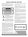 3
3
-
 4
4
-
 5
5
-
 6
6
-
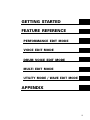 7
7
-
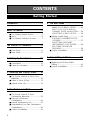 8
8
-
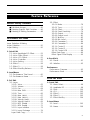 9
9
-
 10
10
-
 11
11
-
 12
12
-
 13
13
-
 14
14
-
 15
15
-
 16
16
-
 17
17
-
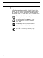 18
18
-
 19
19
-
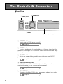 20
20
-
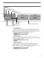 21
21
-
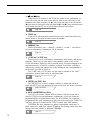 22
22
-
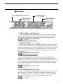 23
23
-
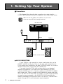 24
24
-
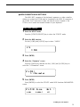 25
25
-
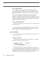 26
26
-
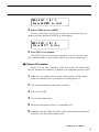 27
27
-
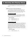 28
28
-
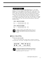 29
29
-
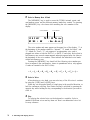 30
30
-
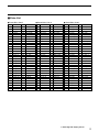 31
31
-
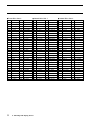 32
32
-
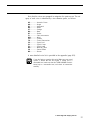 33
33
-
 34
34
-
 35
35
-
 36
36
-
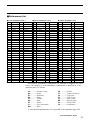 37
37
-
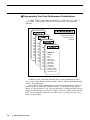 38
38
-
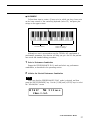 39
39
-
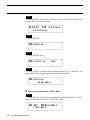 40
40
-
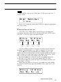 41
41
-
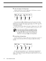 42
42
-
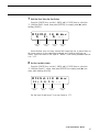 43
43
-
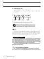 44
44
-
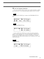 45
45
-
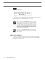 46
46
-
 47
47
-
 48
48
-
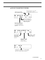 49
49
-
 50
50
-
 51
51
-
 52
52
-
 53
53
-
 54
54
-
 55
55
-
 56
56
-
 57
57
-
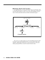 58
58
-
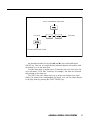 59
59
-
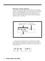 60
60
-
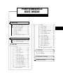 61
61
-
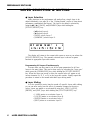 62
62
-
 63
63
-
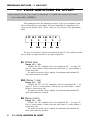 64
64
-
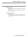 65
65
-
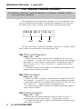 66
66
-
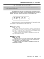 67
67
-
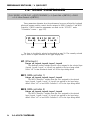 68
68
-
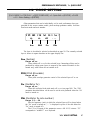 69
69
-
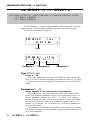 70
70
-
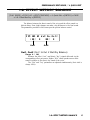 71
71
-
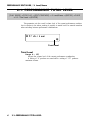 72
72
-
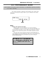 73
73
-
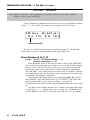 74
74
-
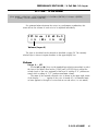 75
75
-
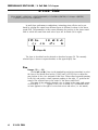 76
76
-
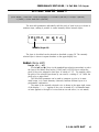 77
77
-
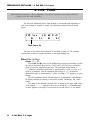 78
78
-
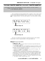 79
79
-
 80
80
-
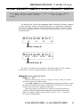 81
81
-
 82
82
-
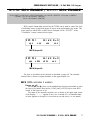 83
83
-
 84
84
-
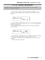 85
85
-
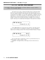 86
86
-
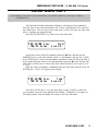 87
87
-
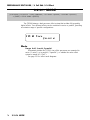 88
88
-
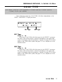 89
89
-
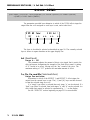 90
90
-
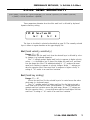 91
91
-
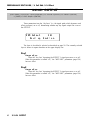 92
92
-
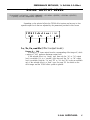 93
93
-
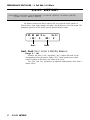 94
94
-
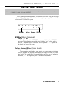 95
95
-
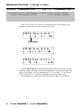 96
96
-
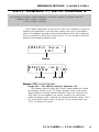 97
97
-
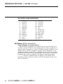 98
98
-
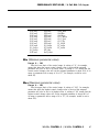 99
99
-
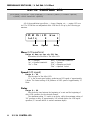 100
100
-
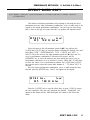 101
101
-
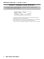 102
102
-
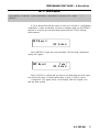 103
103
-
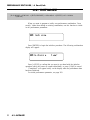 104
104
-
 105
105
-
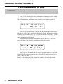 106
106
-
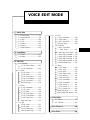 107
107
-
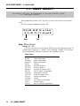 108
108
-
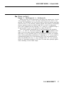 109
109
-
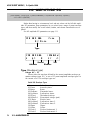 110
110
-
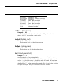 111
111
-
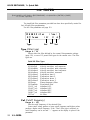 112
112
-
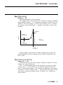 113
113
-
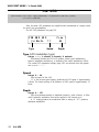 114
114
-
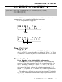 115
115
-
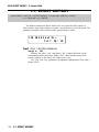 116
116
-
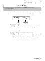 117
117
-
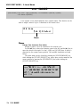 118
118
-
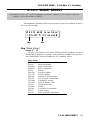 119
119
-
 120
120
-
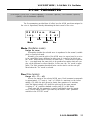 121
121
-
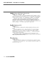 122
122
-
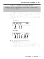 123
123
-
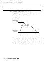 124
124
-
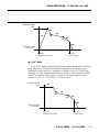 125
125
-
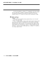 126
126
-
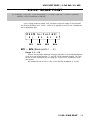 127
127
-
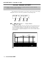 128
128
-
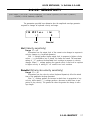 129
129
-
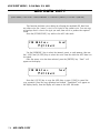 130
130
-
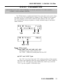 131
131
-
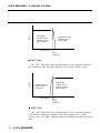 132
132
-
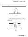 133
133
-
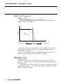 134
134
-
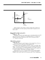 135
135
-
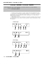 136
136
-
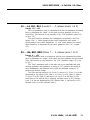 137
137
-
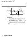 138
138
-
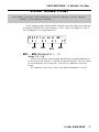 139
139
-
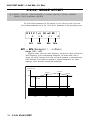 140
140
-
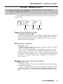 141
141
-
 142
142
-
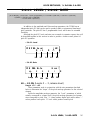 143
143
-
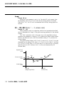 144
144
-
 145
145
-
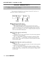 146
146
-
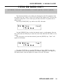 147
147
-
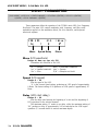 148
148
-
 149
149
-
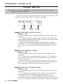 150
150
-
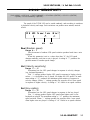 151
151
-
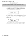 152
152
-
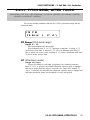 153
153
-
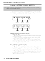 154
154
-
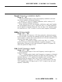 155
155
-
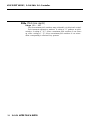 156
156
-
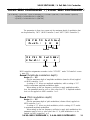 157
157
-
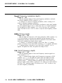 158
158
-
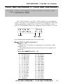 159
159
-
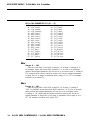 160
160
-
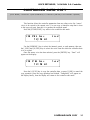 161
161
-
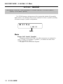 162
162
-
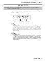 163
163
-
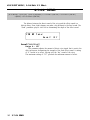 164
164
-
 165
165
-
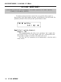 166
166
-
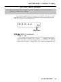 167
167
-
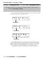 168
168
-
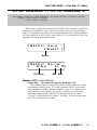 169
169
-
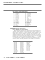 170
170
-
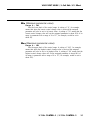 171
171
-
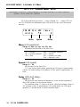 172
172
-
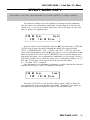 173
173
-
 174
174
-
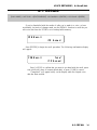 175
175
-
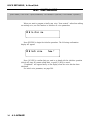 176
176
-
 177
177
-
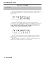 178
178
-
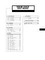 179
179
-
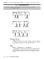 180
180
-
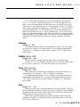 181
181
-
 182
182
-
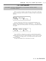 183
183
-
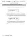 184
184
-
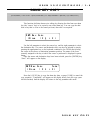 185
185
-
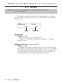 186
186
-
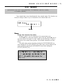 187
187
-
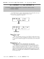 188
188
-
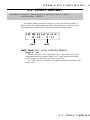 189
189
-
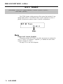 190
190
-
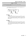 191
191
-
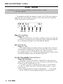 192
192
-
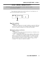 193
193
-
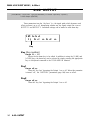 194
194
-
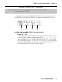 195
195
-
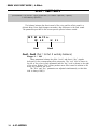 196
196
-
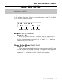 197
197
-
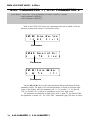 198
198
-
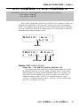 199
199
-
 200
200
-
 201
201
-
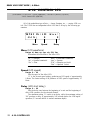 202
202
-
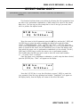 203
203
-
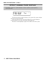 204
204
-
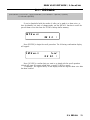 205
205
-
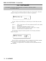 206
206
-
 207
207
-
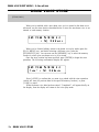 208
208
-
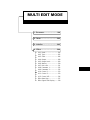 209
209
-
 210
210
-
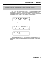 211
211
-
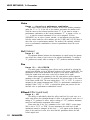 212
212
-
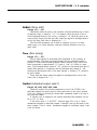 213
213
-
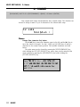 214
214
-
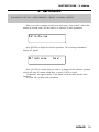 215
215
-
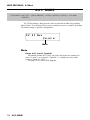 216
216
-
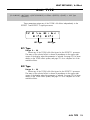 217
217
-
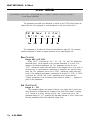 218
218
-
 219
219
-
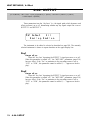 220
220
-
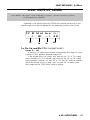 221
221
-
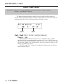 222
222
-
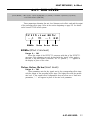 223
223
-
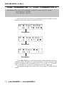 224
224
-
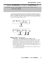 225
225
-
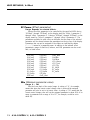 226
226
-
 227
227
-
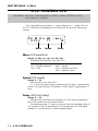 228
228
-
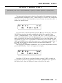 229
229
-
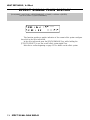 230
230
-
 231
231
-
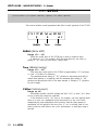 232
232
-
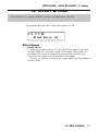 233
233
-
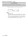 234
234
-
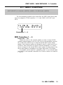 235
235
-
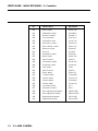 236
236
-
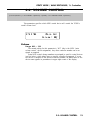 237
237
-
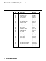 238
238
-
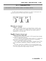 239
239
-
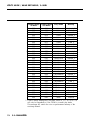 240
240
-
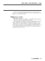 241
241
-
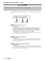 242
242
-
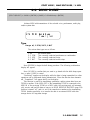 243
243
-
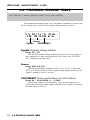 244
244
-
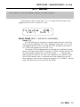 245
245
-
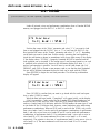 246
246
-
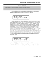 247
247
-
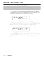 248
248
-
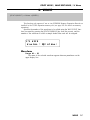 249
249
-
 250
250
-
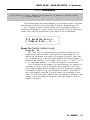 251
251
-
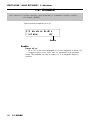 252
252
-
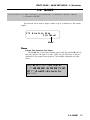 253
253
-
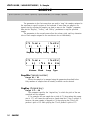 254
254
-
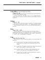 255
255
-
 256
256
-
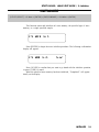 257
257
-
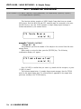 258
258
-
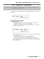 259
259
-
 260
260
-
 261
261
-
 262
262
-
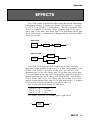 263
263
-
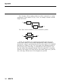 264
264
-
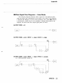 265
265
-
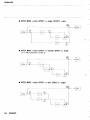 266
266
-
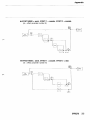 267
267
-
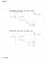 268
268
-
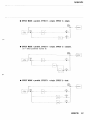 269
269
-
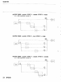 270
270
-
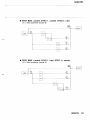 271
271
-
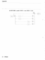 272
272
-
 273
273
-
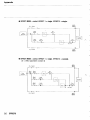 274
274
-
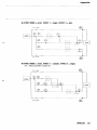 275
275
-
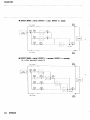 276
276
-
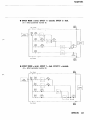 277
277
-
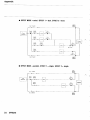 278
278
-
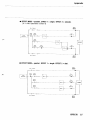 279
279
-
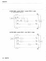 280
280
-
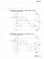 281
281
-
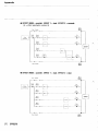 282
282
-
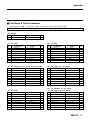 283
283
-
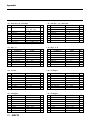 284
284
-
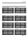 285
285
-
 286
286
-
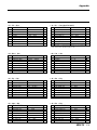 287
287
-
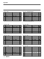 288
288
-
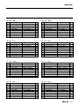 289
289
-
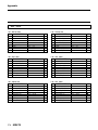 290
290
-
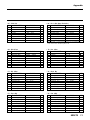 291
291
-
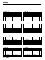 292
292
-
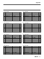 293
293
-
 294
294
-
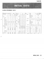 295
295
-
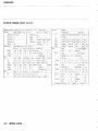 296
296
-
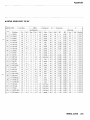 297
297
-
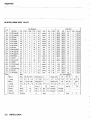 298
298
-
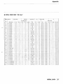 299
299
-
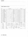 300
300
-
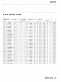 301
301
-
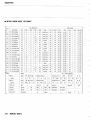 302
302
-
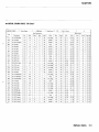 303
303
-
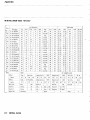 304
304
-
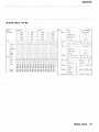 305
305
-
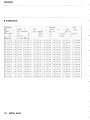 306
306
-
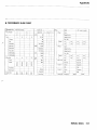 307
307
-
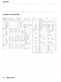 308
308
-
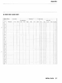 309
309
-
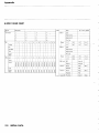 310
310
-
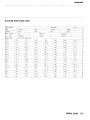 311
311
-
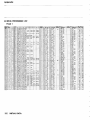 312
312
-
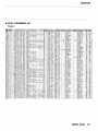 313
313
-
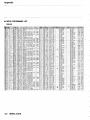 314
314
-
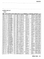 315
315
-
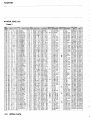 316
316
-
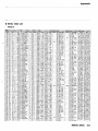 317
317
-
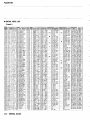 318
318
-
 319
319
-
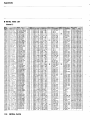 320
320
-
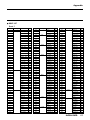 321
321
-
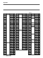 322
322
-
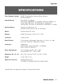 323
323
-
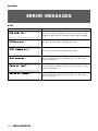 324
324
-
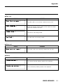 325
325
-
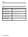 326
326
-
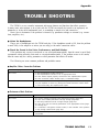 327
327
-
 328
328
-
 329
329
-
 330
330
-
 331
331
-
 332
332
-
 333
333
-
 334
334


Yamaha TG500 Manual de usuario
- Categoría
- Instrumentos musicales
- Tipo
- Manual de usuario
En otros idiomas
- français: Yamaha TG500 Manuel utilisateur
- italiano: Yamaha TG500 Manuale utente
- English: Yamaha TG500 User manual
- Deutsch: Yamaha TG500 Benutzerhandbuch
- русский: Yamaha TG500 Руководство пользователя
- Nederlands: Yamaha TG500 Handleiding
- português: Yamaha TG500 Manual do usuário
- dansk: Yamaha TG500 Brugermanual
- polski: Yamaha TG500 Instrukcja obsługi
- čeština: Yamaha TG500 Uživatelský manuál
- svenska: Yamaha TG500 Användarmanual
- Türkçe: Yamaha TG500 Kullanım kılavuzu
- suomi: Yamaha TG500 Ohjekirja
- română: Yamaha TG500 Manual de utilizare
Documentos relacionados
-
Yamaha SY85 Manual de usuario
-
Yamaha CS6R El manual del propietario
-
Yamaha Card Filer Manual de usuario
-
-
-
Yamaha ES6 Manual de usuario
-
-
-
-
