
1Modern Forms retains the right to modify the design of our products at any time as part of the company's continuous improvement program.
modernforms.com
Phone (800) 526.2588
Fax (800) 526.2585
Headquarters/Eastern Distribution Center
44 Harbor Park Drive
Port Washington, NY 11050
Central Distribution Center
1600 Distribution Ct
Lithia Springs, GA 30122
Western Distribution Center
1750 Archibald Avenue
Ontario, CA 91760
INSTALLATION INSTRUCTION
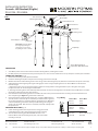
417 - LED Pendant
PD-41703L / PD-41803L
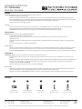
Wire Connector Junction Box Screw Mounting Screw Wood Screw Plastic Anchor
Qty: 3 pcs + 1 Extra Qty: 2 pcs + 1 Extra Qty: 1 Extra Qty: 2 pcs + 1 Extra Qty: 2 pcs + 1 Extra
A B C D E
WARNING
IMPORTANT: NEVER attempt any work without shutting o the electricity.
- Read all instructions before installing.
- System is intended for installation by a qualied electrician in accordance with the National Electrical Code and local regulations.
- Go to the main fuse box, or circuit breaker. Place the main power switch in the “OFF” position and unscrew the fuse(s) or switch ”OFF”
the circuit breaker switch(es) that control the power to the xture or room that you are working on.
- Place the wall switch in the “OFF” position.
CAUTION
- All parts must be used as indicated in these instructions. Do not substitute any parts, leave parts out, or use any parts that are
worn out or broken. Failure to follow this instruction could invalidate the ETL/CETL listing of this xture.
CAUTION When handling the xture, do not apply pressure to the LEDs. Hold the xture by the base only.
AVERTISSEMENT
IMPORTANT : Coupez l’électricité avant TOUTE manipulation.
- Lisez toutes les instructions avant d’installer.
- Système est destiné à être installé par un électricien qualié en conformité avec le code national de l’électricité et les
règlements locaux.
- Accédez au panneau central de disjoncteurs ou de fusibles de votre demeure et placez l’interrupteur principal en position d’arrêt
(« OFF »).
- Placez l’interrupteur mural en position d’arrêt (« OFF »).
MISE EN GARDE
- Toutes les pièces doivent être utilisées tel qu’il est indiqué dans ces instructions. Ne remplacez pas les pièces, n’en laissez pas de côté
et ne les utilisez pas si elles sont usées ou brisées. Le non-respect de ces instructions peut annuler l’homologation ETL/CETL du
luminaire. MISE EN GARDE Ors de la manipulation de l’appareil, ne pas appliquer de pression à la LED, tenir l’appareil par la seule base.
ADVERTENCIA
IMPORTANTE: NUNCA intente hacer trabajos sin desconectar el suministro eléctrico.
- Lea y comprenda todas las instrucciones e ilustraciones por completo antes de proceder con el ensamblaje e insta lación de esta
lámpara.
- Sistema está disenado para ser instalado por un electricista calicado, de acuerdo con el código eléctrico nacional y las normas locales.
- Diríjase a la caja de fusibles o a la caja del interruptor de circuito principal en su hogar. Coloque el interruptor de ali mentación
principal en la posición “OFF” (APAGADO).
- Coloque el interruptor de la pared en la posición “OFF” (APAGADO).
PRECAUCIÓN
- Todas las piezas deben usarse como lo indican estas instrucciones. No reemplace las piezas, noomita piezas durante la instalación ni
utilice piezas gastadas o rotas. El incumplimiento de esta indicación podría invalidar la calicación
ETL/CETL esta lámpara. PRECAUCIÓN Al manipular el aparato, no aplique presión a los LED, mantenga el aparato en la base sólo.
HARDWARE
G2

2Modern Forms retains the right to modify the design of our products at any time as part of the company's continuous improvement program.
modernforms.com
Phone (800) 526.2588
Fax (800) 526.2585
Headquarters/Eastern Distribution Center
44 Harbor Park Drive
Port Washington, NY 11050
Central Distribution Center
1600 Distribution Ct
Lithia Springs, GA 30122
Western Distribution Center
1750 Archibald Avenue
Ontario, CA 91760
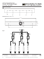
Fig. 2 Wiring
Fixture Wires House Wires
Black or Black
Smooth (Hot)
Fixture Wires House Wires
White or White
Ribbed (Neutral)
Fixture Wires House Wires
Bare wire Green or Bare Copper
(Ground) (Ground)
8. Connect the driver input wires with supply wires as shown in Fig. 2, making
sure that all wire connectors (A) are secured.If your outlet box has a green or
bare copper ground wire, connect the fixture’s ground wire to it. Otherwise,
connect the fixture’s ground wire directly to themounting plate using the
green screw provided. After wires are connected, tuck them carefully inside
the junction box.
A
B
E
D
C
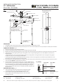
FIG. 1 Back Plate Dimensions
(#7MBC901002)
1 3/8"
1 3/4"
35 3/8"
4 1/8"
27 5/8"
Junction Box Screw
Plastic Anchor
Wood Screw
Mounting Screw
Cable Gripper
Lamp Body
Crystal Glass
(RPL-GLA-41719)
Junction Box
Ground Wire
Wire Connector
Mounting Back Plate
INSTALLATION INSTRUCTION
417 - LED Pendant
PD-41703L / PD-41803L
PREPARATION
1. Shut off the power at the circuit breaker and remove existing fixture, including the crossbar.
2. Carefully unpack your new fixture and lay out all the parts on a clear area. Be careful not to lose any small parts necessary for installation.
CONNECTING THE WIRES (Fig. 2)
3. Remove the mounting screws (C) from the fixture.
4. Install the mounting back plate to the junction box using junction box screws (B)
5. Mark the two wood screw mounting holes on the ceiling, remove mounting back plate, drill holes and insert the two plastic anchors (E)
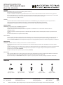
6. Adjust the fixture wire length by pushing the cable gripper on the canopy and pulling the wire as desired. Make sure the wires are
the same length.
a. Retract these wires close to a desirable length to within the canopy before securing the fixture in place. Using the cable gripper
to adjust more than 18” of wire length is not desirable.
b. Warning: Shortening these cables without professional helps or electronic background is not advisable. Any modifications to the
fixture will result in voiding the warranty of the product.
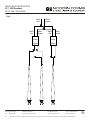
7. Please follow these if shortening the wire is needed. Take note or take picture of how the wires are being connected and label each wire
clearly. Using the figure 3 as given below as reference.
Push up
Cable-gripper
Instruction: Adjust the xture
wire length by pushing the
cable gripper on the canopy
and pulling the wire as desired.
Acrylic (RPL-GLA-41819)
G2
Driver
3” L x 1 1/4” W x 1 1/8” H
MOUNTING THE FIXTURE (Fig. 1)
Install mounting plate back to the junction box using junction box
screws (B), fasten it to the ceiling using the two wood screws (D).
The side of the mounting plate marked “GND” must face out.
9.
Push the xture onto the mounting back plate, and secure it with
mounting screws (C).
10.

3
Modern Forms retains the right to modify the design of our products at any time as part of the company's continuous improvement program.
modernforms.com
Phone (800) 526.2588
Fax (800) 526.2585
Headquarters/Eastern Distribution Center
44 Harbor Park Drive
Port Washington, NY 11050
Central Distribution Center
1600 Distribution Ct
Lithia Springs, GA 30122
Western Distribution Center
1750 Archibald Avenue
Ontario, CA 91760
INSTALLATION INSTRUCTION
417 - LED Pendant
PD-41703L / PD-41803L
G2
Driver
I
nput
Out
put
Black
- Hot
White -
Neutral
Driver
I
nput
Out
put
Black
- Hot White -
Neutral
-+-+
Black
- Hot White -
Neutral
Fig. 3

Modern Forms retains the right to modify the design of our products at any time as part of the company's continuous improvement program.
modernforms.com
Phone (800) 526.2588
Fax (800) 526.2585
Headquarters/Eastern Distribution Center
44 Harbor Park Drive
Port Washington, NY 11050
Central Distribution Center
1600 Distribution Ct
Lithia Springs, GA 30122
Western Distribution Center
1750 Archibald Avenue
Ontario, CA 91760
INSTALLATION INSTRUCTION
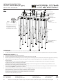
Cascade - LED Pendant (5 Lights)
PD-41705L / PD-41805L
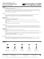
Wire Connector
Qty: 3 pcs + 1 Extra
Junction Box Screw
Qty: 2 pcs + 1 Extra
Wood Screw
Qty: 2 pcs + 1 Extra
Plastic Anchor
Qty: 2 pcs + 1 Extra
A B C D E
WARNING
IMPORTANT: NEVER attempt any work without shutting o the electricity.
- Read all instructions before installing.
- System is intended for installation by a qualied electrician in accordance with the National Electrical Code and local regulations.
- Go to the main fuse box, or circuit breaker. Place the main power switch in the “OFF” position and unscrew the fuse(s) or switch ”OFF”
the circuit breaker switch(es) that control the power to the xture or room that you are working on.
- Place the wall switch in the “OFF” position.
CAUTION
- All parts must be used as indicated in these instructions. Do not substitute any parts, leave parts out, or use any parts that are
worn out or broken. Failure to follow this instruction could invalidate the ETL/CETL listing of this xture.
CAUTION When handling the xture, do not apply pressure to the LEDs. Hold the xture by the base only.
AVERTISSEMENT
IMPORTANT : Coupez l’électricité avant TOUTE manipulation.
- Lisez toutes les instructions avant d’installer.
- Système est destiné à être installé par un électricien qualié en conformité avec le code national de l’électricité et les
règlements locaux.
- Accédez au panneau central de disjoncteurs ou de fusibles de votre demeure et placez l’interrupteur principal en position d’arrêt
(« OFF »).
- Placez l’interrupteur mural en position d’arrêt (« OFF »).
MISE EN GARDE
- Toutes les pièces doivent être utilisées tel qu’il est indiqué dans ces instructions. Ne remplacez pas les pièces, n’en laissez pas de côté
et ne les utilisez pas si elles sont usées ou brisées. Le non-respect de ces instructions peut annuler l’homologation ETL/CETL du
luminaire. MISE EN GARDE Ors de la manipulation de l’appareil, ne pas appliquer de pression à la LED, tenir l’appareil par la seule base.
ADVERTENCIA
IMPORTANTE: NUNCA intente hacer trabajos sin desconectar el suministro eléctrico.
- Lea y comprenda todas las instrucciones e ilustraciones por completo antes de proceder con el ensamblaje e insta lación de esta
lámpara.
- Sistema está disenado para ser instalado por un electricista calicado, de acuerdo con el código eléctrico nacional y las normas locales.
- Diríjase a la caja de fusibles o a la caja del interruptor de circuito principal en su hogar. Coloque el interruptor de ali mentación
principal en la posición “OFF” (APAGADO).
- Coloque el interruptor de la pared en la posición “OFF” (APAGADO).
PRECAUCIÓN
- Todas las piezas deben usarse como lo indican estas instrucciones. No reemplace las piezas, noomita piezas durante la instalación ni
utilice piezas gastadas o rotas. El incumplimiento de esta indicación podría invalidar la calicación
ETL/CETL esta lámpara. PRECAUCIÓN Al manipular el aparato, no aplique presión a los LED, mantenga el aparato en la base sólo.
HARDWARE
Mounting Screw
Qty: 1 Extra
1G3

Modern Forms retains the right to modify the design of our products at any time as part of the company's continuous improvement program.
modernforms.com
Phone (800) 526.2588
Fax (800) 526.2585
Headquarters/Eastern Distribution Center
44 Harbor Park Drive
Port Washington, NY 11050
Central Distribution Center
1600 Distribution Ct
Lithia Springs, GA 30122
Western Distribution Center
1750 Archibald Avenue
Ontario, CA 91760
INSTALLATION INSTRUCTION
Cascade - LED Pendant (5 Lights)
PD-41705L / PD-41805L
Junction Box Screw
Plastic Anchor
Wood Screw
Mounting Screw
Cable Gripper
Lamp Body
Acrylic (RPL-GLA-41819)
Crystal Glass (RPL-GLA-41719)
Junction Box
Ground Wire
Wire Connector
Mounting Back Plate
Cable Gripper Push up
B
E
D
C
A
FIG. 1
Instruction: Adjust the xture
wire length by pushing the
cable gripper on the canopy
and pulling the wire as desired.
2
G3
Driver
3” L x 1 1/4” W x 1 1/8” H
1. Shut off the power at the circuit breaker and remove existing fixture, including the crossbar.
2. Carefully unpack your new fixture and lay out all the parts on a clear area. Be careful not to lose any small parts necessary for installation.
CONNECTING THE WIRES (Fig. 2)
3. Remove the mounting screws (C) from the fixture.
4. Install the mounting back plate to the junction box using junction box screws (B)
5. Mark the two wood screw mounting holes on the ceiling, remove mounting back plate, drill holes and insert the two plastic anchors (E)
6. Adjust the fixture wire length by pushing the cable gripper on the canopy and pulling the wire as desired. Make sure the wires are
the same length.
a. Retract these wires close to a desirable length to within the canopy before securing the fixture in place. Using the cable gripp
to adjust more than 18” of wire length is not desirable.
7.
Fixture Wires House Wires
Black or Black
Smooth (Hot)
Fixture Wires House Wires
White or White
Ribbed (Neutral)
Fixture Wires
Bare wire
(Ground)
House Wires
Green or Bare Copper
(Ground)
8.
b. Warning: Shortening these cables without professional helps or electronic background is not advisable. Any modifications to t fixture
will result in voiding the warranty of the product.
Please follow these if shortening the wire is needed. Take note or take picture of how the wires are being connected and label each
wire clearly.Using the figure 4 as given below as reference.
Connect the driver input wires with supply wires as shown in Fig. 2, making Fig. 2 Wiring
sure that all wire connectors (A) are secured.If your outlet box has a green or
bare copper ground wire, connect the fixture’s ground wire to it. Otherwise,
connect the fixture’s ground wire directly to themounting plate using the
green screw provided. After wires are connected, tuck them carefully inside
the junction box.
PREPARATION
MOUNTING THE FIXTURE (Fig. 1)
9. Install mounting plate back to the junction box using junction box
screws (B), fasten it to the ceiling using the two wood screws (D).
The side of the mounting plate marked “GND” must face out.
Push the xture onto the mounting back plate, and secure it with
mounting screws (C).
10.

Modern Forms retains the right to modify the design of our products at any time as part of the company's continuous improvement program.
modernforms.com
Phone (800) 526.2588
Fax (800) 526.2585
Headquarters/Eastern Distribution Center
44 Harbor Park Drive
Port Washington, NY 11050
Central Distribution Center
1600 Distribution Ct
Lithia Springs, GA 30122
Western Distribution Center
1750 Archibald Avenue
Ontario, CA 91760
Back Plate Dimensions (#7MBC901002)
27 5/8"
35 3/8"
1 3/4"
1 3/8"
4 1/8"
43"49"49" 43"
43"
INSTALLATION INSTRUCTION
Cascade - LED Pendant (5 Lights)
PD-41705L / PD-41805L
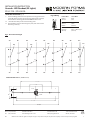
Fig 3: Recommended length
3G3
Driver
I
nput
Out
put
Black
- Hot
White -
Neutral
Driver
I
nput
Out
put
Black
- Hot
White -
Neutral
-+-+
Black
- Hot
White -
Neutral
Driver
I
nput
Out
put
Black
- Hot
White -
Neutral
-+
Fig. 4

Modern Forms retains the right to modify the design of our products at any time as part of the company's continuous improvement program.
modernforms.com
Phone (800) 526.2588
Fax (800) 526.2585
Headquarters/Eastern Distribution Center
44 Harbor Park Drive
Port Washington, NY 11050
Central Distribution Center
1600 Distribution Ct
Lithia Springs, GA 30122
Western Distribution Center
1750 Archibald Avenue
Ontario, CA 91760
INSTALLATION INSTRUCTION
Cascade - LED Pendant (23 Lights)
PD-41723L / PD-41823L
Mounting Screw
Wire Connector
Qty: 3 pcs + 1 Extra
Plastic Anchor
Qty: 8 pcs + 1 Extra
Junction Box Screw
Qty: 2 pcs + 1 Extra
Wood Screw
Qty: 8 pcs + 1 Extra
A B C D E
WARNING
IMPORTANT: NEVER attempt any work without shutting o the electricity.
- Read all instructions before installing.
- System is intended for installation by a qualied electrician in accordance with the National Electrical Code and local regulations.
- Go to the main fuse box, or circuit breaker. Place the main power switch in the “OFF” position and unscrew the fuse(s) or switch ”OFF”
the circuit breaker switch(es) that control the power to the xture or room that you are working on.
- Place the wall switch in the “OFF” position.
CAUTION
- All parts must be used as indicated in these instructions. Do not substitute any parts, leave parts out, or use any parts that are
worn out or broken. Failure to follow this instruction could invalidate the ETL/CETL listing of this xture.
CAUTION When handling the xture, do not apply pressure to the LEDs. Hold the xture by the base only.
AVERTISSEMENT
IMPORTANT : Coupez l’électricité avant TOUTE manipulation.
- Lisez toutes les instructions avant d’installer.
- Système est destiné à être installé par un électricien qualié en conformité avec le code national de l’électricité et les
règlements locaux.
- Accédez au panneau central de disjoncteurs ou de fusibles de votre demeure et placez l’interrupteur principal en position d’arrêt
(« OFF »).
- Placez l’interrupteur mural en position d’arrêt (« OFF »).
MISE EN GARDE
- Toutes les pièces doivent être utilisées tel qu’il est indiqué dans ces instructions. Ne remplacez pas les pièces, n’en laissez pas de côté
et ne les utilisez pas si elles sont usées ou brisées. Le non-respect de ces instructions peut annuler l’homologation ETL/CETL du
luminaire. MISE EN GARDE Ors de la manipulation de l’appareil, ne pas appliquer de pression à la LED, tenir l’appareil par la seule base.
ADVERTENCIA
IMPORTANTE: NUNCA intente hacer trabajos sin desconectar el suministro eléctrico.
- Lea y comprenda todas las instrucciones e ilustraciones por completo antes de proceder con el ensamblaje e insta lación de esta
lámpara.
- Sistema está disenado para ser instalado por un electricista calicado, de acuerdo con el código eléctrico nacional y las normas locales.
- Diríjase a la caja de fusibles o a la caja del interruptor de circuito principal en su hogar. Coloque el interruptor de ali mentación
principal en la posición “OFF” (APAGADO).
- Coloque el interruptor de la pared en la posición “OFF” (APAGADO).
PRECAUCIÓN
- Todas las piezas deben usarse como lo indican estas instrucciones. No reemplace las piezas, noomita piezas durante la instalación ni
utilice piezas gastadas o rotas. El incumplimiento de esta indicación podría invalidar la calicación
ETL/CETL esta lámpara. PRECAUCIÓN Al manipular el aparato, no aplique presión a los LED, mantenga el aparato en la base sólo.
HARDWARE
Qty: 1 Extra
1
G3

Modern Forms retains the right to modify the design of our products at any time as part of the company's continuous improvement program.
modernforms.com
Phone (800) 526.2588
Fax (800) 526.2585
Headquarters/Eastern Distribution Center
44 Harbor Park Drive
Port Washington, NY 11050
Central Distribution Center
1600 Distribution Ct
Lithia Springs, GA 30122
Western Distribution Center
1750 Archibald Avenue
Ontario, CA 91760
PREPARATION
1. Shut o the power at the circuit breaker and remove existing xture, including the crossbar.
2. Carefully unpack your new xture and lay out all the parts on a clear area. Be careful not to lose any small parts necessary for installation.
CONNECTING THE WIRES (Fig. 2)
INSTALLATION INSTRUCTION
Cascade - LED Pendant (23 Lights)
PD-41723L / PD-41823L
Plastic Anchor
Junction Box Screw
Wood Screw
Mounting Screw
Cable Gripper
Safety Cable
Mounting Back Plate
Junction Box
Ground Wire
Wire
Connector
Lamp Body
Crystal Glass
(RPL-GLA-41719)
E
B
D
C
A
FIG. 1
Cable
gripper Push up
Instruction: Adjust the xture
wire length by pushing the
cable gripper on the canopy
and pulling the wire as desired.
3. Remove the mounting screws (C) from the fixture.
4. Install the mounting back plate to the junction box using junction box screws (B)
5. Mark the eight wood screw mounting holes on the ceiling, remove mounting back plate, drill holes and insert the eight plastic anchors (E)
6. Adjust the fixture wire length by pushing the cable gripper on the canopy and pulling the wire as desired.Make sure the wires are
the same length.
a. Retract these wires close to a desirable length to within the canopy before securing the fixture in place. Using the cable gripper
to adjust more than 18” of wire length is not desirable.
b. Warning: Shortening these cables without professional helps or electronic background is not advisable. Any modifications to the
fixture will result in voiding the warranty of the product.
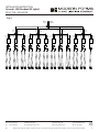
7. Please follow these if shortening the wire is needed. Take note or take picture of how the wires are being connected and label each wire
clearly. Using the figure 4 as given below as reference.
8. Connect the driver input wires with supply wires as shown in Fig. 2, making sure that all wire connectors (A) are secured.
If your outlet box has a green or bare copper ground wire, connect the fixture’s
ground wire to it. Otherwise, connect the fixture’s ground wire directly to the
mounting plate using the green screw provided. After wires are connected,
tuck them carefully inside the junction box.
2
Acrylic (RPL-GLA-41819)
G3
Driver
3” L x 1 1/4” W x 1 1/8” H

11. Push the xture onto the mounting back plate, and secure it with
10. Hook the two safety cords to the mounting plate
Modern Forms retains the right to modify the design of our products at any time as part of the company's continuous improvement program.
modernforms.com
Phone (800) 526.2588
Fax (800) 526.2585
Headquarters/Eastern Distribution Center
44 Harbor Park Drive
Port Washington, NY 11050
Central Distribution Center
1600 Distribution Ct
Lithia Springs, GA 30122
Western Distribution Center
1750 Archibald Avenue
Ontario, CA 91760
Back Plate Dimensions (#7MBC102701)
11 3/4"
1 3/4"
1 3/8"
27 7/8"
41 3/8"
35 3/8"
7 1/8"
11"
INSTALLATION INSTRUCTION
Cascade - LED Pendant (23 Lights)
PD-41723L / PD-41823L
Fig.3: Recommended length
39" 32"
31" 47" 42" 43" 44" 39" 49" 29"35"
52" 57" 36"
50"
46" 43" 35" 41"
51"55"
28"
55"
MOUNTING THE FIXTURE (Fig. 1)
9.Install mounting plate back to the junction box using junction box
screws (B), fasten it to the ceiling using the eight wood screws (D).
The side of the mounting plate marked “GND” must face out.
mounting screws (C).
Fixture Wires
Black or
Smooth
Fixture Wires
White or
Ribbed
Fixture Wires
Bare wire
(Ground)
House Wires
Black
(Hot)
House Wires
White
(Neutral)
House Wires
Green or Bare Copper
(Ground)
Fig. 2 Wiring
3G3

Modern Forms retains the right to modify the design of our products at any time as part of the company's continuous improvement program.
modernforms.com
Phone (800) 526.2588
Fax (800) 526.2585
Headquarters/Eastern Distribution Center
44 Harbor Park Drive
Port Washington, NY 11050
Central Distribution Center
1600 Distribution Ct
Lithia Springs, GA 30122
Western Distribution Center
1750 Archibald Avenue
Ontario, CA 91760
INSTALLATION INSTRUCTION
Cascade - LED Pendant (23 Lights)
PD-41723L / PD-41823L
4
G3
Driver
I
nput
Out
put
Black
- Hot
White -
Neutral
-+
Driver
I
nput
Out
put
Black
- Hot
White -
Neutral
-+
Driver
I
nput
Out
put
Black
- Hot
White -
Neutral
-+
Black
- Hot
White -
Neutral
Black
- Hot
White -
Neutral
Driver
I
nput
Out
put
Black
- Hot
White -
Neutral
-+
Driver
I
nput
Out
put
Black
- Hot
White -
Neutral
-+
Driver
I
nput
Out
put
Black
- Hot
White -
Neutral
-+
Black
- Hot
White -
Neutral
Driver
I
nput
Out
put
Black
- Hot
White -
Neutral
-+
Driver
I
nput
Out
put
Black
- Hot
White -
Neutral
-+
Driver
I
nput
Out
put
Black
- Hot
White -
Neutral
-+
Black
- Hot
White -
Neutral
Driver
I
nput
Out
put
Black
- Hot
White -
Neutral
-+
Driver
I
nput
Out
put
Black
- Hot
White -
Neutral
-+
Driver
I
nput
Out
put
Black
- Hot
White -
Neutral
-+
Black
- Hot
White -
Neutral
Fig. 4
-
 1
1
-
 2
2
-
 3
3
-
 4
4
-
 5
5
-
 6
6
-
 7
7
-
 8
8
-
 9
9
-
 10
10


Modern Forms PD-41803L Cascade Instrucciones de operación
- Tipo
- Instrucciones de operación
- Este manual también es adecuado para
en otros idiomas
Artículos relacionados
-
Modern Forms WS-84819 Stem Instrucciones de operación
-
-
-
-
-
-
-
-
-
