jbc PHNEK Preheater Set El manual del propietario
- Tipo
- El manual del propietario

MANUAL DE INSTRUCCIONES
PHNEK
Set Precalentador para PCB
de hasta 11x7cm

2
Termopar ............. 2 unidades
Ref. PH218
Cinta Kapton ........... 1 unidad
Ref. PH217
Manual ...................... 1 unidad
Ref. 0032768
Soporte para PCB nano ....................1 unidad
Ref. PHN-SA
Unidad precalentadora nano .........1 unidad
Consola ..................... 1 unidad
Ref. ACE-A
Cable de red .............1 unidad
Ref. 0023714 (230V)
Cable RJ45 .............. 1 unidad
Ref. 0019914
Composición
Compruebe que los artículos listados a continuación están incluidos:
Este manual corresponde a las referencia siguiente:
PHNE-2KA (230V)

PHXLE
PHXL-SA
PHB-SA
PHS-SA
PHN-SA
PHBE DESPIECE PHB
PHSE
PHNE
OK
14:15
20ºC
Power
45%
TC1
45ºC
Selected 120ºC
TC2
P100ºC
20ºC
TC3
P100ºC
20ºC
TC4
P100ºC
14:15
20ºC
Power
45%
Selected power
45%
TC1
P100ºC
20ºC
TC3
P100ºC
20ºC
TC4
P100ºC
20ºC
TC2
P100ºC
14:15
20 ºC
T1 23 ºC
20
5’ 8’
ºC
120 ºC
T3
24 ºC
T7
StopPROFILE1
200
100
14:15
31ºC27ºC
TC1 TC2
StopPROFILE1
200
100
14:15
200
150
100
50
300
250
14:15
5m 00s
120ºC
PROFILE1
200
100
14:15
30ºC
Power
45%
Selected power
45%
TC1
C100ºC
---ºC
TC2
P100ºC
0 60 120 180 240 300
Point
2/3
Temp Time
2m 00s
14:15
20ºC20 ºC
TC1 TC2
20ºC
TC3
20ºC
TC4
StopPROFILE1
200
100
Ext. Temp [ºC]Power [%]
14:15
20ºC
Power
45%
TC1
45ºC
Selected 120ºC
TC2
P100ºC
20ºC
TC3
P100ºC
20ºC
TC4
P100ºC
14:15
20ºC
Power
45%
TC1
45ºC
Selected 120ºC
Max. Rate
1.6ºC/s
Max. Rate
1.6ºC/s
TC2
C100ºC
20ºC
TC3
P100ºC
20ºC
TC4
P100ºC
14:15
20ºC
Power
45%
Selected power
45%
14:15
TC5
P100ºC
20ºC
TC7
P100ºC
20ºC
TC8
P100ºC
20ºC
TC6
P100ºC
20ºC
TC5
P100ºC
14:15
20ºC
Power
45%
TC1
25ºC
Selected 120ºC
TC2
P100ºC
14:15
20ºC
Power
45%
TC1
25ºC
Selected 120ºC
TC2
P100ºC
14:15
20ºC
Power
45%
TC1
45ºC
Selected 120ºC
TC2
C100ºC
20ºC
TC3
P100ºC
20ºC
TC4
P100ºC
20ºC
TC5
P100ºC
20
5’ 8’
ºC
120 ºC
80 ºC
100 ºC
5’ 8’5’30”3’30” 8’
20 ºC
120 ºC
80 ºC
TC1 TC2 TC3 TC4
ROBOT AUX. PEDAL
Hot
Zone B
Zone A
Zone A
Zone B
Hot
Hot
Zone B
Zone A
Zone A
Zone B
Hot
TC1 TC2 TC3 TC4
ROBOT AUX. PEDAL
detalle parte trasera
TC1 TC2 TC3 TC4
ROBOT AUX. PEDAL
TC1 TC2 TC3 TC4
ROBOT AUX. PEDAL
Hot
Zone B
Zone A
Zone A
Zone B
Hot
Hot
Zone B
Hot
Zone B
Zone A
Zone A
Max. Rate
1.6ºC/s
Max. Rate
1.6ºC/s
Max. Rate
1.6ºC/s
Max. Rate
1.6ºC/s
Work mode
Mode
Time to stop
Thermocouples
Max Rate
Back
None
2min
Temp.
14:15
Work mode
Mode
Time to stop
Thermocouples
Max Rate
Back
None
2min
Temp.
1.6ºC/s
Max Rate
Min 0.1ºC/s Max 2.0ºC/s
3
40 mm
50 mm
60 mm
80 mm
100 mm
130 mm 130 mm
para manuales - color gris
200 mm
300 mm
Conector ESD
(conectar al punto
de conexión a tierra
común ESD)
Pomos de
abrazaderas
Conector protección
ESD
Características y conexiones
Conector para pedal
Área Calefactora
Toma de corriente
Interruptor
Pomo de fijación
del soporte nano
para PCB
Unidad precalentadora
Consola
Pantalla
Encender / Apagar
Conector USB-B
Conector RJ45
Conector USB-A
Pie para posición
vertical
Botón para
plegado y
desplegado de pie
Conector USB-B
Conector RJ45
Conectores
para termopares
(Tipo K)
Pomos guía
corredera
Guía
corredera
Guía con resorte
Llave Allen
Soporte
Indicador LED de estado:
·Azul: Listo para uso
·Verde: En uso
·Rojo: Error del sistema
Tapones de
goma
Abrazaderas
ranuradas
Dimensiones máx. PCB (entre las abrazaderas):
11x7 cm, Grosor 6 mm
Fusible (en el
interior)

PHXLE
PHXL-SA
PHB-SA
PHS-SA
PHN-SA
PHBE DESPIECE PHB
PHSE
PHNE
OK
14:15
20ºC
Power
45%
TC1
45ºC
Selected 120ºC
TC2
P100ºC
20ºC
TC3
P100ºC
20ºC
TC4
P100ºC
14:15
20ºC
Power
45%
Selected power
45%
TC1
P100ºC
20ºC
TC3
P100ºC
20ºC
TC4
P100ºC
20ºC
TC2
P100ºC
14:15
20 ºC
T1 23 ºC
20
5’ 8’
ºC
120 ºC
T3
24 ºC
T7
StopPROFILE1
200
100
14:15
31ºC27ºC
TC1 TC2
StopPROFILE1
200
100
14:15
200
150
100
50
300
250
14:15
5m 00s
120ºC
PROFILE1
200
100
14:15
30ºC
Power
45%
Selected power
45%
TC1
C100ºC
---ºC
TC2
P100ºC
0 60 120 180 240 300
Point
2/3
Temp Time
2m 00s
14:15
20ºC20 ºC
TC1 TC2
20ºC
TC3
20ºC
TC4
StopPROFILE1
200
100
Ext. Temp [ºC]Power [%]
14:15
20ºC
Power
45%
TC1
45ºC
Selected 120ºC
TC2
P100ºC
20ºC
TC3
P100ºC
20ºC
TC4
P100ºC
14:15
20ºC
Power
45%
TC1
45ºC
Selected 120ºC
Max. Rate
1.6ºC/s
Max. Rate
1.6ºC/s
TC2
C100ºC
20ºC
TC3
P100ºC
20ºC
TC4
P100ºC
14:15
20ºC
Power
45%
Selected power
45%
14:15
TC5
P100ºC
20ºC
TC7
P100ºC
20ºC
TC8
P100ºC
20ºC
TC6
P100ºC
20ºC
TC5
P100ºC
14:15
20ºC
Power
45%
TC1
25ºC
Selected 120ºC
TC2
P100ºC
14:15
20ºC
Power
45%
TC1
25ºC
Selected 120ºC
TC2
P100ºC
14:15
20ºC
Power
45%
TC1
45ºC
Selected 120ºC
TC2
C100ºC
20ºC
TC3
P100ºC
20ºC
TC4
P100ºC
20ºC
TC5
P100ºC
20
5’ 8’
ºC
120 ºC
80 ºC
100 ºC
5’ 8’5’30”3’30” 8’
20 ºC
120 ºC
80 ºC
TC1 TC2 TC3 TC4
ROBOT AUX. PEDAL
Hot
Zone B
Zone A
Zone A
Zone B
Hot
Hot
Zone B
Zone A
Zone A
Zone B
Hot
TC1 TC2 TC3 TC4
ROBOT AUX. PEDAL
detalle parte trasera
TC1 TC2 TC3 TC4
ROBOT AUX. PEDAL
TC1 TC2 TC3 TC4
ROBOT AUX. PEDAL
Hot
Zone B
Zone A
Zone A
Zone B
Hot
Hot
Zone B
Hot
Zone B
Zone A
Zone A
Max. Rate
1.6ºC/s
Max. Rate
1.6ºC/s
Max. Rate
1.6ºC/s
Max. Rate
1.6ºC/s
Work mode
Mode
Time to stop
Thermocouples
Max Rate
Back
None
2min
Temp.
14:15
Work mode
Mode
Time to stop
Thermocouples
Max Rate
Back
None
2min
Temp.
1.6ºC/s
Max Rate
Min 0.1ºC/s Max 2.0ºC/s
180°
Para cambiar la altura al nivel superior, proceda de la siguiente manera:
22 mm
45 mm
65 mm
Desatornille estos
pomos para colocar
el soporte en el nivel
inferior
Nivel inferior
Nivel superior
Nivel intermedio
Ajuste de altura
Utilice los pomos de
fijación para colocar
el soporte en el nivel
intermedio o en el nivel
superior
El soporte para PCB pequeño permite el ajuste de 3 alturas entre el PCB y el área de calefacción
de la unidad precalentadora.
Pomo de
guía
Tapón
de goma
Tornillo
Soporte
de guía
Guía
Tapón
de goma
Pomo de guía
Retire los 4 pomos de la guía
y los 4 tapones de goma.
Desatornille la guía con una
llave Allen (n.º 3).
Tras retirar las dos guías, gire
los soportes de guía 180°.
Coloque y atornille las guías,
los 4 tapones de goma y
vuelva a ajustar los 4 pomos
de la guía.
PHXLE
PHXL-SA
PHB-SA
PHS-SA
PHN-SA
PHBE DESPIECE PHB
PHSE
PHNE
OK
14:15
20ºC
Power
45%
TC1
45ºC
Selected 120ºC
TC2
P100ºC
20ºC
TC3
P100ºC
20ºC
TC4
P100ºC
14:15
20ºC
Power
45%
Selected power
45%
TC1
P100ºC
20ºC
TC3
P100ºC
20ºC
TC4
P100ºC
20ºC
TC2
P100ºC
14:15
20 ºC
T1 23 ºC
20
5’ 8’
ºC
120 ºC
T3
24 ºC
T7
StopPROFILE1
200
100
14:15
31ºC27ºC
TC1 TC2
StopPROFILE1
200
100
14:15
200
150
100
50
300
250
14:15
5m 00s
120ºC
PROFILE1
200
100
14:15
30ºC
Power
45%
Selected power
45%
TC1
C100ºC
---ºC
TC2
P100ºC
0 60 120 180 240 300
Point
2/3
Temp Time
2m 00s
14:15
20ºC20ºC
TC1 TC2
20ºC
TC3
20ºC
TC4
StopPROFILE1
200
100
Ext. Temp [ºC]Power [%]
14:15
20ºC
Power
45%
TC1
45ºC
Selected 120ºC
TC2
P100ºC
20ºC
TC3
P100ºC
20ºC
TC4
P100ºC
14:15
20ºC
Power
45%
TC1
45ºC
Selected 120ºC
Max. Rate
1.6ºC/s
Max. Rate
1.6ºC/s
TC2
C100ºC
20ºC
TC3
P100ºC
20ºC
TC4
P100ºC
14:15
20ºC
Power
45%
Selected power
45%
14:15
TC5
P100ºC
20ºC
TC7
P100ºC
20ºC
TC8
P100ºC
20ºC
TC6
P100ºC
20ºC
TC5
P100ºC
14:15
20ºC
Power
45%
TC1
25ºC
Selected 120ºC
TC2
P100ºC
14:15
20ºC
Power
45%
TC1
25ºC
Selected 120ºC
TC2
P100ºC
14:15
20ºC
Power
45%
TC1
45ºC
Selected 120ºC
TC2
C100ºC
20ºC
TC3
P100ºC
20ºC
TC4
P100ºC
20ºC
TC5
P100ºC
20
5’ 8’
ºC
120 ºC
80 ºC
100 ºC
5’ 8’5’30”3’30” 8’
20 ºC
120 ºC
80 ºC
TC1 TC2 TC3 TC4
ROBOT AUX. PEDAL
Hot
Zone B
Zone A
Zone A
Zone B
Hot
Hot
Zone B
Zone A
Zone A
Zone B
Hot
TC1 TC2 TC3 TC4
ROBOT AUX. PEDAL
detalle parte trasera
TC1 TC2 TC3 TC4
ROBOT AUX. PEDAL
TC1 TC2 TC3 TC4
ROBOT AUX. PEDAL
Hot
Zone B
Zone A
Zone A
Zone B
Hot
Hot
Zone B
Hot
Zone B
Zone A
Zone A
Max. Rate
1.6ºC/s
Max. Rate
1.6ºC/s
Max. Rate
1.6ºC/s
Max. Rate
1.6ºC/s
Work mode
Mode
Time to stop
Thermocouples
Max Rate
Back
None
2min
Temp.
14:15
Work mode
Mode
Time to stop
Thermocouples
Max Rate
Back
None
2min
Temp.
1.6ºC/s
Max Rate
Min 0.1ºC/s Max 2.0ºC/s
4

PHXLE
PHXL-SA
PHB-SA
PHS-SA
PHN-SA
PHBE DESPIECE PHB
PHSE
PHNE
OK
14:15
20ºC
Power
45%
TC1
45ºC
Selected 120ºC
TC2
P100ºC
20ºC
TC3
P100ºC
20ºC
TC4
P100ºC
14:15
20ºC
Power
45%
Selected power
45%
TC1
P100ºC
20ºC
TC3
P100ºC
20ºC
TC4
P100ºC
20ºC
TC2
P100ºC
14:15
20 ºC
T1 23 ºC
20
5’ 8’
ºC
120 ºC
T3
24 ºC
T7
StopPROFILE1
200
100
14:15
31ºC27ºC
TC1 TC2
StopPROFILE1
200
100
14:15
200
150
100
50
300
250
14:15
5m 00s
120ºC
PROFILE1
200
100
14:15
30ºC
Power
45%
Selected power
45%
TC1
C100ºC
---ºC
TC2
P100ºC
0 60 120 180 240 300
Point
2/3
Temp Time
2m 00s
14:15
20ºC20ºC
TC1 TC2
20ºC
TC3
20ºC
TC4
StopPROFILE1
200
100
Ext. Temp [ºC]Power [%]
14:15
20ºC
Power
45%
TC1
45ºC
Selected 120ºC
TC2
P100ºC
20ºC
TC3
P100ºC
20ºC
TC4
P100ºC
14:15
20ºC
Power
45%
TC1
45ºC
Selected 120ºC
Max. Rate
1.6ºC/s
Max. Rate
1.6ºC/s
TC2
C100ºC
20ºC
TC3
P100ºC
20ºC
TC4
P100ºC
14:15
20ºC
Power
45%
Selected power
45%
14:15
TC5
P100ºC
20ºC
TC7
P100ºC
20ºC
TC8
P100ºC
20ºC
TC6
P100ºC
20ºC
TC5
P100ºC
14:15
20ºC
Power
45%
TC1
25ºC
Selected 120ºC
TC2
P100ºC
14:15
20ºC
Power
45%
TC1
25ºC
Selected 120ºC
TC2
P100ºC
14:15
20ºC
Power
45%
TC1
45ºC
Selected 120ºC
TC2
C100ºC
20ºC
TC3
P100ºC
20ºC
TC4
P100ºC
20ºC
TC5
P100ºC
20
5’ 8’
ºC
120 ºC
80 ºC
100 ºC
5’ 8’5’30”3’30” 8’
20 ºC
120 ºC
80 ºC
TC1 TC2 TC3 TC4
ROBOT AUX. PEDAL
Hot
Zone B
Zone A
Zone A
Zone B
Hot
Hot
Zone B
Zone A
Zone A
Zone B
Hot
TC1 TC2 TC3 TC4
ROBOT AUX. PEDAL
detalle parte trasera
TC1 TC2 TC3 TC4
ROBOT AUX. PEDAL
TC1 TC2 TC3 TC4
ROBOT AUX. PEDAL
Hot
Zone B
Zone A
Zone A
Zone B
Hot
Hot
Zone B
Hot
Zone B
Zone A
Zone A
Max. Rate
1.6ºC/s
Max. Rate
1.6ºC/s
Max. Rate
1.6ºC/s
Max. Rate
1.6ºC/s
Work mode
Mode
Time to stop
Thermocouples
Max Rate
Back
None
2min
Temp.
14:15
Work mode
Mode
Time to stop
Thermocouples
Max Rate
Back
None
2min
Temp.
1.6ºC/s
Max Rate
Min 0.1ºC/s Max 2.0ºC/s
Pomos de la guía
Guía con resorte
Tapones
de goma
Coloque la PCB apoyada sobre los 4 tapones
de goma.
Retrabajo con PCB grandes
Abrazaderas ranuradas
para fijación de PCB
Dimensiones máx. de la
PCB entre las abrazaderas:
Extracción de PCB
Afl oje los pomos de la guía con resorte(1).
Empuje la PCB contra la guía (2) y
levántela(3).
Reemplazo rápido de PCB
Colocación de otra PCB
Coloque la PCB (4) y apriete los pomos de la
guía (5).
Deslice la guía con resorte hacia atrás para reemplazar PCB del mismo lote fácil y rápidamente.
3
1
24
5
4
11x7 cm, grosor 6 mm.
5
40 mm
50 mm
60 mm
80 mm
100 mm
130 mm 130 mm
para manuales - color gris
200 mm
300 mm

C
P
PHXLE
PHXL-SA
PHB-SA
PHS-SA
PHN-SA
PHBE DESPIECE PHB
PHSE
PHNE
OK
14:15
20ºC
Power
45%
TC1
45ºC
Selected 120ºC
TC2
P100ºC
20ºC
TC3
P100ºC
20ºC
TC4
P100ºC
14:15
20ºC
Power
45%
Selected power
45%
TC1
P100ºC
20ºC
TC3
P100ºC
20ºC
TC4
P100ºC
20ºC
TC2
P100ºC
14:15
20 ºC
T1 23 ºC
20
5’ 8’
ºC
120 ºC
T3
24 ºC
T7
StopPROFILE1
200
100
14:15
31ºC27ºC
TC1 TC2
StopPROFILE1
200
100
14:15
200
150
100
50
300
250
14:15
5m 00s
120ºC
PROFILE1
200
100
14:15
30ºC
Power
45%
Selected power
45%
TC1
C100ºC
---ºC
TC2
P100ºC
0 60 120 180 240 300
Point
2/3
Temp Time
2m 00s
14:15
20ºC20ºC
TC1 TC2
20ºC
TC3
20ºC
TC4
StopPROFILE1
200
100
Ext. Temp [ºC]Power [%]
14:15
20ºC
Power
45%
TC1
45ºC
Selected 120ºC
TC2
P100ºC
20ºC
TC3
P100ºC
20ºC
TC4
P100ºC
14:15
20ºC
Power
45%
TC1
45ºC
Selected 120ºC
Max. Rate
1.6ºC/s
Max. Rate
1.6ºC/s
TC2
C100ºC
20ºC
TC3
P100ºC
20ºC
TC4
P100ºC
14:15
20ºC
Power
45%
Selected power
45%
14:15
TC5
P100ºC
20ºC
TC7
P100ºC
20ºC
TC8
P100ºC
20ºC
TC6
P100ºC
20ºC
TC5
P100ºC
14:15
20ºC
Power
45%
TC1
25ºC
Selected 120ºC
TC2
P100ºC
14:15
20ºC
Power
45%
TC1
25ºC
Selected 120ºC
TC2
P100ºC
14:15
20ºC
Power
45%
TC1
45ºC
Selected 120ºC
TC2
C100ºC
20ºC
TC3
P100ºC
20ºC
TC4
P100ºC
20ºC
TC5
P100ºC
20
5’ 8’
ºC
120 ºC
80 ºC
100 ºC
5’ 8’5’30”3’30” 8’
20 ºC
120 ºC
80 ºC
TC1 TC2 TC3 TC4
ROBOT AUX. PEDAL
Hot
Zone B
Zone A
Zone A
Zone B
Hot
Hot
Zone B
Zone A
Zone A
Zone B
Hot
TC1 TC2 TC3 TC4
ROBOT AUX. PEDAL
detalle parte trasera
TC1 TC2 TC3 TC4
ROBOT AUX. PEDAL
TC1 TC2 TC3 TC4
ROBOT AUX. PEDAL
Hot
Zone B
Zone A
Zone A
Zone B
Hot
Hot
Zone B
Hot
Zone B
Zone A
Zone A
Max. Rate
1.6ºC/s
Max. Rate
1.6ºC/s
Max. Rate
1.6ºC/s
Max. Rate
1.6ºC/s
Work mode
Mode
Time to stop
Thermocouples
Max Rate
Back
None
2min
Temp.
14:15
Work mode
Mode
Time to stop
Thermocouples
Max Rate
Back
None
2min
Temp.
1.6ºC/s
Max Rate
Min 0.1ºC/s Max 2.0ºC/s
Pantalla de control
Opciones de
menú
Información
de estación
Potencia
instantánea
suministrada
al calentador
Indicador
de estado
Barra de
estado
Temperatura y
modo del termopar
seleccionados
· Control
· Protección
· Info.
Temperatura
actual del
termopar
Temperatura
seleccionada
y actual TC1
La consola ofrece al usuario una interfaz intuitiva que proporciona un acceso rápido a los
parámetros de la estación.
Puede encontrar un listado con los posibles mensajes de error en la página web www.jbctools.com.
Errores
La unidad fl ash USB está conectada.
La estación está controlada por un PC.
La estación está controlada por un robot.
Actualización software de la estación.
Presione INFO para iniciar el proceso.
Advertencia. Presione INFO para
obtener una descripción de la falla.
Error. Presione INFO para ver la
descripción del error, el tipo de error y
cómo proceder.
Notificaciones del sistema (barra de
estado)
*PIN por defecto: 0105
General Modo trabajo Editor de
perfiles
ReiniciarGráficos Archivos
Idiomas disponibles: inglés, español,
aleman, francés, italiano, portugués, japonés,
chino, ruso y coreano.
Tasa máx. de
calentamiento
PHXLE
PHXL-SA
PHB-SA
PHS-SA
PHN-SA
PHBE DESPIECE PHB
PHSE
PHNE
OK
14:15
20
ºC
Power
45%
TC1
45ºC
Selected 120
º
C
TC2
P100
º
C
20
ºC
TC3
P100
º
C
20
ºC
TC4
P100
º
C
14:15
20
ºC
Power
45%
Selected power
45%
TC1
P100
º
C
20
ºC
TC3
P100
º
C
20
ºC
TC4
P100
º
C
20
ºC
TC2
P100
º
C
14:15
20 ºC
T1 23 ºC
20
5’ 8’
ºC
120 ºC
T3
24 ºC
T7
StopPROFILE1
200
100
14:15
31ºC27
º
C
TC1 TC2
StopPROFILE1
200
100
14:15
200
150
100
50
300
250
14:15
5m 00s
120
º
C
PROFILE1
200
100
14:15
30
ºC
Power
45%
Selected power
45%
TC1
C100
º
C
---
ºC
TC2
P100
º
C
0 60 120 180 240 300
Point
2/3
Temp Time
2m 00s
14:15
20
º
C20
º
C
TC1 TC2
20
º
C
TC3
20
º
C
TC4
StopPROFILE1
200
100
Ext. Temp [ºC]Power [%]
14:15
20
ºC
Power
45%
TC1
45ºC
Selected 120
º
C
TC2
P100
º
C
20
ºC
TC3
P100
º
C
20
ºC
TC4
P100
º
C
14:15
20
ºC
Power
45%
TC1
45
ºC
Selected 120
º
C
Max. Rate
1.6ºC/s
Max. Rate
1.6ºC/s
TC2
C100
º
C
20
ºC
TC3
P100
º
C
20
ºC
TC4
P100
º
C
14:15
20
ºC
Power
45%
Selected power
45%
14:15
TC5
P100
º
C
20
ºC
TC7
P100
º
C
20
ºC
TC8
P100
º
C
20
ºC
TC6
P100
º
C
20
ºC
TC5
P100
º
C
14:15
20
ºC
Power
45%
TC1
25
ºC
Selected 120
º
C
TC2
P100
º
C
14:15
20
ºC
Power
45%
TC1
25
ºC
Selected 120
º
C
TC2
P100
º
C
14:15
20
ºC
Power
45%
TC1
45
ºC
Selected 120
º
C
TC2
C100
º
C
20
ºC
TC3
P100
º
C
20
ºC
TC4
P100
º
C
20
ºC
TC5
P100
º
C
20
5’ 8’
ºC
120 ºC
80 ºC
100 ºC
5’ 8’5’30”3’30” 8’
20 ºC
120 ºC
80 ºC
TC1 TC2 TC3 TC4
ROBOT AUX. PEDAL
Hot
Zone B
Zone A
Zone A
Zone B
Hot
Hot
Zone B
Zone A
Zone A
Zone B
Hot
TC1 TC2 TC3 TC4
ROBOT AUX. PEDAL
detalle parte trasera
TC1 TC2 TC3 TC4
ROBOT AUX. PEDAL
TC1 TC2 TC3 TC4
ROBOT AUX. PEDAL
Hot
Zone B
Zone A
Zone A
Zone B
Hot
Hot
Zone B
Hot
Zone B
Zone A
Zone A
Max. Rate
1.6ºC/s
Max. Rate
1.6ºC/s
Max. Rate
1.6ºC/s
Max. Rate
1.6ºC/s
Work mode
Mode
Time to stop
Thermocouples
Max Rate
Back
None
2min
Temp.
14:15
Work mode
Mode
Time to stop
Thermocouples
Max Rate
Back
None
2min
Temp.
1.6ºC/s
Max Rate
Min 0.1ºC/s Max 2.0ºC/s
6

PHXLE
PHXL-SA
PHB-SA
PHS-SA
PHN-SA
PHBE DESPIECE PHB
PHSE
PHNE
OK
14:15
20ºC
Power
45%
TC1
45ºC
Selected 120ºC
TC2
P100ºC
20ºC
TC3
P100ºC
20ºC
TC4
P100ºC
14:15
20ºC
Power
45%
Selected power
45%
TC1
P100ºC
20ºC
TC3
P100ºC
20ºC
TC4
P100ºC
20ºC
TC2
P100ºC
14:15
20 ºC
T1 23 ºC
20
5’ 8’
ºC
120 ºC
T3
24 ºC
T7
StopPROFILE1
200
100
14:15
31ºC27ºC
TC1 TC2
StopPROFILE1
200
100
14:15
200
150
100
50
300
250
14:15
5m 00s
120ºC
PROFILE1
200
100
14:15
30ºC
Power
45%
Selected power
45%
TC1
C100ºC
---ºC
TC2
P100ºC
0 60 120 180 240 300
Point
2/3
Temp Time
2m 00s
14:15
20ºC20ºC
TC1 TC2
20ºC
TC3
20ºC
TC4
StopPROFILE1
200
100
Ext. Temp [ºC]Power [%]
14:15
20ºC
Power
45%
TC1
45ºC
Selected 120ºC
TC2
P100ºC
20ºC
TC3
P100ºC
20ºC
TC4
P100ºC
14:15
20ºC
Power
45%
TC1
45ºC
Selected 120ºC
Max. Rate
1.6ºC/s
Max. Rate
1.6ºC/s
TC2
C100ºC
20ºC
TC3
P100ºC
20ºC
TC4
P100ºC
14:15
20ºC
Power
45%
Selected power
45%
14:15
TC5
P100ºC
20ºC
TC7
P100ºC
20ºC
TC8
P100ºC
20ºC
TC6
P100ºC
20ºC
TC5
P100ºC
14:15
20ºC
Power
45%
TC1
25ºC
Selected 120ºC
TC2
P100ºC
14:15
20ºC
Power
45%
TC1
25ºC
Selected 120ºC
TC2
P100ºC
14:15
20ºC
Power
45%
TC1
45ºC
Selected 120ºC
TC2
C100ºC
20ºC
TC3
P100ºC
20ºC
TC4
P100ºC
20ºC
TC5
P100ºC
20
5’ 8’
ºC
120 ºC
80 ºC
100 ºC
5’ 8’5’30”3’30” 8’
20 ºC
120 ºC
80 ºC
TC1 TC2 TC3 TC4
ROBOT AUX. PEDAL
Hot
Zone B
Zone A
Zone A
Zone B
Hot
Hot
Zone B
Zone A
Zone A
Zone B
Hot
TC1 TC2 TC3 TC4
ROBOT AUX. PEDAL
detalle parte trasera
TC1 TC2 TC3 TC4
ROBOT AUX. PEDAL
TC1 TC2 TC3 TC4
ROBOT AUX. PEDAL
Hot
Zone B
Zone A
Zone A
Zone B
Hot
Hot
Zone B
Hot
Zone B
Zone A
Zone A
Max. Rate
1.6ºC/s
Max. Rate
1.6ºC/s
Max. Rate
1.6ºC/s
Max. Rate
1.6ºC/s
Work mode
Mode
Time to stop
Thermocouples
Max Rate
Back
None
2min
Temp.
14:15
Work mode
Mode
Time to stop
Thermocouples
Max Rate
Back
None
2min
Temp.
1.6ºC/s
Max Rate
Min 0.1ºC/s Max 2.0ºC/s
C
P
Pautas recomendadas
1. Coloque el termopar de control lo más cerca posible del componente en el que se está
trabajando.
2. Use un termopar como protección si hay componentes sensibles.
Puede seleccionar la temperatura de protección en el menú Termopares. Si se alcanza la temperatura
seleccionada, la unidad calefactora detendrá el proceso y se mostrará un mensaje de advertencia.
3. No se recomienda exceder una tasa superior a 3 - 4 °C / sec a fin de reducir el riesgo de estrés
térmico en la PCB.
Fijar con cinta Kapton
Termopar de
protección
Configuración de termopares
Para configurar los termopares seleccione Termopares en el menú Modo de trabajo.
Los termopares (TC) tienen tres modos de trabajo dependiendo de la necesidad del usuario.
· Control: la unidad mantiene la temperatura seleccionada.
· Protección: la unidad calefactora se detiene si el TC alcanza la temperatura seleccionada.
· Info.: la temperatura TC se muestra en la pantalla de control.
El TC1 siempre está funcionando en modo Control para el modo Temperatura y para el modo
Perfiles.
Desde la pantalla de control se puede seleccionar la temperatura de cada TC.
Termopar de
control
7
40 mm
50 mm
60 mm
80 mm
100 mm
130 mm 130 mm
para manuales - color gris
200 mm
300 mm

C
P
C
P
Potencia
instantánea
suministrada
al calentador
Indicador
de estado
Potencia
seleccionada
Modo de Potencia
Barra de
estado
Seleccione Modo Potencia en el menú Modo Trabajo. En este modo la unidad calefactora
suministra la potencia seleccionada mientras los termopares no alcancen el límite de temperatura
de protección.
Temperatura
actual del
termopar
Temperatura
y modo de
termopar
seleccionados
· Control
· Protection
· Info
Potencia
instantánea
suministrada
al calentador
Indicador
de estado
Modo de Trabajo
Barra de
estado
Temperatura
y modo de
termopar
seleccionados
· Control
· Protection
· Info
Temperatura
actual del
termopar
Seleccione Modo Temp. en el menú Modo Trabajo. En este modo, la unidad calefactora mantiene la
temperatura seleccionada para el termopar TC1 siempre que los otros TC no alcancen el límite de
temperatura de control / protección.
Temperatura
seleccionada
y actual TC1
Modo Temperatura
Tasa máx. de
calentamiento
PHXLE
PHXL-SA
PHB-SA
PHS-SA
PHN-SA
PHBE DESPIECE PHB
PHSE
PHNE
OK
14:15
20
º
C
Power
45%
TC1
45ºC
Selected 120
º
C
TC2
P100
º
C
20
º
C
TC3
P100
º
C
20
º
C
TC4
P100
º
C
14:15
20
º
C
Power
45%
Selected power
45
%
TC1
P100
º
C
20
º
C
TC3
P100
º
C
20
º
C
TC4
P100
º
C
20
º
C
TC2
P100
º
C
14:15
20 ºC
T1 23 ºC
20
5’ 8’
ºC
120 ºC
T3
24 ºC
T7
StopPROFILE1
200
100
14:15
31ºC27
º
C
TC1 TC2
StopPROFILE1
200
100
14:15
200
150
100
50
300
250
14:15
5m 00s
120
º
C
PROFILE1
200
100
14:15
30
º
C
Power
45%
Selected power
45
%
TC1
C100
º
C
---
º
C
TC2
P100
º
C
0 60 120 180 240 300
Point
2/3
Temp Time
2m 00s
14:15
20
º
C
20
º
C
TC1 TC2
20
º
C
TC3
20
º
C
TC4
StopPROFILE1
200
100
Ext. Temp [ºC]Power [%]
14:15
20
º
C
Power
45%
TC1
45ºC
Selected 120
º
C
TC2
P100
º
C
20
º
C
TC3
P100
º
C
20
º
C
TC4
P100
º
C
14:15
20
º
C
Power
45%
TC1
45
º
C
Selected 120
º
C
Max. Rate
1.6ºC/s
Max. Rate
1.6ºC/s
TC2
C100
º
C
20
º
C
TC3
P100
º
C
20
º
C
TC4
P100
º
C
14:15
20
º
C
Power
45%
Selected power
45
%
14:15
TC5
P100
º
C
20
º
C
TC7
P100
º
C
20
º
C
TC8
P100
º
C
20
º
C
TC6
P100
º
C
20
º
C
TC5
P100
º
C
14:15
20
º
C
Power
45%
TC1
25
º
C
Selected 120
º
C
TC2
P100
º
C
14:15
20
º
C
Power
45%
TC1
25
º
C
Selected 120
º
C
TC2
P100
º
C
14:15
20
º
C
Power
45%
TC1
45
º
C
Selected 120
º
C
TC2
C100
º
C
20
º
C
TC3
P100
º
C
20
º
C
TC4
P100
º
C
20
º
C
TC5
P100
º
C
20
5’ 8’
ºC
120 ºC
80 ºC
100 ºC
5’ 8’5’30”3’30” 8’
20 ºC
120 ºC
80 ºC
TC1 TC2 TC3 TC4
ROBOT AUX. PEDAL
Hot
Zone B
Zone A
Zone A
Zone B
Hot
Hot
Zone B
Zone A
Zone A
Zone B
Hot
TC1 TC2 TC3 TC4
ROBOT AUX. PEDAL
detalle parte trasera
TC1 TC2 TC3 TC4
ROBOT AUX. PEDAL
TC1 TC2 TC3 TC4
ROBOT AUX. PEDAL
Hot
Zone B
Zone A
Zone A
Zone B
Hot
Hot
Zone B
Hot
Zone B
Zone A
Zone A
Max. Rate
1.6ºC/s
Max. Rate
1.6ºC/s
Max. Rate
1.6ºC/s
Max. Rate
1.6ºC/s
Work mode
Mode
Time to stop
Thermocouples
Max Rate
Back
None
2min
Temp.
14:15
Work mode
Mode
Time to stop
Thermocouples
Max Rate
Back
None
2min
Temp.
1.6ºC/s
Max Rate
Min 0.1ºC/s Max 2.0ºC/s
PHXLE
PHXL-SA
PHB-SA
PHS-SA
PHN-SA
PHBE DESPIECE PHB
PHSE
PHNE
OK
14:15
20ºC
Power
45%
TC1
45ºC
Selected 120ºC
TC2
P100ºC
20ºC
TC3
P100ºC
20ºC
TC4
P100ºC
14:15
20ºC
Power
45%
Selected power
45%
TC1
P100ºC
20ºC
TC3
P100ºC
20ºC
TC4
P100ºC
20ºC
TC2
P100ºC
14:15
20 ºC
T1 23 ºC
20
5’ 8’
ºC
120 ºC
T3
24 ºC
T7
StopPROFILE1
200
100
14:15
31ºC27ºC
TC1 TC2
StopPROFILE1
200
100
14:15
200
150
100
50
300
250
14:15
5m 00s
120ºC
PROFILE1
200
100
14:15
30ºC
Power
45%
Selected power
45%
TC1
C100ºC
---ºC
TC2
P100ºC
0 60 120 180 240 300
Point
2/3
Temp Time
2m 00s
14:15
20ºC20 ºC
TC1 TC2
20ºC
TC3
20ºC
TC4
StopPROFILE1
200
100
Ext. Temp [ºC]Power [%]
14:15
20ºC
Power
45%
TC1
45ºC
Selected 120ºC
TC2
P100ºC
20ºC
TC3
P100ºC
20ºC
TC4
P100ºC
14:15
20ºC
Power
45%
TC1
45ºC
Selected 120ºC
Max. Rate
1.6ºC/s
Max. Rate
1.6ºC/s
TC2
C100ºC
20ºC
TC3
P100ºC
20ºC
TC4
P100ºC
14:15
20ºC
Power
45%
Selected power
45%
14:15
TC5
P100ºC
20ºC
TC7
P100ºC
20ºC
TC8
P100ºC
20ºC
TC6
P100ºC
20ºC
TC5
P100ºC
14:15
20ºC
Power
45%
TC1
25ºC
Selected 120ºC
TC2
P100ºC
14:15
20ºC
Power
45%
TC1
25ºC
Selected 120ºC
TC2
P100ºC
14:15
20ºC
Power
45%
TC1
45ºC
Selected 120ºC
TC2
C100ºC
20ºC
TC3
P100ºC
20ºC
TC4
P100ºC
20ºC
TC5
P100ºC
20
5’ 8’
ºC
120 ºC
80 ºC
100 ºC
5’ 8’5’30”3’30” 8’
20 ºC
120 ºC
80 ºC
TC1 TC2 TC3 TC4
ROBOT AUX. PEDAL
Hot
Zone B
Zone A
Zone A
Zone B
Hot
Hot
Zone B
Zone A
Zone A
Zone B
Hot
TC1 TC2 TC3 TC4
ROBOT AUX. PEDAL
detalle parte trasera
TC1 TC2 TC3 TC4
ROBOT AUX. PEDAL
TC1 TC2 TC3 TC4
ROBOT AUX. PEDAL
Hot
Zone B
Zone A
Zone A
Zone B
Hot
Hot
Zone B
Hot
Zone B
Zone A
Zone A
Max. Rate
1.6ºC/s
Max. Rate
1.6ºC/s
Max. Rate
1.6ºC/s
Max. Rate
1.6ºC/s
Work mode
Mode
Time to stop
Thermocouples
Max Rate
Back
None
2min
Temp.
14:15
Work mode
Mode
Time to stop
Thermocouples
Max Rate
Back
None
2min
Temp.
1.6ºC/s
Max Rate
Min 0.1ºC/s Max 2.0ºC/s
1
8
Trabajando en el Modo Temperatura se puede definir el valor máximo de la tasa de calentamiento
(Max Rate) (1).

C
P
C
P
Potencia
instantánea
suministrada
al calentador
Indicador
de estado
Potencia
seleccionada
Modo de Potencia
Barra de
estado
Seleccione Modo Potencia en el menú Modo Trabajo. En este modo la unidad calefactora
suministra la potencia seleccionada mientras los termopares no alcancen el límite de temperatura
de protección.
Temperatura
actual del
termopar
Temperatura
y modo de
termopar
seleccionados
· Control
· Protection
· Info
Potencia
instantánea
suministrada
al calentador
Indicador
de estado
Modo de Trabajo
Barra de
estado
Temperatura
y modo de
termopar
seleccionados
· Control
· Protection
· Info
Temperatura
actual del
termopar
Seleccione Modo Temp. en el menú Modo Trabajo. En este modo, la unidad calefactora mantiene la
temperatura seleccionada para el termopar TC1 siempre que los otros TC no alcancen el límite de
temperatura de control / protección.
Temperatura
seleccionada
y actual TC1
Modo Temperatura
Tasa máx. de
calentamiento
PHXLE
PHXL-SA
PHB-SA
PHS-SA
PHN-SA
PHBE DESPIECE PHB
PHSE
PHNE
OK
14:15
20ºC
Power
45%
TC1
45ºC
Selected 120ºC
TC2
P100ºC
20ºC
TC3
P100ºC
20ºC
TC4
P100ºC
14:15
20ºC
Power
45%
Selected power
45%
TC1
P100ºC
20ºC
TC3
P100ºC
20ºC
TC4
P100ºC
20ºC
TC2
P100ºC
14:15
20 ºC
T1 23 ºC
20
5’ 8’
ºC
120 ºC
T3
24 ºC
T7
StopPROFILE1
200
100
14:15
31ºC27ºC
TC1 TC2
StopPROFILE1
200
100
14:15
200
150
100
50
300
250
14:15
5m 00s
120ºC
PROFILE1
200
100
14:15
30ºC
Power
45%
Selected power
45%
TC1
C100ºC
---ºC
TC2
P100ºC
0 60 120 180 240 300
Point
2/3
Temp Time
2m 00s
14:15
20ºC20 ºC
TC1 TC2
20ºC
TC3
20ºC
TC4
StopPROFILE1
200
100
Ext. Temp [ºC]Power [%]
14:15
20ºC
Power
45%
TC1
45ºC
Selected 120ºC
TC2
P100ºC
20ºC
TC3
P100ºC
20ºC
TC4
P100ºC
14:15
20ºC
Power
45%
TC1
45ºC
Selected 120ºC
Max. Rate
1.6ºC/s
Max. Rate
1.6ºC/s
TC2
C100ºC
20ºC
TC3
P100ºC
20ºC
TC4
P100ºC
14:15
20ºC
Power
45%
Selected power
45%
14:15
TC5
P100ºC
20ºC
TC7
P100ºC
20ºC
TC8
P100ºC
20ºC
TC6
P100ºC
20ºC
TC5
P100ºC
14:15
20ºC
Power
45%
TC1
25ºC
Selected 120ºC
TC2
P100ºC
14:15
20ºC
Power
45%
TC1
25ºC
Selected 120ºC
TC2
P100ºC
14:15
20ºC
Power
45%
TC1
45ºC
Selected 120ºC
TC2
C100ºC
20ºC
TC3
P100ºC
20ºC
TC4
P100ºC
20ºC
TC5
P100ºC
20
5’ 8’
ºC
120 ºC
80 ºC
100 ºC
5’ 8’5’30”3’30” 8’
20 ºC
120 ºC
80 ºC
TC1 TC2 TC3 TC4
ROBOT AUX. PEDAL
Hot
Zone B
Zone A
Zone A
Zone B
Hot
Hot
Zone B
Zone A
Zone A
Zone B
Hot
TC1 TC2 TC3 TC4
ROBOT AUX. PEDAL
detalle parte trasera
TC1 TC2 TC3 TC4
ROBOT AUX. PEDAL
TC1 TC2 TC3 TC4
ROBOT AUX. PEDAL
Hot
Zone B
Zone A
Zone A
Zone B
Hot
Hot
Zone B
Hot
Zone B
Zone A
Zone A
Max. Rate
1.6ºC/s
Max. Rate
1.6ºC/s
Max. Rate
1.6ºC/s
Max. Rate
1.6ºC/s
Work mode
Mode
Time to stop
Thermocouples
Max Rate
Back
None
2min
Temp.
14:15
Work mode
Mode
Time to stop
Thermocouples
Max Rate
Back
None
2min
Temp.
1.6ºC/s
Max Rate
Min 0.1ºC/s Max 2.0ºC/s
2
9
40 mm
50 mm
60 mm
80 mm
100 mm
130 mm 130 mm
para manuales - color gris
200 mm
300 mm
Esta función permite fijar un valor máximo para el aumento de temperatura por segundo al calentar.
El valor máximo de la tasa de calentamiento puede fijarse entre 0,1 °C/s y 2,0 °C/s (2) o configurarlo
como “Ninguno” si no se desea usar esta función.

Este modo se utiliza para ejecutar perfiles sin termopar mientras se realizan trabajos repetitivos.
Para ello, seleccione Aprendizaje de perfil antes de seleccionar cualquier perfil. Este modo se
puede ejecutar desde el menú modo de Trabajo si se selecciona el modo Perfiles. Una vez que
ha finalizado la ejecución del perfil, el sistema recoge todos los datos del proceso y pueden ser
guardados.
Una vez guardado, puede ejecutar este perfil sin conectar el termopar (TC). El proceso de
calentamiento será el mismo siempre que se respeten las mismas condiciones de trabajo.
Los perfiles que contienen datos del Aprendizaje de perfil aparecen con este símbolo.
Estos perfiles se pueden ejecutar con o sin termopares. Es posible elegir la ejecución de estos
perfiles con o sin termopares desde la pantalla de trabajo de modo Perfiles:
Aprendizaje de perfil
Seleccione modo Perfiles en el menú modo de Trabajo. En este modo, la unidad calefactora regula
la temperatura del termopar TC1 de acuerdo con el perfil seleccionado siempre que los otros TC no
alcancen el límite de temperatura de protección.
Modo Perfiles
PHXLE
PHXL-SA
PHB-SA
PHS-SA
PHN-SA
PHBE DESPIECE PHB
PHSE
PHNE
OK
14:15
20ºC
Power
45%
TC1
45ºC
Selected 120ºC
TC2
P100ºC
20ºC
TC3
P100ºC
20ºC
TC4
P100ºC
14:15
20ºC
Power
45%
Selected power
45%
TC1
P100ºC
20ºC
TC3
P100ºC
20ºC
TC4
P100ºC
20ºC
TC2
P100ºC
14:15
20 ºC
T1 23 ºC
20
5’ 8’
ºC
120 ºC
T3
24 ºC
T7
StopPROFILE1
200
100
14:15
31ºC27ºC
TC1 TC2
StopPROFILE1
200
100
14:15
200
150
100
50
300
250
14:15
5m 00s
120ºC
PROFILE1
200
100
14:15
30ºC
Power
45%
Selected power
45%
TC1
C100ºC
---ºC
TC2
P100ºC
0 60 120 180 240 300
Point
2/3
Temp Time
2m 00s
14:15
20ºC20ºC
TC1 TC2
20ºC
TC3
20ºC
TC4
StopPROFILE1
200
100
Ext. Temp [ºC]Power [%]
14:15
20ºC
Power
45%
TC1
45ºC
Selected 120ºC
TC2
P100ºC
20ºC
TC3
P100ºC
20ºC
TC4
P100ºC
14:15
20ºC
Power
45%
TC1
45ºC
Selected 120ºC
Max. Rate
1.6ºC/s
Max. Rate
1.6ºC/s
TC2
C100ºC
20ºC
TC3
P100ºC
20ºC
TC4
P100ºC
14:15
20ºC
Power
45%
Selected power
45%
14:15
TC5
P100ºC
20ºC
TC7
P100ºC
20ºC
TC8
P100ºC
20ºC
TC6
P100ºC
20ºC
TC5
P100ºC
14:15
20ºC
Power
45%
TC1
25ºC
Selected 120ºC
TC2
P100ºC
14:15
20ºC
Power
45%
TC1
25ºC
Selected 120ºC
TC2
P100ºC
14:15
20ºC
Power
45%
TC1
45ºC
Selected 120ºC
TC2
C100ºC
20ºC
TC3
P100ºC
20ºC
TC4
P100ºC
20ºC
TC5
P100ºC
20
5’ 8’
ºC
120 ºC
80 ºC
100 ºC
5’ 8’5’30”3’30” 8’
20 ºC
120 ºC
80 ºC
TC1 TC2 TC3 TC4
ROBOT AUX. PEDAL
Hot
Zone B
Zone A
Zone A
Zone B
Hot
Hot
Zone B
Zone A
Zone A
Zone B
Hot
TC1 TC2 TC3 TC4
ROBOT AUX. PEDAL
detalle parte trasera
TC1 TC2 TC3 TC4
ROBOT AUX. PEDAL
TC1 TC2 TC3 TC4
ROBOT AUX. PEDAL
Hot
Zone B
Zone A
Zone A
Zone B
Hot
Hot
Zone B
Hot
Zone B
Zone A
Zone A
Max. Rate
1.6ºC/s
Max. Rate
1.6ºC/s
Max. Rate
1.6ºC/s
Max. Rate
1.6ºC/s
Work mode
Mode
Time to stop
Thermocouples
Max Rate
Back
None
2min
Temp.
14:15
Work mode
Mode
Time to stop
Thermocouples
Max Rate
Back
None
2min
Temp.
1.6ºC/s
Max Rate
Min 0.1ºC/s Max 2.0ºC/s
10

PHXLE
PHXL-SA
PHB-SA
PHS-SA
PHN-SA
PHBE DESPIECE PHB
PHSE
PHNE
OK
14:15
20ºC
Power
45%
TC1
45ºC
Selected 120ºC
TC2
P100ºC
20ºC
TC3
P100ºC
20ºC
TC4
P100ºC
14:15
20ºC
Power
45%
Selected power
45%
TC1
P100ºC
20ºC
TC3
P100ºC
20ºC
TC4
P100ºC
20ºC
TC2
P100ºC
14:15
20 ºC
T1 23 ºC
20
5’ 8’
ºC
120 ºC
T3
24 ºC
T7
StopPROFILE1
200
100
14:15
31ºC27ºC
TC1 TC2
StopPROFILE1
200
100
14:15
200
150
100
50
300
250
14:15
5m 00s
120ºC
PROFILE1
200
100
14:15
30ºC
Power
45%
Selected power
45%
TC1
C100ºC
---ºC
TC2
P100ºC
0 60 120 180 240 300
Point
2/3
Temp Time
2m 00s
14:15
20ºC20 ºC
TC1 TC2
20ºC
TC3
20ºC
TC4
StopPROFILE1
200
100
Ext. Temp [ºC]Power [%]
14:15
20ºC
Power
45%
TC1
45ºC
Selected 120ºC
TC2
P100ºC
20ºC
TC3
P100ºC
20ºC
TC4
P100ºC
14:15
20ºC
Power
45%
TC1
45ºC
Selected 120ºC
Max. Rate
1.6ºC/s
Max. Rate
1.6ºC/s
TC2
C100ºC
20ºC
TC3
P100ºC
20ºC
TC4
P100ºC
14:15
20ºC
Power
45%
Selected power
45%
14:15
TC5
P100ºC
20ºC
TC7
P100ºC
20ºC
TC8
P100ºC
20ºC
TC6
P100ºC
20ºC
TC5
P100ºC
14:15
20ºC
Power
45%
TC1
25ºC
Selected 120ºC
TC2
P100ºC
14:15
20ºC
Power
45%
TC1
25ºC
Selected 120ºC
TC2
P100ºC
14:15
20ºC
Power
45%
TC1
45ºC
Selected 120ºC
TC2
C100ºC
20ºC
TC3
P100ºC
20ºC
TC4
P100ºC
20ºC
TC5
P100ºC
20
5’ 8’
ºC
120 ºC
80 ºC
100 ºC
5’ 8’5’30”3’30” 8’
20 ºC
120 ºC
80 ºC
TC1 TC2 TC3 TC4
ROBOT AUX. PEDAL
Hot
Zone B
Zone A
Zone A
Zone B
Hot
Hot
Zone B
Zone A
Zone A
Zone B
Hot
TC1 TC2 TC3 TC4
ROBOT AUX. PEDAL
detalle parte trasera
TC1 TC2 TC3 TC4
ROBOT AUX. PEDAL
TC1 TC2 TC3 TC4
ROBOT AUX. PEDAL
Hot
Zone B
Zone A
Zone A
Zone B
Hot
Hot
Zone B
Hot
Zone B
Zone A
Zone A
Max. Rate
1.6ºC/s
Max. Rate
1.6ºC/s
Max. Rate
1.6ºC/s
Max. Rate
1.6ºC/s
Work mode
Mode
Time to stop
Thermocouples
Max Rate
Back
None
2min
Temp.
14:15
Work mode
Mode
Time to stop
Thermocouples
Max Rate
Back
None
2min
Temp.
1.6ºC/s
Max Rate
Min 0.1ºC/s Max 2.0ºC/s
· Añadir punto
· Eliminar punto
· Cargar perfil
· Guardar perfil
· Salir
Datos
para estos
puntos
Nombre del
perfil
Editor de perfiles
El editor de perfiles se puede abrir desde el menú principal o desde la pantalla de
trabajo del modo Perfiles presionando el botón “OK”.
En este modo puede editar hasta 25 perfiles de temperatura.
Opciones
de menú
Perfiles predefinidos JBC
Hay 3 perfiles predefinidos por JBC: A, B y C. La diferencia entre ellos es el número de pasos: 2, 3
o 4. Cuanto más grueso es su PCB y más capas contiene, más pasos se necesitan para obtener un
calentamiento gradual.
Estos perfiles no se pueden modificar, pero se pueden utilizar como plantilla para crear sus propios
perfiles.
JBC-A
2 pasos
JBC-B
3 pasos
JBC-C
4 pasos
Referencia PCB
Especificaciones:
FR4 espesor 1,6mm
y 2 capas. FR4 espesor 2,2mm
y 6 capas.
FR4 espesor 1,6mm
y 6 capas.
Perfiles predefinidos utilizando la posición inferior del soporte (28mm de altura entre el PCB i la zona
calefactora).
Editor de perfi les
PHXLE
PHXL-SA
PHB-SA
PHS-SA
PHN-SA
PHBE DESPIECE PHB
PHSE
PHNE
OK
14:15
20ºC
Power
45%
TC1
45ºC
Selected 120ºC
TC2
P100ºC
20ºC
TC3
P100ºC
20ºC
TC4
P100ºC
14:15
20ºC
Power
45%
Selected power
45%
TC1
P100ºC
20ºC
TC3
P100ºC
20ºC
TC4
P100ºC
20ºC
TC2
P100ºC
14:15
20 ºC
T1 23 ºC
20
5’ 8’
ºC
120 ºC
T3
24 ºC
T7
StopPROFILE1
200
100
14:15
31ºC27ºC
TC1 TC2
StopPROFILE1
200
100
14:15
200
150
100
50
300
250
14:15
5m 00s
120ºC
PROFILE1
200
100
14:15
30ºC
Power
45%
Selected power
45%
TC1
C100ºC
---ºC
TC2
P100ºC
0 60 120 180 240 300
Point
2/3
Temp Time
2m 00s
14:15
20ºC20ºC
TC1 TC2
20ºC
TC3
20ºC
TC4
StopPROFILE1
200
100
Ext. Temp [ºC]Power [%]
14:15
20ºC
Power
45%
TC1
45ºC
Selected 120ºC
TC2
P100ºC
20ºC
TC3
P100ºC
20ºC
TC4
P100ºC
14:15
20ºC
Power
45%
TC1
45ºC
Selected 120ºC
Max. Rate
1.6ºC/s
Max. Rate
1.6ºC/s
TC2
C100ºC
20ºC
TC3
P100ºC
20ºC
TC4
P100ºC
14:15
20ºC
Power
45%
Selected power
45%
14:15
TC5
P100ºC
20ºC
TC7
P100ºC
20ºC
TC8
P100ºC
20ºC
TC6
P100ºC
20ºC
TC5
P100ºC
14:15
20ºC
Power
45%
TC1
25ºC
Selected 120ºC
TC2
P100ºC
14:15
20ºC
Power
45%
TC1
25ºC
Selected 120ºC
TC2
P100ºC
14:15
20ºC
Power
45%
TC1
45ºC
Selected 120ºC
TC2
C100ºC
20ºC
TC3
P100ºC
20ºC
TC4
P100ºC
20ºC
TC5
P100ºC
20
5’ 8’
ºC
120 ºC
80 ºC
100 ºC
5’ 8’5’30”3’30” 8’
20 ºC
120 ºC
80 ºC
TC1 TC2 TC3 TC4
ROBOT AUX. PEDAL
Hot
Zone B
Zone A
Zone A
Zone B
Hot
Hot
Zone B
Zone A
Zone A
Zone B
Hot
TC1 TC2 TC3 TC4
ROBOT AUX. PEDAL
detalle parte trasera
TC1 TC2 TC3 TC4
ROBOT AUX. PEDAL
TC1 TC2 TC3 TC4
ROBOT AUX. PEDAL
Hot
Zone B
Zone A
Zone A
Zone B
Hot
Hot
Zone B
Hot
Zone B
Zone A
Zone A
Max. Rate
1.6ºC/s
Max. Rate
1.6ºC/s
Max. Rate
1.6ºC/s
Max. Rate
1.6ºC/s
Work mode
Mode
Time to stop
Thermocouples
Max Rate
Back
None
2min
Temp.
14:15
Work mode
Mode
Time to stop
Thermocouples
Max Rate
Back
None
2min
Temp.
1.6ºC/s
Max Rate
Min 0.1ºC/s Max 2.0ºC/s
11
40 mm
50 mm
60 mm
80 mm
100 mm
130 mm 130 mm
para manuales - color gris
200 mm
300 mm
PHNS

Análisis de proceso
Al presionar Gráfi cos en el menú principal, se muestra la temperatura del termopar
TC1 y los valores de potencia en tiempo real.
Temperatura (ºC)
Potencia (%)
Cambio eje y
entre potencia y
temperatura
La unidad fl ash USB está conectada.
La estación está controlada por un PC.
La estación está controlada por un
robot.
Notificaciones del sistema
Actualización software de la estación.
Presione INFO para iniciar el proceso.
Advertencia.
Presione INFO para obtener una
descripción de la falla.
Error.
Presione INFO para ver la descripción
del error, el tipo de error y cómo
proceder.
En la barra de estado de la pantalla se mostrarán los siguientes iconos.
Gráfi cos
PHXLE
PHXL-SA
PHB-SA
PHS-SA
PHN-SA
PHBE DESPIECE PHB
PHSE
PHNE
OK
14:15
20ºC
Power
45%
TC1
45ºC
Selected 120ºC
TC2
P100ºC
20ºC
TC3
P100ºC
20ºC
TC4
P100ºC
14:15
20ºC
Power
45%
Selected power
45%
TC1
P100ºC
20ºC
TC3
P100ºC
20ºC
TC4
P100ºC
20ºC
TC2
P100ºC
14:15
20 ºC
T1 23 ºC
20
5’ 8’
ºC
120 ºC
T3
24 ºC
T7
StopPROFILE1
200
100
14:15
31ºC27ºC
TC1 TC2
StopPROFILE1
200
100
14:15
200
150
100
50
300
250
14:15
5m 00s
120ºC
PROFILE1
200
100
14:15
30ºC
Power
45%
Selected power
45%
TC1
C100ºC
---ºC
TC2
P100ºC
0 60 120 180 240 300
Point
2/3
Temp Time
2m 00s
14:15
20ºC20ºC
TC1 TC2
20ºC
TC3
20ºC
TC4
StopPROFILE1
200
100
Ext. Temp [ºC]Power [%]
14:15
20ºC
Power
45%
TC1
45ºC
Selected 120ºC
TC2
P100ºC
20ºC
TC3
P100ºC
20ºC
TC4
P100ºC
14:15
20ºC
Power
45%
TC1
45ºC
Selected 120ºC
Max. Rate
1.6ºC/s
Max. Rate
1.6ºC/s
TC2
C100ºC
20ºC
TC3
P100ºC
20ºC
TC4
P100ºC
14:15
20ºC
Power
45%
Selected power
45%
14:15
TC5
P100ºC
20ºC
TC7
P100ºC
20ºC
TC8
P100ºC
20ºC
TC6
P100ºC
20ºC
TC5
P100ºC
14:15
20ºC
Power
45%
TC1
25ºC
Selected 120ºC
TC2
P100ºC
14:15
20ºC
Power
45%
TC1
25ºC
Selected 120ºC
TC2
P100ºC
14:15
20ºC
Power
45%
TC1
45ºC
Selected 120ºC
TC2
C100ºC
20ºC
TC3
P100ºC
20ºC
TC4
P100ºC
20ºC
TC5
P100ºC
20
5’ 8’
ºC
120 ºC
80 ºC
100 ºC
5’ 8’5’30”3’30” 8’
20 ºC
120 ºC
80 ºC
TC1 TC2 TC3 TC4
ROBOT AUX. PEDAL
Hot
Zone B
Zone A
Zone A
Zone B
Hot
Hot
Zone B
Zone A
Zone A
Zone B
Hot
TC1 TC2 TC3 TC4
ROBOT AUX. PEDAL
detalle parte trasera
TC1 TC2 TC3 TC4
ROBOT AUX. PEDAL
TC1 TC2 TC3 TC4
ROBOT AUX. PEDAL
Hot
Zone B
Zone A
Zone A
Zone B
Hot
Hot
Zone B
Hot
Zone B
Zone A
Zone A
Max. Rate
1.6ºC/s
Max. Rate
1.6ºC/s
Max. Rate
1.6ºC/s
Max. Rate
1.6ºC/s
Work mode
Mode
Time to stop
Thermocouples
Max Rate
Back
None
2min
Temp.
14:15
Work mode
Mode
Time to stop
Thermocouples
Max Rate
Back
None
2min
Temp.
1.6ºC/s
Max Rate
Min 0.1ºC/s Max 2.0ºC/s
12

PHXLE
PHXL-SA
PHB-SA
PHS-SA
PHN-SA
PHBE DESPIECE PHB
PHSE
PHNE
OK
14:15
20ºC
Power
45%
TC1
45ºC
Selected 120ºC
TC2
P100ºC
20ºC
TC3
P100ºC
20ºC
TC4
P100ºC
14:15
20ºC
Power
45%
Selected power
45%
TC1
P100ºC
20ºC
TC3
P100ºC
20ºC
TC4
P100ºC
20ºC
TC2
P100ºC
14:15
20 ºC
T1 23 ºC
20
5’ 8’
ºC
120 ºC
T3
24 ºC
T7
StopPROFILE1
200
100
14:15
31ºC27ºC
TC1 TC2
StopPROFILE1
200
100
14:15
200
150
100
50
300
250
14:15
5m 00s
120ºC
PROFILE1
200
100
14:15
30ºC
Power
45%
Selected power
45%
TC1
C100ºC
---ºC
TC2
P100ºC
0 60 120 180 240 300
Point
2/3
Temp Time
2m 00s
14:15
20ºC20ºC
TC1 TC2
20ºC
TC3
20ºC
TC4
StopPROFILE1
200
100
Ext. Temp [ºC]Power [%]
14:15
20ºC
Power
45%
TC1
45ºC
Selected 120ºC
TC2
P100ºC
20ºC
TC3
P100ºC
20ºC
TC4
P100ºC
14:15
20ºC
Power
45%
TC1
45ºC
Selected 120ºC
Max. Rate
1.6ºC/s
Max. Rate
1.6ºC/s
TC2
C100ºC
20ºC
TC3
P100ºC
20ºC
TC4
P100ºC
14:15
20ºC
Power
45%
Selected power
45%
14:15
TC5
P100ºC
20ºC
TC7
P100ºC
20ºC
TC8
P100ºC
20ºC
TC6
P100ºC
20ºC
TC5
P100ºC
14:15
20ºC
Power
45%
TC1
25ºC
Selected 120ºC
TC2
P100ºC
14:15
20ºC
Power
45%
TC1
25ºC
Selected 120ºC
TC2
P100ºC
14:15
20ºC
Power
45%
TC1
45ºC
Selected 120ºC
TC2
C100ºC
20ºC
TC3
P100ºC
20ºC
TC4
P100ºC
20ºC
TC5
P100ºC
20
5’ 8’
ºC
120 ºC
80 ºC
100 ºC
5’ 8’5’30”3’30” 8’
20 ºC
120 ºC
80 ºC
TC1 TC2 TC3 TC4
ROBOT AUX. PEDAL
Hot
Zone B
Zone A
Zone A
Zone B
Hot
Hot
Zone B
Zone A
Zone A
Zone B
Hot
TC1 TC2 TC3 TC4
ROBOT AUX. PEDAL
detalle parte trasera
TC1 TC2 TC3 TC4
ROBOT AUX. PEDAL
TC1 TC2 TC3 TC4
ROBOT AUX. PEDAL
Hot
Zone B
Zone A
Zone A
Zone B
Hot
Hot
Zone B
Hot
Zone B
Zone A
Zone A
Max. Rate
1.6ºC/s
Max. Rate
1.6ºC/s
Max. Rate
1.6ºC/s
Max. Rate
1.6ºC/s
Work mode
Mode
Time to stop
Thermocouples
Max Rate
Back
None
2min
Temp.
14:15
Work mode
Mode
Time to stop
Thermocouples
Max Rate
Back
None
2min
Temp.
1.6ºC/s
Max Rate
Min 0.1ºC/s Max 2.0ºC/s
Archivo Actualización
JBC
Archivos
Exportar gráficos
Inserte una unidad flash USB en el
conector USB-A para guardar su
proceso de soldadura en formato
csv.
Exportar / Importar perfiles
Inserte una unidad flash USB en
el conector USB-A para exportar /
importar perfiles.
Actualizar software de la estación
1. Descargue el archivo de actualización de JBC
desde www.jbctools.com/software.html y
guárdalo en una unidad flash USB.
(Preferiblemente una sin otros archivos).
2. Inserte la unidad flash USB en la consola.
Durante la actualización del software se
muestra el icono .
Archivos
Trabajo con pedal
Presione el pedal para empezar a calentar y presione nuevamente para detener (como si fuera el
botón de la consola).
Una vez seleccionado el Modo Trabajo, la unidad precalentadora puede trabajar sin la consola
utilizando el pedal seleccionado.
PHXLE
PHXL-SA
PHB-SA
PHS-SA
PHN-SA
PHBE DESPIECE PHB
PHSE
PHNE
OK
14:15
20ºC
Power
45%
TC1
45ºC
Selected 120ºC
TC2
P100ºC
20ºC
TC3
P100ºC
20ºC
TC4
P100ºC
14:15
20ºC
Power
45%
Selected power
45%
TC1
P100ºC
20ºC
TC3
P100ºC
20ºC
TC4
P100ºC
20ºC
TC2
P100ºC
14:15
20 ºC
T1 23 ºC
20
5’ 8’
ºC
120 ºC
T3
24 ºC
T7
StopPROFILE1
200
100
14:15
31ºC27ºC
TC1 TC2
StopPROFILE1
200
100
14:15
200
150
100
50
300
250
14:15
5m 00s
120ºC
PROFILE1
200
100
14:15
30ºC
Power
45%
Selected power
45%
TC1
C100ºC
---ºC
TC2
P100ºC
0 60 120 180 240 300
Point
2/3
Temp Time
2m 00s
14:15
20ºC20 ºC
TC1 TC2
20ºC
TC3
20ºC
TC4
StopPROFILE1
200
100
Ext. Temp [ºC]Power [%]
14:15
20ºC
Power
45%
TC1
45ºC
Selected 120ºC
TC2
P100ºC
20ºC
TC3
P100ºC
20ºC
TC4
P100ºC
14:15
20ºC
Power
45%
TC1
45ºC
Selected 120ºC
Max. Rate
1.6ºC/s
Max. Rate
1.6ºC/s
TC2
C100ºC
20ºC
TC3
P100ºC
20ºC
TC4
P100ºC
14:15
20ºC
Power
45%
Selected power
45%
14:15
TC5
P100ºC
20ºC
TC7
P100ºC
20ºC
TC8
P100ºC
20ºC
TC6
P100ºC
20ºC
TC5
P100ºC
14:15
20ºC
Power
45%
TC1
25ºC
Selected 120ºC
TC2
P100ºC
14:15
20ºC
Power
45%
TC1
25ºC
Selected 120ºC
TC2
P100ºC
14:15
20ºC
Power
45%
TC1
45ºC
Selected 120ºC
TC2
C100ºC
20ºC
TC3
P100ºC
20ºC
TC4
P100ºC
20ºC
TC5
P100ºC
20
5’ 8’
ºC
120 ºC
80 ºC
100 ºC
5’ 8’5’30”3’30” 8’
20 ºC
120 ºC
80 ºC
TC1 TC2 TC3 TC4
ROBOT AUX. PEDAL
Hot
Zone B
Zone A
Zone A
Zone B
Hot
Hot
Zone B
Zone A
Zone A
Zone B
Hot
TC1 TC2 TC3 TC4
ROBOT AUX. PEDAL
detalle parte trasera
TC1 TC2 TC3 TC4
ROBOT AUX. PEDAL
TC1 TC2 TC3 TC4
ROBOT AUX. PEDAL
Hot
Zone B
Zone A
Zone A
Zone B
Hot
Hot
Zone B
Hot
Zone B
Zone A
Zone A
Max. Rate
1.6ºC/s
Max. Rate
1.6ºC/s
Max. Rate
1.6ºC/s
Max. Rate
1.6ºC/s
Work mode
Mode
Time to stop
Thermocouples
Max Rate
Back
None
2min
Temp.
14:15
Work mode
Mode
Time to stop
Thermocouples
Max Rate
Back
None
2min
Temp.
1.6ºC/s
Max Rate
Min 0.1ºC/s Max 2.0ºC/s
13
40 mm
50 mm
60 mm
80 mm
100 mm
130 mm 130 mm
para manuales - color gris
200 mm
300 mm
PHNE
Unidad
Precalentadora
P405
Pedal
(no incluido)

Mantenimiento
Antes de realizar cualquier tarea de mantenimiento deje
que el equipo y el soporte se enfríe.
- Compruebe periódicamente que la Unidad
Precalentadora está limpia.
- Utilice un paño húmedo para limpiar. Puede usar
alcohol sólo para limpiar las partes metálicas.
- Se recomienda utilizar un raspador para eliminar la
suciedad en la zona del vidrio solo si es absolutamente
necesario y la limpieza con alcohol isopropílico (IPA) no
es suficiente.
- Reemplace cualquier pieza defectuosa o dañada.
Utilice únicamente piezas de respuesto originales JBC.
- Las reparaciones deben ser realizadas exclusivamente
por el servicio técnico oficial JBC.
1
1
14
Limpie periódicamente
los ejes de la guía
corredera
- El propio usuario puede sustituir un fusible fundido.
El fusible se encuentra entre la toma de red y el
interruptor de encendido (1). Para cambiar el fusible,
proceda de la siguiente manera:
Importante: asegúrese de que
el precalentador está
desconectado.
Extraiga el portafusibles. Utilice una
herramienta si es necesario.
Extraiga el fusible fundido y coloque el
nuevo fusible en el portafusibles. Vuelva
a introducir ambos en la ranura.
Portafusibles
Portafusibles
Fusible

Seguridad
Es necesario seguir estas directrices de seguridad para proteger su salud y
prevenir cualquier choque eléctrico, heridas, fuego o explosiones.
- No utilice el equipo para otros fines que no sea soldar o retrabajar. Un uso incorrecto puede
provocar fuego.
- El cable de alimentación debe estar conectado en bases homologadas. Asegúrese de que está
conectada a tierra correctamente antes de su uso. Desconecte el cable de red tirando del conector,
no del cable.
- Las superficies accesibles pueden estar a una temperatura elevada incluso cuando el equipo se
encuentra apagado. Manipular con precaución.
- No deje el equipo desatendido cuando esté en funcionamiento.
- No cubra las rejillas de ventilación. El calor puede provocar que se enciendan los productos
inflamables.
- El calor puede provocar que se enciendan los productos inflamables incluso cuando se
encuentran fuera de la vista.
- Tenga cuidado con los restos de estaño líquido. En contacto con la piel, puede causar
quemaduras.
- Evite el contacto de flux con la piel o los ojos para evitar la irritación.
- Tenga cuidado con los humos producidos durante los procesos de soldadura.
- Mantenga su lugar de trabajo limpio y ordenado. Use gafas y guantes de protección adecuados.
Así evitará cualquier daño.
- Este aparato puede ser utilizado por personas a partir de 8 años o más y también por aquellas
personas con movilidad reducida o capacidades físicas, sensoriales o mentales limitadas o
con falta de experiencia y conocimientos siempre y cuando reciban supervisión o instrucciones
relativas al uso del aparato de una manera segura y entiendan los riesgos involucrados. Los niños
no deben jugar con el aparato.
- La limpieza y el mantenimiento no se deberá realizar por niños sin supervisión.
15
40 mm
50 mm
60 mm
80 mm
100 mm
130 mm 130 mm
para manuales - color gris
200 mm
300 mm

Notas
16

Notas
17
40 mm
50 mm
60 mm
80 mm
100 mm
130 mm 130 mm
para manuales - color gris
200 mm
300 mm

Notas
18

19
40 mm
50 mm
60 mm
80 mm
100 mm
130 mm 130 mm
para manuales - color gris
200 mm
300 mm
Especificaciones
PHNEK
Set Precalentador para PCB de hasta 11x7 cm
Ref.: PHNE-2KA 230V. Entrada 230V 50/60Hz. Fusible T2A
- Peso neto total: 3,1 kg
- Dimensiones / Peso bruto: 280 x 280 x 164 mm / 4,2 kg
(Longitud x Ancho x Altura)
Unidad Precalentadora PHNE
- Potencia máxima: 300 W
- Área calefactora (Longitud x Ancho): 108 x 70 mm (1 zona)
- Temp. ambiente para funcionamiento: 10 - 50 ºC
- Temperatura seleccionable: 50 - 250 °C
- Medición de temperatura: Termopar tipo K
Precisión: ± 5°C
- Perfiles de temp. predefinidos JBC: 3 perfiles (2, 3 o 4 pasos)
- Perfiles de usuario: 22 (hasta 6 pasos para cada perfil)
- Tiempo máximo de trabajo: 50 min o indefinido
- Dimensiones / Peso neto: 179 x 165 x 41,5 mm / 1,2 kg
(Longitud x Ancho x Altura)
Soporte PHNS
- Peso neto: 1,9 kg
- Dimensiones (Posición inferior): 238 x 237 x 75 mm
(Longitud x Ancho x Altura)
- Dimensiones (Posición superior): 238 x 237 x 96 mm
(Longitud x Ancho x Altura)
- Dimensiones máx. PCB (entre abrazaderas): 110 x 70mm
Grosor 6 mm
Cumple con las normativas CE.
ESD Safe.

Este producto no debe desecharse en la basura.
De acuerdo a la directiva europea 2012/19/EU, los equipos electrónicos al final de su vida se deberán
recoger y trasladar a una planta de reciclaje autorizada.
Garantía
Esta garantía de 2 años cubre este equipo contra
cualquier defecto de fabricación, incluyendo la
sustitución de partes defectuosas y mano de obra.
La garantía no cubre el desgaste del producto por
uso o por mal uso.
Para que esta garantía sea válida, el equipo debe ser
devuelto, a portes pagados, al distribuidor donde se
compró.
Obtenga 1 año adicional de garantía JBC
registrándose aquí: https://www.jbctools.com/
productregistration/ dentro de los 30 días
posteriores a la compra.
40 mm
50 mm
60 mm
80 mm
100 mm
130 mm 130 mm
para manuales - color gris
200 mm
300 mm
40 mm
50 mm
60 mm
80 mm
100 mm
130 mm 130 mm
para manuales - color gris
200 mm
300 mm
0032768-231123
-
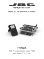 1
1
-
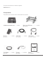 2
2
-
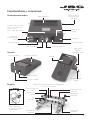 3
3
-
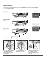 4
4
-
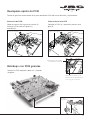 5
5
-
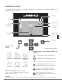 6
6
-
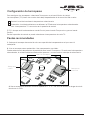 7
7
-
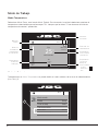 8
8
-
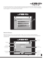 9
9
-
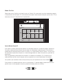 10
10
-
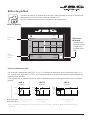 11
11
-
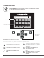 12
12
-
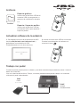 13
13
-
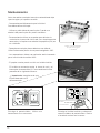 14
14
-
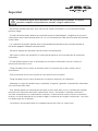 15
15
-
 16
16
-
 17
17
-
 18
18
-
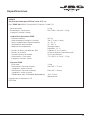 19
19
-
 20
20


jbc PHNEK Preheater Set El manual del propietario
- Tipo
- El manual del propietario
Artículos relacionados
Otros documentos
-
WIKA CTR3000 Instrucciones de operación
-
Miller MK130030G El manual del propietario
-
Miller PROHEAT 35 ce 907689, 907690 El manual del propietario
-
-
-
-
-