Kenmore Pro 233.56053 El manual del propietario
- Categoría
- Campanas de cocina
- Tipo
- El manual del propietario


KENMORE PRO LIMITED WARRANTY
WITH PROOF OF SALE, the following warranty coverage applies when this appliance
is correctly installed, operated and maintained according to all supplied instructions.
FOR ONE YEAR from the date of sale this appliance is warranted against defects in
material or workmanship. A defective appliance will receive free repair or replacement
at option of seller. This ONE YEAR coverage does not apply to the finish of any painted
or bright metal part.
FOR THIRTY DAYS from the date of sale, any painted or bright metal part of this
product will be replaced free of charge if its finish is defective in material or
workmanship.
For warranty coverage details to obtain free repair or replacement, visit the
web page: www.kenmore.com/warranty
All warranty coverage is void if this product is ever used for other than private
household purposes.
This warranty covers ONLY defects in material and workmanship, and will
NOT pay for:
1. Expendable items that can wear out from normal use, including but not limited to
filters, belts, bags or screw-in base light bulbs.
2. A service technician to clean or maintain this appliance, or to instruct the user in
correct appliance installation, operation and maintenance.
3. Service calls to correct appliance installation not performed by Sears authorized
service agents, or to repair problems with house fuses, circuit breakers, house
wiring, and plumbing or gas supply systems resulting from such installation.
4. Damage to or failure of this appliance resulting from installation not performed by
Sears authorized service agents, including installation that was not in accord with
electrical, gas or plumbing codes.
5. Damage to or failure of this appliance, including discoloration or surface rust, if it
is not correctly operated and maintained according to all supplied instructions.
6. Damage to or failure of this appliance, including discoloration or surface rust,
resulting from accident, alteration, abuse, misuse or use for other than its intended
purpose.
7. Damage to or failure of this appliance, including discoloration or surface rust,
caused by the use of detergents, cleaners, chemicals or utensils other than those
recommended in all instructions supplied with the product.
8. Damage to or failure of parts or systems resulting from unauthorized modifications
made to this appliance.
9. Service to an appliance if the model and serial plate is missing, altered, or cannot
easily be determined to have the appropriate certification logo.
Disclaimer of implied warranties; limitation of remedies
Customer’s sole and exclusive remedy under this limited warranty shall be product
repair or replacement as provided herein. Implied warranties, including warranties of
merchantability or fitness for a particular purpose, are limited to one year for the range
hood and thirty days for painted or bright metal parts, or the shortest period allowed by
law. Seller shall not be liable for incidental or consequential damages. Some states and
provinces do not allow the exclusion or limitation of incidental or consequential
damages, or limitation on the duration of implied warranties of merchantability or
fitness, so these exclusions or limitations may not apply to you.
This warranty applies only while this appliance is used in the United States.
This warranty gives you specific legal rights, and you may also have other rights
which vary from state to state.
Sears Brands Management Corporation, Hoffman Estates, IL 60179

READ AND SAVE THESE INSTRUCTIONS
WARNING
TO REDUCE THE RISK OF FIRE, ELECTRIC SHOCK, OR INJURY TO PERSONS,
OBSERVE THE FOLLOWING:
1. Use this unit only in the manner intended by the manufacturer. If you have questions,
contact the manufacturer at the address or telephone number listed in the warranty.
2. Before servicing or cleaning unit, switch power off at service panel and lock service
panel to prevent power from being switched on accidentally. When the service
disconnecting means cannot be locked, securely fasten a prominent warning device,
such as a tag, to the service panel.
3. Installation work and electrical wiring must be done by a qualified person(s) in accor-
dance with all applicable codes and standards, including fire-rated construction codes
and standards.
4. Sufficient air is needed for proper combustion and exhausting of gases through the flue
(chimney) of fuel burning equipment to prevent backdrafting. Follow the heating equip-
ment manufacturer’s guidelines and safety standards such as those published by the
National Fire Protection Association (NFPA), and the American Society for Heating,
Refrigeration and Air Conditioning Engineers (ASHRAE), and the local code authorities.
5. When cutting or drilling into wall or ceiling, do not damage electrical wiring and other
hidden utilities.
6. Ducted fans must always be vented to the outdoors.
7. Do not use this unit with any separate solid-state speed control device.
8. To reduce the risk of fire, use only metal ductwork.
9. This unit must be grounded.
TO REDUCE THE RISK OF A RANGE TOP GREASE FIRE:
A. Never leave surface units unattended at high settings. Boilovers cause smoking and
greasy spillovers that may ignite. Heat oils slowly on low or medium settings.
B. Always turn hood ON when cooking at high heat or when flambeing food (i.e. Crepes
Suzette, Cherries Jubilee, Peppercorn Beef Flambe’).
C. Clean ventilating fans frequently. Grease should not be allowed to accumulate on fan or
filter.
D. Use proper pan size. Always use cookware appropriate for the size of the surface
element.
WARNING
TO REDUCE THE RISK OF INJURY TO PERSONS IN THE EVENT OF A RANGE TOP
GREASE FIRE, OBSERVE THE FOLLOWING:*
1. SMOTHER FLAMES with a close-fitting lid, cookie sheet, or metal tray, then turn off the
burner. BE CAREFUL TO PREVENT BURNS. If the flames do not go out immediately,
EVACUATE AND CALL THE FIRE DEPARTMENT.
2. NEVER PICK UP A FLAMING PAN - You may be burned.
3. DO NOT USE WATER, including wet dishcloths or towels - violent steam explosion will
result.
4. Use an extinguisher ONLY if:
A. You know you have a Class ABC extinguisher and you already know how to operate
it.
B. The fire is small and contained in the area where it started.
C. The fire department is being called.
D. You can fight the fire with your back to an exit.
* Based on “Kitchen Fire Safety Tips” published by NFPA.
!
INTENDED FOR DOMESTIC COOKING ONLY
!

!
CAUTION
1. For indoor use only.
2. To reduce risk of fire and to properly exhaust air, be sure to duct air outside. Do not vent
exhaust air into spaces within walls or ceilings or into attics, crawl spaces, or garages.
3. Take care when using cleaning agents or detergents.
4. Avoid using food products that produce flames under the Range Hood.
5. For general ventilating use only. Do not use to exhaust hazardous or explosive materi-
als and vapors.
6. To avoid motor bearing damage and noisy and/or unbalanced impellers, keep drywall
spray, construction dust, etc. off power unit.
7. Your hood motor has a thermal overload which will automatically shut off the motor if it
becomes overheated. The motor will restart when it cools down. If the motor continues
to shut off and restart, have the hood serviced.
8. For best capture of cooking impurities, the bottom of the hood should be a minimum of
24" and a maximum of 30" above the cooking surface.
9. 3 installers are recommended because of the large size and weight of this hood.
10. This product is equipped with a thermostat which may start blower automatically. To
reduce the risk of injury and to prevent power from being switched on accidentally,
switch power off at service panel and lock or tag service panel.
11. Use with approved cord-connection kit only.
12. Please read specification label on product for further information and requirements.

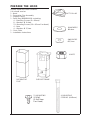
PREPARE THE HOOD
Unpack hood and check contents.
You should receive:
1 - Hood
1 - Decorative Flue Assembly
1 - Support Frame
1 - Parts Bag (B080810004) containing:
4 - Mounting Screws (6 x 60mm)
8 - Washers Ø 6.4mm
13 - Mounting Screws (3.9 x 9.5mm Pan Head)
4 - Nuts
4 - Washers Ø 5,2mm
1 - Duct Collar
1 - Installation Instructions
SUPPORT FRAME
DECORATIVE
FLUE
13 MOUNTING
SCREWS
(3.9x9.5mm
Pan Head)
8 WASHERS
Ø6.4mm
4 NUTS
4 MOUNTING
SCREWS (6x60mm)
DUCT COLLAR
4WASHERS
Ø5,2mm

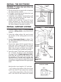
INSTALL THE DUCTWORK
WARNING: To reduce the risk of fire, use
only metal ductwork.
1. Decide where the ductwork will run between
the hood and the outside.
2. A straight, short duct run will allow the hood
to perform most efficiently.
3. Long duct runs, elbows, and transitions will
reduce the performance of the hood. Use
as few of them as possible.
4. Install a roof or wall cap. Connect 8" round
metal ductwork to cap and work back
towards hood location. Use duct tape to seal
the joints between ductwork sections.
INSTALL SUPPORT SYSTEM
1. At hood location, install 2 X 4 cross framing
between ceiling joists using dimensions
shown.
2. Finish the ceiling surface. Be sure to mark
the location of the ceiling joists and cross
framing.
3. Position the support frame as shown. The
UP ARROW should point towards the ceiling
after installation.
4. Secure the upper half of support frame to
joists and cross framing with four screws
(6x60mm and four washers (D.6.4mm).
Make sure screws are driven into center of
joists and framing for maximum strength.
5. Insert 4 screws (3.9x9.5mm) and 4 washers
(D. 5.2mm) located in the Hardware
Package into the height adjustment slots.
[Note that #4 screws and #4 washers can
be located on the front and on the rear
(opposite face)]. Loosen and re-tighten the
4 screws as necessary to adjust the overall
height of the support frame to the appropriate
level.
Note that the hood height is 10” and that:
- on 8’ ceilings, the bottom of the hood must
be 24” min. and 27” max. above the cooktop.
- on 9’ ceilings, the bottom of the hood must
be 27” min. and 30” max. above the cooktop.
TOP VIEW OF
SUPPORT FRAME
10
7
/8”
7
13
/16”
ROOF CAP
8” ROUND
ELBOW
24” TO 30” ABOVE
COOKING SURFACE
8” ROUND
DUCT
DECORATIVE
FLUE
CEILING
JOISTS
CROSS FRAMING
FRONT
HEIGHT
ADJUSTMENT
SLOTS
SUPPORT
FRAME
10
7
/8”
DRYWALL
MOUNTING
SCREWS
(6x60mm)
WASHERS
(Ø6.4mm)
HOOD

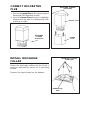
INSTALL DISCHARGE
COLLAR
Attach the discharge collar onto the hood; it
must be attached by means of 4 mounting
screws.
Remove the tape located on the damper.
MOUNTING SCREWS
(3.9x9.5mm)
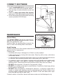
CONNECT DECORATIVE
FLUE
1. Secure the upper flue to the upper support
frame with the mounting screws.
2. Insert the lower flue moving it completely
towards the top and fix it temporarily with
retaining screws.
LOWER
FLUE
UPPER FLUE
MOUNTING SCREWS
(3.9x9.5mm)
INSERT THE LOWER FLUE
1
2
RETAINING
SCREWS
(3.9x9.5mm)
REMOVE THE
TAPE

WIRING
Note: This range hood must be properly
grounded. The unit should be installed by a
qualified electrician in accordance with all
applicable national and local electrical codes.
1. Remove the wiring box cover. Remove a
knockout from the wiring box.
2. Secure the conduit to the wiring box
through a conduit connector.
3. Make electrical connections. Connect white
to white, black to black and green to green.
4. Replace wiring box cover and screws. Make
sure that wires are not pinched between
cover and box.
WIRING BOX
COVER
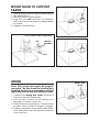
MOUNT HOOD TO SUPPORT
FRAME
1. Before mount hood to support frame remove
the electrical box.
2. Mount hood to support frame.
3. Use four (4) nuts and four (4) washers
(Ø6,4mm) to secure hood to support frame
as shown.
4. Replace electrical box.
BOLT
NUT
USE (4) NUTS AND (4) WASHERS
WASHER
(D.6.4MM)
ELECTRICAL BOX

MAINTENANCE
Grease Filters
The grease filters should be cleaned fre-
quently. Use a warm detergent solution. Grease
filters are dishwasher safe.
Remove filters by pushing filters towards the
back of hood and rotating filters downward.
Hood Cleaning
Stainless steel is one of the easiest materials to keep clean. Occasional care will help
preserve its fine appearance.
Cleaning tips:
• Hot water with soap or detergent is all that is usually needed.
• Follow all cleaning by rinsing with clear water. Wipe dry with a clean, soft cloth to
avoid water marks.
• For discolorations or deposits that persist, use a non-scratching household cleaner
or stainless steel polishing powder with a little water and a soft cloth.
• For stubborn cases, use a plastic scouring pad or soft bristle brush together with
cleaser and water. Rub lightly in direction of polishing lines or "grain" of the
stainless finish. Avoid using too much pressure which may mar the surface.
• DO NOT allow deposits to remain for long periods of time.
• DO NOT use ordinary steel wool or steel brushes. Small bits of steel may adhere
to the surface causing rust.
• DO NOT allow salt solutions, disinfectants, bleaches, or cleaning compounds to
remain in contact with stainless steel for extended periods. Many of these com-
pounds contain chemicals which may be harmful. Rinse with water after expo-
sure and wipe dry with a clean cloth.
Painted surfaces should be cleaned with warm water and mild detergent only.
GREASE FILTERS
8” ROUND
METAL
DUCT
LOWER
DECORATIVE
FLUE
SECTION
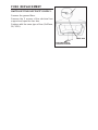
CONNECT DUCTWORK
1. Use 8" round metal duct to connect the duct
collar on the hood to the ductwork above.
2. Use duct tape to make all joints secure and
air tight.
3. Slide the lower decorative flue section
downward, until it fits properly around hood.
4. Secure decorative flue to hood with mounting
screws provided (3.9X9.5mm).
MOUNTING
SCREWS
(3.9X9.5mm)

LIGHT
SWITCH
PILOT
LAMP
BLOWER
SPEED
CONTROL
BLOWER
ON / OFF
SWITCH
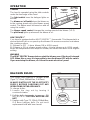
OPERATION
Controls
The hood is operated using the slide controls
under the front edge of the hood.
The light switch turns the halogen lights on
and off.
The blower on / off switch turns the blower on
to the running speed set by the blower speed
control. The blower must be turned on and off
using this switch.
The blower speed control changes the running speed of the blower (1-2-3).
The pilot lamp lights up whenever the blower is on.
HEAT SENTRY™
Your hood is equipped with a HEAT SENTRY™ thermostat. This thermostat is a
device that will turn on or speed up the blower if it senses excessive heat above
the cooking surface.
1) If blower is OFF - it turns blower ON to HIGH speed.
2) If blower is ON at a lower speed setting - it turns blower up to HIGH speed.
When the temperature level drops to normal, the blower will return to its original
setting.
WARNING
The HEAT SENTRY thermostat can start the blower even if the hood is turned
OFF. When this occurs, it is impossible to turn the blower OFF with its switch.
If you must stop the blower, do it from the main electrical panel.
HALOGEN BULBS
This range hood requires 4 halogen bulbs
(Type T3, 12Volt, 20Watt Max, G-4 Base).
ALWAYS SWITCH OFF THE ELECTRICITY
SUPPLY BEFORE CARRYING OUT ANY
OPERATIONS ON THE APPLIANCE.
To change bulbs:
1. Loosen the ring nut by turning it
counterclockwise.
2. Pull the bulb downwards to remove - DO
NOT ROTATE. CAUTION: BULB MAY BE
HOT!
3. Replace with Type T3, 12Volt, 20Watt Max,
G-4 Base halogen bulb. Do not touch
replacement bulb with bare hands!
RING
NUT

FUSE REPLACEMENT
SWITCH OFF THE ELECTRICITY SUPPLY.
Remove the grease filters.
Remove the 2 screws of the electrical box
support and open the fuse box.
Replace with the same type of fuse (5x20mm,
5A, 125V).
ELECTRICAL BOX
SUPPORT SCREWS
FUSE
FUSE BOX

GARANTÍA LIMITADA DE KENMORE PRO
La garantía siguiente se aplica, CON UN COMPROBANTE DE VENTA, cuando este aparato se
instala, se utiliza y se mantiene de acuerdo con todas las instrucciones dadas.
Este aparato está garantizado DURANTE UN AÑO, a partir de la fecha de venta, contra los
defectos de material y de mano de obra. Un aparato defectuoso será reparado o sustituido, según
decida el vendedor. El periodo de garantía de UN AÑO no se aplica al acabado de las piezas pinta-
das o de las piezas metálicas brillantes.
Durante un plazo de TREINTA DÍAS a partir de la fecha de compra, las piezas pintadas o metálicas
brillantes de este producto serán sustituidas sin gastos si su acabado tiene defectos de material o
de mano de obra.
Para mayor información sobre la forma de obtener una reparación o una sustitución gratuita,
sírvase consultar la página web www.kenmore.com/warranty
La garantía queda anulada si este producto se utiliza alguna vez con fines distintos al uso domésti-
co privado.
Esta garantía cubre ÚNICAMENTE los defectos de material y mano de obra y NO los sigui-
entes casos:
1. Artículos fungibles que pueden desgastarse con el uso normal, tales como filtros, correas,
bolsas o bombillas.
2. Gastos generados por un técnico de servicio para limpiar o dar mantenimiento a este aparato o
para dar instrucciones al usuario sobre la instalación, funcionamiento y mantenimiento correctos
del aparato.
3. Solicitudes de servicio para corregir una instalación del aparato no realizada por técnicos de
servicio autorizados de Sears o para reparar problemas de los fusibles, disyuntores y cableado
domésticos y de los sistemas de plomería o de alimentación de gas causados por dicha insta-
lación.
4. Daños en el aparato o fallos causados en él debidos a una instalación no realizada por técnicos
de servicio autorizados de Sears, incluyendo en ello los casos de instalación no conformes con
los códigos de electricidad, gas y plomería.
5. Daños en el aparato o fallos causados en él —entre ellos la descoloración o la oxidación
superficial— si no se usa correctamente o no se le da mantenimiento de acuerdo con todas las
instrucciones dadas.
6. Daños en el aparato o fallos causados en él —entre ellos la descoloración o la oxidación super-
ficial— debidos a un accidente, alteración, abuso, mal uso o uso distinto al previsto.
7. Daños en el aparato o fallos causados en él —entre ellos la descoloración o la oxidación super-
ficial— debidos al uso de detergentes, limpiadores, productos químicos o utensilios distintos a
los recomendados en todas las instrucciones dadas con el producto.
8. Daños en piezas o sistemas del aparato o fallos causados en ellos debidos a modificaciones no
autorizadas hechas en el aparato.
9. Gastos de servicio en un aparato cuya placa con el modelo y número de serie ha desaparecido,
ha sido alterada o no pueda comprobarse fácilmente que lleva el logo de certificación apropiado.
Denegación de garantías implícitas; limitación de los recursos
El único recurso de que dispone el cliente conforme a esta garantía limitada será la reparación
o la sustitución del producto, tal y como aquí se indica. Las garantías implícitas, tales como las
garantías de comerciabilidad o de idoneidad para un determinado propósito, se limitan a un año
para la campana de cocina y a treinta días para las piezas pintadas o metálicas brillantes, o al
periodo más corto que permita la ley. El vendedor no será responsable de los daños incidental-
es o derivados. Algunos estados y provincias no permiten que se excluyan o limiten los daños
incidentales o derivados o que se limite la duración de las garantías implícitas de comerciabilidad o
idoneidad; en tales casos, estas exclusiones o limitaciones no se aplican a usted.
Esta garantía sólo se aplica cuando el aparato se usa en Estados Unidos.
Esta garantía le otorga derechos jurídicos específicos, al margen de otros derechos que usted
pudiera tener y que varían de un estado a otro.
Sears Brands Management Corporation, Hoffman Estates, IL 60179

LEA Y CONSERVE ESTAS INSTRUCCIONES
ADVERTENCIA
PARA EVITAR EL RIESGO DE INCENDIO, CORTOCIRCUITO O DAÑO PARA LAS
PERSONAS, OBSERVE ATENTAMENTE LAS SIGUIENTES NORMAS:
1. Use esta unidad solamente de la manera indicada por el fabricante; si tiene dudas,
póngase en contacto con éste a la dirección o teléfono indicados en la garantía.
2. Antes de hacer una revisión o de limpiar la unidad, desconéctela de la red para evitar
que se encienda de manera accidental. En el caso de que éste no pueda ser desacti-
vado, se indicará nel panel de servicio.
3. El montaje y la instalación eléctrica debe hacerlos un técnico especializado siguiendo
las normas estándar e incluyendo aquellas de construcción anti incendio.
4. Necesita aire suficiente para una apropiada combustión y escape de gases a través del
tubo del depósito de quema de combustible. Para evitar que el humo aspirado vuelva a
la cocina, siga las directivas del fabricante y las normas estándar de siguridad así como
las normas publicadas por la Asociación de prevención de incendios (NFPA) y la Socie-
dad americana de especialistas en cale-facción, refrigeración y aire acondicionado y
además las normas de las autoridades locales.
5. Hacer un corte o un taladro en la pared o en el techo no debe dañar la instalación
eléctrica u otras instalaciones ocultas en la pared.
6. Los conductos ventiladores deben siempre desalojar al exterior.
7. No use esta unidad con dispositivo de control de la velocidad a estado sólido.
8. Para evitar el riesgo de incendio, use solamente conductos de metal.
9. Esta unidad tiene que ser conectada a tierra.
PARA EVITAR EL RIESGO DE FUEGO POR ALTO NIVEL DE GRASA:
A. Nunca abandone los quemadores con el fuego alto. La cocción causa humo y restos
de grasa que pueden arder. Caliente el aceite a fuego medio o bajo.
B. Encienda siempre la campana cuando cocine a fuego alto o cuando cocine alimentos
fácilmente inflamables. (por ejemplo Crepes Suzette, Cerezas Jubilee, Ternera
flambeada con granos de pimienta).
C. Limpie con frecuencia los ventiladores. No se debe acumular grasa en el ventilador o
en el filtro.
D. Usa el tamañp de cazuela apropiado. Use siempre utensilios de cocina de tamaño y
material adecuados.
ADVERTENCIA
PARA EVITAR EL RIESGO DE DAÑOS A PERSONAS EN CASO DE FUEGO POR ALTO
NÍVEL DE GRASA, TENGA EN CUENTA LO SIGUIENTE:*
1. SOFOQUE LA LLAMA con una tapadera apropiada, una bandeja metálica ó un utensilio
de cocína que pueda cubrirla, despues, apague el quemador. ACTÚE CON
PRECAUCÍON PARA EVITAR QUEMADURAS. Si la llama no se extingue inmedia-
tamente, SALGA Y LLAME A LOS BOMBEROS.
2. NUNCA COJA UNA SARTEN EN LLAMAS, porque corre el riesgo de quemarse.
3. NO USE AGUA ni paños o toallas húmidas porque puede provocarse una violenta
humareda.
4. Use un extintor SOLAMENTE si:
A. Posee un extintor de clase ABC y sabe perfectamente cómo usarlo.
B. El fuego es pequeño y está controlado en el mismo sitio en que empezó.
C. Ha llamado con anterioridad a los bomberos.
D. Puede combatir el fuego retrocedíendo hacia la salida.
* Basado en “Seguridad antifuego en la cocína” publicado por NFPA.
INDICADO PARA EL USO EN COCINAS DOMESTICAS
!
!

!
ADVERTENCIA
1. Para uso en interiores.
2. Para reducir el riesgo de incendios y para evacuar correctamente los humos, asegurarse
de haber realizado una conducción del aire hasta el exterior. No expulsar los humos en
espacios cerrados por paredes o techos, áticos, espacios angostos o garajes.
3. Prestar la máxima atención al utilizar productos de limpieza o detergentes.
4. Evitar el uso de productos alimentarios que puedan inflamarse bajo la campana.
5. Sólo para ventilación total. No use gases de escape peligrosos o materiales y vapores
explosivos.
6. Para evitar daños en el funcionamiento del motor e impulsores ruidosos y/o desequi-
librados, mantenga alejados de la unidad de encendido pulverizadores en seco o polvo.
7. El motor tiene un nivel de sobrecarga térmica que apaga automáticamente el motor
cuando se ha recalentado excesivamente. El motor se pone de nuevo en fincionamento
cuando la temperatura baja. Si el motor comienza a encenderse y a apagarse, deberá
hacer una revisión de éste.
8. Para limpiar mejor las impurezas al cocinar, la distancia entre la parte inferior de la
campana y la zona de cocción debe ser mínimo 24” - maximo 30”.
9. Debido a su gran tamaño y peso, se recomienda su montaje por parte de 3 técnicos
esperializados.
10. Este producto está dotado de un termostato que pone en marcha automáticamente el
motor. Para reducir el riesgo de daños y evitar que se encienda accidentalmente,
colocar el interruptor del panel de servicio en la posición OFF y bloquear el panel de
servizio o colocar una advertencia externa como por ejemplo un letrero o una chapita.
11.Use solamente con juego de conexión para alimentación aprobado.
12. Se recomienda leer la placa de caracteristicas del producto para ulterior información.

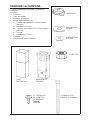
ARMAZÓN DE
SOPORTE
TUBO
DECORATIVO
13 TORNILLOS
DE MONTAJE
(3.9x9.5mm
cabeza
redonda
)
8 ARANDELAS
Ø6.4mm
4 TUERCAS
4 TORNILLOS DE
MONTAJE (6x60mm)
CASQUILLO
PREPARE LA CAMPANA
Sacar la campana de l’embalaje y controlar el
contenido.
Recivireis:
1 - Campana
1 - Tubo decorativo
1 - Armazón de soporte
1 - Bolsita (B080810004) con:
4 - Tornillos de montaje (6 x 60mm cabeza
redonda)
8 - Arandelas Ø 6.4mm
13 - Tornillos de montaje (3.9 x 9.5mm cabeza
redonda)
4 - Tuercas
4 - Arandelas Ø 5,2mm
1 - Casquillo
1 - Instrucciones para instalación
4 ARANDELAS
Ø5,2mm

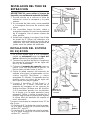
INSTALACION DEL TUBO DE
EXTRACCION
ADVERTENCIA: para evitar el riesgo de
incendio, use solamente material de metal.
1. Decida donde va a colocar el tubo de
extracción entre la campana y la parte
exterior.
2. Un recorrido de tubo corto y recto permitirá
a la campana funcionar de manera más
eficaz.
3. Los recorridos largos de tubo, codos y
manguitos impiden el buen funcionamiento
de la campana. Use el menor número de
ellos posible.
4. Instale una cubierta ó una tapa. Una el tubo
de metal de 8” (20cm) de diámetro a la
cubierta y retroceda hasta la posición de la
campana. Use une cinta para precintar las
juntas entre las partes del entubado.
CUBIERTA DEL TEJADO
TUBO DE 8” DE
DIÁMETRO
MANGUITO
DE 8” DE
DIÁMETRO RESPI-
RADERO
CAMPANA
TUBO
DECORATIVO
24” (61cm) A 30” (76cm)
POR ENCIMA DE LA
ZONA DE COCCIÓN
INSTALACION DEL SISTEMA
DE SUJECION
1. En el sitio donde vaya a ir la campana,
instale un entramado entre las vigas del
techo utilizando las medidas dadas.
2. Termine la superficie del techo. Asegúrese
de marcar la colocación de las vigas del
techo y del entramado.
3. Coloque el armazón de soporte como se
indica. Una vez efectuada la fijación, la
flecha debe señalar hacia el techo.
4. Sujete la mitad superior del armazón de
soporte a las vigas y al entramado con los
cuatro tornillos (6x60mm) y cuatro
arandelas (D. 6.4mm). Compruebe que los
tornillos vayan al centro de las vigas del
techo para una mayor rigidez.
5. Inserte 4 tornillos (3.9x9.5mm) y 4
arandelas (D. 5.2mm), ubicado en el
paquete de hardware en las ranuras de
ajuste de altura. [Nótese que # 4 tornillos
y # 4 arandelas pueden ser localizados
en el frente y en la parte posterior (cara
opuesta)]. Afloje y vuelva a apretar los 4
tornillos según sea necesario para ajustar
la altura total del bastidor de soporte al
nivel adecuado.
Tenga en cuenta que la campana tiene 10” de
alta y que:
- En techos de 8’, la distancia entre la campa-
na y la parte superior de la cocina debe ser
mínimo 24”, max 27”.
- En techos de 9’, la distancia entre la campa-
na y la parte superior de la cocina debe ser
mínimo 27”, max 30”.
7
13
/16”
(198mm)
VISTA SUPERIOR DEL ARMAZÓN
DE SOPORTE
10
7
/8” (276mm)
SUPERFICIE DEL
TECHO
TORNILLOS DE
MONTAJE
(6x60mm)
ARANDELAS
(Ø6.4mm)
PARTE
FRONTAL
ENTRAMADO
VIGAS
DEL
TECHO
ARMAZÓN DE
SOPORTE
RANURAS DE
AJUSTE DE LA
ALTURA
10
7
/8”

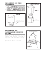
INSTALACION DEL
CASQUILLO DE UNION CON
EL TUBO
Sujete el casquillo de unión en la parte
superior de la campana; el casquillo se
asegura por medio de 4 tornillos de montaje.
Quitar la cinta adhesiva en la válvula.
TORNILLOS PARA EL
MONTAJE (3.9x9.5mm)
INSTALACION DEL TUBO
DECORATIVO
1. Sujete el tubo superior a la parte superior
de la estructura de soporte de madera en
la pared con los tornillos para el montaje.
2. Introduzca el tubo inferior hasta hacerlo
tocar el techo, y fíjelo momentáneamente
con los tornillos para el montaje.
TUBO
INFERIOR
TUBO
SUPERIOR
TORNILLOS PARA EL
MONTAJE (3.9x9.5mm)
INTRODUZCA EL TUBO
INFERIOR
1
2
TORNILLOS PARA EL
MONTAJE (3.9x9.5mm)
QUITAR LA
CINTA

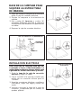
INSTALACION ELECTRICA
Nota: Este tipo de campana tiene que ser
conectada a tierra cuidadosamente. La
unidad debe instalarla un técnico electri-cista
siguiendo las normas nacionales y locales.
1. Quite la tapa de la caja de conexión
eléctrica y saque un cable.
2. Fije el “conduit” a la caja de conexión por
medio de un conector idóneo para el
“conduit”.
3. Haga las conexiones eléctricas, una blanco
con blanco, negro con negro y verde con
verde.
4. Vuelva a conectar la tapa de la caja de
conexión. Compruebe que los cables no
queden pillados.
TAPA DE CONEXIÓN
ELÉCTRICA
BASE DE LA CAMPANA PARA
SUJETAR LA ESTRUCTURA
DE MADERA
1. Antes de instalar la campana a la estructura
quitar la caja de conexión eléctrica.
2. Sujetar la campana a la estructura de
soporte.
3. Use cuatro (4) tuercas y cuatro (4)
arandelas (Ø6,4mm) para fijar la campana
a la estructura de madera en la pared como
se indica.
4. Reponer la caja de conexion electrica.
TUERCA
TORNILLO
CAJA DE CONEXIÓN ELÉCTRICA
USE (4) TUERCAS Y (4) ARANDELAS
ARANDELAS
(D.6.4MM)

MANTENIMIENTO
Filtros antigrasa
Los filtros antigrasa deben limpiarse a
menudo. Use un detergente que no sea fuerte.
Los filtros antigrasa se pueden meter en el
lavavajillas.
Extraiga los filtros tirando de ellos hacia atrás
de la campana y girándolos hacia abajo.
Limpieza de la campana
El acero inoxidable es uno de los meteriales más fáciles de limpiar, pero sería
aconsejable un especial cuidado en su uso para mantenerla en buen estado.
La campana se puede limpiar de las siguientes maneras:
• Agua caliente con jabón o detergente es la mejor manera para limpiarla.
• Aclárela con agua corriente, séquela con un paño suave y limpio para evitar las
huellas que deja el agua.
• Para las manchas o restos de grasa que persistan, use un producto químico
doméstico que no raye ó un limpiador para acero inoxidable con poca agua y un
paño suave.
• Si las manchas persisten, use un estropajo y un cepillo de cerdas suaves con un
producto limpiador y agua. Frote suavemente en el sentido del pulido o de las
“vetas” del remate del inoxidable. No apriete demasiado porque podría dañar la
superficie.
• No deje que las manchas se acumulen durante mucho tiempo.
• No use utensilios o cepillos de acero. Pequeñas particulas de acero pueden
adherirse y oxidarse.
• No use soluciones salinas, desinfectantes, lejías, o productos de limpieza que
permanezcan en contacto con el acero inoxidable durante largos periodos de
tiempo. Muchos de estos productos contienen componentes químicos que podrían
resultar nocivos. Aclare con agua y seque con un paño limpio.
Las superficies lacadas deben limpiarse solamente con agua tibia y detergente no
muy fuerte.
FILTROS ANTIGRASA
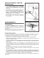
INSTALACION DEL TUBO DE
EXTRACCION
1. Use un tubo de metal de 8” de diámetro
para unir el casquillo situado en la parte
superior de la campana con el tubo de
extracción.
2. Use la cinta para unir todas las junturas, de
esta manera el tubo quedará hermético.
3. Deslice la parte inferior del tubo deco-
rativo hacia abajo hasta que ajuste
perfectamente con la campana.
4. Sujete el tubo decorativo a la campana con
los tornillos de montaje adjuntos
(3.9x9.5mm).
TUBO DE
METAL DE
8” DE
DIÁME-
TRO
PARTE
INFERIOR DEL
TUBO
DECORATIVO
TORNILLOS
DE MONTAJE
(3.9X9.5mm)

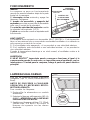
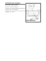
FUNCIONAMIENTO
Mandos
La campana se pone en funcionamiento
usando los mandos situados abajo de la parte
frontal de la campana.
El interruptor sa luz enciende y apaga las
lámparas halógenas.
El mando de encendido y apagado del
aspirador pone éste en posición de encendido
junto con el control de la velocidad.
El control de velocidad del aspirador cambia
la velocidad dal aspirador (1-2-3).
El piloto se enciende cuando el aspirador está
funcionando.
HEAT SENTRY
MR
Su campana esta equipada con termostato HEAT SENTRY
MR
. Este termostato
tiene un mecanismo que se encenderáo aceleratáel ventilador si se detecta un
calor excesivo encima de la cocina.
1) Si el ventilador esta apagando - el se prenderá a una velocidad máxima.
2) Si el ventilador esta encendido a una velocidad minima - el se prenderá a
una velocidad máxima.
Cuando la temperatura disminuye a un nivel normal, el ventilador vuelve a la
función de origen.
AVERTENCIA
El HEAT SENTRY
mr
termostato puede comenzar a funcionar al igual si la
campana esta parada. En este caso, es imposible parar el ventilador con los
interruptores. Si usted para la campana, halago a partir del panel eléctrico
principal.
CONTROL DE
LA VELOCIDAD
DEL ASPIRADOR
PILOTO
MANDO DE ENCENDIDO
Y APAGADO
DEL ASPIRADOR
INTERRUPTOR
DA LUZ
LAMPARAS HALOGENAS
Este tipo de campana necesita 4 lámparas
halógenas (Tipo T3, 12Volt, 20Watt Max, G-4
Base).
ANTES DE PROCEDER A CUALQUIER
OPERACIÓN, ES NECESARIO DESCO-
NECTAR EL APARATO.
Para cambiar las lámparas:
1. Destornillar la abrazadera en sentido
antihorario.
2. Extraiga la lámpara oblicuamente (NO LA
GIRE) - ATENCIÓN: LAS LÁMPARAS
PUEDEN ESTAR CALIENTES.
3. Sustituir con lámparas del tipo (T3, 12Volt,
20Watt Max, G-4 Base). No toque la
lámpara de repuesto con las manos
desnudas.
ABRAZADERA

CAJA DE
FUSIBLE
SUSTITUCION FUSIBLE
DESCONECTAR EL APARATO.
Remover los filtros antigrasa.
Remover los 2 tornillos de la placa instalación
eléctrica; abrir la caja fusible.
Sustituir por un fusible del mismo tipo
(5x20mm, 4A, 125V).
FUSIBLE
TORNILLOS DE LA PLACA
INSTALACIÓN ELÉCTRICA

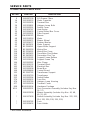
SERVICE PARTS
233.56053 SERIES RANGE HOOD
KEY NO. PART NO. DESCRIPTION
9 B08087138 N.3 Grease Filters
14 B02300233 Motor Capacitor
19 B03295005 Terminal Box
26 B02300891 Halogen Lamp Bulb
30 B03292291 Switch Cover
37 B02300787 Heat Sentry
39 B03294033 Control Board Box Cover
42 B03295001 Filter Support
45 BW0000072 Blower
48 B02310218 Motor
49 B03295071 Blower Wheel
53 B03204177 Rubber Washer
62 BE3402901 Motor Support
63 BE3346361 Upper Motor Support
115 BE3495228 Wiring Box
116 BE3334252 Wiring Box Cover
118 BE3403622 Decorative Flue Bottom
119 BE3403623 Decorative Flue Top
124 B03120185 Support Frame Bottom
125 B03120186 Support Frame Top
144 B03292287 Wire Clamp
147 BR2300135 Terminal Block
165 B03294781 Electrical Box
165 B03295008 Board Box
166 B08086668 Control Board
195 BE3345785 Transformer Support
208 B02300729 Transformer
223 B03292294 Switch Button
274 B03295035 Fuse Box
474 B02300789 Halogen Lamp Housing
477 B03295006 Terminal Cover
998 B080810004 Hardware Package
ARU B08092501 Duct Connector Assembly (Includes Key Nos.
56, 57)
* B06002008 Blower Assembly (Includes Key Nos. 45, 48,
49, 53, 42)
* B06107638 Switch Assembly (Includes Key Nos. 222, 223,
224, 225, 226, 228, 229, 230)
* B02300782 Fuse
* B02300674 Fuse Holder
* Not shown assembled.

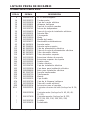
LISTA DE PIEZAS DE RECAMBIO
233.56053 SERIES RANGE HOOD
CÓD. N. PIEZA N. DESCRIPCIÓN
9 B08087138 N. 3 Filtros antigrasa
14 B02300233 Condensador
19 B03295005 Caja del cuadro eléctrico
26 B02300891 Lámpara halógena
30 B03292291 Tapa de la caja de mandos
37 B02300787 Sensor de temperatura
39 B03294033 Tapa de la caja de instalación eléctrica
42 B03295001 Soporte filtro
45 BW0000072 Convoyador
48 B02310218 Motor
49 B03295071 Manilla del motor
53 B03204177 Almohadilla antivibraziones
62 BE3402901 Soporte motor
63 BE3346361 Soporte motor superior
115 BE3495228 Caja de alimentación eléctrica
116 BE3334252 Tapa de la caja de alimentación eléctrica
118 BE3403622 Tubo decorativo inferior
119 BE3403623 Tubo decorativo superior
124 B03120185 Estructura inferior de soporte
125 B03120186 Estructura superior de soporte
144 B03292287 Sujeta cabos
147 BR2300135 Cuadro eléctrico
165 B03294781 Caja de instalación eléctrica
165 B03295008 Caja base para instalación eléctrica
166 B08086668 Base para instalación eléctrica
195 BE3345785 Soporte trasformador
208 B02300729 Trasformador
223 B03292294 Mando
274 B03295035 Caja fusible
474 B02300789 Caja de la lámpara halógena
477 B03295006 Tapa del cuadro eléctrico
998 B080810004 Accesorios para el montaje
ARU B08092501 Conjunto conector del tubo (Incluye los N. 56,
57)
* B06002008 Conjunto motor (Incluye los N. 45, 48, 49,
53, 42)
* B06107638 Conjunto mandos (Incluye los N. 222,
223, 224, 225, 226, 228, 229, 230)
* B02300782 Fusible
* B02300674 Portafusible
* Se encuentran por separado.

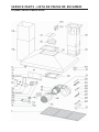
SERVICE PARTS - LISTA DE PIEZAS DE RECAMBIO
233.56053 SERIES RANGE HOOD


04308515
-
 1
1
-
 2
2
-
 3
3
-
 4
4
-
 5
5
-
 6
6
-
 7
7
-
 8
8
-
 9
9
-
 10
10
-
 11
11
-
 12
12
-
 13
13
-
 14
14
-
 15
15
-
 16
16
-
 17
17
-
 18
18
-
 19
19
-
 20
20
-
 21
21
-
 22
22
-
 23
23
-
 24
24
-
 25
25
-
 26
26
-
 27
27
-
 28
28


Kenmore Pro 233.56053 El manual del propietario
- Categoría
- Campanas de cocina
- Tipo
- El manual del propietario
en otros idiomas
- English: Kenmore Pro 233.56053 Owner's manual
Artículos relacionados
Otros documentos
-
NuTone Premier NP63000 Series Installation Instructions Manual
-
-
Best FEXTIS42PB Guía de instalación
-
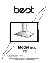 BEST Range Hoods IEX42 Manual de usuario
-
Best IS4270X100SS Manual de usuario
-
-
