Alamo Industrial Maverick Boom Mower Manual de usuario
- Categoría
- Cortadoras de césped
- Tipo
- Manual de usuario

© 2014 Alamo Group Inc.
Published 07/14 Part No. 02981992C
OPERATOR’S MANUAL
ALAMO INDUSTRIAL
®
1502 E. Walnut
Seguin, Texas 78155
830-372-3551
Email: [email protected]
BOOM MOWER
This Operator's Manual is an integral
part of the safe operation of this
machine and must be maintained with
the unit at all times. READ,
UNDERSTAND, and FOLLOW the
Safety and Operation Instructions
contained in this manual before
operating the equipment. C01-
Cover_AB
Important Operating and
Safety Instructions are
found in the Boom Mower
Safety Video that can be
instantly accessed on the
internet at: www.algqr.com/
abv
$0.00


In order to reduce accidents and enhance the safe operation of mowers, Alamo Industrial, in cooperation with other
industry manufacturers has developed the AEM/FEMA Industrial and Agricultural Mower Safety Practices video
and guide book.
The video will familiarize and instruct mower-tractor operators in safe practices when using industrial and
agricultural mowing equipment. It is important that Every Mower Operator
be educated in the operation of their
mowing equipment and be able to recognize the potential hazards that can occur while operating a mower. This
video, along with the mower operator’s manual and the warning messages on the mower, will significantly assist in
this important education.
Your Authorized Alamo Industrial Dealer may have shown this video and presented you a DVD Video when you
purchased your mower. If you or any mower operator have not seen this video, Watch the Video, Read this
Operator’s Manual, and Complete the Video Guidebook before operating your new mower. If you do not
understand any of the instructions included in the video or operator’s manual or if you have any questions
concerning safety of operation, contact your supervisor, dealer or Alamo Industrial.
If you would like a VHS video tape of the video, please email AEMVideo@alamo-group.com or Fax AEM VHS
Video at (830) 372-9529 or mail in a completed copy of the form on the back of this page to AEM VHS Video 1502
E Walnut Street, Seguin, TX 78155. and request the VHS video version. Please include your name, mailing
address, mower model and serial number.
Every operator should be trained for each price of equipment (Tractor and Mower), Understand the intended use,
and the potential hazards before operating the equipment.
The information and material listed above along with this Operator’s Manual can assist you in meeting the OSHA
requirement for Operator annual training.
OSHA TRAINING REQUIREMENTS
The following training requirements have been taken from Title 29, Code of Federal Regulations Part
1928.57 (a)(6). www.osha.gov
Operator Instructions. At the time of initial assignment and at least annually thereafter, the employer shall instruct
every employee who operates an agricultural tractor or implement in the safe operating practices and servicing of
equipment with which they are or will be involved, and of any other practices dictated by the work environment.

Alamo Industrial will provide
one (1) AEM Mower Safety Practices Video
Please Send Me: VHS Format – AEM/FEMA Mower Operator Safety Video
DVD Format – AEM/FEMA Mower Operator Safety Video
Mower Operator’s Manual
AEM Mower Operator’s Safety Manual
Requester Name:_________________________________Phone:___________________________
Requester
Address: ___________________________________________
City:_____________________________________
State: ____________________________________
Zip Code:_________________________________
Mower Model:___________________________Serial Number:_____________________________
Date Purchased:__________________________Dealer Salesperson:_________________________
Dealership Name:________________________ Dealership Location:________________________
Mail to:
AEM Video Services
1502 E. Walnut Street
Seguin, TX 78155
Or Fax to:
(830) 372-9529
Or Email to:

To the Owner/Operator/Dealer
This Operator's Manual is an integral part of the safe operation of this machine and must be maintained with the
implement at all times. A Manual canister is provided on the implement where this manual can be properly stored.
If you lose or damage this manual a free replacement manual can be obtained from an authorized Alamo Industrial
dealer or by down loading the manual from the Alamo Industrial website www.www.alamo-industrial.com
BEFORE YOU START! READ, UNDERSTAND, and FOLLOW the information provided in this manual, the AEM
Mower Safety manual and the tractor operator's manual carefully to learn how to operate and service your machine
properly. Failure to do so could result in personal injury to you and bystanders. All implements with moving parts
are potentially hazardous. Every effort has been made to ensure that the machine is safe but operators must avoid
engaging in unsafe practices and follow the written instructions provided. The manufacturer has designed this
implement to be used with all its safety equipment properly attached to minimize the chance of accidents.
SAFETY FIRST. Completely read and understand the safety section of this manual before operating this
equipment. Do not allow anyone to operate this equipment who has not fully read and understood this manual.
Contact your Dealer to explain any instructions that you do not fully understand.
The care you give your Alamo Industrial Implement will greatly determine your satisfaction with its performance and
its service life. Carefully read and follow the instructions in this manual to provide you with a thorough
understanding of your new implement and its intended use and service requirements.
All references made in this manual to right, left, front, rear, top or bottom are as viewed facing the direction of
forward travel with the implement properly attached to the tractor.
Replacement Parts information is located in a separate Parts Manual. Alamo Industrial mowers use balanced and
matched system components for blade carriers, blades, cuttershafts, knives, knife hangers, rollers, drivetrain
components, and bearings. These parts are made and tested to Alamo Industrial specifications. Non-genuine “will
fit” parts do not consistently meet these specifications. The use of “will fit” parts may reduce mower performance,
void warranties, and present a safety hazard. Use genuine Alamo Industrial mower parts for economy and safety.
For future reference, record your Alamo Industrial product model number and serial number.
Dealer Telephone Model Number
Owner Purchase Date Serial Number
SERIAL NUMBER PLATE

DEALER to CUSTOMER Pre-Delivery / Operation Instructions
Dealer should inform the Purchaser of this product of Warranty terms, provisions, and procedures that are
applicable. Dealer should also inform the Purchaser to review the contents of the Operator’s Manual including
safety equipment, safe operation and maintenance, to review the Safety Signs on the implement (and tractor if
possible) and of Purchaser’s responsibility to train his/her operators in safe operation procedures.
• IMPLEMENTS: I have explained that Deflectors, Chain Guards, or Solid Skirts must be installed and
maintained in good repair.
• DRIVELINES: I have made certain that all driveline, gearbox, and other shields are in good repair and fastened
securely in place to prevent injuries from entanglement or thrown objects.
• HYDRAULIC MACHINES: I have explained the necessity of using clean hydraulic oil, changing filters as
instructed, stopping leaks, damage caused by operating with over-heated oil, caring for hoses, using hoses of
proper rating, maintaining the specified operating pressure and the potential hazard of oil’s penetrating the
skin.
• FOLDING-TYPE IMPLEMENTS: I have explained that it is not possible to guard against thrown objects when
the head is lifted off ground and that operator is responsible to watch out for persons in the area. I have
explained that the lifted mower head or boom can contact overhead obstructions with damage to cables and
telephone lines and possible injury. I have explained that the extended head or boom or retracted boom can
contact power lines with resulting electrocution, injury or death and that operator is responsible for keeping
clear of such hazards.
PRE-DELIVERY SERVICE
CHECK AND ADJUST OR LUBRICATE AS REQUIRED
See Operator’s Manual for Details
Inspection Performed - Warranty and Safety Procedures Explained - Installation Complete
LUBRICATION & HYDRAULICS
Gearbox (Oil Levels)
Hydraulic Oil Level (External Tank)
Tractor Hydraulic Oil Level
Hydraulic Hoses (Not Kinked Tighten Connections)
Front Pump Drive (Assembly Is Tight And Shaft Properly
Aligned)
MOWER
Spindle And Motor Bolts Properly Torqued
Spindle Oil Level
Blade Carrier Bolts Properly Torqued/Retaining Pin In
Place
Mower Cutting Height And Level Adjusted
Cutting Shaft Bearings Lubricated
All Hardware Properly Torqued
Tire and Air Pressure/Lug Nuts (Correct Torque)
Wheel Bearings (Check, Grease, and Preload)
ATTACHMENTS & INSTALLATION
Deflectors Front And Rear
Shredding Attachments
Correct Blade Rotation Direction
Axle Arms And Beams
Tongue And Control Rods (Installed And Adjusted)
All Bolts - Pins And Nuts (Proper Torque)
MOWER TO TRACTOR CONNECTIONS
Draw Bar Length (Check And Set)
A-Frame Pivot & Links
Control Rods (Adjusted Equal)
Axle Height (Adjusted)
Cutting Height (Adjust)
Mount Kit-Pre-Operation Check Complete
Mower Wing (Adjust Level With The Center)
Mower Wing (Check For Proper Raising Operation)
C.V. Drivelines (Check Max Turn Radius)
Pull Type Hitch (Height Adjustment)
Mounting Hardware Properly Torqued
SAFETY ITEMS
Protective Shields (Operation And Installation)
Driveline Clutch (Torque Limiter) (Adjust And Run In)
Safety Decals (Installed)
Operator’s Manual (Supplied)
Tractor PTO Shield (Installed)
S.M.V. Emblem (Installed If Needed)
Tongue Jack (Installation and Operation)
Safety Tow Chain (Installed)
ADMA Driveline Safety Manual Supplied
AEM Mower Safety Manual (Supplied in Canister)
AEM Mower Safety Video has been shown to Purchaser

Table Of Contents
SAFETY SECTION .............................................................................................................. 1-1
GENERAL SAFETY INSTRUCTIONS AND PRACTICES ................................................................................. 1-2
Operator Safety .................................................................................................................................................. 1-3
CRUSHING HAZARDS ...................................................................................................................................... 1-4
CONNECTING OR DISCONNECTING IMPLEMENT SAFETY ........................................................................ 1-5
THROWN OBJECTS HAZARDS ....................................................................................................................... 1-6
RUN OVER HAZARDS ...................................................................................................................................... 1-8
PTO ENTANGLEMENT HAZARDS ................................................................................................................... 1-9
MOWER BLADE CONTACT HAZARDS ......................................................................................................... 1-10
HIGH PRESSURE OIL LEAK HAZARD .......................................................................................................... 1-11
ELECTRICAL & FIRE HAZARDS .................................................................................................................... 1-12
TRANSPORTING HAZARDS .......................................................................................................................... 1-13
HAZARDS WITH MAINTENANCE OF IMPLEMENT ...................................................................................... 1-14
PARTS INFORMATION ................................................................................................................................... 1-15
Decal Location ................................................................................................................................................. 1-15
Decal Description ............................................................................................................................................. 1-25
Federal Laws and Regulations ........................................................................................................................ 1-34
INTRODUCTION SECTION ................................................................................................. 2-1
Features ............................................................................................................................................................. 2-3
OPERATION SECTION ....................................................................................................... 3-1
OPERATOR REQUIREMENTS ......................................................................................................................... 3-3
TRACTOR REQUIREMENTS ............................................................................................................................ 3-4
ROPS and Seat Belt .......................................................................................................................................... 3-4
Operator Thrown Object Protection ................................................................................................................... 3-4
Tractor Lighting and SMV Emblem .................................................................................................................... 3-5
Tractor Ballast .................................................................................................................................................... 3-5
GETTING ON AND OFF THE TRACTOR ......................................................................................................... 3-6
Boarding the Tractor .......................................................................................................................................... 3-6
Dismounting the Tractor ..................................................................................................................................... 3-7
STARTING THE TRACTOR .............................................................................................................................. 3-7
CONNECTING ATTACHING HEADS TO THE BOOM ..................................................................................... 3-8
Connecting Mower Head Hydraulics .................................................................................................................. 3-8
PRE-OPERATION INSPECTION AND SERVICE ............................................................................................. 3-9
Tractor Pre-Operation Inspection/Service ........................................................................................................ 3-10
Boom Unit Pre-Operation Inspection and Service ........................................................................................... 3-11
Cutting Component Inspection ......................................................................................................................... 3-18
Blade Bolt Inspection ....................................................................................................................................... 3-19
JOYSTICK CONTROL SYSTEM SN MV24-1322 AND PREVIOUS & MV30-11278 TO PREVIOUS ............. 3-22
OPERATING THE BOOM JOYSTICK CONTROL .......................................................................................... 3-22
Maverick Boom Control System ....................................................................................................................... 3-23
The Hydraulic System ...................................................................................................................................... 3-23
The Mower Head Circuit .................................................................................................................................. 3-24
The Electronic Network .................................................................................................................................... 3-24
The Instrumentation ......................................................................................................................................... 3-26
Operator Interface ............................................................................................................................................ 3-28
Swing ............................................................................................................................................................... 3-30
Lift .................................................................................................................................................................... 3-31

Dipper .............................................................................................................................................................. 3-32
Telescoping Boom ........................................................................................................................................... 3-33
Tilt .................................................................................................................................................................... 3-34
Head Swivel ..................................................................................................................................................... 3-35
Door ................................................................................................................................................................ 3-36
JOYSTICK CONTROL SYSTEM SN MV24-1323 TO CURRENT & SN MV30-11279 TO CURRENT ........... 3-37
OPERATING THE BOOM JOYSTICK CONTROL .......................................................................................... 3-37
Mower Head Power ......................................................................................................................................... 3-38
Swing ............................................................................................................................................................... 3-39
Lift .................................................................................................................................................................... 3-40
Dipper .............................................................................................................................................................. 3-41
Tilt .................................................................................................................................................................... 3-42
Door ................................................................................................................................................................ 3-43
Telescoping Boom ........................................................................................................................................... 3-44
Head Swivel ..................................................................................................................................................... 3-45
DRIVING THE TRACTOR AND IMPLEMENT ................................................................................................. 3-46
Starting the Tractor .......................................................................................................................................... 3-47
Brake and Differential Lock Setting .................................................................................................................. 3-48
Driving the Tractor and Boom .......................................................................................................................... 3-49
OPERATING UNIT SN MV24-1322 AND PREVIOUS & MV30-11278 TO PREVIOUS .................................. 3-50
OPERATING THE BOOM UNIT AND ATTACHED HEAD .............................................................................. 3-50
Foreign Debris Hazards/Overhead Obstructions ............................................................................................. 3-51
Operating Speed and Ground Speed .............................................................................................................. 3-52
Operating the Attached Mower Heads ............................................................................................................. 3-52
Shutting Down the Attached Head ................................................................................................................... 3-56
TRACTOR, BOOM, AND ATTACHED HEAD STORAGE ............................................................................... 3-57
OPERATING UNIT SN MV24-1323 TO CURRENT & SN MV30-11279 TO CURRENT ................................. 3-58
OPERATING THE BOOM UNIT AND ATTACHED HEAD .............................................................................. 3-58
Foreign Debris Hazards/Overhead Obstructions ............................................................................................. 3-59
Operating Speed and Ground Speed .............................................................................................................. 3-60
Operating the Attached Mower Heads ............................................................................................................. 3-60
Operational Instruction ..................................................................................................................................... 3-61
Shutting Down the Attached Head ................................................................................................................... 3-66
Shutting Down the Attached Head - For (Optional Equipment) ....................................................................... 3-67
TRANSPORTING THE TRACTOR AND IMPLEMENT ................................................................................... 3-68
Transporting on Public Roadways ................................................................................................................... 3-69
Hauling the Tractor and Implement .................................................................................................................. 3-71
TROUBLESHOOTING GUIDE ........................................................................................................................ 3-73
MAINTENANCE SECTION .................................................................................................. 4-1
HAZARDS WITH MAINTENANCE OF IMPLEMENT ........................................................................................ 4-2
PARTS INFORMATION ..................................................................................................................................... 4-3
LUBRICATION INFORMATION ......................................................................................................................... 4-3
HYDRAULIC FLUID ........................................................................................................................................... 4-5
Proper Oil Level ................................................................................................................................................. 4-6
Blades ................................................................................................................................................................ 4-7
Hardware ........................................................................................................................................................... 4-8
Cylinder Rod Maintenance ................................................................................................................................. 4-8
Boom Cylinder Removal and Replacement Instructions .................................................................................... 4-9
Hydraulic Component Maintenance Schedule ................................................................................................. 4-10
LEXAN Sheet Cleaning Recommendations ..................................................................................................... 4-10
Cleaning Procedure for Small Areas - Manual ................................................................................................. 4-10
Cleaning Procedure for Large Areas - Automated ........................................................................................... 4-11
Other Important Instructions for All Lexan Sheets: .......................................................................................... 4-11
Additional Important Considerations for Multiwall, Corrugated and Sign Sheet: ............................................. 4-11

Graffiti removal from Lexan* Margard* sheet ................................................................................................... 4-11
PROPER TORQUE FOR FASTENERS .......................................................................................................... 4-11
SERVICE OF SPINDLE HOUSING ................................................................................................................. 4-13
ROLLER BEARING REPLACEMENT ............................................................................................................. 4-15
Timber Cat Head .............................................................................................................................................. 4-16
Buzzbar Head .................................................................................................................................................. 4-17
Flail Axe Head .................................................................................................................................................. 4-19
Flail Blades Inspection ..................................................................................................................................... 4-20
Blade Pins and D-Ring Inspection ................................................................................................................... 4-21
Flail Axe Blades Inspection .............................................................................................................................. 4-22
Flail Axe Blade Bolt Inspection ........................................................................................................................ 4-23
Grass Flail Head .............................................................................................................................................. 4-24
General Information on Flail Mower Vibration .................................................................................................. 4-26
START UP PROCEDURE ............................................................................................................................... 4-27


Safety Section 1-1
© 2014 Alamo Group Inc.
SAFETY SECTION

SAFETY
MAVERICK 07/14 Safety Section 1-2
© 2014 Alamo Group Inc.
SAFETY
GENERAL SAFETY INSTRUCTIONS AND PRACTICES
A careful operator is the best operator. Safety is of primary importance to the manufacturer and should be to
the owner/operator. Most accidents can be avoided by being aware of your equipment, your surroundings,
and observing certain precautions. The first section of this manual includes a list of Safety Messages that, if
followed, will help protect the operator and bystanders from injury or death. Read and understand these
Safety Messages before assembling, operating or servicing this Implement. This equipment should only be
operated by those persons who have read the manual, who are responsible and trained, and who know how
to do so responsibly.
The Safety Alert Symbol combined with a Signal Word, as seen below, is used throughout this
manual and on decals which are attached to the equipment. The Safety Alert Symbol means:
“ATTENTION! BECOME ALERT! YOUR SAFETY IS INVOLVED!” The Symbol and Signal Word
are intended to warn the owner/operator of impending hazards and the degree of possible injury
faced when operating this equipment.
Indicates an imminently hazardous situation that, if not avoided, WILL result in DEATH OR
VERY SERIOUS INJURY.
Indicates an imminently hazardous situation that, if not avoided, COULD result in DEATH
OR SERIOUS INJURY.
Indicates an imminently hazardous situation that, if not avoided, MAY result in MINOR
INJURY.
Identifies special instructions or procedures that, if not strictly observed, could result in
damage to, or destruction of the machine, attachments or the environment.
NOTE: Identifies points of particular interest for more efficient and convenient operation or repair.
READ, UNDERSTAND, and FOLLOW the following Safety Messages. Serious injury or
death may occur unless care is taken to follow the warnings and instructions stated in this
Manual and in the Safety Messages on the implement. Always follow the instruction in this
manual and use good common sense to avoid hazards.
NOTE: If you want a translation of this safety section in one of the following Languages, please contact:
Translations at 1502 E. Walnut Street Seguin, TX 78155; Fax: (830) 372-9529; Safety Section Translations
are available in Spanish, Portuguese, French, German, Russian.
PN GS01
Practice all usual and customary safe working precautions and above all---
remember safety is up to YOU
. Only YOU can prevent serious injury or death
from unsafe practices.

SAFETY
MAVERICK 07/14 Safety Section 1-3
© 2014 Alamo Group Inc.
SAFETY
Operator Safety
TO AVOID SERIOUS INJURY OR DEATH DO THE FOLLOWING:
• READ, UNDERSTAND and FOLLOW Operator's Manual instructions, Warnings and Safety Messages.
• WEAR SAFETY GLASSES, safety shoes, hard hat, hearing protection and gloves when operating or repairing equipment
• WEAR appropriate breathing respirator when operating in dusty conditions to avoid respiratory diseases.
• DO NOT WEAR loose clothing or jewelry to avoid rotating parts entanglement injury.
• DO NOT USE DRUGS or ALCOHOL before or while operating equipment.
• DO NOT ALLOW anyone to operate equipment under the influence of drug or alcohol.
• CONSULT medical professional for medication impairment side effects.
• STAY CLEAR of hot surfaces such as Mufflers, hydraulic pumps, valves and tanks.
• STAY ALERT, prolonged operation can cause fatigue, STOP and REST.
GENERAL OPERATING SAFETY
VISIBILITY CONDITIONS WHEN MOWING:
• OPERATE IN DAYLIGHT or with lights that gives at least 100 yards clear visibility.
• BE ABLE TO SEE and identify passersby, steep slopes, ditches, drop-offs, overhead obstructions, power lines, debris and foreign
objects.
• Avoid backing up while mowing, vision may be limited, severe damage or injury can occur.
• DO NOT run tractor in enclosed building without adequate exhaust ventilation.
GROUND SPEED WHEN MOWING:
• NORMAL SPEED range is between 1 to 2 mph(1-3 kph).
• ADJUST MOWING SPEED for terrain conditions and grass type, density and cut height.
• REDUCE MOWING SPEED when near steep slopes, ditches, drop-offs, overhead obstructions, power lines and to avoid debris
and foreign objects.
TRACTOR and MOWER
• DO NOT operate the tractor or mower unless the equipment is maintained and operating properly.
• DISCONTINUE OPERATION if tractor or mower electrical and hydraulic controls do no function properly.
• DISCONTINUE OPERATION of the tractor if the braking or steering systems do not function properly.
• DO NOT operate the tractor or mower if there are any hydraulic leaks.
INSECT INFESTATION
• DO NOT operate in areas where bees or insects may attack unless you WEAR PROTECTIVE CLOTHING or use enclosed tractor
cab.
PTO SPEED:
• DO NOT EXCEED IMPLEMENT RATED PTO SPEED
• AVOID exceeding rated PTO speeds that may result in broken drivelines or blade failures.
SAFETY SIGNS:
• REPLACE missing, damaged or unreadable safety signs immediately.
PN OSBM-01

SAFETY
MAVERICK 07/14 Safety Section 1-4
© 2014 Alamo Group Inc.
SAFETY
CRUSHING HAZARDS
TO AVOID SERIOUS INJURY OR DEATH FROM FALLING OFF TRACTOR, EQUIPMENT RUN OVER,
ROLLOVER AND CRUSHING BY FALLING WING OR IMPLEMENT:
• USE ROPS and SEAT BELT equipped tractors for mowing operations.
• KEEP ROPS lock in up position.
• ALWAYS BUCKLE UP seat belt when operating tractor and equipment.
• ONLY OPERATE tractor and equipment while seated in tractor seat.
WHEN RAISING BOOM MOWER:
•Raise or lower ONLY WHILE SEATED in tractor seat with seat belt buckled.
• KEEP BYSTANDERS CLEAR of area TO AVOID crushing.
• KEEP sufficient clearance around implement and wings TO AVOID contacting buildings or overhead power lines.
LIFTED Equipment can fall from mechanical or hydraulic failure or inadvertent Control Lever movement.
TO AVOID EQUIPMENT FALLING while working near or under lifted boom, components and
Mower Head:
• SECURELY SUPPORT or block up raised equipment, wings and components.
• BLOCK UP and securely support equipment before putting hands, feet or body under raised equipment or lifted compo-
nents.
• KEEP BYSTANDERS CLEAR of raised boom or mower head until securely blocked up.
WHEN PARKING Implement and Tractor:
• LOWER Mower Head to the ground or BLOCK lifted parts before leaving equipment.
• NEVER leave implement unattended in a raised position.
TO AVOID CHILDREN FALLING OFF OR BEING CRUSHED BY EQUIPMENT:
• NEVER ALLOW children to play on or around Tractor or Implement.
• DO NOT operate without operator CAB or OVERHEAD protection. Falling limbs and debris can cause injuries.
PN CHBM-01

SAFETY
MAVERICK 07/14 Safety Section 1-5
© 2014 Alamo Group Inc.
SAFETY
CONNECTING OR DISCONNECTING IMPLEMENT SAFETY
TO AVOID SERIOUS INJURY OR DEATH FROM BEING CRUSHED BY TRACTOR OR
IMPLEMENT:
WHEN connecting mower head to the boom
:
• KEEP BYSTANDERS AWAY from tractor and mower.
• Ensure there is enough room to lift and swing the boom with out hitting objects
BEFORE
connecting and disconnecting the mower head or boom:
• STOP TRACTOR ENGINE, place transmission into park, engage parking brake and remove key.
WHEN connecting and disconnecting the mower head or boom:
• DO NOT crawl or walk under raised mower head or boom. (Refer to Instructions in Operation Section)
WHEN CONNECTING IMPLEMENT DRIVELINE:(If equipped)
TO AVOID
implement driveline coming loose during operation:
• LUBRICATE yoke spring locking collar to ensure it freely slides on PTO shaft.
• SECURELY seat yoke locking balls in PTO shaft groove.
• PUSH and PULL DRIVELINE on both the tractor and implement PTO SHAFTS to ensure it is SECURELY
ATTACHED.
TO AVOID
broken driveline during operations:
• CHECK driveline for proper length between PTO shaft and implement gearbox shaft.(Refer to Instructions in Operation
Section)
• Drivelines too short can pull apart or disengage.
• Drivelines too long can bottom out.
• Bottoming driveline telescoping assembly will stop sliding and become solid.
• Driveline bottoming can push through support bearings and break off PTO shaft.
CONTACT DEALER
if implement driveline does not match Tractor PTO shaft:
• DO NOT USE PTO ADAPTER.
Using a PTO adapter can cause:
• Excessive vibration, thrown objects, blade and implement failures by doubling operating speed.
• Increased working length exposing unshielded driveline areas and entanglement hazards.
PN CDBM-01

SAFETY
MAVERICK 07/14 Safety Section 1-6
© 2014 Alamo Group Inc.
SAFETY
THROWN OBJECTS HAZARDS
ROTARY MOWERS CAN THROW OBJECTS 300 FEET OR MORE UNDER ADVERSE
CONDITIONS.
TO AVOID SERIOUS INJURY OR DEATH TO OPERATOR OR BYSTANDERS FROM THROWN OBJECTS:
• KEEP bystanders 300 feet away
STOP MOWING IF PASSERSBY ARE WITHIN 300 FEET UNLESS:
• All THROWN OBJECT SHIELDING including, Front and Rear Deflectors, Chains Guards, Steel Guards, Bands,
Side Skirts and Skid Shoes in place and in good condition when mowing.
• Mower is close and parallel to ground without exposing blades.
• MOWING AREA has been inspected and foreign materials and debris have been removed.
• DO NOT shred or mow loose or previously cut material if BYSTANDERS are within 300 feet.
• PASSERSBY are inside enclosed vehicle.
INSPECT AREA FOR POTENTIAL THROWN OBJECTS BEFORE MOWING:
• REMOVE debris, rocks, wire, cable, metal objects and other foreign material from area.
Wire, cable, rope, chains and metal objects can be thrown or swing outside deck with great velocity:
1. MARK objects that cannot removed.
2. AVOID these objects when mowing.
HIGH GRASS and WEED AREA INSPECTION:
• INSPECT for and REMOVE any hidden large debris.
• MOW at Intermediate height
• INSPECT and remove remaining debris
• MOW at final height.
MOWER THROWN OBJECT SHIELDING:
• KEEP all thrown object shielding including, Front and Rear Deflectors, Chains Guards, Steel Guards, Bands, Side
Skirts and Skid Shoes in place and in good condition when mowing.
• DO NOT OPERATE with any thrown object shielding missing, damaged or removed.
RIGHT OF WAY (Highway) MOWING
• Stop mowing if any bystander comes within 300 feet of the mower.
• No shielding is 100% effective in preventing thrown objects. To Reduce Possibility of Injury:
1. MAINTAIN MOWER SHIELDING, side skirts, skid shoes, and blades in good operational condition,
2. RAISE CUTTING HEIGHT to 6 INCHES minimum,
3. INSPECT AREA thoroughly before mowing to REMOVE potential THROWN OBJECT HAZARDS,
4. NEVER ALLOW BLADES to CONTACT SOLID OBJECTS like wire, rocks, post, curbs, guardrails, or ground
while mowing.
PN TOBM-01

SAFETY
MAVERICK 07/14 Safety Section 1-7
© 2014 Alamo Group Inc.
SAFETY
THROWN OBJECTS HAZARDS (Continued)
MOWER OPERATION:
• DO NOT exceed mower's rated Cutting Capacity or cut non-vegetative material.
• USE ENCLOSED TRACTOR CABS when two or more mowers are operating in mowing area.
• Do Not mow in areas where bees or insects may attack unless you WEAR PROTECTIVE CLOTHING or
use enclosed tractor cab.
• ADJUST mower head close and parallel to ground without exposing blades.
• ADJUST cutting HEIGHT to AVOID BLADE CONTACT with solid objects like wire, rocks, posts, curbs,
guard rails and fixed obstructions.
• CLOSE Mower door and stop operating if bystanders come within 300 feet of the mower.
• Keep mower door closed when cutting close to the ground.
• Open door only to cut large brush or tree limbs. Close door immediately after cutting limb.
• DO NOT push mower head down onto material to cut it, use the front tips of the mower blades to cut into
the material.
• DO NOT operate mower when mower is in transport position.
• STOP MOWING immediately if blades strike heavy objects, fixed structures, metal guard rails and
concrete structures:
1. BLADES CAN FAIL from impact and objects can be thrown with great velocity.
2. INSPECT and REPLACE any damaged blades.
3. CHECK blade carrier and REPLACE if damaged.
• DO NOT mow in standing water TO AVOID possible BLADE FAILURE.
• AVOID MOWING in reverse:
1. STOP PTO and back up mower.
2. LOWER mower, engage PTO and mow forward.
• DISENGAGE mower head and wait until BLADES stop rotating before raising mower to transport
position.
• DO NOT ENGAGE PTO with mower in transport position.
• STOP mowing when EXCESSIVE VIBRATION occurs:
1. STOP PTO and tractor ENGINE.
2. INSPECT mower for vibration source.
3. REPLACE any damage parts and bent or damaged BLADES.
PN TOBM-02

SAFETY
MAVERICK 07/14 Safety Section 1-8
© 2014 Alamo Group Inc.
SAFETY
RUN OVER HAZARDS
TO AVOID SERIOUS INJURY OR DEATH FROM FALLING OFF TRACTOR OR
EQUIPMENT RUN OVER:
• USE ROPS and SEAT BELT equipped tractors for mowing operations.
• KEEP ROPS locked in UP position.
• ONLY start tractor while seated in tractor seat.
• ALWAYS BUCKLE UP seat belt when operating tractor and equipment.
• ONLY OPERATE tractor and equipment while seated in tractor seat.
• NEVER ALLOW RIDERS on tractor or implement.
• When not mowing stow Boom and Mower head in transport location before moving.
WHEN MOUNTING AND DISMOUNTING TRACTOR:
• ONLY mount or dismount when tractor and moving parts are stopped.
• STOP ENGINE AND PTO, engage parking brake, lower implement, allow all moving parts to stop and
remove key before dismounting from tractor.
PN ROBM-01

SAFETY
MAVERICK 07/14 Safety Section 1-9
© 2014 Alamo Group Inc.
SAFETY
PTO ENTANGLEMENT HAZARDS
KEEP AWAY FROM ROTATING DRIVELINES AND ELEMENTS TO AVOID SERIOUS INJURY OR
DEATH:
STAY AWAY
and KEEP hands, feet and body AWAY from rotating blades, drivelines and parts until all moving
elements have stopped.
• STOP, LOOK and LISTEN before approaching the mower to make sure all rotating motion has stopped.
• ROTATING COMPONENTS CONTINUE to ROTATE after the PTO is shut off.
PTO SHIELDING:
TO AVOID SERIOUS INJURY OR DEATH FROM ENTANGLEMENT WHEN OPERATING IMPLEMENT:
• KEEP PTO shields, integral driveline shields and input shields installed
• DO NOT OPERATE mower without shields and guards in place or missing
• REPAIR OR REPLACE if damage, broken or missing
• ALWAYS REPLACE GUARDS that have been removed for service or maintenance.
• Do Not use PTO or PTO guard as a step.
TO AVOID
broken driveline during operations:
• CHECK driveline for proper length between PTO shaft and implement gearbox shaft.(Refer to Instructions in
Operation Section)
• Drivelines too short can pull apart or disengage.
• Drivelines too long can bottom out.
Bottoming driveline telescoping assembly will stop sliding and become solid.
• Driveline bottoming can push through support bearings and break off PTO shaft
• AVOID sharp turns or lift mower to heights to cause driveline "knocking".
• Lubricate driveshaft-telescoping components weekly.
CONTACT DEALER
if implement driveline does not match Tractor PTO shaft:
• DO NOT USE PTO ADAPTER.
Using a PTO adapter can cause excessive vibration, thrown objects, blade and implement failures by
doubling operating speed. Increased working length exposing unshielded driveline areas. PN PE01

SAFETY
MAVERICK 07/14 Safety Section 1-10
© 2014 Alamo Group Inc.
SAFETY
MOWER BLADE CONTACT HAZARDS
KEEP AWAY FROM ROTATING BLADES TO AVOID SERIOUS INJURY OR DEATH FROM
BLADE CONTACT:
• STAY AWAY and KEEP HANDS, FEET and BODY AWAY from rotating blades, drivelines and parts until all moving
elements have stopped.
• DO NOT put hands or feet under mower decks
• STOP rotating BLADES disengage mower switch and PTO and wait for blade to stop rotating before raising mower
head.
• DO NOT approach Sickle Bar head until Tracto Engine has been shut off.
• STOP LOOK and LISTEN before approaching the mower to make sure all rotating motion has stopped.
PN MBBM-01

SAFETY
MAVERICK 07/14 Safety Section 1-11
© 2014 Alamo Group Inc.
SAFETY
HIGH PRESSURE OIL LEAK HAZARD
TO AVOID SERIOUS INJURY OR DEATH FROM HIGH PRESSURE HYDRAULIC OIL LEAKS
PENERATING SKIN:
• DO NOT OPERATE equipment with oil or fuel leaks.
• KEEP all hydraulic hoses, lines and connections in GOOD CONDITION and TIGHT before applying system
pressure.
• RELIEVE HYDRAULIC PRESSURE before disconnecting lines or working on the system.
• REMOVE and replace hose if you suspect it leaks. Have dealer test it for leaks.
HIGH PRESSURE FLUID LEAKS CAN BE INVISIBLE.
WHEN CHECKING FOR HYDRAULIC LEAKS AND WORKING AROUND HYDRAULIC SYSTEMS:
• ALWAYS WEAR safety glasses and impenetrable gloves.
• USE paper or cardboard to search for leaks.
• DO NOT USE hands or body parts to search for leak.
• KEEP hands and body AWAY from pin holes and nozzles ejecting hydraulic fluid.
• Hydraulic fluid may cause gangrene if not surgically removed immediately by a doctor familiar with this form of injury.
Use caution when removing Hydraulic Tank cap.
• Tank contents maybe under pressure
• Allow oil to cool before removing cap.
• Relieve oil pressure before removing cap slowly.
• Stay away from hot oil that may spray from tank.
PN HPBM-01

SAFETY
MAVERICK 07/14 Safety Section 1-12
© 2014 Alamo Group Inc.
SAFETY
ELECTRICAL & FIRE HAZARDS
TO AVOID SERIOUS INJURY OR DEATH FROM ELECTRICAL CONTACT WHEN
WORKING AROUND ELECTRICAL POWER LINES, GAS LINES AND UTILITY LINES:
• INSPECT mowing area for overhead or underground electrical power lines, obstructions, gas lines,
cables and Utility, Municipal, or other type structure.
• KEEP all raised wings at a 10 feet or greater distance from all power lines and overhead obstructions.
• DO NOT allow mower to contact with any Utility, Municipal, or type of structures and obstructions.
• CALL 811 and 1-800-258-0808 for identify buried utility lines.
FIRE PREVENTION GUIDELINES while Operating, Servicing, and Repairing Mower and Tractor to
reduce equipment and grass fire Risk:
• EQUIP Tractor with a FIRE EXTINGUISHER
• DO NOT OPERATE mower on a tractor equipped with under frame exhaust
• DO NOT SMOKE or have open flame near Mower or Tractor
• DO NOT DRIVE into burning debris or freshly burnt area
• AVOID FIRE IGNITION by not allowing mower blade to contact solid objects like metal or rock.
• DO NOT operate if oil is leaking. Repair oil leak and remove all accumulated oil before operating.
• CLEAR any grass clippings or debris buildup around mower hydraulic pumps, valves or tanks.
• SHUT OFF ENGINE while refueling.
PN EFBM-01

SAFETY
MAVERICK 07/14 Safety Section 1-13
© 2014 Alamo Group Inc.
SAFETY
TRANSPORTING HAZARDS
TO AVOID SERIOUS INJURY AND DEATH WHEN TOWING OR TRANSPORTING EQUIPMENT:
• KEEP transport speed BELOW 20 mph to maintain control of equipment.
• REDUCE SPEED on inclines, on turns and in poor towing conditions.
• DO NOT TOW with trucks or other vehicles.
• USE only properly sized and equipped tractor for towing equipment.
• FOLLOW all local traffic regulations.
TRACTOR REQUIREMENTS FOR TOWING OR TRANSPORTING IMPLEMENTS:
• ONLY TRANSPORT with tractor with ROPS in the raised position.
• USE properly sized and equipped tractor that exceeds implement weight by at least 20%.
• KEEP 20% of tractor weight on front wheels to maintain safe steering.
BEFORE TRANSPORTING OR TOWING IMPLEMENT:
TRACTOR INSPECTION:
• CHECK steering and braking for proper operation and in good condition.
• CHECK SMV sign, reflectors and warning lights for proper operation and visibility behind unit.
• CHECK that your driving vision is not impaired by tractor, cab, or implement while seated in tractor seat.
• ADJUST your operating position, mirrors, and implement transport for clear vision for traveling and traffic conditions.
PREPARE IMPLEMENT FOR TRANSPORTING OR TOWING:
• Store Boom and Mower in transport positions and engage transport locks if equipped.
DETERMINE STOPPING CHARACTERISTICS OF TRACTOR AND IMPLEMENT FOR TRANSPORTING OR
TOWING:
BRAKING TESTS:
• Stopping distance with implement attached may increase
• Observe STOPPING distances increases with increased speeds.
• DETERMINE the maximum safe transport speed that does not exceed 20 mph.
• Reduce travel speed in wet or icy roads, stopping distances increase.
DETERMINE MAXIMUM TURING SPEED BEFORE OPERATING ON ROADS OR UNEVEN GROUND:
• TEST equipment in slowly increasing speed in turns to determine it can be operated at higher speeds.
• USE REDUCED turning speeds in sharp turns to avoid equipment turning over.
WHEN TOWING OR TRANSPORTING EQUIPMENT:
• Always WEAR SEAT BELT when operating or transporting mower.
• USE low speeds to avoid overturn with raised wings.
• USE low speeds and gradual steering on curves, hills, rough or uneven surfaces and on wet roads.
• TURN ON tractor FLASHING WARNING LIGHTS.
• ALLOW clearance for implement swing while turning.
KEEP raised boom mower 10 feet or greater distance from all power lines and overhead obstructions.
PN THBM-01

SAFETY
MAVERICK 07/14 Safety Section 1-14
© 2014 Alamo Group Inc.
SAFETY
HAZARDS WITH MAINTENANCE OF IMPLEMENT
AVOID SERIOUS INJURY OR DEATH FROM COMPONENT FAILURE BY KEEPING IMPLEMENT IN
GOOD OPERATING CONDITION IN PERFORMING PROPER SERVICE, REPAIRS AND
MAINTENANCE.
BEFORE PERFORMING SERVICE, REPAIRS AND MAINTENANCE ON THE IMPLEMENT:
• STOP ENGINE AND PTO, engage parking brake, lower implement, allow all moving parts to stop and remove key before
dismounting from tractor.
•
PLACE implement on ground or securely block up raised equipment. Use large blocks on soft or wet soil.
•
PUSH and PULL Remote Hydraulic Cylinder lever to relieve hydraulic pressure.
•
DISCONNECT Pump solenoid valve or PTO driveline connection before servicing mower head.
•
WEAR SAFETY GLASSES, PROTECTIVE GLOVES and follow SAFETY PROCEDURES when performing service, repairs
and maintenance on the implement:
•Always
WEAR protective GLOVES when handling blades, knives, cutting edges or worn component with sharp edges.
•Always
WEAR GLOVES and SAFETY GLASSES when servicing hot components
•
AVOID CONTACT with hot hydraulic oil tanks, pumps, motors, valves and hose connection surfaces.
•
SECURELY support or BLOCK UP raised implement, framework and lifted components before working underneath equipment.
•
FOLLOW INSTRUCTIONS in maintenance section when replacing hydraulic cylinders to prevent component falling.
•
STOP any implement movements and SHUT-OFF TRACTOR engine before doing any work procedures.
•
USE ladder or raised stands to reach high equipment areas inaccessible from ground.
•
ENSURE good footing by standing on solid flat surfaces when getting on implement to perform work.
•
FOLLOW manufacturer's instructions in handling oils, solvents, cleansers, and other chemical agents.
•
DO NOT change any factory-set hydraulic calibrations to avoid component or equipment failures.
•
DO NOT modify or alter implement, functions or components.
•
DO NOT WELD or repair rotating mower components. These may cause vibrations and component failures being thrown from
mower.
PERFORM SERVICE, REPAIRS, LUBRICATION AND MAINTENANCE OUTLINED IN IMPLEMENT MAINTENANCE
SECTION:
• INSPECT for loose fasteners, worn or broken parts, leaky or loose fittings, missing or broken cotter keys and washers on pins, and
all moving parts for wear.
•
REPLACE any worn or broken parts with authorized service parts.
• Inspect mower blade spindle to ensure bearing preload. If loose repair before operating.
•
LUBRICATE unit as specified by lubrication schedule
•
NEVER lubricate, adjust or remove material while it is running or in motion.
•
TORQUE all bolts and nuts as specified.
BLADE INSPECTION:
• Inspect blade carrier and blades daily.
• Check blade and blade carrier BOLT TORQUE daily. Loose bolts can cause blade or blade bolt failures.
• REPLACE, bent, damage, cracked and broken blades immediately with new blades.
•
AVOID blade failures and thrown broken blades. DO NOT straighten, weld, or weld hard-facing blades.
SAFETY SHIELDS, GUARDS AND SAFETY DEVICES INSPECTION:
• KEEP all Deflectors, Chain Guards, Steel Guards, Gearbox Shields, and PTO integral shields, Bands, Side Skirts and Skid Shoes
in place and in good condition.
•
REPLACE any missing, broken or worn safety shields, guards and safety devices.
• Engine Exhaust, some of its constituents, and certain vehicle components contain or emit chemicals known to the state of California
to cause cancer, birth defects or other reproductive harm.
• Battery posts, terminals and related accessories contain lead and lead compounds, chemicals known to the state of California to
cause cancer, birth defects or other reproductive harm.
PN HMBM-01

SAFETY
MAVERICK 07/14 Safety Section 1-15
© 2014 Alamo Group Inc.
SAFETY
PARTS INFORMATION
Decal Location
NOTE: Alamo Industrial supplies safety decals on this product to promote safe operation. Damage to the
decals may occur while in shipping, use, or reconditioning. Alamo Industrial cares about the safety of its
customers, operators, and bystanders, and will replace the safety decals on this product in the field, free of
charge (Some shipping and handling charges may apply). Contact your Alamo Industrial dealer to order
replacement decals.
PARTS INFORMATION
Alamo Industrial mowers use balanced and matched system components for blade carriers, blades,
cuttershafts, knives, knife hangers, rollers, drivetrain components, and bearings. These parts are made and
tested to Alamo Industrial specifications. Non-genuine "will fit" parts do not consistently meet these
specifications. The use of “will fit” parts may reduce mower performance, void mower warranties, and present
a safety hazard. Use genuine Alamo Industrial mower parts for economy and safety.
(SPAM-1)
SEE YOUR ALAMO DEALER

SAFETY
MAVERICK 07/14 Safety Section 1-16
© 2014 Alamo Group Inc.
SAFETY
TRACTOR / TANK / PUMP / TURRET / COUNTERWEIGHT / CANISTER

SAFETY
MAVERICK 07/14 Safety Section 1-17
© 2014 Alamo Group Inc.
SAFETY
ITEM PART NO. QTY. TYPE DESCRIPTION
1. 03200347 1 REFLECT SMV
2. D677 1 INSTRUCT Boom Mower Safety Booklet
3. D617 2 DANGER Hydraulic Oil Hazard
4. D625 1 WARNING Pressurized Tank
5. D627 1 IMPORTANT Avoid Electrical Damage
6. 02982828 1 ATTENTION Correct Hydraulic Fluid
7. 02971943 2 LOGO Alamo Industrial
8. 02983409 1 INSTRUCT Hose Connection
9. D644 1 INSTRUCT Blue Dot Decal
10. D645 1 INSTRUCT Red Dot Decal
11. D726 1 INSTRUCT Grease Fitting Inside
12. D835 1 DANGER Multi-Hazard
13. D624 1 IMPORTANT Operate at 540 RPM
14. D659 1 INSTRUCT Lube Chart
15. 1458392 1 REFLECT Red Reflector
16. 1458393 1 REFLECT Yellow Reflector
17. 002508 1 LOGO Alamo Industrial
18. 00776031 1 -------------- Canister
19. 02981992C 1 -------------- Operator’s Manual

SAFETY
MAVERICK 07/14 Safety Section 1-18
© 2014 Alamo Group Inc.
SAFETY
ROTARY HEAD
ITEM PART NO. QTY. LEVEL DESCRIPTION
1. 00757139 3 LOGO Alamo Industrial Logo
2. D626 2 WARNING Thrown Object Hazard
3. D619 1 WARNING Blade Rotation
4. 2738332 1 REFLECT Red Reflector
5. 2738333 1 REFLECT Yellow Reflector
6. 02988384 NFS SERIAL NUM Serial Number Plate
7. 02970889 1 LOGO 60” Rotary
8. D622 1 DANGER Blades, Thrown Objects
9. D620 1 WARNING Replace Blades in Pairs
10. D564 1 WARNING Use Genuine Parts
11. D718 1 INSTRUCT Lube Chart
12. D621 1 IMPORTANT Lube Spindle Every 40 hrs
13. D637 1 WARNING Disconnect Hydraulic Solenoid
14. 00757140 1 LOGO Alamo Industrial Logo

SAFETY
MAVERICK 07/14 Safety Section 1-19
© 2014 Alamo Group Inc.
SAFETY
FLAIL AXE
ITEM PART NO. QTY. LEVEL DESCRIPTION
1. D661 1 INSTRUCT Lube Chart
2. D564 1 DANGER Thrown Objects
3. D622 1 DANGER Thrown Objects Safety Shields
4. D637 1 WARNING Disconnect Hydraulic Solenoid
5. D646 1 WARNING Shield and Guards (Under Guard)
6. D641 1 WARNING Belt Shield
7. 000108 1 INSTRUCT Flail Operation
8. 000678 1 INSTRUCT Grease Fitting Inside
9. 00757139 2 LOGO Alamo Industrial
10. NFS 1 SERIAL NUM Flail Axe Serial Number
11. 02979551 1 LOGO Alamo Industrial Logo
12. 02970887 1 LOGO Flail Axe 48”

SAFETY
MAVERICK 07/14 Safety Section 1-20
© 2014 Alamo Group Inc.
SAFETY
GRASS FLAIL
ITEM PART NO. QTY. TYPE DESCRIPTION
1. D564 1 WARNING Use Genuine Parts
2. D637 1 WARNING Disconnect Hydraulic Solenoid
3. D641 1 WARNING Belt Shield
4. D646 1 WARNING Shields & Guards
5. D626 1 DANGER Thrown Object Hazard
6. D661 1 INSTRUCT Lubrication Chart
7. 00757139 1 LOGO Alamo Industrial Logo
8. 000108 1 INSTRUCT Flail Operation Instructions
9. nfs 1 SERIAL PLATE Flail Head Serial Plate
10. 000678 1 INSTRUCT Grease Fitting
11. 1458392 1 REFLECT Red Reflector
12. 1458393 1 REFLECT Yellow Reflector

SAFETY
MAVERICK 07/14 Safety Section 1-21
© 2014 Alamo Group Inc.
SAFETY
BUZZBAR
ITEM PART NO. QTY. TYPE DESCRIPTION
1. D660 1 INSTRUCT Lubrication Location
2. D646 2 DANGER Guard Missing
3. D619 1 WARNING Blade Rotation
4. D564 1 WARNING Use Genuine Parts
5. D638 1 WARNING Hearing Loss
6. D641 1 WARNING Belt Shield
7. D637 1 WARNING Disconnect Hydraulic Solenoid
8. D640 1 DANGER Amputation Hazard
9. 1458392 1 REFLECT Red Reflector
10. 1458393 1 REFLECT Yellow Reflector
11. 02975516 1 INTRUCT No Hitch Post Here
12. 00757139 2 LOGO Alamo Industrial
13. nfs 1 SERIAL NUM Serial Plate
14. 02974998 1 LOGO Logo Buzzbar
15. 02979546 1 LOGO Alamo Industrial

SAFETY
MAVERICK 07/14 Safety Section 1-22
© 2014 Alamo Group Inc.
SAFETY
TIMBERCAT
ITEM PART NO. QTY. TYPE DESCRIPTION
1. D546 1 DANGER Guard Missing
2. D637 1 WARNING Disconnect Hydraulic Solenoid
3. D564 1 WARNING Genuine Parts
4. D639 1 DANGER Amputation Hazard
5. D662 1 INSTRUCT Lubrication Decal
6. 00757139 1 LOGO Alamo Industrial Logo
7. 00757140 1 LOGO Alamo Industrial Logo
8. 02971931 1 LOGO Timber Cat

SAFETY
MAVERICK 07/14 Safety Section 1-23
© 2014 Alamo Group Inc.
SAFETY
DITCHER
ITEM PART NO. QTY. TYPE DESCRIPTION
1. D564 1 WARNING Use Genuine Parts
2. D642 1 WARNING Thrown Objects
3. D637 1 WARNING Disconnect Hydraulic Solenoid
4. D663 1 INSTRUCT Lubrication Chart
5. NFS 1 SERIAL PLATE Ditcher Serial Number Plate
6. 999204 1 LOGO Ditcher Decal
7. 002508 1 LOGO Alamo Industrial Logo
8. 02970888 1 LOGO Boom Ditcher Name Logo

SAFETY
MAVERICK 07/14 Safety Section 1-24
© 2014 Alamo Group Inc.
SAFETY
BOOM ARM
ITEM PART NO. QTY. TYPE DESCRIPTION
1. D623 6 WARNING Pinch Points
2. 02988484 2 NAME Logo, 18’ Axtreme
3. 02988485 2 NAME Logo, 22’ Axtreme
4. 02988486 2 NAME Logo, 25’ Axtreme
5. 02981987 1 INSTRUCT Hydraulic Connection
6. NFS 1 SER PLT Serial Number Plate

SAFETY
MAVERICK 07/14 Safety Section 1-25
© 2014 Alamo Group Inc.
SAFETY
Decal Description

SAFETY
MAVERICK 07/14 Safety Section 1-26
© 2014 Alamo Group Inc.
SAFETY

SAFETY
MAVERICK 07/14 Safety Section 1-27
© 2014 Alamo Group Inc.
SAFETY

SAFETY
MAVERICK 07/14 Safety Section 1-28
© 2014 Alamo Group Inc.
SAFETY

SAFETY
MAVERICK 07/14 Safety Section 1-29
© 2014 Alamo Group Inc.
SAFETY

SAFETY
MAVERICK 07/14 Safety Section 1-30
© 2014 Alamo Group Inc.
SAFETY

SAFETY
MAVERICK 07/14 Safety Section 1-31
© 2014 Alamo Group Inc.
SAFETY

SAFETY
MAVERICK 07/14 Safety Section 1-32
© 2014 Alamo Group Inc.
SAFETY

SAFETY
MAVERICK 07/14 Safety Section 1-33
© 2014 Alamo Group Inc.
SAFETY

SAFETY
MAVERICK 07/14 Safety Section 1-34
© 2014 Alamo Group Inc.
SAFETY
Federal Laws and Regulations
This section is intended to explain in broad terms the concept and effect of federal laws and regulations concerning
employer and employee equipment operators. This section is not intended as a legal interpretation of the law and
should not be considered as such.
Employer-Employee Operator Regulations
U.S. Public Law 91-596 (The Williams-Steiger Occupational and Health Act of 1970) OSHA
This Act Seeks:
“...to assure so far as possible every working man and woman in the nation safe and healthful working
conditions and to preserve our human resources...”
DUTIES
Sec. 5 (a) Each employer-
(1) shall furnish to each of his employees employment and a place of employment which are free from
recognized hazards that are causing or are likely to cause death or serious physical harm to his employees;
(2) shall comply with occupational safety and health standards promulgated under this Act.
(b) Each employee shall comply with occupational safety and health standards and all rules, regulations and
orders issued pursuant to this Act which are applicable to his own actions and conduct.
OSHA Training Requirements
Title 29, Code of Federal Regulations Part 1928.57(a)(6). www.osha.gov
Operator instructions. At the time of initial assignment and at least annually thereafter, the employer shall
instruct every employee who operates an agricultural tractor and implements in the safe operating practices
and servicing of equipment with which they are or will be involved, and of any other practices dictated by the
work environment.
Keep all guards in place when the machine is in operation;
Permit no riders on equipment
Stop engine, disconnect the power source, and wait for all machine movement to stop before servicing,
adjusting, cleaning or unclogging the equipment, except where the machine must be running to be properly
serviced or maintained, in which case the employer shall instruct employees as to all steps and procedures
which are necessary to safely service or maintain the equipment.
Make sure everyone is clear of machinery before starting the engine, engaging power, or operating the
machine.
Employer Responsibilities:
To ensure employee safety during Tractor and Implement operation, it is the employer’s responsibility to:
1. Train the employee in the proper and safe operation of the Tractor and Implement.
2. Require that the employee read and fully understand the Tractor and Implement Operator’s manual.
3. Permit only qualified and properly trained employees to operate the Tractor and Implement.
4. Maintain the Tractor and Implement in a safe operational condition and maintain all shields and guards on the
equipment.
5. Ensure the Tractor is equipped with a functional ROPS and seat belt and require that the employee operator
securely fasten the safety belt and operate with the ROPS in the raised position at all times.
6. Forbid the employee operator to carry additional riders on the Tractor or Implement.
7. Provide the required tools to maintain the Tractor and Implement in a good safe working condition and provide the
necessary support devices to secure the equipment safely while performing repairs and service.
8. Require that the employee operator stop operation if bystanders or passersby come within 300 feet.
Child Labor Under 16 Years of Age
Some regulations specify that no one under the age of 16 may operate power machinery. It is your responsibility to
know what these regulations are in your own area or situation. (Refer to U.S. Dept. of Labor, Employment Standard
Administration, Wage & Home Division, Child Labor Bulletin #102.)

Introduction Section 2-1
© 2014 Alamo Group Inc.
INTRODUCTION SECTION

INTRODUCTION
MAVERICK 07/14 Introduction Section 2-2
© 2014 Alamo Group Inc.
INTRODUCTION
We are pleased to have you as a Alamo Industrial customer. Your Boom Mower has been carefully designed
with care and built with quality materials by skilled workers to give maximum service with minimum down time.
This manual is provided to give you the necessary operating and maintenance instructions for keeping your
rotary cutter in top operating condition. Careful use and timely service saves extensive repairs and costly
downtime losses. Please read this manual thoroughly. Understand what each control is for and how to use it.
The Assembly Section instructs the owner/operator in the correct assembly of the Mower using standard and
optional equipment. The Parts Listing section is designed to familiarize the owner/operator with replaceable
parts on the Mower. This section provides exploded assembly drawings of each mower component illustrating
each piece and the corresponding part number.
Safety is of primary importance to the owner/operator and to the manufacturer. The first section of this manual
includes a list of Safety Messages, that, if followed, will help protect the operator and bystanders from injury or
death. Many of the Safety Messages will be repeated throughout the manual. The owner/operator/dealer
should know these Safety Messages before assembly and be aware of the hazards of operating this mower
during assembly, use, and maintenance. The Safety Alert Symbol combined with a Signal Word, as seen
below, is intended to warn the owner/operator of impending hazards and the degree of possible injury faced
when operating this machine.
Indicates an imminently hazardous situation that, if not avoided, WILL result in DEATH OR
VERY SERIOUS INJURY.
Indicates an imminently hazardous situation that, if not avoided, COULD result in DEATH
OR SERIOUS INJURY.
Indicates an imminently hazardous situation that, if not avoided, MAY result in MINOR
INJURY.
Identifies special instructions or procedures that, if not strictly observed, could result in
damage to, or destruction of the machine, attachments or the environment.
NOTE: Identifies points of particular interest for more efficient and convenient operation or repair.

INTRODUCTION
MAVERICK 07/14 Introduction Section 2-3
© 2014 Alamo Group Inc.
INTRODUCTION
Your Maverick Boom is designed for heavy-duty cutting in limited access areas such as
highway, park, and rural roadsides, overhead growth, ditches, levees, and other such
grass and limb control uses in generally hard-to-reach areas. Your Maverick Boom can be
equipped with a variety of cutting heads designed for specific cutting needs.
Features
Available Boom Lengths – 21’ to 24’ and 27’ to 30’
Exclusive Design – Boom features a 180° front to back hydraulic swing utilizing a turret-
style mechanism fastened to a slewing ring bearing.
Ease of Transport – Two-piece boom rest is mounted to the tractor to cradle the boom securely when in
transport position.
Operator Safety – Polycarbonate window protection is standard equipment.
Hydraulic System – Self contained hydraulic circuit for both mowing head and boom control, front-mounted
hydraulic reservoir for improved visibility, safety and operator access.
Minimum Tractor Requirement – 90 engine HP, 90” wheelbase, 8500 LB shipping weight for the 21’ to 24’
reach; 90 engine HP, 100° wheelbase, 9500 LB shipping weight for the 27’ to 30’ reach.
Warranty – One year parts and labor. Non-governmental users subject to a modified policy. Only genuine
Alamo Industrial OEM parts may be used for warranty replacement.
Cutting Head Options
Optional Equipment
Severe Duty Rotary Cable control system
Flail-Axe® Brush Cutter Front axle stabilizer (4WD only)
Heavy Duty Grass Flail Quick Hitch® attachment system
BuzzBar® Special paint
Ditcher®
Timber Cat®
DIRECTION
Throughout this Manual front and rear, left and right are determined by the normal direction of travel, the same
as driving an automobile.

INTRODUCTION
MAVERICK 07/14 Introduction Section 2-4
© 2014 Alamo Group Inc.
INTRODUCTION
Attention Owner/Operator
BEFORE OPERATING THIS MACHINE:
1. Carefully read the Operator’s Manual, completely understand the Safety Messages and instructions, and
know how to operate correctly both the tractor and implement.
2. Fill out the Warranty Card in full. Be sure to answer all questions, including the Serial Number of the
implement. Mail within 30 days of delivery date of this implement.
NOTE: Warranties are honored only if completed “Owner Registration and Warranty” forms are received by
Alamo Industrial within thirty days of delivery of the implement.
3. Record the Model and Serial Numbers on the Warranty page at the front of the Operator’s Manual. Keep this
as part of the permanent maintenance file for the implement.

INTRODUCTION
MAVERICK 07/14 Introduction Section 2-5
© 2014 Alamo Group Inc.
INTRODUCTION
ALAMO-INDUSTRIAL
LIMITED WARRANTY
1. LIMITED WARRANTIES
1.01. Alamo Industrial warrants for one year from the purchase date to the original non-commercial, governmental, or municipal purchaser
(“Purchaser”) and warrants for six months to the original commercial or industrial purchaser (“Purchaser”) that the goods purchased
are free from defects in material or workmanship.
1.02. Manufacturer will replace for the Purchaser any part or parts found, upon examination at one of its factories, to be defective under
normal use and service due to defects in material or workmanship.
1.03. This limited warranty does not apply to any part of the goods which has been subjected to improper or abnormal use, negligence,
alteration, modification, or accident, damaged due to lack of maintenance or use of wrong fuel, oil, or lubricants, or which has served
its normal life. This limited warranty does not apply to any part of any internal combustion engine, or expendable items such as
blades, shields, guards, or pneumatic tires except as specifically found in your Operator’s Manual.
1.04. Except as provided herein, no employee, agent, Dealer, or other person is authorized to give any warranties of any nature on behalf of
Manufacturer.
2. REMEDIES AND PROCEDURES.
2.01. This limited warranty is not effective unless the Purchaser returns the Registration and Warranty Form to Manufacturer within 30 days
of purchase.
2.02. Purchaser claims must be made in writing to the Authorized Dealer (“Dealer”) from whom Purchaser purchased the goods or an
approved Authorized Dealer (“Dealer”) within 30 days after Purchaser learns of the facts on which the claim is based.
2.03. Purchaser is responsible for returning the goods in question to the Dealer.
2.04. If after examining the goods and/or parts in question, Manufacturer finds them to be defective under normal use and service due to
defects in material or workmanship, Manufacturer will:
(a)Repair or replace the defective goods or part(s) or
(b)Reimburse Purchaser for the cost of the part(s) and reasonable labor charges (as determined by Manufacturer) if
Purchaser paid for the repair and/or replacement prior to the final determination of applicability of the warranty by
Manufacturer.
The choice of remedy shall belong to Manufacturer.
2.05. Purchaser is responsible for any labor charges exceeding a reasonable amount as determined by Manufacturer and for returning the
goods to the Dealer, whether or not the claim is approved. Purchaser is responsible for the transportation cost for the goods or part(s)
from the Purchaser to the Dealer.
3. LIMITATION OF LIABILITY.
3.01. MANUFACTURER DISCLAIMS ANY EXPRESS (EXCEPT AS SET FORTH HEREIN) AND IMPLIED WARRANTIES WITH
RESPECT TO THE GOODS INCLUDING, BUT NOT LIMITED TO, MERCHANTABILITY AND FITNESS FOR A PARTICULAR
PURPOSE.
3.02. MANUFACTURER MAKES NO WARRANTY AS TO THE DESIGN, CAPABILITY, CAPACITY, OR SUITABILITY FOR USE OF THE
GOODS.
3.03. EXCEPT AS PROVIDED HEREIN, MANUFACTURER SHALL HAVE NO LIABILITY OR RESPONSIBILITY TO PURCHASER OR
ANY OTHER PERSON OR ENTITY WITH RESPECT TO ANY LIABILITY, LOSS, OR DAMAGE CAUSED OR ALLEGED TO BE
CAUSED DIRECTLY OR INDIRECTLY BY THE GOODS INCLUDING, BUT NOT LIMITED TO, ANY INDIRECT, SPECIAL,
CONSEQUENTIAL, OR INCIDENTAL DAMAGES RESULTING FROM THE USE OR OPERATION OF THE GOODS OR ANY
BREACH OF THIS WARRANTY. NOT WITHSTANDING THE ABOVE LIMITATIONS AND WARRANTIES, MANUFACTURER’S
LIABILITY HEREUNDER FOR DAMAGES INCURRED BY PURCHASER OR OTHERS SHALL NOT EXCEED THE PRICE OF THE
GOODS.
3.04. NO ACTION ARISING OUT OF ANY CLAIMED BREACH OF THIS WARRANTY OR TRANSACTIONS UNDER THIS WARRANTY
MAY BE BROUGHT MORE THAN TWO (2) YEARS AFTER THE CAUSE OF ACTION HAS OCCURRED.
4. MISCELLANEOUS.
4.01. Proper Venue for any lawsuits arising from or related to this limited warranty shall be only in Guadalupe County, Texas.
4.02. Manufacturer may waive compliance with any of the terms of this limited warranty, but no waiver of any terms shall be deemed to be a
waiver of any other term.
4.03. If any provision of this limited warranty shall violate any applicable law and is held to be unenforceable, then the invalidity of such
provision shall not invalidate any other provisions herein.
4.04. Applicable law may provide rights and benefits to purchaser in addition to those provided herein.
KEEP FOR YOUR RECORDS
ATTENTION: Purchaser should fill in the blanks below for his reference when buying repair parts and/or for proper machine identification
when applying for warranty.
Alamo Industrial Implement Model________________________SerialNumber__________________________
Date Purchased______________________________________ Dealer_______________________________
ATTENTION:
READ YOUR OPERATOR'S MANUAL
ALAMO INDUSTRIAL
An Alamo Group Company
Post Office Drawer 549
Seguin, Texas 78156
830-379-1480


© 2014 Alamo Group Inc.
OPERATION SECTION

OPERATION
MAVERICK 07/14 Operation Section 3-2
© 2014 Alamo Group Inc.
OPERATION
ALAMO INDUSTRIAL MAVERICK BOOM MOWER
OPERATING INSTRUCTIONS
Alamo Industrial MAVERICK Booms are manufactured with quality material by skilled workers. The
MAVERICK Boom is designed to attach to a tractor and operate various heads for a wide range of vegetative
maintenance applications. The boom and heads are equipped with safety warning decals, protective
deflectors, shields, and other safety features to provide operator and passerby protection, however, no
shielding is 100% accurate. ALL safety equipment and safety warning decals must be maintained on the unit in
good operational condition at all times.
• All THROWN OBJECT SHIELDING including, Front and Rear Deflectors and Skid Shoes are in place and
in good condition when mowing.
• Mower is adjusted to be close and parallel to ground without exposing blades.
• MOWING AREA has been inspected and foreign materials and debris have been removed.
• PASSERSBY are inside enclosed vehicle.
It is the operator’s responsibility to be knowledgeable of all potential operating hazards and to take every
reasonable precaution to ensure oneself, others, animals, and property are not injured or damaged by the
boom unit, tractor or a thrown object. Do not operate the boom and attached head if bystanders, passersby,
pets or livestock are within 300 feet of the unit.
This section of the Operator’s Manual is designed to familiarize, instruct, and educate operators to the safe and
proper use of the boom and attached head. Pictures contained in this section are intended to be used as a
visual aid to assist in explaining the operation of a MAVERICK Boom and are not specific to a MAVERICK
Boom. Some pictures may show shields removed to enhance visual clarity. NEVER operate the boom unit
without all safety equipment in place and in good operational condition. The operator must be familiar with the
boom unit and tractor operation and all safety practices before beginning operation. Proper operation, as
detailed in this manual, will help ensure years of safe and satisfactory use of the MAVERICK Boom.
READ AND UNDERSTAND THE ENTIRE OPERATING INSTRUCTIONS AND SAFETY SECTION OF THIS
MANUAL AND THE TRACTOR MANUAL BEFORE ATTEMPTING TO USE THE TRACTOR AND
IMPLEMENT. If you do not understand any of the instructions, contact your nearest authorized dealer for a
full explanation. Pay close attention to all safety signs and safety messages contained in this manual and
those affixed to the implement and tractor. OPS-U- 0001
READ, UNDERSTAND, and FOLLOW the following Safety Messages. Serious injury or
death may occur unless care is taken to follow the warnings and instructions stated in the
Safety Messages. Always use good common sense to avoid hazards.
(SG-2)
Si no lee ingles, pida ayuda a alguien que si lo lea para que le traduzca las
medidas de seguridad.
(SG-3)

OPERATION
MAVERICK 07/14 Operation Section 3-3
© 2014 Alamo Group Inc.
OPERATION
1. OPERATOR REQUIREMENTS
Safe operation of the unit is the responsibility of a qualified operator. A qualified operator has read and
understands the implement and tractor Operator’s Manuals and is experienced in implement and tractor
operation and all associated safety practices. In addition to the safety messages contained in this manual,
safety signs are affixed to the implement and tractor. If any part of the operation and safe use of this
equipment is not completely understood, consult an authorized dealer for a complete explanation.
If the operator cannot read the manuals for themselves or does not completely understand the operation of the
equipment, it is the responsibility of the supervisor to read and explain the manuals, safety practices, and
operating instructions to the operator.
Safe operation of equipment requires that the operator wear approved Personal Protective Equipment (PPE)
for the job conditions when attaching, operating, servicing, and repairing the equipment. PPE is designed to
provide operator protection and includes the following safety wear:
PERSONAL PROTECTIVE EQUIPMENT (PPE)
• Always Wear Safety Glasses
•Hard Hat
• Steel Toe Safety Footwear
• Gloves
• Hearing Protection
• Close Fitting Clothing
• Respirator or Filter Mask (depends on
operating conditions) OPS-U- 0002
DO NOT use drugs or alcohol immediately before or while operating the
Tractor and Implement. Drugs and alcohol will affect an operator’s
alertness and coordination and therefore affect the operator’s ability to
operate the equipment safely. Before operating the Tractor or Implement,
an operator on prescription or over-the-counter medication must consult
a medical professional regarding any side effects of the medication that
would hinder their ability to operate the Equipment safely. NEVER
knowingly allow anyone to operate this equipment when their alertness or
coordination is impaired. Serious injury or death to the operator or others
could result if the operator is under the influence of drugs or alcohol.
(SG-27)

OPERATION
MAVERICK 07/14 Operation Section 3-4
© 2014 Alamo Group Inc.
OPERATION
2. TRACTOR REQUIREMENTS
In addition to tractor horsepower and size required to operate the boom unit, the tractor must also be properly
equipped to provide operator protection, to alert approaching vehicle drivers of the tractor’s presence, and to
ensure tractor stability when mowing with the boom fully extended.
Tractor Requirements and Capabilities
• Certified approved Roll-Over Protective Structure (ROPS) or ROPS cab and seat belt.
• Operator Protection .......................... Tractor must be equipped with protective structure such as operator
cage or lexan window to protect operator from thrown object and falling objects
• Tractor Safety Devices .................... Slow Moving Vehicle (SMV) emblem, lighting,
• Tractor Ballast ................................. As required to maintain at least 2000 lbs. on left rear tire
2.1 ROPS and Seat Belt
The tractor must be equipped with a Roll-Over-Protective-Structure (ROPS) (tractor cab or roll-bar) and seat
belt to protect the operator from falling off the tractor, especially during a roll over where the driver could be
crushed and killed. Only operate the tractor with the ROPS in the raised position and seat belt fastened.
Tractor models not equipped with a ROPS and seat belt should have these life saving features installed by an
authorized dealer. OPS-U- 0003
Operate this Equipment only with a Tractor equipped with an approved roll-
over-protective system (ROPS). Always wear seat belts. Serious injury or
even death could result from falling off the tractor--particularly during a turnover
when the operator could be pinned under the ROPS.
(SG-7)
2.2 Operator Thrown Object Protection
The tractor must be equipped with protective
equipment to shield the operator from falling and
thrown objects. For cab tractors, the tractor must
be equipped with an operator safety screen on its
right side or the right side windows must be fitted
with a shatter resistant safety window. For non-
cab tractors, the tractor must be equipped with a
ROPS and operator protective safety cage that
provides protection to the right and above the
operator seat. DO NOT remove the ROPS from
non-cab tractors to equip a safety cage.
OPS-B- 0001
Never operate the Tractor and Mower Unit without an OPS (Operators
Protective Structure) or Cab to prevent injury from objects thrown from
ground or from overhead trimming. Stop mowing if workers or passersby
are within 300 feet.
(SBM-9)

OPERATION
MAVERICK 07/14 Operation Section 3-5
© 2014 Alamo Group Inc.
OPERATION
Tractor Ballast
To ensure tractor stability when operating on flat surfaces the left rear tractor tire MUST exert a minimum down
force (weight) of 2000 lbs. on the ground when the tractor is on level ground, its boom is fully extended and the
mower head is horizontal and two feet above the ground. For units which have the ability to operate on either
side of the tractor, these requirements must also be met for the right side tire when the boom is extended to the
left side as described above. A tractor that does not meet this criteria is DANGEROUS and should not be
operated as upset of the unit can occur resulting in possible serious injury and property damage. NOTE: All
factory mounted units are tested and meet the ballast requirement before shipment; further testing is not
required unless the unit is operated in a manner other than what is considered standard operating conditions.
For additional information on properly ballasting the tractor, refer to Alamo Industrial Tractor and Mower
Stability Pamphlet P/N #02959010
If the unit is operated on slopes greater than 5° ,
additional counterweight will be required. Operation
of the unit on slopes greater than 11 percent (6.4
degrees) is not recommended under any
circumstances. On a tractor with a 96” outside to
outside tire spread, an 11 percent (6.4 degrees)
slope occurs when one rear tractor tire is about 8”
lower than the other rear tire.
2.3 Tractor Lighting and SMV Emblem
If the tractor will be operated near or traveled on a
public roadway it must be equipped with proper
warning lighting and a Slow Moving Vehicle (SMV)
emblem which are clearly visible from the rear of
the unit. Most tractor’s have different settings for
operating and transporting lighting. Refer to the
tractor operator’s manual for using the tractor’s
light switch and operating the turn signals.
OPS-B- 0017

OPERATION
MAVERICK 07/14 Operation Section 3-6
© 2014 Alamo Group Inc.
OPERATION
3. GETTING ON AND OFF THE TRACTOR
Before getting onto the tractor, the operator must read and completely understand the implement and tractor
operator manuals. If any part of either manual is not completely understood, consult an authorized dealer for
a complete explanation. OPS-U- 0007
Do not mount or dismount the Tractor while the tractor is moving. Mount
the Tractor only when the Tractor and all moving parts are completely
stopped.
(SG-12)
3.1 Boarding the Tractor
Use both hands and equipped handrails and steps for support when boarding the tractor. Never use control
levers for support when mounting the tractor. Seat yourself in the operator’s seat and secure the seat belt
around you.
Never allow passengers to ride on the tractor or attached equipment. Riders can easily fall off and be
seriously injured or killed from falling off and being ran over. It is the operator’s responsibility to forbid all extra
riders at all times. OPS-U- 0008
Never allow children to operate, ride on, or come close to the Tractor or
Implement. Persons that do not have a motor vehicle license should not
operate this equipment.
(SG-44)
Never allow children or other persons to ride on the Tractor or Implement.
Falling off can result in serious injury or death.
(SG-10)
Do not mount or dismount the Tractor while the tractor is moving. Mount
the Tractor only when the Tractor and all moving parts are completely
stopped.
(SG-12)

OPERATION
MAVERICK 07/14 Operation Section 3-7
© 2014 Alamo Group Inc.
OPERATION
3.2 Dismounting the Tractor
Before dismounting the tractor, idle the tractor engine down, disengage the head and retract the boom arm to
the transport position. Park the tractor on a level surface, place the transmission in neutral and set the
parking brake. Shut down the tractor engine, remove the key, and wait for all motion to come to a complete
stop before exiting the operator’s seat. NEVER leave the seat until the tractor, its engine, and mower head
movement have come to a complete stop.
Use hand rails and extra steps when exiting the tractor. Be careful of your step and use extra caution when
mud, ice, snow, and other matter has accumulated on the steps and handrails. Never rush or jump off the
tractor. OPS-B- 0002
BEFORE leaving the tractor seat lower the implement, set the parking
brake and/or set the tractor transmission in parking gear, disengage the
PTO, stop the engine, remove the key, and wait for all moving parts to
stop. Place the tractor shift lever into a low range or parking gear to
prevent the tractor from rolling. Never dismount a Tractor that is moving
or while the engine is running. Operate the Tractor controls from the
tractor seat only.
(SG-9)
4. STARTING THE TRACTOR
The operator must have a complete understanding of the placement, function, and operational use of all
tractor controls before starting the tractor. Review the tractor operator’s manual and consult an authorized
dealer for tractor operation instructions if needed.
Essential Tractor Controls:
• Locate the ignition key/switch
• Locate the engine shut off control
• Locate the hydraulic control levers
• Locate the light control lever
• Locate the brake pedals and clutch
• Locate the PTO control
• Locate the 3 point hitch control lever
• Locate the boom operating controls (joystick or valve bank)
Before starting the tractor ensure the following:
• Conduct all pre-start operation inspection and service according to the tractor operator’s manual.
• Make sure all guards, shields, and other safety devices are securely in place.
• The parking brake is on.
• The tractor transmission levers are in park or neutral.
• The boom operating controls are in the neutral and off position.
• The PTO control lever is disengaged.
• The hydraulic remote control levers are in the neutral position.
Refer to the tractor owner’s manual for tractor starting procedures. Only start the tractor while seated and
belted in the tractor operator’s seat. Never bypass the ignition switch by short circuiting the starter solenoid.
After the tractor engine is running, avoid accidental contact with the tractor transmission to prevent sudden
and unexpected tractor movement. OPS-B- 0003

OPERATION
MAVERICK 07/14 Operation Section 3-8
© 2014 Alamo Group Inc.
OPERATION
Never run the Tractor engine in a closed building or without adequate ventilation. The
exhaust fumes can be hazardous to your health.
(SG-23)
Start tractor only when properly seated in the Tractor seat. Starting a
tractor in gear can result in injury or death. Read the Tractor operators
manual for proper starting instructions.
(SG-13)
5. CONNECTING ATTACHING HEADS TO THE BOOM
1. Start by using a hoist to lower the boom down to
the head. Align the Boom with the Head Hitch Post,
insert the upper hitch pin through the Dipper end of
the boom and the Head Upper Hitch Post. Attach
with washer, nut, and cotter pin.
2. Then align the lower linkage of the Boom and
insert the lower hitch pin through hitch post. Attach
with nut and bolt.
3. Finally make sure all bolts, nuts, and pins are
tightened to recommended torque. OPS-B- 0004_G
5.1 Connecting Mower Head Hydraulics
1. Follow hydraulic connections according to the
Hydraulic Connection Decal on boom. Attach the
Mower Hydraulics to the Boom and the Motor
according to the colors specified on decal. Then
attach the door cylinder hoses from the boom to
the Maverick Heads Door Cylinder according to
the colors specified on decal.
2. When connecting the mower head hydraulic
lines to the boom, keep the hose, quick couplers,
and swivels free of dirt and other contaminants.
Wipe all dirt and other contaminants from the
hydraulic remote ports and mower hydraulic hose
coupler with a clean cloth before connecting. OPS-
B- 0019_A

OPERATION
MAVERICK 07/14 Operation Section 3-9
© 2014 Alamo Group Inc.
OPERATION
Avoid contact with hot surfaces including hydraulic oil tanks, pumps, motors, valves and
hose connections. Relieve hydraulic pressure before performing maintenance or repairs.
Use gloves and eye protection when servicing hot components. Contact with a hot surface
or fluid can cause serious injury from burns or scalding.
(SG-34)
Do not operate this Equipment with hydraulic oil or fuel leaking. Oil
and fuel are explosive and their presence could present a hazard. Do
not check for leaks with your hand! High-pressure oil streams from
breaks in the line could penetrate the skin and cause tissue damage
including gangrene. To check for a hose leak, SHUT the unit ENGINE
OFF and remove all hydraulic pressure. Wear oil impenetrable gloves,
safety glasses and use Cardboard to check for evidence of oil leaks. If
you suspect a leak, REMOVE the HOSE and have it tested at a Dealer.
If oil does penetrate the skin, have the injury treated immediately by a
physician knowledgeable and skilled in this procedure.
(SG-15)
IMPORTANT: Scan this QR Code with your smart phone to link to the PAMI Safe
Implement Hitching Manual for more information on correctly connecting
agricultural tractors to implements. Or type in your internet browser the following
web address: www.algqr.com/hme
Ops-0008-MISC
6. PRE-OPERATION INSPECTION AND SERVICE
Before each use, a pre-operation inspection and service of the implement and tractor must be performed.
This includes routine maintenance and scheduled lubrication, inspecting that all safety devices are equipped
and functional, and performing needed repairs. DO NOT operate the unit if the pre-operation inspection
reveals any condition affecting safe operation. Perform repairs and replacement of damaged and missing
parts as soon as noticed. By performing a thorough pre-operation inspection and service, valuable down time
and repair cost can be avoided. OPS-U-0029

OPERATION
MAVERICK 07/14 Operation Section 3-10
© 2014 Alamo Group Inc.
OPERATION
Periodically inspect all moving parts for wear and replace when
necessary with authorized service parts. Look for loose fasteners, worn
or broken parts, and leaky or loose fittings. Make sure all pins have
cotter pins and washers. Serious injury may occur from not maintaining
this machine in good working order.
(SG-21)
All Safety Shields, Guards and Safety devices including (but not
limited to) - the Deflectors, Chain Guards, Steel Guards, Gearbox
Shields, PTO integral shields, and Retractable Door Shields should
be used and maintained in good working condition. All safety
devices should be inspected carefully at least daily for missing or
broken components. Missing, broken, or worn items must be
replaced at once to reduce the possibility of injury or death from
thrown objects, entanglement, or blade contact.
(SGM-3)
6.1 Tractor Pre-Operation Inspection/Service
Refer to the tractor operator’s manual to ensure a
complete pre-operation inspection and scheduled
service is performed according to the
manufacturers recommendations. The following
are some of the items that require daily service and
inspection:
• Tire condition/air pressure
• Wheel lug bolts
• Steering linkage
• PTO shield
• SMV sign is clean and visible
• Tractor’s lights are clean and functional
• Tractor Seat belt is in good condition
• Tractor ROPS is in good condition
• ROPS is in the raised position
• No tractor oil leaks
• Radiator free of debris
• Engine oil level and condition
• Engine coolant level and condition
• Power brake fluid level
• Power steering fluid level
• Fuel condition and level
• Sufficient lubrication at all lube points
• Air filter condition OPS-U-0030

OPERATION
MAVERICK 07/14 Operation Section 3-11
© 2014 Alamo Group Inc.
OPERATION
6.2 Boom Unit Pre-Operation Inspection and Service
Inspect and service the boom arm and head prior to operation. Damaged and/or broken parts should be
repaired and/or replaced immediately. To ensure the unit is ready for operation, conduct the following:
OPS-B- 0020
Periodically inspect all moving parts for wear and replace when
necessary with authorized service parts. Look for loose fasteners, worn
or broken parts, and leaky or loose fittings. Make sure all pins have
cotter pins and washers. Serious injury may occur from not maintaining
this machine in good working order.
(SG-21)
The operator’s manual and safety signs affixed on
the unit contain important instructions on the safe
and proper use of the equipment. Maintain these
important safety features on the implement in good
condition to ensure the information is available to
the operator at all times.
• Ensure the manual canister is secured to the
equipment with the operator’s manual inside.
• Ensure all safety signs are in place and legible.
Replace missing, damaged, and illegible
decals. OPS-U- 0011
FRAME ASSEMBLY
• Inspect condition of mounting frame weldment.
• Inspect condition of Turret Frame Assembly.
• Ensure all bolts and screws are in position and
are properly torqued.
• Ensure all pins are in place and fastened with
screws.
• Ensure frame is properly mounted to tractor
and hardware is propely installed and
tightened. OPS-B- 0021_B
Turret Frame Assy.

OPERATION
MAVERICK 07/14 Operation Section 3-12
© 2014 Alamo Group Inc.
OPERATION
Relieve hydraulic pressure prior to doing any maintenance or repair work on the Implement.
Place the Mower Head on the ground or securely supported on blocks or stands, disengage
the PTO, and turn off the engine. Push and pull the control Levers or Joystick several times
to relieve pressure prior to starting any maintenance or repair work.
(SBM-6)
Never Leave the mower unattended while the head is in the raised
position. The mower could fall causing serious injury to anyone who
might inadvertently be under the mower
. (SBM-4)
BOOM ARM ASSEMBLY
• Inspect condition of each arm section weldment
• Ensure all pins are in place.
• Ensure all bolts and screws are properly
installed.
• Check condition of teflon bushings at boom
pivot points.
• Ensure each hydraulic cylinder is installed and
retained correctly. Ensure the proper size pins
are used to retain the cylinders in place and are
secured properly. OPS-B- 0022_A
Never attempt to lubricate, adjust, or remove material from the Implement while it is in
motion or while tractor engine is running.
(SG-20)
HYDRAULIC LINE INSPECTION
• Check for hydraulic leaks along hoses,
cylinders and fittings. IMPORTANT: DO NOT
use your hands to check for oil leaks. Use a
piece of heavy paper or cardboard to check for
hydraulic oil leaks.
• Inspect the condition of the valve weldment.
• Ensure fitting is properly connected
• Inspect condition of nylon bushings.
OPS-B- 0023_A
Hydraulic Hoses

OPERATION
MAVERICK 07/14 Operation Section 3-13
© 2014 Alamo Group Inc.
OPERATION
Do not operate this Equipment with hydraulic oil or fuel leaking. Oil
and fuel are explosive and their presence could present a hazard. Do
not check for leaks with your hand! High-pressure oil streams from
breaks in the line could penetrate the skin and cause tissue damage
including gangrene. To check for a hose leak, SHUT the unit ENGINE
OFF and remove all hydraulic pressure. Wear oil impenetrable gloves,
safety glasses and use Cardboard to check for evidence of oil leaks. If
you suspect a leak, REMOVE the HOSE and have it tested at a Dealer.
If oil does penetrate the skin, have the injury treated immediately by a
physician knowledgeable and skilled in this procedure.
(SG-15)
HYDRAULIC PUMP/OIL RESERVOIR
• Check oil reservoir level and oil condition. (Add
specific type oil if low)
• Change hydraulic oil filter and hydraulic oil
according to maintenance schedule.
• Ensure there are no oil leaks and fitting are
properly connected
• Inspect overall condition of hydraulic pump.
• Inspect pump drive shaft.
Check the fluid level in the Hydraulic Tank on the Tractor, and add oil if required. As the air has been forced out
of the Cylinders and Hoses, it goes into the Hydraulic Tank and reduces the volume of oil. Maintain the oil level
within the sight gauge located on the side of the reservoir. Never fill the tank above the sight gauge to allow for
the expansion of the oil. The tank maintains pressure after the mower has been run. Stand off to one side
when removing the breather cap element to prevent possible injury. To relieve pressure remove the breather
cap element and depress the spring loaded pressure valve to release any excess air. OPS-B 0024_B
Attention: Oil Filler Cap is also the Pressure Relief Cap.
Remove cap slowly to relieve pressure before removing cap completely. Stay clear to pre-
vent being scalded with hot oil that may spray out of the tank that is still pressurized and may
cause serious injury to eyes, face, and exposed skin.
(Ops-0001-MISC)
Avoid contact with hot surfaces including hydraulic oil tanks, pumps, motors, valves and
hose connections. Relieve hydraulic pressure before performing maintenance or repairs.
Use gloves and eye protection when servicing hot components. Contact with a hot surface
or fluid can cause serious injury from burns or scalding.
(SG-34)

OPERATION
MAVERICK 07/14 Operation Section 3-14
© 2014 Alamo Group Inc.
OPERATION
ROTARY HEAD INSPECTION
• Inspect blades and blade bolts for looseness
and excessive wear. Rotate to 90° to make
for checking easier. Replace damaged, worn,
and missing blades as complete sets to
maintain rotary balance.
• Ensure carrier hub nuts are tightened with the
cotter pin inserted and spread.
• Ensure rubber deflectors are in position and
not damaged. Replace worn, broken, and
missing sections immediately.
• Ensure hydraulic lines are properly connected
to the hydraulic motor. Check for hydraulic
leaks along hoses and fittings. DO NOT use
your hands to check for oil leaks. Use a piece
of heavy paper or cardboard to check for
hydraulic oil leaks.
• Inspect the condition of deck skid shoes and hardware. OPS-B- 0025
Do not put hands or feet under mower decks. Blade Contact can result
in serious injury or even death. Stay away until all motion has stopped
and the decks are securely blocked up.
(SGM-09)

OPERATION
MAVERICK 07/14 Operation Section 3-15
© 2014 Alamo Group Inc.
OPERATION
FLAIL HEAD INSPECTION
• Inspect blades and blade bolts for looseness
and excessive wear. Rotate to 90° to make for
checking easier. Replace damaged, worn, and
missing blades as complete sets to maintain
cuttershaft balance.
• Ensure rubber deflectors are in position and not
damaged. Replace worn, broken, and missing
sections immediately.
• Ensure the rollers are in good condition and
rotate freely.
• Inspect that all bolts and screws are in position
and are properly torqued.
• Ensure hydraulic lines are properly connected
to the hydraulic motor. Check for hydraulic
leaks along hoses and fittings. DO NOT use
your hands to check for oil leaks. Use a piece
of heavy paper or cardboard to check for
hydraulic oil leaks.
• Inspect the condition of the drive belts.
• Ensure the drive belt shields are in place and in
good repair.
• Remove any grass or other debris which may
be wrapped around the cuttershafts ends.
• Inspect the condition of deck skid shoes and
hardware. OPS-B- 0026
Do not put hands or feet under mower decks. Blade Contact can result
in serious injury or even death. Stay away until all motion has stopped
and the decks are securely blocked up.
(SFL-2)

OPERATION
MAVERICK 07/14 Operation Section 3-16
© 2014 Alamo Group Inc.
OPERATION
TIMBER CAT HEAD INSPECTION
• Inspect blade and bolts for looseness and
excessive wear. Make sure the unit is securely
blocked up when crawling underneath or set on
ground before doing maintenance. Replace
damaged and worn blade to keep unit operating
properly.
• Ensure hydraulic cylinder is installed and
retained correctly. Ensure the proper size pins
are used to retain the cylinder in place and are
secured with pins.
• Ensure hydraulic lines are properly connected
to the hydraulic valve and cylinder. Check for
hydraulic leaks along hoses and fittings. DO
NOT use your hands to check for oil leaks. Use
a piece of heavy paper or cardboard to check
for hydraulic oil leaks. OPS-B- 0027
SAW BLADE HEAD INSPECTION
• Inspect the saw blades and spindle bolts for
looseness and excessive wear. Make sure the
unit is securely blocked up before doing
maintenance. Replace damaged and worn saw
blades as complete sets to maintain unit
balance.
• Ensure hydraulic lines are properly connected
to the hydraulic motor. Check for hydraulic
leaks along hoses and fittings. DO NOT use
your hands to check for oil leaks. Use a piece
of heavy paper or cardboard to check for
hydraulic oil leaks.
• Inspect the condition of the Micro V-belts.
• Ensure the drive belt shields are in place and in
good repair. OPS-B- 0028
Do not put hands or feet near the cutter bar. Blade contact can result
in serious injury. Stay away until all motion has stopped and the
mower is securely blocked up.
(SSM-1)

OPERATION
MAVERICK 07/14 Operation Section 3-17
© 2014 Alamo Group Inc.
OPERATION
DITCHER HEAD INSPECTION
• Inspect blades and bolts on ditcher head
assembly for looseness and excessive wear.
Make sure the unit is securely blocked up
before doing maintenance. Replace damaged
and worn blades as complete sets to maintain
unit balance.
• Ensure hydraulic lines are properly connected
to the hydraulic motor. Check for hydraulic
leaks along hoses and fittings. DO NOT use
your hands to check for oil leaks. Use a piece
of heavy paper or cardboard to check for
hydraulic oil leaks.
• Ensure rubber deflectors are in position and not
damaged. Replace worn, broken, and missing
sections immediately.
• Ensure hydraulic cylinder is installed and retained correctly. Ensure the proper size pins are used to retain
the cylinder in place and are secured with pins. OPS-B- 0029
Do not put hands or feet under mower decks. Blade Contact can result
in serious injury or even death. Stay away until all motion has stopped
and the decks are securely blocked up.
(SFL-2)
All Safety Shields, Guards and other safety devices including (but not limited to) -
Deflectors, Steel Guards and Gearbox Shields must be used and maintained in good
working condition. All safety devices should be inspected carefully at least daily for missing
or broken components. Missing, broken, or worn items must be replaced at once to reduce
the possibility of injury or death from thrown objects, entanglement, or blade contact.
(SSM-07)

OPERATION
MAVERICK 07/14 Operation Section 3-18
© 2014 Alamo Group Inc.
OPERATION
6.3 Cutting Component Inspection
Inspect blade pan and blade assembly for the following:
OPS-B-0062
Inspect the Blades daily for abnormal wear. REPLACE BOTH BLADES on that carrier
IMMEDIATELY if either blade has:
• Become bent or deformed from it’s original shape or
• Any cracks are visible, or
• Deep gouges in the blade’s surface are present, or
• Gouges or chipped areas in the cutting edge are larger than 1/2”(12.7mm), or
• The material on the leading edge has been worn away by more than 1/2(12.7mm)”
Failure to replace abnormally worn blades may lead to catastrophic failure of the blades and ejection of the
broken part with tremendous force which may cause serious bodily injury or death. OPS-U-0032

OPERATION
MAVERICK 07/14 Operation Section 3-19
© 2014 Alamo Group Inc.
OPERATION
6.4 Blade Bolt Inspection
Inspect Blade Bolt Head daily for wear as followed:
Inspect the Blade Bolt Heads daily for abnormal wear. REPLACE BOTH BLADE BOLTS on
the Blades IMMEDIATELY if either blade bolts has:
• Visible cracks or
• If the recessed area on blade bolt is worn off or
• If Blade Bolt has gouges or chipped areas.
Failure to replace abnormally worn blade bolts may lead to catastrophic failure of the blades and ejection of
the broken part which may cause serious bodily injury or death.
Always replace Blade Bolts with new bolts whenever replacing the Blades. OPS-U-0037

OPERATION
MAVERICK 07/14 Operation Section 3-20
© 2014 Alamo Group Inc.
OPERATION
Boom Mower PRE-OPERATION Inspection
Mower ID#_________________
Date:______________________
Make_____________________
Shift______________________
Before conducting the inspection, make sure the tractor engine is off, all
rotation has stopped and the tractor is in park with the parking brake
engaged. Make sure the mower is resting on the ground or securely blocked
up and all hydraulic pressure has been relieved.
Operator’s Signature:
Item
Condition at
Start of Shift
Specific Comments if
not O.K.
The Operator’s Manual is in the canister on the mower
All safety decals are in place and legible
The Mounting frame bolts are in place and tight
The Boom connection bolts & pins are tight
There are no cracks in boom
The Hydraulic Cylinders pins are tight
The Hydraulic Pump hose connections are tight
The Hydraulic Valve hose connections are tight
The Hydraulic Valve controls function properly
There are no leaking or damaged hoses
The Hydraulic Oil level is full
There is no evidence of Hydraulic leaks
The Blades are not chipped, cracked or bent
The Blade bolts are tight
The Deflectors are in place and in good condition
The Mower shields are in place and in good condition
The Skid shoes are in good condition & tight
There are no cracks or holes in mower deck
The Hyd. motor mounting bolts are tight
The mower head spindle housing is tight and lubricated
IMPORTANT:
Scan this QR Code
for an electronic
copy of this
inspection sheet.
DO NOT OPERATE an UNSAFE TRACTOR or MOWER

OPERATION
MAVERICK 07/14 Operation Section 3-21
© 2014 Alamo Group Inc.
OPERATION
Tractor PRE-OPERATION Inspection
Mower ID#________________ Make ____________________
Date: ________________ Shift ____________________
Before conducting the inspection, make sure the tractor engine is off, all
rotation has stopped and the tractor is in park with the parking brake
engaged. Make sure the mower is resting on the ground or securely blocked
up and all hydraulic pressure has been relieved.
Operator’s Signature:
Item
Condition at
Start of Shift
Specific Comments if
not O.K.
The flashing lights function properly
The SMV Sign is clean and visible
The tires are in good condition with proper pressure
The wheel lug bolts are tight
The tractor brakes are in good condition
The steering linkage is in good condition
There are no visible oil leaks
The hydraulic controls function properly
The ROPS or ROPS Cab is in good condition
The seatbelt is in place and in good condition
The 3-point hitch is in good condition
The drawbar pins are securely in place
The PTO master shield is in place
The engine oil level is full
The brake fluid level is full
The power steering fluid level is full
The fuel level is adequate
The engine coolant fluid level is full
The radiator is free of debris
The air filter is in good condition
DO NOT OPERATE an UNSAFE TRACTOR or MOWER
This Inspection Form may be freely duplicated for extra copies.

OPERATION
MAVERICK 07/14 Operation Section 3-22
© 2014 Alamo Group Inc.
OPERATION
7. JOYSTICK CONTROL SYSTEM SN MV24-1322 AND PREVIOUS & MV30-
11278 TO PREVIOUS
In the event that electrical power fails and the “Joystick” will not reposition the boom or cutting head, an
emergency control has been provided.
8. OPERATING THE BOOM JOYSTICK CONTROL
Positioning the boom is performed with electronic
valves controlled by the operator using a single
joystick. The joystick controls a total of five
operations: Swing, Lift, Dipper, Head, Tilt, and
Door. Of these five operations, the Swing, Lift, and
Dipper functions are proportional; that is, when the
joystick is moved a small amount, the cylinder
moves slowly and as the joystick continues to be
moved, the cylinder continually becomes faster.
This allows very precise positioning of the boom.
Using a single joystick, many of the functions can
be operated simultaneously such as the Lift and
Dipper for even greater speed at positioning of the
boom.
For safe and efficient boom mower operation, it is
critical that the operator be experienced and feel
confident in using the joystick control to position
the boom. New operator’s should allowed ample
time to practice using the joystick in an open area
before entering the worksite. Before attempting to
operate this equipment, read these instructions
completely. If you have any questions concerning
safety of operation, contact your dealer or ALAMO
INDUSTRIAL.
Each joystick control and responding boom action
is covered in detail on the following pages. Read
each explanation carefully then practice in a safe,
level area, CLEAR of all people, animals, and any
obstructions. As always, use extreme caution when using this machine.
Practice performing multiple functions simultaneously. With some practice, the joystick will become very easy
to operate and will feel almost as it were an extension of your arm.
With the exception of the relief valves, which are preset at the factory, these are all the controls for operating
the machine other than the controls on the tractor itself. OPS-B- 0030
Operate the Tractor and/or Implement controls only while properly seated in the Tractor seat
with the seat belt securely fastened around you. Inadvertent movement of the Tractor or
Implement may cause serious injury or death.
(SG-29)

OPERATION
MAVERICK 07/14 Operation Section 3-23
© 2014 Alamo Group Inc.
OPERATION
There are gold covered buttons (two on each valve section) located on each valve under the pump cover on
the front of the tractor.
The electrical power can be “ON” or “OFF” for the emergency controls to work. Using a punch or nail press the
gold button to get the movement desired. The electrical wires may be left connected or may be disconnected;
the button will operate the function in either case. The code on the wires can be used to identify the valve
function.
NOTE: The “Head Tilt Down” control will not operate because of the lock-valve on that function. All other
function will operate at a speed greater than the speed of the movement when controlled with the “Joystick”.
The speed of movement is not variable due to the bypass of the “Joystick” function. Post an
observer on the boom side of the tractor, out of harms way, to assist with direction of boom
movement.
8.1 Maverick Boom Control System
Operating the boom control functions is done so by means of a load sensing electronic over hydraulic system.
There are three main areas of that system, the electronic network, instrumentation and the hydraulic
components.
System Components
• The hydraulic system
• The electronic network
• The instrumentation
• Operator Interface OPS-B- 0031
The Hydraulic System
The hydraulic components are responsible for transferring mechanical power into hydraulic power. There are
two separate hydraulic circuits, the boom circuit, and the mower head circuit.
How the Boom is controlled
The system progression starts with operator input at the joystick (fig 1) or other instrumentation. Input is
received at the CAN module (fig 2) and joins on the network. That information is transferred via the network to
the valve solenoid (fig 3), which activates and moves the spool sending hydraulic fluid to the cylinder (fig 4)
and moves the load. OPS-B- 0046
Figure 3 Figure 4Figure 2Figure 1

OPERATION
MAVERICK 07/14 Operation Section 3-24
© 2014 Alamo Group Inc.
OPERATION
Operate the Tractor and/or Implement controls only while properly seated in the Tractor seat
with the seat belt securely fastened around you. Inadvertent movement of the Tractor or
Implement may cause serious injury or death.
(SG-29)
8.2 The Mower Head Circuit
The Motor circuit used for the cutting operation is operated through the Operator display (fig 1). By selecting
the activation parameter the coil will shift the servo-piston at the hydrostatic pump (fig 2), stroking the pump
into the ON position. Flow will then be supplied to the hydraulic motor at the cutter-head (fig 3). Activate the
motor circuit while the engine RPM is at idle. Once activated, the engine RPM can be raised to the 540 PTO
speed. If the 540 PTO is not noted on the RPM gauge of your tractor consult the owner’s manual to find the
540 PTO speed
At any time the E-stop (fig 4) will deactivate the cutter circuit, and the blade will stop within six seconds upon
required. OPS-B- 0047
Figure 1 Figure 2 Figure 3 Figure 4
8.3 The Electronic Network
The electronic network is the control and communication network that receives and transmits data to certain
components in the boom control system. It’s purpose, is to manage the incoming and outgoing information.
There are five main components:
The MDM is an Operator Display that is located in the cab. The purpose
of the display is to house the programming software for system control,
and provide an interface between the operator and the Maverick boom.
The interface is utilized through a multi-screen function that allows the
operator to set individual parameters for customized control.
The display also provides tools such as an on-board measurement
device, useful for determining short circuits, component loss, and/or
power supply issues. REFERENCE PRODUCT MANUAL FOR MDM
DISPLAY. AVAILABLE ON THE INTERNET AT www.iqan.com.
VIEWABLE WITH ABOBE ACROBAT READER, AVAILABLE AT
www.adobe.com. OPS-B- 0048

OPERATION
MAVERICK 07/14 Operation Section 3-25
© 2014 Alamo Group Inc.
OPERATION
The XP2, is a controller module that is mounted at
the front of the tractor next to the Maverick control
valve. The function of this component is to provide
a gateway for incoming and outgoing information.
Information is sent via the network to this module in
order to provide control of the solenoids for valve
operation. REFERENCE PRODUCT MANUAL
FOR XP2 CAN MODULE. AVAILABLE ON THE
INTERNET AT www.iqan.com VIEWABLE WITH
ABOBE ACROBAT READER, AVAILABLE AT
www.adobe.com.
The XT2, is also a controller module that is
mounted at the front of the tractor on the side of the
tank. The function of this component is to provide a
gateway for incoming and outgoing information.
This module receives input from the
instrumentation, then provides that information to
the network for further utilization. REFERENCE
PRODUCT MANUAL FOR XT2 CAN MODULE.
AVAILABLE ON THE INTERNET AT www.iqan.com
VIEWABLE WITH ABOBE ACROBAT READER,
AVAILABLE AT www.adobe.com.
The XS is an expansion module that provides extra
input and output capabilities in order to gain more
flexibility on the network. The XS is responsible for
receiving the signals from the joystick and other in-
cab inputs and making them available on the
network. REFERENCE PRODUCT MANUAL FOR
XS EXPANSION MODULE. AVAILABLE ON THE
INTERNET AT www.iqan.com VIEWABLE WITH
ABOBE ACROBAT READER, AVAILABLE AT
www.adobe.com.
The rotating parts of this machine continue to rotate even after the Tractor has been turned
off. The operator should remain in his seat for 60 seconds after the brake has been set, the
PTO disengaged, the tractor turned off, and all evidence of rotation has ceased.
(SBM-5)
“Wait a minute...Save a life!”

OPERATION
MAVERICK 07/14 Operation Section 3-26
© 2014 Alamo Group Inc.
OPERATION
8.4 The Instrumentation
Your Maverick Boom utilizes instrumentation for certain decision-making activities. Listed below are the
sensors included on this unit
• Tank Temperature sensor
• Charge pressure filter switch
• Valve pressure filter switch
• Return filter switch.
The tank temperature sensor monitors the fluid
temperature in the area of the pump suction
screens. The temperature is real time and is used
on the network to accomplish certain objectives.
The first, is to display on the interface while the
cutter-circuit is operating. The second is to be used
to control the electric fan on the hydraulic cooler. At
any time the fluid level reaches 150°F the fan is
activated and remains active until fluid level drops
below the desired temp.
The Charge pressure filter switch is located at
the filter in the charge loop on the hydrostatic pump.
The sensor monitors the back-pressure created by
the filter element when in use. When the back
pressure reaches a setting of 50 psi the switch will
trigger and prompt the operator for an element
change.
The filter does not have a bypass, therefore the cutter circuit will be turned off by the
electronic network. It will remain inactive until the filter is changed and the back-pressure at
the filter is normalized.

OPERATION
MAVERICK 07/14 Operation Section 3-27
© 2014 Alamo Group Inc.
OPERATION
The valve pressure filter switch is located at the
pressure filter in the valve pressure circuit, between
the closed center load sense pump and the control
valve. The sensor monitors the back-pressure
created by the filter element when in use. When the
back-pressure reaches a setting of 50 psi the switch
will trigger and prompt the operator for an element
change.
The filter does not have a bypass. The element must be changed at the appropriate time to
avoid element damage and system contamination.
The return filter switch is located at the return
filter mounted on to the tank top. The fluid returning
from the cylinder control valve is filtered before
returning to tank at this location. The sensor
monitors back-pressure created by the filter
assembly while cylinder circuit is in use. When the
back-pressure reaches 25 psi the switch will trigger
and prompt the operator for an element change.
This filter does not have a bypass. The element must be changed at the appropriate time to
avoid element damage and system contamination.

OPERATION
MAVERICK 07/14 Operation Section 3-28
© 2014 Alamo Group Inc.
OPERATION
8.5 Operator Interface
The operator selects parameters provided by a menu system in the MDM display. The parameters are used to
establish how the boom unit functions. The menu system is comprised of two sections. The first section is
setup, the second section powers up the boom control circuit and cutter-head circuit. The following steps
outline how to successfully page through the menu system to execute operation.
Executing Set-up
The following representations will outline the steps necessary to execute set-up.
• Key Escape or Back at any time to revert to the previous screen or restart the Set-up menu at any time
• Key F-1 to access the Set-up Menu
• Key the corresponding F-key to establish the desired boom speed. This parameter is provided for
customizing operation.
• Key the corresponding F-key for the head attachment that will be used. This is an important step because
this parameter chooses which direction the fluid will enter the motor.
• The Timbercat Sicklebar mower head is the only attachment that will require the Operator to send reverse
flow. For all others choose the F-1 key for standard directional flow.

OPERATION
MAVERICK 07/14 Operation Section 3-29
© 2014 Alamo Group Inc.
OPERATION
• Setup is now complete, the boom speed and
the head attachment have been chosen.
• Select F-1 to activate the Joystick. The boom
will not move until the joystick is activated.
• Select F-1 to power the motor. This is best done when the engine RPM is at idle. Doing this at a high RPM
will cause the system pressure to surge sending fluid over relief and causing excess heat to be introduced
into the system.
• At any time the cutter-head motor E-stop can be pushed to disable the motor circuit. If this is done the
switch must be raised in the RUN position before the motor circuit can be reactivated.
• At this time the motor circuit is powered and the mower head is active.
• This screen also shows the tank temperature in degrees Fahrenheit.
• To turn off the motor, Key F-1.
• Joystick is now disabled
The Joystick Master Control Switch must be OFF to prevent accidental movement of the
boom and cutting head whenever the mower is not being operated.

OPERATION
MAVERICK 07/14 Operation Section 3-30
© 2014 Alamo Group Inc.
OPERATION
Operate the Tractor and/or Implement controls only while properly seated in the Tractor seat
with the seat belt securely fastened around you. Inadvertent movement of the Tractor or
Implement may cause serious injury or death.
(SG-29)
8.6 Swing
The twisting motion of the Joystick, actuates the SWING cylinder.
Twisting the Joystick Counterclockwise admits hydraulic fluid to the Butt End of the rear SWING cylinder and
the rod end of the front cylinder; causing the boom to swing out to the right side of the tractor (See Diagrams
above).
When the Joystick is Released, the valve will automatically return to center, and the boom will be LOCKED in
the current position.
Twisting the Joystick Clockwise admits hydraulic fluid to the swing cylinders in an opposite method causing
the boom to swing back toward the rear of the tractor. If the Joystick is continually held in this position , the
boom will continue to the left side of the tractor.
Again, if the Joystick is released, the valve will automatically return to center and the boom will be LOCKED in
the current position.
BOOM SAFETY VALVE - If a rigid object (guard rail post, tree, etc.) is struck by the extended boom while the
tractor is moving forward, the boom safety valve will allow the boom to swing rearward, and minimize the
possibility of damage.
NOTICE: This device will NOT work if the unit is mowing BACKWARDS and the boom is in the full forward
position. Mower heads are not designed to cut in reverse. OPS-B- 0032

OPERATION
MAVERICK 07/14 Operation Section 3-31
© 2014 Alamo Group Inc.
OPERATION
Make certain that you do not lift the head in such a fashion that you lift the left rear wheel off
the ground. Install weight as needed to keep at least 2000 lbs. on the ground under left rear
wheel.
Make certain that the Boom swing path is clear of bystanders, powerlines, and obstructions
to prevent injury, electrocution, and possible machine damage. Swing Boom SLOWLY
AND CAREFULLY. Avoid sudden starting and stopping. (Ops-0002-MISC)
8.7 Lift
The forward and back movement of the Joystick actuates the LIFT cylinder.
Pulling the Joystick back, toward the operator, causes the boom LIFT cylinder to lift the boom arm up.
Pushing the Joystick forward, causes the LIFT Cylinder to lower the Boom. If the Joystick is released, the
Boom will LOCK in the position and the Joystick will return to the center position. OPS-B-0033

OPERATION
MAVERICK 07/14 Operation Section 3-32
© 2014 Alamo Group Inc.
OPERATION
Make certain that you do not lift the head in such a fashion that you lift the left rear wheel off
the ground. Install weight as needed to keep at least 2000 lbs. on the ground under left rear
wheel.
Never Leave the mower unattended while the head is in the raised
position. The mower could fall causing serious injury to anyone who
might inadvertently be under the mower
. (SBM-4)
8.8 Dipper
The Left and Right movement of the Joystick actuates the DIPPER cylinder.
Pushing the Joystick lever to the RIGHT causes the boom DIPPER cylinder to LIFT the small boom UP.
If the Joystick is released, the valve will automatically return to center, and the boom will be LOCKED in
position.
Pushing the Joystick to the LEFT will lower the boom.
Again, if the Joystick is released, the valve will automatically return to center and the boom will be LOCKED in
the current place. OPS-B- 0034
Make certain that the Boom swing path is clear of bystanders, powerlines, and obstructions
to prevent injury, electrocution, and possible machine damage. Swing Boom SLOWLY
AND CAREFULLY. Avoid sudden starting and stopping. (Ops-0002-MISC)

OPERATION
MAVERICK 07/14 Operation Section 3-33
© 2014 Alamo Group Inc.
OPERATION
Make certain that you do not lift the head in such a fashion that you lift the left rear wheel off
the ground. Install weight as needed to keep at least 2000 lbs. on the ground under left rear
wheel.
8.9 Telescoping Boom
Using the trigger button in conjuction with the left and right dipper movement actuates the Telescoping Boom.
Pressing the trigger button and pushing the Joystick lever to the right causes the boom to telescope out.
Pressing the trigger button and pushing the Joystick lever to the left causes the boom to telescope in.
If the Joystick is released, the valve will automatically return to center, and the boom will be LOCKED in
position.
OPS-B- 0037
Make certain that the Boom swing path is clear of bystanders, powerlines, and obstructions
to prevent injury, electrocution, and possible machine damage. Swing Boom SLOWLY
AND CAREFULLY. Avoid sudden starting and stopping. (Ops-0002-MISC)

OPERATION
MAVERICK 07/14 Operation Section 3-34
© 2014 Alamo Group Inc.
OPERATION
Make certain that you do not lift the head in such a fashion that you lift the left rear wheel off
the ground. Install weight as needed to keep at least 2000 lbs. on the ground under left rear
wheel.
8.10 Tilt
The two lower thumb buttons (Red Buttons) on the panel at the top of the joystick activates the TILT cylinder.
Pressing the left button will cause the outer rim (farthest from the tractor) to move UP.
Pressing the right button will lower the Outer Rim down.
When the Joystick’s Thumb buttons are released, the head is locked in the current position. OPS-B- 0035

OPERATION
MAVERICK 07/14 Operation Section 3-35
© 2014 Alamo Group Inc.
OPERATION
8.11 Head Swivel
The two upper buttons (Red Buttons) on the panel at the top of the joystick actuates the head swivel on the
attached head.
Pressing the left button swivels the head to the left.
Pressing the right button swivels the head to the right.
OPS-B- 0036
Make certain that the Boom swing path is clear of bystanders, powerlines, and obstructions
to prevent injury, electrocution, and possible machine damage. Swing Boom SLOWLY
AND CAREFULLY. Avoid sudden starting and stopping. (Ops-0002-MISC)

OPERATION
MAVERICK 07/14 Operation Section 3-36
© 2014 Alamo Group Inc.
OPERATION
8.12 Door
Using the trigger button in conjuction with the swivel buttons(Red Buttons)on the joystick actuates the Auxiliary
Cylinder on the attached head..
Pressing the trigger button and pushing the left swivel button opens the door.
Pressing the trigger button and pushin the right swivel button closes the door.
When the buttons are released, the door will lock in current position.
OPS-B- 0038

OPERATION
MAVERICK 07/14 Operation Section 3-37
© 2014 Alamo Group Inc.
OPERATION
9. JOYSTICK CONTROL SYSTEM SN MV24-1323 TO CURRENT & SN
MV30-11279 TO CURRENT
10.OPERATING THE BOOM JOYSTICK CONTROL
Positioning the boom is performed with electronic valves controlled by the operator using a single joystick.
The joystick controls five standard operations: Swing, Lift, Dipper, Head, Tilt, and Door. Of these five
operations, the Swing, Lift, and Dipper functions are proportional; that is, when the joystick is moved a small
amount, the cylinder moves slowly and as the joystick continues to be moved, the cylinder continually
becomes faster. This allows very precise positioning of the boom. Using a single joystick, many of the
functions can be operated simultaneously such as the Lift and Dipper for even greater speed at positioning of
the boom.
For safe and efficient boom mower operation, it is critical that the operator be experienced and feel confident
in using the joystick control to position the boom. New operator’s should allowed ample time to practice using
the joystick in an open area before entering the worksite. Before attempting to operate this equipment, read
these instructions completely. If you have any questions concerning safety of operation, contact your dealer
or ALAMO INDUSTRIAL.
Each joystick control and responding boom action is covered in detail on the following pages. Read each
explanation carefully then practice in a safe, level area, CLEAR of all people, animals, and any obstructions.
As always, use extreme caution when using this machine.
Practice performing multiple functions simultaneously. With some practice, the joystick will become very easy
to operate and will feel almost as it were an extension of your arm.
With the exception of the relief valves, which are preset at the factory, these are all the controls for operating
the machine other than the controls on the tractor itself.
Master Switch
Operating any joystick function requires that the joystick Master Switch be ON. When
ON the master switch indicator light will be illuminated. Turning off the master switch will
deactivate all joystick controls. The master switch also serves as a safety device and
will prevent the tractor from being started if the master switch is in the ON position.
OPS-B- 0030_A
Operate the Tractor and/or Implement controls only while properly seated in the Tractor seat
with the seat belt securely fastened around you. Inadvertent movement of the Tractor or
Implement may cause serious injury or death.
(SG-29)

OPERATION
MAVERICK 07/14 Operation Section 3-38
© 2014 Alamo Group Inc.
OPERATION
10.1 Mower Head Power
ON - OFF Switches (base of the JOYSTICK)
Before attempting to start the Tractor, make certain that the Motor Switch is pushed IN to the STOP position
and the Master Switch is in the OFF position to ensure that the mower head is not engaged. As a safety
device, the tractor can only be started with the Master Switch in the OFF position.
Starting
To Start the Motor on the Attached Head, Start the Tractor and Move the Master Switch to the ON position.
Position the head in an area which is clear of any brush, grass, or any other obstruction. Pull the Motor Switch
OUT until it snaps into the up position, and then press the Motor Start momentary switch to start the motor.
Once the motor starts, release the momentary switch. Bring the Tractor's engine speed up to the normal
operating speed of 540 PTO. The motor on light will illuminate while the mower motor is on.
The attached head motor will continue to operate while the Master Switch and the Motor Switch are in the On
positions. Pushing the Motor Switch in to the STOP position or switching the Master Switch to the OFF
position will stop the attached head motor.
Stopping
To stop the motor on the mower head, lower the Tractor engine speed to idle and push the Motor Switch IN to
the STOP position. The mower will come to a complete stop in approximately 15 seconds. OPS-B- 0031_A

OPERATION
MAVERICK 07/14 Operation Section 3-39
© 2014 Alamo Group Inc.
OPERATION
10.2 Swing
The twisting motion of the Joystick, actuates the SWING cylinders.
Twisting the Joystick Counterclockwise admits hydraulic fluid to the Butt End of the rear SWING cylinder, and
the rod end of the front cylinder, causing the boom to swing out to the right side of the tractor (See Diagrams
above).
When the Joystick is Released, the valve will automatically return to center, and the boom will be LOCKED in
the current position.
Twisting the Joystick Clockwise admits hydraulic fluid to the swing cylinders in an opposite method causing
the boom to swing back toward the rear of the tractor. If the Joystick is continually held in this position pull in ,
the boom will continue to the left side of the tractor.
Again, if the Joystick is released, the valve will automatically return to center and the boom will be LOCKED in
the current position.
BOOM SAFETY VALVE - If a rigid object (guard rail post, tree, etc.) is struck by the extended boom while the
tractor is moving forward, the boom safety valve will allow the boom to swing rearward, and minimize the
possibility of damage.
NOTICE: Mower heads are not designed to cut in reverse. OPS-B- 0032_A
Make certain that the Boom swing path is clear of bystanders, powerlines, and obstructions
to prevent injury, electrocution, and possible machine damage. Swing Boom SLOWLY
AND CAREFULLY. Avoid sudden starting and stopping. (Ops-0002-MISC)

OPERATION
MAVERICK 07/14 Operation Section 3-40
© 2014 Alamo Group Inc.
OPERATION
Make certain that you do not lift the head in such a fashion that you lift the left rear wheel off
the ground. Install weight as needed to keep at least 2000 lbs. on the ground under left rear
wheel.
10.3 Lift
The forward and back movement of the Joystick actuates the LIFT cylinder.
Pulling the Joystick toward the operator causes the boom LIFT cylinder to lift the boom arm up. Pushing the
Joystick forward causes the LIFT cylinder to lower the Boom. If the Joystick is released, the Boom will LOCK
in the position and the Joystick will return to the center position. OPS-B- 0033_A
Never Leave the mower unattended while the head is in the raised
position. The mower could fall causing serious injury to anyone who
might inadvertently be under the mower
. (SBM-4)

OPERATION
MAVERICK 07/14 Operation Section 3-41
© 2014 Alamo Group Inc.
OPERATION
Make certain that you do not lift the head in such a fashion that you lift the left rear wheel off
the ground. Install weight as needed to keep at least 2000 lbs. on the ground under left rear
wheel.
10.4 Dipper
The Left and Right movement of the Joystick actuates the DIPPER cylinder.
Pushing the Joystick lever to the RIGHT causes the boom DIPPER cylinder to LIFT the small boom UP.
If the Joystick is released, the valve will automatically return to center, and the boom will be LOCKED in
position.
Pushing the Joystick to the LEFT will lower the boom.
Again, if the Joystick is released, the valve will automatically return to center and the boom will be LOCKED in
the current place. OPS-B- 0034_A
Make certain that the Boom swing path is clear of bystanders, powerlines, and obstructions
to prevent injury, electrocution, and possible machine damage. Swing Boom SLOWLY
AND CAREFULLY. Avoid sudden starting and stopping. (Ops-0002-MISC)

OPERATION
MAVERICK 07/14 Operation Section 3-42
© 2014 Alamo Group Inc.
OPERATION
Make certain that you do not lift the head in such a fashion that you lift the left rear wheel off
the ground. Install weight as needed to keep at least 2000 lbs. on the ground under left rear
wheel.
10.5 Tilt
The two lower thumb buttons on the panel at the top of the joystick activates the TILT cylinder.
Pressing the left button will cause the head to tilt up.
Pressing the right button will cause the head to tilt down.
When the the Joystick’s Thumb lever is released, the thumb lever will return to the center position and lock the
head in the current position. OPS-B- 0035_D

OPERATION
MAVERICK 07/14 Operation Section 3-43
© 2014 Alamo Group Inc.
OPERATION
10.6 Door
The two upper thumb buttons on the panel at the top of the joystick actuates the door cylinders.
Pushing the left button opens the door.
Pushing the right button closes the door.
When the buttons are released, the door will lock in current position.
OPS-B- 0038_C

OPERATION
MAVERICK 07/14 Operation Section 3-44
© 2014 Alamo Group Inc.
OPERATION
Make certain that you do not lift the head in such a fashion that you lift the left rear wheel off
the ground. Install weight as needed to keep at least 2000 lbs. on the ground under left rear
wheel.
10.7 Telescoping Boom
Using the trigger button in conjuction with the left and right dipper movement actuates the Telescoping Boom.
Pressing the trigger button and pushing the Joystick lever to the right causes the boom to telescope out.
Pressing the trigger button and pushing the Joystick lever to the left causes the boom to telescope in.
If the Joystick is released, the valve will automatically return to center, and the boom will be LOCKED in
position.
OPS-B- 0037
Make certain that the Boom swing path is clear of bystanders, powerlines, and obstructions
to prevent injury, electrocution, and possible machine damage. Swing Boom SLOWLY
AND CAREFULLY. Avoid sudden starting and stopping. (Ops-0002-MISC)

OPERATION
MAVERICK 07/14 Operation Section 3-45
© 2014 Alamo Group Inc.
OPERATION
10.8 Head Swivel
The two upper buttons (Red Buttons) on the panel at the top of the joystick actuates the head swivel on the
attached head.
Pressing the left button swivels the head to the left.
Pressing the right button swivels the head to the right.
OPS-B- 0036
Make certain that the Boom swing path is clear of bystanders, powerlines, and obstructions
to prevent injury, electrocution, and possible machine damage. Swing Boom SLOWLY
AND CAREFULLY. Avoid sudden starting and stopping. (Ops-0002-MISC)

OPERATION
MAVERICK 07/14 Operation Section 3-46
© 2014 Alamo Group Inc.
OPERATION
11. DRIVING THE TRACTOR AND IMPLEMENT
Safe tractor transport requires the operator to possess a thorough knowledge of the model being operated
and precautions to take while driving with an attached implement. Ensure the tractor has the capacity to
handle the weight of the boom and the tractor operating controls are set for safe transport. To ensure safety
while driving the tractor with a boom, review the following.
Read all safety instructions. Decals on the Boom warn you of particular and multiple hazards. Some decals
are attached close to part of the Boom where there is a possible hazard. Read and make sure you
understand the safety messages before you operate the implement. Keep all decals clean and readable.
Replace lost or damaged decals, refer to safety section for more information.
Power for operating the mower is supplied from the tractor PTO. Refer to your tractor manual instructions for
engaging and disengaging the PTO. Start the tractor and bring the engine speed up to normal operating 540
PTO speed. Always engage the PTO at low engine RPM and run the mower for a short period until all air is
removed from the hoses. Keep all person's well clear of mower since blades can throw objects with great
velocity for a considerable distance! KEEP CLEAR! OPS-B- 0005
Never operate the Tractor or Implement until you have read and
completely understand this Manual, the Tractor Operator’s Manual, and
each of the Safety Messages found in the Manual or on the Tractor and
Implement. Learn how to stop the tractor engine suddenly in an
emergency. Never allow inexperienced or untrained personnel to
operate the Tractor or Implement without supervision. Make sure the
operator has fully read and understood the manuals prior to operation.
(SG-4)
Always maintain the safety signs in good readable condition. If the safety signs are missing,
damaged, or unreadable, obtain and install replacement safety signs immediately.
(SG-5)
BEFORE leaving the tractor seat lower the implement, set the parking
brake and/or set the tractor transmission in parking gear, disengage the
PTO, stop the engine, remove the key, and wait for all moving parts to
stop. Place the tractor shift lever into a low range or parking gear to
prevent the tractor from rolling. Never dismount a Tractor that is moving
or while the engine is running. Operate the Tractor controls from the
tractor seat only.
(SG-9)

OPERATION
MAVERICK 07/14 Operation Section 3-47
© 2014 Alamo Group Inc.
OPERATION
Transport only at speeds where you can maintain control of the
equipment. Serious accidents and injuries can result from operating this
equipment at high speeds. Understand the Tractor and Implement and
how it handles before transporting on streets and highways. Make sure the Tractor steering
and brakes are in good condition and operate properly.
Before transporting the Tractor and Implement, determine the proper transport speeds for
you and the equipment. Make sure you abide by the following rules:
Test the tractor at a slow speed and increase the speed slowly. Apply the Brakes smoothly
to determine the stopping characteristics of the Tractor and Implement. As you increase
the speed of the Tractor the stopping distance increases. Determine the maximum
transport speed not to exceed 20 mph (30 kph) for transporting this equipment.
Test the equipment at a slow speed in turns. Increase the speed through the turn only after
you determine that the equipment can be operated at a higher speed. Use extreme care
and reduce your speed when turning sharply to prevent the tractor and implement from
turning over. Determine the maximum turning speed for you and this equipment before
operating on roads or uneven ground.
Only transport the Tractor and Implement at the speeds which allow you to properly control
the equipment.
Be aware of the operating conditions. Do not operate the Tractor with weak or faulty brakes
or worn tires. When operating down a hill or on wet or rain slick roads, the braking distance
increases: use extreme care and reduce your speed. When operating in traffic always use
the Tractor’s flashing warning lights and reduce your speed. Be aware of traffic around you
and watch out for the other guy.
(SG-19)
11.1 Starting the Tractor
The procedure to start the tractor is model specific.
Refer to the tractor operator’s manual for starting
procedures for your particular tractor. Consult an
authorized dealer if the starting procedure is
unclear. Ensure the 3-point control lever is in the
lowered position and the PTO is disengaged before
starting the tractor. OPS-U-0033

OPERATION
MAVERICK 07/14 Operation Section 3-48
© 2014 Alamo Group Inc.
OPERATION
11.2 Brake and Differential Lock Setting
Make sure the tractor brakes are in good operating
condition. Tractor brakes can be set to operate
independently allowing single rear wheel braking
action or locked together to provide simultaneous
rear wheel braking. FOR MOST DRIVING AND
OPERATING CONDITIONS, THE BRAKE PEDALS
SHOULD BE LOCKED TOGETHER TO PROVIDE
THE MOST EFFECTIVE BRAKING ACTION.
Always disengage the tractor differential lock when
turning. When engaged the differential lock will
prevent or limit the tractor from turning. During
normal cutting conditions, locking the differential
provides no benefit and should not be used. OPS-
U- 0013
Be aware of the operating conditions. Do not operate the Tractor with weak or faulty brakes.
When operating down a hill or on wet or rain slick roads, the braking distance increases; use
extreme care and reduce your speed in these conditions. When operating in traffic, always
use the Tractor’s flashing warning lights and reduce your speed. Be aware of traffic around
you and watch out for the other guy.
Be aware of the operating conditions. Do not operate the Tractor with weak or faulty brakes.
When operating down a hill or on wet or rain slick roads, the braking distance increases;
use extreme care and reduce your speed in these conditions. When operating in traffic,
always use the Tractor’s flashing warning lights and reduce your speed. Be aware of traffic around you and
watch out for the other guy.
(Ops-0004-MISC)
BEFORE leaving the tractor seat lower the implement, set the parking
brake and/or set the tractor transmission in parking gear, disengage the
PTO, stop the engine, remove the key, and wait for all moving parts to
stop. Place the tractor shift lever into a low range or parking gear to
prevent the tractor from rolling. Never dismount a Tractor that is moving
or while the engine is running. Operate the Tractor controls from the
tractor seat only.
(SG-9)

OPERATION
MAVERICK 07/14 Operation Section 3-49
© 2014 Alamo Group Inc.
OPERATION
11.3 Driving the Tractor and Boom
Start off driving at a slow speed and gradually increase your speed while maintaining complete control of the
tractor. Never operate the tractor at speeds that cannot be safely handled or which will prevent the operator
from stopping quickly during an emergency. If the power steering or engine ceases operating, stop the tractor
immediately as the tractor will be difficult to control.
Perform turns with the tractor and mower at slow
speeds to determine how the tractor with and
attached implement handles a turn. Determine the
safe speed to maintain proper control of the tractor
when making turns. When turning with the
implement the overall working length and width of
the unit is increased. Allow additional clearance for
the unit when turning or when passing large
obstructions.
To avoid overturns, drive the tractor with care and
at safe speeds, especially when operating over
rough ground, crossing ditches or slopes, and
turning corners. Use extreme caution when
operating on steep slopes. Keep the tractor in a low
gear when going downhill. DO NOT coast or free-
wheel downhill.
OPS-B- 0006
Never Leave the mower unattended while the head is in the raised
position. The mower could fall causing serious injury to anyone who
might inadvertently be under the mower
. (SBM-4)
Always keep a careful lookout and use extreme care when working
around overhead obstructions. Never allow the Mower head or boom
within 10 feet of any power line. When working close to overhead
power lines consult your electric company for a safe code of operation.
(SBM-7)

OPERATION
MAVERICK 07/14 Operation Section 3-50
© 2014 Alamo Group Inc.
OPERATION
12. OPERATING UNIT SN MV24-1322 AND PREVIOUS & MV30-11278 TO
PREVIOUS
13. OPERATING THE BOOM UNIT AND ATTACHED HEAD
THE OPERATOR MUST COMPLETELY UNDERSTAND HOW TO OPERATE THE TRACTOR AND
MOWER AND ALL CONTROLS BEFORE ATTEMPTING TO MOW. The operator must read and understand
the Safety and Operation Sections of this manual and the tractor operator’s manuals. These manuals must
be read and explained to any operator who cannot read. Never allow someone to operate the unit without
complete operating instructions.
To ensure safety to the operator, bystanders, and equipment and before starting any mowing operation. The
operator must become familiar with the area to be mowed, and any obstacles and hazards contained within.
Special attention should be paid to foreign debris, overhead obstructions, rough terrain, steep
slopes,passersby and animals in the area.
Only operate the mower head from the tractor operator’s seat with the seatbelt securely fastened. Only
operate a boom and equipped head on cabbed tractor that is equipped with a polycarbonate safety-protected
right side window or a non cabbed tractor equipped with a ROPS and operator safety screen.
Avoid operating in the reverse direction when possible. In situations where the boom and mower must be
backed to access areas to be cut, make sure there are no persons or other foreign debris behind the tractor.
When backing, operate the tractor at a much reduced ground speed to ensure complete control of the unit is
maintained. OPS-B- 0007
Do not mow with two machines in the same area except with Cab tractors with the windows
closed.
(SGM-11)
Mow only in conditions where you have clear visibility in daylight or with adequate artificial
lighting. Never mow in darkness or foggy conditions where you cannot clearly see at least
300 feet (90 m) in front and to the sides of the tractor and mower. Make sure that you can
clearly see and identify passersby, steep slopes, ditches, drop-offs, overhead obstructions,
power lines, debris and foreign objects. If you are unable to clearly see these type of items
discontinue mowing.
(SGM-1)
Avoid mowing in reverse direction when possible. Check to make sure there are no
persons behind the mower and use extreme care when maneuvering in reverse. Mow only
at a slow ground speed where you can safely operate and control the tractor and mower.
Never mow an area that you have not inspected and removed debris or foreign material.
(SGM-08)
Never operate the mower head tilted down where the operator can see the blades of the
mower. The blade could throw an object toward the operator causing serious injury or
death. Never operate the mower without an Operator Protective Structure. Always wear
safety glasses and a hard hat. (Ops-0005-MISC)

OPERATION
MAVERICK 07/14 Operation Section 3-51
© 2014 Alamo Group Inc.
OPERATION
13.1 Foreign Debris Hazards/Overhead Obstructions
An area to be cut must first be inspected for objects that could be thrown or that could damage the machine.
Walk through the area looking for fences, boulders, rocks, culverts, stumps or metal objects. Mark the
inspected area with flags. If the area is dense and cannot be walked thoroughly it may be necessary to inspect
a smaller area as well as possible, then trim away the part that has been inspected and can safely be
removed. Walk each new area again and repeat the inspection before cutting more away. Repeat as often as
necessary until the area is cleared. It can be damaging and/or dangerous to work the cutter in an area that has
not been visually inspected.
Place DANGER signs at least 300 feet beyond the perimeter of the area to be worked, not just 300 feet from
where the machine started operating! It is convenient in many cases to work in 300 foot sections. Move the
first Danger sign to the beginning of the freshly cleared area, place it, then take the first cutting area flag up to
the end of the freshly cleared area 300 feet away. Walk and inspect the next 300 feet and place the second
cutting area flag. Pick up the second DANGER sign, and take it a further 300 feet along the road or trail. Note
that in many cases the DANGER area will extend in front of and behind the machine as well as along each
side. Post signs accordingly. OPS-B- 0008
Extreme care should be taken when operating near loose objects such
as gravel, rocks, wire, and other debris. Inspect the area before
mowing. Foreign objects should be removed from the site to prevent
machine damage and/or bodily injury or even death. Any objects that
cannot be removed must be clearly marked and carefully avoided by the
operator. Stop mowing immediately if blades strike a foreign object.
Repair all damage and make certain rotor or blade carrier is balanced
before resuming mowing.
(SGM-05)
Many varied objects, such as wire, cable, rope, or chains, can become entangled in the
operating parts of the mower head. These items could then swing outside the housing at
greater velocities than the blades. Such a situation is extremely hazardous and could result
in serious injury or even death. Inspect the cutting area for such objects before mowing.
Remove any like object from the site. Never allow the cutting blades to contact such items.
(SGM-06)
Mow at the speed that you can safely operate and control the tractor and mower. The
correct mowing speed depends on terrain condition and grass type, density, and height of
cut. Normal ground speed range is from 2 to 5 mph(3-8 kph). Use slow mowing speeds
when operating on or near steep slopes, ditches, drop-offs, overhead obstructions, power
lines, or when debris and foreign objects are to be avoided.
(SGM-07)

OPERATION
MAVERICK 07/14 Operation Section 3-52
© 2014 Alamo Group Inc.
OPERATION
With engine at idle, engage cutting head then slowly increase engine speed to operating (540 PTO) RPM.
Approach vegetation at desired speed to cut material. When finished, slowly decrease engine speed to idle
and shut down cutting head. Be sure to shut down cutting head at or around idle so that no unnecessary
stress is placed on driveline and hydraulic system components.
13.2 Operating Speed and Ground Speed
Ground speed for mowing will depend upon the height, type, and density of vegetation to be cut. Do Not
exceed 2 MPH while operating. Operate the mower at its full rated PTO speed to maintain blade speed for a
clean cut. Refer to the tractor operator’s manual or the tractor instrument panel for the engine speed and gear
to provide the required operating and desired ground speed. Make sure that the mower is operating at its full
rated speed before entering the vegetation to be cut. Always start and stop cutting blades with engine near
idle.
Ground speed is achieved by transmission gear selection and not by the engine operating speed. The
operator may be required to experiment with several gear range combinations to determine the best gear and
range which provides the most ideal performance from the implement and most efficient tractor operation. As
the severity of cutting conditions increase, the ground speed should be decreased by selecting a lower gear to
maintain the proper operating PTO speed. OPS-B- 0009
Mow at the speed that you can safely operate and control the tractor and mower. The
correct mowing speed depends on terrain condition and grass type, density, and height of
cut. Normal ground speed range is from 2 to 5 mph(3-8 kph). Use slow mowing speeds
when operating on or near steep slopes, ditches, drop-offs, overhead obstructions, power
lines, or when debris and foreign objects are to be avoided.
(SGM-07)
13.3 Operating the Attached Mower Heads
The boom can attach to and operate multiple heads one at a time for a wide range of vegetation control
applications. The attached heads are designed for different applications. The head should be selected based
on the mowing application and the location that the unit is being operated.
Refer to the Assembly manual to ensure the head is properly attached to the boom hitch and hydraulic lines
are properly connected. OPS-B- 0010
There are obvious and hidden potential hazards in the operation of this
Mower. REMEMBER! This machine is often operated in heavy brush
and in heavy weeds. The Blades of this Mower can throw objects if
shields are not properly installed and maintained. Serious injury or even
death may occur unless care is taken to insure the safety of the operator,
bystanders, or passersby in the area. Do not operate this machine with
anyone in the immediate area. Stop mowing if anyone is within 300 feet
of mower.
(SGM-02)

OPERATION
MAVERICK 07/14 Operation Section 3-53
© 2014 Alamo Group Inc.
OPERATION
Rotary Cutter
• The Rotary Cutting Head is rated to cut
vegetation up to 5” in diameter.
• Objects tend to be thrown out from under the
head in the direction of blade rotation and
toward the raised edge of the shroud. Avoid
cutting with the head tilted at an angle that
objects would be thrown towards the unit
operator position.
• When clearing brush and small trees, operate
unit at 1 mph ground speed and position cutter
head at an angle that will cut 2’ to 3’ into the
growth. Make the first pass just above ground
level. This will remove the low branches and
allow operator a better view of the material to
plan for the next pass. After repeated passes,
each elevated approximatly 4’ above the last, the main trunks of the trees will be exposed and they can be
cut as desired. This avoids clogging the head with cut and mulched material.
• Open the hydraulically operated door to allow blades to reach large diameter vegetation. Operate the
mower with the door closed when cutting grass, weeds, and light brush to reduce thrown objects for safer
mower operation.
• When operating near the ground or when mulching be particularly careful that there are no bystanders or
animals with a 100 yards. Debri tends to fly out at great speed and can injure or even cause death.
OPS-B- 0039
Grass Flail
• The Grass Flail head is rated for cutting grass
only.
• The Grass Flail operates attached to the boom
arm, and is ideal for cutting hard to reach
areas where a smooth cut is required.
• Cutting height ranges from 3/4” to 4” in
vegetation. Cutting height is set by adjusting
the height of the roller assembly.
• When operating near the ground or when
mulching be particularly careful that there are
no bystanders or animals with a 100 yards.
Debri tends to fly out at great speed and can
injure or even cause death.
OPS-B- 0040

OPERATION
MAVERICK 07/14 Operation Section 3-54
© 2014 Alamo Group Inc.
OPERATION
Flail
• The Flail Brush Cutter is rated to cut material
up to 4” in diameter.
• Setting cutting height ranges from 3/4” to 6”.
Cutting height is set by adjusting the height of
the roller assembly.
• Remove roller assembly when cutting limbs
and other large diameter vegetation (greater
than 2”) to prevent damaging the roller
assembly.
• When operating near the ground or when
mulching be particularly careful that there are
no bystanders or animals within a 300 feet.
Debri tends to fly out at great speed and can
injure or even cause death. OPS-B- 0042
Saw Blade Tree Limb Cutter
• The BuzzBar Tree Limb Cutter is rated for
material up to 6” in diameter.
• Suggested cutting Speed for the Buzzbar is 1st
gear. Slow down for thick, dense, or hard
material.
• Always cut with the boom positioned
perpinducular to the limbs being cut (see
diagram). Cutting with the boom swing
backward or forward will cause the blades to
warp from “raking” through the cut material.
• For maximum blade life, do not allow the
blades to contact hard items such as the
ground or metal objects.
• Check belt tension daily.If belts start to slip
adjust tension soon. The more belt slippage,
the more they will wear and looser they
become.
• Grease bearings of saw blade spindles daily.
• Two pumps from hand grease gun.
• When operating the unit be sure there are no
bystanders or animals within 100 yards of the
unit
.
OPS-B- 0043

OPERATION
MAVERICK 07/14 Operation Section 3-55
© 2014 Alamo Group Inc.
OPERATION
Timber Cat
• The Timber Cat Sickle Bar Limb Cutter is rated
for material up to 4” in diameter.
• The Timber Cat is operated attached to the
boom arm and is ideal for trimming populated
areas where a smooth cut is required.
• When operating the Timber Cat correctly the
limbs fall straight down for easy disposal and
clean-up.
• When operating the unit be sure there are no
bystanders or animals with in 100 yards of the
unit
.
OPS-B- 0044
Ditcher Head
• The Ditcher is designed to remove both debris
and dirt from ditches.
• When operating, the Ditcher can reach from up
to 12’, and has a cutting width of 22”.
• When operated in reverse rotation the spoil is
deposited between the tractor and ditcher.
When operated in forward the spoil is
deposited away from the tractor.
NOTE: Creeper Gear Is Recommended!
Operating with out Creeper Gear on tractor (1/4
mph) will not allow ditcher time to cut.
OPS-B- 0045
The rotating parts of this machine have been designed and tested for rugged use.
However, the blades could fail upon impact with heavy, solid objects such as metal guard
rails and concrete structures. Such impact could cause the broken objects to be thrown
outward at very high velocities. To reduce the possibility of property damage, serious
injury, or even death, never allow the cutting blades to contact such obstacles.
(SGM-4)

OPERATION
MAVERICK 07/14 Operation Section 3-56
© 2014 Alamo Group Inc.
OPERATION
All Safety Shields, Guards and Safety devices including (but not
limited to) - the Deflectors, Chain Guards, Steel Guards, Gearbox
Shields, PTO integral shields, and Retractable Door Shields should
be used and maintained in good working condition. All safety
devices should be inspected carefully at least daily for missing or
broken components. Missing, broken, or worn items must be
replaced at once to reduce the possibility of injury or death from
thrown objects, entanglement, or blade contact.
(SGM-3)
Many varied objects, such as wire, cable, rope, or chains, can become entangled in the
operating parts of the mower head. These items could then swing outside the housing at
greater velocities than the blades. Such a situation is extremely hazardous and could result
in serious injury or even death. Inspect the cutting area for such objects before mowing.
Remove any like object from the site. Never allow the cutting blades to contact such items.
(SGM-06)
13.4 Shutting Down the Attached Head
To shut down attached mower head, first bring the
tractor to a complete stop. Decrease engine RPM
to idle then disengage cutterhead. The mower head
will come to a complete stop within a suitable
amount of time. Do not engage or disengage the
cutterheads at a high RPM unless there is an
emergency situation.
Park the tractor on a level surface, place the
transmission in park or neutral and apply the
parking brake, shut down the engine, remove the
key, and wait for all motion to come to a complete
stop before exiting the tractor. OPS-B- 0011

OPERATION
MAVERICK 07/14 Operation Section 3-57
© 2014 Alamo Group Inc.
OPERATION
14. TRACTOR, BOOM, AND ATTACHED HEAD STORAGE
Properly preparing and storing the unit at the end of the season is critical to maintiang its appearance and to
help ensure years of dependable service. The following are suggested storage procedures:
Thoroughly clean all debris from boom and head to
prevent damage from rotting grass and standing
water.
Lubricate all grease points and fill oil levels
according to the maintenance lubrication schedule.
Tighten all bolts to the proper torque. Ensure all
pins and other hardware are in place.
Check the boom arm and head for worn and
damaged parts. Perform repairs and make
replacements so that the mower will be ready for
use at the start of the next season.
Store the unit in a clean and dry location.
Use spray touch-up enamel where necessary on bare metal surfaces to prevent rust and to maintain the
appearance of the mower.
OPS-B- 0012
BEFORE leaving the tractor seat lower the implement, set the parking
brake and/or set the tractor transmission in parking gear, disengage the
PTO, stop the engine, remove the key, and wait for all moving parts to
stop. Place the tractor shift lever into a low range or parking gear to
prevent the tractor from rolling. Never dismount a Tractor that is moving
or while the engine is running. Operate the Tractor controls from the
tractor seat only.
(SG-9)
Never allow children to play on or around Tractor or Implement. Children can slip or fall off
the Equipment and be injured or killed. Inadvertent contact with controls can cause the
Implement to shift or fall crushing themselves or others.
(SG-25)
BEFORE leaving the tractor seat lower the implement, set the parking
brake and/or set the tractor transmission in parking gear, disengage the
PTO, stop the engine, remove the key, and wait for all moving parts to
stop. Place the tractor shift lever into a low range or parking gear to
prevent the tractor from rolling. Never dismount a Tractor that is moving
or while the engine is running. Operate the Tractor controls from the
tractor seat only.
(SG-9)

OPERATION
MAVERICK 07/14 Operation Section 3-58
© 2014 Alamo Group Inc.
OPERATION
15. OPERATING UNIT SN MV24-1323 TO CURRENT & SN MV30-11279 TO
CURRENT
Perform service, repairs and lubrication according to the maintenance section. Ensure the
unit is properly lubricated as specified in the lubrication schedule and all bolts and nuts are
properly torqued. Failure to properly service, repair and maintain this Implement in good
operating condition could cause component failure and possible serious injury or even
death.
(SG-35)
16.OPERATING THE BOOM UNIT AND ATTACHED HEAD
THE OPERATOR MUST COMPLETELY UNDERSTAND HOW TO OPERATE THE TRACTOR AND
MOWER AND ALL CONTROLS BEFORE ATTEMPTING TO MOW. The operator must read and understand
the Safety and Operation Sections of this manual and the tractor operator’s manuals. These manuals must
be read and explained to any operator who cannot read. Never allow someone to operate the unit without
complete operating instructions.
To ensure safety to the operator, bystanders, and equipment and before starting any mowing operation. The
operator must become familiar with the area to be mowed, and any obstacles and hazards contained within.
Special attention should be paid to foreign debris, overhead obstructions, rough terrain, steep
slopes,passersby and animals in the area.
Only operate the mower head from the tractor operator’s seat with the seatbelt securely fastened. Only
operate a boom and equipped head on cabbed tractor that is equipped with a polycarbonate safety-protected
right side window or a non cabbed tractor equipped with a ROPS and operator safety screen.
Avoid operating in the reverse direction when possible. In situations where the boom and mower must be
backed to access areas to be cut, make sure there are no persons or other foreign debris behind the tractor.
When backing, operate the tractor at a much reduced ground speed to ensure complete control of the unit is
maintained. OPS-B- 0007
Do not mow with two machines in the same area except with Cab tractors with the windows
closed.
(SGM-11)
Mow only in conditions where you have clear visibility in daylight or with adequate artificial
lighting. Never mow in darkness or foggy conditions where you cannot clearly see at least
300 feet (90 m) in front and to the sides of the tractor and mower. Make sure that you can
clearly see and identify passersby, steep slopes, ditches, drop-offs, overhead obstructions,
power lines, debris and foreign objects. If you are unable to clearly see these type of items
discontinue mowing.
(SGM-1)

OPERATION
MAVERICK 07/14 Operation Section 3-59
© 2014 Alamo Group Inc.
OPERATION
Avoid mowing in reverse direction when possible. Check to make sure there are no
persons behind the mower and use extreme care when maneuvering in reverse. Mow only
at a slow ground speed where you can safely operate and control the tractor and mower.
Never mow an area that you have not inspected and removed debris or foreign material.
(SGM-08)
Never operate the mower head tilted down where the operator can see the blades of the
mower. The blade could throw an object toward the operator causing serious injury or
death. Never operate the mower without an Operator Protective Structure. Always wear
safety glasses and a hard hat. (Ops-0005-MISC)
16.1 Foreign Debris Hazards/Overhead Obstructions
An area to be cut must first be inspected for objects that could be thrown or that could damage the machine.
Walk through the area looking for fences, boulders, rocks, culverts, stumps or metal objects. Mark the
inspected area with flags. If the area is dense and cannot be walked thoroughly it may be necessary to inspect
a smaller area as well as possible, then trim away the part that has been inspected and can safely be
removed. Walk each new area again and repeat the inspection before cutting more away. Repeat as often as
necessary until the area is cleared. It can be damaging and/or dangerous to work the cutter in an area that has
not been visually inspected.
Place DANGER signs at least 300 feet beyond the perimeter of the area to be worked, not just 300 feet from
where the machine started operating! It is convenient in many cases to work in 300 foot sections. Move the
first Danger sign to the beginning of the freshly cleared area, place it, then take the first cutting area flag up to
the end of the freshly cleared area 300 feet away. Walk and inspect the next 300 feet and place the second
cutting area flag. Pick up the second DANGER sign, and take it a further 300 feet along the road or trail. Note
that in many cases the DANGER area will extend in front of and behind the machine as well as along each
side. Post signs accordingly. OPS-B- 0008
Extreme care should be taken when operating near loose objects such
as gravel, rocks, wire, and other debris. Inspect the area before
mowing. Foreign objects should be removed from the site to prevent
machine damage and/or bodily injury or even death. Any objects that
cannot be removed must be clearly marked and carefully avoided by the
operator. Stop mowing immediately if blades strike a foreign object.
Repair all damage and make certain rotor or blade carrier is balanced
before resuming mowing.
(SGM-05)
Many varied objects, such as wire, cable, rope, or chains, can become entangled in the
operating parts of the mower head. These items could then swing outside the housing at
greater velocities than the blades. Such a situation is extremely hazardous and could result
in serious injury or even death. Inspect the cutting area for such objects before mowing.
Remove any like object from the site. Never allow the cutting blades to contact such items.
(SGM-06)

OPERATION
MAVERICK 07/14 Operation Section 3-60
© 2014 Alamo Group Inc.
OPERATION
Mow at the speed that you can safely operate and control the tractor and mower. The
correct mowing speed depends on terrain condition and grass type, density, and height of
cut. Normal ground speed range is from 2 to 5 mph(3-8 kph). Use slow mowing speeds
when operating on or near steep slopes, ditches, drop-offs, overhead obstructions, power
lines, or when debris and foreign objects are to be avoided.
(SGM-07)
16.2 Operating Speed and Ground Speed
Ground speed for mowing will depend upon the height, type, and density of vegetation to be cut. Do Not
exceed 2 MPH while operating. Operate the mower at its full rated PTO speed to maintain blade speed for a
clean cut. Refer to the tractor operator’s manual or the tractor instrument panel for the engine speed and gear
to provide the required operating and desired ground speed. Make sure that the mower is operating at its full
rated speed before entering the vegetation to be cut. Always start and stop cutting blades with engine near
idle.
Ground speed is achieved by transmission gear selection and not by the engine operating speed. The
operator may be required to experiment with several gear range combinations to determine the best gear and
range which provides the most ideal performance from the implement and most efficient tractor operation. As
the severity of cutting conditions increase, the ground speed should be decreased by selecting a lower gear to
maintain the proper operating PTO speed. OPS-B- 0009
Mow at the speed that you can safely operate and control the tractor and mower. The
correct mowing speed depends on terrain condition and grass type, density, and height of
cut. Normal ground speed range is from 2 to 5 mph(3-8 kph). Use slow mowing speeds
when operating on or near steep slopes, ditches, drop-offs, overhead obstructions, power
lines, or when debris and foreign objects are to be avoided.
(SGM-07)
16.3 Operating the Attached Mower Heads
The boom can attach to and operate multiple heads one at a time for a wide range of vegetation control
applications. The attached heads are designed for different applications. The head should be selected based
on the mowing application and the location that the unit is being operated.
Refer to the Assembly manual to ensure the head is properly attached to the boom hitch and hydraulic lines
are properly connected. OPS-B- 0010
There are obvious and hidden potential hazards in the operation of this
Mower. REMEMBER! This machine is often operated in heavy brush
and in heavy weeds. The Blades of this Mower can throw objects if
shields are not properly installed and maintained. Serious injury or even
death may occur unless care is taken to insure the safety of the operator,
bystanders, or passersby in the area. Do not operate this machine with
anyone in the immediate area. Stop mowing if anyone is within 300 feet
of mower.
(SGM-02)

OPERATION
MAVERICK 07/14 Operation Section 3-61
© 2014 Alamo Group Inc.
OPERATION
16.4 Operational Instruction
When cutting trees and brush approach material
to be cut with the head perpendicular to material.
The cutting edge of the blades should be the
only elements in contact with material. The blade
bar should not contact with material. The mower
head and blades should be moved
perpendicularly into the material rather lowering
the mower head on top of material. If the blade
bar edges are gouged or rounded from wear, the
mower head is being used incorrectly in an
abusive manner. The blade bar is not intended to
cut material or to be a wear item like the blades.
Do Not allow the blades or blade bar to contact
the ground, rocks or solid objects. Contact with
the ground can result in rocks and solid objects
being thrown out from under the mower head
which can cause serious injuries to the operator
and bystanders. This type of operation can lead
to bent or broken blade bars, broken blade bolts
and broken blade bar assembly bolts which can
be dangerous to the operator and bystanders
Rotary Cutter
• The Rotary Cutting Head is rated to cut
vegetation up to 5” in diameter.
• Objects tend to be thrown out from under the
head in the direction of blade rotation and
toward the raised edge of the shroud. Avoid
cutting with the head tilted at an angle that
objects would be thrown towards the unit
operator position.
• When clearing brush and small trees, operate
unit at 1 mph ground speed and position cutter
head at an angle that will cut 2’ to 3’ into the
growth. Make the first pass just above ground
level. This will remove the low branches and
allow operator a better view of the material to
plan for the next pass. After repeated passes,
each elevated approximatly 4’ above the last, the main trunks of the trees will be exposed and they can be
cut as desired. This avoids clogging the head with cut and mulched material.
• Open the hydraulically operated door to allow blades to reach large diameter vegetation. Operate the
mower with the door closed when cutting grass, weeds, and light brush to reduce thrown objects for safer
mower operation.
• When operating near the ground or when mulching be particularly careful that there are no bystanders or
animals with a 100 yards. Debri tends to fly out at great speed and can injure or even cause death.
OPS-B- 0039_A

OPERATION
MAVERICK 07/14 Operation Section 3-62
© 2014 Alamo Group Inc.
OPERATION
The rotating parts of this machine have been designed and tested for rugged use.
However, the blades could fail upon impact with heavy, solid objects such as metal guard
rails and concrete structures. Such impact could cause the broken objects to be thrown
outward at very high velocities. To reduce the possibility of property damage, serious
injury, or even death, never allow the cutting blades to contact such obstacles.
(SGM-4)
All Safety Shields, Guards and Safety devices including (but not
limited to) - the Deflectors, Chain Guards, Steel Guards, Gearbox
Shields, PTO integral shields, and Retractable Door Shields should
be used and maintained in good working condition. All safety
devices should be inspected carefully at least daily for missing or
broken components. Missing, broken, or worn items must be
replaced at once to reduce the possibility of injury or death from
thrown objects, entanglement, or blade contact.
(SGM-3)
Many varied objects, such as wire, cable, rope, or chains, can become entangled in the
operating parts of the mower head. These items could then swing outside the housing at
greater velocities than the blades. Such a situation is extremely hazardous and could result
in serious injury or even death. Inspect the cutting area for such objects before mowing.
Remove any like object from the site. Never allow the cutting blades to contact such items.
(SGM-06)
Flail
• The Flail Brush Cutter is rated to cut material
up to 4” in diameter.
• Setting cutting height ranges from 3/4” to 6”.
Cutting height is set by adjusting the height of
the roller assembly.
• Remove roller assembly when cutting limbs
and other large diameter vegetation (greater
than 2”) to prevent damaging the roller
assembly.
• When operating near the ground or when
mulching be particularly careful that there are
no bystanders or animals within a 300 feet.
Debri tends to fly out at great speed and can
injure or even cause death. OPS-B- 0042
Many varied objects, such as wire, cable, rope, or chains, can become entangled in the
operating parts of the mower head. These items could then swing outside the housing at
greater velocities than the blades. Such a situation is extremely hazardous and could result
in serious injury or even death. Inspect the cutting area for such objects before mowing.
Remove any like object from the site. Never allow the cutting blades to contact such items.
(SGM-06)

OPERATION
MAVERICK 07/14 Operation Section 3-63
© 2014 Alamo Group Inc.
OPERATION
Do not put hands or feet under mower decks. Blade Contact can result
in serious injury or even death. Stay away until all motion has stopped
and the decks are securely blocked up.
(SFL-2)
Flail Mowers are capable under adverse conditions of throwing
objects for great distances (300 feet or more) and causing serious
injury or death. Follow safety messages carefully.
STOP MOWING IF PASSERSBY ARE WITHIN 300 FEET UNLESS:
-Front and Rear Deflectors, Chain Guards, or Bands are installed and in good, workable
condition;
-Mower sections or Wings are running close to and parallel to the ground without
exposed Blades;
-All areas have been thoroughly inspected and all foreign material such as rocks, cans,
glass, and general debris has been removed.
NOTE: Where there are grass and weeds high enough to hide debris that could be
struck by the blades, the area should be: inspected and large debris removed, mowed at
an intermediate height, inspected closely with any remaining debris being removed, and
mowed again at desired final height. (This will also reduce power required to mow,
reduce wear and tear on the Mower drivetrain, spread cut material better, eliminate
streaking, and make the final cut more uniform.)
(SFL-6)

OPERATION
MAVERICK 07/14 Operation Section 3-64
© 2014 Alamo Group Inc.
OPERATION
Saw Blade Tree Limb Cutter
• The BuzzBar Tree Limb Cutter is rated for
material up to 6” in diameter.
• Suggested cutting Speed for the Buzzbar is 1st
gear. Slow down for thick, dense, or hard
material.
• Always cut with the boom positioned
perpinducular to the limbs being cut (see
diagram). Cutting with the boom swing
backward or forward will cause the blades to
warp from “raking” through the cut material.
• For maximum blade life, do not allow the
blades to contact hard items such as the
ground or metal objects.
• Check belt tension daily.If belts start to slip
adjust tension soon. The more belt slippage,
the more they will wear and looser they
become.
• Grease bearings of saw blade spindles daily.
• Two pumps from hand grease gun.
• When operating the unit be sure there are no
bystanders or animals within 100 yards of the
unit
.
OPS-B- 0043
Do not put hands or feet near the cutter bar. Blade contact can result
in serious injury. Stay away until all motion has stopped and the
mower is securely blocked up.
(SBM-24)
The rotating parts of this machine have been designed and tested for rugged use.
However, the blades could fail upon impact with heavy, solid objects such as metal guard
rails and concrete structures. Such impact could cause the broken objects to be thrown
outward at very high velocities. To reduce the possibility of property damage, serious
injury, or even death, never allow the cutting blades to contact such obstacles.
(SGM-4)

OPERATION
MAVERICK 07/14 Operation Section 3-65
© 2014 Alamo Group Inc.
OPERATION
Timber Cat
• The Timber Cat Sickle Bar Limb Cutter is rated
for material up to 4” in diameter.
• The Timber Cat is operated attached to the
boom arm and is ideal for trimming populated
areas where a smooth cut is required.
• When operating the Timber Cat correctly the
limbs fall straight down for easy disposal and
clean-up.
• When operating the unit be sure there are no
bystanders or animals with in 100 yards of the
unit
.
OPS-B- 0044
Ditcher Head
• The Ditcher is designed to remove both debris
and dirt from ditches.
• When operating, the Ditcher can reach from up
to 12’, and has a cutting width of 22”.
• When operated in reverse rotation the spoil is
deposited between the tractor and ditcher.
When operated in forward the spoil is
deposited away from the tractor.
NOTE: Creeper Gear Is Recommended!
Operating with out Creeper Gear on tractor (1/4
mph) will not allow ditcher time to cut.
OPS-B- 0045
The rotating parts of this machine have been designed and tested for rugged use.
However, the blades could fail upon impact with heavy, solid objects such as metal guard
rails and concrete structures. Such impact could cause the broken objects to be thrown
outward at very high velocities. To reduce the possibility of property damage, serious
injury, or even death, never allow the cutting blades to contact such obstacles.
(SGM-4)

OPERATION
MAVERICK 07/14 Operation Section 3-66
© 2014 Alamo Group Inc.
OPERATION
All Safety Shields, Guards and Safety devices including (but not
limited to) - the Deflectors, Chain Guards, Steel Guards, Gearbox
Shields, PTO integral shields, and Retractable Door Shields should
be used and maintained in good working condition. All safety
devices should be inspected carefully at least daily for missing or
broken components. Missing, broken, or worn items must be
replaced at once to reduce the possibility of injury or death from
thrown objects, entanglement, or blade contact.
(SGM-3)
Many varied objects, such as wire, cable, rope, or chains, can become entangled in the
operating parts of the mower head. These items could then swing outside the housing at
greater velocities than the blades. Such a situation is extremely hazardous and could result
in serious injury or even death. Inspect the cutting area for such objects before mowing.
Remove any like object from the site. Never allow the cutting blades to contact such items.
(SGM-06)
16.5 Shutting Down the Attached Head
To shut down attached mower head, first bring the
tractor to a complete stop. Decrease engine RPM
to idle then disengage cutterhead. The mower head
will come to a complete stop within a suitable
amount of time. Do not engage or disengage the
cutterheads at a high RPM unless there is an
emergency situation.
Park the tractor on a level surface, place the
transmission in park or neutral and apply the
parking brake, shut down the engine, remove the
key, and wait for all motion to come to a complete
stop before exiting the tractor. OPS-B- 0011_A

OPERATION
MAVERICK 07/14 Operation Section 3-67
© 2014 Alamo Group Inc.
OPERATION
BEFORE leaving the tractor seat lower the implement, set the parking
brake and/or set the tractor transmission in parking gear, disengage the
PTO, stop the engine, remove the key, and wait for all moving parts to
stop. Place the tractor shift lever into a low range or parking gear to
prevent the tractor from rolling. Never dismount a Tractor that is moving
or while the engine is running. Operate the Tractor controls from the
tractor seat only.
(SG-9)
16.6 Shutting Down the Attached Head - For (Optional Equipment)
To shut down attached mower head, first bring the
tractor to a complete stop. Decrease engine RPM
to idle then disengage cutterhead. The mower head
will come to a complete stop within a suitable
amount of time. Do not engage or disengage the
cutterheads at a high RPM unless there is an
emergency situation.
Park the tractor on a level surface, place the
transmission in park or neutral and apply the
parking brake, shut down the engine, remove the
key, and wait for all motion to come to a complete
stop before exiting the tractor. OPS-B- 0011_C
BEFORE leaving the tractor seat lower the implement, set the parking
brake and/or set the tractor transmission in parking gear, disengage the
PTO, stop the engine, remove the key, and wait for all moving parts to
stop. Place the tractor shift lever into a low range or parking gear to
prevent the tractor from rolling. Never dismount a Tractor that is moving
or while the engine is running. Operate the Tractor controls from the
tractor seat only.
(SG-9)

OPERATION
MAVERICK 07/14 Operation Section 3-68
© 2014 Alamo Group Inc.
OPERATION
17. TRANSPORTING THE TRACTOR AND IMPLEMENT
Inherent hazards of operating the tractor and implement and the possibility of accidents are not left behind
when you finish working in an area. Therefore, the operator must employ good judgement and safe operation
practices when transporting the tractor and implement between locations. By using good judgement and
following safe transport procedures, the possibility of accidents while moving between locations can be
substantially minimized. OPS-U- 0017
Never allow children or other persons to ride on the Tractor or Implement.
Falling off can result in serious injury or death.
(SG-10)
Before transporting tractor between locations, idle
the tractor engine, disengage the attached head,
and wait for all head motion to come to a complete
stop. Place the boom in its storage cradle rest
support and then turn the joystick master switch to
the OFF position.
Placing Boom Articulating Arm on Boom Arm Rest
• Extend the dipper section approximately half
way out.
• Bring the Lift to its full height and carefully
swing the boom back until it is just positioned
over the Boom Pin Rest. NOTE: There is a
formed pin on the dipper section that fits onto
the Boom Arm Lug Rest.
• Lower the Lift until the Boom Arm Lug Rest on
the Boom Pin Rest (this may take some re-
adjustment of the dipper section).
• Use your joystick to swivel the head to the
lefthand side so that the head is aligned with
the tractors width (this prevents the head from
protruding from the side of the tractor).
• Place the Master Switch in to the OFF position.
The boom is now in the transport position. To remove the boom from the Boom Rest, pull the Lift back and
raise the boom about 6 inches. Then Swing the boom around to the desired position.
OPS-B- 0013
BOOM PIN REST
BOOM ARM LUG REST

OPERATION
MAVERICK 07/14 Operation Section 3-69
© 2014 Alamo Group Inc.
OPERATION
Before transporting the tractor on a public roadway
or boarding a trailer for transport, the tractor brake
pedals should be locked together. Locking the
pedals ensures that both wheels brake
simultaneously while stopping, especially when
making an emergency stop.
Use extreme caution and avoid hard applications of
the tractor brakes when towing heavy loads at road
speeds. Never tow the implement at speeds
greater than 20 MPH (32 kph). OPS-U- 0018
17.1 Transporting on Public Roadways
Extreme caution should be used when transporting the tractor and mower on public roadways. The tractor
must be equipped with all required safety warning features including a SMV emblem and flashing warning
lights to alert drivers of the tractor’s presence. Remember that roadways are primarily designed for automotive
drivers and most drivers will not be looking out for you, therefore, you must look out for them. Check your side
view mirrors frequently and remember that vehicles will approach quickly because of the tractor’s slower
speed. Be extremely cautious when the piece of equipment that you are driving, is wider than the tractor tire
width and/or extends beyond your lane of the road. OPS-B- 0014
The SMV (Slow-Moving Vehicle) emblem is
universal symbol used to alert drivers of the
presence of equipment traveling on roadways at a
slow speed. SMV signs are a triangular bright
orange with reflective red trim for both easy day
and night visibility. Make sure the SMV sign is
clean and visible from the rear of the unit before
transporting the tractor and implement on a public
roadway. Replace the SMV emblem if faded,
damaged, or no longer reflective. OPS-U- 0020

OPERATION
MAVERICK 07/14 Operation Section 3-70
© 2014 Alamo Group Inc.
OPERATION
Make sure that all tractor flashing warning lights,
headlights, and brake/taillights are functioning
properly before proceeding onto public roads.
While newer model tractors have plenty of lighting
to provide warning signals and operating lighting,
most older models where only equipped with
operating lights. Consult an authorized tractor
dealer for lighting kits and modifications available
to upgrade the lighting on older tractor models.
OPS-B-0015
When operating on public roads, have
consideration for other road users. Pull to the side
of the road occasionally to allow all following traffic
to pass. Do not exceed the legal speed limit set in
your state or municipality for agricultural tractors.
Always stay alert when transporting the tractor and
mower on public roads. Especially in busy cities,
the boom extends to right farther then the tractors
width, so be careful there are no bystanders, poles,
large obstructions or any vehicles that may be in
path of the mower head or boom. Use caution and
reduce speed if other vehicles or pedestrians are in
the area. OPS-B- 0016
When transporting Boom Mower on a truck or trailer, the height or width
may exceed legal limits when the boom is in the transport position.
Contact with side or overhead structures or power lines can cause
property damage or serious injury or death. If necessary lower boom to
reduce height and/or remove mowing head to reduce width to the legal
limits.
(SBM-8)
Never allow children or other persons to ride on the Tractor or Implement.
Falling off can result in serious injury or death.
(SG-10)
Make certain that the “Slow Moving Vehicle” (SMV) sign is installed in
such a way as to be clearly visible and legible. When transporting the
Equipment use the Tractor flashing warning lights and follow all local
traffic regulations.
(SG-6)

OPERATION
MAVERICK 07/14 Operation Section 3-71
© 2014 Alamo Group Inc.
OPERATION
Reduce speed before turning or applying the brakes.
Ensure that both brake pedals are locked together
when operating on public roads. OPS-U- 0023
17.2 Hauling the Tractor and Implement
Before transporting a loaded tractor and implement,
measure the height and width dimensions and
gross weight of the complete loaded unit. Ensure
that the load will be in compliance with the legal
limits set for the areas that will be traveled through.
OPS-U- 0024_TK
Use adequately sized and rated trailers and
equipment to transport the tractor and implement.
Consult an authorized dealer to determine the proper
equipment required. Using adequately sized chains,
heavy duty straps, cables and/or binders, securely tie
down both the front and rear of the tractor utilizing the
proper tie down locations as specified by the tractor
manufacturer. OPS-U- 0025

OPERATION
MAVERICK 07/14 Operation Section 3-72
© 2014 Alamo Group Inc.
OPERATION
Arrange the chains so that when tightened, the
chains are pulling downward and against
themselves. Carefully tighten the securing chains
or other fasteners using boomers or binders to
apply maximum tension. Use extreme care when
attaching and removing the securing devices as
the extreme tension involved when released has
the potential to inflict serious injury.
While hauling the tractor and implement, make
occasional stops to check that the tractor and
implement have not moved or shifted and that the
securing chains have maintained tension. If during
transport a hard braking, sharp turning, or
swerving action was performed, stop at the next
safe location to inspect the security of the load.
NOTE: Always transport per you state law regulations for tie down requirements. OPS-U- 0026_TK

OPERATION
MAVERICK 07/14 Operation Section 3-73
© 2014 Alamo Group Inc.
OPERATION
18. TROUBLESHOOTING GUIDE
Problem Possible Cause Remedy
Boom Breaks Back
Too Easily
W ork Port Relief Malfunction
or Failure
Test to confirm, Adjust or Replace as needed
Swing Cylinder Failure Test to Confirm, Rebuild or replace as needed
Cutting head "Plowing" in
Ground
Operator Error, Operator Training
Operator Travelling Too Fast Operator Error, Operator Training
Boom Drops When
Two Functions
Actuated
Low Oil Level on Boom
Function System
Fill oil and bleed s ystem of air
Failed One way Flow
Restrictor in valve
(Gravity Aided Functions Only) Confirm and
replace
Defective or damaged
Controller
Repair or Replace as needed
Incorrect Hose Size to
C
y
linder
(
s
)
Replace with proper OEM part
Boom Moves on Its
Own (Under Power w/
no function actuated
)
Defective or Damaged
Joystick Controller
Repair or Replace as required.
Electronic Joystick
Models
Improper adjustment of
Joystick potentiometer gear
timin
g
Adjust to locate proper neutral setting per the
Service Manual
Solenoid Valves stuck due
to contamination
Repair or replace as required. Flush and f ill
Hydraulic System
Failed O-ring on Solenoid
Valves
Replace the O-ring with proper replacement
parts
C.A.N. System Improperly
Adjusted
Consult a Factory Trained Service Technician
to facilitate the proper adjustment of the system
Valve Main Spool Bent or
Stuck
Replace the Valve Section
Improper W iring Confirm and Repair
Defective or Damaged
Control Module(s)
Replace the module(s)
Boom Moves on Its
Own (Under Power w/
no function actuated
)
Defective or Damaged
Joystick
Repair or replace as required
Mechanical Joysticks
with Cables
Cables Sticking
Bent too sharply Install new cable and route to provide adequat e
bend radius
Overheated due to contact
with hydraulic components
Replace Cables and insulate from Hydraulic
Components
Connection at valve
dama
g
ed or failed
Repair or replace as required
Main Spool in Valve Stuck or
bent
Repair or replace as required

OPERATION
MAVERICK 07/14 Operation Section 3-74
© 2014 Alamo Group Inc.
OPERATION
Problem Possible Cause Remedy
Cylinder Excessive
Drift
May be normal Operation Check Allowable Drift rates in Service Manual
Cylinder Piston Seals
B
yp
ass
Test to confirm and repair or replace
Damaged or Def ective
Work Port Relief Valves
Check Relief Pressures. Repair or replace as
required
Main Valve Spool Leakage Confirm with tests, Repair or replace as
required
Oil Contamination May be root cause of any internal Leakage.
Test oil and replace as required.
Related to Issues
described in Previous
section: Boom moves
under its own power
review the previous section
Cylinder Leaks at
Fittings
Loose Fittings Check for cracks and retighten
Wrong Fittings Installed Replace with Correct fittings
Damaged or defective
fitting (cracked)
due to over tightening, replace hose or
fitting
Fitting Port cracked Repair or replace Cylinder or port
Cylinder Leaks at Rod
Faulty Seals on Cylinder
Gland
Disassemble and Replace
Damaged Cylinder Rods Clean or Replace the Rod as required.
Cylinder Rods Bent Determine Cause of Overload. Replace the
Rod
Cylinder Moves Wrong
Way (Not the function
that was actuated)
Incorrect Hose Routing Check Hose Diagram in the Service Manual
and route the hoses correctly
Wire Harness improperly
Installed
Confirm incorrect placement and Re attach the
harness connectors as needed.
Operator Perception of
Correct Operation is
incorrect
Consult the Operator' s Manual for Correct
operation and communicate with the Operator.
Cylinder Moves
intermittent (all
functions)
Cylinder Control Pump
Failure (all functions
affected
)
Test pump to confirm. Rebuild or replace as
required.
Load Sense Signal Not
reaching the pump
Check valve Pilot pressure and Load sense
check valves.
Low Or Improper Oil in
Hydraulic system
Replace or fill as required.
Contamination of Oil
causing restricted flow in
the valve.
Replace oil, and clean components.
No voltage to Joystick
Controller
Check Fuses, wires etc and repair as required
Faulty Joystick Controller Test then replace or repair as required.

OPERATION
MAVERICK 07/14 Operation Section 3-75
© 2014 Alamo Group Inc.
OPERATION
Problem Possible Cause Remedy
Cylinder Moves
Spongy o r Jerky
Air in oi l Identify the sour ce of the Air. R eplace Oil if
Required, or cycle the mower several times to
purge the oil
Wrong Oil U sed Check Speci fi cations for proper oil, and replace
Oil is cold System must be warm ed to at l east 40degr ees
F for pr oper operation.
Faul ty Pump or Pump dr ive Check or test then r eplace or repair as
required.
Workport reliefs set too low Test relief pressure and replace with proper
Work port relief valve.
Cylinder Moves Some
Functions (But Not All)
Faulty Joystick Controller Test the joystick and repair or replace as
required
Oil Level too low Fill the hydraulic tank as required
Faul ty Solenoi d val ve Test and r epair or replace as requir ed
Contaminati on i n valve Flush system and clean the val ve as r equired
Faulty main spool or valve
section
Replace the valve section
Bad Control Module Replace the module
Incorr ect Hose Routing Check for proper hose routi ng i n the Servic e
manual a nd c orrectly install
Incorrect Work port Relief
installed
Check work port rel ief pressure and repl ace as
needed
Wor k Port rel ief fail ure Test work port relief pres sure and r eplace if
required
C yl inder Fai lur e test c yl inder , r epair or replace as needed
One way Flow restrictor
instal led in wr ong port, or
backwards
Check pr oper installation in Servi ce Manual.
One way flow r estric tors are requir ed on m ost
Gravity ai ded functions and both directions of
the swi ng functions
Pump Worn out test to confirm, repair or replace as required
Air in oi l Locate the source of the air and repair. Flush
and fill oil as required
Engine RPM too slow 2000 rpm is the rated speed as indic ated on the
tachometer
Cylind er Rod Bent
Operator Abuse Oper ator trai ning, Travel s peed too fast, or
impact with solid objects while mowing
Misal ignment of Cyli nder
Lugs (bent boom)
Operator abuse, Excessive loading of boom
components
Work Port Relief improper
setting or failure
Check for proper setting. Replace as needed
Interference w ith another
component
Oper ator abuse or components interfering with
boom m ovement

OPERATION
MAVERICK 07/14 Operation Section 3-76
© 2014 Alamo Group Inc.
OPERATION
Problem Possible Cause Remedy
Cylind er Rod Came Out
of Cylinder
Piston Nut backed off of
the Rod
Improper retaining of nut, r epla ce or rebuild as
required
Relief Valve s etting Too
High
Test relief valve and adjust or replace as
required
Oper ator abuse Over loadi ng cylinder in th e extend position
Deck Cracks
Severe Use or Abuse Excessive gr ound speed, Overload or im pact
with solid objects
Vibration Blades or blade bar bent, or blade missing
Poor or missing welds Manufacturing defect
Deck Worn On
Und erside (Cut ting
Head Onl
y)
Mowing over sand or rocks Operator abuse
Abusive oper ation,
m ow ing heavy debris
Operator abuse
N or mal operational wea r Norm al wear over tim e ca n result i n cracks or
damage. Check deflectors and guards.
Replace as required.
Hydraulic System Noise
(Squeal)
Restrictions to oil flow in
the system
Identified by c oncentr ation of heat, due to Line
restriction bent hoses or contamination.
Relief Valve Malfunction Relief setting too low, will result in generation of
heat, Adjust or replace as needed.
C avitation induction of air into the system due to l eakage
Wrong Oil Used Flush and r efil l as requir ed
Hydraulic System
Overheating
Excessive Engine RPM Engine RPM should not exceed 2000 speed as
indicated on the tractor tachometer
Restriction in Hydraulic
System
Identified by a concentration of heat due to
crimped hydraulic line, relief valve failure or
co ntam inatio n.
Relief Valve Set too low Test and adjust or replace as required
Internal Leakage due to
wear
Test pump and motor. Replace or repair as
required
Excessive Pump or Motor
Wear
Test pump and motor. Replace or repair as
required
Wrong Oil Flush and r efil l as requir ed w ith proper oil
Abusive Operation ( Heavy
Material or debris)
Operator abuse
Motor Flange or Motor
Hou sing Breaking
Excessive Torque load
due to abuse
Impact with solid objects or excessive loading
of m ower due to high ground speed.
Loss of Bolt torque at
flange or at motor section
Due to excessive loading. Check bolts daily,
and r eplace or repair as r equir ed

OPERATION
MAVERICK 07/14 Operation Section 3-77
© 2014 Alamo Group Inc.
OPERATION
Problem Possible Cause Remedy
Motor Inoperative
(Won't Run)
Low Oil level or No Oil Fill or replace as required
Improper Oil Used flush and replace the oil
Solenoid valve Failure or
O-ring Failure at the
Solenoid Valve
Remove the solenoid valve and inspect.
Replace as required
No voltage to Solenoid
Valve
Check harness connections, fuses and wires
Incorrect Wiring at
Solenoid valve
Wrong plug installed (Maverick and Machete).
Timbercat harness plug used in place of Other
mower plug. Reconnect with proper plug
Spindle Locked up Check by spinning blades. See Section on
spindle failures
Motor Overh eati ng
Oil Level Too Low Fill or replace as required
Incorrect Oil Used Flush and fill as required
A
ir in Oil Locate the source and repair. Flush and fill the
oil as required
Engine RPM too high Tractor must be operated at the 540PTO speed
as indicat ed on the t achometer
Excessive ground speed
for mowing conditions
Operator abuse
Excessive ground contact
with blades
Operator abuse
Internal leakage in pump
or motor
Test to confirm. Repair or replace as required
Relief valve malfunction Test relief valve setting. Adjust or replace as
required
Restrictions in the system Identified by concentration of heat, due to Line
restriction bent hoses or contamination.
Motor Shaft Seal
Leaking
Excessive Back Pressure
on return side of the
motor.
Due to bent fittings or crimped hoses. Inspect
the system and repair as required
Incorrect oil used Replace with correct oil.. Flush and fill
Shaft Seal worn Due to heat from the spindle or failure of
spindle components. Check spindle section
Failed Seal Retainer Manufacturing defect. Consult customer
service for proper repair or replacement
Defective Motor Flange
casting
Manufacturing defect. Consult customer
service for proper repair or replacement

OPERATION
MAVERICK 07/14 Operation Section 3-78
© 2014 Alamo Group Inc.
OPERATION
Problem Possible Cause Remedy
Motor Runs Too Slow
(or Slows Down Under
Load)
Engine RPM too sl ow Tractor m ust be opera ted at the 20 00 R PM
engine speed as indicated on the tachometer
Motor Stops (Stops
under Load)
Pump Drive Damaged Check drive shaft attachment to the tractor
Lo g ic Valve O-r in g Fai lur e
(Gear Systems)
Remove logic valves and inspect seals.
Replace as required
Dama ged O-ri ng on
Solenoid Va lve
Remove solenoid valve. Replace seals as
required.
Pum p Worn or Defective Te st to confirm , R ep air or r eplace as requir ed
Motor Damaged or
defective
Confirm Pump i s W orking correctl y, Check
that spindle is not locking up, Replace or
repair the motor as required
Incorrect Oil in System Flush and fill with proper oil per the
specifications
Air in the oil Locate the source of the air intake and fix.
Flush and fill the oil as required
Excessive Ground Speed
for Mowing Conditions
Operator Abuse
Excessive Internal
Leak age in p ump/m otor
Confirm with pressure/flow test and replace or
repair as required
Low Relief Valve Setting Check the Setting using a pressure/flow meter
with a restrictor valve. Adjust or replace as
needed
Restrictions in the system Identified by a concentration of heat due to
crimped hydraulic line, relief valve failure or
contamination.
Pump Seizure (Pump
Locks Up)
Lack of Oil Repair or replace the pump or motor. Fill the
oil to the correct level and check for leaks
Pump Wear (Rapid
Excessive Wear
)
Inadequate or lack of
pump Prime during initial
start up.
Pumps must be properly primed prior to initial
startup. Consult the Technical Service
manual or contact Customer Service for
prop er procedur es
Improper assembly Pump may have been reassembled incorrectly
by the deal er followin g a p rior failur e. Rebui ld
or replace
Contam ination Contam inants in the s yste m will damage th e
components. Repair or replace the affected
components, then flush and refill with clean
oil. Inspect the tank for debris.
Defective Pump Confirm defect with customer service and
repla ce

OPERATION
MAVERICK 07/14 Operation Section 3-79
© 2014 Alamo Group Inc.
OPERATION
Problem Possible Cause Remedy
Spindle Leaking At
Motor
Due t o Motor Seal Failure
(hydraulic Oil leak)
See section on mot or seal failure and repair as
needed
Motor Loose or bolts
missing
Bolts should be checked every 8 hrs. Loss of
torque will result in seal failure and leakage
Gasket torn due to
movement of motor on
s
p
indle flan
g
e
See above
Excessive Backpressure in
Spindle
Remove the Spindle vent plug and check for
clogs or contamination.
Spindle Leaking
Around Bottom Seal
Seal Damaged due to
Debris
Replace as required. Check for damaged or
missing seal guard
Bearings Loose Disassemble the Spindle and inspect the
bearings for damage. Re-assemble and
properly pre-load the bearings based on the
technical service manual.
Seal blown out due to
excessive back pressure
Remove the Spindle vent plug and check for
clogs or contamination.
Spindle Leaking At
Relief Vent
Relief fitting installed in the
fill hole (wrong hole)
Install t he vent in t he top most hole or even
with the top of the top bearing race. The lower
hole is the fill hole and should have a grease
zerk or plug installed.
Spindle Overfilled Overfilling will result in the lubricating oil being
expelled from the vent.
Spindle Overheating
Low Grease Level in the
spindle
Fill lubricant until it can be seen in the top most
(vent plug) hole.
Excessive Bearing Pre-
load
Disassemble the spindle and inspect the
bearings for wear. Re-assemble following the
bearing pre-load specifications in t he Technical
Service Manual.
Blade bar bolts are too
long
Installing the incorrect bolts (too long) for t he
blade carrier will allow the bolts to contact the
lower bearing and will lock up the spindle.
Install the correct bolts.
Spindle Shaft Loose or
Falls Out
Bear ing Pre-load adjust ing
nut and/or lock nut failure
Lock ing washers are provided to retain the pre-
load lock nut in place. Improper installation of
the washer and locking mechanism will allow
the lock nuts to back off. Re-assemble
following the recommended procedures
Bearing cups or cones not
installed properly
Disassemble and check for wear. Follow
reassembly procedures indicated in the
Technical Service Manual
Severe upper bearing
failure.
Usually due to lack of lube. Replace the
bearing(s) and make sure the spindle is
properly filled. Also check for leakage and
repair as needed.

OPERATION
MAVERICK 07/14 Operation Section 3-80
© 2014 Alamo Group Inc.
OPERATION
Problem Possible Cause Remedy
Spindle Locks Up
(Seize s and Wo n't Turn)
Loss of lubrication in
spindle
Indicated by catastrophic f ailure of the upper
bearing. See the previous section
Excessive bearing pre-
load
Disassemble the spindle and inspect the
bearings f or wear. Re-assemble following the
bearing pre-load specifications in the Technical
Service Manual.
Blade bar bolts too long Installing the incorrect bolts (too long) for the
blade carrier will allow the bolts to contact the
lower bearing and will lock up the spindle.
Install the correct bolts.
Interference due to bent
seal protector
Inspect the seal guard ring (welded to the blade
carrier or bar) Replace or repair as needed.
Starter on Tractor Won't
Crank
Wire harness incorrectly
inst alled
Check harness attachment to the ignition
switch and to the battery. Also, check for
proper ground.
Tractor Battery Dead or
Low (Continuous Power
Drainin
g)
On/Off switch malfunction Inspect to ensure power to switch is interrupted
when the switch is in the off position
Short to ground in wire
harness
Inspect for damage or heat stress to the
harness. Check for shorted wires or melted
insulation. Check proper connection to the
ignition switch and battery.
Battery failure T est the battery and replace per the tractor
manufacturers recommendation
Tractor issues Follow tractor manufacturer recommendations
for troubleshooting electrical problems with the
tractor.

Maintenance Section 4-1
© 2014 Alamo Group Inc.
MAINTENANCE SECTION

MAINTENANCE
MAVERICK 07/14 Maintenance Section 4-2
© 2014 Alamo Group Inc.
MAINTENANCE
HAZARDS WITH MAINTENANCE OF IMPLEMENT
AVOID SERIOUS INJURY OR DEATH FROM COMPONENT FAILURE BY KEEPING IMPLEMENT IN
GOOD OPERATING CONDITION IN PERFORMING PROPER SERVICE, REPAIRS AND
MAINTENANCE.
BEFORE PERFORMING SERVICE, REPAIRS AND MAINTENANCE ON THE IMPLEMENT:
• STOP ENGINE AND PTO, engage parking brake, lower implement, allow all moving parts to stop and remove key before
dismounting from tractor.
•
PLACE implement on ground or securely block up raised equipment. Use large blocks on soft or wet soil.
•
PUSH and PULL Remote Hydraulic Cylinder lever to relieve hydraulic pressure.
•
DISCONNECT Pump solenoid valve or PTO driveline connection before servicing mower head.
•
WEAR SAFETY GLASSES, PROTECTIVE GLOVES and follow SAFETY PROCEDURES when performing service, repairs
and maintenance on the implement:
• Always
WEAR protective GLOVES when handling blades, knives, cutting edges or worn component with sharp edges.
• Always
WEAR GLOVES and SAFETY GLASSES when servicing hot components
•
AVOID CONTACT with hot hydraulic oil tanks, pumps, motors, valves and hose connection surfaces.
•
SECURELY support or BLOCK UP raised implement, framework and lifted components before working underneath equipment.
•
FOLLOW INSTRUCTIONS in maintenance section when replacing hydraulic cylinders to prevent component falling.
•
STOP any implement movements and SHUT-OFF TRACTOR engine before doing any work procedures.
•
USE ladder or raised stands to reach high equipment areas inaccessible from ground.
•
ENSURE good footing by standing on solid flat surfaces when getting on implement to perform work.
•
FOLLOW manufacturer's instructions in handling oils, solvents, cleansers, and other chemical agents.
•
DO NOT change any factory-set hydraulic calibrations to avoid component or equipment failures.
•
DO NOT modify or alter implement, functions or components.
•
DO NOT WELD or repair rotating mower components. These may cause vibrations and component failures being thrown from
mower.
PERFORM SERVICE, REPAIRS, LUBRICATION AND MAINTENANCE OUTLINED IN IMPLEMENT MAINTENANCE
SECTION:
• INSPECT for loose fasteners, worn or broken parts, leaky or loose fittings, missing or broken cotter keys and washers on pins, and
all moving parts for wear.
•
REPLACE any worn or broken parts with authorized service parts.
• Inspect mower blade spindle to ensure bearing preload. If loose repair before operating.
•
LUBRICATE unit as specified by lubrication schedule
•
NEVER lubricate, adjust or remove material while it is running or in motion.
•
TORQUE all bolts and nuts as specified.
BLADE INSPECTION:
• Inspect blade carrier and blades daily.
• Check blade and blade carrier BOLT TORQUE daily. Loose bolts can cause blade or blade bolt failures.
• REPLACE, bent, damage, cracked and broken blades immediately with new blades.
•
AVOID blade failures and thrown broken blades. DO NOT straighten, weld, or weld hard-facing blades.
SAFETY SHIELDS, GUARDS AND SAFETY DEVICES INSPECTION:
• KEEP all Deflectors, Chain Guards, Steel Guards, Gearbox Shields, and PTO integral shields, Bands, Side Skirts and Skid Shoes
in place and in good condition.
•
REPLACE any missing, broken or worn safety shields, guards and safety devices.
• Engine Exhaust, some of its constituents, and certain vehicle components contain or emit chemicals known to the state of California
to cause cancer, birth defects or other reproductive harm.
• Battery posts, terminals and related accessories contain lead and lead compounds, chemicals known to the state of California to
cause cancer, birth defects or other reproductive harm.
PN HMBM-01

MAINTENANCE
MAVERICK 07/14 Maintenance Section 4-3
© 2014 Alamo Group Inc.
MAINTENANCE
PARTS INFORMATION
LUBRICATION INFORMATION
Before operating your Implement, take the time to inspect and repair any damage to the machine or tractor.
Only a minimum of time and effort is required to maintain this machine to provide long life and trouble free
operation.
BOOM ARM:
Your Boom uses greased bushings that need lubrication, and with proper lubrication should last the lifetime of
the machine.
MOWER HEAD:
The Spindle Housing on the Maverick Mower head should be serviced daily (every eight hours of operation) to
achieve the best operation and the longest life. Fill with NLGI EP#2 Grease.
DRIVELINE:
The driveline powering the hydraulic system may have a universal joint at each end. Check you tractor and
locate the grease points on the driveline that is connected from the front engine pulley to the front mounted
pump. Grease weekly.
PARTS INFORMATION
Alamo Industrial mowers use balanced and matched system components for blade carriers, blades,
cuttershafts, knives, knife hangers, rollers, drivetrain components, and bearings. These parts are made and
tested to Alamo Industrial specifications. Non-genuine "will fit" parts do not consistently meet these
specifications. The use of “will fit” parts may reduce mower performance, void mower warranties, and present
a safety hazard. Use genuine Alamo Industrial mower parts for economy and safety.
(SPAM-1)
SEE YOUR ALAMO DEALER
Do not operate this Equipment with hydraulic oil or fuel leaking. Oil
and fuel are explosive and their presence could present a hazard. Do
not check for leaks with your hand! High-pressure oil streams from
breaks in the line could penetrate the skin and cause tissue damage
including gangrene. To check for a hose leak, SHUT the unit ENGINE
OFF and remove all hydraulic pressure. Wear oil impenetrable gloves,
safety glasses and use Cardboard to check for evidence of oil leaks. If
you suspect a leak, REMOVE the HOSE and have it tested at a Dealer.
If oil does penetrate the skin, have the injury treated immediately by a
physician knowledgeable and skilled in this procedure.
(SG-15)

MAINTENANCE
MAVERICK 07/14 Maintenance Section 4-4
© 2014 Alamo Group Inc.
MAINTENANCE

MAINTENANCE
MAVERICK 07/14 Maintenance Section 4-5
© 2014 Alamo Group Inc.
MAINTENANCE
HYDRAULIC FLUID
Maintaining the proper hydraulic oil level and oil cleanliness is very important for continued trouble-free
operation of the mower. The fluid level should be checked daily before the mower is put into service. A visual
inspection of the hydraulic connections, hose guards and shielding should occur daily as well. The hydraulic
fluid can loose its ability to lubricate in a number of different ways, most commonly contamination and
overheating. Both scenarios can lead to catastrophic failure of the hydraulic components and costly repairs.
Alamo Industrial offers fluids, filters, and oil analysis capabilities to help you maintain your hydraulic powered
machine. Please be sure to follow the oil & filter change procedure that is outlined for your mower.
There are two types of hydraulic oil used by the factory, reference the chart below, Mobil DTE 16m and
Chevron 1000 THF. Also, note the ISO cleanliness requirement for your mower.
* NOTE: Versa Pro & Rear Mount Interstater also.
The above are prescribed intervals, but frequency may change based on use. It is important to monitor the
filter clogging indicator.
Product Oil Type
Oil
Specification
ISO
Cleanliness
Filter Change
Recommendation
Oil Change
Recommendation
A-BOOM UTF Chevron 1000
THF
18/16/14 First 100 / every 500
or 12 months
First 500 / every 1000
or 12 months
AXTREME UTF Chevron 1000
THF
18/16/14 First 100 / every 500
or 12 months
First 500 / every 1000
or 12 months
BRAHMA ISO AW68 Mobil DTE 16m 16/14/11 First 100 / every 500
or 12 months
First 500 / every 1000
or 12 months
EXTEN-A-
KUT
UTF Chevron 1000
THF
18/16/14 First 100 / every 500
or 12 months
First 500 / every 1000
or 12 months
FALCON ISO AW68 Mobil DTE 16m 18/16/14 First 100 / every 500
or 12 months
First 500 / every 1000
or 12 months
*INTER-
STATER
UTF Chevron 1000
THF
18/16/14 First 100 / every 500
or 12 months
First 50 0/ every 1000
or 12 months
MACHETE I,
II
ISO AW68 Mobil DTE 16m 16/14/11 First 100 / every 500
or 12 months
First 500 / every 1000
or 12 months
MAVERICK ISO AW68 Mobil DTE 16m 16/14/11 First 100 / every 500
or 12 months
First 500 / every 1000
or 12 months
SAMURAI UTF Chevron 1000
THF
18/16/14 First 100 / every 500
or 12 months
First 500 / every 1000
or 12 months
SWITCH-
BLADE
UTF Chevron 1000
THF
18/16/14 First 100 / every 500
or 12 months
First 500 / every 1000
or 12 months
VERSA SIDE UTF Chevron 1000
THF
18/16/14 First 100 / every 500
or 12 months
First 500 / every 1000
or 12 months
VERSA
BOOM
UTF Chevron 1000
THF
18/16/14 First 100 / every 500
or 12 months
First 500 / every 1000
or 12 months

MAINTENANCE
MAVERICK 07/14 Maintenance Section 4-6
© 2014 Alamo Group Inc.
MAINTENANCE
There are many comparable oils that are equivalent to what is used by the factory. An ISO class oil with a
viscosity that matches your operating conditions is recommended. For further information, please consult with
the oil manufacturer for proper specifications.
Proper Oil Level
Maintain the oil level within the sight gauge located
on the reservoir. When oil is cold, the level should
be three-quarters up the sight gauge. Never fill the
tank above that sight gauge level. A space is
maintained above the sight gauge to allow for the
expansion of the oil. Oil is added through the filler
tube, if your tank does not have a filler tube then fill
through the return filter located on the tank.
Thoroughly clean the cap area around the filter to
prevent oil from contamination. Remove the cap
and add the proper viscosity grade of FILTERED oil
to achieve the proper level. Never assume any oil is
clean, including new.
Oil Level Low
Low oil level in the reservoir is caused by leakage or improper filling. If leaking, locate the area of the leak and
repair the leak at once. Loss o
NOTE: After initial start up, the mower may require more oil to bring the oil level back to the proper level. This
is normal. Air trapped in the hydraulic components was displaced by the oil, causing the oil level to go down in
the tank. Oil must be added to reach the proper level or cavitation could result.
Sight Gauge

MAINTENANCE
MAVERICK 07/14 Maintenance Section 4-7
© 2014 Alamo Group Inc.
MAINTENANCE
Blades
Check the Blades for cracks and wear and Blade Bolts for tightness, daily. Blades should be replaced when
they are worn excessively, bent, deformed, or out of balance.
Blades should always be replaced in pairs. Blades of different
weights can cause serious imbalance and damage to the machine
and personnel. When replacing blades, take care to replace the
blade bolts, nuts, and washers.
Make sure the mower blades are turning clockwise when looking down from the top of the
mower. Follow the color coding on the hydraulic hoses and fittings to make sure the motor
and hydraulic hoses are assembled properly. Connect the blue hose connection only to the
blue fitting. The blade rotation on the leading edge of the mower should discharge the cut
material away from the tractor and operator.
If the leading edge of the mower blades are rotating backwards they
can discharge material toward the operator. If this occurs,
discontinue mowing immediately and reverse the direction of the
motor rotation by correctly installing the motor pressure and return
hoses. Contact your dealer or Alamo Industrial for specific
information on the hose routing.
BLUE
RED

MAINTENANCE
MAVERICK 07/14 Maintenance Section 4-8
© 2014 Alamo Group Inc.
MAINTENANCE
Hardware
Most nuts and bolts will stay tight and therefore need only periodic checking. However, the following nuts and
bolts are extremely important and should receive special attention:
Spindle Housing Bolts: Tighten to 400 Ft./Lbs. Torque
Blade Bolts: Tighten to 400 Ft./Lbs. Torque
Blade Bar To Spindle Bolts: Tighten to 400 Ft./Lbs. Torque
Be certain to clamp or securely support the Spindle Housing and subassemblies to prevent
injuries to hands and feet due to inadvertent dropping or falling over.
Always wear safety glasses and gloves to prevent eye and hand injury when chiseling or
hammering on metal components. Hardened metal will chip unexpectedly.
An assembled spindle housing is quite heavy. Use a hoist or get help to handle them safely.
Lift carefully and properly using your legs to lift - NOT YOUR BACK.
Cylinder Rod Maintenance
It is important to visually inspect the hydraulic cylinder rods daily before use. It is highly recommended that
while the machine is stored or getting very little use that a protectant is applied to the hydraulic cylinder rods to
prevent degradation. If the machine receives more frequent use, be sure to fully cycle each cylinder function so
that the cylinder rod is coated by the systems hydraulic fluid. Depending on your operating environment it may
be necessary, under normal operating conditions, to apply a protective lubricant to the cylinder rods for
protection against rust and pitting. Hydraulic fluid may provide a suitable amount of protection, but remember
any protectant can attract dust and debris so attention must be given to the cylinder rods daily. Also remember
that any other protectant must be compatible with hydraulic fluid. Alamo Industrial is not responsible for rust or
pitting of the cylinder rod due to weather exposure or impacts from normal operation or mounting. If hydraulic
cylinders and or the cylinder rods are damaged as a result of the rods rusting or pitting, the hydraulic cylinders
and rods will not be covered under warranty by Alamo Industrial.

MAINTENANCE
MAVERICK 07/14 Maintenance Section 4-9
© 2014 Alamo Group Inc.
MAINTENANCE
Boom Cylinder Removal and Replacement Instructions
1. Clear the area of all personnel before lowering the boom mower head.
2. From the tractor seat with your seat belt fastened around you, Lower the boom mower head to the
ground. Extend the boom to the furthest reach and lower the mower head flat on the ground. DO NOT
attempt to replace the cylinders with the boom in the raised or transport position.
3. Shut off the tractor, engage the parking brake, place the tractor transmission in the park position, and
remove the key before dismounting.
4. Allow the system to cool to room temperature before removing any hydraulic components.
5. Wear Safety glasses and impenetrable gloves when working with hydraulic hoses and fittings.
6. Release all oil pressure from the hydraulic circuit by manually stroking each valve section with the tractor
engine off. Utilize the Manual Override function if the unit is equipped with an electric over hydraulic valve.
7. Utilize blocks, jack stands or a suitable over head hoist to support the weight of the boom section and
remove pressure form the cylinder mounting pins.
8. Check to see that the cylinder to be replaced is not under pressure by moving the cylinder pins by hand.
The pins should be loose and should slide form the pin bore easily. If the pins are tight and cannot be
moved, the cylinder may be under pressure. Make sure the boom components are properly supported
and that the pressure is relived from the circuit.
9. Cylinder assemblies are heavy and can fall when the pins are removed. Support the hydraulic cylinder
with a suitable hoist or jack.
10. Slowly loosen the hydraulic connections to the cylinder. Carefully unscrew hose fitting and allow any
remaining pressure to bleed off. Use Extreme Care. Oil must be cool, and the technician should stand to
the side to prevent exposure to any hydraulic oil. Always consult the Material Safety Data Sheet and wear
any required Personal Protective Equipment. A catch pan may be required to retain any spilled oil.
11. Cap both ends of the fitting with suitably sized metal caps.
12. Remove the cylinder pins starting with the ROD end cylinder pin. Make sure the cylinder is properly
supported, and remove the base end cylinder pin. The cylinder may be heavy, use proper lifting
techniques to lift and handle the cylinder. If needed, get assistance from another person to safely lift the
cylinder from the machine.
13. Measure the distance between the cylinder pin holes and extend the new cylinder the correct length prior
to attempting an installation.
14. Install the new cylinder in place and install both cylinder pins and retaining hardware.
15. Remove the metal caps, and re-install the hydraulic hoses.
16. Check the hydraulic reservoir of the boom mower to ensure there is sufficient oil. Follow the manufactures
recommendations for proper oil type and filtering techniques and requirements to add oil to the system.
17. Clear the area of all persons prior to starting the tractor.
18. Consult the Operator's Manual for instruction in regard to the proper operating procedure.
19. From the tractor seat, with the seat belt fastened, operate the boom to ensure proper operation of the
boom function.
20. From the tractor seat, with the seat belt fastened, operate the boom controls to fully extend and retract the
new cylinder several times to purge any trapped air from the system.
21. From the tractor seat, with the seat belt fastened, look for signs of and oil leak. If an oil leak is observed,
shut the tractor down and follow the steps to remove pressure from the hydraulic circuit. Identify the
source of the leak, and resolve the issue.
22. Upon completion of the required repairs, return to Step # 16 to recheck the cylinder for proper operation.

MAINTENANCE
MAVERICK 07/14 Maintenance Section 4-10
© 2014 Alamo Group Inc.
MAINTENANCE
Hydraulic Component Maintenance Schedule
LEXAN Sheet Cleaning Recommendations
These cleaning recommendations apply to all Lexan polycarbonate sheet products, including, but not limited
to, Lexan solid sheet and signs, Lexan coated Margard* sheet and Lexan multiwall sheet.
Periodic cleaning using correct procedures can help to prolong service life. For cleaning, it is recommended
that the following instructions be adhered to:
Cleaning Procedure for Small Areas - Manual
1. Gently wash sheet with a solution of mild soap and lukewarm water, using a soft, grid-free cloth or sponge
to loosen any dirt or grime.
2. Fresh paint splashes, grease and smeared glazing compounds can be removed easily before drying by
rubbing lightly with a soft cloth using petroleum ether (BP65), hexane or heptane. Afterwards, wash the
sheet using mild soap and lukewarm water.
3. Scratches and minor abrasions can be minimized by using a mild automobile polish. We suggest that a test
be made on a small area of Lexan sheet with the polish selected and that the polish manufacturer's instruc-
tions be followed, prior to using the polish on the entire sheet.
4. Finally, thoroughly rinse with clean water to remove any cleaner residue and dry the surface with a soft
cloth to prevent water spotting.
Component Installation 200 400 600 800 1000 1200 1400 1600 1800 2000 2200
Pump Drive Shaft Check and Lubricate
X XXXXXXXXXXX
Pump Mounting Bolt torque check (Inspect Daily) X XXXXXXXXXXX
Charge Pump Filter
Installation
XX X
Pressure Filter to the Control Valve
Installation
XX X
Return Canister Filter Element
Installation
XX X
Hydraulic Oil Change
Installation
X X
Hydraulic Oil Particle Count Testing XX X X
Hydraulic Tank Breather Filter
Installation Inspect Replace
Hydraulic Tank Suction Screen
Installation Inspect Inspect
Hydraulic Hose Inspection/Replacement
Installation Inspect Inspect Inspect Inspect Inspect Inspect Inspect Inspect Inspect Inspect Inspect
Cooling Fan Clean and Inspect
Daily Daily Daily Daily Daily Daily Daily Daily Daily Daily Daily Daily
Check Hydraulic Fluid Level (Inspect Daily)
Daily Daily Daily Daily Daily Daily Daily Daily Daily Daily Daily Daily
Mower Blades Replace (INSPECT DAILY) XXXXXXXXXXX
Blade Bolts Replace (INSPECT DAILY) XXXXXXXXXXX
Blade Bar Assembly Replace
Installation
XX
Spindle Lube Replacement (INSPECT DAILY) XXX
Spindle Bearing Pre-load Inspection X XXXXXXXXXXX
Mower Debris Guard Inspect/Replace X XXXXXXXXXXX
Pivot Point Lubrication
Daily Daily Daily Daily Daily Daily Daily Daily Daily Daily Daily Daily
King Pin Bearing Replacement
Installation
X
Pivot Pin Bearing replacement (Steel)
Installation
X
Pivot Pin Bearing Replacement (Fiber)
Installation
XX
Inspect Operation And Safety Decals Replace
when faded, torn or missing.
X XXXXXXXXXXX
Repeat the Maintenance Schedule based on the hours indicated for the life of the machine
Hours of Operation

MAINTENANCE
MAVERICK 07/14 Maintenance Section 4-11
© 2014 Alamo Group Inc.
MAINTENANCE
Cleaning Procedure for Large Areas - Automated
1. Clean the surface using a high-pressure water cleaner (max. 10Obar or 1,450psi) and/or a steam cleaner.
We suggest that a test be made on a small area, prior to cleaning the entire sheet
2. Use of additives to the water and/or steam should be avoided.
Other Important Instructions for All Lexan Sheets:
• Never use abrasive or highly alkaline cleaner on Lexan polycarbonate materials.
• Never use aromatic or halogenated solvents like toluene, benzene, gasoline, acetone or carbon
tetrachloride on Lexan polycarbonate materials.
• Use of incompatible cleaning materials with Lexan sheet can cause structural and/or surface damage.
• Contact with harsh solvents such as methyl ethyl ketone (MEK) or hydrochloric acid can result in surface
degradation and possible crazing of Lexan sheet.
• Never scrub with brushes, steel wool or other abrasive materials.
• Never use squeegees, razorblades or other sharp instruments to remove deposits or spots.
• Do not clean Lexan polycarbonate in direct sunlight or at high temperatures as this can lead to staining.
• For all mentioned chemicals consult the manufacturer's material safety data sheet (MSDS) for proper
safety precautions.
Additional Important Considerations for Multiwall, Corrugated and Sign Sheet:
• Cleaners and solvents generally recommended for use on polycarbonate are not necessarily compatible
with the UV-protected surfaces of Lexan multiwall, corrugated and sign polycarbonate materials.
• Do not use alcohols on the UV-protected surfaces of Lexan sheet.
• Never clean the Dripgard surface of Lexan multiwall and corrugated sheets
Graffiti removal from Lexan* Margard* sheet
• Use butyl cellosolve with a clean, soft cloth to remove paints, marking pen inks and lipstick. Afterwards,
wash the sheet using mild soap and lukewarm water, then rinse with clean water to remove residue and
dry with a soft cloth.
• Masking tape and adhesive tape work well for lifting off old, weathered paints.
• To remove labels stickers, the use of kerosene or petroleum ether (BP65) is generally effective. If the
solvent does not penetrate the sticker material, apply heat using a hair dryer to soften the adhesive and
promote removal. Afterwards the cleaning procedure for small areas as outlined above
PROPER TORQUE FOR FASTENERS
The chart lists the correct tightening torque for fasteners. When bolts are to be tightened or replaced, refer to
this chart to determine the grade of bolts and the proper torque except when specific torque values are
assigned in manual text.
RECOMMENDED TORQUE IN FOOT POUNDS UNLESS OTHERWISE STATED IN THE MANUAL*
NOTE: These values apply to fasteners as received from supplier, dry or when lubricated with normal engine
oil. They do not apply if special graphited or molydisulphide greases or other extreme pressure lubricants are
used. This applies to both UNF fine and UNC coarse threads.

MAINTENANCE
MAVERICK 07/14 Maintenance Section 4-12
© 2014 Alamo Group Inc.
MAINTENANCE

MAINTENANCE
MAVERICK 07/14 Maintenance Section 4-13
© 2014 Alamo Group Inc.
MAINTENANCE
SERVICE OF SPINDLE HOUSING
(FIGURE Mnt-0006)
Remove blade bar or pan.
Remove hydraulic motor.
Remove spindle housing from unit.
Drain remaining oil from housing.
Using a chisel, bend the tang on the lockwasher (6)
until it is free from the slot in the nut (5).
Unscrew locknut and remove locknut and
lockwasher, and second locknut.
The Spindle should now slide from the Spindle
housing, so the Spindle can be removed from the
Housing.
Remove the Seal (7) from the Housing
REMOVING BEARING
If replacing bearings:
Remove the old bearings from the Spindle and Housing. Be careful not to damage either the Spindle or
Housing in this process.
Turn the spindle housing over and from the bottom side of the spindle housing, using a punch, drive the
remaining bearing cup out.
Clean spindle housing, spindle and bearings thoroughly.
When rebuilding the spindle housing assembly, always replace the locknuts, lockwasher, and seal.
INSPECTION
Bearing and cups:
Inspect bearings and bearing cups for nicks, pitting, discoloration and wear. If any exist, replace bearing and
bearing cup.

MAINTENANCE
MAVERICK 07/14 Maintenance Section 4-14
© 2014 Alamo Group Inc.
MAINTENANCE
ASSEMBLY
Make sure all parts are clean and free of any contamination
Install Bearing Cups (3 & 4) into Spindle Housing (2) using a suitable bearing driver to seat the cups. Caution
must be taken not to damage the cup or spindle housing, cups must be fully seated. If Cups are damaged
during installation or not fully seated, bearing and spindle assembly life are greatly reduced!
Never drive against bearing surface! Never used the mating bearing cone to seat the cup!
Once the Lower Cup is installed, the seal may be installed. The seal should be installed with the spring
towards the inside Press seal (7) into spindle housing, make sure seal is fully seated. Be careful not to
damage seal!
Press the Lower Cone (3) on the spindle shaft (1) use the proper tool when pressing the bearing onto the shaft,
driving against the inner race and not the rollers or cage. Any damage to the bearing will cause premature
failures of the bearing and spindle assembly.
Before installing the spindle (with the bearing pressed on it), lubricate the rubber portion of the seal. This will
reduce the chance of the Seal being torn by the installation of the spindle and is a necessary step when setting
the rolling Torque.
Turn the Spindle Housing Upside Down and insert the spindle (with the bearing pressed onto it) into the
spindle housing until the bearing cone contacts the cup in the Housing. During this step take care not to
damage the seal.
While supporting the Spindle and Housing turn the assembly over so that the assembly is setting on the
spindle.
Install the upper bearing (4) on the spindle shaft (1).
After the Upper Bearing is installed, install the nut (5) with the chamfer facing up. Run the nut down against the
bearing, but do not torque the nut at this time. Clamp the spindle Housing in a vise so that the spindle shaft
can rotate. Tighten the nut until the spindle shaft has a rolling torque of 25 in-lbs (that is it takes 25 in-lbs to
rotate the spindle shaft).
Install the tanged lockwasher (6) with the outside prongs facing upward.
Install the top nut (5) with the chamfer facing down. Block the spindle to keep it from rotating and torque the top
nut to a minimum of 100 ft-lbs. Bend the tang of the lockwasher to fit into one of the grooves of the top nut.
Install vent plug (8) and Grease Fitting (9).
Fill spindle assembly with NLGI EP#2 Grease (Approx 22 oz.)

MAINTENANCE
MAVERICK 07/14 Maintenance Section 4-15
© 2014 Alamo Group Inc.
MAINTENANCE
ROLLER BEARING REPLACEMENT
Securely support mower while removing and installing roller assembly.
If installing a roller with pre assembled bearing and bracket assemblies, remove the old roller, proceed to step
11.
1. Remove roller and both bearing and bracket assemblies from mower. Lift the mower only high enough to
remove the roller assembly.
2. Slide bearing and bracket assemblies off each end of roller. If replacing with new bearing and bracket
assemblies, proceed to step 9.
3. Remove roller bearing and housing assembly attaching hardware. Remove assembly from bracket.
Inspect seal between assembly and bracket for brittleness, cracks, wear and tear. Replace if necessary. If
replacing with new roller bearing and housing assemblies, proceed to step 8.
4. Remove grease fitting from the top of bearing housing.
5. Remove bearing from housing by rotating Bearing 90° sideways and line up with notches in Bearing
Housing then pull out.
6. Install new bearing into housing. Bearing must be installed with grease hole in bearing aligned with grease
fitting hole in housing.
7. Reinstall grease fitting to housing. Grease Fitting must have locking pin installed which inserts into grease
hole in bearing when installed. If Grease Fitting does not have a pin, order a new grease fitting. Grease
fitting must be tight and seated in grease hole in bearing to prevent bearing from rotating in housing.
8. Attach roller bearing and housing assembly to bracket with seal between housing and bracket.
9. Slide bearing and bracket assemblies on each end of roller.
10. Check bearing for proper installation in housing by gently rocking bearing and bracket assembly in end of
roller. Play should be slight to none at all.
11. Install roller and bearing and bracket assemblies on mower.
12. Lubricate roller bearing until lubricant can be seen coming out between roller and bearing housing.

MAINTENANCE
MAVERICK 07/14 Maintenance Section 4-16
© 2014 Alamo Group Inc.
MAINTENANCE
Timber Cat Head
Lubrication/Daily Checks
Lubricate the grease fittings on top of the blade bar
every 4 hours. See Figure Mnt-0007.
Every 8 hours, lubricate the cylinder grease fitting
through the top slot in the cover. See Figure Mnt-
0007. Every 8 hours, check all bolts and nuts for
proper tightness. Tighten any bolt or nut found to be
loose. Periodically check the hydraulic connections
for oil leaks. Visually inspect the hoses for damage
and replace as necessary. Periodically inspect
blade stroke adjustment by running the head at
normal operating speed (540 PTO) and checking
that the upper and lower blades line-up perfectly the
instant of reversal (when they change direction).
Improper adjustment is also indicated by an
abnormally high shock load on the hydraulic system during blade reversal. This is due to the hydraulic cylinder
reaching its stroke limit, causing the pressure relief reversing components to engage. Continuous operation in
this mode will result in oil overheating and premature failure of components. If the unit is improperly adjusted,
follow the stroke adjustment procedures below.
Stroke Adjustment
Position the head in a safe area for operation. If
necessary, barricade the head to prevent contact
while it is being operated.
Remove the cover and loosen the two jam nuts
(Item 1). See Figure Mnt-0008. Screw the two
spring bolt assemblies (Item 2) in toward the valve
push buttons. Start the unit and bring the speed up
to normal operating speed (540 PTO). Check the
blade overlap. Adjust the spring bolt assemblies
(Item 2), one by one until the upper and lower
blades perfectly align in the instant of reversal.
Never adjust the bolt assemblies to a point where
the hydraulic cylinder reaches it's stroke limit! This
is indicated by an abnormally high shock load on
the hydraulic system due to the pressure relief
reversing components being engaged. Continuous
operation in this mode will cause premature
component failure and hydraulic oil overheat. Once
proper adjustment has been achieved, tighten the
jam nuts (Item 1) and replace cover.

MAINTENANCE
MAVERICK 07/14 Maintenance Section 4-17
© 2014 Alamo Group Inc.
MAINTENANCE
Buzzbar Head
BLADES
For best performance, have blades set and sharpened when they begin to dull. Blades can be touched up with
a grinder or file between sharpenings.
To extend the life of the blade, remove resin accumulations. When the resin builds up, the blades will "burn" in
the cut, causing the blades to overheat and warp. When cutting some types of trees, blades will need to be
cleaned every few hours. To remove the resin, use oven cleaner or lacquer thinner with a Scotch-Brite pad or
steel wool. Apply these products carefully since many of them will remove paint from your BuzzBar. Always
follow manufacturer's instructions for safe use.
Blades should turn clockwise when views from the top.
See illustration below for hose routing.
LUBRICATION
Grease each spindle with one pump of high quality lithium grease weekly. More than one pump is unnecessary
and will cause extra grease to spill from the relief.
Grease fittings are located in front of the machine, just above the blades.

MAINTENANCE
MAVERICK 07/14 Maintenance Section 4-18
© 2014 Alamo Group Inc.
MAINTENANCE
Belt Tension Adjustment (Figure Mnt-B-0010)
Loosen nuts on the 4 studs and the jam nut.
Use a hand wrench or socket to tension the belts.
Never use power or air equipment to tighten belt! This could cause damage to belt, sheave,
shaft and bearings
Once the belts begin to tighten, small adjustments will produce large changes in tension.
Belts should be tensioned 15-20 lbs of force for 5/16 inches deflection.
Tighten nuts on studs and jam nut to hold tension.

MAINTENANCE
MAVERICK 07/14 Maintenance Section 4-19
© 2014 Alamo Group Inc.
MAINTENANCE
Lubrication
Grease each spindle with one pump of high quality lithium grease weekly. More than one pump is
unnecessary and will cause a mess when extra grease squirts out of the relief.
Grease fittings are on front of machine, just above the blades.
Belts
Check the belt tension daily. Your buzzbar is equipped with high performance Micro-V belts that run much
tighter than regular V-belts. The belts should be tensioned to 15 to 20 lbs. of force for 5/16 of an inch of
deflection.
If belts begin to slip, check tension.
To tighten the belts, loosen the four nuts that hold the spindle to the body of the machine. Then use a hand
wrench or socket to turn the bolt that tensions the belt. Never
use power tools to tighten belt. Once the belts
begin to tighten, small adjustments will produce large changes in belt tension.
Too much tension can cause premature bearing, sheave, and belt damage.
Flail Axe Head
Belt Tension
When installing new belts, tighten belts to obtain a 16 lb. Belt Deflector Force at 7/16” deflection. After a few
hours of operation to allow the belts to seat into the sheave grooves recheck and adjust as needed to obtain an
8 to 12 lb. Belt Deflection Force at 7/16” deflection. Inspect belts and recheck belt tension periodically to
maintain an 8 to 12 lb. Belt Deflection Force at 7/16” deflection.

MAINTENANCE
MAVERICK 07/14 Maintenance Section 4-20
© 2014 Alamo Group Inc.
MAINTENANCE
Flail Blades Inspection
Inspect the Blades daily for abnormal wear. REPLACE ALL BLADES on the carrier
IMMEDIATELY if any blades have:
• Become bent or deformed from its original shape, or
• Wear inside the blade bolt hole, or
• Any cracks are visible, or
• Deep gouges in the blade’s surface are present, or
• Gouges or chipped areas in the cutting edge are larger than 1/4”(8mm), or
• The material on the leading edge has been worn away by more than 1/4”(8mm)
DO NOT straighten, sharpen, weld or hard-face blades
Failure to replace worn or damaged blades may lead to catastrophic failure of the blades and ejection of the
broken part with tremendous force which may cause serious bodily injury or death.
Always replace blades in sets
• Blades that are damaged may indicate severe service or abuse. If one blade is worn or damaged other
blades on the same shaft will have been subjected to the same severe service or abuse.
• The Flail rotor turns at speeds exceeding 2000 RPM and is dynamically balanced at the factory.
Differences in blade weight between used blades with loss of material from gouges or wear as compared
to new blades can cause severe vibration and damage to the Flail rotor. Always replace blades as
complete sets.
Use only genuine Alamo Industrial replacement blades and fasteners. Other blades and
fasteners may not meet the Alamo Industrial requirements and could fail during operation
resulting in part being thrown out from under the mower.
Never attempt to sharpen blades.
OPS-U-0044

MAINTENANCE
MAVERICK 07/14 Maintenance Section 4-21
© 2014 Alamo Group Inc.
MAINTENANCE
Blade Pins and D-Ring Inspection
Blade Pins and D-Rings daily for wear or damage as follows:
Inspect the Blade pins and D-Rings daily for abnormal wear. Make sure the cotter pins are
in place and properly spread. REPLACE BLADE Pins and D-Rings IMMEDIATELY if they
have:
• Visible cracks or
• If a Pin or D-Ring has visible worn areas, or
• If a Pin or D-Ring has gouges or chipped areas
Failure to replace abnormally worn pins or D-Rings may lead to catastrophic failure and ejection of the broken
part which may cause serious bodily injury or death.
Always replace the pins and D-Rings whenever excessive wear is noticed.
If the cotter pins are broken by contact with other flail blades, remove the pin and reverse
the direction the pin is inserted through the D-Ring so that the cotter pin is on the opposite
side of the D-Ring. This will prevent the next set of blades from swinging back and hitting
the cotter pin.
OPS-U-0045

MAINTENANCE
MAVERICK 07/14 Maintenance Section 4-22
© 2014 Alamo Group Inc.
MAINTENANCE
Flail Axe Blades Inspection
Inspect the Blades daily for abnormal wear. REPLACE ALL BLADES on the carrier
IMMEDIATELY if any blades have:
• Become bent or deformed from its original shape, or
• Oval shape wear inside the blade bolt hole, or
• Any cracks are visible, or
• Deep gouges in the blade’s surface are present, or
• Gouges or chipped areas in the cutting edge are larger than 1/4”(8mm), or
• The material on the leading edge has been worn away by more than 1/4”(8mm)
Failure to replace worn or damaged blades may lead to catastrophic failure of the blades and ejection of the
broken part with tremendous force which may cause serious bodily injury or death.
Always replace blades in sets
• Blades that are damaged may indicate severe service or abuse. If one blade is worn or damaged other
blades on the same shaft will have been subjected to the same severe service or abuse.
• The Flail Axe rotor turns at speeds exceeding 2000 RPM and is dynamically balanced at the factory.
Differences in blade weight between used blades with loss of material from gouges or wear as compared
to new blades can cause severe vibration and damage to the Flail Axe rotor. Always replace blades as
complete sets.
Use only genuine Alamo Industrial replacement blades, blade bolts and fasteners. Other
blades and bolts may not meet the requirements of Alamo Industrial and fail during
operation resulting in part failing and being thrown out from under the mower.
Never attempt to sharpen blades.
OPS-U-0042

MAINTENANCE
MAVERICK 07/14 Maintenance Section 4-23
© 2014 Alamo Group Inc.
MAINTENANCE
Flail Axe Blade Bolt Inspection
Inspect Blade Bolts daily for wear or damage as follows:
Inspect the Blade Bolt daily for abnormal wear. REPLACE ALL BLADE BOLTS on the
carrier IMMEDIATELY if any bolts have:
• Visible cracks or
• If the blade bolt is worn or any recessed area is visible on the bolt, or
• If Blade Bolt has gouges or chipped areas. or
• If Bushing fits loose in the Rotor Shaft.
Failure to replace abnormally worn bolts or bushings may lead to catastrophic failure of the blades and
ejection of the broken part which may cause serious bodily injury or death.
Always replace Blade Bolts with new bolts and new bushings whenever replacing the Blades. To tighten bolts
and nuts, first apply thread lock to nut. Make sure to tighten bolts and nuts just enough to allow the blades to
swing freely, and not bend the cuttershaft lugs. If cuttershaft lugs are bent together because of over tightening
the blades will not swing freely.
OPS-U-0043

MAINTENANCE
MAVERICK 07/14 Maintenance Section 4-24
© 2014 Alamo Group Inc.
MAINTENANCE
Grass Flail Head
Tensioning Drive Belts
The rotor shaft is driven from the gear motor via “V” belts which are adjustable for tension. After stopping the
tractor engine, remove the drive guards to tighten the belts. Check the tension by applying a force of 6.17 -
7.72 lbs at right angles to the belt in the centre of the two pulleys. If the deflection is great than 1/4” then
release the motor mounting plate screws and adjuster locknut and screw the adjuster to tighten the belts until
the deflection is 1/4”. Then, tighten the locknut, recheck the belt tension, and replace the belt cover.
IMPORTANT:
Do not overtighten belt as this may cause premature failure of the rotor shaft and motor
bearings.

MAINTENANCE
MAVERICK 07/14 Maintenance Section 4-25
© 2014 Alamo Group Inc.
MAINTENANCE
MOTOR & COUPLING INSTALLATION
Bolt motor to mount plate. Fully tighten bolts. (Item
1)
Install flex coupler to the quick disconnect pulley
hub using the countersunk socket head bolts (Item
2). Apply thread locking compound to the bolts.
Tighten bolts to 45 FT-LB. Attach motor mount
angle brackets, (Item 3) to the channel frame, leave
bolts loose.
Insert motor shaft into flex coupling and allow motor
to "find its center".
Adjust motor up as needed to provide ample
clearance between the top of flex coupling and the
motor. Bring angle brackets up to motor mount plate
and tighten the bolts.
TAPER BUSHING & SHEAVE INSTALLATION
Do not use lubricants during installation as this may cause sheave breakage.
Make sure the bushing and bore of the sheave are free of dirt, paint, metal chips, etc.
Insert cap screws and lockwashers engaging only 2 or 3 threads.
With key in the keyway, slide the loosely assembled unit onto the shaft and position for good belt alignment.
Temporary shimming under the pulley may make it easier to position.
Carefully tighten cap screws alternately and progressively until tapers are seated (about 5 FT-LB).
Check sheave alignment and runout (wobble).
Continue careful alternate and progressive tightening of cap screws to 10 FT-LB.
Maximum torque should be achieved on each individual bolt only two times.

MAINTENANCE
MAVERICK 07/14 Maintenance Section 4-26
© 2014 Alamo Group Inc.
MAINTENANCE
General Information on Flail Mower Vibration
FLAIL MOWERS
INFORMATION BULLETIN NO. 5
EXCESSIVE VIBRATION
Vibration is a MONSTER and if allowed to continue unchecked, can cause the complete break-up of a machine
in a very short time.
A properly operated Flail Mower will produce very little vibration. If vibration does occur, the mower should be
stopped and the trouble corrected, as warranty does not cover failures resulting from continued operation after
something happens to cause the mower to vibrate excessively.
Vibration is caused by a rotating part which is out of balance. This could be the cutter shaft or, on those
models having a universal slip joint assembly drive shaft, from the drive shaft.
If the two extreme ends of the drive shaft, (the yoke splines which fit on the tractor power take off shaft and on
the mower gear box driven shaft), are not parallel, vibration will be evident.
This is because of the mechanics of a universal drive wherein the rotational speed thru a universal joint is not
uniform. If the ends of a universal drive shaft are parallel, the uneven rotation effect is cancelled out and the
machine being driven will be driven at a uniform rate of speed. However, if the ends are not parallel, the
uneven rotation effect may be multiplied, resulting in a speeding up and slowing down of the entire mower
system (gear box, extension shaft, pulleys, belt, and cutter shaft) each revolution. This effect can be readily
noticed if the mower, while running, is raised to an extreme height on the tractor lift.
For smoothest operation, the tilt of the mower should be adjusted (on a 3-point hitch, by adjusting the length of
the top link between the tractor and the mower) so that the ends of the drive shaft are parallel when the mower
is down in operating position. Raising the mower, while running, to extreme heights on the lift should be
avoided.
To check where the vibration is originating, first be sure the ends of the universal drive shaft are parallel. Then,
if vibration is still present, remove the drive belt and run the mower. If vibration is still present, it most likely is
coming from and caused by a bent drive shaft. If so, the shaft should be replaced or straightened. If the
vibration is gone - the drive portion of the mower is running smoothly - then the vibration is probably coming
from the cutter shaft (it could be a pulley out of balance or a faulty belt with a varying cross section, but this is
not likely).
The cutter shaft will run out of balance if:
1. Wire, rope, string, rags, etc., around the cutter shaft, are holding the knives in a folded back position.
Remove such foreign objects and be sure all knives are free to swing to the extended position.
2. Knives are missing or broken.
Replace missing or broken knives.
3. Knife hanger lugs are broken off shaft.
This condition usually results from continued operation in contact
with large hard objects where the knife hanger lugs themselves are hitting the hard objects. Lugs should
be replaced using arc welding equipment so as not to direct too much heat in one area of the shaft.
4. Cutter shaft ball bearings are worn
enough to have radial "play" in them. Replace ball bearing and other
worn parts to eliminate "play".
5. Shaft is bent.
The shafts are straight within a couple of thousandths of an inch when they are made. It is
possible that they will become bent in use, such as if the shaft is hooked on a stump while the tractor is
moving forward at a good speed.
6. Shafts are operated at improper speed.
Rotating shafts have what is known as a natural period of
vibration. The same is true of the cutter shafts on the Flail Mowers.

MAINTENANCE
MAVERICK 07/14 Maintenance Section 4-27
© 2014 Alamo Group Inc.
MAINTENANCE
The actual speed at which the harmonic will occur will vary with each mower and each installation. To avoid
this harmonic vibration when operating the mower, it may be necessary to adjust the engine speed of the
tractor up or down.
Some units have a harmonic vibration which occurs below the nominal operating speed. On these units, it will
be noticed that there is always a little vibration at a particular RPM as the mower is being sped up to operating
speed. This occurs as the shaft passes through its normal harmonic vibration point. As long as the mower is
opened at the proper speed, then harmonic vibration will not be an issue
.
Be certain to clamp or securely support the Spindle Housing and sub-assemblies to prevent
injuries to hands and feet due to inadvertent dropping or falling over.
Always wear safety glasses and gloves to prevent eye and hand injury when chiseling or
hammering on metal components. Hardened metal will chip unexpected.
An assembled spindle housing is quite heavy. Use a hoist or get help to handle them safely.
Lift carefully and properly using your legs to lift - NOT YOUR BACK.
START UP PROCEDURE
1. Read all safety instructions. Decals on the Machete Boom warn you of particular and multiple hazards.
Many decals are attached close to part of the Machete Boom where there is a possible hazard. Read and
make sure you understand the safety messages before you operate the Machete Boom. Keep all decals
clean and readable. Replace lost or damaged decals.
2. Before operating, read all the safety and operating instructions in the Operators Manual for both the tractor
and mower.
3. When the hydraulic tank has been filled and the mower unit properly assembled, the unit should be started
up. NOTE: Make sure that no materials, tools, or jacks, have been left under the mower head. Make sure
the front and rear of the mower are properly guarded to prevent any foreign objects from being thrown by
the mower. All other workers should be kept a safe distance from the unit before the mower is started.
4. Start the tractor and idle at a slow engine speed until oil is being pumped.
5. Engage the Cutter Control Valve at low engine PTO Speed and run the mower slowly for a short period
until all air is removed from the hoses. Keep all persons WELL CLEAR of mower since Blades can
THROW OBJECTS with great velocity for a considerable distance! KEEP CLEAR!
6. With the area clear of any ground and overhead obstructions, work each cylinder on the boom one at a
time, several times, to expel any air in the Hoses and Cylinders.
7. Run the Mower Head for 5 minutes. While the tractor is idling, blocked, wearing protective clothing and eye
protection, CAREFULLY
check for leaking hydraulic fittings, hoses and ports at this point with a piece of
cardboard,DO NOT USE YOUR HAND! If any are found stop the tractor immediately and correct any leaky
connections.
8. Check the fluid level in the Hydraulic Tank on the Tractor, and add oil if required. As the air has been forced
out of the Cylinders and Hoses, it goes into the Hydraulic Tank and reduces the oil level. Check your
Tractors Operators Manual for the proper level and type of oil to be used.

© 2014 Alamo Group Inc.
SEGURIDAD
MAVERICK 07/14 Sección de Seguridad 1-25
SEGURIDAD

© 2014 Alamo Group Inc.
SEGURIDAD
MAVERICK 07/14 Sección de Seguridad 1-24
SEGURIDAD

© 2014 Alamo Group Inc.
SEGURIDAD
MAVERICK 07/14 Sección de Seguridad 1-23
SEGURIDAD

© 2014 Alamo Group Inc.
SEGURIDAD
MAVERICK 07/14 Sección de Seguridad 1-22
SEGURIDAD

© 2014 Alamo Group Inc.
SEGURIDAD
MAVERICK 07/14 Sección de Seguridad 1-21
SEGURIDAD

© 2014 Alamo Group Inc.
SEGURIDAD
MAVERICK 07/14 Sección de Seguridad 1-20
SEGURIDAD

© 2014 Alamo Group Inc.
SEGURIDAD
MAVERICK 07/14 Sección de Seguridad 1-19
SEGURIDAD

© 2014 Alamo Group Inc.
SEGURIDAD
MAVERICK 07/14 Sección de Seguridad 1-18
SEGURIDAD

© 2014 Alamo Group Inc.
SEGURIDAD
MAVERICK 07/14 Sección de Seguridad 1-17
SEGURIDAD

© 2014 Alamo Group Inc.
SEGURIDAD
MAVERICK 07/14 Sección de Seguridad 1-16
SEGURIDAD
Descripción de Calcomanía

© 2014 Alamo Group Inc.
SEGURIDAD
MAVERICK 07/14 Sección de Seguridad 1-15
SEGURIDAD
INFORMACIÓN DE PARTES
NOTA: Si necessita un manual completamente en español por favor de ponerse en contacto a; Translations,
dirección 1502 E. Walnut Street Seguin, TX 78155; Fax: (830) 372-9529
INFORMACIÓN DE PARTES
Las cortadoras Alamo Industrial usan balanciadas y componentes de systema seleccionado para los portado-
res de cuchillas, cuchillas, eje de cortar, navaja, suspensiones de navajas, los rodillos, los componentes de
línea motriz, y cojinetes. Estas partes son echas y probadas a la especificaciones de Alamo Industrial. Partes
que no son auténticas no regularmente llegan con estas especificaciones. El uso de partes que no son autén-
ticas puede reducir el funcionamiento de la cortadora, anular garantias, y presentar un peligro de seguridad.
Use partes de cortadora auténticas de Alamo Industrial por economía y seguridad.
(SPAM-1 SP)
CONTACTE A SU DISTRIBUIDOR ALAMO INDUSTRIAL

© 2014 Alamo Group Inc.
SEGURIDAD
MAVERICK 07/14 Sección de Seguridad 1-14
SEGURIDAD
RIESGOS CON EL MANTENIMIENTO DEL IMPLEMENTO
MANTENGA LOS IMPLEMENTOS EN BUENAS CONDICIONES DE FUNCIONAMIENTO, A TRAVÉS DE UN
SERVICIO, REPARACIÓN O MANTENIMIENTO APROPIADO.
ANTES DE REALIZAR TAREAS DE SERVICIO, REPARACIÓN Y MANTENIMIENTO DEL IMPLEMENTO:
• APAGUE EL MOTOR Y EL PTO, coloque el freno de mano, descienda el implemento, espere a que se detengan todas las partes
móviles y quite la llave antes de bajarse del tractor.
• COLOQUE el implemento sobre el suelo o trabe de manera segura los equipos elevados. Utilice bloques grandes sobre suelo
blando o húmedo.
• EMPUJE y JALE la palanca del Cilindro Hidráulico Remoto para liberar la presión hidráulica.
• DESCONECTE la válvula de solenoide de la bomba o la conexión de la línea de conducción de la TDF de antes de reparar el
cabezal de la cortadora.
• USE GAFAS DE SEGURIDAD y GUANTES PROTECTORES y siga todos los PROCEDIMIENTOS DE SEGURIDAD al realizar
tareas de servicio, reparación y mantenimiento sobre el implemento:
•Siempre USE GUANTES protectores al manipular las hojas, cuchillas, bordes filosos o un componente desgastado con bordes
filosos.
•Siempre USE GUANTES y GAFAS DE SEGURIDAD al reparar componentes en caliente
• EVITE EL CONTACTO con tanques de aceite hidráulico, bombas, motores, válvulas y superficies de conexión de mangueras
calientes.
• SUJETE FIRMEMENTE o TRABE EN POSICIÓN ELEVADA todos los implementos, bastidores y componentes elevados antes de
trabajar sobre los equipos que se encuentran debajo.
• SIGA LAS INSTRUCCIONES de la sección de mantenimiento al reemplazar los cilindros hidráulicos para evitar la caída de
componentes.
• DETENGA el movimiento de todos los implementos y APAGUE EL MOTOR DEL TRACTOR antes de realizar ninguna tarea.
• USE una escalera o gradas elevadas para alcanzar áreas altas del equipo a las que no se pueda acceder desde la tierra.
• ASEGÚRESE de estar bien apoyado sobre superficies sólidas planas al subirse al implemento para realizar tareas.
• SIGA las instrucciones del fabricante sobre cómo manipular los lubricantes, solventes, limpiadores y otros agentes químicos.
• NO cambie ninguna calibración hidráulica de fábrica para evitar fallas de los componentes o equipos.
• NO modifique o altere el implemento, las funciones o componentes.
• NO SUELDE o repare los componentes de la cortadora. Esto puede causar vibraciones y fallas de los componentes que se
desprendan de la cortadora.
REALICE LAS TAREAS DE SERVICIO, REPARACIÓN, LUBRICACIÓN Y MANTENIMIENTO QUE SE DESCRIBEN EN LA
SECCIÓN DE MANTENIMIENTO DEL IMPLEMENTO:
• INSPECCIONE el implemento para detectar sujeciones sueltas, partes gastadas o rotas, ajustes sueltos o con filtraciones, que los
pasadores tengan chavetas y arandelas, y las partes móviles para detectar el desgaste.
• REEMPLACE todas las partes gastadas o rotas con repuestos autorizados.
• Inspeccione el huso de la cuchilla de la cortadora para asegurar la carga previa de los rodamientos. Si está suelto, repárelo
antes
de operar.
• LUBRIQUE la unidad tal como se especifica en el cronograma de lubricación.
• NUNCA lubrique, ajuste o quite material mientras el equipo está en funcionamiento o movimiento.
• AJUSTE todas las tuercas y pernos tal como se especifica.
INSPECCIÓN DE CUCHILLAS:
• Inspeccione el soporte de la cuchilla y las cuchillas a diario.
• Inspeccione el AJUSTE DE LOS PERNOS del soporte de la cuchilla y las cuchillas a diario. Los pernos sueltos pueden causar
fallas de la cuchilla o del perno de la cuchilla.
•
REEMPLACE las cuchillas dobladas, dañadas, agrietadas o rotas inmediatamente por cuchillas nuevas.
•
EVITE fallas de las cuchillas y que vuelen trozos de cuchillas. NO enderece, suelde o suelde con superficies rígidas.
INSPECCIÓN DE PROTECTORES DE SEGURIDAD, GUARDAS Y DISPOSITIVOS DE SEGURIDAD:
•
MANTENGA en su lugar y en buen estado todos los deflectores, protectores de cadena, protectores de acero, cubiertas de caja
de engranajes, cubiertas integrales de PTO, bandas, faldones laterales y zapatas antideslizantes.
•
REEMPLACE cualquier protector, cubierta o dispositivo de seguridad faltante, roto o gastado.
• El escape del motor, al igual que algunos de sus componentes, y determinados elementos del vehículo contienen o emiten agentes
químicos que el estado de California ha determinado que causan cáncer, defectos de nacimiento y otros daños reproductivos.
• Las terminales de baterías y los accesorios relacionados contienen plomo y componentes de plomo, que el estado de California ha
determinado son químicos que causan cáncer, defectos de nacimiento u otros daños reproductivos.
PN HMBM-01 SP

© 2014 Alamo Group Inc.
SEGURIDAD
MAVERICK 07/14 Sección de Seguridad 1-13
SEGURIDAD
RIESGOS EN TRANSPORTE
PARA EVITAR LESIONES GRAVES O LA MUERTE AL REMOLCAR O TRANSPORTAR EQUIPOS:
• MANTENGA la velocidad de transporte POR DEBAJO DE 20 millas por hora para mantener el control del equipo.
• REDUZCA LA VELOCIDAD en terreno inclinado, en las curvas y en condiciones de remolque desfavorables.
• NO REMOLQUE camiones u otros vehículos
• USE un tractor de tamaño adecuado y equipado en función del equipo de remolque.
• SIGA todas las reglamentaciones de tránsito locales.
REQUISITOS DEL TRACTOR PARA REMOLCAR O TRANSPORTAR IMPLEMENTOS:
• SÓLO TRANSPORTE en el tractor con el mecanismo ROPS (antivuelco) en posición elevada.
• USE un tractor de tamaño adecuado y equipado, que supere el peso del implemento en al menos un 20%
• MANTENGA EL 20% del peso del tractor en las ruedas frontales para mantener la dirección en forma segura.
ANTES DE TRANSPORTAR O REMOLCAR EL IMPLEMENTO:
INSPECCIÓN DEL TRACTOR:
• VERIFIQUE la dirección y los frenos para asegurarse el correcto funcionamiento y las condiciones adecuadas.
• VERIFIQUE LLEVAR EL AVISO DE SMV, los reflectores y las luces de advertencia para la adecuada operación y
visibilidad detrás de la unidad.
• VERIFIQUE que no haya impedimentos a la visión mientras conduce, en el tractor, la cabina o el implemento,
sentado en el asiento del tractor.
• AJUSTE su posición de conducción, los espejos y el transporte del implemento para tener una visión clara para
condiciones de conducción y tránsito.
PREPARE EL IMPLEMENTO PARA EL TRANSPORTE O EL REMOLQUE:
• Guarde el brazo y la cortadora en posición de transporte y conecte las trabas de transporte si existen.
DETERMINAR LAS CARACTERÍSTICAS DE DETENCIÓN DEL TRACTOR Y EL IMPLEMENTO PARA EL
TRANSPORTE O REMOLQUE:
PRUEBAS DE FRENADO:
• La distancia de frenado puede aumentar con el implemento conectado
• Observe las distancias de DETENCIÓN con el aumento de velocidad.
• DETERMINE la velocidad de transporte máxima segura que no supere las 20 millas por hora
• Reduzca la velocidad en caminos mojados o cubiertos de hielo; las distancias de frenado aumentan.
DETERMINE LA VELOCIDAD DE GIRO MÁXIMA ANTES DE OPERAR EN CARRETERAS O TERRENO
IRREGULAR:
• PONGA A PRUEBA el equipo aumentando lentamente la velocidad en las curvas para determinar si se puede
operar a mayor velocidad.
• USE MENORES velocidades de giro en las curvas pronunciadas para evitar el vuelco.
AL REMOLCAR O TRANSPORTAR EL EQUIPO:
• Siempre USE EL CINTURÓN DE SEGURIDAD al operar o transportar la cortadora.
• USE bajas velocidades para evitar el vuelco con el implemento elevado.
• USE bajas velocidades y dirección gradual en las curvas, colinas, o en superficies irregulares o poco uniformes, y en
carreteras mojadas.
• ENCIENDA LAS BALIZAS DE ADVERTENCIA del tractor.
• TENGA EN CUENTA el espacio necesario para el vaivén del implemento en las curvas.
MANTENGA le brazo y cortadora elevadas a 3 metros (10 pies) o una mayor distancia de todos los cables de
alimentación y obstrucciones elevadas.
PN THBM-01 SP

© 2014 Alamo Group Inc.
SEGURIDAD
MAVERICK 07/14 Sección de Seguridad 1-12
SEGURIDAD
RIESGOS ELÉCTRICOS Y DE FUEGO
PARA EVITAR LESIONES GRAVES O LA MUERTE POR CONTACTO ELÉCTRICO AL
TRABAJAR CERCA DE CABLES ELÉCTRICOS, LÍNEAS DE GAS Y DE SERVICIOS:
• INSPECCIONE el área de corte para que no interfiera con cables de alimentación eléctricos
subterráneos, obstrucciones, líneas de gas, cables y servicios, estructuras municipales o de otro tipo.
• MANTENGA todas las alas elevadas a 3 metros (10 pies) o una mayor distancia de todos los cables de
alimentación y obstrucciones elevadas.
• NO ponga en contacto la cortadora con ninguna estructura u obstrucción de servicios o municipales.
• LLAME AL 811 y al 1-800-258-0808 para identificar cables de servicios subterráneos.
PAUTAS DE PREVENCIÓN DE INCENDIOS durante la operación, reparación y servicio de la cortadora y el tractor,
a fin de reducir el riesgo de incendio del equipo y de la vegetación:
• El tractor debe estar EQUIPADO CON MATAFUEGOS
• NO OPERE la cortadora sobre un tractor equipado con escape debajo del bastidor
• NO FUME ni acerque fuego directo a la cortadora o el tractor
• NO CONDUZCA sobre residuos encendidos o en áreas recientemente quemadas
• EVITE LA FORMACIÓN DE CHISPAS al no permitir que la hoja de la cortadora entre en contacto con
objetos sólidos como metal o roca.
• NO OPERE el equipo con filtraciones de aceite o combustible. Repare cualquier filtración de aceite y
retire el aceite acumulado antes de operar.
• LIMPIE todo resto de hierba o residuo acumulado alrededor de las líneas de conducción de la cortadora,
los embragues deslizantes y cajas de cambios.
•
APAGUE EL MOTOR al cargar combustible PN EFBM-01 SP

© 2014 Alamo Group Inc.
SEGURIDAD
MAVERICK 07/14 Sección de Seguridad 1-11
SEGURIDAD
RIESGO DE FILTRACION DE ACEITE HIDRÁULICO DE ALTA PRESIÓN
PARA EVITAR LESIONES GRAVES O LA MUERTE POR PENETRACIÓN DE FILTRACIONES DE
ACEITE HIDRÁULICO DE ALTA PRESIÓN:
• NO OPERE el equipo con filtraciones de aceite o combustible.
• MANTENGA todas las mangueras hidráulicas, líneas y conexiones en BUEN ESTADO y AJUSTADAS antes de
aplicar presión al sistema.
• LIBERE LA PRESIÓN HIDRÁULICA antes de desconectar las líneas o trabajar en el sistema.
• QUITE y reemplace la manguera si sospecha que tiene filtraciones. Solicite al distribuidor que verifique si hay
filtraciones.
LAS FILTRACIONES DE LÍQUIDO DE ALTA PRESIÓN PUEDEN NO SER VISIBLES.
AL VERIFICAR FILTRACIONES HIDRÁULICAS Y TRABAJAR CERCA DE LOS SISTEMAS HIDRÁULICOS:
• SIEMPRE USE gafas de seguridad y guantes impenetrables.
• USE papel o cartón para verificar si hay filtraciones.
• NO USE las manos o partes del cuerpo para detectar filtraciones.
• MANTENGA las manos y el cuerpo LEJOS de los orificios de clavijas y boquillas de eyección de fluido hidráulico.
• El fluido hidráulico puede causar gangrena si no es extirpado quirúrgicamente de inmediato por un médico
especializado en este tipo de lesiones..
Tenga cuidado cuando retire la tapa del tanque hidráulico.
• Los contenidos del tanque pueden estar bajo presión.
• Siempre permita que el aceite se enfríe antes de quitar la tapa.
• Libere la presión de aceite antes de retirar la tapa lentamente.
• Aléjese del aceite caliente que pueda rociarse desde el tanque.
PN HPBM-01 SP

© 2014 Alamo Group Inc.
SEGURIDAD
MAVERICK 07/14 Sección de Seguridad 1-10
SEGURIDAD
RIESGO DEL CONTACTO A LAS CUCHILLAS DE CORTADORA
MANTÉNGASE LEJOS DE LAS CUCHILLAS GIRATORIAS PARA EVITAR LESIONES GRAVES
O LA MUERTE POR CONTACTO CON LA CUCHILLA:
• MANTÉNGASE LEJOS y NO ACERQUE LAS MANOS, LOS PIES y EL CUERPO a las cuchillas giratorias, líneas
de conducción y partes hasta que todos los elementos móviles se hayan detenido.
• NO ponga las manos o los pies debajo de las plataformas de la cortadora
• DETENGA las CUCHILLAS giratorias, desconecte el interruptor de la cortadora y la TDF (PTO) y espere que la
cuchilla deje de girar antes de levantar el cabezal de la cortadora.
• NO se acerque el cabezal de la cortadora de hoz hasta que el motor del tractor haya sido apagado.
• DETENGA la cortadora, EXAMÍNELA Y PRESTE ATENCIÓN A LOS SONIDOS antes de acercarse a la cortadora
para asegurarse de que se haya detenido todo el movimiento giratorio.
PN MBBM-01 SP

© 2014 Alamo Group Inc.
SEGURIDAD
MAVERICK 07/14 Sección de Seguridad 1-9
SEGURIDAD
RIESGO DE ENREDO POR EL PTO
MANTÉNGASE ALEJADO DE LAS LÍNEAS DE CONDUCCIÓN Y OTROS ELEMENTOS
GIRATORIOS PARA EVITAR LESIONES GRAVES O LA MUERTE:
MANTÉNGASE LEJOS
y NO ACERQUE las manos, los pies y el cuerpo a las cuchillas giratorias, líneas de
conducción y partes hasta que todos los elementos móviles se hayan detenido.
• DETENGA la cortadora, EXAMÍNELA Y PRESTE ATENCIÓN A LOS SONIDOS antes de acercarse a la cortadora
para asegurarse de que se haya detenido todo el movimiento giratorio.
• LOS ELEMENTOS GIRATORIOS SIGUEN ROTANDO una vez apagada la PTO.
PROTECCIÓN DE LA PTO:
PARA EVITAR LESIONES GRAVES O LA MUERTE POR ENREDO AL OPERAR EL IMPLEMENTO:
• MANTENGA instalados los protectores, las cubiertas integrales de las líneas de conducción y las cubiertas de
entrada
• NO OPERE la cortadora si los protectores o cubiertas no están bien colocados o faltan.
• REEMPLACE O REPÁRELOS si faltan, están dañados o rotos
• SIEMPRE REEMPLACE LOS PROTECTORES que se han quitado para tareas de reparación o mantenimiento.
PARA EVITAR que la línea de conducción se rompa durante las operaciones:
• VERIFIQUE que la línea de conducción tenga el largo adecuado entre el eje de PTO y el eje de la caja de cambios
del implemento.
• Las líneas de conducción demasiado cortas se pueden soltar o romper.
• Las líneas de conducción demasiado largas pueden tocar el suelo.
Un ensamblaje telescópico de la línea de conducción que toque el suelo no se deslizará y se solidificará.
• Si la línea de conducción toca el suelo, puede atravesar los cojinetes de soporte y romper el eje de PTO.
• EVITE hacer curvas pronunciadas o elevar la cortadora a alturas que puedan hacer caer la línea de conducción.
• Lubrique los componentes telescópicos del eje de transmisión en forma semanal.
COMUNÍQUESE CON EL DISTRIBUIDOR
si la línea de conducción del implemento no coincide con el eje de
PTO del tractor:
• NO UTILICE UN ADAPTADOR DE PTO.
El uso de un adaptador de PTO puede causar vibración excesiva, caída de objetos, fallas de las cuchillas y el
implemento como consecuencia de la duplicación de la velocidad operativa. El aumento de la longitud de trabajo
puede exponer áreas desprotegidas de la línea de conducción.
PN PE01 SP

© 2014 Alamo Group Inc.
SEGURIDAD
MAVERICK 07/14 Sección de Seguridad 1-8
SEGURIDAD
RIESGO DE ATROPELLO
PARA EVITAR LESIONES GRAVES O LA MUERTE POR CAÍDA DEL TRACTOR O
ATROPELLO DEL EQUIPO:
• USE tractores equipados con SISTEMA ANTIVUELCO (ROPS) y CINTURONES DE SEGURIDAD para
las operaciones de corte.
• MANTENGA EL SISTEMA ROPS trabado en posición vertical.
• SÓLO ENCIENDA el tractor sentado en el asiento del tractor.
• SIEMPRE ABRÓCHESE el cinturón de seguridad al operar el tractor y los equipos.
• SÓLO OPERE el tractor y el equipo sentado en el asiento del tractor.
• NUNCA LLEVE A OTRAS PERSONAS en el tractor o implemento.
• Cuando no esté cortando, coloque el brazo y el cabezal de la cortadora en el espacio de transporte antes
de moverse.
AL SUBIR Y BAJAR DEL TRACTOR:
•• SÓLO suba o baje del tractor cuando éste y sus partes móviles estén detenidos.
•
• APAGUE EL MOTOR Y LA TDF, coloque el freno de mano, descienda del implemento, espere a que se deten-
gan todas las partes móviles y quite la llave antes de bajarse del tractor.
PN ROBM-01 SP

© 2014 Alamo Group Inc.
SEGURIDAD
MAVERICK 07/14 Sección de Seguridad 1-7
SEGURIDAD
RIESGO DE OBJECTOS LANZADOS Continuado
OPERACIÓN DE LA CORTADORA:
• NO exceda la capacidad de corte nominal de la cortadora, ni corte elementos que no sean vegetación.
•
USE CABINAS DE TRACTOR CERRADAS cuando haya dos o más cortadoras operando en un mismo sector.
• No opere la cortadora en áreas susceptibles al ataque de abejas o insectos, salvo que
USE PRENDAS
PROTECTORAS
o una cabina de tractor cerrada.
•
AJUSTE el cabezal de la cortadora paralelo al suelo y cerca de él sin exponer las cuchillas.
• AJUSTE LA ALTURA de corte para EVITAR EL CONTACTO DE LAS CUCHILLAS con objetos sólidos,
como alambres, piedras, postes, cordones, guardarrailes y obstrucciones fijas.
• CIERRE la puerta de la cortadora y detenga la operación si se acercan transeúntes a 100 metros (300 pies) a la
redonda de la cortadora.
• Mantenga la puerta de la cortadora cerrada cuando corte cerca del suelo.
• Abra la puerta sólo para cortar ramas grandes de arbustos o árboles. Cierre la puerta inmediatamente después de
cortar la rama.
•
NO empuje el cabezal de la cortadora hacia abajo sobre el material para cortarlo, use las puntas frontales de las
cuchillas de la cortadora para cortar el material.
•
NO opere la cortadora cuando la cortadora esté en posición de transporte.
•
DETENGA LA CORTADORA de inmediato si las cuchillas entran en contacto con objetos pesados, estructuras
fijas, guardarrailes de metal y estructuras de cemento:
1. LAS CUCHILLAS PUEDEN FALLAR con el impacto y los objetos pueden ser arrojados a gran
velocidad.
2. INSPECCIONE y REEMPLACE las cuchillas dañadas.
3. VERIFIQUE el equilibrio del porta cuchillas y REEMPLÁCELO si está dañado.
• NO opere la cortadora en agua PARA EVITAR una posible FALLA DE LAS CUCHILLAS.
•
EVITE OPERAR LA CORTADORA en reversa:
1. DETENGA EL PT O y retroceda la cortadora.
2. DESCIENDA la cortadora, encienda el PTO y corte hacia adelante.
• DESCONECTE el cabezal de la cortadora y espere hasta que las CUCHILLAS dejen de rotar antes de levantar la
cortadora a la posición de transporte..
• NO ENCIENDA EL PTO con la cortadora en posición de transporte.
• DETENGA la cortadora cuando se produzca VIBRACIÓN EXCESIVA:
1. DETENGA EL PTO Y EL MOTOR del tractor.
2. INSPECCIONE la cortadora para detectar la fuente de la vibración
3.
REEMPLACE toda parte dañada o las CUCHILLAS dobladas o dañadas. PN TOBM-02 SP

© 2014 Alamo Group Inc.
SEGURIDAD
MAVERICK 07/14 Sección de Seguridad 1-6
SEGURIDAD
RIESGO DE OBJECTOS LANZADOS
LAS CORTADORAS GIRATORIAS PUEDEN ARROJAR OBJETOS A 90 METROS (300 PIES) O
MÁS EN CONDICIONES ADVERSAS.
PARA EVITAR LESIONES GRAVES O LA MUERTE AL OPERADOR O TRANSEÚNTES COMO CONSECUENCIA DE
OBJETOS ARROJADOS:
• MANTENGA a los transeúntes a 100 metros de distancia (300 pies)
NO OPERE LA CORTADORA SI HAY PERSONAS A MENOS DE 100 METROS(300 PIES), SALVO QUE:
• Todos los PROTECTORES CONTRA OBJETOS ARROJADOS estén colocados y en buen funcionamiento al operar la
cortadora, entre los que se incluyen los deflectores frontales y traseros, los protectores de cadena, los protectores de
acero, las bandas, los faldones laterales y las zapatas antideslizantes.
• El Cabezal de la cortadora esta ajusta cerca y paralela al suelo, sin exponer las cuchillas.
• Se ha inspeccionado el
ÁREA DE CORTE y se han quitado todos los materiales extraños y residuos.
•
NO corte material suelto o cortado previamente si hay TRANSEÚNTES dentro de 100 metros a la redonda.
• Los
TRANSEÚNTES estén en el interior de un vehículo cerrado.
ANTES DE OPERAR LA CORTADORA, INSPECCIONE EL ÁREA PARA DETECTAR LA POSIBILIDAD DE
OBJETOSQUE PUEDAN SER LANZADOS:
• QUITE residuos, piedras, cables, alambres, objetos metálicos y cualquier otro objetos extraños del área.
Los alambres, cables, sogas, cadenas y objetos metálicos pueden ser arrojados o salir desprendidos de la plata-
forma a gran velocidad:
1. MARQUE los objetos que no se puedan quitar.
2. EVITE estos objetos cuando use la cortadora.
INSPECCIÓN DEL ÁREA PARA DETECTAR HIERBA ALTA Y MALEZAS:
• INSPECCIONE Y QUITE cualquier residuo oculto de gran tamaño.
•
PASE LA CORTADORA a una altura intermedia
•
INSPECCIONE y quite el residuo restante
•
PASE LA CORTADORA a la altura final
PROTECCIÓN CONTRA OBJETOS ARROJADOS DE LA CORTADORA:
• MANTENGA todos los protectores contra objetos arrojados en su lugar y en buen funcionamiento al operar la cortadora,
entre los que se incluyen los deflectores frontales y traseros, los protectores de cadena, los protectores de acero, las ban-
das, los faldones laterales y las zapatas antideslizantes.
•
NO OPERE LA CORTADORA si falta algún protector contra objetos arrojados, o si éstos están dañados.
DERECHO DE PASO (autopista) CON LA CORTADORA
• Ninguna protección ofrece una eficacia del 100% en la prevención de objetos arrojados. Para reducir la posibilidad de que
se produzcan lesiones:
• Detenga el corte si algún transeúnte se acerca a 100 metros (300 pies) a la redonda de la cortadora.
1. MANTENGA LOS PROTECTORES DE LA CORTADORA, los faldones laterales, la zapatas antideslizantes y
las cuchillas en buen estado de funcionamiento,
2. ELEVE LA ALTURA DE CORTE a 15 CM (6 PULGADAS) como mínimo,
3. INSPECCIONE EL ÁREA con cuidado antes de pasar la cortadora para ELIMINAR el posible riesgo de OBJE-
TOS ARROJADOS,
4. NUNCA PERMITA QUE LAS CUCHILLAS EN MOVIMIENTO ENTREN EN CONTACTO CON OBJETOS SÓLI-
DOS como alambres, piedras, postes, cordones, guardarrailes o el suelo
. PN TOBM-01 SP

© 2014 Alamo Group Inc.
SEGURIDAD
MAVERICK 07/14 Sección de Seguridad 1-5
SEGURIDAD
CONECTAR O DESCONECTAR EL IMPLEMENTO DE SEGURIDAD
PARA EVITAR LESIONES GRAVES O LA MUERTE POR APLASTAMIENTO POR EL TRACTOR
O IMPLEMENTO:
CUANDO conecte el cabezal de la cortadora al brazo:
• MANTENGA A LOS TRANSEÚNTES LEJOS del tractor y la cortadora.
• Asegúrese de que haya espacio suficiente para elevar y mover el brazo sin golpear objetos
ANTES de conectar y desconectar el cabezal de la cortadora o el brazo:
• APAGUE EL MOTOR DEL TRACTOR, coloque la palanca en “estacionar", ponga el freno de mano y saque la llave.
CUANDO conecte y desconecte el cabezal de la cortadora o el brazo:
• NO se agache o camine debajo del cabezal o el brazo de la cortadora en posición elevada. (Consulte las
Instrucciones en la sección de Operación)
AL CONECTAR LA LÍNEA DE CONDUCCIÓN DEL IMPLEMENTO: (Si está equipado)
PARA EVITAR que la línea de conducción del implemento se suelte durante la operación:
• LUBRIQUE el anillo de cierre del resorte del yugo para asegurarse de que se deslice libremente sobre el eje de TDF
• ASEGURE las bolas de cierre del yugo en la muesca del eje de TDF.
• PRESIONE y JALE LA LÍNEA DE CONDUCCIÓN del EJE DE TOMA DE FUERZA del tractor y del implemento
para asegurarse de que estén FIRMEMENTE SUJETADOS
PARA EVITAR que la línea de conducción se rompa durante las operaciones:
• VERIFIQUE que la línea de conducción tenga el largo adecuado entre el eje de PTO y el eje de la caja de cambios
del implement (Consulte las Instrucciones en la sección de Operación))
• Las líneas de conducción demasiado cortas se pueden soltar o romper.
• Las líneas de conducción demasiado largas pueden tocar el suelo.
• Un ensamblaje telescópico de la línea de conducción que toque el suelo no se deslizará y se solidificará.
• Si la línea de conducción toca el suelo, puede atravesar los cojinetes de soporte y romper el eje de TDF(PTO).
COMUNÍQUESE CON EL DISTRIBUIDOR si la línea de conducción del implemento no coincide con el eje de
TDF(PTO) del tractor:
• NO UTILICE UN ADAPTADOR DE TDF(PTO).
El uso de un adaptador de TDF(PTO) puede ocasionar:
• Vibración excesiva, caída de objetos, fallas de la cuchilla y el implemento como consecuencia de la duplicación de la
velocidad operativa.
• Mayor extensión de trabajo, lo que deja expuestas áreas desprotegidas de la línea de conducción e implica el riesgo
de enredo con otros objetos.
PN CDBM-01

© 2014 Alamo Group Inc.
SEGURIDAD
MAVERICK 07/14 Sección de Seguridad 1-4
SEGURIDAD
RIESGO DE APLASTAMIENTO
PARA EVITAR LESIONES GRAVES O LA MUERTE POR CAÍDA DEL TRACTOR O ATROPELLO DEL
EQUIPO, VUELCO O APLASTAMIENTO POR LA CAÍDA DE DEL BRAZO O EL IMPLEMENTO:
• USE tractores equipados con SISTEMA ANTIVUELCO (ROPS) y CINTURONES DE SEGURIDAD para las operaciones de corte.
• MANTENGA EL SISTEMA ROPS trabado en posición vertical.
• SIEMPRE ABRÓCHESE el cinturón de seguridad al operar el tractor y los equipos.
• SÓLO OPERE el tractor y el equipo sentado en el asiento del tractor.
AL ELEVAR EL BRAZO DE LA CORTADORA:
• Eleve o descienda SÓLO CUANDO ESTÉ SENTADO en el asiento del tractor, ycon el cinturón de seguridad ajustado.
• MANTENGA A LOS TRANSEÚNTES FUERA del área de operación PARA EVITAR accidentes por aplastamiento.
• MANTENGA suficiente espacio libre alrededor de los implementos PARA EVITAR el contacto con edificios o cables elevados.
LIFTED Equipment can fall from mechanical or hydraulic failure or inadvertent Control Lever movement.
PARA EVITAR LA CAÍDA DEL EQUIPO al trabajar cerca o debajo del brazo izado, los
componentes y el cabezal de la cortadora:
• SUJETE CON FIRMEZA o bloquee en posición vertical todos los equipos, aletas y componentes elevados.
• BLOQUEE EN POSICIÓN VERTICAL y sujete con firmeza el equipo antes de poner las manos, los pies o el cuerpo debajo de los
equipos o componentes elevados.
• MANTENGA A LOS TRANSEÚNTES LEJOS del brazo elevado o el cabezal de la cortadora hasta que estén bloqueados de
forma segura.
AL ESTACIONAR el implemento y el tractor:
• DESCIENDA el cabezal de la cortadora hasta el suelo o BLOQUEE las partes elevadas antes de alejarse del equipo.
• NUNCA deje un implemento sin atención en posición elevada.
PARA EVITAR LA CAÍDA O EL APLASTAMIENTO DE NIÑOS POR EL EQUIPO:
• NUNCA DEJE que los niños jueguen sobre el tractor o los implementos, ni en sus alrededores.
• NO OPERE el equipo sin CABINA CERRADA o PROTECCIÓN SUPERIOR. Las ramas y los residuos que caen pueden causar
lesiones.
PN CHBM-01

© 2014 Alamo Group Inc.
SEGURIDAD
MAVERICK 07/14 Sección de Seguridad 1-3
SEGURIDAD
SEGURIDAD DEL OPERADOR
PARA EVITAR LESIONES GRAVES O LA MUERTE, SIGA LAS SIGUIENTES INSTRUCCIONES:
• LEA, COMPRENDA y SIGA las instrucciones del Manual del Operador, al igual que las Advertencias y Mensajes de Seguridad.
• USE GAFAS DE SEGURIDAD, calzado protector, casco, protección auditiva y guantes al operar o reparar el equipo
• USE un aparato de respiración apropiado al operar en condiciones polvorientas a fin de evitar contraer enfermedades respiratorias.
• NO USE prendas sueltas o joyas que se puedan enredar con las partes giratorias y causar una lesión.
• NO CONSUMA DROGAS o ALCOHOL antes o durante la operación del equipo.
• NO PERMITA que nadie opere el equipo bajo los efectos negativos de las drogas o el alcohol.
• CONSULTE a un médico para conocer los efectos desfavorables de la medicación sobre los sentidos
• EVITE EL CONTACTO con superficies calientes tales como silenciadores, bombas hidráulicas, válvulas y tanques.
• MANTÉNGASE ALERTA, la operación prolongada puede causar fatiga. HAGA UNA PAUSA y DESCANSE.
SEGURIDAD DE OPERACIÓN GENERAL
• CONDICIONES DE VISIBILIDAD AL USAR LA CORTADORA:
• OPERE LA CORTADORA CON LUZ SOLAR o con luz que aporte una visibilidad nítida de más de 90 metros (100 yardas).
• DEBE PODER VISUALIZAR e identificar transeúntes, terrenos empinados, pozos, desniveles, obstrucciones elevadas, cables de
alimentación, residuos y objetos extraños.
• Evite retroceder mientras opera la cortadora: la visión es limitada y pueden ocurrir daños o lesiones severas.
• NO OPERE el tractor en un recinto cerrado sin ventilación adecuada de los gases de escape.
VELOCIDAD RESPECTO AL SUELO AL USAR LA CORTADORA:
• El rango de VELOCIDAD NORMAL es de entre 1 y 2 millas por hora(1-3kph).
• AJUSTE LA VELOCIDAD DE CORTE según las condiciones del terreno y el tipo de césped, la densidad y la altura del corte.
• REDUZCA LA VELOCIDAD DE CORTE al acercarse a inclinaciones empinadas, pozos, desniveles, obstrucciones elevadas,
cables de alimentación y para evitar residuos y objetos extraños.
TRACTOR y CORTADORA
• NO OPERE el tractor o la cortadora a menos que hayan recibido el mantenimiento adecuado y funcionen correctamente
• DETENGA LA OPERACIÓN si los controles eléctricos o hidráulicos del tractor o la cortadora no funcionan correctamente.
• DETENGA LA OPERACIÓN del tractor si los sistemas de frenado o dirección no funcionan correctamente.
• NO OPERE el tractor o la cortadora si hay pérdidas de líquido hidráulico.
INFESTACIÓN CON INSECTOS
• No opere en áreas susceptibles al ataque de abejas o insectos, salvo que USE PRENDAS PROTECTORAS o una cabina de trac-
tor cerrada.
VELOCIDAD DE CUCHILLAS DE LA CORTADORA:
• NO EXCEDA LA VELOCIDAD NOMINALES DE RPM DEL IMPLEMENTO.
• EVITE superar las velocidades nominales de RPM de la cabaza cortadora, porque puede resultar sobrecalentamiento o fallas en el
componente y las cuchillas.
SEÑALES DE SEGURIDAD:
• REEMPLACE cualquier señal de seguridad faltante, dañada o ilegible PN OSBM-01 SP

© 2014 Alamo Group Inc.
SEGURIDAD
MAVERICK 07/14 Sección de Seguridad 1-2
SEGURIDAD
INSTRUCCIONES DE SEGURIDAD Y PRÁCTICAS GENERALES
El mejor operador es un operador cuidadoso. La seguridad es de importancia fundamental para el fabricante,
y también debería serlo para el propietario u operador. La mayoría de los accidentes se pueden evitar
prestando suma atención al equipo, al ambiente circundante, y tomando algunas precauciones. La primera
sección de este manual incluye una lista de Mensajes de Seguridad que deben observarse para contribuir a
la protección del operador y otras personas frente a lesiones o la muerte. Lea con atención estos Mensajes
de Seguridad antes de ensamblar, operar o reparar este Implemento. Este equipo sólo debe ser operado por
personas que hayan leído el manual, responsables y calificadas, que sepan cómo hacerlo de manera
responsable.
El Símbolo de Alerta de Seguridad se utiliza en combinación con una Señal Verbal, tal como la
que se muestra a continuación, en todo este manual y en los autoadhesivos adheridos a los
equipos. El Símbolo de Alerta de Seguridad significa:
“¡ATENCIÓN! ¡MANTÉNGASE ALERTA! ¡SU SEGURIDAD ESTÁ EN JUEGO!” El Símbolo y
la Señal Verbal tienen el objetivo de advertir al propietario/operador sobre un riesgo inminente y
el grado de lesión que se puede producir al operar este equipo.
Indica una situación peligrosa inminente que, de no ser evitada, OCASIONARÁ la
MUERTE O UNA LESIÓN MUY GRAVE.
Indica una situación peligrosa inminente que, de no ser evitada, PODRÍA OCASIONAR la
MUERTE O UNA LESIÓN MUY GRAVE.
Indica una situación peligrosa inminente que, de no ser evitada, PODRÍA OCASIONAR
UNA LESIÓN MENOR.
Identifica instrucciones o procedimientos específicos que, de no observarse
estrictamente, podrían ocasionar daños o la destrucción de la maquinaria, los accesorios
o el entorno.
NOTA: Identifica aspectos de particular interés para lograr una operación o reparación más eficiente y
conveniente.
LEA CON ATENCIÓN Y RESPETE los siguientes Mensajes de Seguridad. Si no se
siguen cuidadosamente las advertencias e instrucciones indicadas en este Manual y en
los Mensajes de Seguridad del implemento, se pueden producir lesiones graves o la
muerte. Siempre siga las instrucciones de este manual y use el sentido común para evitar
situaciones peligrosas.
NOTA: Si desea obtener una traducción de esta sección de seguridad en alguno de los siguientes idiomas,
comuníquese con: Translations, a la dirección 1502 E. Walnut Street Seguin, TX 78155; Fax: (830) 372-
9529; La Sección de Seguridad está disponible en español, portugués, francés, alemán, ruso.
PN GS01 SP
Adopte todas las medidas habituales para trabajar en forma segura y, sobre
todo, recuerde que la seguridad depende de USTED. Sólo USTED puede
impedir una lesión grave o la muerte a causa de prácticas no seguras.

© 2014 Alamo Group Inc.
Sección de Seguridad 1-1
SECCIÓN DE SEGURIDAD

DEALER to CUSTOMER Pre-Delivery / Operation Instructions
Dealer should inform the Purchaser of this product of Warranty terms, provisions, and procedures that are
applicable. Dealer should also inform the Purchaser to review the contents of the Operator’s Manual including
safety equipment, safe operation and maintenance, to review the Safety Signs on the implement (and tractor if
possible) and of Purchaser’s responsibility to train his/her operators in safe operation procedures.
• IMPLEMENTS: I have explained that Deflectors, Chain Guards, or Solid Skirts must be installed and
maintained in good repair.
• DRIVELINES: I have made certain that all driveline, gearbox, and other shields are in good repair and fastened
securely in place to prevent injuries from entanglement or thrown objects.
• HYDRAULIC MACHINES: I have explained the necessity of using clean hydraulic oil, changing filters as
instructed, stopping leaks, damage caused by operating with over-heated oil, caring for hoses, using hoses of
proper rating, maintaining the specified operating pressure and the potential hazard of oil’s penetrating the
skin.
• FOLDING-TYPE IMPLEMENTS: I have explained that it is not possible to guard against thrown objects when
the head is lifted off ground and that operator is responsible to watch out for persons in the area. I have
explained that the lifted mower head or boom can contact overhead obstructions with damage to cables and
telephone lines and possible injury. I have explained that the extended head or boom or retracted boom can
contact power lines with resulting electrocution, injury or death and that operator is responsible for keeping
clear of such hazards.
PRE-DELIVERY SERVICE
CHECK AND ADJUST OR LUBRICATE AS REQUIRED
See Operator’s Manual for Details
Inspection Performed - Warranty and Safety Procedures Explained - Installation Complete
LUBRICATION & HYDRAULICS
Gearbox (Oil Levels)
Hydraulic Oil Level (External Tank)
Tractor Hydraulic Oil Level
Hydraulic Hoses (Not Kinked Tighten Connections)
Front Pump Drive (Assembly Is Tight And Shaft Properly
Aligned)
MOWER
Spindle And Motor Bolts Properly Torqued
Spindle Oil Level
Blade Carrier Bolts Properly Torqued/Retaining Pin In
Place
Mower Cutting Height And Level Adjusted
Cutting Shaft Bearings Lubricated
All Hardware Properly Torqued
Tire and Air Pressure/Lug Nuts (Correct Torque)
Wheel Bearings (Check, Grease, and Preload)
ATTACHMENTS & INSTALLATION
Deflectors Front And Rear
Shredding Attachments
Correct Blade Rotation Direction
Axle Arms And Beams
Tongue And Control Rods (Installed And Adjusted)
All Bolts - Pins And Nuts (Proper Torque)
MOWER TO TRACTOR CONNECTIONS
Draw Bar Length (Check And Set)
A-Frame Pivot & Links
Control Rods (Adjusted Equal)
Axle Height (Adjusted)
Cutting Height (Adjust)
Mount Kit-Pre-Operation Check Complete
Mower Wing (Adjust Level With The Center)
Mower Wing (Check For Proper Raising Operation)
C.V. Drivelines (Check Max Turn Radius)
Pull Type Hitch (Height Adjustment)
Mounting Hardware Properly Torqued
SAFETY ITEMS
Protective Shields (Operation And Installation)
Driveline Clutch (Torque Limiter) (Adjust And Run In)
Safety Decals (Installed)
Operator’s Manual (Supplied)
Tractor PTO Shield (Installed)
S.M.V. Emblem (Installed If Needed)
Tongue Jack (Installation and Operation)
Safety Tow Chain (Installed)
ADMA Driveline Safety Manual Supplied
AEM Mower Safety Manual (Supplied in Canister)
AEM Mower Safety Video has been shown to Purchaser

To the Owner/Operator/Dealer
This Operator's Manual is an integral part of the safe operation of this machine and must be maintained with the
implement at all times. A Manual canister is provided on the implement where this manual can be properly stored.
If you lose or damage this manual a free replacement manual can be obtained from an authorized Alamo Industrial
dealer or by down loading the manual from the Alamo Industrial website www.www.alamo-industrial.com
BEFORE YOU START! READ, UNDERSTAND, and FOLLOW the information provided in this manual, the AEM
Mower Safety manual and the tractor operator's manual carefully to learn how to operate and service your machine
properly. Failure to do so could result in personal injury to you and bystanders. All implements with moving parts
are potentially hazardous. Every effort has been made to ensure that the machine is safe but operators must avoid
engaging in unsafe practices and follow the written instructions provided. The manufacturer has designed this
implement to be used with all its safety equipment properly attached to minimize the chance of accidents.
SAFETY FIRST. Completely read and understand the safety section of this manual before operating this
equipment. Do not allow anyone to operate this equipment who has not fully read and understood this manual.
Contact your Dealer to explain any instructions that you do not fully understand.
The care you give your Alamo Industrial Implement will greatly determine your satisfaction with its performance and
its service life. Carefully read and follow the instructions in this manual to provide you with a thorough
understanding of your new implement and its intended use and service requirements.
All references made in this manual to right, left, front, rear, top or bottom are as viewed facing the direction of
forward travel with the implement properly attached to the tractor.
Replacement Parts information is located in a separate Parts Manual. Alamo Industrial mowers use balanced and
matched system components for blade carriers, blades, cuttershafts, knives, knife hangers, rollers, drivetrain
components, and bearings. These parts are made and tested to Alamo Industrial specifications. Non-genuine “will
fit” parts do not consistently meet these specifications. The use of “will fit” parts may reduce mower performance,
void warranties, and present a safety hazard. Use genuine Alamo Industrial mower parts for economy and safety.
For future reference, record your Alamo Industrial product model number and serial number.
Dealer Telephone Model Number
Owner Purchase Date Serial Number
SERIAL NUMBER PLATE

Alamo Industrial will provide
one (1) AEM Mower Safety Practices Video
Please Send Me: VHS Format – AEM/FEMA Mower Operator Safety Video
DVD Format – AEM/FEMA Mower Operator Safety Video
Mower Operator’s Manual
AEM Mower Operator’s Safety Manual
Requester Name:_________________________________Phone:___________________________
Requester
Address: ___________________________________________
City:_____________________________________
State: ____________________________________
Zip Code:_________________________________
Mower Model:___________________________Serial Number:_____________________________
Date Purchased:__________________________Dealer Salesperson:_________________________
Dealership Name:________________________ Dealership Location:________________________
Mail to:
AEM Video Services
1502 E. Walnut Street
Seguin, TX 78155
Or Fax to:
(830) 372-9529
Or Email to:

In order to reduce accidents and enhance the safe operation of mowers, Alamo Industrial, in cooperation with other
industry manufacturers has developed the AEM/FEMA Industrial and Agricultural Mower Safety Practices video
and guide book.
The video will familiarize and instruct mower-tractor operators in safe practices when using industrial and
agricultural mowing equipment. It is important that Every Mower Operator
be educated in the operation of their
mowing equipment and be able to recognize the potential hazards that can occur while operating a mower. This
video, along with the mower operator’s manual and the warning messages on the mower, will significantly assist in
this important education.
Your Authorized Alamo Industrial Dealer may have shown this video and presented you a DVD Video when you
purchased your mower. If you or any mower operator have not seen this video, Watch the Video, Read this
Operator’s Manual, and Complete the Video Guidebook before operating your new mower. If you do not
understand any of the instructions included in the video or operator’s manual or if you have any questions
concerning safety of operation, contact your supervisor, dealer or Alamo Industrial.
If you would like a VHS video tape of the video, please email AEMVideo@alamo-group.com or Fax AEM VHS
Video at (830) 372-9529 or mail in a completed copy of the form on the back of this page to AEM VHS Video 1502
E Walnut Street, Seguin, TX 78155. and request the VHS video version. Please include your name, mailing
address, mower model and serial number.
Every operator should be trained for each price of equipment (Tractor and Mower), Understand the intended use,
and the potential hazards before operating the equipment.
The information and material listed above along with this Operator’s Manual can assist you in meeting the OSHA
requirement for Operator annual training.
OSHA TRAINING REQUIREMENTS
The following training requirements have been taken from Title 29, Code of Federal Regulations Part
1928.57 (a)(6). www.osha.gov
Operator Instructions. At the time of initial assignment and at least annually thereafter, the employer shall instruct
every employee who operates an agricultural tractor or implement in the safe operating practices and servicing of
equipment with which they are or will be involved, and of any other practices dictated by the work environment.


© 2014 Alamo Group Inc.
Published 07/14 Part No. 02981992C
OPERATOR’S MANUAL
ALAMO INDUSTRIAL
®
1502 E. Walnut
Seguin, Texas 78155
830-372-3551
Email: [email protected]
BOOM MOWER
This Operator's Manual is an integral
part of the safe operation of this
machine and must be maintained with
the unit at all times. READ,
UNDERSTAND, and FOLLOW the
Safety and Operation Instructions
contained in this manual before
operating the equipment. C01-
Cover_AB
Important Operating and
Safety Instructions are
found in the Boom Mower
Safety Video that can be
instantly accessed on the
internet at: www.algqr.com/
abv
$0.00
-
 1
1
-
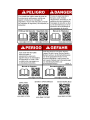 2
2
-
 3
3
-
 4
4
-
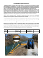 5
5
-
 6
6
-
 7
7
-
 8
8
-
 9
9
-
 10
10
-
 11
11
-
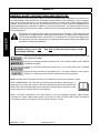 12
12
-
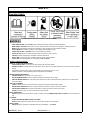 13
13
-
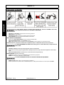 14
14
-
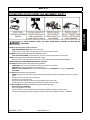 15
15
-
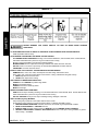 16
16
-
 17
17
-
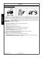 18
18
-
 19
19
-
 20
20
-
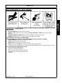 21
21
-
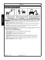 22
22
-
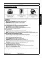 23
23
-
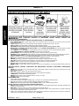 24
24
-
 25
25
-
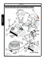 26
26
-
 27
27
-
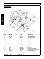 28
28
-
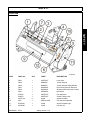 29
29
-
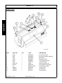 30
30
-
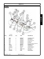 31
31
-
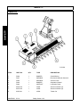 32
32
-
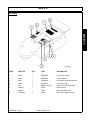 33
33
-
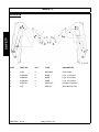 34
34
-
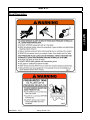 35
35
-
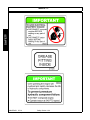 36
36
-
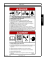 37
37
-
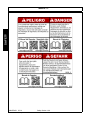 38
38
-
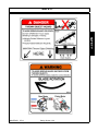 39
39
-
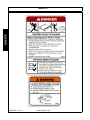 40
40
-
 41
41
-
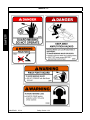 42
42
-
 43
43
-
 44
44
-
 45
45
-
 46
46
-
 47
47
-
 48
48
-
 49
49
-
 50
50
-
 51
51
-
 52
52
-
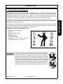 53
53
-
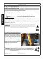 54
54
-
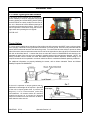 55
55
-
 56
56
-
 57
57
-
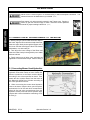 58
58
-
 59
59
-
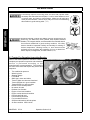 60
60
-
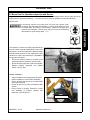 61
61
-
 62
62
-
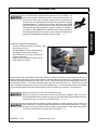 63
63
-
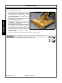 64
64
-
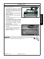 65
65
-
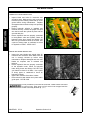 66
66
-
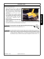 67
67
-
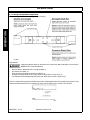 68
68
-
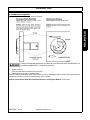 69
69
-
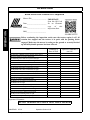 70
70
-
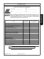 71
71
-
 72
72
-
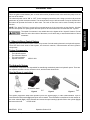 73
73
-
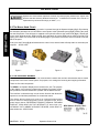 74
74
-
 75
75
-
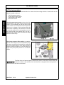 76
76
-
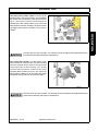 77
77
-
 78
78
-
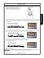 79
79
-
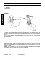 80
80
-
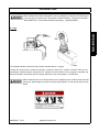 81
81
-
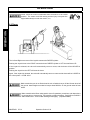 82
82
-
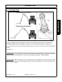 83
83
-
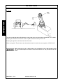 84
84
-
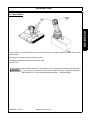 85
85
-
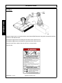 86
86
-
 87
87
-
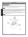 88
88
-
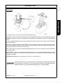 89
89
-
 90
90
-
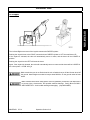 91
91
-
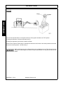 92
92
-
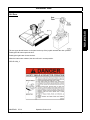 93
93
-
 94
94
-
 95
95
-
 96
96
-
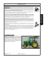 97
97
-
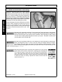 98
98
-
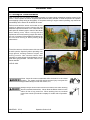 99
99
-
 100
100
-
 101
101
-
 102
102
-
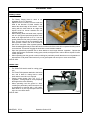 103
103
-
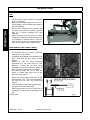 104
104
-
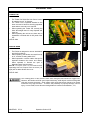 105
105
-
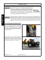 106
106
-
 107
107
-
 108
108
-
 109
109
-
 110
110
-
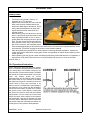 111
111
-
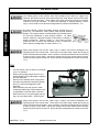 112
112
-
 113
113
-
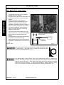 114
114
-
 115
115
-
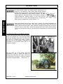 116
116
-
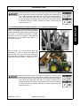 117
117
-
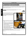 118
118
-
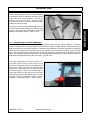 119
119
-
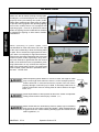 120
120
-
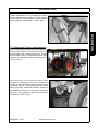 121
121
-
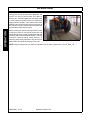 122
122
-
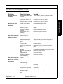 123
123
-
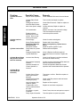 124
124
-
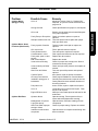 125
125
-
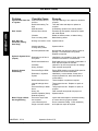 126
126
-
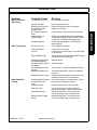 127
127
-
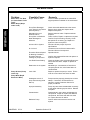 128
128
-
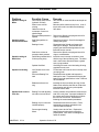 129
129
-
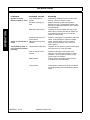 130
130
-
 131
131
-
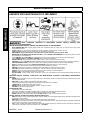 132
132
-
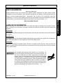 133
133
-
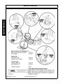 134
134
-
 135
135
-
 136
136
-
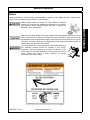 137
137
-
 138
138
-
 139
139
-
 140
140
-
 141
141
-
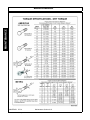 142
142
-
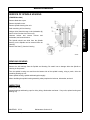 143
143
-
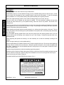 144
144
-
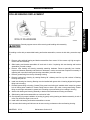 145
145
-
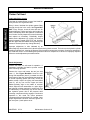 146
146
-
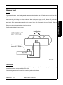 147
147
-
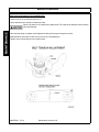 148
148
-
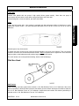 149
149
-
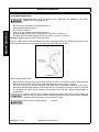 150
150
-
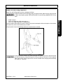 151
151
-
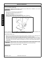 152
152
-
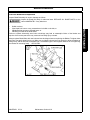 153
153
-
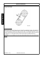 154
154
-
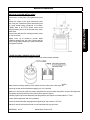 155
155
-
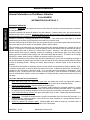 156
156
-
 157
157
-
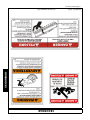 158
158
-
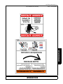 159
159
-
 160
160
-
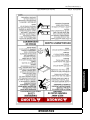 161
161
-
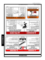 162
162
-
 163
163
-
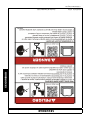 164
164
-
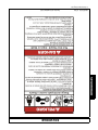 165
165
-
 166
166
-
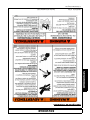 167
167
-
 168
168
-
 169
169
-
 170
170
-
 171
171
-
 172
172
-
 173
173
-
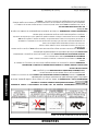 174
174
-
 175
175
-
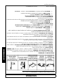 176
176
-
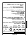 177
177
-
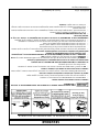 178
178
-
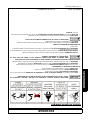 179
179
-
 180
180
-
 181
181
-
 182
182
-
 183
183
-
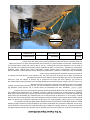 184
184
-
 185
185
-
 186
186
-
 187
187
-
 188
188


Alamo Industrial Maverick Boom Mower Manual de usuario
- Categoría
- Cortadoras de césped
- Tipo
- Manual de usuario
en otros idiomas
Artículos relacionados
-
Alamo Industrial Rear Mount Boom 165 & 180 Manual de usuario
-
-
-
-
-
-
-
-
-
Otros documentos
-
Bush Hog RMB Boom Mower El manual del propietario
-
-
Alamo RHINO 1900 Manual de usuario
-
Enerpac VE42A Repair Service Instructions
-
Ranger RGST-0P Guía de instalación
-
-
-
Land Rover L322 Range Rover Workshop Manual
-
 Pall UR329 Serie Service Instructions Manual
-
Silvercrest SGM 110 A1 El manual del propietario
