MAAX 106307-000-001-101 Manual de usuario
- Tipo
- Manual de usuario

INSTALLATION INSTRUCTIONS
GUÍA DE INSTALACIÓN
Read all instructions carefully before proceeding.
SAVE THIS GUIDE FOR FUTURE REFERENCE.
Leer detenidamente todas las instrucciones antes de
comenzar la instalación
CONSERVAR ESTE MANUAL COMO REFERENCIA.
Serial numbers • Números de serie
IMPORTANT • Record the serial numbers
IMPORTANTE • Registre el número de serie
A two person installation is required.
Se recomienda realizar la
instalación entre dos personas
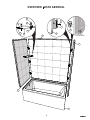
TUB SHOWER INSTALLATION (3 WALLS)
INSTALACIÓN DE BAÑERA DUCHA (3 MUROS)
HARDWARE INCLUDED
IN BOXES
HARDWARE INCLUIDO EN
LAS CAJAS
OPEN ALL BOXES
BEFORE YOU START
ABRIR TODAS LAS CAJAS
ANTES DE EMPEZAR
Ver video de instalación -
Escanear código QR con un
dispositivo móvil.
View Installation Video - Scan
QR code with a mobile device

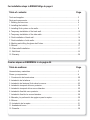
Table of contents: Page
Tools and supplies.............................................................................................................. 3
Parts and components........................................................................................................ 4
1. Building the structure..................................................................................................... 6
2. Installing the bathtub...................................................................................................... 7
3. Installing Ulok system on the walls............................................................................... 9
4. Temporary installation of the back wall........................................................................... 10
5. Temporary installation of the side walls...........................................................................11
6. Final installation of back wall.......................................................................................... 14
7. Final installation of side walls......................................................................................... 15
8. Marking and drilling the glass shelf holes..................................................................... 16
9. Silicone............................................................................................................................17
10. Glass shelf installation.................................................................................................. 17
11. Wall fi nish......................................................................................................................19
12. Warranty........................................................................................................................ 36
Table de matières: Page
Herramientas y materiales.................................................................................................. 3
Piezas y componentes........................................................................................................ 4
1. Construcción de la estructura......................................................................................... 20
2. Instalación de la bañera................................................................................................. 21
3. Instalación del sistema Ulok sobre los muros................................................................. 23
4. Instalación temporal del muro posterior.......................................................................... 24
5. Instalación temporal de los muros laterales................................................................... 25
6. Instalación fi nal del muro posterior................................................................................. 28
7. Instalación fi nal de los muros laterales........................................................................... 29
8. Marcado y la perforación de agujeros para la repisa...................................................... 30
9. Silicona............................................................................................................................31
10. Instalación de la repisa................................................................................................. 31
11. Acabado del muro......................................................................................................... 33
12. Garantía........................................................................................................................ 36
For installation steps in
ENGLISH
ENGLISH
go to page 6
Para las etapas en ESPAÑOL ir a la pagina 20

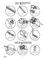
3
Screwdriver
Destornillador
TOOLS
REQUIRED
HERRAMIENTAS
REQUERIDAS
24" level min.
Nivel de 24" min.
Pencil
Lápiz
Clear silicone sealant
Sellador de silicona
transparente
Measuring tape
Cinta métrica
18" square min.
Escuadra de
18" min.
Utility knife
Cuchillo multiuso
Safety equipment
Equipo de
seguridad
Hole saw
Sierra de
perforación
1/8" drill bits
Brocas de 1/8
SUPPLIES
SOLD SEPARATELY
SUMINISTROS
VENDIDOS POR SEPARADO
Box of #8x1¾"
flathead screws
Caja de tornillos #8x1¾"
de cabeza plana
Wood shims
Cuñas de madera
50
Electric drill
Taladro eléctrico

4
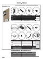
PARTS PIEZAS
6
1
43
2
109
8
5
11
# Part Pieza Qty/Cant. Code/Código
1 X fastener Sujetador en forma de X 8
10060303
2
#8 x 1¼’’ Screw (for X fastener) Tornillos #8 x 1¼’’ (Para sujetador en X) 8
3 Retraction pin Pasador de retracción 8
4
#8 x ⅜ Screw (for retraction pin)
Tornillos #8 x ⅜ (para
pasador de retracción)
8
7
# Part Pieza Qty/Cant. Code/Código
5 Glass shelf Repisa 1
10060011
6 Bracket Soporte de repisa 2
7
#10 x 2’’ screws Tornillos #10 x 1½’’ (repisa) 2
8
Plastic washer Adandela en plástico para repisa 2
9
Support cap Tapa de la fi jación de repisa 2
10 #10 x ½ screws Tornillos #10 x ½ (para repisa) 2
11
Allen key Llave allen 1
12 Template Plantilla de perforación 1
# Part Pieza Qty/Cant. Code
13 Bathtub Base 1 -
14 Back wall Muro posterior 1 -
15 Side Wall Muro lateral 2 -
PARTS INCLUDED IN PARTS PACK | PIEZAS INCLUIDAS EN PAQUETE DE PIEZAS
PARTS INCLUDED IN SHELF PACK | PIEZAS INCLUIDAS EN LA CAJA DE LA REPISA
12
Inside the box
En el interior de la caja
COMPONENTS COMPONENTES
www.maax.com
1
0
06
0
3
03 –
U
LO
K
Sk
in
p
ac
k f
o
r
U
t
il
e
-
1
ju
n
ct
io
n
3
1
2
4
B
A
CK
W
A
L
L
M
UR
AR
R
I
ÈR
E
MUR
O POST
E
R
IO
R
I
NSIDE VIEW
VUE
I
NT
ÉR
I
EUR
E
VIS
T
A
INTERIO
R
S
I
D
E
WALL
M
UR
DE
CÔ
T
É
M
U
R
O
L
A
TE
R
A
L
3
4
I
NS
I
D
E VIEW
V
U
E
I
NT
ÉR
I
EU
RE
VI
S
T
A
I
NT
E
RI
O
R
by
/
p
ar
M
A
A
X
*
Extr
a
pa
r
ts
a
r
e
inc
l
u
d
e
d
in
th
i
s
p
ac
k
in c
a
s
e
of lo
ss
or
dama
g
e
*
Des piè
c
es
supp
l
émen
t
air
e
s son
t
i
n
c
luse
s e
n ca
s d
e perte ou
b
r
is
* Piez
a
s ext
r
as están inclui
d
as en e
st
e e
m
pa
q
u
e
en c
a
so d
e
per
d
id
a o
daño
www.maax.com
1
0
0603
0
3
–
ULO
K
Skin
p
ack
f
o
r
U
til
e
-
1
jun
ct
i
on
3
1
2
4
BACK
W
ALL
M
U
R
ARR
I
ÈRE
M
U
R
O P
OSTE
R
IO
R
INS
IDE
VIE
W
VUE INTÉRIE
U
RE
VIS
T
A
INTERIOR
SIDE
W
A
LL
M
UR
DE
CÔ
T
É
M
UR
O
L
A
TE
R
A
L
3
4
INSI
DE
VI
EW
VUE
IN
TÉ
R
IE
URE
VI
S
T
A
I
N
T
ER
I
O
R
by
/par
M
AA
X
* Extra p
a
rts are included
i
n
this pack in c
ase
of
l
o
ss or dam
ag
e
* Des p
i
è
c
es supp
l
émen
t
aires
s
on
t
in
cl
u
ses
en
cas de perte ou br
i
s
*
Piez
as
extras están incl
u
i
da
s e
n
e
st
e e
m
pa
q
u
e
en c
a
so
d
e
pe
rdi
d
a o da
ñ
o

5
13
14
15
15
4
15
3
INSIDE VIEW
VISTA INTERIOR
5
9
10
8
7
6
1
2
14
OVERVIEW VISTA GENERAL

6
1
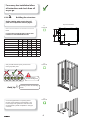
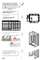
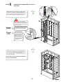
STEP Building the structure
Build a structure based on the dimensions in the chart
below.
IF STRUCTURE IS ALREADY BUILT CHECK THAT
IT RESPECTS THE DIMENSIONS BELOW
Verify the wall studs are square, plumb and the
fl ooring is perfectly level.
6"
6"
C
For a worry free installation follow
all instructions and check them off
as you go.
A
B
C
D
Top view of structure
1.1
Check me!
1.2
Check me!
1.3
Check me!
D
COMPATIBLE BATHTUBS No A B C D
COCOON 6030 IFS 105822
Between
60" - 60 1/4"
31 1/2"
min.
14 1/8" 9 3/8"
BROME 105821
Between
60" - 60 1/4"
31 1/2"
min.
14 1/8" 9 3/8"
EXHIBIT 6030 (IFS) 105519 59 3/4"
30"
min.
14" 10"
EXHIBIT 6030 (IFS) AFR 105511 59 3/4"
30"
min.
14" 10"
NEW TOWN 6030 IFS 105454
Between
60" - 60 1/4"
31 1/2"
min.
14" 10 1/8"
RUBIX 6030 105815 59 3/4"
30"
min.
18 3/8" 15"
RUBIX 6030 AFR 105816 59 3/4"
30"
min.
20 3/8" 15"
Leveling the fl oor is
critical for wall alignment
Quick tip
For leveling the fl oor use self-leveling
mortar.
Cut out an approximate 6" x 6" opening around
the drain center outlined by measurements C and
D. See image to the right and the chart above. We
recommend that a plumber completes the drain pipe
connection.
Before starting make sure to have all
parts and components refer to page 4.

7
2
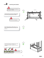
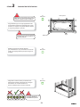
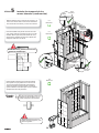
STEP Installing the bathtub
Install the bathtub (13) pushing it completely against
the back studs. Center the bathtub left to right inside
the alcove leaving equal spacing on both sides.
13
Leveling the bathtub is
critical for wall alignment
Verify that the bathtub is completely level on all sides.
Confi rm that the drain pipe is centered. We
recommend that a plumber completes the drain pipe
connection.
Centering the bathtub left to right is
critical for side wall installation.
13
Top view
Flush
2.1
Check me!
2.2
Check me!
2.3
Check me!
Studs
Connect plumbing (drain, overfl ow, faucets, etc.) ac-
cording to local standards and to general rules in the
bathtub installation guide. Make sure that all joints are
waterproof.
2
Remove clear plastic fi lm on the bathtub. Use
cardboard on the bathtub fl oor as protection until
the installation is complete.

8
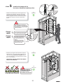
If needed use wood shims between the studs and
the fastening fl ange to maintain centered position of
bathtub.
DO NOT USE SHIMS UNDER THE BATHTUB TO
LEVEL!
DOING SO WILL VOID THE MAAX WARRANTY!
13
With a 1/8" bit, drill holes in the bathtub fastening
fl ange then secure the bathtub to all the wall studs
with #8 x 1¾ " screws (not included). Only pre-drill
the flange not the studs.
HAND TIGHTEN ONLY !
CUT SHIM EXCESS
13
2
STEP Installing the bathtub (cont'd)
2.4
Check me!
2.5
Check me!
Ø 1/8"
Fastening fl ange

9
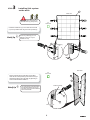
3
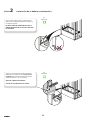
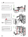
STEP Installing Ulok system
on the walls
Install three X fasteners (1) on each side of the back wall
(14) in the pre drilled holes using the screws provided (2).
Quick tip
There is a positioning pin on X
fastener so they can only be
installed one way.
14
Back wall
1
14
2
2
1
14
This side
down
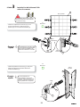
4
3
The side walls are interchangeable.
For left wall install the pins on the
right side, for the right wall install the
pins on the left side.
Quick tip
Side walls
15
15
Fastening fl ange
3.1
Check me!
3.2
Check me!
This side down
Positioning
pin
The Ulok system parts are in the
side wall boxes. (1 pack per box)
ww
w
.m
aax
.
c
om
10
0
60303 –
U
L
OK
Sk
i
n
p
ac
k
f
or
U
t
i
le
-
1
j
u
n
c
tion
3
1
2
4
BA
CK
W
A
L
L
MUR
A
RR
I
ÈRE
M
U
R
O
P
O
S
T
E
R
IO
R
IN
SI
D
E
V
I
EW
VUE I
NT
É
R
I
E
UR
E
V
I
S
T
A
IN
T
E
RI
OR
S
I
D
E
W
ALL
MU
R
D
E
CÔTÉ
MU
R
O
L
A
TE
R
A
L
3
4
I
N
S
I
D
E
V
I
EW
VUE
I
NT
ÉRI
E
U
R
E
V
IS
T
A
I
NT
E
R
I
O
R
by/
p
a
r
M
A
A
X
* Ext
ra
p
a
r
t
s
are
in
c
l
ud
e
d
in
t
h
is
pa
ck
in
c
a
s
e
o
f
l
os
s or
damage
*
D
es
p
ièces
su
pp
lé
m
en
t
a
ir
e
s
s
o
n
t
inclu
s
e
s
en c
as de
p
ert
e
ou
b
ris
* P
ie
z
as
ex
t
ra
s
e
s
t
á
n
in
c
lu
id
a
s
e
n
e
s
t
e
emp
a
que
e
n
c
a
s
o
d
e
p
e
r
di
d
a
o
d
año
ww
w.
maax
.
com
1
0
0
6
0
3
0
3
–
U
LOK
Sk
in
p
ac
k
fo
r
U
ti
le
-
1
ju
n
cti
o
n
3
1
2
4
BA
CK
W
ALL
M
UR
A
R
RIÈ
RE
M
U
R
O
P
OS
T
E
R
I
O
R
I
NS
I
D
E
V
I
E
W
V
U
E I
N
T
É
RI
E
UR
E
VI
S
T
A
I
NT
E
R
I
O
R
S
I
D
E
W
A
LL
M
UR
D
E
CÔ
T
É
M
U
R
O
L
A
T
E
R
A
L
3
4
I
N
S
I
D
E VIE
W
V
UE
I
N
T
ÉR
I
EU
R
E
V
I
S
T
A
INT
ERI
O
R
by
/
par
M
AA
X
*
Ext
ra
part
s
ar
e
i
nclude
d
i
n
this
pa
ck
in
c
a
s
e o
f
lo
s
s
o
r
d
amag
e
*
D
es
piè
c
es s
upp
lémentair
e
s
s
o
nt inc
l
use
s
e
n
c
a
s
de
pe
rte
o
u b
ris
*
Piez
a
s
e
x
tras
e
stá
n
inclu
id
as
en es
te
e
m
p
aq
u
e
en c
aso d
e
p
erd
i
d
a o da
ñ
o
Fasten 3 retraction pins per side wall in the pre drilled
holes with the screws provided (4) to the left-hand or right-
hand fastening fl ange of the side walls (15) depending on
which side the wall will be installed on.

10
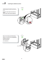
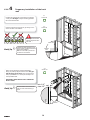
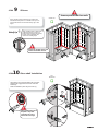
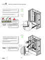
4
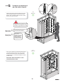
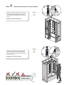
STEP Temporary installation of the back
wall
Quick tip
Installing the walls temporarily will
ensure proper wall alignment before
permanent installation.
Make sure the wall is plumb and
centered on the bathtub.
With a 1/8" bit, drill holes in the back wall fastening
flange (14) at the top aligned with each stud. Only pre-
drill the flange not the studs. Then, secure the back
wall (14) with one #8 x 1¾" screw (not included) in one
of the pre-drilled holes.
IMPORTANT: HAND TIGHTEN ONLY. TEMPORARY
INSTALLATION.
Quick tip
Push the bottom of the back wall
with your foot when fastening in
place.
Plumbing the back wall is
critical for alignment of the
side walls
14
Bathtub
deck
Back wall
Position and level the back wall (14) by sitting it on the
deck at the back of the bathtub.
4.1
Check me!
4.2
Check me!
4.3
Check me!
Pull back the protective fi lm on the walls (14-15) at least
3" away from all edges. Keep the remaining protective
fi lm on the walls and base.
min.3/16"
max.3/8"
Stud
X fastener

11
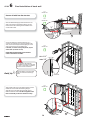
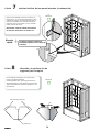
Install the side wall (15) on the opposite side of the
faucet installation. Lift the wall approximately 3" above
the deck of the bathtub, push it completely against the
back wall then lower the side wall into position.
The side wall should now line up
with the front of the bathtub.
Quick tip
Bathtub
Side wall
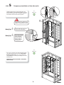
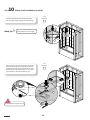
With a 1/8" bit, drill holes in the side wall fastening flange
(15) at the top aligned with each stud. Only pre-drill
the flange not the studs. Then, secure the side wall
(15) with one #8 x 1¾" screw (not included) in one of the
pre-drilled holes.
IMPORTANT: HAND TIGHTEN ONLY. TEMPORARY
INSTALLATION.
3
1
Side wall
Back wall
It is critical that all 3 retraction pins
engage with the X fasteners. There
should be no gap between the walls.
5
STEP Temporary installation of the side walls
Quick tip
Place a level vertically
on the side wall. If the
wall is not straight,
make sure that the
retraction pins are
properly inserted in
the X fasteners.
5.1
Check me!
5.2
Check me!
15

12
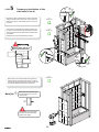
5
STEP Temporary installation of the
side walls (Cont'd)
Measure the distance between the front face of the back
wall (14) and the center of the faucet. Then measure the
distance from the top of the bathtub deck to the center of
the faucet.
Quick tip
Hole saws can be rented at your
local hardware store or any tool
rental location.
Faucet
center
Using those two measurements mark the position of the
faucet hole on the remaining side wall. Measure from the
side and bottom of the side wall where the retraction pins
are installed.
Repeat this process for all required faucet holes.
5.4
Check me!
5.3
Check me!
5.5
Check me!
Back
wall
Top view
Bathtub
deck
Front cut
view
For safe hole saw usage always
pre-drill a hole and wear safety
glasses when drilling.
Drill a hole from front for the faucets at the previously
marked positions. Pre-drill the hole with the ⅛'' drill bit.
The hole saw size is determined by the faucet type; refer
to the faucet installation manual for hole saw size.
Measure twice, drill once !
Record measures below.

13
Install the side wall (15) with the drilled faucet hole(s).
Lift the wall approximately 3" above the deck of the
bathtub, push it completely against the back wall then
lower the side wall into position.
Quick tip
With a 1/8" bit, drill holes in the side wall fastening flange
(15) at the top aligned with each stud. Only pre-drill
the flange not the studs. Then, secure the side wall
(15) with one #8 x 1¼" screw (not included) in one of the
pre-drilled holes.
IMPORTANT: HAND TIGHTEN ONLY. DO NOT
OVER-TIGHTEN THE SCREW.
3
1
Side wall
Back wall
Bathtub
Side wall
5
STEP Temporary installation of
the side walls (Cont'd)
The side wall should now line up
with the front of the bathtub.
Quick tip
Place a level
vertically on the side
wall. If the wall is not
straight, make sure
that the x-fasteners
are properly inserted
5.6
Check me!
5.7
Check me!
It is critical that all 3 retraction pins
engage with the X fasteners. There
should be no gap between the walls.
Deck

14
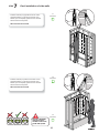
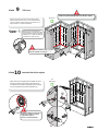
6
STEP Final installation of back wall
Quick tip
Hold the bottom of the back wall
with your foot when fastening in
place.
13
13
⅜"
Bathtub
Back
wall
14
min.3/16"
max.3/8"
Stud
X fastener
It is critical for the side wall
installation for there to be at least
⅛'' and no more than ⅜" between
the stud and the X fastener.
6.1
Check me!
6.3
Check me!
6.4
Check me!
Remove all walls from the structure.
Clean the bathtub and apply a bead of silicone on the
deck at 3/8" from the back fastening flange. Run the
bead of silicone the entire length of the bathtub and 1''
on each side as well.
6.2
Check me!
Apply a bead of silicone on both sides of base (13) thres-
hold at 3/8" from the base side fastening flanges.
Apply silicone on both side of the back wall (14) just
before the wall side radius. The silicone applied on the
base and vertically on the back wall must overlap.
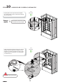
Secure the wall to the wall studs with #8 x 1¾ "
screws (not included) in the previously drilled holes.
Also, secure the wall by the fastening fl anges on the
side of the wall. Use the pre-dilled holes.
If needed, use shims to keep wall plumb, square
and leveled. (Cut shim excess)
IMPORTANT: HAND TIGHTEN ONLY. DO NOT
OVER-TIGHTEN THE SCREWS.
⅜"
⅜"
1"

15
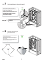
Install the side wall (15) opposite the faucet. Lift the
wall approximately 3 inches above the deck of the
bathtub, push it completely against the back wall then
slide the side wall into position.
WIPE OFF EXCESS SILICONE
3
1
Side wall
Back wall
7
STEP Final installation of side walls
Install the side wall (15) with the faucet hole. Lift the
wall approximately 3 inches above the deck of the
bathtub, push it completely against the back wall then
slide the side wall into position.
WIPE OFF EXCESS SILICONE
3
1
Side wall
Back wall
7.1
Check me!
7.2
Check me!
7.3
Check me!
BEFORE CONTINUING,
VALIDATE THAT ALL
THE WALLS ARE LEVEL,
PLUMB AND SQUARE

16
7
STEP Final installation of side walls (cont'd)
Secure the walls to the wall studs with #8 x 1¾ "
screws (not included) in the previously drilled holes.
Also, secure the walls by the fl anges on the sides of
the walls. Use the pre-dilled holes.
If needed, use shims to keep walls plumb, square
and leveled. (Cut shim excess)
IMPORTANT: HAND TIGHTEN ONLY. DO NOT
OVER-TIGHTEN THE SCREWS.
Check me!
Place the template in the corner of the shower where
you want to install your shelf.
Slide the template up until the points on the left and
right-hand side of the template are at the height you
want your shelf.
Use a pencil, marker or wax pencil to mark the spots
where the holes for the shelf will be drilled.
Drill the holes using a 9/64" drill bit.
8
STEP Marking and drilling the
glass shelf holes
Fold here
Drilling positions
Bathtub
Side wall
THE SIDE WALLS SHOULD LINE UP WITH
THE BATHTUB
Quick tip
90°
7.4
Check me!

17
Quick tip
Apply masking tape on both sides
of the joint where you will run a
bead of silicone. Apply the silicone,
smooth with a wet fi nger then
remove the masking tape.
Check me!
Apply a bead of silicone all along the wall to wall
and wall to base joints. For a smooth fi nish you can
remove the silicone excess with a damp rag or wet
fi nger.
9
STEP Silicone
Apply silicone in the previously drilled holes on the side
and back walls. Apply silicone to the rear of the shelf
brackets (6).
Fasten the brackets in place using the screws (7).
10
STEP Glass shelf installation
7
6
6
10.1
Check me!
All faucets installed on the walls
must be sealed with silicone.
Remove protective fi lm from walls
When installing the faucet
faceplate or any other
component, be sure to
silicone the outer edge.

18
Clean the top rubber part of the brackets with a damp
cloth, then place the glass shelf (5) over the brackets (6).
5
6
6
Insert the washers (8) in the shelf support cap (9). Align
and insert the shelf support caps (9) with the holes of
the glass and the holes of the shelf brackets (6). Screw
from the bottom of the shelf with the # 10 x ½'' screws
(10) and tighten by hand with the Allen key (11).
9
10
6
8
11
7
10
STEP Glass shelf installation (cont'd)
Quick tip
If you can read the MAAX logo, the
shelf is installed on the right side.
Align oblong holes
10.2
Check me!
10.3
Check me!
Do not overtight the support cap (9)

19
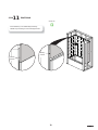
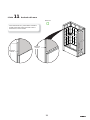
For the wall fi nish you can install install your fi nishing
material on top of the fl ange or on the wall edge as shown.
11
STEP Wall fi nish
Check me!
Finishing
material
Finishing
material

20
6"
6"
C
D
A
B
C
D
BAÑERAS COMPATIBLES No A B C D
COCOON 6030 IFS 105822
Entre
60" - 60 1/4"
31 1/2"
min.
14 1/8" 9 3/8"
BROME 105821
Entre
60" - 60 1/4"
31 1/2"
min.
14 1/8" 9 3/8"
EXHIBIT 6030 (IFS) 105519 59 3/4"
30"
min.
14" 10"
EXHIBIT 6030 (IFS) AFR 105511 59 3/4"
30"
min.
14" 10"
NEW TOWN 6030 IFS 105454
Entre
60" - 60 1/4"
31 1/2"
min.
14" 10 1/8"
RUBIX 6030 105815 59 3/4"
30"
min.
18 3/8" 15"
RUBIX 6030 AFR 105816 59 3/4"
30"
min.
20 3/8" 15"
Verifi car que los listones esten a escuadra y verticales
y que el piso este a nivel.
En las bases con espuma reforzada
(Olympia), utilizar mortero autonive-
lante para nivelar el piso.
Para una instalación sin problemas
siga las etapas una a una y vaya y
marquelas una vez estén terminadas.
Corte una abertura de aproximadamente 6 x 6 para
el desagüe central, siguiendo las medidas C y D. Ver
la imagen de la derecha y de la tabla en el paso 1.1.
Recomendamos contratar a un plomero certifi cado
para conectar el desagüe.
Vista superior de la estructura
Es esencial que el suelo
esté a nivel para garanti-
zar la verticalidad de las
paredes a instalar.
1.1
Marcarme!
1.2
Marcarme!
1.3
Marcarme!
1
ETAPA Construcción de la
estructura
Contruir una estructura que respete las dimensiones
mencionadas en la tabla.
SI LA ESTRUCTURA YA ESTA CONSTRUIDA,
ASEGURARSE QUE LAS DIMENSIONES
RESPETEN LAS DE LA TABLA
Cti t t tl di i
Antes de comenzar asegurese de tener
todas las piezas y componentes
referirse a la página 4.

Es esencial que la bañera este
a nivel para garantizar la
verticalidad de las paredes.
21
2
ETAPA Instalación de la bañera
13
13
2.3
Marcarme!
Realizar la conexión de la tubería (desagüe,
grifo, desbordamiento, etc.) de acuerdo con las normas
locales y las reglas generales al principio de la guía de
la bañera.
Ponga la bañera (13) en su lugar apoyandola contra
los montantes o listones de la pared del fondo. Centre
la bañera con respecto a las paredes laterales dejando
un espacio equivalente a cada lado.
Es esencial centrar muy bien la bañera
para asegurar la correcta instalación de
las paredes laterales.
Vista superior
2.1
Marcarme!
2.2
Marcarme!
Montantes
Retire la película transparente de la bañera.
Utilice cartón en el fondo de la bañera como
protección hasta el fi nal de la instalación.
Asegúrarse en todos los lados que la bañera esta
perfectamente nivelada. Comprobar que el desagüe
está alineado. Se recomienda utilizar una
plomero certifi cado para la conexión de drenaje.

22
13
13
2
ETAPA Instalación de la bañera (continuación)
Ø 1/8"
Brida
Si es necesario, utilizar cuñas de madera entre la
bañera y los montantes para mantener la bañera en
una posición centrada.
NO USAR CUÑAS DE MADERA DEBAJO DE LA
BAÑERA PARA NIVELARLA; HACERLO ANULARÁ
LA GARANTÍA!
Br
Perforar los pre-agujeros de la brida de la bañera
solamente con una broca de 1/8". No perforar los
montantes. Fijar la bañera a todos los montantes
usando tornillos # 8 x 1 ¾" (no incluidos).
APRETAR A MANO ÚNICAMENTE!
CORTAR EL EXCEDENTE DE LAS CUÑAS.
2.4
Marcarme!
2.5
Marcarme!

23
14
1
14
2
2
1
14
4
3
15
15
Bride
3
ETAPA Instalación del sistema Ulok
sobre los muros
Instalar tres sujetadores en forma de X (1) en los
agujeros preperforados a cada lado del muro
posterior (14) con los tornillos suministrados (2).
Los sujetadores en forma de X dispo-
nen de una barra de posicionamiento
para ayudar a su instalación, solo
pueden ser instalados en un sentido.
Muro posterior
Este lado
hacia abajo
Instalar tres pasadores de retracción (3) por cada pared
lateral en los agujeros pre-perforados utilizando los
tornillos suministrados (4).
Los muros laterales son
intercambiables. Para el muro
izquierdo, fi jar los pasadores a la
derecha, y para el muro derecho,
fi jar los pasadores a la izquierda.
Muros
laterales
Brida
3.1
Marcarme!
3.2
Marcarme!
Las piezas del sistema Ulok se encuen-
tran en las cajas de los muros laterales
(un paquete por caja)
Este lado
hacia abajo
Consejo
rápido
Consejo
rápido
barra de
posicionamiento
www.m
a
ax.
co
m
1
0
0
6
0303
–
U
LO
K
S
ki
n pac
k
fo
r
U
ti
le
-
1
j
u
nct
ion
3
1
2
4
BA
C
K
W
A
L
L
M
UR
ARRIÈ
R
E
M
UR
O
P
OS
TE
R
IO
R
I
NS
I
D
E
VI
E
W
V
UE
I
NT
É
R
I
EU
R
E
V
I
S
T
A
IN
T
E
RIO
R
SI
D
E
W
A
L
L
M
UR D
E
CÔ
T
É
M
UR
O
L
A
TE
R
A
L
3
4
I
NS
IDE
VI
E
W
V
U
E I
N
TÉ
RI
E
URE
VI
S
T
A
I
NTER
I
O
R
by
/pa
r
M
A
A
X
* E
xtra
p
art
s
ar
e
inc
l
u
d
ed
i
n t
h
is
p
a
c
k
in cas
e
of
loss
o
r dama
g
e
*
D
e
s
p
iè
c
e
s
s
uppl
é
mentai
r
es
s
o
n
t
inclu
se
s
e
n
c
as
d
e
p
e
rt
e
ou b
ris
*
P
ie
z
a
s e
x
t
ra
s
e
st
á
n
i
ncluidas
en es
te e
m
p
aq
u
e
e
n
ca
so
d
e
pe
rd
id
a
o
d
a
ñ
o
www
.maa
x.
com
1006030
3
–
U
L
O
K
Sk
in
pack
f
o
r
U
ti
le
-
1
junc
t
i
o
n
3
1
2
4
B
A
CK
W
A
L
L
MUR
A
R
RI
È
R
E
M
UR
O
P
O
STE
R
IO
R
I
NS
I
D
E V
I
EW
VU
E I
NT
É
R
I
E
U
R
E
V
I
S
T
A
I
NTER
I
O
R
SI
D
E
WALL
MU
R
D
E CÔTÉ
M
U
R
O
L
A
TE
R
A
L
3
4
I
NS
I
D
E
VI
EW
V
UE
I
NT
É
RI
EUR
E
VIS
T
A I
N
TE
R
I
O
R
b
y
/par
M
A
A
X
*
Ex
tra par
t
s
are
in
clud
ed
in
th
i
s
p
a
c
k
i
n
case
o
f
lo
s
s
or
d
a
m
a
ge
*
De
s
p
iè
c
e
s
s
u
pp
l
éme
n
ta
i
res
s
ont
in
cl
us
e
s
e
n
c
a
s
d
e
p
e
r
t
e
o
u
b
ris
*
Piez
a
s
e
x
tras
e
stán
in
cluidas
en
es
te e
mp
aque
e
n
ca
s
o
d
e
p
erd
id
a
o
d
a
ñ
o

24
14
Reborde de la
bañera
Muro posterior
min.3/16"
max.3/8"
4
ETAPA Instalación temporal del muro posterior
Retirar al menos 3 o 4 pulgadas de película transparente
de todos los lados de la pared posterior. Deje el resto de
la película adherida a la pared.
La instalación temporal de los
muros garantiza su alineación cor-
recta antes de instalarlos de manera
permanente.
Empuje la parte inferior del muro
contra los montantes con el pie en
el momento de atornillar el muro en
su lugar.
Es esencial nivelar
el muro porterior para
garantizar el
alineamiento de los
muros laterales.
Coloque el muro posterior (14) apoyandolo en el
reborde posterior de la bañera y nivelarlo.
4.1
Marcarme!
4.2
Marcarme!
4.3
Marcarme!
Consejo
rápido
Consejo
rápido
Perforar los pre-agujeros de la brida del muro posterior
solamente con una broca de 1/8" alineando con cada
montante. No perforar los montantes. Fijar el muro
temporalmente a un montante usando un tornillo # 8 x
1 ¾" (no incluido).
IMPORTANTE: APRETAR A MANO ÚNICAMENTE!
INSTALACIÓN TEMPORAL.
Montante
Sujetador en
forma de X

25
Baignoire
Mur de
côté
3
1
Mur de
côté
Mur arrière
15
Instalar el primer muro lateral (15) en el lado opuesto
de la válvula. Coloque el muro aproximadamente 3
pulgadas por encima del reborde de la bañera, empu-
jando con fuerza contra el muro posterior, a continua-
ción, bajar el muro sobre el reborde de la bañera.
El muro lateral debe estar alineado
con la parte frontal de la bañera.
Es esencial que los pasadores
estén completamente insertados en
los sujetadores en X. No debe haber
ningún espacio entre el muro lateral
y el muro posterior.
5
ETAPA Instalación temporal de los muros
laterales
Comprobar la vertica-
lidad de la pared lateral
usando un nivel. Si la
pared no es vertical,
asegurarse que los pa-
sadores de retracción
están bien insertados
en los sujetadores en
forma de X.
5.1
Marcarme!
5.2
Marcarme!
Consejo
rápido
Consejo
rápido
Perforar los pre-agujeros de la brida del muro lateral
solamente (15), con una broca de 1/8" alineando con
cada montante. No perforar los montantes. Fijar el
muro temporalmente a un montante usando un tornillo
# 8 x 1 ¾" (no incluido).
IMPORTANTE: APRETAR A MANO ÚNICAMENTE!
INSTALACIÓN TEMPORAL.

26
5
ETAPA Instalación temporal de los
muros laterales (continuación)
Medir la distancia entre la cara del muro posterior y el
centro de la válvula. Medir a continuación la distancia
entre el reborde de la bañera y el centro de la válvula.
Perforar desde el frente los huecos para las válvulas:
Hacer primero una pre perforación con una broca de
1/8". Usar una sierra de perforación para perforar el
orifi cio de la válvula en el sitio marcado. Consultar la
guía de instalación de la válvula para conocer el tamaño
apropiado de la sierra de perforación.
Las sierra de perforación pueden ser
alquiladas en las ferreterías o en los
locales de alquiler de herramientas.
Centro de
la válvula
Pasar las medidas de la posición del hueco de la vál-
vula y marcar subre el muro lateral que aun no ha sido
instalado. Medir a partir de la parte inferior del muro y
del lado de los pasadores de retracción. Repetir esta
etapa para cada hueco de válvula.
5.4
Marcarme!
5.3
Marcarme!
5.5
Marcarme!
Vista frontal
de corte
Muro
posterior
Vista
superior
Para una perforación segura: Pre-
perforar siempre los agujeros y usar
gafas de seguridad.
Consejo
rápido
Medir dos veces, perforar una sola vez!
Anotar las medidas aquí.
Reborde de la
bañera

27
3
1
Bañera
Mur arrière
Reborde
Es esencial que los pasadores
estén completamente insertados en
los sujetadores en X. No debe haber
ningún espacio entre el muro lateral
y el muro posterior.
ANTES DE CONTINUAR,
ASEGURARSE QUE TODOS
LOS MUROS ESTÁN A
ESCUADRA Y VERTICALES.
5
ETAPA Instalación temporal de
los muros laterales (continuación)
El muro lateral debe estar alineado
con la parte frontal de la bañera.
5.6
Marcarme!
5.7
Marcarme!
5.8
Marcarme!
Muro
Muro posterior
Muro
lateral
Consejo
rápido
Consejo
rápido
Instalar el muro lateral (15) una vez los agujeros de la
válvula han sido perforados. Coloque el muro aproxi-
madamente 3 pulgadas por encima del reborde de la
bañera, empujando con fuerza contra el muro posterior,
a continuación, bajar el muro sobre el reborde de la
bañera.
Comprobar la verticalidad
de la pared lateral usando
un nivel. Si la pared no es
vertical,
asegurarse que los pasa-
dores de retracción están
bien insertados en los suje-
tadores en forma de X.
Perforar los pre-agujeros de la brida del muro lateral
solamente (15), con una broca de 1/8" alineando con
cada montante. No perforar los montantes. Fijar el
muro temporalmente a un montante usando un tornillo
# 8 x 1 ¾" (no incluido).
IMPORTANTE: APRETAR A MANO ÚNICAMENTE!
INSTALACIÓN TEMPORAL.

28
13
14
min.3/16"
max.3/8"
Montant
13
⅜"
⅜"
1"
⅜"
Bañera
6
ETAPA Instalación fi nal del muro posterior
Retirar todos los muros de la estructura.
Levantar y colocar en su lugar el muro posterior (sin
deslizarlo) directamente sobre la silicona. Asegurarse
que el muro posterior (14) esta a nivel, agregar cuñas de
madera en caso de ser necesario. Fijar el muro a todos
los montantes con tornillos #8 x 1–¾" (no incluidos).
IMPORTANTE: APRETAR A MANO ÚNICAMENTE!
INSTALACIÓN TEMPORAL.
De cada lado de la bañera (13) aplicar una línea de
silicona sobre toda la longitud del reborde, a 1/4" de la
brida.
Aplicar también una línea de silicona de arriba hasta
abajo del muro posterior (14), sobre la superficie frontal
y al borde redondeado. En la unión entre el muro
posterior y la bañera las líneas de silicona deben
encontrarse.
Muro
posterior
6.1
Marcarme!
6.3
Marcarme!
6.4
Marcarme!
Limpiar la base y aplicar una línea de silicona en el
reborde de la bañera a 3/8" de la brida trasera. Aplicar
silicona sobre toda la longitud trasera y alrededor de 1
pulgada por lado.
6.2
Marcarme!
Empuje la parte inferior del muro
contra los montantes con el pie en
el momento de atornillar el muro en
su lugar.
Consejo
rápido
Para asegurar la instalación de los
muros laterales, debe haber un es-
pacio mínimo de 3/16" y un máximo
de 3/8" entre los montantes y los
sujetadores en X.
Sujetador
en X

29
3
1
3
1
Instalar el muro lateral (15) opuesto al de la válvula.
Poner el muro a aproximadamente 3" por encima del
reborde de la bañera, empujarlo a fondo contra el
muro posterior y descenderlo sobre el reborde de la
bañera.
RETIRAR EL EXCESO DE SILICONA.
7
ETAPA Instalación fi nal de los muros laterales
7.1
Marcarme!
7.2
Marcarme!
7.3
Marcarme!
Muro
lateral
Muro posterior
Muro
lateral
Muro posterior
Instalar el muro lateral (15) que tiene los agujeros
de la válvula. Poner el muro a aproximadamente 3"
por encima del reborde de la bañera, empujarlo a
fondo contra el muro posterior y descenderlo sobre el
reborde de la bañera.
RETIRAR EL EXCESO DE SILICONA.
ANTES DE CONTINUAR,
ASEGURARSE QUE TODOS
LOS MUROS ESTÁN A
ESCUADRA Y VERTICALES.

30
Bañera
Muro lateral
90°
7
ETAPA Instalación fi nal de los muros laterales (continuación)
Fijar los muros laterales a todos los montantes con
tornillos #8 x 1–¾" (no incluidos). Asegurar los muros
utilisando los agujeros pre-perforados de la brida. En
caso de ser necesario, usar cuñas de madera para
asegurarse que los muros están a nivel y verticales.
(Cortar el exceso de cuñas)
IMPORTANTE: APRETAR A MANO UNICAMENTE.
NO APRETAR DEMASIADO LOS TORNILLOS.
7.4
Marcarme!
Marcarme!
Poner la plantilla de perforación en la esquina de la
ducha, en la ubicación deseada.
deslizar la plantilla hasta que los agujeros estén a la
altura deseada para la repisa. Marcar la ubicación de los
ajujeros para perforación. Perforar los agujeros con una
broca de 6/64".
8
ETAPA Marcado y la perforación de
agujeros para la repisa
Plegar aquí
Posiciones de perforación
LOS MUROS LATERALES TIENEN QUE
ESTAR BIEN ALINEADOS CON EL FRENTE DE
LA BAÑERA
Consejo
rápido

31
7
6
6
Aplicar cinta de enmascarar de
cada lado de la unión donde la silico-
na será aplicada. Aplicar la silicona,
emparejar con un dedo humedecido,
a continuación retirar la cinta.
Marcarme!
Aplicar una línea de silicona sobre toda la longitud
de las uniones (muro a muro y muro a bañera). Para
un buen acabado, retirar el exceso de silicona con un
trapo humedo o un dedo humedecido.
9
ETAPA Silicona
Consejo
rápido
Toda grifería instalada sobre los muros
debe ser sellada con silicona.
Retirar la película de protección de los muros
Aplicar silicona en los agujeros del muro lateral y del muro
posterior que serviran para instalar la repisa. Aplicar sili-
cona detras de los soportes de repisa (6). Fijar los soportes
a los muros utilisando los tornillos suministrados (7).
10
ETAPA Instalación de la repisa
10.1
Marcarme!
Durante la instalación de la placa
frontal de la válvula o de otros
componentes, aplicar
silicona en el borde exterior.

32
5
6
6
9
10
6
8
11
7
Limpiar la parte en caucho por encima de los soportes
con un trapo humedo. Colocar a continuación la repisa (5)
sobre los soportes (6).
Insertar las tapas de la fi jación de repisa (9) en las aran-
delas (8). Alinear los agujeros de la repisa y los de los
soportes (6) e insertar el ensamble de la tapa (9). Bajo
la repisa, insertar los tornillos #10 x 1/2" (10) y apretar
con la llave allen (11).
10
ETAPA Instalación de la tableta (continuación)
La repisa esta en la posición correcta
si es posible leer el logo de MAAX.
Alinear las ranuras
10.2
Marcarme!
10.3
Marcarme!
No apretar la tapa (9) demasiado
Consejo
rápido

33
Para el acabado del muro, puede instalar su material de
acabado sobre la parte superior de la brida o sobre el
borde del muro, como se muestra.
11
ETAPA Acabado del muro
Marcarme!
Material de
acabado
Material de
acabado

34

35

© 2008 MAAX Bath Inc. PRINTED IN CANADA / IMPRESO EN CANADA 2016-05-03 10036975
Technical Services / Servicio técnico
T. 1 877 GET-MAAX (1 877 438-6229)
F. 1 888 361-2045
www.maax.com
LIMITED WARRANTY
MAAX Bath Inc. (hereafter “MAAX”) offers an
express limited warranty on each of its products.
This warranty extends only to the original
owner/end-user for personal household use. For
commercial uses, additional limitations apply.
MAAX warrants U tile wall units to be free of all
material or workmanship defects under normal
use and service for a period of ten (10) years from
the initial date of purchase by the owner/end-user,
contractor or builder from an authorized dealer.
This warranty extends to the original consumer
owner, but does not cover installation or any other
labour charges.
Except in the case of MAAX products with
pre-plumbed fixtures, MAAX shall in no event
be liable for damages of any kind when the
installation of jets or any other fixtures related
to the product is done by the customer or the
customer appointed installer.
MAAX reserves the right to modify this warranty
at any time, it being understood that such
modifi cation will not alter the warranty conditions
applicable at the time of the sale of the products
in question.
In order to obtain service provided under this
warranty during regular business hours, contact
the dealer or distributor who sold the unit, or
MAAX directly.
For more information on MAAX’s limited
warranty, please visit www.maax.com.
GARANTÍA LIMITADA
MAAX Bath Inc. (a continuación “MAAX”) ofrece
un garantía limitada expresa para cada uno de sus
productos. Esta garantía va dirigida únicamente al
propietario o al usuario original para un uso personal
doméstico. En caso de uso comercial, se aplican otras
restricciones.
MAAX garantiza las unidades U tile contra
cualquier defecto de material o de fabricación
en condiciones normales de utilización y
mantenimiento durante un periodo de diez (10)
años a partir de la fecha de compra original del
producto por parte del propietario o usuario,
el contratista o el constructor en un comercio
minorista autorizado.
La presente garantía se extiende al consumidor o
usuario original, pero no se aplica a la instalación
o a cualquier otro costo de mano de obra.
Salvo en el caso de productos de MAAX con
accesorios de plomería pre-instalados, MAAX
no será responsable bajo circunstancia alguna
por ningún tipo de daño cuando la instalación de
los chorros (jets) o de cualquier otro accesorio
relacionado con el producto sea realizada por el
cliente mismo o por un instalador designado por
el cliente.
MAAX se reserva el derecho de modifi car esta
garantía en cualquier momento; se sobreentiende
que dichas modifi caciones no cambiarán las
condiciones de la garantía que se apliquen en el
momento de la venta de los productos en cuestión.
Para obtener el servicio que se ofrece según lo
dispuesto en la presente garantía durante el horario
de atención normal, deberá comunicarse con el
comercio o distribuidor que le haya vendido el
producto, o directamente con MAAX.
Para obtener mayor información sobre la garantía
limitada de MAAX, consulte el sitio www.
maax.com.
-
 1
1
-
 2
2
-
 3
3
-
 4
4
-
 5
5
-
 6
6
-
 7
7
-
 8
8
-
 9
9
-
 10
10
-
 11
11
-
 12
12
-
 13
13
-
 14
14
-
 15
15
-
 16
16
-
 17
17
-
 18
18
-
 19
19
-
 20
20
-
 21
21
-
 22
22
-
 23
23
-
 24
24
-
 25
25
-
 26
26
-
 27
27
-
 28
28
-
 29
29
-
 30
30
-
 31
31
-
 32
32
-
 33
33
-
 34
34
-
 35
35
-
 36
36


MAAX 106307-000-001-101 Manual de usuario
- Tipo
- Manual de usuario
en otros idiomas
- English: MAAX 106307-000-001-101 User manual
Artículos relacionados
-
MAAX BROME Guía de instalación
-
MAAX 103418-307-508 Utile 6032 tub wall kit Guía de instalación
-
MAAX 103412-301-501-000 Manual de usuario
-
-
-
-
-
-
-
MAAX 106812-L-000-002 Mackenzie Corner 6030 AFR Guía de instalación