Kichler Lighting 49738OZ Manual de usuario
- Tipo
- Manual de usuario

Date Issued: 04/13/16 IS-49738-US
SEE OTHER SIDE FOR SPANISH TRANSLATIONS.
VEA EL OTRO LADO DE TRADUCCIONES AL ESPAÑOL.
We’re here to help 866-558-5706
Hrs: M-F 9am to 5pm EST
1) TURN OFF POWER.
a) IMPORTANT: Before you start, NEVER attempt any work
without shutting off the electricity until the work is done.
b) Go to the main fuse, or circuit breaker, box in your
home. Place the main power switch in the “OFF”
position.
c) Unscrew the fuse(s), or switch “OFF” the circuit breaker
switch(s), that control the power to the fixture or room
that you are working on.
d) Place the wall switch in the “OFF” position. If the fixture
to be replaced has a switch or pull chain, place those in
the “OFF” position.
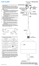
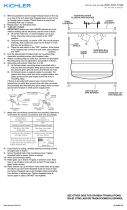
2) Find the appropriate threaded holes on mounting strap.
Assemble mounting screws into threaded holes.
3) Attach mounting strap to outlet box. Mounting strap can be
adjusted to suit position of fixture.
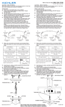
4) Grounding instructions: (See Illus. A or B)
A) On fixtures where mounting strap is provided with a
hole and two raise dimples. Wrap ground wire from
outlet box around green ground screw, and thread into
hole.
B) On fixtures where a cupped washer is provided. Put
ground wire from outlet box under cupped washer and
green ground screw and thread screw into hole in
mounting strap. If fixture is provided with ground wire.
Connect fixture ground wire to outlet box ground wire
with wire connector after following the above steps.
Never connect ground wire to black or white power
supply wires.
5) Make wire connections. Reference chart below for correct
connections and wire accordingly.
6) Carefully push wire connections back into outlet box making
sure all connections remain secure.
7) Push fixture to wall, carefully passing mounting screws
through holes.
8) Screw threaded balls onto mounting screws. Tighten
threaded balls to secure fixture to wall.
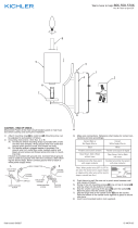
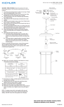
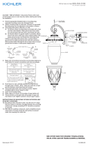
9) Insert recommended bulbs (Not included). Sockets are ac-
cessible through glass door. To open glass door, raise latch
up and pull.
INSTRUCTIONS FOR MOUNTING
FIXTURE OUTDOORS AND/OR IN WET LOCATIONS.
10) Mounting surface should be clean, dry, flat and 1/4” larger
than the canopy on all sides. Any gaps between the mount-
ing surface and canopy exceeding 3/16” should be cor-
rected as required.
11) With silicone caulking compound, caulk completely around
where back of canopy meets the wall surface to prevent
water from seeping into outlet box.
GREEN GROUND
SCREW
CUPPED
WASHER
OUTLET BOX
GROUND
FIXTURE
GROUND
DIMPLES
WIRE CONNECTOR
OUTLET BOX
GROUND
GREEN GROUND
SCREW
FIXTURE
GROUND
A
B
Connect Black or
Red Supply Wire to:
Connect
White Supply Wire to:
Black White
*Parallel cord (round & smooth) *Parallel cord (square & ridged)
Clear, Brown, Gold or Black
without tracer
Clear, Brown, Gold or Black
with tracer
Insulated wire (other than green)
with copper conductor
Insulated wire (other than green)
with silver conductor
*Note: When parallel wires (SPT I & SPT II)
are used. The neutral wire is square shaped
or ridged and the other wire will be round in
shape or smooth (see illus.)
Neutral Wire
CANDLE
SLEEVE
MANGA
DE LA
VELA
GLASS DOOR
PUERTA DE
CRISTAL
LATCH
PESTILLO
WIRE NUT
TUERCAS DE
MARIPOSA
MOUNTING SCREW
TORNILLO
DE MONTAJE
MOUNTING STRAP
CORREA DE MONTAJE
STRAP
MOUNTING SCREW
CORREA DE
TORNILLO
DE MONTAJE
SLOTTED
LOCK-UP KNOB
PERILLA DE
BLOQUEO RANURADA

Date Issued: 04/13/16 IS-49738-US
SEE OTHER SIDE FOR ENGLISH TRANSLATIONS.
VEA EL OTRO LADO DE TRADUCCIONES AL INGLÉS.
We’re here to help 866-558-5706
Hrs: M-F 9am to 5pm EST
1) APAGUE LA ALIMENTACIÓN DE ENERGÍA ELÉCTRICA.
a) IMPORTANTE: Antes de comenzar, NUNCA trate de tra
bajar sin antes desconectar la corriente hasta que el
trabajose termine.
b) Vaya a la caja principal de fusibles o interruptor
automático de su casa. Coloque el interruptor de la cor
riente principal en posición de apagado “OFF”.
c) Desenrosque el (los) fusible(s), o coloque el interruptor
o interruptores automáticos en posición de apagado
“OFF”, que controla(n) la corriente hacia el artefacto o
habitación donde está trabajando.
d) Coloque el interruptor de pared en posición de apagado
“OFF”. Si el artefacto que se va a reemplazar tiene
un interruptor o cadena que se jala, colóquelos en la
posición de apagado “OFF”.
2) Encuentre los agujeros roscados apropiados sobre la correa
de montaje. Ensamble los tornillos de montaje en los
agujeros roscados.
3) Fije la correa de montaje a la caja de salida. La correa de
montaje puede ser ajustada para adaptarse a la posición del
artefacto.
4) Instrucciones para poner a tierra: (Ver ilustraciones A o B)
A) En artefactos donde se suministra la abrazadera de
mon taje con un agujero y dos depresiones onduladas.
Envuelva el conductor de tierra de la caja de salida
alrededor del tornillo de tierra verde y atornille en el
agujero.
B) En artefactos donde se suministra una arandela
cóncava. Fije el conductor de tierra de la caja de salida
debajo de la arandela cóncava y el tornillo de tierra
verde y enrosque en la abrazadera de montaje.
Si se suministra el artefacto con conductor de tierra.
Conecte el conductor de tierra del artefacto al conductor de
tierra de la caja de salida con conector de tierra después
de seguir los pasos anteriores. Nunca conecte el conductor
de tierra a los cables de alimentación eléctrica negros o
blancos.
5) Haga las conexiones de cables. Consulte la gráfica de abajo
con la conexiones correctas y haga el cableado que
corresponde.
6) Empuje cuidadosamente las conexiones de cables dentro
de la caja de salida, cerciorándose de que todas las conex-
iones permanecen seguras.
7) Enrosque las perillas de sujeción en los tornillos de montaje.
Apriete las perillas de sujeción para asegurar el artefacto a
la pared.
8) Enrosque las perillas roscadas en los tornillos de montaje.
Apriete las perillas roscadas para asegurar el artefacto a la
pared.
9) Inserte las bombillas recomendadas (no incluidas). Los
sockets son accesibles a través de puerta de cristal. Para
abrir la puerta de cristal, levantar el cierre y tire.
INSTRUCCIONES PARA MONTAR
EL ARTEFACTO AFUERA Y/O EN LUGARES HÚMEDOS.
10) La superficie de montaje deberá estar limpia, seca, plana
y ser 1/4” más grande que el escudete en todos los lados.
Cualquier espacio libre entre la superficie de montaje y el
escudete que exceda 3/16” deberá ser corregido según sea
requerido.
11) Con masilla de silicona, calafatee completamente alrededor
donde la parte de atrás del escudete se junta con la superfi-
cie de la pared para evitar que el agua se filtre en la caja de
ARANDELA
CONCAVA
TIERRA DE LA
CAJA DE SALIDA
TORNILLO DE TIERRA,
VERDE
DEPRESIONES
TIERRA
ARTEFACTO
CONECTOR DE ALAMBRE
TIERRA DE LA
CAJA DE SALIDA
TORNILLO DE TIERRA,
VERDE
TIERRA
ARTEFACTO
A
B
Conectar el alambre de
suministro negro o rojo al
Conectar el alambre de
suministro blanco al
Negro Blanco
*Cordon paralelo (redondo y liso)
*Cordon paralelo (cuadrado y estriado)
Claro, marrón, amarillio o negro
sin hebra identificadora
Claro, marrón, amarillio o negro
con hebra identificadora
Alambre aislado (diferente del verde)
con conductor de cobre
Alambre aislado (diferente del
verde) con conductor de plata
*Nota: Cuando se utiliza alambre paralelo
(SPT I y SPT II). El alambre neutro es de forma
cuadrada o estriada y el otro alambre será de
forma redonda o lisa. (Vea la ilustracíón).
Hilo Neutral
CANDLE
SLEEVE
MANGA
DE LA
VELA
GLASS DOOR
PUERTA DE
CRISTAL
LATCH
PESTILLO
WIRE NUT
TUERCAS DE
MARIPOSA
MOUNTING SCREW
TORNILLO
DE MONTAJE
MOUNTING STRAP
CORREA DE MONTAJE
STRAP
MOUNTING SCREW
CORREA DE
TORNILLO
DE MONTAJE
SLOTTED
LOCK-UP KNOB
PERILLA DE
BLOQUEO RANURADA
-
 1
1
-
 2
2


Kichler Lighting 49738OZ Manual de usuario
- Tipo
- Manual de usuario
en otros idiomas
- English: Kichler Lighting 49738OZ User manual
Artículos relacionados
-
 Kichler Lighting 44070NI Manual de usuario
-
 Kichler Lighting 3797CH Manual de usuario
-
 Kichler Lighting 43354CH Manual de usuario
-
Kichler Lighting 49686BKL18 Manual de usuario
-
 Kichler Lighting 49689OZ Manual de usuario
-
 Kichler Lighting 43309CLP Manual de usuario
-
 Kichler Lighting 49644OZ Manual de usuario
-
 Kichler Lighting 42910PN Manual de usuario
-
 Kichler Lighting 49846BKT Manual de usuario
-
Kichler Lighting 49669WZC Manual de usuario


