Samson 1352 Parts And Technical Service Manual
- Tipo
- Parts And Technical Service Manual

WASTE OIL COLLECTOR 28 GALLON - 95 L.
RECUPERADOR MOVIL 95 L.
RÉCUPÉRATEUR MOBILE D’HUILE 95 L.
Parts and technical service guide
Guía de servicio técnico y recambios
Guide d’instructions et pièces de rechange
Ref.:
1352
1
R.3/01 1352
Samson Corporation • One Samson Way • N.C. 28778 Swannanoa • Phone: 800.311.1047 • www.samsoncorporation.com
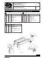
Part list / Lista de componentes para montaje / Pièces de montage
Nº Qty. Part No. Description
11945503 90º Elbow 3/4” MF
21950303 Oil valve 3/4” FF
34942020 Washer
42951116 Wheel Ø160 mm.
52943144 Cotter pin
62940041 Screw
72951208 Wheel Ø77.5 mm.
82942010 Washer
92941010 Nut
E
Nº Ctd. Código Descripción
11945503 Codo 90º 3/4” MH
21950303 Vávula paso aceite
34942020 Arandela
42951116 Rueda fija Ø160 mm.
52943144 Pasador de aletas
62940041 Tornillo hex.
72951208 Rueda giratoria Ø77.5 mm.
82942010 Arandela
92941010 Tuerca hex.
Nº Qté. Référence Description
11945503 Sortie coudée 3/4” MF
21950303 Vanne d’arrêt 3/4” FF
34942020 Rondelle
42951116 Roue fixe Ø160 mm.
52943144 Goupille à double branche DIN94
62940041 Vis
72951208 Roue pivotante Ø77.5 mm.
82942010 Rondelle
92941010 Écrou
F
S
Fig. 1

2
1352 R.3/01
Samson Corporation • One Samson Way • N.C. 28778 Swannanoa • Phone: 800.311.1047 • www.samsoncorporation.com
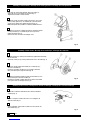
Assembly of Caster wheels / Montaje de las ruedas giratorias / Montage des roues pivotantes
Assembly of fixed wheels / Montaje de las ruedas fijas / Montage des roues fixes
Assembly of the oil valve / Montaje de la válvula de descarga / Montage de la vanne de décharge
- Insert bolt (6) at the wheel bracket; attach the caster (7),
washer (8), and nut (9) below the bracket (Fig. 2).
- Tighten the bolt with a 17MM wrench.
E
- Insertar el tornillo (6) sobre la pletina de fijación; colocar des-
pués la rueda giratoria (7), la arandela (8), y la tuerca hexa-
gonal (9) por debajo de la pletina de fijación (Fig. 2).
- Realizar el apriete de los tornillos con llaves de estrella del nº 17.
S
- Introduire la vis (6) sur la platine de fixation; introduire ensuite
la roue pivotante (7), la rondelle (8) et l’écrou (9) sous la
platine de fixation (Fig. 2).
- Visser les vis avec une clef à oeil multipan nº17.
F
- Slide the washer (3), wheel (4) and washer (3) against the wheel stop
on the axle tube.
- Secure the cotter pin (5) in the provided hole of the axle tube (Fig. 3).
E
- Thread the combined «valve-elbow 90º» with the threaded
coupling (Fig. 4).
E
- Roscar el conjunto «valvula-codo 90º» con el manguito de
salida de aceite (Fig. 4).
S
- Visser l’ensemble «vanne-sortie coudée» avec le manchon de
sortie d’huile (Fig. 4).
F
- Insertar en el tubo lateral la arandela (3), la rueda fija (4) y
otra vez la arandela (3).
- Introducir el pasador de aletas (5) en el agujero lateral del
tubo para evitar que se salga la rueda (Fig. 3).
S
- Introduire la première rondelle (3) dans le tube latéral, la roue
fixe (4) ainsi que la seconde rondelle (3).
- Introduire la goupille à double branche (5) dans le trou latéral
pour que la roue ne s’échappe pas (Fig. 3).
F
Fig. 2
Fig. 3
Fig. 4
-
 1
1
-
 2
2


Samson 1352 Parts And Technical Service Manual
- Tipo
- Parts And Technical Service Manual
En otros idiomas
- français: Samson 1352
- English: Samson 1352
