
Write the model and serial
numbers here:
Model # _________________
Serial # _________________
You can find them on a label on
the inside of the hood.
ESPAÑOL
Para consultar una version en
español de este manual de
instrucciones, visite nuestro sitio de
internet GEAppliances.com.
VENT SYSTEM
Downdraft
49-80777 Rev. 3 03-20 GEA
SAFETY INFORMATION ...........3
USING THE HOOD
Downdraft Vent System ..................5
CARE AND CLEANING
Downdraft Vent System ..................6
INSTALLATION INSTRUCTIONS ..7
TROUBLESHOOTING TIPS ........ 17
LIMITED WARRANTY ............. 18
ACCESSORIES ..................... 19
CONSUMER SUPPORT ............20
UVB30
UVB36
OWNER’S MANUAL &
INSTALLATION
INSTRUCTIONS
GE is a trademark of the General Electric Company. Manufactured under trademark license.

2 49-80777 Rev. 3
THANK YOU FOR MAKING GE APPLIANCES A PART OF YOUR HOME.
Whether you grew up with GE Appliances, or this is your first, we’re happy to have you in the family.
We take pride in the craftsmanship, innovation and design that goes into every GE Appliances
product, and we think you will too. Among other things, registration of your appliance ensures that we
can deliver important product information and warranty details when you need them.
Register your GE appliance now online. Helpful websites and phone numbers are available in the
Consumer Support section of this Owner’s Manual. You may also mail in the pre-printed registration
card included in the packing material.

49-80777 Rev. 3 3
SAFETY INFORMATION
IMPORTANT SAFETY INFORMATION
READ ALL INSTRUCTIONS BEFORE USING
READ AND SAVE THESE INSTRUCTIONS
WARNING
TO REDUCE THE RISK OF FIRE,
ELECTRIC SHOCK OR INJURY TO PERSONS,
OBSERVE THE FOLLOWING:
A. Use this unit only in the manner intended by the
manufacturer. If you have questions, contact the
manufacturer.
B. Before servicing or cleaning unit, switch power off
at service panel and lock the service disconnecting
means to prevent power from being switched
on accidentally. When the service disconnecting
means cannot be locked, securely fasten a
prominent warning device, such as a tag, to the
service panel.
C. Do not use this unit with any solid-state speed
control device.
D. Plug your vent system into a 120-volt grounded
outlet only. Do not remove the round grounding
prong from the plug. If in doubt about the
grounding of the home electrical system, it is your
responsibility and obligation to have an ungrounded
outlet replaced with a properly grounded, three
prong outlet in accordance with the National
Electrical Code. Do not use an extension cord with
this appliance.
CAUTION
FOR GENERAL VENTILATING USE
ONLY. DO NOT USE TO EXHAUST HAZARDOUS
OR EXPLOSIVE MATERIALS AND VAPORS.
WARNING
TO REDUCE THE RISK OF INJURY
TO PERSONS IN THE EVENT OF A RANGE TOP
GREASE FIRE, OBSERVE THE FOLLOWING*:
A. SMOTHER FLAMES with a close-fitting lid, cookie
sheet or metal tray, then turn off the burner. BE
CAREFUL TO PREVENT BURNS. If the flames do
not go out immediately, EVACUATE AND CALL
THE FIRE DEPARTMENT.
B. NEVER PICK UP A FLAMING PAN—You may be
burned.
C. DO NOT USE WATER, including wet dishcloths or
towels—a violent steam explosion will result.
D. Use an extinguisher ONLY if:
1. You know you have a Class ABC extinguisher,
and you already know how to operate it.
2. The fire is small and contained in the area where
it started.
3. The fire department is being called.
4. You can fight the fire with your back to an exit.
* Based on “Kitchen Fire Safety” published by NFPA.

4 49-80777 Rev. 3
SAFETY INFORMATION
IMPORTANT SAFETY INFORMATION
READ ALL INSTRUCTIONS BEFORE USING
READ AND SAVE THESE INSTRUCTIONS
WARNING
TO REDUCE THE RISK OF A
RANGE TOP GREASE FIRE:
A. Never leave surface units unattended at high
settings. Boilovers cause smoking and greasy
spillovers that may ignite. Heat oils slowly on
medium settings.
B. Always turn hood ON when cooking at high heat or
when flambéing food (i.e. Crepes Suzette, Cherries
Jubilee, Peppercorn Beef Flambé).
C. Clean ventilating fans frequently. Grease should not
be allowed to accumulate on fan or filter.
D. Use proper pan size. Always use cookware
appropriate for the size of the surface element.
If You Need Service…
Do not attempt to repair or replace any part of the
vent system unless it is specifically recommended in
this manual. All other servicing should be referred to a
qualified technician.
Be sure electrical power is off before servicing the unit.
It may be necessary to remove the vent system blower
system in order to service components such as the
blower motor or air vent mechanism.
Disconnect power to the cooktop and remove it first.
Reverse the steps in the Install Downdraft Vent section
in the Installation Instructions to remove the blower.
Service parts are available from a GE Appliances
Service and Parts Center.
Make sure all fingers are away from the top of the vent
system when it is lowered.
How to Remove Protective Shipping Film and Packaging Tape
Carefully grasp a corner of the protective shipping film
with your fingers and slowly peel it from the appliance
surface. Do not use any sharp items to remove the film.
Remove all of the film before using the appliance for the
first time.
To assure no damage is done to the finish of the
product, the safest way to remove the adhesive from
packaging tape on new appliances is an application of
a household liquid dishwashing detergent. Apply with a
soft cloth and allow to soak.
NOTE: The adhesive must be removed from all parts. It
cannot be removed if it is baked on.

49-80777 Rev. 3 5
Downdraft Vent System
USING THE VENT SYSTEM: Downdraft Vent System
When Using The Vent System
CAUTION
Be careful when raising or lowering
the vent. Be sure pots, pot handles and other objects are
clear of the vent and cannot be struck or tipped by the
vent being raised.
NOTE: There is a slight trim overhang on each side of
the vent.
Ŷ 7RDYRLGLQMXU\EHVXUHILQJHUVDUHFOHDURIWKHYHQW
cover when it is being lowered.
Ŷ .HHSKDQGVDQGILQJHUVDZD\IURPDOOYHQWSDUWV
IMPORTANT: If the vent is obstructed by an object while
it is being raised or lowered, it will stop. Remove the
obstruction and press the ON/OFF pad again.
To Use The Downdraft System
To raise the downdraft vent, press the ON/OFF pad on
the control. The vent will rise.
Press the Fan Speed HIGHER pad to start the blower.
Adjust the blower by pressing HIGHER or LOWER. The
blower, if left on, will automatically turn off when the vent
is lowered.
NOTE: For most convenient operation, set the blower to
the speed you use most often. The blower will come on
to this speed whenever the unit is raised.
IMPORTANT: The vent can be activated by pressing the
pads on the switch. Do not use excessive force or sharp
objects to activate the switch. Damage could occur and
void the warranty.
Cooking Tips
The high air movement of this vent system can increase
the cooking times for some foods. It may take longer to
reach high cooking temperatures if the vent system is
turned to high right away. Adjust the fan speed for best
cooking results.
For best results when heating oil for deep frying or when
boiling water, use the front surface units or wait until the
water is boiling or the oil is at frying temperatures before
turning on the vent system.
The vent system may not completely capture all the
steam from pans on the front burners.
Controls for 30”
and 36” Models

6 49-80777 Rev. 3
CARE AND CLEANING: Downdraft Vent System
Downdraft Vent System
Painted Or Stainless Steel Surfaces
Do not use a steel wool pad; it will scratch the surface.
To clean the stainless steel surface, use warm, sudsy
water or a stainless steel cleaner or polish. Always wipe
the surface in the direction of the grain. Follow the cleaner
instructions for cleaning the stainless steel surface.
For difficult stains on stainless steel, use a cleaner that
contains lactic acid or citric acid.
To inquire about purchasing cleaning products including
stainless steel appliance cleaner or polish read the
Assistance and Accessories sections at the beginning of
this manual.
Grease Filters
The efficiency of your vent system depends on a clean
filter. Frequency of cleaning depends on the type of
cooking you do. Grease filters should be cleaned at least
once a month. Never operate the vent system without the
filters in place.
To remove: Slip fingers into the vent holes, lift the vent
straight up and pull forward. Grasp the filter tabs, push
down and out of the retainer.
To clean: Soak and then agitate in a hot detergent
solution. Light brushing may be used to remove
embedded soil. Rinse, shake and remove moisture before
replacing. Do not clean the filters in the dishwasher.
With careful handling, the filter will last for years. If
replacement becomes necessary, order the part from
your dealer.
Filter Tabs

49-80777 Rev. 3 7
Installation
Instructions
“If you have questions, call GE Appliances at 800.GE.CARES (800.432.2737)
or visit our website at: GEAppliances.com”
INSTALLATION INSTRUCTIONS
BEFORE YOU BEGIN
Read these instructions completely and
carefully.
•
IMPORTANT — Save these
instructions for local inspector’s use.
•
IMPORTANT — Observe all governing
codes and ordinances.
• Note to Installer – Be sure to leave these
instructions with the Consumer.
• Note to Consumer – Keep these instructions for
future reference.
• Skill level – Installation of this vent hood requires
basic mechanical and electrical skills.
• Proper installation is the responsibility of the
installer.
• Product failure due to improper installation is not
covered under the Warranty.
GROUNDING INSTRUCTIONS
This appliance must be grounded. In the event of
an electrical short circuit, grounding reduces the risk
of electric shock by providing an escape wire for
the electric current. This appliance is equipped with
a cord having a grounding wire with a grounding
plug. The plug must be plugged into an outlet that is
property installed and grounded.
WARNING
Improper grounding can result in a risk of electric
shock.
Consult a qualified electrician if the grounding
instructions are not completely understood, or if
doubt exist as to whether the appliance is properly
grounded.
Do not use an extension cord. If the power supply
cord is too short, have a qualified electrician install
an outlet near the appliance.
If you received a damaged vent system, you should
contact your dealer.
Downdraft Vent Systems
UVB30, UVB36
PARTS SUPPLIED
Open the carton and remove parts package.
Check contents to be sure all pieces are
present.
REMOVE PACKAGING
Remove the shipping materials and the carton;
set carton aside. The carton can be used as a
pad when changing or adjusting vent direction.
TOOLS AND MATERIALS REQUIRED
• Safety glasses
• Large flat-blade screwdriver
• Jigsaw
• Carpenter’s square
• Ductwork to suit the installation
• Level
4 Stabilizing Brackets
With Screws
1 Remote Switch
2 Filters
1 Wire and White
Connector

8 49-80777 Rev. 3
Safety Information
INSTALLATION INSTRUCTIONS
WARNING
TO REDUCE THE RISK OF FIRE,
ELECTRIC SHOCK OR INJURY TO PERSONS,
OBSERVE THE FOLLOWING:
Ɣ,QVWDOODWLRQZRUNDQGHOHFWULFDOZLULQJPXVWEH
done by qualified person(s) in accordance with
all applicable codes and standards, including
fire-rated construction.
Ɣ6XIILFLHQWDLULVQHHGHGIRUSURSHUFRPEXVWLRQDQG
exhausting of gases through the flue (chimney) of
fuel burning equipment to prevent back drafting.
Follow the heating equipment manufacturer’s
guidelines and safety standards such as those
published by the National Fire Protection
Association (NFPA), the American Society for
Heating, Refrigeration and Air Conditioning
Engineers (ASHRAE) and the local code
authorities.
Ɣ:KHQFXWWLQJRUGULOOLQJLQWRZDOORUFHLOLQJGRQRW
damage electrical wiring and other hidden utilities.
Ɣ'XFWHGIDQVPXVWDOZD\VEHYHQWHGWRWKH
outdoors.
CAUTION
TO REDUCE THE RISK OF
FIRE AND TO PROPERLY EXHAUST AIR, BE
SURE TO DUCT AIR OUTDOORS. DO NOT VENT
EXHAUST AIR INTO SPACES WITHIN WALLS OR
CEILINGS OR INTO ATTICS, CRAWL SPACES
OR GARAGES.
WARNING
TO REDUCE THE RISK OF FIRE,
USE ONLY METAL DUCT WORK.
Ɣ:KHQDSSOLFDEOHLQVWDOODQ\PDNHXSUHSODFHPHQW
air system in accordance with local building code
requirements. Visit GEAppliances.com for available
makeup air solutions.
Ɣ39&VHZHUSLSHFDQEHXVHGDVGXFWXQGHU
concrete slab if allowed by local code board.

49-80777 Rev. 3 9
Installation Preparation
INSTALLATION INSTRUCTIONS
POWER SUPPLY
This downdraft vent must be supplied with 120V, 60
Hz. and connected to an individual, properly grounded
branch circuit, protected by a 15- or 20-ampere circuit
breaker or time-delay fuse.
A properly grounded 3-prong receptacle should be
located within reach of the vent’s two-foot power cord.
• Gas Cooktops
If this vent is installed in combination with a GE or
Monogram gas cooktop, it may operate from the same
duplex outlet.
• Electric Cooktops
If this vent is installed in combination with a GE or
Monogram electric cooktop, the vent must operate
from a separate 120V outlet.
Locate the receptacle inside the cabinet on the right side
wall (see illustration). The receptacle cannot be placed
on the back of the cabinet wall where it may interfere
with the downdraft plenum.
The downdraft vent power cord is to be routed beneath
the cooktop and routed away from heat generated by the
cooktop.
Ensure that the cooktop is installed per manufacturer’s
installation instructions.
IMPORTANT
(Please read carefully)
The power cord of this appliance is equipped with
a three-prong (grounding) plug which mates with a
standard three-prong grounding wall receptacle to
minimize the possibility of electric shock. The customer
should have the wall receptacle and circuit checked by
a qualified electrician to make sure the receptacle is
properly grounded and has correct polarity.
• Where a standard two-prong wall receptacle is
encountered, it is the personal responsibility and
obligation of the customer to have it replaced with a
properly grounded three-prong wall receptacle.
Do not, under any circumstances, cut or remove the
third (ground) prong from the power cord.
Do not use an extension cord or adapter plug with this
appliance. Follow National Electrical Code or prevailing
local codes and ordinances.
Location of Rating Label: on front of chassis of vent
system.
Locate the Gas or
Electrical Connection Only
Within the Shaded Area
DO NOT Locate
Gas or Electrical
Connections within
this Area
34" (cutout width) for 36" models
28-1/2" (cutout width) for 30" models
29-1/2"
12"
Electrical
Outlet 12"
Above
Cabinet
Floor

10 49-80777 Rev. 3
Installation Preparation
INSTALLATION INSTRUCTIONS
PRODUCT DIMENSIONS
AB
30” Models 30” 28-5/16”
36” Models 36” 33-15/16”
9.3
.45
1.40
.68
2.24
2.49
32.36
.52
NOTE: The cooktop
overlaps this surface.
NOTE:
This flange
sits on the
countertop.
2.01
23-5/8"

49-80777 Rev. 3 11
INSTALLATION INSTRUCTIONS
Installation Preparation
PREPARING FOR INSTALLATION
• Unpack the cooktop and read the Installation
Instructions to understand the required countertop
cutout dimensions and location in the countertop,
the cooktop spacing to the front edge of the
countertop, and the required clearances to the
cabinets and walls. The vent system required cutout
width is shown on page 4. Confirm there is enough
side to side counter space to meet the required
spacing and clearances for the cooktop.
• Using the illustrations below and taking
measurements of the cooktop to establish dimension
A, confirm there is enough front to back counter
space (dimension B) to fit both the cooktop and the
vent system. Note the cooktop rear edge will overlap
the vent system front surface (refer to Page 5).
• Refer to the Creative Solutions section on page 8 if
more counter space is needed.
• Using the illustrations on pages 5 through 7 and
taking measurements of the vent system and its
exhaust vent location, confirm the clearances
needed within the cabinet, the exhaust vent
direction, and the alignment of the exhaust vent with
the ducting. If needed for clearance or duct hookup
alignment, reposition the location of the cooktop, or
modify the cabinetry, or modify the ducting.
• Confirm the electrical receptacles and gas lines are
correctly located, and relocate if needed.
Side View: Installed Vent Front View: Installed Vent
Cooktop Cooktop
4-1/2” Max
5-1/2”
Max
5-1/2”
Max
B
C
B is the minimum dimension of the
flat portion of countertop that is needed
A
A is the dimension from the screw head on the front surface of
the cooktop base to the rear edge of the cooktop. If you cannot find dimension A
in the cooktop installations instructions, then you must measure it.
Depth of cutout is A + 2 1/8”
Minimum counter depth B = A + C + 2.5"
Dimension C is defined in cooktop Installation Instruction
COOKTOP
1/8” minimum
Front edge
of countertop
Front of cutout
in countertop
Screw head
Front
edge
of
cooktop
Front of cutout
in countertop
Back edge
of cooktop
Back of cut
in countertop
2 1/8”
3/8”
minimum
D
o
w
n
d
r
a
f
t
V
e
n
t

12 49-80777 Rev. 3
Installation Preparation
INSTALLATION INSTRUCTIONS
VENTING OPTIONS
• The downdraft vent is shipped with the
discharge outlet pointing straight down and
can be changed to the left or right side. To
avoid interference problems, the downdraft
vent cannot be vented to the right when
installed with a GE or Monogram gas
cooktop, or with a GE or Monogram non-
induction electric cooktop.
• The blower outlet is sized for 3-1/4” x 10”
and can be transitioned to 6” round.
Side-to-Side Adjustments:
The entire blower mounting plate can be
adjusted 3-1/2” to the left or right. This
will help to align vent discharge to house
ductwork.
Discharge Direction
The blower assembly may be removed and turned 90°
for a left- or right-side discharge.
• A left or right 90° direction adjustment should be
performed before dropping into the countertop
opening.
To change to a left or right discharge:
• Remove the 4 screws holding the blower and the
mounting plate assembly to the downdraft vent.
Retain screws.
• Remove blower assembly; turn it over to access
the 4 nuts holding the blower to the mounting plate.
Remove the nuts.
IMPORTANT: Do not lift motor by the power cable.
• Turn the blower to the left or right discharge
direction and reinstall the 4 nuts.
• Reinstall blower and mounting plate with original
screws.
• To avoid interference problems, the downdraft vent
cannot be vented to the right when installed with
a GE or Monogram gas cooktop, or with a GE or
Monogram non-induction electric cooktop.
Discharge Down
(As Supplied)
Loosen Screws
to Adjust
3-1/2" to
Left or Right
17-1/4"
16-3/8"
10-5/16"
4-1/4"
4-1/4"
4-1/4"
Discharge Down
(As Supplied)
Discharge
Left
Discharge
Right

49-80777 Rev. 3 13
INSTALLATION INSTRUCTIONS
Design Information
CREATIVE SOLUTIONS
• When the kitchen
design calls for an
against-the-wall
installation, move
the base cabinet
forward 3” to 5”.
Filler panels or
complementary
moldings can be
added to exposed
cabinet sides.
• In an island or
peninsula, use
an extra-deep
countertop.
The countertop
overhang at the
front can be
adjusted to meet
setback to cutout
requirements.
• When the cutout
to the front edge of the countertop requirement is
more than 2”, add a bullnose trim to the front edge
of the countertop. Include the trim thickness when
measuring the front edge to cutout requirement. By
adding the trim, the cooktop can be moved forward,
providing additional countertop depth and interior
cabinet space.
• When the distances between the vent and the
inside cabinet side walls are more than 5-1/2” and/
or the inside cabinet back wall is more than 4-1/2”,
false walls should be constructed inside the cabinet
for securing the vent with the stabilizing brackets
(refer to Cutouts and Clearances under Installation
Preparation.)
PREPARING THE COUNTERTOP
Cut out the opening. Measure carefully when cutting
the countertop, making sure the sides of the opening
are parallel and the front and rear cuts are exactly
perpendicular to the sides.
The front of the opening must clear the front support
rail on the cabinet, and the rear of the opening must
clear the rear support of the cabinet.
Chamfer all exposed edges of decorative laminate to
prevent damage from chipping.
Radius corners of cutout and file to ensure smooth
edges and prevent corner cracking.
Rough edges inside corners which have not been
rounded and forced fit can contribute to cracking of the
countertop laminate.
Cover Panel
End
Panel
Countertop
Overhang
per Cooktop
Clearances
Must be
Maintained
Base
Cabinet
Filler Panel
Base Sink
Filler Panel
Maintain Cutout Clearances
to Front Edge as Specified

14 49-80777 Rev. 3
PREPARE FOR DUCTWORK
Determine the best route for ductwork; it can be routed
in a variety of ways depending on the kitchen layout.
IMPORTANT: The downdraft air discharge outlet
IRUWKLVXQLWLV»´[´UHFWDQJXODU3ODQGXFWLQJ
accordingly.
Typical duct arrangement countertop series.
To maximize the ventilation performance of the vent
system:
1. Minimize the duct run length and number of
transitions and elbows.
2. Maintain a constant duct size.
3. Seal all joints with duct tape to prevent any leaks.
4. Do not use any type of flexible ducting.
Design Information
INSTALLATION INSTRUCTIONS
Inside wall
cabinet
Up inside wall to roof or
overhang
Directly to outside
Between floor joists Through cabinet toe space
Peninsula or island
Peninsula
Outside
wall cabinet
NOTE: PVC sewer pipe type PSM 12454-B
Schedule 40 ASTM D1785.
Wall Cap
Concrete
Slab
6" (15 cm)
Dia. PVC
Sewer Pipe
6" (15 cm)
Dia. Metal
Duct
Pack tightly with gravel
or sand completely
around pipe
3-1/4" x 10" Rectangular
to 6" Round Transition
6" (15 cm)
Dia. 90
Metal Elbow
6" (15 cm) Dia.
Metal Duct
16"
(40.6 cm)
Max.
12"
(30 cm)
Min.
6"
(15 cm)
Dia. PVC
Coupling
6" (15 cm) Dia.
PVC Sewer Pipe
Elbow
6" (15 cm) Dia.
PVC Sewer Pipe
Elbow
6" (15 cm)
Dia. PVC
Sewer
Pipe
6"
(15 cm)
Dia.
PVC
Coupling
30'-0" (9.14 m) Max.
Optional duct arrangement under concrete
slab. PVC duct should be used if installing
under a poured concrete slab.
Install ductwork so the piece of duct nearest the
downdraft unit slots INTO the next piece of the duct.
Secure the joints with self-tapping screws and apply
duct tape around the joints to ensure an airtight seal.
Duct Tape
Over Seam and Screw
Screw
Air
Flow

49-80777 Rev. 3 15
INSTALLATION INSTRUCTIONS
Installation Instructions
1
INSTALL DOWNDRAFT VENT
A
Two stabilizing brackets must be installed on
each side of the downdraft vent.
• For right-side or straight-down blower
discharge, fasten the stabilizing brackets at
locations A, B, D and E.
• For left-side blower discharge, fasten the
stabilizing brackets at locations B, C, D and E.
B
Place the downdraft vent into the countertop
cutout so that the back flange of the vent is
sitting on top of the countertop.
C
Secure the screws for the stabilizing brackets
to the cabinet back and side walls.
D
Confirm the vent system is plumb and square
with the cabinetry.
E
Place Cooktop into the countertop cutout. There
should be a 1/8” minimum gap between the
front of the vent trim and the rear of the
cooktop.
F
Connect duct. Use a roof or wall cap (with
damper) that is intended for use with kitchen
hoods and vent systems.
A
C
A
D
C
B
E
4 to 5"
4 to 5"
Top
Brackets
Bottom
Brackets
Bracket
Cabinet Back
Wall
Downdraft Vent
Location A
TOP VIEW
Level
Level

16 49-80777 Rev. 3
Installation Instructions
INSTALLATION INSTRUCTIONS
2
INSTALL REMOTE SWITCH
WARNING
BURN HAZARD
The remote switch must be located so that it can be
operated without reaching over the cooktop. Failure
to do so may result in ignition of clothing which
could cause serious injury or death.
Determine the location for the remote switch.
• Disconnect the remote switch from the harness.
• The remote switch should be located so that
the vertical distance from the floor to the remote
switch is less than 48" and more than 15".
• The remote switch harness is 68" long and should
be installed so that it is not pinched and is away
from moving parts.
• Use the remote switch to determine the exact
center of the hole, confirm there is clearance
behind the hole for the connector and wire to pass
into, and drill a 1/2" diameter hole.
• If the remote switch is not installed on the
countertop, ensure that it is installed in a location
that meets local codes and is easily accessible.
Connect Remote Switch to Remote Harness
• Thread the remote harness through the 1/2"-dia.
hole and attach the harness connector to the
remote connector.
• Remove the paper backing on the remote switch
foam piece and mount the remote switch on the
countertop such that the switch connectors stay
located in the 1/2"-dia. hole.
• Stick adhesive wire clamp near the 1/2"-dia. hole
and attach the loose wire with a wire tie.
Connect Wire Lead to Control Box
• Connect the mating wire ends.
• Place the adhesive wire clamps (provided) near
the mating connector.
• Keep approximately 3"-long wire and attach the
wire to the clamp with a wire tie. This will act as a
strain relief.
1/2"-Dia. Hole
1/2"-Dia.
Hole
Foam Piece With Adhesive
Mounting Surface
Foam Piece With Adhesive
Mounting Surface
Remote Switch
Remote
Switch
Strain Relief
(Adhesive wire clamp
with tie)
Remote
Harness
Control
Box
Remote
Harness
Mating Connectors
Strain Relief
(Adhesive wire
clamp with tie)
3
CONNECT POWER
Plug power cord into properly grounded receptacle.
4
INSTALL FILTERS, CHECK
OPERATION
• Press the ON/OFF pad on the control
to raise the vent.
• Slip fingers into the vent holes. Lift the vent
straight up and pull forward.
• Slide filter into the retainers and close the vent.
• Press the Fan Speed HIGHER pad to start the
blower. Adjust the blower by pressing HIGHER or
LOWER.
• To lower the vent, press the ON/OFF pad.
NOTE: It is not necessary to turn the fan OFF
before lowering the vent. The fan will automatically
turn off when the vent is lowered. When the fan
is not turned off before lowering the vent, it will
automatically come on at the previously set speed
when the vent is fully raised.
IMPORTANT: The vent can be activated by
pressing the pads on the switch. Do not use
excessive force or sharp objects to activate the
switch. Damage could occur and void the warranty.

49-80777 Rev. 3 17
Troubleshooting tips ... Before you call for service
Save time and money! Review the charts on the following pages first and you may not need to call for service.
Problem Possible Cause What To Do
Fan does not work The vent is not fully extended. Press the ON/OFF pad.
Vent does not work The vent is not plugged into an outlet. Plug the vent into a 120V power outlet.
The raise/lower pad did not engage
the lift motor.
Hold down the pad for a couple of seconds to
activate the motor.
The circuit breaker may have tripped. Check the circuit breaker— reset if necessary.
Sufficient makeup (replacement) air is
required for exhausting appliances to
operate to rating.
Check with local building codes, which may
require or strongly advise the use of makeup
air. Visit GEAppliances.com for available
makeup air solutions.
TROUBLESHOOTING TIPS

18 49-80777 Rev. 3
Staple your receipt here. Proof of the original purchase
date is needed to obtain service under the warranty.
GEAppliances.com
All warranty service is provided by our Factory Service Centers, or an authorized Customer Care
®
technician. To schedule
service online, visit us at GEAppliances.com/service, or call GE Appliances at 800.GE.CARES (800.432.2737). Please
have your serial number and your model number available when calling for service.
Servicing your appliance may require the use of the onboard data port for diagnostics. This gives a GE Appliances factory
service technician the ability to quickly diagnose any issues with your appliance and helps GE Appliances improve its
products by providing GE Appliances with information on your appliance. If you do not want your appliance data to be
sent to GE Appliances, please advise your technician not to submit the data to GE Appliances at the time of service.
What GE Appliances will not cover:
Ŷ Service trips to your home to teach you how to use
the product.
Ŷ Improper installation, delivery, or maintenance.
Ŷ Failure of the product if it is abused, misused,
modified, or used for other than the intended purpose
or used commercially.
Ŷ Replacement of house fuses or resetting of circuit
breakers.
Ŷ Damage to the product caused by accident, fire,
floods, or acts of God.
Ŷ Incidental or consequential damage caused by
possible defects with this appliance.
Ŷ Damage caused after delivery.
Ŷ Product not accessible to provide required service.
Ŷ Service to repair or replace light bulbs, except for LED
lamps.
WARRANTY
GE Appliances Warranty
EXCLUSION OF IMPLIED WARRANTIES
Your sole and exclusive remedy is product repair as provided in this Limited Warranty. Any implied warranties,
including the implied warranties of merchantability or fitness for a particular purpose, are limited to one year or
the shortest period allowed by law.
For the period of GE Appliances will replace
One year
From the date
of the original
purchase
Any part of the cooking product which fails due to a defect in materials or workmanship.
During this limited one-year warranty, GE Appliances will provide, free of charge, all labor
and related service costs to replace the defective part.
If you received a damaged downdraft vent system
Immediately contact the dealer (or builder) that sold you the downdraft vent system.
This limited warranty is extended to the original purchaser and any succeeding owner for products purchased for
home use within the USA. If the product is located in an area where service by a GE Appliances Authorized Servicer
is not available, you may be responsible for a trip charge or you may be required to bring the product to an Authorized
GE Appliances Service location for service. In Alaska, the limited warranty excludes the cost of shipping or service
calls to your home.
Some states do not allow the exclusion or limitation of incidental or consequential damages. This limited warranty
gives you specific legal rights, and you may also have other rights which vary from state to state. To know what your
legal rights are, consult your local or state consumer affairs office or your state’s Attorney General.
Warrantor: GE Appliances, a Haier company
Louisville, KY 40225
Extended Warranties: Purchase a GE Appliances extended warranty and learn about special discounts that are
available while your warranty is still in effect. You can purchase it online anytime at
GEAppliances.com/extended-warranty
or call 800.626.2224 during normal business hours. GE Appliances Service will still be there after your warranty expires.

49-80777 Rev. 3 19
ACCESSORIES
Looking For Something More?
GE Appliances offers a variety of accessories to
improve your cooking and maintenance experiences!
Refer to the Consumer Support page for phone numbers
and website information.
The following products and more are available:
Accessories
Parts
Filter UVB30
Filter UVB36
Cleaning Supplies
CitruShine™ Stainless Steel Wipes
CeramaBryte Stainless Steel Appliance Cleaner

20 49-80777 Rev. 3
Consumer Support
CONSUMER SUPPORT
GE Appliances Website
Have a question or need assistance with your appliance? Try the GE Appliances Website 24 hours a day, any day
of the year! You can also shop for more great GE Appliances products and take advantage of all our on-line support
services designed for your convenience. In the US: GEAppliances.com
Register Your Appliance
Register your new appliance on-line at your convenience! Timely product registration will allow for enhanced
communication and prompt service under the terms of your warranty, should the need arise. You may also mail in
the pre-printed registration card included in the packing material. In the US: GEAppliances.com/register
Schedule Service
Expert GE Appliances repair service is only one step away from your door. Get on-line and schedule your service at
your convenience any day of the year. In the US: GEAppliances.com/service
or call 800.432.2737 during normal business hours.
Extended Warranties
Purchase a GE Appliances extended warranty and learn about special discounts that are available while your
warranty is still in effect. You can purchase it on-line anytime. GE Appliances Services will still be there after your
warranty expires. In the US: GEAppliances.com/extended-warranty
or call 800.626.2224 during normal business hours.
Remote Connectivity
For assistance with wireless network connectivity (for models with remote enable),
visit our website at GEAppliances.com/connect or call 800.220.6899 in the US.
Parts and Accessories
Individuals qualified to service their own appliances can have parts or accessories sent directly to their homes
(VISA, MasterCard and Discover cards are accepted). Order on-line today 24 hours every day.
In the US: GEApplianceparts.com or by phone at 877.959.8688 during normal business hours.
Instructions contained in this manual cover procedures to be performed by any user. Other servicing
generally should be referred to qualified service personnel. Caution must be exercised, since improper
servicing may cause unsafe operation.
Contact Us
If you are not satisfied with the service you receive from GE Appliances, contact us on our Website with all the
details including your phone number, or write to:
In the US: General Manager, Customer Relations | GE Appliances, Appliance Park | Louisville, KY 40225
GEAppliances.com/contact

Escriba los números de modelo y de
serie aquí:
Nº de Modelo ____________
Nº de Serie ______________
Estos números también se encuentran en
la Tarjeta de Registro de Propiedad de
Producto enviada en forma separada con
su sistema de ventilación de corriente
descendente y en la etiqueta que se
encuentra en el panel frontal de la unidad.
INFORMACIÓN DE SEGURIDAD ....3
Uso del Sistema de Ventilación
Sistema De Ventilación
De Corriente Descendente ................5
CUIDADO Y LIMPIEZA
Sistema De Ventilación
De Corriente Descendente ................6
INSTRUCCIONES
DE INSTALACIÓN ..................7
CONSEJOS PARA LA SOLUCIÓN
DE PROBLEMAS ................... 17
GARANTÍA LIMITADA .............. 18
ACCESORIOS ........................ 19
SOPORTE PARA
EL CONSUMIDOR ..................20
GE es una marca registrada de General Electric Company. Fabricado bajo licencia de marca.
UVB30
UVB36
MANUAL DEL
PROPIETARIO E
INSTALACIÓN
SISTEMA DE VENTILACIÓN
de corriente descendente
49-80777 Rev. 3 03-20 GEA

2 49-80777 Rev. 3
GRACIAS POR HACER QUE GE APPLIANCES SEA PARTE DE SU HOGAR.
Ya sea que haya crecido usando GE Appliances, o que ésta es su primera vez, nos complace
tenerlo en la familia.
Sentimos orgullo por el nivel de arte, innovación y diseño de cada uno de los electrodomésticos de
GE Appliances, y creemos que usted también. Entre otras cosas, el registro de su electrodoméstico
asegura que podamos entregarle información importante del producto y detalles de la garantía
cuando los necesite.
Registre su electrodoméstico GE ahora a través de Internet. Sitios Web y números telefónicos útiles
están disponibles en la sección de Soporte para el Consumidor de este Manual del Propietario.
También puede enviar una carta en la tarjeta de inscripción preimpresa que se incluye con
el material embalado.

49-80777 Rev. 3 3
INFORMACIÓN DE SEGURIDAD
INFORMACIÓN IMPORTANTE DE SEGURIDAD
LEA TODAS LAS INSTRUCCIONES ANTES DE USAR
LEA Y GUARDE ESTAS INSTRUCCIONES
ADVERTENCIA
PARA REDUCIR EL RIESGO
DE INCENDIO, DESCARGA ELÉCTRICA O LESIONES A
PERSONAS, CUMPLA CON LOS SIGUIENTES PUNTOS:
A. Utilice esta unidad sólo de la manera concebida por el
fabricante. Si tiene alguna pregunta, comuníquese con el
fabricante.
B. Antes de realizar reparaciones o limpiar la unidad,
desconecte la energía del panel de servicio y bloquee los
medios de desconexión para evitar el accionamiento de
la energía de manera accidental. Cuando los medios de
desconexión de servicio no pueden bloquearse, coloque
sobre el panel de servicio un dispositivo de advertencia
bien visible, como una etiqueta.
C. No utilice esta unidad con ningún dispositivo de control
de velocidad de estado sólido.
D. Enchufe el sistema de ventilación en un tomacorriente
con conexión a tierra de 120 voltios únicamente. No retire
la pata redonda de conexión a tierra del enchufe. Si tiene
dudas sobre la conexión a tierra del sistema eléctrico
para hogar, es su responsabilidad y obligación contar
con el reemplazo de un tomacorriente sin conexión a
tierra por un tomacorriente de tres patas correctamente
conectado a tierra, de acuerdo con el Código Nacional
de Electricidad. No use prolongadores con este
electrodoméstico.
PRECAUCIÓN
SÓLO PARA USO DE
VENTILACIÓN GENERAL. NO LO UTILICE PARA
ELIMINAR MATERIALES Y VAPORES PELIGROSOS O
EXPLOSIVOS.
ADVERTENCIA
PARA REDUCIR EL RIESGO DE
LESIONES A PERSONAS EN CASO DE UN INCENDIO
DE GRASA SOBRE UNA ESTUFA, CUMPLA CON LOS
SIGUIENTES PUNTOS*:
A. APAGUE LAS LLAMAS con una tapa que ajuste bien,
una plancha para galletas o una bandeja de metal, y
luego apague el quemador. TENGA MUCHO CUIDADO
A FIN DE EVITAR QUEMADURAS. Si las llamas no
se apagan de inmediato, SALGA DE LA VIVIENDA Y
LLAME AL DEPARTAMENTO DE BOMBEROS.
B. NUNCA LEVANTE UNA SARTÉN EN LLAMAS—
Usted puede quemarse.
C. NO UTILICE AGUA, incluyendo repasadores o toallas
húmedos—se provocará una violenta explosión de vapor.
D. Utilice un extintor SÓLO si:
1. Usted sabe que cuenta con un extintor Clase ABC y
ya sabe cómo utilizarlo.
2. El incendio es pequeño y se contuvo en el área donde
comenzó.
3. Se está llamando al departamento de bomberos.
4. Usted puede combatir el incendio con su espalda
dirigida hacia una salida.
* Basado en “Kitchen Fire Safety” publicado por NFPA.

4 49-80777 Rev. 3
Cómo Retirar la Película Protectora de Envío y la Cinta de Embalaje
Con cuidado tome un extremo de la película protectora
de envío con los dedos y lentamente retire la misma de la
superficie del electrodoméstico. No utilice ningún producto
filoso para retirar la película. Retire toda la película antes de
usar el electrodoméstico por primera vez.
Para asegurar que no haya daños sobre el acabado del
producto, la forma más segura de retirar el adhesivo de la cinta
de embalaje en electrodomésticos nuevos es aplicando un
detergente líquido hogareño para lavar platos. Aplique con una
tela suave y deje que se seque.
NOTA: El adhesivo deberá ser eliminado de todas las partes.
No se puede retirar si se hornea con éste dentro.
INFORMACIÓN DE SEGURIDAD
INFORMACIÓN IMPORTANTE DE SEGURIDAD
LEA TODAS LAS INSTRUCCIONES ANTES DE USAR
LEA Y GUARDE ESTAS INSTRUCCIONES
ADVERTENCIA
PARA REDUCIR EL RIESGO DE
UN INCENDIO DE GRASA SOBRE UNA ESTUFA:
A. Nunca deje unidades de superficie desatendidas en
configuraciones de calor elevadas. Los alimentos que
hierven y se derraman provocan humo y derrames
grasosos que pueden prenderse fuego. Caliente los
aceites lentamente en configuraciones bajas o medias.
B. Siempre encienda el sistema de ventilación cuando
cocine con configuraciones de calor elevadas o cuando
flambee alimentos (por ej., Crepes Suzette, cerezas
Jubilee, carne flambeada a la pimienta en grano).
C. Limpie los ventiladores con frecuencia. No debe
permitirse la acumulación de grasa en el ventilador o en
el filtro.
D. Utilice el tamaño de recipiente adecuado. Siempre utilice
recipientes de cocción apropiados para el tamaño del
elemento de superficie.
Si necesita servicio técnico…
No intente reparar o cambiar ninguna pieza del sistema
de ventilación, a menos que esté específicamente
recomendado en este manual. Cualquier otro servicio debe
realizarlo un técnico calificado.
Asegúrese de cortar la electricidad antes de efectuar
servicio técnico en el aparato.
Puede resultar necesario quitar el sistema de ventilación
para realizar servicio técnico en componentes tales como el
motor del ventilador o el mecanismo de ventilación de aire.
Desconecte la energía que alimenta la estufa y quítela en
primer término. Invierta los pasos de la sección “Cómo
instalar la ventilación descendente” en las Instrucciones de
instalación para quitar el ventilador.
Las piezas para el servicio técnico se encuentran
disponibles en el Centro de Servicio Técnico y Piezas de GE
Appliances.
Cuando baje la ventilación, mantenga los dedos alejados de
la parte superior del sistema de ventilación.

49-80777 Rev. 3 5
Sistema De Ventilación De Corriente Descendente
Uso del Sistema de Ventilación: Sistema de ventilación de corriente descendente
Cuando Utilice el Sistema de Ventilación
PRECAUCIÓN
Tenga cuidado al levantar o bajar
la ventilación. Asegúrese de que las cacero las, las manijas
de las cacerolas y otros objetos se encuentren alejados de la
ventilación y que no se golpeen o vuelquen cuando se la eleve.
NOTA: Hay una pequeña saliente en cada lado de la ventilación.
Ŷ 3DUDHYLWDUOHVLRQHVPDQWHQJDORVGHGRVDOHMDGRVGHOD
tapa de la ventilación cuando se la baje.
Ŷ 0DQWHQJDODVPDQRV\ORVGHGRVDOHMDGRVGHWRGDVODV
piezas de la ventilación.
IMPORTANTE: Si la ventilación queda obstruida con un objeto
mientras se la sube o baja, ésta se detendrá. Quite la obstrucción
y presione de nuevo el botón ON/OFF (encendido/apagado).
Sistema De Ventilación De Corriente Descendente
Para levantar la ventilación de corriente descendente, presione
el botón ON/OFF (encendido/apagado) del control. La
ventilación se elevará.
Presione el botón HIGHER (más alta) de la velocidad del
ventilador para accionarlo. Ajuste la velocidad del ventilador
presionando HIGHER (más alta) o LOWER (más baja). Si se
lo deja encendido, el ventilador se apagará automáticamente
cuando se baje la ventilación.
NOTA: Para un funcionamiento más conveniente, configure el
ventilador a la velocidad que utilice más a menudo. El ventilador
se accionará a esta velocidad cuando la unidad se eleve.
IMPORTANTE: La ventilación puede activarse presionando los
botones del interruptor. No ejerza una fuerza excesiva ni utilice
objetos afilados para activar el interruptor. Pueden producirse
daños que invalidan la garantía.
Consejos De Cocción
El elevado movimiento de aire de este sistema de ventilación
puede aumentar los tiempos de cocción de algunos alimentos.
Puede tomar más tiempo alcanzar temperaturas de cocción
elevadas si se acciona la ventilación en la configuración “alta”
desde el comienzo. Para mejores resultados de cocción,
ajuste la velocidad del ventilador.
Para mejores resultados cuando caliente aceite para freír o
cuando hierva agua, utilice las unidades de superficie frontales
o espere a que el agua esté hirviendo o a que el aceite
se encuentre a temperatura de fritura antes de accionar el
sistema de ventilación.
Es posible que el sistema de ventilación no capture por
completo todo el vapor proveniente de las ollas de los
quemadores frontales.
Controles para los
modelos
de 30” y 36”

6 49-80777 Rev. 3
CUIDADO Y LIMPIEZA: Sistema de ventilación de corriente descendente
Sistema De Ventilación De Corriente Descendente
Superficies Pintadas O De Acero Inoxidable
No utilice almohadillas de acero porque rayan la superficie.
Para limpiar la superficie de acero inoxidable, utilice agua tibia
jabonosa o un limpiador o lustrador para acero inoxidable.
Siempre limpie la superficie en dirección de la veta. Siga las
instrucciones del producto para limpiar la superficie de acero
inoxidable.
En caso de haber manchas difíciles de quitar sobre el acero
inoxidable, use un limpiador que contenga ácido láctico o ácido
cítrico.
Para realizar consultas sobre la adquisición de productos,
incluyendo limpiadores o pulidores para electrodomésticos de
acero inoxidable, lea las secciones de Asistencia y Accesorios,
en el comienzo de este manual.
Filtros De Grasa
La eficiencia del sistema de ventilación depende de la
limpieza del filtro. La frecuencia de limpieza depende del tipo
de cocción que realice. Los filtros de grasa deben limpiarse
por lo menos una vez por mes. Nunca opere el sistema de
ventilación si los filtros no están colocados correctamente.
Para quitar: Deslice los dedos en los orificios de ventilación
y levante la cubierta hacia arriba y empújela hacia adelante.
Tome las lengüetas del filtro, presione hacia abajo y quite de
la traba.
Para limpiar: Sumerja y luego agite en una solución de
detergente caliente. Puede utilizarse un cepillo suave para
quitar la suciedad muy adherida. Enjuague, agite y quite la
humedad antes de volver a colocar. No lave los filtros en el
lavavajillas.
Con una manipulación cuidadosa, el filtro durará muchos años.
Si necesita reemplazarlo, solicite el repuesto a su vendedor.
Lengüetas del filtro

49-80777 Rev. 3 7
¿Preguntas? Llame al 800.GE.CARES (800.432.2737) o visite nuestro sitio Web en: GEAppliances.com
Instrucciones
de instalación
INSTRUCCIONES DE INSTALACIÓN
Sistemas de Ventilación
de Aire Descendente
UVB30, UVB36
ANTES DE COMENZAR
Lea estas instrucciones por completo y con
detenimiento.
•
IMPORTANTE — Guarde estas instrucciones
para el uso de inspectores locales.
•
IMPORTANTE — Cumpla con todos los códigos
y ordenanzas vigentes.
• Nota al instalador – Asegúrese de dejar estas
instrucciones con el consumidor.
• Nota al consumidor – Conserve estas
instrucciones para referencias futuras.
• Nivel de capacidad – La Instalación de este
electrodoméstico debe ser realizada por un instalador
calificado o por un electricista.
• El instalador tiene la responsabilidad de efectuar una
instalación adecuada.
• La Garantía no cubre las fallas del producto debido a
una instalación incorrecta.
INSTRUCCIONES PARA DESCARGA
A TIERRA
Este electrodoméstico debe estar conectado a tierra.
En caso de que se produzca un cortocircuito, la
conexión a tierra reduce el riesgo de descarga eléctrica,
brindando un cable de escape de la corriente eléctrica.
Este electrodoméstico está equipado con un cable de
corriente que posee un cable de conexión a tierra con
un enchufe a tierra. El enchufe se deberá colocar en un
tomacorriente instalado y conectado a tierra de forma
adecuada.
ADVERTENCIA
Una conexión a tierra inadecuada puede producir riesgos
de descargas eléctricas.
Consulte a un electricista calificado en caso de
que las instrucciones de conexión a tierra no se
entiendan completamente, o si tiene dudas sobre si
el electrodoméstico está conectado a tierra de forma
apropiada.
No use un prolongador. Si el cable de corriente es
demasiado corto, solicite a un electricista calificado que
instale un tomacorriente cerca del electrodoméstico.
Si el sistema de ventilación que recibió está dañado, se
deberá comunicar con su vendedor minorista.
PIEZAS PROVISTAS
Abra el cartón y retire el paquete de piezas. Controle los
contenidos a fin de asegurar que todas las piezas estén
presentes.
QUITE EL EMPAQUE
Retire los materiales embalados y el cartón; deje a un
lado el cartón. El cartón puede ser usado como base al
cambiar o ajustar la dirección de la ventilación.
HERRAMIENTAS Y MATERIALES
REQUERIDOS
• Gafas de seguridad
• Destornillador con cabeza plana largo
• Sierra de vaivén
• Regla de carpintero
• Tubería adecuada para la instalación
• Nivel
4 Soportes de
Estabilización con
Tornillos
1 Interruptor Remoto
2 Filtros
1 Cable y un
Conector Blanco

8 49-80777 Rev. 3
Información de Seguridad
INSTRUCCIONES DE INSTALACIÓN
ADVERTENCIA
PARA REDUCIR EL
RIESGO DE INCENDIO, DESCARGA ELÉCTRICA
O LESIONES A PERSONAS, CUMPLA CON LOS
SIGUIENTES PUNTOS:
• El trabajo de instalación y el cableado eléctrico
deben ser realizados por una persona(s) calificada
de acuerdo con todos los códigos y estándares
aplicables, incluyendo construcciones resistentes al
fuego.
• Es necesario contar con suficiente cantidad de aire
para una combustión y salida de gases adecuadas
a través del conducto (chimenea) del equipo de
consumo de combustible, a fin de evitar ráfagas de
aire. Siga las pautas del fabricante del equipo de
calefacción y los estándares de seguridad, tales como
aquellos publicados por la Asociación Nacional de
Protección contra Incendios (National Fire Protection
Association, NFPA), la Sociedad Estadounidense
para la Calefacción (American Society for Heating),
los Ingenieros de Refrigeración y Acondicionadores
de Aire (Refrigeration and Air Conditioning Engineers,
ASHRAE) y las autoridades de los códigos locales.
• Al cortar o perforar una pared o un cielorraso, no dañe
el cableado eléctrico y de otros servicios ocultos.
• Los ventiladores con conducto siempre deben contar
con ventilación hacia el exterior.
PRECAUCIÓN
PARA REDUCIR EL
RIESGO DE INCENDIO Y PARA ELIMINAR
EL AIRE DE ESCAPE CORRECTAMENTE,
ASEGÚRESE DE DIRIGIR EL AIRE DEL
CONDUCTO HACIA EL EXTERIOR. NO VENTILE
EL AIRE DE ESCAPE EN ESPACIOS DENTRO
DE PAREDES O CIELORRASOS O EN ÁTICOS,
HUECOS SANITARIOS O GARAJES.
ADVERTENCIA
A FIN DE REDUCIR
EL RIESGO DE INCENDIOS, USE SÓLO
CONDUCTOS DE METAL.
• Cuando corresponda, instale un sistema de reposición
(reemplazo) de aire de acuerdo con los requisitos
del código local de construcción. Para acceder a
soluciones relacionadas con la reposición de aire,
visite GEAppliances.com.
• La tubería de cloaca de PVC puede ser usada como
conducto bajo una losa de concreto, si esto lo permite
la junta del código local.

49-80777 Rev. 3 9
Preparación para la instalación
INSTRUCCIONES DE INSTALACIÓN
SUMINISTRO DE ENERGÍA
Esta ventilación de aire descendente debe ser provista con
120V, 60 Hz, y estar conectada a un circuito de empalmes
individual correctamente conectado a tierra, protegido por un
disyuntor o fusible de retardo de 15 o 20 amp.
Un receptáculo de 3 clavijas correctamente conectado a
tierra debe estar dentro del alcance del cable de corriente
de dos pies de la ventilación.
• Superficies de Cocción a Gas
Si esta ventilación es instalada junto con una superficie
de cocción a gas de GE o Monogram, puede funcionar
desde el mismo tomacorriente doble.
• Superficies de Cocción Eléctricas
Si esta ventilación es instalada junto con una superficie
de cocción eléctrica de GE o Monogram, la ventilación
debe funcionar desde un tomacorriente de 120V aparte.
Ubique el receptáculo dentro del gabinete en la pared lateral
derecha (vea la ilustración). El receptáculo no puede ser
colocado en la parte trasera de la pared del gabinete, donde
puede interferir con el plenum de aire descendente.
El cable de corriente de la ventilación de aire descendente
se debe conducir por debajo de la superficie de cocción y
alejado del calor generado por esta última.
Asegúrese de que la superficie de cocción sea instalada de
acuerdo con las instrucciones de instalación del fabricante.
IMPORTANTE
(Tenga a bien leer cuidadosamente)
El cable de corriente de este electrodoméstico cuenta
con un enchufe de 3 clavijas (con cable a tierra) que se
conecta a un receptáculo de pared con conexión a tierra
de tres clavijas para minimizar la posibilidad de descargas
eléctricas. El cliente deberá solicitar a un electricista
calificado que controle el receptáculo de pared y el circuito,
a fin de asegurar que el receptáculo esté adecuadamente
conectado a tierra y que cuente con la polaridad correcta.
• En caso de contar con un receptáculo de pared de dos
clavijas, es responsabilidad y obligación del cliente
reemplazarlo por un tomacorriente de pared de tres
clavijas correctamente conectado a tierra.
Nunca, bajo ninguna circunstancia, corte o elimine el
tercer cable (tierra) del cable de corriente.
No use prolongadores ni adaptadores con este
electrodoméstico. Siga el Código Nacional de Electricidad o
los códigos y ordenanzas locales establecidos.
Ubicación de la Etiqueta de Clasificación en el frente del
chasis del sistema de ventilación.
Ubique la Conexión de Gas
o Eléctrica Únicamente
dentro del Área Sombreada
NO Ubique las
Conexiones de
Gas o Eléctricas
dentro de esta
Área
34” (ancho del recorte) para modelos de 36”
28” ½” (ancho del recorte) para modelos de 30”
29-1/2"
12"
Toma-
corriente
Eléctrico de
12” sobre
el Piso del
Gabinete

10 49-80777 Rev. 3
Preparación para la instalación
INSTRUCCIONES DE INSTALACIÓN
DIMENSIONES DEL PRODUCTO
23-5/8"
AB
30" Modelos 30" 28-5/16"
36" Modelos 36" 33-15/16"
9.3
.45
1.40
.68
2.24
2.49
32.36
.52
NOTA: La superficie
de cocción se superpone
con esta superficie.
NOTA:
Esta pestaña
se apoya
sobre la
mesada.
2.01

49-80777 Rev. 3 11
INSTRUCCIONES DE INSTALACIÓN
Preparación para la instalación
PREPARANDOSE PARA LA INSTALACIÓN
• Desembale la superficie de cocción y lea las Instrucciones
de Instalación a fin de entender las dimensiones
necesarias requeridas para la mesada y su ubicación,
el espacio entre la superficie de cocción y el extremo
frontal de la mesada, y los despejes necesarios con los
gabinetes y paredes. El ancho del espacio requerido
para el sistema de ventilación se muestra en la página 4.
Confirme que haya suficiente espacio entre un lado y otro
para contar con los espacios y despejes necesarios para
la superficie de cocción.
• Utilizando las siguientes ilustraciones y tomando las
medidas de la superficie de cocción para establecer
la dimensión A, confirme que haya suficiente espacio
entre el frente y la parte trasera (dimensión B) para
colocar tanto la superficie de cocción como el sistema
de ventilación. Observe que el extremo trasero de la
superficie de cocción se superpondrá con la superficie
frontal del sistema de ventilación (consulte la Página 5).
• De ser necesario más espacio para la mesada, consulte
la sección de Soluciones Creativas en la página 8.
• Utilizando las ilustraciones en las páginas 5 y 7 y
tomando las medidas del sistema de ventilación y la
ubicación de la salida de la ventilación, confirme los
espacios necesarios dentro del gabinete, la dirección
del escape de la ventilación, y la alineación del escape
de la ventilación con el conducto. De ser necesario
para el despeje o la alineación del enlace del conducto,
reposicione la ubicación de la superficie de cocción, o
modifique la ubicación de los muebles, o la tubería.
• Confirme que los receptáculos eléctricos y las tuberías de
gas estén correctamente ubicadas, y vuelva a ubicar las
mismas de ser necesario.
B
C
B es la dimensión mínima de la parte
plana de la mesada que es necesaria
A
A es la dimensión desde la cabeza del tornillo en la superficie frontal de la base de la superficie
de cocción hasta el extremo trasero de la superficie de cocción. Si no puede encontrar la dimensión
A en las instrucciones de instalación de la superficie de cocción, entonces deberá medirla.
La profundidad del recorte es A + 2 1/8”
La profundidad mínima de la mesada es B = A + C + 2.5”
La dimensión C está definida en las Instrucciones
de Instalación de la superficie de cocción
SUPERFICIE DE COCCIÓN
Mínimo de 1/8”
Extremo frontal
de la mesada
Frente del recorte
en la mesada
Cabeza del tornillo
Extremo
frontal de
la superficie
de cocción
Frente del recorte
en la mesada
Extremo trasero de
la superficie de cocción
Parte Trasera
del Recorte
en la mesada
2 1/8”
Mínimo
de 3/8”
V
e
n
t
i
l
a
c
i
ó
n
d
e
A
i
r
e
D
e
s
c
e
n
d
e
n
t
e
Vista Lateral: Ventilación Instalada Vista Frontal: Ventilación Instalada
Superficie de cocción Superficie de cocción
Máx. de 4 1/2"
Máx.
de 5 1/2"
Máx.
de 5 1/2"

12 49-80777 Rev. 3
Preparación para la instalación
INSTRUCCIONES DE INSTALACIÓN
OPCIONES DE VENTILACIÓN
• La ventilación de aire hacia abajo es enviada
con el tomacorriente de descarga apuntando
hacia abajo y puede ser modificada hacia
el lado izquierdo o derecho. A fin de evitar
problemas de interferencias, la descarga de
corriente descendente no podrá ser ventilada
hacia la derecha, cuando se instale con una
superficie de cocción a gas de GE o Monogram,
o con una superficie de cocción eléctrica que no
sea de inducción de GE o Monogram.
• El tomacorriente del calefactor está ajustado
para la medida de 3 1/4” x 10” y puede ser
modificado hasta 6”.
Ajustes de Lado a Lado:
Toda la placa de montaje del calefactor puede ser
ajustada a 3 ½” hacia la izquierda o derecha. Esto
ayudará a alinear la descarga de la ventilación al
conducto del hogar.
Dirección de la Descarga
El ensamble del calefactor puede ser retirado y girado 90º
para una descarga hacia la izquierda o la derecha.
• Un ajuste de 90º hacia la izquierda o derecha debe ser
realizado antes de caer en la abertura de la mesada.
Para cambiar a una descarga hacia la izquierda o
derecha:
• Retire los 4 tornillos que sostienen el calefactor y el
ensamble de la placa de montaje hasta la ventilación de
aire hacia abajo. Tornillos de retención.
• Retire el ensamble del calefactor; dé vuelta el mismo para
acceder a las 4 tuercas que sostienen el calefactor sobre
la placa de montaje. Retire las tuercas.
IMPORTANTE: No levante el motor desde el cable de
corriente.
• Gire el calefactor hacia la dirección de descarga izquierda
o derecha y vuelva a instalar las 4 tuercas.
• Vuelva a instalar el calefactor y la placa de montaje con
los tornillos originales.
• A fin de evitar problemas de interferencias, la descarga
de corriente descendente no podrá ser ventilada hacia la
derecha, cuando se instale con una superficie de cocción
a gas de GE o Monogram, o con una superficie de cocción
eléctrica que no sea de inducción de GE o Monogram.
Descarga Hacia Abajo
(Según lo Provisto)
Tornillos Flojos para
Ajustar 3 ½” a la
Izquierda o Derecha
17-1/4"
16-3/8"
10-5/16"
4-1/4"
4-1/4"
4-1/4"
Descarga Hacia Abajo
(Según lo Provisto)
Descarga Hacia
la Izquierda
Descarga Hacia
la Derecha

49-80777 Rev. 3 13
INSTRUCCIONES DE INSTALACIÓN
Instrucciones de instalación
SOLUCIONES CREATIVAS
• Cuando el diseño de
la cocina requiera
una instalación contra
la pared, mueva el
gabinete de la base
hacia delante entre 3”
y 5”. Los paneles de
relleno o las molduras
complementarias
pueden ser agregadas
a los costados
expuestos de los
gabinetes.
• En una isla o
península, use
una mesada extra
profunda. La parte
saliente del frente
de la mesada puede
ser ajustada para
cumplir con los
requisitos entre el
mueble lindero y el
espacio de recorte.
• Cuando el espacio de recorte requerido hasta el extremo
frontal de la mesada sea superior a 2”, agregue un borde
redondeado al extremo frontal de la mesada. Incluya el
ancho del borde al medir el espacio requerido desde el
extremo frontal hasta el recorte. Al agregar el borde, la
superficie de cocción puede ser movida hacia delante,
brindando profundidad adicional a la mesada y al espacio
interno de los gabinetes.
• Cuando las distancias entre la ventilación y las paredes
laterales internas de los gabinetes sean superiores a 5
½” y/o la pared trasera del gabinete interno sea superior
a 4 ½”, se deberán construir paredes falsas dentro del
gabinete para asegurar la ventilación con los soportes
de estabilización (consulte los Recortes y Despejes en
Preparación de la Instalación).
PREPARACIÓN DE LA MESADA
Recorte la abertura. Mida cuidadosamente al recortar la
mesada, asegurándose de que los costados de la abertura
sean paralelos y que los recortes frontal y trasero sean
exactamente perpendiculares a los costados.
El frente de la abertura debe despejar el riel del soporte
frontal del gabinete, y la parte trasera de la abertura debe
despejar el soporte trasero del gabinete.
Bisele todos los extremos expuestos del laminado decorativo
a fin de evitar daños por astillado.
Haga un radio en las esquinas del recorte y lime para
asegurar que los extremos queden parejos y para
prevenir la fisura de los bordes.
Los extremos ásperos dentro de las esquinas que no fueron
redondeadas y un ajuste forzado pueden contribuir a la
formación de fisuras del laminado de la mesada.
Gabinete
de la Base
Panel
de Relleno
Lavabo
de la Base
Panel
de Relleno
Mantenga los Espacios de
Despeje hasta el Extremo Frontal
de Acuerdo con lo Especificado
Panel de Cobertura
Panel
Final
Se Debe Mantener
la Parte Saliente
de la Mesada para
Contar con los
Despejes de la
Superficie de Cocción
Ventilación de
Aire Descendente
A
gregue un Borde
Redondeado y otra
Moldura para Incrementar
la Profundidad de la
Mesada y para Mantener
el Espacio Requerido
desde el Extremo
Frontal hasta el Despeje.
Borde

14 49-80777 Rev. 3
PREPARACIÓN DEL CONDUCTO
Determine el mejor recorrido para el conducto; el mismo
puede ser conducido de diferentes formas dependiendo del
esquema de la cocina.
IMPORTANTE: La salida de la descarga de aire
descendente para esta unidad es rectangular, y con una
medida de 3 ¼” x 10”. Planifique el recorrido de forma
consecuente.
Serie de mesadas con distribución típica de tuberías.
A fin de maximizar el rendimiento de la ventilación del
sistema de ventilación:
1. Minimice la longitud del conducto y el número de
transiciones y codos.
2. Mantenga un tamaño de conducto constante.
3. Selle todas las juntas con cinta para conductos a fin de
evitar pérdidas.
4. No utilice conductos flexibles de ningún tipo.
Preparación para la instalación
INSTRUCCIONES DE INSTALACIÓN
Pared interna
del gabinete
Pared interna hacia arriba hasta
el techo o la parte saliente
Directamente hacia el exterior
Entre vigas del piso A través del espacio de las
patas del gabinete
Península o una
isla
Península
Pared externa
del gabinete
Arreglo opcional del conducto bajo una losa de
concreto. Se deberá usar un conducto de PVC si
se instalará bajo una losa de concreto.
Instale la tubería de modo que el trozo de conducto más
cercano a la unidad de ventilación de aire descendente
encaje DENTRO DE la siguiente pieza del conducto.
Asegure las uniones con tornillos autorroscantes y coloque
cinta para conductos alrededor de las uniones, a fin de sellar
la salida de aire.
NOTA: Tubería de cloaca de PVC tipo
PSM 12454-B Norma 40 ASTM D1785.
Tapa de Pared
Losa de
Concreto
Tubería de
Cloaca
de PVC
de6″(15 cm)
de Diám.
Conducto
Metálico de
6” (15 cm)
de Diám.
Embale de forma bien ajustada
con grava o arena completamente
alrededor de la tubería.
Transición Rectangular
de 3 ¼” x 10” a Circular de 6”
Codo Metálico de
6” (15 cm) de
Diám. y 90º
Conducto Metálico
de 6” (15 cm) de Diám.
Máx. de
16″(40.6 cm)
Mín. de
12″(30 cm)
Acople de
PVC de
6″(15 cm)
de Diám.
Codo para Tubería
de Cloaca de
6” (15 cm) de Diám.
Codo para Tubería de
Cloaca de 6″(15 cm) de Diám.
Tubería
de Cloaca
de PVC
de 6″(15 cm)
de Diám.
Acople de
PVC de
6″(15 cm)
de Diám.
Máx. de 30′-0″(9.14 m)
Cinta para Conducto
sobre la Unión y el Tornillo
Tornillo
Flujo
de Aire

49-80777 Rev. 3 15
1
INSTALE LA VENTILACIÓN DE AIRE
DESCENDENTE
A
Dos soportes de estabilización deben ser instalados
sobre cada lado de la ventilación de aire
descendente.
• Para una descarga del calentador hacia el lado
derecho o directamente hacia abajo, ajuste los
soportes de estabilización en las ubicaciones A,
B, D y E.
• Para una descarga del calentador hacia el lado
izquierdo, ajuste los soportes de estabilización en
las ubicaciones B, C, D y E.
B
Coloque la ventilación de aire descendente en el
recorte de la mesada, de modo que la pestaña
trasera de la ventilación se apoye sobre la mesada.
C
Asegure los tornillos de los soportes de
estabilización a las paredes trasera y lateral del
gabinete.
D
Confirme que el sistema de ventilación esté
centrado y en escuadra con los gabinetes.
E
Coloque la superficie de cocción en el recorte
de la mesada. Debe haber un espacio mínimo
de 1/8” entre el frente del borde de ventilación
y la parte trasera de la superficie de cocción.
F
Conecte el conducto. Use un techo o tapa de
pared (con regulador) para uso con campanas
de cocina y sistemas de ventilación.
A
C
A
D
C
B
E
4 to 5”
4 to 5”
Soportes
Superior
Soportes
Inferior
Soporte
Pared Trasera
del Gabinete
Ventilación de Aire Descendente
Ubicación A
VISTA SUPERIOR
Nivel
Nivel
INSTRUCCIONES DE INSTALACIÓN
Instrucciones de instalación

16 49-80777 Rev. 3
Preparación para la instalación
INSTRUCCIONES DE INSTALACIÓN
2
INSTALE EL INTERRUPTOR
REMOTO
ADVERTENCIA
RIESGO DE INCENDIO
El interruptor remoto debe estar ubicado de modo que
pueda ser utilizado sin llegar a la superficie de cocción.
Si esto no se hace, se podrá incendiar la ropa, lo cual
puede ocasionar lesiones graves o la muerte.
Determine la ubicación del interruptor remoto.
• Desconecte el interruptor remoto del arnés.
• El interruptor remoto debe ser ubicado de modo que
la distancia vertical entre el piso y el interruptor remoto
sea inferior a 48” y de más de 15”.
• El arnés del interruptor remoto posee una longitud de
68” y debe ser instalado de modo que no sufra presión
y que esté alejado de las partes móviles.
• Use el interruptor remoto para determinar el centro
exacto del agujero, confirme que haya espacio detrás
del agujero para que el conector y el cable puedan
pasar, y perfore un agujero de ½” de diámetro.
• Si el interruptor remoto no es instalado en la mesada,
asegúrese de que sea instalado en una ubicación que
cumpla con los códigos locales y que sea de fácil acceso.
Conecte el Interruptor Remoto al Arnés Remoto
• Pase el arnés remoto a través del agujero de ½” de
diámetro y ajuste el conector del arnés al conector
remoto.
• Retire el papel que cubre el trozo de gomaespuma del
interruptor remoto y monte el interruptor remoto en la
mesada, de modo que los conectores con interruptor
permanezcan ubicados en el agujero de ½” de diámetro.
• Adhiera la clavija del cable adhesivo cerca del agujero
de ½” de diámetro y ajuste el cable suelto con un nudo
en el cable.
Conecte el Cable a la Caja de Control
• Conecte los extremos de los cables emparejados.
• Coloque las clavijas de los cables adhesivos
(provistos) cerca del conector de emparejamiento.
• Cuente con aproximadamente un cable de 3” de
longitud y adhiera el cable a la clavija con un nudo de
cable. Esto actuará como un amortiguador de refuerzo.
Agujero de 1 ½” de Diám.
Agujero de
1 ½” de Diám.
Trozo de Gomaespuma
con Superficie de
Montaje Adhesiva
Trozo de Gomaespuma
con Superficie de Montaje
Adhesiva
Interruptor Remoto
Interruptor
Remoto
Amortiguador de
Refuerzo (Clavija
adhesiva para cable
con cinta)
Arnés
Remoto
Control
Box
Arnés Remoto
Conectores Emparejados
Amortiguador de
Refuerzo (Clavija
adhesiva para
cable con nudo)
Caja
de Control
3
CONECTE LA CORRIENTE
Enchufe el cable de corriente en un receptáculo
correctamente conectado a tierra.
4
INSTALE LOS FILTROS, CONTROLE
EL FUNCIONAMIENTO
• Presione la tecla ON/OFF (Encender/ Apagar) en el
control para incrementar la ventilación.
• Deslice los dedos en los agujeros de la ventilación.
Levante la ventilación hacia arriba y empuje hacia delante.
• Deslice el filtro sobre los tensores y cierre la ventilación.
• Presione la tecla Fan Speed HIGHER (Velocidad
del Ventilador MÁS ALTA) para activar el calefactor.
Ajuste el calefactor presionando HIGHER (Más Alto) o
LOWER (Más Bajo).
• Para bajar el nivel de ventilación, presione la tecla ON/
OFF (Encender/ Apagar).
NOTA: No es necesario apagar el ventilador antes de
bajar el nivel de ventilación. El ventilador se apagará de
forma automática cuando la ventilación se baje. Cuando
el ventilador no es apagado antes de bajar el nivel
de ventilación, el mismo irá de forma automática a la
velocidad configurada previamente cuando la ventilación
se incremente hasta el máximo.
IMPORTANTE: La ventilación puede ser activada
presionando las teclas del interruptor. No use fuerza
excesiva ni objetos puntiagudos para activar el interruptor.
Se podrán producir daños que anulen la garantía.

49-80777 Rev. 3 17
CONSEJOS PARA LA SOLUCIÓN DE PROBLEMAS
Consejos para la Solución de Problemas... Antes de solicitar el servicio técnico
Ahorre tiempo y dinero! Primero revise los cuadros que aparecen en las siguientes páginas y es posible que no necesite solicitar
reparaciones.
Problema Causa Posible Qué hacer
El ventilador no
funciona
El ventilador no está extendido por completo. Presione el botón Encender/Apagar (ON/OFF).
La ventilación no
funciona
La ventilación no está enchufada en un
tomacorriente.
Enchufe la ventilación en un tomacorriente de 120V.
El botón subir/bajar no accionó el motor de
elevación.
Sostenga el botón durante unos segundos para activar
el motor.
El interruptor de circuitos puede haber
saltado.
Verifique el interruptor de circuitos y reconfigúrelo si
fuera necesario.
Se requiere suficiente reposición (reemplazo)
de aire para que los artefactos con salida
de aire funcionen de acuerdo con sus
calificaciones energéticas.
Controle los códigos locales de construcción, que
podrán requerir o aconsejar enfáticamente el uso de
reposición de aire. Para acceder a soluciones de aire
disponibles, visite GEAppliances.com.

18 49-80777 Rev. 3
Abroche su recibo aquí. Para acceder al servicio técnico de acuerdo con
la garantía deberá contar con la prueba de la fecha original de compra.
GEAppliances.com
Todo el servicio de garantía es provisto por nuestros Centros de Servicio de Fabricación, o un técnico autorizado de Customer Care®.
Para programar una visita del servicio técnico a través de Internet, visítenos en www.geappliances.com/service_and_support/, o
llame al 800.GE.CARES (800.432.2737). Cuando llame para solicitar el servicio, tenga los números de serie y modelo disponibles.
Para realizar el servicio técnico de su electrodoméstico, se podrá requerir el uso de datos del puerto de abordaje para su diagnóstico.
Esto da al técnico del servicio de fábrica de GE Appliances la habilidad de diagnosticar de forma rápida cualquier problema con
su electrodoméstico, y de ayudar a GE Appliances a mejorar sus productos al brindarle a GE Appliances la información sobre su
electrodoméstico. Si no desea que los datos de su electrodoméstico sean enviados a GE Appliances, solicitamos que le indique a su
técnico no entregar los datos a GE Appliances en el momento del servicio.
Qué no cubrirá GE Appliances:
Ŷ Viajes del técnico del servicio a su hogar para enseñarle
sobre cómo usar el producto.
Ŷ ,QVWDODFLyQHQWUHJDRPDQWHQLPLHQWRLQDGHFXDGRV
Ŷ )DOODVGHOSURGXFWRHQFDVRGHDEXVRPDOXVRPRGLILFDFLyQ
o uso para propósitos diferentes al original o uso comercial.
Ŷ 5HHPSOD]RGHIXVLEOHVGHODFDVDRUHLQLFLRGHGLV\XQWRUHV
Ŷ 'DxRVRFDVLRQDGRVVREUHHOSURGXFWRSRUDFFLGHQWH
incendio, inundaciones o catástrofes naturales.
Ŷ 'DxRVLQFLGHQWDOHVRFRQVHFXHQWHVFDXVDGRVSRUSRVLEOHV
defectos sobre este producto.
Ŷ 'DxRVVREUHHODFDEDGRWDOHVFRPRy[LGRVREUHOD
superficie, deslustres o manchas pequeñas no informadas
dentro de las 48 horas luego de la entrega.
Ŷ 'DxRFDXVDGRGHVSXpVGHODHQWUHJD
Ŷ 3URGXFWRQRDFFHVLEOHSDUDEULQGDUHOVHUYLFLRUHTXHULGR
Ŷ 0DUFDVRPDQFKDVLQFOX\HQGRPDQFKDVGHy[LGRVREUH
la superficie) que pueden ser eliminadas siguiendo las
instrucciones de limpieza.
Ŷ 6ROLFLWHHOVHUYLFLRWpFQLFRSDUDUHSDUDURUHHPSOD]DUODV
lámparas, excepto las lámparas LED.
GARANTÍA
Garantía de GE Appliances
EXCLUSIÓN DE GARANTÍAS IMPLÍCITAS
Su única y exclusiva alternativa es la reparación del producto, como se indica en la Garantía Limitada. Las
garantías implícitas, incluyendo garantías implícitas de comerciabilidad o conveniencia sobre un propósito
particular, se limitan a un año o al período más corto permitido por la ley.
Por el Período de GE Appliances reemplazará
Un Año
Desde la fecha de la
compra original
Cualquier pieza del producto de cocción que falle debido a un defecto en los materiales o la
fabricación. Durante esta garantía limitada de un año, GE Appliances también proveerá, sin costo,
todo el trabajo y costos del servicio relacionados con el reemplazo de la pieza defectuosa.
Si usted recibió un sistema de ventilación de corriente descendente averiado
Comuníquese de inmediato con el vendedor (o constructor) que le vendió el sistema de ventilación de corriente descendente.
Esta garantía limitada se extiende al comprador original y a cualquier propietario posterior de los productos
comprados para uso doméstico dentro de EE. UU. Si el producto está en un área donde no se encuentra disponible
un Proveedor Autorizado del Servicio Técnico de GE Appliances, usted será responsable por el costo de un viaje o se
podrá requerir que traiga el producto a una ubicación del Servicio Técnico de GE Appliances autorizado para recibir el
servicio. En Alaska, la garantía limitada excluye el costo de envío o visitas de servicio a su domicilio. Algunos estados
no permiten la exclusión o limitación de daños fortuitos o consecuentes. Esta garantía limitada le otorga derechos
legales específicos, y usted también podría tener otros derechos que varían de estado a estado. Para conocer cuáles
son sus derechos legales, consulte a la oficina de asuntos del consumidor local o estatal o al Fiscal de su estado.
Garante: GE Appliances, a Haier company
Louisville, KY 40225
Garantías Extendidas: Adquiera una garantía extendida de GE Appliances y conozca los descuentos especiales que
están disponibles mientras su garantía aún está vigente. Puede acceder a la misma a través de Internet en cualquier
momento en
GEAppliances.com/extended-warranty
o llamando al 800.626.2224 durante el horario comercial. Los Servicios para los GE Appliances aún estarán
disponibles cuando su garantía caduque.

49-80777 Rev. 3 19
ACCESORIOS
¿Busca Algo Más?
GE Appliances ofrece una variedad de accesorios para
mejorar sus experiencias de cocción y mantenimiento!
Para acceder a números telefónicos e información de sitios
Web, consulte la página de Soporte para el Consumidor.
Estos y otros productos están disponibles:
Accesorios
Piezas
Filtro UVB30
Filtro UVB36
Suministros de Limpieza
Limpiadores de Acero Inoxidable CitriShine™
Limpiador de Electrodomésticos de Acero Inoxidable
CeramaBryte

20 49-80777 Rev. 3
Soporte para el Consumidor
SOPORTE PARA EL CONSUMIDOR
Sitio Web de GE Appliances
¿Desea realizar una consulta o necesita ayuda con su electrodoméstico? ¡Intente a través del Sitio Web de GE Appliances las
24 horas del día, cualquier día del año! Usted también puede comprar más electrodomésticos maravillosos de GE Appliances y
aprovechar todos nuestros servicios de soporte a través de Internet, diseñados para su conveniencia.
En EE.UU.: GEAppliances.com
Registre su Electrodoméstico
¡Registre su electrodoméstico nuevo a través de Internet, según su conveniencia! Un registro puntual de su producto permitirá
una mejor comunicación y un servicio más puntual de acuerdo con los términos de su garantía, en caso de surgir la necesidad.
También puede enviar una carta en la tarjeta de inscripción preimpresa que se incluye con el material embalado.
En EE.UU.: GEAppliances.com/register
Servicio Programado
El servicio de reparación de expertos de GE Appliances está a sólo un paso de su puerta. Conéctese a través de Internet y programe
su servicio a su conveniencia cualquier día del año. En EE.UU.: GEAppliances.com/service
o comuníquese al 800.432.2737 durante el horario de atención comercial.
Garantías Extendidas
Adquiera una garantía extendida de GE Appliances y conozca los descuentos especiales que están disponibles mientras su
garantía aún está vigente. La puede adquirir en cualquier momento a través de Internet. Los servicios de GE Appliances aún
estarán allí cuando su garantía caduque.
En EE.UU.: GEAppliances.com/extended-warranty
o comuníquese al 800.626.2224 durante el horario de atención comercial.
Conectividad Remota
Para solicitar asistencia para la conectividad de red inalámbrica (para modelos con acceso remoto),
visite nuestro sitio web en GEAppliances.com/connect o comuníquese al 800.220.6899 en EE.UU.
Piezas y Accesorios
Aquellos individuos calificados para realizar el servicio técnico de sus propios electrodomésticos podrán solicitar el envío de
piezas o accesorios directamente a sus hogares (se aceptan las tarjetas VISA, MasterCard y Discover). Ordene hoy a través de
Internet durante las 24 horas, todos los días. En EE.UU.: GEApplianceparts.com o de forma telefónica al 877.959.8688 durante
el horario de atención comercial.
Las instrucciones que figuran en este manual cubren los procedimientos que serán realizados por cualquier usuario.
Otros servicios técnicos generalmente deben ser derivados a personal calificado del servicio. Se deberá tener cuidado,
ya que una reparación indebida podrá hacer que el funcionamiento no sea seguro.
Contáctenos
Si no se encuentra satisfecho con el servicio que recibió de GE Appliances, comuníquese con nosotros a través de nuestro sitio
Web con todos los detalles, incluyendo su número telefónico, o escriba a:
En EE.UU.: General Manager, Customer Relations | GE Appliances, Appliance Park | Louisville, KY 40225
GEAppliances.com/contact
-
 1
1
-
 2
2
-
 3
3
-
 4
4
-
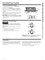 5
5
-
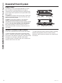 6
6
-
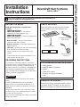 7
7
-
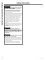 8
8
-
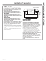 9
9
-
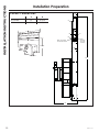 10
10
-
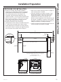 11
11
-
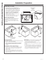 12
12
-
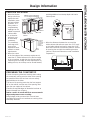 13
13
-
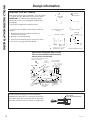 14
14
-
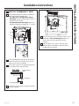 15
15
-
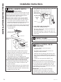 16
16
-
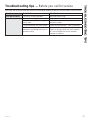 17
17
-
 18
18
-
 19
19
-
 20
20
-
 21
21
-
 22
22
-
 23
23
-
 24
24
-
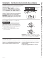 25
25
-
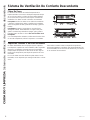 26
26
-
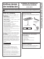 27
27
-
 28
28
-
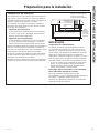 29
29
-
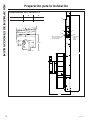 30
30
-
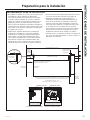 31
31
-
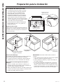 32
32
-
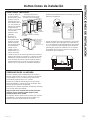 33
33
-
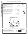 34
34
-
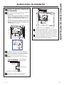 35
35
-
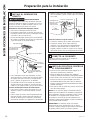 36
36
-
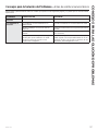 37
37
-
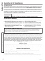 38
38
-
 39
39
-
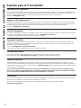 40
40


