Swisher LS722B El manual del propietario
- Categoría
- Partidores de troncos
- Tipo
- El manual del propietario

Read and follow all Safety
Precautions and Instructions
before operating this
equipment.
LOG
SPLITTER
1602 CORPORATE DRIVE, WARRENSBURG, MISSOURI 64093 PHONE 660-747-8183
FAX 660-747-8650
Manufacturing quality lawn care equipment since 1945
Safety
Assembly
Operation
Service and Adjustment
Repair Parts
Made In The
USA
swisherinc.com
12380
Rev. 08-217
Model LS6522B Shown
OWNER’S
MANUAL
MODEL NO.
LS6522B
STARTING SERIAL #:
L108-224015
LS722B
STARTING SERIAL #:
L108-224015
LS728B
STARTING SERIAL #:
L108-224015
LS87522B
STARTING SERIAL #:
L108-224015
LS10528B
STARTING SERIAL #:
L108-224015
LS12534B
STARTING SERIAL #:
L108-224015
LS12534B12V
STARTING SERIAL #:
L108-224015
IMPORTANT

2
In the event you have a claim under this warranty, you must return the product to an authorized service dealer.
All transportation charges, damage, or loss incurred during transportation of parts submitted for replacement or
repair under this warranty shall be borne by the purchaser. Should you have any questions concerning this
warranty, please contact us toll-free at 1-800-222-8183. The model number, serial number, date of purchase,
and the name of the authorized Swisher dealer from whom you purchased the splitter will be needed before any
warranty claim can be processed.
THIS WARRANTY DOES NOT APPLY TO ANY INCIDENTAL OR CONSEQUENTIAL
DAMAGES AND ANY IMPLIED WARRANTIES ARE LIMITED TO THE SAME TIME PERIODS
STATED HEREIN FOR ALL EXPRESSED WARRANTIES. Some states do not allow the limitation of
consequential damages or limitations on how long an implied warranty may last, so the above limitations or
exclusions may not apply to you. This warranty gives you specific legal rights and you may have other rights,
which vary from state-to-state. This is a limited warranty as defined by the Magnuson-Moss Act of 1975.
LIMITED WARRANTY
The manufacturer’s warranty to the original consumer purchaser is: This product is free from defects in
materials and workmanship for a period of two (2) year from the date of purchase by the original consumer
purchaser. We will repair or replace, at our discretion, parts found to be defective due to materials or
workmanship. This warranty is subject to the following limitations and exclusions:
TABLE OF CONTENTS
WARRANTY………………....….2
SAFETY..……………………….3-4
TOWING..….……..……………..5
OPERATION……………………6-8
MAINTENANCE.…………………….8
DECALS…..………….……………….9
PARTS BREAKDOWN…………….10-13
SPECIFICATIONS..…………………15
1) Engine Warranty All engines utilized on our products have a separate warranty extended
to them by the individual engine manufacturer. Any engine service
difficulty is the responsibility of the engine manufacturer and in no
way is Swisher Mower Co., Inc. or its agents responsible for the engine
warranty. The Briggs & Stratton Engine Service Hot-Line is 1-800-
233-3723. The Tecumseh Engine Service Hot-Line is 1-800-558-5402.
2) Commercial Use The warranty period for any product used for commercial or rental is
limited to ninety (90) days from the date of original purchase.
3) Limitation This warranty applies only to products which have been properly
assembled, adjusted, and operated in accordance with the instructions
contained within this manual. This warranty does not apply to any
product of Swisher Mower Co., Inc., that has been subject to alteration,
misuse, abuse, improper assembly or installation, shipping damage, or
to normal wear of product.
4) Exclusions Excluded from this warranty are normal wear, normal adjustments, and
normal maintenance. The pump, valve, and cylinder each carry separate
manufacture’s warranties. The valve and cylinder both carry a one (1) year
limited warranty. The pump carries a two (2) year limited warranty.

SAFETY PRECAUTIONS
WARNING:
The engine exhaust from this product contains chemicals known to the state of California
to cause cancer, birth defects or other reproductive harm.
DANGER: Your log splitter was built to be operated according to the rules for safe operation in this
manual. As with any type of power equipment, carelessness or error on the part of the operator can result
in serious injury. If you violate any of these rules, you may cause serious injury to yourself or others.
•
Read and understand the manual. Learn to operate this equipment in a safe manner. Familiarize
yourself with all of the controls in a safe environment before starting to work with this machine.
•
DO NOT under any circumstances alter this log splitter. This equipment was designed and
engineered in accordance with operating instructions. Altering this equipment, or using this
equipment in such a way as to circumvent its design capabilities and capacities, could result in
serious injury or fatality and WILL VOID THE WARRANTY.
•
Allow ONLY responsible adults who have read this manual to operate this machine. NEVER
allow children to operate this machine.
•
NEVER operate or allow someone to operate this equipment while under the influence of
alcohol, drugs or medication. Being coherent is essential for safety.
• ALWAYS use outdoors with adequate ventilation. DON’T run the engine in an enclosed area.
Exhaust gases contain carbon monoxide. This odorless gas can be deadly when inhaled.
•
NEVER use splitter for any other purpose than splitting wood. Any other use can result in
injury. Your splitter is a precision piece of power equipment, not a toy. Therefore, exercise
extreme caution at all times.
• ONLY a single operator is to load and operate the log splitter. KEEP all others, including pets
and children, a minimum of 20 feet away from your work area. More accidents occur when
more than one person operates the log splitter than any other time.
• ALWAYS wear protective gear such as safety goggles, protective hearing device, steel-toed
shoes, and tight-fitting gloves without drawstrings or loose cuffs.
•
NEVER wear loose clothing or jewelry that can be caught by moving parts of the splitter and
pull you into it. Keep hair away from moving parts.
• NEVER operate your splitter on wet, muddy, or icy surfaces. KEEP work area clean of split
wood. Safe footing is essential in preventing accidents.
• ONLY operate splitter on level ground with wheels blocked, not on the side of a hill. It could
tip, or rolling logs, poor footing, etc. could cause an accident.
This Safety Alert Symbol indicates important messages in this manual.
When you see this symbol, carefully read the message that follows and be
alert to the possibility of personal injury.
Read this manual completely. This machine can amputate hands, feet, and throw objects.
Failure to observe the following safety instructions could result in serious injury or death.
3

4
•
NEVER operate your splitter near a flame or spark. Hydraulic oil and gasoline are flammable and can
explode.
•
NEVER fill gas tank while the engine is hot or running. Allow the engine to cool before refueling.
•
This unit is equipped with an internal combustion engine and should not be used on or near any
unimproved forest-covered, brush-covered or grass-covered land unless the engine’s exhaust system is
equipped with a spark arrester meeting applicable local or state laws (if any). If a spark arrester is used it
should be maintained in effective working order by the operator.
-NOTE-
In the state of California, the above is required by law (Section 442 of the California Public Resources Code).
Other states may have similar laws. Federal laws apply on federal lands. A spark arrester muffler (optional by
manufacturer) is available at your nearest engine dealer. Check legal requirements in your area.
• ONLY use your hands to operate the control lever. NEVER use foot, knee, rope or any extension device.
• Split ONLY one log at a time. NEVER attempt to split two logs on top of each other.
• NEVER place hands or feet between log and splitting wedge or between log and ram during forward or
reverse stroke. ALWAYS keep fingers clear of splits that open in log during splitting operation.
• DO NOT straddle or reach across the splitting area while operating the splitter.
• DO NOT step over splitter when the engine is running. You may trip or accidentally activate the splitting
wedge. Walk around to get to the other side.
•
NEVER attempt to load splitter while splitting wedge is in motion. When loading log splitter, place hands
on the sides of the log, not the ends.
•
NEVER attempt to split woods across the grain. Wood may burst or fly out of your splitter and result in
serious injury.
• NEVER leave your splitter unattended with the engine running. Shut off the engine if you are leaving
your splitter, even for a short period of time. Someone could accidentally activate the ram and be injured.
• Both ends of the log should be cut as squarely as possible to prevent the log from sliding out of the splitter
during operation. Log length should be kept to 24” or less.
•
NEVER operate your splitter while it is attached to the tow vehicle.
•
BEFORE towing, be certain that the splitter is securely attached to the towing vehicle and that the support
leg, beam and cylinder are secured in there respective towing positions.
•
NEVER allow persons to ride on splitter. DO NOT carry any cargo or wood on your splitter. It may fall
off and cause an accident.
•
DO NOT loosen or remove any hydraulic fitting, line or reservoir cap while your splitter or engine is
running.
• Fluid escaping from a very small hole can almost be invisible. DO NOT check for leaks with your hand.
See maintenance section for instructions.
IF injured by escaping fluid, see a doctor at once. Serious
infection or reaction can develop if proper medical treatment is not administered immediately.
•
DO NOT operate your splitter in poor mechanical condition or when it is need of repair.
•
ALWAYS disconnect the spark plug wire and place the wire where it cannot contact the spark plug, to
prevent accidental starting the engine when setting up, transporting, adjusting or repairing.

TOWING SAFETY
• Do not allow persons to ride on splitter. Do not carry any cargo or wood on your
splitter. It may fall off and endanger vehicles that are following you.
• Be sure support leg is in the travel position and coupling secure. This must also
be retracted so not to interfere while towing. Retract support leg by removing
pin, pivoting up, and replacing pin.
• Never exceed 45 MPH while towing your splitter. Be extra cautious when
traveling over rough terrain, especially over railroad tracks.
• Always be careful while backing your splitter. You
could jackknife your log
splitter if not careful.
• Before using splitter, disconnect it from tow vehicle. A log could easily be
pushed forward into the vehicle.
• See tire and wheel specifications for PSI while towing.
• Be aware of the extra length of splitter while turning, parking, crossing
intersections, and in all driving situations.
•
OPERATION INSTRUCTIONS
POSI-LOCK COUPLER
ADJUST COUPLER LOCKING PRESSURE ON BALL BEFORE USE. PLACE HANDLE IN LOCKED
POSITION WITH BALL IN COUPLER. TIGHTEN LOCKNUT AGAINST TENSION SPRING SO THAT
COUPLER IS NOT LOOSE ON BALL. CORRECT ADJUSTMENT WILL ALLOW HANDLE TO BE
RELEASED WITH MODERATE PRESSURE APPLIED TO HANDLE.
TO OPEN, PULL UP ON COUPLER HANDLE AND ROTATE FORWARD. PLACE COUPLER ON BALL
WHEN BALL IS COMPLETELY NESTED IN BALL SOCKET, ROTATE COUPLER HANDLE
BACKWARD UNTIL HANDLE IS IN LOCKED POSITION.
AFTER TOWING FOR 50 MILES, CHECK COUPLER FOR TIGHTNESS ON BALL. ALWAYS CHECK
TIGHTNESS BEFORE TOWING. BE SURE COUPLER HANDLE IS IN LOCKED POSITION.
WARNING:
NEVER EXCEED WEIGHT CAPACITY AND ALWAYS USE SAFETY CHAINS. ALWAYS USE
CORRECT BALL SIZE, MAKING SURE BALL IS COMPLETELY INSERTED INTO COUPLER. LOCK
COUPLER HANDLE SECURELY BEFORE TOWING. ALWAYS CHECK FOR DAMAGES AND
REPLACE IF DAMAGED. AVOID SHARP TURNS AND STEEP VERTICAL ANGLES WHEN TOWING.
5

6
ASSEMBLY
This log splitter has been partially assembled at the factory. Refer to the drawings and part lists should it become
necessary to disassemble the unit for repair or replacement of parts.
Inspect all components for damage. If you believe you have a damaged part please contact customer service
immediately at 1-800-222-8183.
WARNING: Exercise extreme caution, as parts are very heavy. Sufficient persons or mechanical handling
equipment should be used.
Refer to uncrating and assembly instructions for assembly procedures.
OPERATION
INTENDED USE: This log splitter is intended and designed to only split wood. NEVER use for any other
purposes. Doing so can cause injury or VOID THE WARRANTY.
IMPORTANT: This unit is shipped with oil but without gasoline in the engine. After assembly, see separate
Engine Manual for proper fuel and oil recommendations.
WARNING: DO NOT START OR RUN THE LOG SPLITTER WITHOUT OIL IN THE ENGINE AND
HYDRAULIC RESERVOIR.
FILLING THE HYDRAULIC RESERVOIR
Fill the hydraulic reservoir to the top mark on the dipstick with Dexron III / Mercon III automatic transmission
fluid, a 10W AW hydraulic fluid or Pro-Mix AW-32 Hydraulic oil. After the hydraulic reservoir and the engine
crankcase are filled correctly with their respective oils, start the engine. Remember to set the throttle and turn on
the fuel shut-off valve. The hydraulic pump should prime itself. With the engine running, move the hydraulic
valve lever toward the wedge. This will cause the cylinder to extend and expel air. When the cylinder is fully
extended, retract it. Repeat this procedure several times. (An erratic movement of the cylinder and wedge indicates
that there is air in the system). Once the cylinder has a smooth and constant speed indicating that all air has been
expelled, shut the system off and refill the reservoir until the fluid is in the safe operating range as specified by the
marks on the dipstick.
START UP
WARNING:
DO NOT START OR RUN THE LOG SPLITTER WITHOUT OIL IN THE ENGINE
AND HYDRAULIC RESERVOIR.
See separate Engine Manual for fuel and oil recommendations. If applicable your log splitter has come equipped
with a fuel shut-off valve for towing purposes.
Before starting engine make sure crankcase is filled correctly with oil and the proper fuel has been used. The
engine will only start when the throttle lever and fuel shut-off valve if applicable are turned to their ON positions.
STARTING INSTRUCTIONS
1. Move throttle control to “FAST.”
2. Set Choke to on position (if applicable) or push primer bulb three (3) times. NOTE: Do not use primer or
choke to restart a warm engine after a short shutdown.
3. Grasp rope handle and pull out slowly until resistance it felt. Then pull rapidly with a full arm stroke.
NOTE: If engine fails to start after three (3) pulls, repeat steps 1 and 2.
4. When Engine starts, set choke to off position (if applicable) leave throttle control at “FAST.” The throttle
must be set in the fast position for maximum performance.
5. To stop engine, move throttle lever to “SLOW” for a few seconds then to “STOP.”

7
COLD WEATHER START UP
The Cold Weather Clutch enables the engine to be started without having to pull through cold,
thickened hydraulic fluid. Simply pull the handle out into locked position. Start engine, let it warm up,
and release Cold Weather Clutch. After starting, assure that the lever has reengaged.
SPLITTER OPERATION
1. Set up the log splitter in a clear, level area and block the wheels. The suction port on the tank should
always be on the lower side of the log splitter.
2. Place a log on the beam, against the foot plate. Make sure the log is securely on the foot plate and up
against the beam.
3. Depress the valve lever so that the cylinder will drive the push block into the log. Extend the cylinder
until the log splits or to the end of its stroke. If the log has not completely split after the cylinder has
reached the end of its extension, retract the cylinder. NOTE: Leaving the valve in the “actuate” position
at the end of the stroke may damage the pump. Always use extra care when splitting logs with ends that
are not square.
NOTE:
To extend the life of the hydraulic cylinder, avoid “BOTTOMING OUT” the cylinder.
TOWING SAFETY
This unit should not be towed on any street, highway, or public road without checking the existing federal, local,
and state laws. Any licensing or modifications such as taillights, etc., need to comply with existing federal, local,
or state vehicle requirements is the sole responsibility of the purchaser. Obey all regulations when towing on
public roads and highways. See also
SAFETY PRECAUTIONS.
Turn the fuel shut-off valve if applicable OFF to prevent flooding of the engine while traveling.
Be careful when backing up. You can easily jack-knife your splitter.
TOWING AT NIGHT
The requirements for taillights are based on States regulations. Some states allow towing at night as
long as the towed equipment does not visibly impair the tow vehicle taillights. This is based on a state,
to state requirements. The customer is responsible for meeting the states requirements.
If a “Statement of Origin” is required in your state, see your local dealer to receive one.
HYDRAULIC SAFETY
The hydraulic system on your splitter requires careful inspection along with the mechanical parts. Be sure to
replace any frayed, kinked, cracked or otherwise damaged hydraulic components. Just because it isn’t leaking
today doesn’t mean that it will not fail tomorrow.
Fluid escaping from a very small hole can almost be invisible. Do not check for leaks with your hand. Escaping
fluid under pressure can have sufficient force to penetrate skin causing serious personal injury or even death.
Leaks can be detected by passing a piece of cardboard or wood over the suspected leak and looking for
discoloration. IF injured by escaping fluid, see a doctor a
t once. Serious infection or reaction can develop if
proper medical treatment is not administered immediately.
Should it become necessary to loosen or remove any hydraulic fittings, lines or reservoir cap, be sure to relieve all
pressure by shutting of the engine and moving the control handle back and forth several times.
NEVER remove the cap from the hydraulic tank or reservoir while the unit is running. Hot oil under pressure
could result in serious injury. See also
SAFETY PRECAUTIONS.
The pressure relief valve on your splitter is preset at the factory. DO NOT adjust the valve. Only a qualified
technician should perform this adjustment.

8
MAINTENANCE AND STORAGE
WARNING:
DISCONNECT THE SPARK PLUG BEFORE PERFORMING ANY MAINTENANCE.
Consult the operating and maintenance instructions of the engine manufacturer for engine care.
Always check the oil level of the hydraulic reservoir before operation. Operating without an adequate oil
supply will cause severe damage to the pump. Change the hydraulic fluid in the reservoir after every 100 hours of
operation. Change the hydraulic filter after every 50 hours of operation (use only a 10 micron hydraulic filter).
Periodically check that all nuts, bolts, screws, clamps and fittings are tight and secure.
To keep your splitter in top working condition perform all recommended maintenance procedures before you use
your splitter.
If the wedge becomes dull or nicked a grinder or sharpening tool can be used to sharpen it.
Completely drain the fuel tank prior to storage. Always store gasoline in an approved, tightly sealed container. Store
container in a dry, cool place with adequate ventilation. Keep fuel away from areas where fumes could contact open
flame, pilot light or sparks.
Be aware of the environment when disposing of used petroleum products. Please dispose of used hydraulic
fluid, engine oil and any by products from the maintenance of your splitter at approved recycling centers.
Should it become necessary to disassemble the unit for repair or replacement of parts, refer to the drawings and parts
list on the following pages. Exercise extreme caution, as some parts are very heavy and will require sufficient
persons or mechanical handling equipment.
Your Swisher Log Splitter has been produced with components designed specifically to this machine. Although
standard springs, hardware and ect may look similar to parts used on other machinery, they may in some cases
be made of a different construction and/or materials. All replacement parts must meet manufacturer’s
specifications.
The operation of any splitter can produce foreign objects to be thrown into the
eyes, resulting in severe eye damage. Always wear certified safety glasses or
wide-vision safety goggles over spectacles before staring any splitting machine
and while operating such a machine.
The operation of any splitter produces sound waves that are damaging to the
human ear. Ear protection is recommended.

9
11427 – DANGER DECAL
12492 – OPERATOR INSTRUCTION
DECAL
OD16 – FUEL SHUT OFF DECAL 12493 – COLD WEATHER DECAL
SAFETY DECALS
Replace decals immediately if damaged.
12549 – DO NOT EXCEED 45 MPH
DECAL
12494 – HYDRAULIC FILL PLUG
12532 – ADD HYDRAULIC OIL
BEFORE OPERATING

10
ASSEMBLY DETAIL
LS6522B & LS12534B MODELS
Model LS722B Shown

11
SERVICE PARTS
Please have Model and Serial Numbers ready when ordering parts.
Color cannot be guaranteed upon service parts.
ITEM NUMBER DESCRIPTION PART NUMBER
1 Motor Base/Hydraulic Tank 12350TK
2 36" Suction Hose 12362
3 #12 Hose Clamp LS5001
4 Filter Head LS1112
5 Filter Element LS1113
6 Return Line Fitting 7329
7 3/4" NPT Vent Cap w/Dipstick 12379
8 Bearing Seal 2203S
9 Tapered Bearing 2203B
10 Tire & Wheel 7296
11 Washer 3/4ID X 1 1/4OD 10GA NB184
12 Castle Nut 2203CN
13 Cotter Pin NB633
14 Wheel Dust Cover 2203DC
15 High Pressure Hose 48" 15149
16 Bolt 3/8-16 X 1 1/2 GR 5 NB107
17 Washer 3/8 SAE NB272
18 Idler Bushing 6037
20 Nut 3/8-16 Nyloc NB182
21 Bolt 3/8-16 X 2 1/2 GR 5 NB619
22 Idler Arm 6041TK
23 Idler Pulley B527
24 Nut 3/8-16 2-Way Lock NB280
25 Clutch Lever 11226TK
26 Clutch Lever Cap 2077
27 Wire Link For Idler Arm BRS6H
28 Idler Tension Spring - Bent Leg 4422
29 Bolt Spade 5/16-18 X 12 10636YZ
30 Nut 5/16-18 Nyloc NB181
31 Return Hose 72" 12363
32 #16 Hose Clamp LS4999
33 Bolt - 1/2-13 X 6 HCC GR5 ZP NB151
34 Nut - Jam Lock, 1/2-13 2-Way Gr A NB121
Not Shown Grommet 12441
Not Shown 44" Belt 644
ITEM # DESCRIPTION PART #
Hydraulic Pump - Model LS6522B, LS722B, LS87522B & LS728B 12360
Hydraulic Pump - Model LS10528B, LS12534B & LS12534B12V LS2002B
3 #16 Hose Clamp LS4999
4 36" Suction Hose 12362
5 Pump Pulley 7306
6 1/8 X 1/2 #3 Woodruff Key 024002
7 5/16-18 X 1/2 Set Screw w/Loctite NB312
8 Bolt 5/16-18 X 3/4 Serr. Flange NB596
9 Nut 5/16-18 Serr. Flange NB170
1
PUMP DETAIL
ALL MODELS
Note: Install pulley collar up and bottom side
of pulley flush with end of pump shaft.
B
B

12
ITEM # DESCRIPTION PART NUMBER
Beam Weldment - Model LS6522B, LS722B, LS87522B, LS728B & LS10528B 15202TC
Beam Weldment - Model LS12534B & LS12534B12V 12348TC
2 Wedge Weldment 12352TK
3 1/2-13 X 3 1/4 GR5 ZP 12669
4 Washer TR150W
5 Nut 1/2-13 Nyloc Jam NB121
Ram Cylinder - Model LS6522B, LS722B, LS87522B 7284TK
Ram Cylinder - Model LS728B & LS10528B 7354TK
Ram Cylinder - Model LS12534B & LS12534B12V 7355TK
7 Steel Pin 7293
8 Clip Pin NB642
9 Hydraulic Fitting 7291
10 Stationary Line Assembly 7288TK
11 2-Way Pipe Nipple 7292
12 Return Line Fitting 7329
13 Valve Control 7287TK
15 Valve Control Handle 7423
16 Handle Grip 7425
17 Master Chain Link 7424
18 1/4 X 1 Clevis Pin NB522
19 Cotter Pin NB597
20 Pin - Safety Hitch 3/8 X 2 1/2 ZY H11
6
1
BEAM DETAIL
ALL MODELS
NOT ALL PARTS ARE ON ALL MODELS
Beam Weldment 15202TC Shown

13
TONGUE DETAIL
ALL MODELS
ITEM NUMBER DESCRIPTION PART NUMBER
1 Tongue Tube 12346TK
2 2" Ball Coupler 7365
3 Folding Support Leg 14924TK
4 Safety Chain w/Hook 7366
5 Bolt 3/8-16 X 4 GR5 NB645
6 Bolt 3/8-16 X 3 1/2 GR5 NB649
7 Bolt 3/8-16 X 3 GR5 NB150
8 Latch Pin Guide Bushing 7840Z
9 Washer Fender 3/8 10177
10 Washer SAE 3/8 NB272
11 Nut 3/8-16 Nyloc NB182
12 1/2 X 3 Bent Pin w/Hair Pin NB606

14
ENGINE DETAIL
MODEL LS6522B, LS722B,
LS87522B & LS728B
ITEM # DESCRIPTION PART #
1 Engine N/A
2 Bolt 5/16-18 X 1 1/4 Serr. Flange NB253
3 Bolt 5/16-18 X 2 1/4 Serr. Flange NB622
4 Nut 5/16-18 Serr. Flange NB170
5 3/16 X 1 Keystock 9030
6 Engine Pulley 7/8" ID 7323
7 5/16-18 X 1/2 Set Screw w/Loctite NB312
8 Washer Belleville 699
9 Bolt 3/8-24 X 1 w/Loctite NB238N
NOTSHOWN Fuel Shut Off Valve (Inline) 7414
NOTSHOWN Fuel Line Clamp 6FLC
ITEM # DESCRIPTION PART #
1 Engine N/A
Bolt 5/16-18 X 1 1/4 Serr. Flange NB253
Bolt 5/16-18 X 1 3/4 Serr. Flange (One Per - 12 Volt Engines) NB515
3 Nut 5/16-18 Serr. Flange NB170
4 Upper Spacer 689S
5 Engine Pulley BB105
6 Lower Spacer 689L
7 Washer TR150W
8 Washer Belleville 699
9 Bolt 7/16-20 X 1 GR 5 w/Loctite NB452N
10 1/4 X 1 Keystock 9031
NOTSHOWN Fuel Shut Off Valve (Inline) 7414
NOTSHOWN Fuel Line Clamp 6FLC
2
1
2
3
6
5
4
7
9
10
ENGINE DETAIL
MODEL LS10528B, LS12534B &
LS12534B12V
8
Note: Install pulley collar up and bottom side
of pulley flush with end of engine shaft.

12 Volt Accessories12 Volt Accessories
1
2
3
BATTERY
4
6
7
5
8
9
ITEM # DESCRIPTION PART #
1 Throttle & Key Switch Bracket 12491TK
2 Throttle Cable 686N
3 Throttle Knob 686K
4 Battery Hold Down Strap 12498TK
5 Nut 1/4-20 Nyloc NB180
NOT SHOWN Washer 1/4 SAE NB274
6 Bolt 1/4-20 X 7 NB732
7 Solenoid Bracket 9913TK
8 Bolt 5/16-18 X 3/4 NB143
NOT SHOWN Nut 5/16-18 Serr Flange NB170
9 Bolt 1/4-20 Serr Flange NB109
NOT SHOWN Nut 1/4-20 Serr Flange NB524
10 Key Switch 3623
NOT SHOWN Wiring Harness 12551
NOT SHOWN Solenoid Assembly 1002004
NOT SHOWN Nut - 1/4-20 Kep NB203
NOT SHOWN Nut - 1/4-20 Nyloc NB180
10
15
Wiring Diagram

16
Idler Pulley
Pump Pulley
Engine Pulley
BELT ROUTING DIAGRAM
(VIEWED FROM UNDERSIDE OF SPLITTER)
Problem Cause Remedy
Engine fails to start. 1. Spark plug wire disconnected. 1. Connect wire to spark plug.
2. Fuel tank not full enough or stale fuel. 2. Fill tank full with clean, fresh gasoline.
3. Throttle control lever not in correct
starting position.
3. Move throttle lever to FAST position.
4. Choke not in CHOKE position. 4. Move choke to CHOKE position.
5. Engine not primed properly. 5. Prime engine.
6. Fuel valve not ON or blocked fuel line. 6. Turn on fuel valve or clean fuel line.
7. Faulty spark plug. 7. Clean, adjust gap, or replace spark plug.
Engine is hard to start or
runs erratic.
1. Spark plug wire loose. 1. Connect and tighten spark plug wire.
2. Unit running on CHOKE. 2. Move choke lever to OFF position.
3. Blocked fuel line or stale fuel. 3. Clean fuel line; fill tank with clean, fresh
gasoline
4. Water or dirt in fuel system. 4. Drain fuel tank. Refill with fresh gasoline.
5. Dirty air cleaner. 5. Clean or replace air cleaner.
6. Carburetor out of adjustment. 6. See authorized service center.
Cylinder rod will not extend
or contract. 1. Cold weather clutch not engaged. 1. Engage cold weather clutch.
2. Broken or improperly installed belt. 2. Replace or reinstall belt.
3. Low hydraulic fluid. 3. Fill hydraulic tank to correct fluid level.
4. Hydraulic lines blocked. 4. Flush and clean hydrualic system.*
5. Damaged or broken pump. 5. See authorized service center.
6. Damaged control valve. 6. See authorized service center.
Cylinder rod is slow or
erratic while extending and
contracting.
1. Low hydraulic fluid. 1. Fill hydraulic tank to correct fluid level.
2. Contaminated hydraulic fluid. 2. Drain fluid, flush system, and refill.
3. Excessive pump inlet vacuum. 3. Make certain pump hoses are clear and
unblocked. Make certain hose in not
collapsing under suction.
4. Damaged pump. 4. See authorized service center.
5. Damaged control valve. 5. See authorized service center.
6. Internal cylinder damage. 6. See authorized service center.
TROUBLESHOOTING

17
Problem Cause Remedy
Leaking Cylinder 1. Broken seals. 1. See authorized service center.
2. Scored cylinder. 2. See authorized service center.
12 Volt Units
Engine will not turn over 1. Weak or dead battery. 1. Recharge or replace battery.
2. Blown fuse. 2. Replace fuse.
3. Corroded battery terminals. 3. Clean battery terminals.
4. Loose or damaged wiring. 4. Check all wiring.
5. Faulty ignition switch. 5. Check/replace ignition switch.
6. Faulty solenoid. 6. Check/replace solenoid
Engine clicks but will
not start 1. Weak or dead battery. 1. Recharge or replace battery.
2. Corroded battery terminals. 2. Clean battery terminals.
3. Loose or damaged wiring. 3. Check all wiring.
4. Faulty solenoid. 4. Check/replace solenoid.
Battery will not charge 1. Bad battery. 1. Replace battery.
2. Corroded battery terminals. 2. Clean battery terminals.
3. Faulty solenoid. 3. Check/replace solenoid.
4. Bad alternator. 4. See authorized service center.
TROUBLESHOOTING CONTINUED
NOTE: For repairs beyond those listed here, contact your nearest authorized service center.
* Flushing the reservoir tank and hoses with kerosene whenever service is performed on the tank, hydraulic pump or
valve is recommended. Contact an authorized service center.
MAINTENANCE LOG
Notes
Date of Service Service Performed

18
NOTES:
LS6522B LS87522B LS722B LS728B LS10528B LS12534B LS12534B12V
Splitting
Force
22 Tons 22 Tons 22 Tons 28 Tons 28 Tons 34 Tons 34 Tons
Engine
6.5 HP
Briggs and
Stratton
Quantum
8.75 Torque
Briggs and
Stratton
7 HP
Briggs
and
Stratton
Intek
7 HP
Briggs and
Stratton
INTEK
10.5 HP
Briggs and
Stratton IC
12.5 HP
Briggs and
Stratton I/C
12.5 HP Briggs
and Stratton I/C
12 volt Start
Splitting
Positions
Horizontal
and Vertical
Horizontal
and Vertical
Horizontal
and
Vertical
Horizontal
and
Vertical
Horizontal
and Vertical
Horizontal
and Vertical
Horizontal and
Vertical
Cylinder
Size
4" X 24" 4" X 24" 4" X 24" 4 1/2" X 24" 4 1/2" X 24" 5" X 24" 5" X 24"
Pump
2 Stage
with Heavy
Duty
Bearings
2 Stage with
Heavy Duty
Bearings
2 Stage
with Heavy
Duty
Bearings
2 Stage
with Heavy
Duty
Bearings
2 Stage with
Heavy Duty
Bearings
2 Stage with
Heavy Duty
Bearings
2 Stage with
Heavy Duty
Bearings
Pump
Specs
11 Gallons
Per Minute
11 Gallons
Per Minute
11
Gallons
Per Minute
11 Gallons
Per Minute
11 Gallons
Per Minute
16 Gallons
Per Minute
16 Gallons Per
Minute
Valve
Auto Return Auto Return
Auto
Return
Auto
Return
Auto Return Auto Return Auto Return
Drive
System
Belt Drive
1:1 Ratio
with Clutch
for Easy
Starting
Belt Drive 1:1
Ratio with
Clutch for
Easy Starting
Belt Drive
1:1 Ratio
with
Clutch for
Easy
Starting
Belt Drive
1:1 Ratio
with Clutch
for Easy
Starting
Belt Drive 1:1
Ratio with
Clutch for
Easy Starting
Belt Drive 1:1
Ratio with
Clutch for
Easy Starting
Belt Drive 1:1
Ratio with Clutch
for Easy Starting
Hydraulic
System
Fluid
Capacity
18-22
Quarts
18-22 Quarts
18-22
Quarts
19-23
Quarts
19-23 Quarts 20-24 Quarts 20-24 Quarts
Maximum
Log length
25 1/2" 25 1/2" 25 1/2" 25 1/2" 25 1/2" 25 1/2" 25 1/2"
Tire Specs
4.00 X 4.80
X 8 with
High
Speed
Bearings
4.00 X 4.80 X
8 with High
Speed
Bearings
4.00 X
4.80 X 8
with High
Speed
Bearings
4.00 X 4.80
X 8 with
High
Speed
Bearings
4.00 X 4.80 X
8 with High
Speed
Bearings
4.00 X 4.80 X
8 with High
Speed
Bearings
4.00 X 4.80 X 8
with High Speed
Bearings
Metal
Fenders
No No No No No No No
Ball Hitch
2" Ball 2" Ball 2" Ball 2" Ball 2" Ball 2" Ball 2" Ball
Unit Weight
525 Lbs 525 Lbs 525 Lbs 540 Lbs 575 Lbs 640 Lbs 660 Lbs
Models

19
SWISHER HISTORY
Back before electricity came to rural Missouri Max Swisher was producing lawn mowers
from his mother’s chicken house. Max never liked to mow grass. He installed a
gearbox on his family’s lawn mower creating a self-propelled unit. By tying one end of a
rope to the mower and the other end to a tree in the center of the yard the mower
circled the tree, shortening the rope and guiding the mower in concentric circles. Max
enjoyed relaxing under a shade tree while his invention did all the work.
Max had designed his first self-propelled rotary lawn mower to do his dirty work for him.
Neighbors noticed his new invention and began asking him to make more. Today, 60
years later, Swisher Mower and Machine Company, Inc. is still producing innovative
lawn and garden and ATV/UTV equipment designed to give us all more “relaxing in the
shade” time.
Swisher products have been featured nationally on television programs such as Regis
and Kathie Lee and seen in publications like ATV Magazine
, Country Journal, Popular
Mechanics Magazine and others. In January 2000 Popular Mechanics Magazine
named Max’s zero turning radius riding mower one of the 20
th
century’s top household
inventions.
Swisher offers value and function in its products to meet your grounds maintenance
needs.
CELEBRATING OVER 60 YEARS OF INNOVATION
SINCE 1945

OWNER’S
MANUAL
MODEL NO.
LS6522B
LS722B
LS87522B
LS728B
LS10528B
LS12534B
LS12534B12V
HOW TO ORDER
REPAIR PARTS:
LOG SPLITTER
Each Log Splitter has its own serial number. Each engine has
its own serial number. The serial number for the Log Splitter
will be found on the right hand side of the hydraulic oil
reservoir. The serial number for the engine will be found on
the top of the blower fan housing.
All Log Splitter parts listed herein may be ordered directly
from Swisher Mower & Machine Co. Inc., your nearest
Swisher dealer, or from our website.
All engine parts may be ordered from the nearest dealer of the
engine supplied with your log splitter
.
Parts subject to change
without notice.
WHEN ORDERING PARTS, PLEASE HAVE THE
FOLLOWING INFORMATION AVAILABLE:
* PRODUCT – SWISHER LOG SPLITTER
* SERIAL NUMBER - _______________
* MODEL NUMBER - _______________
* ENGINE MODEL NUMBER - _______________
TYPE - _______________
* PART NUMBER
* PART DESCRIPTION
www.swisherinc.com
TELEPHONE - 1-800-222-8183
FAX - 1-660-747-8650
SWISHER MOWER & MACHINE CO. INC.
1602 CORPORATE DRIVE
WARRENSBURG, MO 64093
SWISHER MOWER & MACHINE CO. INC.

PARTIDOR
DE LEÑOS
1602 CORPORATE DRIVE, WARRENSBURG, MISSOURI 64093 TELÉFONO 660-747-8183
FAX 660-747-8650
Fabricamos equipos para el cuidado del césped desde 1945
Seguridad
Ensamblado
Funcionamiento
Servicio técnico y ajuste
Repuestos
Hecho en los
EE.UU.
swisherinc.com
12380
Rev. 08-123
Modelo LS6522B ilustrado
Lea y siga todas las
precauciones e instrucciones
de seguridad antes de operar
este equipo.
MANUAL DEL
USUARIO
MODELO Nº
LS6522B
NÚMERO DE SERIE INICIAL:
L108-224015
LS722B
NÚMERO DE SERIE INICIAL:
L108-224015
LS87522B
NÚMERO DE SERIE INICIAL:
L108-224015
LS728B
NÚMERO DE SERIE INICIAL:
L108-224015
LS10528B
NÚMERO DE SERIE INICIAL:
L108-224015
LS12534B
NÚMERO DE SERIE INICIAL:
L108-224015
LS12534B12V
NÚMERO DE SERIE INICIAL:
L108-224015
IMPORTANTE

2
En caso de tener que hacer un reclamo durante el periodo de vigencia de esta garantía, deberá
devolver el producto a un distribuidor de servicio autorizado. Todo cargo de transporte, daños o
pérdida incurridos durante el traslado de las piezas a reponer o reparar bajo esta garantía será
responsabilidad del comprador. En caso de tener preguntas referentes a esta garantía, llámenos al
siguiente número gratuito: 1-800-222-8183. Antes de que se pueda procesar cualquier reclamo,
deberá presentar el número del modelo, el número de serie, la fecha de compra y el nombre del
distribuidor autorizado de Swisher que le vendió el partidor. .
ESTA GARANTÍA NO SE APLICA A NINGÚN DAÑO INCIDENTAL
O EMERGENTE Y
NINGUNA GARANTÍA IMPLÍCITA ESTÁ LIMITADA A LOS MISMOS PLAZOS
ESTABLECIDOS EN LA PRESENTE PARA TODAS LAS GARANTÍAS EXPRESAS. Algunos
estados no permiten la limitación de daños consecuentes o limitaciones sobre el periodo de duración
de una garantía implícita, por lo que las limitaciones o exclusiones anteriormente detalladas pueden
no aplicarse en su caso. Esta garantía le ofrece derechos legales específicos y puede que goce de
otros derechos, los cuales pueden variar de un estado a otro. Esta es una garantía limitada según se
define en la Ley Magnuson-Moss de 1975.
GARANTÍA LIMITADA
La garantía que otorga el fabricante al consumidor comprador original es la siguiente: Este producto
está libre de defectos en los materiales y en la mano de obra por un período de dos (2) años a
partir de la fecha en que el consumidor comprador original compre el producto. Repararemos o
reemplazaremos, a nuestra discreción, las piezas que presenten materiales o mano de obra
defectuosos. Esta garantía está sujeta a las siguientes limitaciones y exclusiones:
ÍNDICE
GARANTÍA ………………... …….….2
SEGURIDAD ..……………………….3-4
REMOLQUE ..….……..………………..5
FUNCIONAMIENTO……………………6
-8
MANTENIMIENTO .………………………….8
ETIQUETAS …..………….………………….9
DESGLOSE DE LAS PIEZAS …………….10-13
ESPECIFICACIONES ..………………………15
1) Garantía del motor Todos los motores utilizados para nuestros productos poseen una
garantía por separado extendida por el fabricante del motor. Cualquier
problema con el funcionamiento del motor es responsabilidad del
fabricante del motor y, de ninguna manera, Swisher Mower Co., Inc. o
sus representantes son responsables por la garantía del motor. La
línea gratuita de servicio técnico para el motor Briggs & Stratton es:
1-800-233-3723 y para el motor Tecumseh es: 1-800-558-5402.
2) Uso comercial El período de garantía sobre cualquier produ
cto que se utilice con
fines comerciales o de alquiler estará limitado a noventa (90) días a
partir de la fecha original de compra.
3) Limitaciones Esta garantía se aplica sólo a productos que han sido ensamblados,
ajustados y operados correctamente y de acuerdo con las
instrucciones detalladas en este manual. Esta garantía no se aplica a
ningún producto de Swisher Mower Co., Inc. que haya estado sujeto a
alteraciones, uso indebido, abuso, ensamblado o instalación
incorrecta, daños por envío o a desgaste natural del mismo.
4) Exclusiones Se excluye de esta garantía el desgaste natural, ajuste y
mantenimiento de rutina. La bomba, la válvula y el cilindro poseen
garantías del fabricante por separado. Tanto la válvula como el cilindro
poseen una garantía limitada de un (1) año. La bomba posee una
garantía limitada de 2 (dos) años.

PRECAUCIONES DE SEGURIDAD
ADVERTENCIA: El escape del motor de este producto contiene químicos que, de acuerdo con el estado de
California, pueden causar cáncer, malformaciones congénitas u otros daños reproductivos.
PELIGRO: Su partidor de leños fue fabricado para ser operado de acuerdo con las reglas de este manual
para un funcionamiento seguro. Como sucede con cualquier tipo de equipo eléctrico, el descuido o error por
parte del operador puede ocasionar lesiones graves. Si usted no sig
ue alguna de las siguientes reglas, puede
ocasionar lesiones graves a usted mismo o a terceros.
• Lea y comprenda el manual. Aprenda a operar este equipo de manera segura. Familiarícese con
todos los controles en un ambiente seguro antes de comenzar a operar esta máquina.
• NO altere este partidor de leños bajo ninguna circunstancia. Este equipo fue ideado y diseñado de
acuerdo con las instrucciones de funcionamiento. Alterar este equipo o utilizarlo de manera tal que
se evadan sus funcionalidades y capacidades de diseño puede causar lesiones graves o fatales y
ANULARÁ LA GARANTÍA.
• Permita operar esta máquina SÓLO a adultos responsables que hayan leído este manual. NUNCA
permita que los niños operen esta máquina.
• NUNCA opere ni permita que alguien haga funcionar este equipo bajo la influencia del alcohol,
drogas o medicamentos. La coherencia es esencial para la seguridad.
• SIEMPRE utilícelo en lugares abiertos con ventilación adecuada. NO ponga el motor en
funcionamiento en un área cerrada. Los gases de escape contienen monóxido de carbono. Este gas
inodoro puede ser mortal si se inhala.
• NUNCA utilice el partidor para otro fin que no sea partir madera. Cualquier otro uso puede causar
lesiones. Su partidor es una pieza de equipo eléctrico precisa, no es un juguete. Por lo tanto,
proceda con suma precaución en todo momento.
• SÓLO un usuario deberá cargar y operar el partidor de leños. MANTENGA al resto de las personas,
incluyendo mascotas y niños, a un mínimo de 20 pies (6,10 m) de distancia del área de trabajo. La
mayoría de los accidentes ocurren cuando más de una persona opera el partidor de leños.
• Utilice SIEMPRE equipo de protección personal como gafas de seguridad, protector auditivo, botas
con punta de acero y guantes ajustados sin cordones ajustables ni puños holgados.
• NUNCA use prendas holgadas ni alhajas que se puedan enganchar en piezas en movimiento del
partidor y jalarlo a usted hacia el aparato. Mantenga el cabello lejos de las piezas en movimiento.
• NUNCA opere el partidor en superficies húmedas, con lodo o cubiertas de hielo. MANTENGA el área
de trabajo libre de fragmentos de madera. Una base segura es esencial para la prevención de
accidentes.
•
Opere el partidor SOLAMENTE sobre terreno nivelado con las ruedas bloqueadas y no al lado de una
ladera. Éste podría inclinarse o dejar caer leño; una base insegura podría causar un accidente.
Este símbolo de alerta de seguridad aparecerá en el manual resaltando
los mensajes importantes. Cuando vea este símbolo, lea
cuidadosamente el mensaje y esté alerta para evitar sufrir lesiones
físicas.
Lea este manual en su totalidad. Esta máquina puede amputar manos y pies, al igual
que lanzar objetos. La falta de seguimiento de las instrucciones de seguridad que se
detallan a continuación puede ocasionar como resultado lesiones graves o la muerte.
3

4
• NUNCA opere el partidor cerca de una llama o chispa. El aceite hidráulico y la gasolina son inflamables y pueden
causar una explosión.
• NUNCA llene el tanque de gasolina mientras el motor está caliente o encendido. Deje que el motor se enfríe
antes de reponer el combustible.
• Esta unidad está equipada con un motor de combustión interna y no debe utilizarse sobre ni cerca de un área
densa de árboles, cubierta de maleza o grama que no esté acondicionada, salvo que el sistema de escape del
motor esté equipado con un apagachispas que cumpla con las leyes aplicables locales o estatales (en caso de
que existan). Si se utiliza un apagachispas, el operador debe mantenerlo en perfecto estado de funcionamiento.
-NOTA-
En el estado de California, la ley requiere que se cumpla lo descrito anteriormente (Sección 442 del Código de
recursos públicos de California). Otros estados pueden tener leyes similares. Las leyes federales se aplican en
territorios federales. Se encuentra disponible el silenciador apagachispas (opcional por el fabricante) en su
distribuidor de motores más cercano. Verifique los requisitos legales de su área.
• Utilice SÓLO las manos para operar la palanca de mando.
NUNCA utilice el pie, la rodilla, una cuerda o cualquier
otro dispositivo de extensión.
• Parta SÓLO un leño a la vez. NUNCA intente partir dos leños uno encima del otro.
• NUNCA coloque las manos o pies entre el leño y la cuña de cortado o entre el leño y el ariete durante el golpe
hacia delante o hacia atrás. SIEMPRE mantenga los dedos lejos de las hendiduras del leño mientras parte el
mismo.
• NO se siente a horcajadas sobre el área de trabajo ni la atraviese mientras se opera el partidor.
• NO se coloque delante del partidor cuando el motor esté encendido. Podría tropezar o activar accidental
mente la
cuña de cortado. Camine hasta llegar al otro lado.
• NUNCA intente cargar el partidor mientras la cuña de cortado está en movimiento. Cuando cargue el partidor de
leños, coloque las manos a los lados del leño y no en los extremos.
• NUNCA intente partir la madera a través de las vetas de la misma. La madera podría salir expulsada del partidor
y causar lesiones graves.
• NUNCA descuide el partidor mientras el motor esté encendido. Apague el motor si se aleja del partidor, incluso
si lo hace por un periodo corto de tiempo. Alguien podría activar el ariete accidentalmente y sufrir lesiones.
• En la medida de lo posible, ambos extremos del leño se deben cortar en ángulo recto para prevenir que el leño
se deslice del partidor durante el funcionamiento. La longitud del leño debe ser de 24 pulgadas (60,9 cm) o
menor.
• NUNCA opere el partidor mientras esté sujetado al vehículo remolcador.
• ANTES de remolcarlo, asegúrese de que el partidor esté adecuadamente sujetado al vehículo remolcador y que
la pata de apoyo, la vigueta y el cilindro estén asegurados en la posición correcta para el remolque.
• NUNCA permita que alguien se suba al partidor. NO transporte ninguna carga ni madera en el partidor. Podría
caerse y causar un accidente.
• NO afloje ni quite ningún accesorio hidráulico, conducto ni tapa del depósito mientras el partidor o el motor
estén encendidos.
• El escape de fluidos de una abertura pequeña puede ser casi invisible a la vista. NO utilice las manos para
verificar si existen filtraciones. Para conocer las instrucciones, consulte la sección de mantenimiento. SI sufre
lesiones debido a un escape de fluidos, consulte a un médico de inmediato. Se pueden producir
infecciones o reacciones graves si no se dispensa un tratamiento médico adecuado de inmediato.
• NO opere el partidor bajo condiciones mecánicas deficientes o cuando necesite reparación..
• SIEMPRE desconecte el cable de la bujía y coloque el cable donde no pueda estar en contacto con la bujía, esto
evitará que el motor se encienda accidentalmente mientras se pone en marcha, se transporta, ajusta o repara.

SEGURIDAD PARA EL REMOLQUE
•
No permita que alguien se suba al partidor. No transporte ninguna carga o
madera en su partidor. Podría caerse y poner en peligro los vehículos que van
detrás de usted.
•
Asegúrese de que la pata de apoyo se encuentre en la posición de traslado y que
el acople esté seguro. Ésta también se debe replegar para que no obstaculice
mientras está siendo remolcado. Para replegar la pata de apoyo, quite la clavija,
hágala girar hacia arriba y vuelva a colocarla.
•
Nunca exceda las 45 MPH (72,4 km/h) cuando remolque el partidor. Tenga
extrema precaución cuando viaje sobre terreno escabroso, especialmente sobre
vías férreas.
•
Siempre sea cuidadoso cuando apoye el partidor. Podría producirse un efecto
navaja si no tiene cuidado.
•
Antes de utilizar el partidor, desacóplelo del vehículo remolcador. Se podría
deslizar un leño fácilmente dentro del vehículo.
• Consulte las especificaciones para determinar las libras por pulgada
cuadrada (PSI) adecuadas del neumático y la rueda mientras lo remolca.
• Tenga en cuenta la longitud sobrante del partidor mientras dobla, estaciona,
cruza intersecciones y en todas las situaciones de manejo.
•
INSTRUCCIONES DE FUNCIONAMIENTO
ACOPLADOR POSI-LOCK
AJUSTE LA PRESIÓN DE CIERRE DEL ACOPLADOR SOBRE LA BOLA ANTES DE USARLO. COLOQUE LA MANIJA
EN LA POSICIÓN DE CIERRE CON LA BOLA EN EL ACOPLADOR. AJUSTE LA CONTRATUERCA CONTRA EL
RESORTE DE TENSIÓN DE MANERA QUE EL ACOPLADOR NO QUEDE FLOJO EN LA BOLA. UN AJUSTE
ADECUADO PERMITIRÁ QUE LA MANIJA SE LIBERE CON SÓLO EJERCER UNA PRESIÓN MODERADA. PARA
ABRIRLA, LEVANTE LA MANIJA DEL ACOPLADOR Y GÍRELA HACIA DELANTE.
COLOQUE EL ACOPLADOR SOBRE LA BOLA. CUANDO LA BOLA ESTÉ COMPLETAMENTE ANIDADA EN LA
RÓTULA, GIRE LA MANIJA DEL ACOPLADOR HACIA ATRÁS HASTA QUE LA MANIJA ESTÉ EN LA POSICIÓN DE
CIERRE.
CUANDO LA BOLA ESTÉ COMPLETAMENTE ANIDADA EN LA RÓTULA, GIRE LA MANIJA DEL ACOPLADOR HACIA
ATRÁS HASTA QUE LA MANIJA ESTÉ EN LA POSICIÓN DE CIERRE.
ADVERTENCIA:
NUNCA EXCEDA LA CAPACIDAD DE PESO Y SIEMPRE UTILICE CADENAS DE SEGURIDAD. SIEMPRE UTILICE
UNA BOLA DEL TAMAÑO ADECUADO Y ASEGÚRESE DE QUE LA MISMA ESTÉ ENCAJADA COMPLETAMENTE EN
EL NUNCA EXCEDA LA CAPACIDAD DE PESO Y SIEMPRE UTILICE CADENAS DE SEGURIDAD. SIEMPRE UTILICE
UNA BOLA DEL TAMAÑO ADECUADO Y ASEGÚRESE DE QUE LA MISMA ESTÉ ENCAJADA COMPLETAMENTE EN
EL
5

ENSAMBLE
Este partidor de leños ha sido ensamblado parcialmente en fábrica. En caso de que sea necesario desarmar la unidad
para su reparación o el reemplazo de sus piezas, consulte los dibujos y el listado de las piezas.
Inspeccione todos los componentes para verificar que no estén dañados. Si usted cree que una de las piezas está
dañada, comuníquese de inmediato con nuestro servicio al cliente al teléfono 1-800-222-8183.
ADVERTENCIA: Proceda con suma precaución ya que las piezas son muy pesadas. Se debe emplear la cantidad de
personas suficiente o equipo de manejo mecánico.
Para los procedimientos de ensamble, consulte las instrucciones de desembalaje y ensamble.
FUNCIONAMIENTO
USO PREVISTO: Este partidor de leños está creado y diseñado únicamente para partir madera. NUNCA lo utilice
para otros fines. Esto podría causar lesiones o ANULAR LA GARANTÍA.
IMPORTANTE: Esta unidad se envía con aceite pero no con gasolina en el motor. Luego del ensamble, consulte el
Manual del motor que se encuentra aparte para las recomendaciones sobre el combustible y el aceite.
ADVERTENCIA:
NO ENCIENDA NI PONGA EN MARCHA EL PARTIDOR DE LEÑOS SIN CARGAR ACEITE EN EL
MOTOR Y EN EL DEPÓSITO HIDRÁULICO.
LLENADO DEL DEPÓSITO HIDRÁULICO
Llene el depósito hidráulico hasta el máximo indicado en la varilla medidora con un fluido de transmisión automática
Dexron® III/Mercon® III, un fluido hidráulico 10W AW o con un aceite hidráulico Pro-Mix™ AW-32. Luego de llenar
correctamente el depósito hidráulico y el cárter del motor con los aceites respectivos, encienda el motor. Recuerde
ajustar el regulador y abrir la válvula de cierre del combustible. La bomba hidráulica se debe cebar por sí misma.
Cuando el motor esté encendido, mueva la palanca de la válvula hidráulica hacia la cuña. Esto hará que el cilindro se
expanda y expulse el aire. Cuando esté completamente expandido, retraiga el cilindro. Repita este procedimiento
varias veces. (Un movimiento errático del cilindro y de la cuña indica que hay aire en el sistema). Una vez que el
cilindro tenga una velocidad suave y constante que indique que todo el aire ha sido expulsado, cierre el sistema y
vuelva a llenar el depósito hasta que el fluido se encuentre a un nivel de funcionamiento seguro, tal como lo indican
las marcas en la varilla medidora.
PROCEDIMIENTO DE PUESTA EN MARCHA
ADVERTENCIA:
NO ENCIENDA NI PONGA EN MARCHA EL PARTIDOR DE LEÑOS SIN CARGAR ACEITE EN EL
MOTOR Y EN EL DEPÓSITO HIDRÁULICO.
Consulte el Manual del motor que se encuentra aparte para conocer las recomendaciones sobre el combustible y el
aceite. En algunos casos el partidor de leños viene equipado con una válvula de cierre para el remolque.
Antes de poner en marcha el motor, asegúrese de que el cárter esté debidamente lleno con aceite y de que se haya
utilizado el
combustible adecuado. El motor se pondrá en marcha sólo cuando la palanca del regulador y la válvula de
cierre del combustible, en caso de que corresponda, estén en la posición ON (encendido).
INSTRUCCIONES PARA LA PUESTA EN MARCHA
1.
Mueva el control del regulador hasta que indique “FAST” (rápido).
2.
Ponga el obturador en la posición de encendido (en caso de que corresponda) o presione el cebador tres (3)
veces. NOTA
: No utilice el cebador ni el obturador para reiniciar un motor tibio luego de que el mismo haya
estado apagado durante corto tiempo.
3. Tome la manija de cuerda y jale hacia fuera lentamente hasta que se sienta la resistencia. Luego jale
rápidamente con un movimiento completo del brazo. NOTA: Si el motor no se enciende luego de tres (3)
movimientos, repita los pasos 1 y 2.
4. Cuando el motor se encienda, coloque el obturador en la posición de apagado (en caso de que corresponda)
y deje el control del regulador en “FAST” (rápido). El regulador se debe colocar en la posición de rápido para
un máximo rendimiento.
5. Para detener el motor, mueva la palanca del regulador hasta que indique “SLOW” (despacio) durante unos
pocos segundos y luego, hasta que indique “STOP” (detener).
6

7
PUESTA EN MARCHA EN CLIMAS FRÍOS
El embrague para climas fríos permite que el motor se encienda sin necesidad de introducir fluido hidráulico
frío y espeso. Simplemente jale la manija hacia afuera hasta la posición de cierre. Encienda el motor, déjelo
calentar y suelte el embrague para climas fríos. Luego del encendido, asegúrese de que la palanca se haya
vuelto a enganchar.
FUNCIONAMIENTO DEL PARTIDOR
1. Coloque el partidor de leños en un área despejada y nivelada y bloquee las ruedas. El puerto de
succión en el tanque siempre debe estar en la parte inferior del partidor de leños.
2. Coloque un leño en la vigueta contra la placa de pie. Asegúrese de que el leño esté firme sobre la
placa de pie y contra la vigueta.
3. Oprima la palanca de la válvula de manera que el cilindro guíe el bloque de empuje hacia el leño.
Expanda el cilindro hasta que el leño se parta o hasta el final de su recorrido. Si el leño no se ha
partido completamente luego de que el cilindro haya alcanzado el final de su expansión, retraiga el
cilindro. NOTA: Dejar la válvula en la posición "accionar" al final del recorrido puede dañar la
bomba. Siempre tenga sumo cuidado cuando parta leños cuyos extremos no sean rectos.
NOTA: Para alargar la vida útil del cilindro hidráulico, evite que el cilindro “TOQUE FONDO”.
SEGURIDAD PARA EL REMOLQUE
Esta unidad no se debe remolcar en ninguna calle, autopista o camino público sin consultar previamente las
leyes federales, locales y estatales actuales. Cualquier concesión de licencias o modificaciones como las
luces traseras, etc., que sean necesarias para cumplir con los requisitos vehiculares federales, locales o
estatales es exclusiva responsabilidad del comprador. Obedezca todas las reglamentaciones cuando realice
remolques en caminos públicos y autopistas. Consulte también las PRECAUCIONES DE SEGURIDAD.
En caso de que corresponda, CIERRE la válvula de cierre del combustible para evitar que el motor se inunde
cuando viaja.
Sea cuidadoso cuando asegure el partidor. Fácilmente se podría producir lo que se denomina un "efecto
navaja".
.
REMOLQUE DURANTE LA NOCHE
Los requisitos para las luces traseras se basan en reglamentaciones estatales. Algunos estados permiten el
remolque durante la noche, siempre y cuando el equipo que está siendo remolcado no obstruya de manera
visible las luces traseras del vehículo remolcador. Esto se basa en requisitos de un estado a otro. El cliente
es responsable del cumplimiento de los requisitos estatales.
Si en su estado se requiere una “Declaración de origen", consulte con su distribuidor local para
obtenerla.
SEGURIDAD HIDRÁULICA
El sistema hidráulico de su partidor y las piezas mecánicas requieren una inspección cuidadosa. Asegúrese
de reemplazar cualquier componente hidráulico que esté picado, deformado, agrietado o dañado de
cualquier otra manera. El hecho de que hoy no existan filtraciones no significa que no pueda fallar mañana.
El escape de fluidos de una abertura pequeña puede ser casi invisible a la vista. No utilice las manos para
verificar si existen filtraciones. El escape de un fluido bajo presión puede tener la fuerza suficiente como
para penetrar la piel y provocar lesiones graves e incluso la muerte. Las filtraciones se pueden detectar
pasando un pedazo de cartón o madera sobre la supuesta filtración y verificando si el mismo se decolora.
SI sufre lesiones debido a un escape de fluidos, consulte a un médico de inmediato. Se pueden
producir infecciones o reacciones graves si no se dispensa un tratamiento médico adecuado de
inmediato.
En caso de que sea necesario aflojar o quitar cualquier accesorio hidráulico, conductos o la tapa del
depósito, asegúrese de liberar toda la presión apagando el motor y moviendo la manija de control hacia
atrás y hacia delante varias veces.
NUNCA quite la tapa del tanque o del depósito hidráulico mientras la unidad está en funcionamiento. El
aceite caliente bajo presión podría causar lesiones graves. Consulte también las PRECAUCIONES DE
SEGURIDAD.
La válvula de seguridad de su partidor está preajustada de fábrica. NO ajuste la válvula. Sólo un técnico
calificado debe realizar dicho ajuste.

MANTENIMIENTO Y ALMACENAMIENTO
ADVERTENCIA:
DESCONECTE EL CABLE DE LA BUJÍA ANTES DE REALIZAR CUALQUIER TIPO DE
MANTENIMIENTO.
Para el cuidado del motor, consulte las instrucciones de funcionamiento y mantenimiento del fabricante del motor.
Antes de operar el partidor, siempre verifique el nivel de aceite del depósito hidráulico. Operar el
partidor sin un suministro de aceite adecuado, causará un daño grave a la bomba. Cambie el fluido
hidráulico de la reserva cada 100 horas de funcionamiento. Cambie el filtro hidráulico cada 50 horas de
funcionamiento (sólo utilice un filtro de 10 micrones).
Verifique periódicamente que todas las tuercas, pernos, tornillos, abrazaderas y accesorios estén ajustados y
seguros.
Para mantener su partidor en excelentes condiciones de funcionamiento, lleve a cabo todos los procedimientos de
mantenimiento recomendados antes de utilizarlo.
Si la cuña queda sin filo o presenta mellas, se puede utilizar una amoladora o afiladora para afilarla.
Drene completamente el tanque de combustible antes de guardar la unidad. Siempre guarde la gasolina en un
contenedor aprobado y herméticamente sellado. Guarde el contenedor en un lugar seco y fresco con ventilación
adecuada. Mantenga el combustible alejado de áreas en donde los gases puedan estar en contacto con llamas,
luces piloto o chispas.
Tenga en cuenta el medio ambiente cuando deseche productos petrolíferos usados. Deseche los
fluidos hidráulicos usados, el aceite del motor y cualquier producto secundario que resulte del
mantenimiento del partidor en centros de reciclaje autorizados.
En caso de que sea necesario desarmar la unidad para su reparación o el reemplazo de sus piezas, consulte los
dibujos y el listado de las piezas en las siguientes páginas. Proceda con suma precaución ya que las piezas son
muy pesadas y se necesitará emplear la cantidad de personas suficiente o un equipo de manejo mecánico.
Su partidor de leños Swisher se ha fabricado con componentes diseñados específicamente para esta máquina.
Aunque los resortes estándares, accesorios y la tecnología de conectores eléctricos pueden parecer similares a
piezas utilizadas en otra maquinaria, en algunos casos, pueden poseer una construcción diferente o estar
hechos de un material diferente. Todos los repuestos deben cumplir con las especificaciones del fabricante.
8
El funcionamiento de cualquier partidor puede tener como consecuencia
la expulsión de ciertos objetos hacia los ojos que causarán lesiones
graves en los mismos. Utilice siempre gafas de seguridad o gafas
protectoras con un amplio ángulo de visión en lugar de gafas comunes
antes de enfocar la vista en cualquier máquina partidora y mientras las
opera.
El funcionamiento de cualquier partidor produce ondas sonoras que
pueden ser perjudiciales para el oído humano. Se recomienda que se
utilice protección auditiva.

9
12494 – ETIQUETA DEL TAPÓN DE
LLENADO HIDRÁULICO
11427 – ETIQUETA DE PELIGRO
12492 – ETIQUETA DE INSTRUCCIONES PARA EL
OPERADOR
OD16 – ETIQUETA DE CIERRE DE
COMBUSTIBLE
12493 – ETIQUETA DE CLIMA FRÍO
ETIQUETAS DE SEGURIDAD
Reemplace las etiquetas de inmediato en caso de que estén dañadas. .
12549 – ETIQUETA QUE INDICA NO
EXCEDER LAS 45 MPH (72,4 km/h)
12532 – ETIQUETA DE ACEITE
HIDRÁULICO

10
DETALLE DEL ENSAMBLE
MODELOS LS6522B Y LS12534B
VEA EL DETALLA DE LA LENGUETA
VEA EL DETALLA DE LA VIGUETA
VEA EL DETALLA DEL MOTOR
VEA EL DETALLA DE LA BOMBA
DETALLA D

11
PIÈCES D’ENTRETIEN
Avoir les numéros de modèle et de série lors de la commande de pièces.
La couleur ne peut pas être garantie pour les pièces d’entretien.
Nº DE ARTÍCULO
DESCRIPTION
NÚMERO DE PIEZA
Bomba hidráulica: modelos LS6522B, LS722B, LD87522B y LS728B
12360
Bomba hidráulica: modelos LS10528B, LS12534B y LS12534B12V
LS2002B
3
Abrazadera de la manguera Nº 16
LS4999
4
Manguera de succión de 36'' (91,44 cm)
12362
5
Polea de la bomba
7306
6
Chaveta de media luna Nº 3 de 1/8 x 1/2
024002
7
Tornillo de fijación de 5/16 18 x 1/2 con Loctite
NB312
8
Perno de 5/16-18 x 3/4 con bridas acanaladas
NB596
9
Tuerca de 5/16-18 con bridas acanaladas
NB170
1
DÉTAIL DE POMPE
TOUS MODÈLES
Note: Installer la poulie avec le collet
vers le haut et le bas de la poulie contre
l'extrémité de l'arbre de la pompe.
RÉFÉRENCE
DESCRIPTION
N° DE PIÈCE
1
Base moteur/réservoir hydraulique
12350TK
2
Conduite d’aspiration 36 pouces
12362
3
Attache de conduite n° 12
LS5001
4
Tête de filtre
LS1112
5
Filtre
LS1113
6
Raccord de conduite de retour
7329
7
Bouchon de reniflard
12379
8
Joint de roulement
2203S
9
Roulement conique
2203B
10
Pneu et roue
7296
11
Rondelle de 3/4 (diamètre intérieur) X 1-1/4 (diamètre extérieur) 10GA
NB184
12
Écrou crénelé
2203CN
13
Goupille fendue
NB633
14
Couvercle anti-poussière de roue
2203DC
15
Conduite haute pression 48 pouces
15149
16
Boulon 3/8-16 X 1 1/2 GR 5
NB107
17
Rondelle 3/8 SAE
NB272
18
Bague de tendeur
6037
19
Entretoise de tendeur
6040
20
Écrou nyloc 3/8-16
NB182
21
Boulon 3/8-16 X 2 1/2 GR 5
NB619
22
Bras de tendeur
6041TK
23
Tendeur
B527
24
Écrou de blocage à deux voies 3/8-16
NB280
25
Levier d’embrayage
11226TK
26
Capuchon de levier d’embrayage
2077
27
Biellette pour bras de tendeur
BRS6H
28
Ressort de tension de tendeur – Pied courbé
4422
29
Pic de boulon 5/16-18 X 12
10636YZ
30
Écrou nyloc 5/16-18
NB181
31
Conduite de retour 72 pouces
12363
32
Attache de conduite n° 16
LS4999
33
Perno - 1/2-13 X 6 HCC GR5 ZP
NB151
34
Tuerca - Nyloc 1/2-13 ZY
NB281
non illustré Passe-fil
12441
non illustré Courroie 44 pouces
644
Conduite pression

12
Nº DE ARTÍCULO DESCRIPCIÓN NÚMERO DE PIEZA
Soldadura de la vigueta: modelos LS6522B, LS722B, LS87522B, LS728B y
LS10528B
15202TC
Soldadura de la vigueta: modelos LS12534B y LS12534B12V
12348TC
2 Soldadura de la cuña 12352TK
3
Perno ZP de 1/2-13 X 3 1/4 GR5
12669
4
Arandela
TR150W
5
Contratuerca Nyloc de 1/2-13
NB121
Cilindro del ariete: modelos LS6522B, LS722B y LS87522B
7284TK
Cilindro del ariete: modelos LS728B y LS10528B
7354TK
Cilindro del ariete: modelos LS12534B y LS12534B12V
7355TK
7
Pasador de acero
7293
8
Clavija sujetadora
NB642
9
Accesorio hidráulico
7291
10
Ensamble del conducto estacionario
7288TK
11
Conector bidireccional de la tubería
7292
12
Accesorio del conducto de retorno
7329
13
Válvula de control
7287TK
15
Manija del control de la válvula
7423
16
Agarre de la manija
7425
17
Eslabón maestro
7424
18
Clavija de seguridad de 1/4 x 1
NB522
19
Pasador de chaveta
NB597
20 pin de seguridad 3/8 X 2 1/2 H11
6
1
DETALLE DE LA VIGUETA
TODOS LOS MODELOS
NO TODAS LAS PIEZAS PERTENECEN A TODOS LOS MODELOS
Beam Weldment 15202TC Shown

13
DETALLE DE LA LENGÜETA
TODOS LOS MODELOS
NÚMERO DE ARTÍCULO DESCRIPCIÓN NÚMERO DE PIEZA
1
tubo de la lengüeta
12346TK
2
Acoplador de bola de 2’’ (5,08 cm)
7365
3
Pata de apoyo plegable
14924TK
4
Cadena de seguridad con gancho
7366
5
Perno de 3/8-16 x 4 GR5
NB645
6
Perno de 3/8-16 x 3 1/2 GR5
NB649
7
Perno de 3/8-16 x 3 GR5
NB150
8
Buje guía de la clavija de enganche
7840Z
9
Arandela de protección de 3/8
10177
10
Arandela SAE de 3/8
NB272
11
Tuerca Nyloc de 3/8-16
NB182
12
Clavija doblada con horquilla de 12 1/2 x 3
NB606
13
Chaveta de seguridad doblada de 1/2
12345
14
Resorte de compresión
12364
15
Pasador de chaveta de 1/8 x 1
NB126

14
DETALLE DEL MOTOR
MODELOS LS6522B, LS722B, LS87522B
Y LS728B
1
2
3
6
5
4
7
9
10
DETALLE DEL MOTOR
MODELOS LS10528B, LS12534B Y
LS12534B12V
8
Nota: Instale el anillo de la polea arriba y
en la parte inferior de la polea al ras del
eje del motor.
NÚMERO DE ARTÍCULO DESCRIPCIÓN NÚMERO DE PIEZA
1
Motor N/C
Perno de 5/16-18 x 1 1/4 con bridas acanaladas
NB253
Perno de 5/16-18 x 1 3/4 con bridas acanaladas
(uno por cada motor de 12 voltios)
NB515
3
Tuerca de 5/16-18 con bridas acanaladas
NB170
4
Separador superior
689S
5
Polea del motor
BB105
6
Separador inferior
689L
7
Arandela
TR150W
8
Arandela Belleville
699
9
Perno de 7/16-20 x 1 GR 5 con Loctite
NB452N
10
Chaveta de 1/4 x 1
9031
SIN ILUSTRACIÓN Válvula de cierre del combustible (en serie)
7414
SIN ILUSTRACIÓN Abrazadera del conducto de combustible
6FLC
2
NÚMERO DE ARTÍCULO DESCRIPCIÓN
NÚMERO DE PIEZA
1
Motor
N/A
2
Perno de 5/16-18 x 1 1/4 con bridas acanaladas
NB253
3
Perno de 5/16-18 x 2 1/4 con bridas acanaladas
NB622
4
Tuerca de 5/16-18 con bridas acanaladas
NB170
5
Chaveta de 3/16 x 1
9030
6
Polea del motor ID de 7/8’’ (2,21 cm)
7323
7
Tornillo de fijación de 5/16 18 x 1/2 con Loctite
NB312
8
Arandela Belleville
699
9
Perno de 3/8-24 x 1 con Loctite
NB238N
SIN ILUSTRACIÓN Válvula de cierre del combustible (e
n serie)
7414
SIN ILUSTRACIÓN Abrazadera del conducto de combustible
6FLC

15
Accesorios de 12 voltios
Diagrama del cableado
1
2
3
BATERÍA
4
6
7
5
8
9
10
NÚMERO DE ARTÍCULO DESCRIPCIÓN NÚMERO DE PIEZA
1
Regulador y soporte del interruptor
12491TK
2
Cable del regulador
686N
3
Perilla del regulador
686K
4
Soporte de amarre de la batería
12498TK
5
Tuerca Nyloc de 1/4-20
NB180
SIN ILUSTRACIÓN Arandela SAE de 1/4
NB274
6
Perno de 1/4-20 x 7
NB732
7
Abrazadera del solenoide
9913TK
8
Perno de 5/16-18 x 3/4
NB143
SIN ILUSTRACIÓN Tuerca de 5/16-18 con bridas acanaladas
NB170
9
Perno de 1/4-20 con bridas acanaladas
NB109
SIN ILUSTRACIÓN Tuerca de 1/4-20 con bridas acanaladas
NB524
10
Interruptor
3623
SIN ILUSTRACIÓN Arnés de cableado
12551
SIN ILUSTRACIÓN Ensamble del solenoide
1002004
SIN ILUSTRACIÓN Tuerca 1/4-20 kep
NB203
SIN ILUSTRACIÓN Tuerca 1/4-20 Nyloc NB180

16
Polea loca
Polea de la bomba
Polea del motor
Pulley
DIAGRAMA DE LA RUTA DE LA CORREA
(VISTA DESDE LA PARTE INFERIOR DEL PARTIDOR)
SOLUCIÓN DE PROBLEMAS
Problema Causa Solución
1. El cable de la bujía está desconectado. 1. Conecte el cable a la bujía.
2. El tanque de combustible no está lo suficientemente lleno o
el combustible es viejo.
2. Llene el tanque de combustible con gasolina limpia y
nueva.
3. La palanca de control del regulador no está en la posición
correcta de encendido.
3. Mueva la palanca del regulador hasta que indique
FAST (rápido).
4. El obturador no está en posición (CHOKE). 4. Mueva el obturador hacia SU posición (CHOKE).
5. El motor no está debidamente cebado. 5. Cebe el motor.
6. La válvula de combustible no indica on (encendido) o el
conducto de combustible está bloqueado.
6. Encienda la válvula de combustible o desbloquee el
conducto de combustible.
7. Bujía defectuosa. 7. Limpie, ajuste la distancia o reemplace la bujía.
1. El cable de la bujía está flojo. 1. Conecte y ajuste el cable de la bujía.
2. La unidad está funcionando en CHOKE (obturador).
2. Mueva la palanca del obturador hasta la posición de
OFF (apagado).
3. El conducto de combustible está bloqueado o el
combustible es viejo.
3. Desbloquee el conducto de combustible y llene el
tanque con gasolina limpia y nueva.
4. El sistema de combustible tiene agua o está sucio.
4. Drene el tanque de combustible. Vuelva a llenarlo
con gasolina nueva.
5. El filtro de aire está sucio. 5. Limpie o reemplace el filtro de aire.
6. El carburador no está ajustado correctamente. 6. Visite un centro de servicio técnico autorizado.
1. El embrague para climas fríos no está accionado. 1. Accione el embrague para climas fríos.
2. La correa está rota o no está instalada correctamente. 2. Reemplace o vuelva a instalar la correa.
3. El nivel de fluido hidráulico está bajo.
3. Llene el tanque hidráulico hasta que alcance el nivel
de fluido adecuado.
4. Los conductos hidráulicos están bloqueados. 4. Purifique y limpie el sistema hidráulico.*
5. La bomba está dañada o rota. 5. Visite un centro de servicio técnico autorizado.
6. La válvula de control está dañada. 6. Visite un centro de servicio técnico autorizado.
1. El nivel de fluido hidráulico está bajo.
1. Llene el tanque hidráulico hasta que alcance el nivel
de fluido adecuado.
2. El fluido hidráulico está contaminado. 2. Drene el fluido, purifique el sistema y vuelva llenarlo.
3. La bomba de entrada succiona de manera excesiva.
3. Asegúrese de que las mangueras de la bomba no
estén obstruidas ni bloqueadas. Asegúrese de que la
manguera no colapse al momento de la succión.
4. La bomba está dañada. 4. Visite un centro de servicio técnico autorizado.
5. La válvula de control está dañada. 5. Visite un centro de servicio técnico autorizado.
6. El cilindro está dañado internamente. 6. Visite un centro de servicio técnico autorizado.
El vástago
d
el cilindro
funciona
lentamente o
de manera
irregular
mientras se
expande y se
contrae.
El motor no
e
nciende con
facilidad o
funciona de
manera
irregular.
El motor no
enciende.
El vástago
d
el cilindro
no se
expande o no
se retrae.

17
SOLUCIÓN DE PROBLEMAS (CONTINUACIÓN)
NOTA: Para aquellas reparaciones que no estén indicadas aquí, contáctese con su centro de servicio técnico
autorizado más cercano.
*Se recomienda purificar el tanque de reserva y las mangueras con queroseno cada vez que se realice un
servicio técnico al tanque, a la bomba hidráulica o a la válvula. Contáctese con un centro de servicio técnico
autorizado.
REGISTRO DE MANTENIMIENTO
Notas
Fecha del
servicio técnico
Servicio técnico efectuado
Problema Causa Solución
1. Las juntas están rotas. 1. Visite un centro de servicio técnico autorizado.
2. El cilindro está perforado. 2. Visite un centro de servicio técnico autorizado.
1. La batería está baja o descargada. 1. Recargue o reemplace la batería.
2. El fusible se quemó. 2. Reemplace el fusible.
3. Las terminales de la batería están corroídas. 3. Limpie las terminales de la batería.
4. El cableado está flojo o dañado. 4. Verifique todo el cableado.
5. El interruptor de encendido está defectuoso. 5. Verifique/reemplace el interruptor de encendido.
6. El solenoide está defectuoso. 6. Verifique/reemplace el solenoide.
1. La batería está baja o descargada. 1. Recargue o reemplace la batería.
2. Las terminales de la batería están corroídas 2. Limpie las terminales de la batería.
3. El cableado está flojo o dañado. 3. Verifique todo el cableado.
4. El solenoide está defectuoso. 4. Verifique/reemplace el solenoide.
1. La batería falla. 1. Reemplace la batería.
2. Las terminales de la batería están corroídas. 2. Limpie las terminales de la batería.
3. El solenoide está defectuoso. 3. Verifique/reemplace el solenoide.
4. El alternador falla. 4. Visite un centro de servicio técnico autorizado.
Unidades de 12 voltios
El cilindro presenta
filtraciones.
El motor no
funciona.
El motor hace un
chasquido pero no
enciende.
La batería no se
carga.

18
NOTAS:
LS6522B LS87522B LS722B LS728B LS10528B LS12534B LS12534B12V
Splitting
Force
22 Tons 22 Tons 22 Tons 28 Tons 28 Tons 34 Tons 34 Tons
Engine
6.5 HP
Briggs and
Stratton
Quantum
8.75 Torque
Briggs and
Stratton
7 HP
Briggs
and
Stratton
Intek
7 HP
Briggs and
Stratton
INTEK
10.5 HP
Briggs and
Stratton IC
12.5 HP
Briggs and
Stratton I/C
12.5 HP Briggs
and Stratton I/C
12 volt Start
Splitting
Positions
Horizontal
and Vertical
Horizontal
and Vertical
Horizontal
and
Vertical
Horizontal
and
Vertical
Horizontal
and Vertical
Horizontal
and Vertical
Horizontal and
Vertical
Cylinder
Size
4" X 24" 4" X 24" 4" X 24" 4 1/2" X 24" 4 1/2" X 24" 5" X 24" 5" X 24"
Pump
2 Stage
with Heavy
Duty
Bearings
2 Stage with
Heavy Duty
Bearings
2 Stage
with Heavy
Duty
Bearings
2 Stage
with Heavy
Duty
Bearings
2 Stage with
Heavy Duty
Bearings
2 Stage with
Heavy Duty
Bearings
2 Stage with
Heavy Duty
Bearings
Pump
Specs
11 Gallons
Per Minute
11 Gallons
Per Minute
11
Gallons
Per Minute
11 Gallons
Per Minute
11 Gallons
Per Minute
16 Gallons
Per Minute
16 Gallons Per
Minute
Valve
Auto Return Auto Return
Auto
Return
Auto
Return
Auto Return Auto Return Auto Return
Drive
System
Belt Drive
1:1 Ratio
with Clutch
for Easy
Starting
Belt Drive 1:1
Ratio with
Clutch for
Easy Starting
Belt Drive
1:1 Ratio
with
Clutch for
Easy
Starting
Belt Drive
1:1 Ratio
with Clutch
for Easy
Starting
Belt Drive 1:1
Ratio with
Clutch for
Easy Starting
Belt Drive 1:1
Ratio with
Clutch for
Easy Starting
Belt Drive 1:1
Ratio with Clutch
for Easy Starting
Hydraulic
System
Fluid
Capacity
18-22
Quarts
18-22 Quarts
18-22
Quarts
19-23
Quarts
19-23 Quarts 20-24 Quarts 20-24 Quarts
Maximum
Log length
25 1/2" 25 1/2" 25 1/2" 25 1/2" 25 1/2" 25 1/2" 25 1/2"
Tire Specs
4.00 X 4.80
X 8 with
High
Speed
Bearings
4.00 X 4.80 X
8 with High
Speed
Bearings
4.00 X
4.80 X 8
with High
Speed
Bearings
4.00 X 4.80
X 8 with
High
Speed
Bearings
4.00 X 4.80 X
8 with High
Speed
Bearings
4.00 X 4.80 X
8 with High
Speed
Bearings
4.00 X 4.80 X 8
with High Speed
Bearings
Metal
Fenders
No No No No No No No
Ball Hitch
2" Ball 2" Ball 2" Ball 2" Ball 2" Ball 2" Ball 2" Ball
Unit Weight
525 Lbs 525 Lbs 525 Lbs 540 Lbs 575 Lbs 640 Lbs 660 Lbs
Models
ESPECIFICACIONES

19
HISTORIA DE SWISHER
Antes de que la electricidad se instalara en la zona rural de Missouri, Max Swisher ya fabricaba
cortadoras de césped en el criadero de gallinas de su madre. A Max nunca le gustó cortar el
césped. Instaló una caja de cambios en la cortadora de césped familiar y creó una unidad
autopropulsada. Ató el extremo de una cuerda a la cortadora y el otro extremo a un árbol en el
centro del jardín, de modo que la cortadora circulaba alrededor del árbol, acortando la cuerda
y guiando a la cortadora en círculos concéntricos. Max disfrutaba relajarse debajo de la sombra
de un árbol mientras su invento hacía todo el trabajo.
Max había diseñado su primera cortadora de césped autopropulsada rotatoria para que
realizara el trabajo que le correspondía a él. Los vecinos se percataron de su invento y
comenzaron a pedirle que fabricara más. Hoy, 60 años después, Swisher Mower and Machine
Company, Inc. continua fabricando equipos para el césped y el jardín y equipos para todo
terreno y para terrenos únicos, diseñados para ofrecernos más tiempo para “relajarnos bajo la
sombra”.
Los productos de Swisher se han presentado en todo el país en programas de televisión tales
como Regis and Kathie Lee y se han visto en publicaciones como las revistas ATV Magazine
,
Country Journal, Popular Mechanics Magazine y otras más. En enero del 2000, la revista
Popular Mechanics Magazine nombró al tractor para cortar césped de radio de giro cero creado
por Max como uno de los mejores inventos para el hogar del siglo XX.
Swisher ofrece productos funcionales y valiosos para satisfacer las necesidades de
mantenimiento de su jardín.

MANUAL DEL
USUARIO
Nº DE MODELO
LS6522B
LS722B
LS87522B
LS728B
LS10528B
LS12534B
LS12534B12V
CÓMO REALIZAR EL PEDIDO DE LOS REPUESTOS:
PARTIDOR DE
LEÑOS
Cada partidor de leños tiene su propio número de serie.
Cada motor tiene su propio número de serie. El número
de serie del partidor de leños se encuentra en el lado
derecho del depósito de aceite hidráulico. El número de
serie del motor se encuentra en la parte superior de la
caja del ventilador.
Todas las piezas del partidor de leños incluidas en el
presente se pueden pedir directamente a Swisher Mower
& Machine Co. Inc., a su distribuidor de Swisher más
cercano o desde nuestra página de Internet.
Todas las piezas del motor se pueden pedir a su
distribuidor más cercano del motor incluido con su
partidor de leños. Las piezas están sujetas a cambios sin
previo aviso.
CUANDO REALICE EL PEDIDO DE LAS PIEZAS, TENGA
LA SIGUIENTE INFORMACIÓN AL ALCANCE:
:
*
PRODUCTO – PARTIDOR DE LEÑOS SWISHER
*
NÚMERO DE SERIE
- _______________
*
NÚMERO DE MODELO
- _______________
*
NÚMERO DE MODELO DEL MOTOR
- _______________
TIPO
- _______________
•NÚMERO DE PIEZA
*
DESCRIPCIÓN DE LA PIEZA
www.swisherinc.com
TELÉFONO - 1-800-222-8183
FAX - 1-660-747-8650
SWISHER MOWER & MACHINE CO. INC.
1602 CORPORATE DRIVE
WARRENSBURG, MO 64093
SWISHER MOWER & MACHINE CO. INC.
-
 1
1
-
 2
2
-
 3
3
-
 4
4
-
 5
5
-
 6
6
-
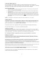 7
7
-
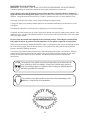 8
8
-
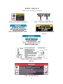 9
9
-
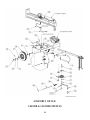 10
10
-
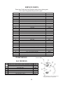 11
11
-
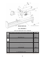 12
12
-
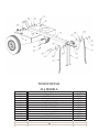 13
13
-
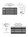 14
14
-
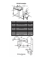 15
15
-
 16
16
-
 17
17
-
 18
18
-
 19
19
-
 20
20
-
 21
21
-
 22
22
-
 23
23
-
 24
24
-
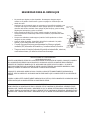 25
25
-
 26
26
-
 27
27
-
 28
28
-
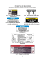 29
29
-
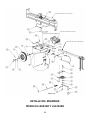 30
30
-
 31
31
-
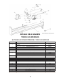 32
32
-
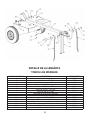 33
33
-
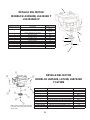 34
34
-
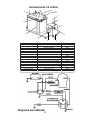 35
35
-
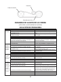 36
36
-
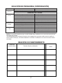 37
37
-
 38
38
-
 39
39
-
 40
40


Swisher LS722B El manual del propietario
- Categoría
- Partidores de troncos
- Tipo
- El manual del propietario
en otros idiomas
- English: Swisher LS722B Owner's manual
Otros documentos
-
Troy-Bilt 24BF572B766 Manual de usuario
-
MTD 510 series El manual del propietario
-
-
Craftsman 247776410 El manual del propietario
-
-
MTD 24AF571C099 El manual del propietario
-
-
-
Cub Cadet 24BG57M1766 Manual de usuario
-
McCulloch Log Splitter FB4052 Manual de usuario