
1
Owner’s Manual
Metered Rack PDUs
Low-Voltage Models: PDUMH15, PDUMH15S, PDUMH20
High-Voltage Models: PDUMH20HV, PDUMH30HV, PDUMH32HV
Español 9 • Français 17 • Русский 25 • Deutsch 33
1111 W. 35th Street, Chicago, IL 60609 USA • www.tripplite.com/support
Copyright © 2019 Tripp Lite. All rights reserved.
PROTECT YOUR INVESTMENT!
Register your product for quicker service
and ultimate peace of mind.
You could also win an
ISOBAR6ULTRA surge protector—
a $100 value!
www.tripplite.com/warranty
21-03-396-933059.indb 121-03-396-933059.indb 1 4/1/2021 11:48:35 AM4/1/2021 11:48:35 AM

2
SAVE THESE INSTRUCTIONS
This manual contains instructions and warnings that should be
followed during the installation, operation and storage of this product.
Failure to heed these instructions may affect your warranty.
CAUTION Only those who are properly trained or qualified to use this device should
do so. Anyone who is not trained or qualified should not use this device unless it is
under the supervision of someone who is properly trained or qualified to do so.
Children must be supervised to ensure that they do not use the device as a toy.
Never use the device if the cord and plug are damaged; if it is not working properly,
or if it has been dropped or damaged, take it to an authorized service center for
inspection and repair.
If the power cord is damaged, it must be replaced by the manufacturer, its authorized
service agent, or by qualified personnel in order to avoid a danger.
Important Warnings
• The PDU provides the convenience of multiple outlets, but DOES NOT provide surge or line
noise protection for connected equipment.
• The PDU is designed for indoor use only, in a controlled environment, away from excess
moisture, temperature extremes, conductive contaminants, dust or direct sunlight.
• Keep indoor ambient temperature between 32°F and 122°F (0°C and 50°C).
• The PDU must be installed by a qualified technician only.
• Do not attempt to mount the PDU to an insecure or unstable surface.
• Install in accordance with National Electrical Code standards. Be sure to use the proper
overcurrent protection for the installation, in accordance with the plug/equipment rating.
• Connect the PDU to an outlet that is in accordance with your local building codes and that is
adequately protected against excess currents, short circuits and earth faults.
• The electrical outlets supplying power to the equipment should be installed near the equipment
and easily accessible.
• Do not connect the PDU to an ungrounded outlet or to extension cords or adapters that
eliminate the connection to ground.
• Be sure to provide a local disconnect device on any models that are permanently installed
without a plug that is easily accessible.
• Never attempt to install electrical equipment during a thunderstorm.
• Individual equipment connected to the PDU should not draw more current than the individual
PDU’s outlet’s rating.
• The total load connected to the PDU must not exceed the maximum load rating for the PDU.
• Do not attempt to modify the PDU, input plugs or power cables.
• Do not drill into or attempt to open any part of the PDU housing. There are no user-serviceable
parts inside.
• Do not attempt to use the PDU if any part of it becomes damaged.
• Use of this equipment in life support applications where failure of this equipment can
reasonably be expected to cause the failure of the life support equipment or to significantly
affect its safety or effectiveness is not recommended.
Important Safety Instructions
21-03-396-933059.indb 221-03-396-933059.indb 2 4/1/2021 11:48:35 AM4/1/2021 11:48:35 AM

3
Installation
A
B
B
C
A
1-1
B
1-2
1-3
Note: The illustrations may differ somewhat from your PDU model.
1
Determine Installation Configuration. The PDUs covered by this owner’s manual support
these installation configurations: 2U, 1U and 0U rackmount; wall-mount and under-counter.
See below for installation configurations pertaining to your specific model. Choose a
configuration and follow the installation instructions in the appropriate section of Step 1
before proceeding to Step 2.
Note: Regardless of installation configuration, the user must determine the fitness of hardware and
procedures before mounting. The PDU and included hardware are designed for common rack and rack
enclosure types and may not be appropriate for all applications. Exact mounting configurations may vary.
1-1
2U Rack Installation. Attach the
included brackets to the side of the
PDU with the included screws
A
. After
installing the brackets, position the
PDU in the rack and install four user-
supplied screws through the unit’s
brackets and into the rack rails
B
.
1-2
1U Rack Installation. Attach the PDU
to the rack by inserting four user-
supplied screws
A
through the PDU
mounting brackets
B
and into the
mounting holes of the rack rail as
shown.
1-3
0U Rack Installation. Part 1: Remove
the screws
C
attaching the mounting
brackets to the PDU, change the
orientation of the brackets as shown
and reattach the brackets. Use only
the screws supplied by the
manufacturer or their exact equivalent
(#6-32, 1/4” flat head). Part 2: Attach
the PDU vertically by inserting two or
more user-supplied screws
A
through
the PDU mounting brackets
B
and
into mounting points in the rack or
rack enclosure.
A
A
B
B
C
21-03-396-933059.indb 321-03-396-933059.indb 3 4/1/2021 11:48:36 AM4/1/2021 11:48:36 AM

4
Installation
1-4
Wall Installation. After repeating Part
1 above, attach the PDU to a stable
mounting surface by inserting two or
more user-supplied screws
A
through
the PDU mounting brackets
B
and
into secure mounting points on the
mounting surface.
1-5
Under-Counter Installation. After
repeating Part 1 above, attach the
PDU to a stable mounting surface by
inserting four user-supplied screws
A
through the PDU mounting brackets
B
and into secure mounting points on
the mounting surface.
A
B
C
B
C
A
C
1-5
1-4
A
A
B
B
C
C
C
2
2
Attach the input plug of the PDU to a grounded
outlet. Insert the plug directly into a grounded
outlet that does not share a circuit with a heavy
electrical load (such as an air conditioner or
refrigerator).
Note: Select models include an input plug adapter that
converts plug types for various applications. See
2-1
for
details.
21-03-396-933059.indb 421-03-396-933059.indb 4 4/1/2021 11:48:36 AM4/1/2021 11:48:36 AM

5
Installation
2-1
88
PDUMH20HV
2-2
2-1C
A
B
C
2-1
NEMA Adapter Connection (Optional -
PDUMH20HV Only): The PDUMH20HV includes a
plug adapter that adds a NEMA L6-20P plug to the
input power cord. Use this adapter only if you will
be connecting the PDUMH20HV to a NEMA L6-20R
outlet. Insert the IEC 60320 C19 connector
A
of
the adapter into the IEC 60320 C20 connector
B
of the input power cord. Secure the connection
with the retention bracket
C
by using the included
bolts to fasten the two halves of the bracket around
the connection as shown.
Caution: To avoid the risk of electric shock,
ensure that the Neutral (L2) conductor has
been identified before connecting the PDU.
2-2
Input Power Cord Connection (PDUMH20HV
Only): Insert the IEC 60320 C19 connector
A
of
the input power cord into the IEC 60320 C20 inlet
B
of the PDU. Connect the other end of the input
power cord
C
to a compatible source of AC power,
such as a UPS system, PDU or utility outlet. The
PDU should be provided with over-current
protection. PDUMH20HV should be provided with a
maximum 20A branch-rated over-current protection
device.
Note: The AC power source should not share a circuit with
a heavy electrical load (such as an air conditioner or
refrigerator).
3
Attach equipment to the PDU. Do not exceed the
load rating of the PDU. The total electrical current
used by the PDU will be displayed on the digital
meter in amperes.
B
A
C
3
21-03-396-933059.indb 521-03-396-933059.indb 5 4/1/2021 11:48:37 AM4/1/2021 11:48:37 AM

6
1
Input Plug (Varies by Model)
2
Outlets (Vary by Model): During normal operation, the
outlets distribute AC power to connected equipment.
3
Circuit Breaker: If the current drawn by the equipment
connected to the PDU exceeds the Maximum Load Rating,
the circuit breaker will trip to prevent possible damage.
When a circuit breaker trips, its plunger will pop up.
Disconnect excess equipment and allow the breaker to cool
at least one minute before depressing the plunger to reset
the breaker.
4
Ammeter: The total electrical current used by the PDU will
be displayed on the digital meter in amperes.
5
Grounding Lug: Use this screw to connect the PDU to
ground.
6
Power Inlet (Select Models): The IEC-320-C20 power
inlet connects to the included power cord or a compatible
user-supplied power cord. The inlet includes a bracket to
secure the cord connection.
7
Input Plug Adapter (Select Models): Converts plug types
for various applications.
NEMA 5-15P
NEMA L5-20P
1
NEMA L6-20P/L6-30P
NEMA 5-15R
NEMA 5-15/20R
IEC-320-C13
IEC-320-C19
5
IEC-320-
C20 INLET
6
NEMA 5-20P
NEMA L5-20R
NEMA L6-20P
IEC-320-C19
2 7
4
3
Thermal 2-Pole Breaker
(PDUMH32HV)
Magnetic, 2-Pole Branch-Rated
Breaker (PDUMH30HV)
Features
21-03-396-933059.indb 621-03-396-933059.indb 6 4/1/2021 11:48:38 AM4/1/2021 11:48:38 AM

7
Features
8 9 10 11 12
8
Longer 1U Mounting Brackets: Use these brackets to mount the 1U PDU horizontally in a
standard rack or rack enclosure. The mounting depth can be adjusted by attaching the
brackets to different positions on the PDU.
9
Shorter 0U Mounting Brackets: Use these brackets to mount the PDU in a 0U rack, wall or
under-counter configuration for 1U PDU models.
10
2U Mounting Brackets: Use these brackets to mount the 2U PDU horizontally in a standard
rack or rack enclosure, or in an under-counter configuration.
11
C14 Plug-Lock Insert Sleeve (Optional): Use the included plastic sleeves to secure C13
power cords to C14 inlets. Fit the sleeve over the end of the cord, making sure the pull-tabs
remain outside the cord and the fit is secure. To unplug equipment properly, grip both the cord
and the insert’s tabs at the same time and pull.
12
C20 Plug-Lock Insert Sleeve (Optional): Use the included plastic sleeves to secure C19
power cords to C20 inlets. Fit the sleeve over the end of the cord, making sure the pull-tabs
remain outside the cord and the fit is secure. To unplug equipment properly, grip both the cord
and the insert’s tabs at the same time and pull.
21-03-396-933059.indb 721-03-396-933059.indb 7 4/1/2021 11:48:38 AM4/1/2021 11:48:38 AM

8
Warranty & Warranty Registration
2-YEAR LIMITED WARRANTY
Seller warrants this product, if used in accordance with all applicable instructions, to be free from original defects
in material and workmanship for a period of 2 years from the date of initial purchase. If the product should
prove defective in material or workmanship within that period, Seller will repair or replace the product, in its sole
discretion. Service under this Warranty can only be obtained by your delivering or shipping the product (with all
shipping or delivery charges prepaid) to: Tripp Lite, 1111 W. 35th Street, Chicago, IL 60609 USA. Seller will pay
return shipping charges. Visit www.tripplite.com/support before sending any equipment back for repair.
THIS WARRANTY DOES NOT APPLY TO NORMAL WEAR OR TO DAMAGE RESULTING FROM ACCIDENT, MISUSE,
ABUSE OR NEGLECT. SELLER MAKES NO EXPRESS WARRANTIES OTHER THAN THE WARRANTY EXPRESSLY
SET FORTH HEREIN. EXCEPT TO THE EXTENT PROHIBITED BY APPLICABLE LAW, ALL IMPLIED WARRANTIES,
INCLUDING ALL WARRANTIES OF MERCHANTABILITY OR FITNESS, ARE LIMITED IN DURATION TO THE WARRANTY
PERIOD SET FORTH ABOVE; AND THIS WARRANTY EXPRESSLY EXCLUDES ALL INCIDENTAL AND CONSEQUENTIAL
DAMAGES. (Some states do not allow limitations on how long an implied warranty lasts, and some states do not
allow the exclusion or limitation of incidental or consequential damages, so the above limitations or exclusions
may not apply to you. This Warranty gives you specific legal rights, and you may have other rights which vary from
jurisdiction to jurisdiction).
WARNING: The individual user should take care to determine prior to use whether this device is suitable, adequate
or safe for the use intended. Since individual applications are subject to great variation, the manufacturer makes
no representation or warranty as to the suitability or fitness of these devices for any specific application.
PRODUCT REGISTRATION
Visit www.tripplite.com/warranty today to register your new Tripp Lite product. You’ll be automatically entered into a
drawing for a chance to win a FREE Tripp Lite product!*
* No purchase necessary. Void where prohibited. Some restrictions apply. See website for details.
FCC Notice, Class A
This device complies with part 15 of the FCC Rules. Operation is subject to the following two conditions: (1) This
device may not cause harmful interference, and (2) this device must accept any interference received, including
interference that may cause undesired operation.
Note: This equipment has been tested and found to comply with the limits for a Class A digital device, pursuant to
part 15 of the FCC Rules. These limits are designed to provide reasonable protection against harmful interference
when the equipment is operated in a commercial environment. This equipment generates, uses, and can radiate
radio frequency energy and, if not installed and used in accordance with the instruction manual, may cause
harmful interference to radio communications. Operation of this equipment in a residential area is likely to cause
harmful interference in which case the user will be required to correct the interference at his own expense.
The user must use shielded cables and connectors with this equipment. Any changes or modifications to this
equipment not expressly approved by Tripp Lite could void the user’s authority to operate this equipment.
Regulatory Compliance Identification Numbers
For the purpose of regulatory compliance certifications and identification, your Tripp Lite product has been
assigned a unique series number. The series number can be found on the product nameplate label, along with
all required approval markings and information. When requesting compliance information for this product, always
refer to the series number. The series number should not be confused with the marking name or model number of
the product.
WEEE Compliance Information for Tripp Lite Customers and Recyclers (European Union)
Under the Waste Electrical and Electronic Equipment (WEEE) Directive and implementing regulations, when
customers buy new electrical and electronic equipment from Tripp Lite they are entitled to:
• Send old equipment for recycling on a one-for-one, like-for-like basis (this varies depending on the country)
• Send the new equipment back for recycling when this ultimately becomes waste
Tripp Lite has a policy of continuous improvement. Specifications are subject to change without notice.
1111 W. 35th Street, Chicago, IL 60609 USA • www.tripplite.com/support
21-03-396 93-3059_revG
21-03-396-933059.indb 821-03-396-933059.indb 8 4/1/2021 11:48:38 AM4/1/2021 11:48:38 AM

9
Manual del propietario
PDU para montaje en rack
(bastidor) con amperímetro
Modelos de Bajo Voltaje: PDUMH15, PDUMH15S, PDUMH20
Modelos de Alta Tensión: PDUMH20HV, PDUMH30HV, PDUMH32HV
English 1 • Français 17 • Русский 25 • Deutsch 33
1111 W. 35th Street, Chicago, IL 60609 USA • www.tripplite.com/support
© 2019 Tripp Lite. Todos los derechos reservados.
21-03-396-933059.indb 921-03-396-933059.indb 9 4/1/2021 11:48:38 AM4/1/2021 11:48:38 AM

10
GUARDE ESTAS INSTRUCCIONES
Este manual contiene instrucciones y advertencias que deben seguirse
durante la instalación, operación y almacenamiento de este producto. La
falta de observar estas advertencias podría afectar su garantía.
PRECAUCION Este aparato no se destina para utilizarse por personas (incluyendo niños),
cuyas capacidades fisicas, sensoriales o mentales sean diferentes o estén reducidas, o
carezcan de experiencia o conocimiento, a menos que dichas personas reciban una supervisión
o capacitación para el funcionamiento del aparato por una persona responsable de su
seguridad.
Los ninos deben de supervisarse para asegurar que no empleen el aparato como juguete.
Nunca utilize el aparato si el cable y la clavija están dañados; si no funciona correctamente o
si se ha caido o dañado, llévelo a un centro de servicio autorizado para que lo examinen y lo
reparen.
Si el cordon de alimentación es dañado, éste debe sustituirse por el fabricante, por su agente
de servicio autorizado o por personal calificado con el fin de evitar un peligro.
Advertencias importantes
• El PDU proporciona la conveniencia de múltiples tomacorrientes, pero NO proporciona
protección contra sobretensión o ruido en la línea para los equipos conectados.
• El PDU está diseñada solo para uso en interiores en un entorno controlado lejos de humedad
excesiva, temperaturas extremas, contaminantes conductivos, polvo o luz del sol directa.
• Mantiene la temperatura ambiente interior entre 32°F y 104°F (0°C y 40°C).
• El PDU debe ser instalado solamente por un técnico calificado.
• No intente instalar el PDU en una superficie inestable o no segura.
• Instale de acuerdo con los reglamentos eléctricos locales. Asegúrese de usar para la instalación
la protección adecuada contra sobrecorriente, de acuerdo con la especificación de la clavija o
del equipo.
• Conecte el PDU a un tomacorriente que esté de acuerdo a los códigos locales de construcción
y que esté correctamente protegido contra corrientes excesivas, cortocircuitos y fallas de
conexión a tierra.
• Los tomacorrientes eléctricos que suministran energía al equipo deben instalarse próximos al
equipo y ser fácilmente accesibles.
• No conecte El PDU a un toma corriente que no esté a tierra o cables de extensión o
adaptadores que eliminen la conexión a tierra.
• Asegúrese de proporcionar un dispositivo local de desconexión, que sea fácilmente accesible,
en cualquier modelo que esté instalado permanentemente sin una clavija.
• Nunca intente instalar equipos eléctricos durante una tormenta eléctrica.
• El equipo individual conectado al PDU no debe consumir más corriente que la de la
especificación de cada tomacorriente individual del PDU.
• La carga total conectada al PDU no debe exceder la capacidad de carga máxima del PDU.
• No intente modificar el PDU, las clavijas de entrada o los cables de alimentación.
• No perfore ni intente abrir ninguna parte del gabinete del PDU. No tiene partes a las que el
usuario pueda dar servicio.
• No intente usar el PDU si se daña cualquier parte.
• No se recomienda el uso de este equipo en aplicaciones de soporte de vida en donde la falla
de este equipo pueda consecuentemente causar la falla del equipo de soporte de vida o afectar
significativamente su seguridad o efectividad.
Instrucciones de seguridad importantes
21-03-396-933059.indb 1021-03-396-933059.indb 10 4/1/2021 11:48:38 AM4/1/2021 11:48:38 AM

11
Instalación
A
B
B
C
A
1-1
B
1-2
1-3
Nota: Las ilustraciones pueden ser un poco diferentes a las de su modelo de PDU.
1
Determine la configuración de la instalación. La PDU soporta cuatro configuraciones
básicas de instalación: Bastidor de 1U, bastidor de 0U, de pared y debajo de mostrador. Elija
una configuración y siga las instrucciones de instalación en la sección apropiada del Paso 1
antes de continuar al Paso 2.
Nota: Independientemente de la configuración, el usuario debe determinar la idoneidad de los materiales
y accesorios así como de los procedimientos antes del montaje. La PDU y el material incluido están
diseñados para racks (bastidores) y cajas de rack (bastidor) comunes, y pueden no ser apropiados para
todas las aplicaciones.
1-1
Montaje en rack 2U: Ajuste los
soportes incluidos en los lados
laterales de la PDU con los tornillos
incluidos
A
. Después de instalar los
soportes, coloque la PDU en el rack e
instale cuatro tornillos suministrados
por el usuario a través de los soportes
de la unidad y dentro de los rieles del
rack
B
.
1-2
Instalación en bastidor de 1U. Fije
la PDU al bastidor insertando cuatro
tornillos suministrados por el usuario
A
a través de los soportes de
montaje
B
de la PDU en los agujeros
de montaje del riel del bastidor como
se muestra.
1-3
Instalación en bastidor de 0U. Parte
1: Retire los tornillos
C
que fijan los
soportes de montaje a la PDU, cambie
la orientación de los soportes como se
muestra y fíjelos nuevamente. Use
solo los tornillos incluidos o sus
equivalentes exactos (#6-32, 1/4” de
cabeza plana). Parte 2: Fije la PDU
verticalmente insertando dos o más
tornillos suministrados por el usuario
A
a través de los soportes de
montaje
B
de la PDU en los puntos
de montaje en el bastidor o la caja del
bastidor.
A
A
B
B
C
21-03-396-933059.indb 1121-03-396-933059.indb 11 4/1/2021 11:48:39 AM4/1/2021 11:48:39 AM

12
Instalación
1-4
Instalación en la pared. Después de
repetir la Parte 1 anterior, fije el PDU
en una superficie estable para su
instalación insertando dos o más
tornillos suministrados por el usuario
A
a través de los soportes de
instalación del PDU
B
en los puntos
seguros para su instalación en la
superficie de instalación.
1-5
Instalación debajo de mostrador.
Después de repetir la Parte 1 anterior,
fije el PDU en una superficie estable
para su instalación insertando quatro
tornillos suministrados por el usuario
A
a través de los soportes de
instalación del PDU
B
en los puntos
seguros para su instalación en la
superficie de instalación.
A
B
C
B
C
A
C
1-5
1-4
A
A
B
B
C
C
C
2
2
Conecte el enchufe de entrada de la PDU a un
contacto conectado a tierra. Inserte el enchufe
directamente en una toma de corriente alterna
conectada a tierra que no comparta el circuito con
alguna carga eléctrica pesada (como un aire
acondicionado o una refrigeradora).
Nota: Modelos selectos incluye un adaptador de clavija
que convierte tipos de enchufes para varias aplicaciones.
Ver
2-1
para detalles.
21-03-396-933059.indb 1221-03-396-933059.indb 12 4/1/2021 11:48:39 AM4/1/2021 11:48:39 AM

13
Instalación
2-1
88
PDUMH20HV
2-2
2-1C
A
B
C
2-1
Adaptador de conexión NEMA (Opcional - para
PDUMH20HV exclusivamente): El PDUMH20HV
incluye un adaptador que incorpora una clavija
NEMA L6-20P al cable de alimentación de entrada.
Utilice este adaptador solamente si va a conectar
el PDUMH20HV a una toma de corriente NEMA L6
20R. Inserte el conector IEC 60320 C19
A
del
adaptador en el conector IEC 60320 C20
B
del
cable de alimentación de entrada. Asegure la
conexión con la abrazadera de retención
C
mediante los tornillos que se incluyen para sujetar
las dos mitades de la abrazadera alrededor de la
conexión, como se muestra.
Precaución: Con el fin de evitar riesgos de
descarga eléctrica, asegúrese de que el cable
de tierra (L2) ha sido identificado antes de
conectar la Unidad de Distribución de Energía
(UDE).
2-2
Conexión de entrada del cable de alimentación
(para PDUMH20HV exclusivamente): Inserte el
conector IEC 60320 C19
A
del cable de entrada
de alimentación en la entrada IEC 60320 C20
B
de la PDU. Conecte el otro extremo del cable de
entrada de alimentación
C
a una fuente
compatible de corriente alterna (CA), como una
fuente de alimentación ininterrumpida UPS y una
PDU, o a un enchufe. La PDU debe contar con
protección contra sobretensiones. El PDUMH20HV
debe contar con un dispositivo de protección de
sobretensiones de 20 A nominales como máximo
por rama.
Nota: La fuente de alimentación de CA no debe compartir
circuito con grandes cargas eléctricas (como la de un
aparato de aire acondicionado o un refrigerador).
3
Conecte equipos a la PDU. Tenga cuidado de no
exceder la capacidad de carga de la PDU. La
corriente eléctrica total usada por la unidad de
distribución de potencia (PDU) será mostrada en el
medidor digital, en amperios.
B
A
C
3
21-03-396-933059.indb 1321-03-396-933059.indb 13 4/1/2021 11:48:40 AM4/1/2021 11:48:40 AM

14
1
Enchufe de entrada (Varía por Modelo)
2
Salidas (Varía por Modelo): Durante la operación normal,
las salidas distribuyen energía CA al equipo conectado.
3
Interruptor automático: Si la corriente consumida por el
equipo conectado al PDU excede la máxima capacidad de
carga, el interruptor automático disparará para evitar
posibles daños. Cuando un interruptor automático dispara,
su émbolo se extiende. Desconecte el equipo en exceso y
permita que el interruptor automático se enfríe un minuto
antes de presionar el émbolo para restablecer el interruptor
automático.
4
Amperímetro: La corriente eléctrica total usada por la
unidad de distribución de potencia (PDU) será mostrada en
el medidor digital, en amperios.
5
Oreja de tierra: Use este tornillo para conectar la PDU
a tierra.
6
Adaptador de Clavija de Entrada (Modelos Selectos):
Convierte la clavija de entrada de media vuelta a una
clavija de entrada de pala recta.
7
Adaptador de Entrada CA (Modelos Selectos):
Convierte los tipos de enchufe para diversas aplicaciones.
NEMA 5-15P
NEMA L5-20P
1
NEMA L6-20P/L6-30P
NEMA 5-15R
NEMA 5-15/20R
IEC-320-C13
IEC-320-C19
5
IEC-320-
C20 INLET
6
NEMA 5-20P
NEMA L5-20R
NEMA L6-20P
IEC-320-C19
2 7
4
3
Interruptor térmico de 2 postes
(PDUMH32HV)
Interruptor magnético de 2
polos, de bifurcación adecuada
(PDUMH30HV)
Características
21-03-396-933059.indb 1421-03-396-933059.indb 14 4/1/2021 11:48:40 AM4/1/2021 11:48:40 AM

15
Características
8 9 10 11 12
8
Soportes de Instalación de 1U más largos: Use estos soportes para instalar la unidad PDU
de 1U horizontalmente en un rack estándar o estante de rack. La profundidad de montaje se
puede ajustar fijando los soportes a diferentes posiciones en la unidad PDU.
9
Soportes de Instalación de 0U cortos: Use estos soportes para instalar el PDU en un rack
de 0U, en configuración de pared o debajo de mostrador para modelos de unidad PDU de 1U.
10
Soportes de Instalación de 2U: Use estos soportes para instalar la unidad PDU de 2U
horizontalmente en un rack estándar o estante de rack, o en una configuración debajo de
mostrador.
11
Manguito de Clavija C14 (Opcional): Use los manguitos plásticos C14 incluidos para
asegurar las clavijas a los tomacorrientes. Acople el manguito a la clavija asegurándose que las
pestañas de tiro permanezcan fuera de la clavija y que la sujeción sea segura. Para
desenchufar correctamente el equipo, use las pestañas de tiro para retirar la clavija y el
manguito del tomacorriente.
12
Manguito de Clavija C20 (Opcional): Use los manguitos plásticos C20 incluidos para
asegurar las clavijas a los tomacorrientes. Acople el manguito a la clavija asegurándose que las
pestañas de tiro permanezcan fuera de la clavija y que la sujeción sea segura. Para
desenchufar correctamente el equipo, use las pestañas de tiro para retirar la clavija y el
manguito del tomacorriente.
21-03-396-933059.indb 1521-03-396-933059.indb 15 4/1/2021 11:48:40 AM4/1/2021 11:48:40 AM

16
Garantía
Garantía limitada por 2 años
TRIPP LITE garantiza por dos (2) años desde la fecha de compra inicial que este producto no tiene defectos
de materiales ni de mano de obra. La obligación TRIPP LITE bajo esta garantía está limitada a la reparación o
reemplazo (A su entera discreción) de cualquier producto defectuoso. Para obtener servicio bajo esta garantía,
debe obtener un número de Autorización de Devolución de Mercancía (RMA) de TRIPP LITE o de un centro de
servicio autorizado de TRIPP LITE. Los productos deben ser regresados a TRIPP LITE o a un centro de servicio
autorizado de TRIPP LITE con los cargos de transporte prepagados y deben acompañarse con una breve
descripción del problema y un comprobante de la fecha y el lugar de compra. Esta garantía no se aplica a equipos
que hayan sido dañados por accidente, negligencia o mal uso, o hayan sido alterados o modificados de alguna
manera.
EXCEPTO COMO SE INDICA EN EL PRESENTE, TRIPP LITE NO HACE GARANTÍAS EXPRESAS O IMPLÍCITAS,
INCLUIDAS GARANTÍAS DE COMERCIABILIDAD Y ADECUACIÓN PARA UN PROPÓSITO PARTICULAR. Algunos
estados no permiten la limitación o exclusión de garantías implícitas; por lo tanto, las limitaciones o exclusiones
antes mencionadas pueden no aplicarse al comprador.
EXCEPTO COMO SE INDICA ANTERIORMENTE, EN NINGÚN CASO TRIPP LITE SERÁ RESPONSABLE POR DAÑOS
DIRECTOS, INDIRECTOS, ESPECIALES, INCIDENTALES O CONSECUENTES QUE SURJAN DEL USO DE ESTE
PRODUCTO, INCLUSO SI SE ADVIERTE SOBRE LA POSIBILIDAD DE TAL DAÑO. Específicamente, TRIPP LITE no
es responsable por ningún costo, como pérdida de utilidades o ingresos, pérdida de equipos, pérdida del uso de
equipos, pérdida de software, pérdida de datos, costos de sustituciones, reclamaciones de terceros o de cualquier
otra forma.
Cumplimiento de las normas de los números de identificación
Para fines de identificación y certificación del cumplimiento de las normas, su producto Tripp Lite tiene asignado
un número de serie único. Puede encontrar el número de serie en la etiqueta de la placa de identificación
del producto, junto con los símbolos de aprobación e información requeridos. Al solicitar información sobre el
cumplimiento de las normas para este producto, siempre mencione el número de serie. El número de serie no
debe ser confundido con el nombre de identificación ni con el número de modelo del producto.
Información de sobre Cumplimiento de la WEEE para Clientes de Tripp Lite y Recicladores
(Unión Europea)
Según la Directiva de Residuos de Aparatos Eléctricos y Electrónicos (Waste Electrical and Electronic
Equipment, WEEE) y sus reglamentos, cuando los clientes compran nuevos equipos eléctricos y electrónicos
a Tripp Lite, tienen derecho a:
• Enviar equipos antiguos para reciclaje según una base de uno por uno, entre productos similares
(esto varía dependiendo del país)
• Enviar el equipo nuevo de vuelta para reciclaje cuando este se convierta finalmente en desecho
Tripp Lite tiene una política de mejora continua. Las especificaciones están sujetas a cambio sin previo aviso.
1111 W. 35th Street, Chicago, IL 60609 USA • www.tripplite.com/support
21-03-396 93-3059_revG
21-03-396-933059.indb 1621-03-396-933059.indb 16 4/1/2021 11:48:41 AM4/1/2021 11:48:41 AM

17
Manual du propriétaire
Unité de distribution
d’alimentation (PDU)
en bâti avec compteur
Modèles Basse Tension: PDUMH15, PDUMH15S, PDUMH20
Modèles Haute Tension: PDUMH20HV, PDUMH30HV, PDUMH32HV
English 1 • Español 9 • Русский 25 • Deutsch 33
1111 W. 35th Street, Chicago, IL 60609 USA • www.tripplite.com/support
Copyright 2019 Tripp Lite. Tous droits réservés.
21-03-396-933059.indb 1721-03-396-933059.indb 17 4/1/2021 11:48:41 AM4/1/2021 11:48:41 AM

18
CONSERVER CES DIRECTIVES
Ce manuel contient des instructions et des mises en garde que vous
devez respecter durant l’installation, l’utilisation et l’entreposage de
ce produit. Ne pas tenir compte de ces mises en garde pourrait
affecter votre garantie.
Importantes mises en garde
• La PDU fournit des prises multiples pratiques, mais elle ne FOURNIT PAS de protection contre
les surtensions ou les bruits de ligne pour l’équipement connecté.
• La PDU est conçue pour être utilisée à l’intérieur uniquement, dans un environnement contrôlé,
à l’écart de l’excès d’humidité, des températures extrêmes, des contaminants conducteurs, de
la poussière et de la lumière directe du soleil.
• Maintenir la température intérieure ambiante entre 0 °C et 50 °C (32 °F et 122 °F).
• La PDU doit être installée par un technicien qualifié seulement.
• Ne pas tenter de monter la PDU sur une surface précaire ou instable.
• Installer conformément aux codes locaux de l’électricité. S’assurer d’utiliser la bonne protection
contre les surintensités pour l’installation, conformément aux valeurs nominales de la fiche et
de l’équipement.
• Branchez la PDU à une prise de courant à une prise de courant qui est conforme aux codes de
bâtiment locaux et qui est dûment protégée contre les courants excessifs, les courts-circuits et
les défauts à la terre.
• Les prises électriques qui alimentent l’équipement doivent être installées à proximité de
l’équipement et être facilement accessibles.
• Ne pas connecter la PDU dans une prise non mise à la masse ou des rallonges électriques ou
des adaptateurs qui éliminent la connexion à la masse.
• S’assurer de fournir un dispositif de déconnexion local pour tous les modèles qui sont installés
en permanence sans fiche facilement accessible.
• Ne jamais essayer d’installer un équipement électrique pendant un orage.
• L’équipement individuel connecté à la PDU ne doit pas excéder la charge nominale des prises
individuelles de la PDU.
• La charge totale connectée à la PDU ne doit pas excéder la charge nominale maximum pour la
PDU.
• Ne pas tenter de modifier la PDU, y compris les fiches d’entrée et les câbles d’alimentation.
• Ne pas percer ou tenter d’ouvrir une quelconque partie du boîtier de la PDU. Il n’existe aucune
pièce réparable par l’utilisateur à l’intérieur.
• Ne pas tenter d’utiliser la PDU si une de ses pièces est endommagée.
• Il n’est pas recommandé d’utiliser cet équipement dans les applications de soutien vital où une
panne de cet équipement serait susceptible de causer une panne de l’équipement de soutien
vital ou d’affecter sérieusement sa sécurité ou son efficacité.
Importantes consignes de sécurité
21-03-396-933059.indb 1821-03-396-933059.indb 18 4/1/2021 11:48:41 AM4/1/2021 11:48:41 AM

19
Installation
A
B
B
C
A
1-1
B
1-2
1-3
Remarque : Les illustrations peuvent être différentes de celles de votre modèle de PDU.
1
Définir la configuration de l’installation. L’unité peut être installé selon quatre
configurations. Baie 1U, Baie 0U, contre un mur ou sous un comptoir. Choisir une
configuration et suivre les consignes d’installation dans la section appropriée de l’étape 1
avant de procéder à l’étape 2.
Remarque : Sans tenir compte de la configuration, l’utilisateur doit déterminer la compatibilité de la
quincaillerie et les procédures avant d’effectuer l’installation. L’unité PDU et la quincaillerie incluse sont
conçues pour des types de bâti et boîtier courants et peuvent ne pas convenir à toutes les applications.
1-1
Montage vertical 2U : Attachez les
supports inclus aux côtés de la PDU à
l’aide des vis fournies
A
. Après avoir
installé les supports, placez la PDU
dans le bâti et installez quatre vis
fournies par l’utilisateur à travers les
supports de l’unité puis dans les rails
du bâti tel qu’illustré
B
.
1-2
Installation en baie 1U. Fixer la PDU
à la baie en insérant quatre vis
A
fournies par l’utilisateur dans les
brides des fixation
B
de l’unité et
dans les trous de fixation de la
glissière de la baie comme indiqué.
1-3
Installation en baie 0U. 1e partie.
Retirer les vis
C
fixant les brides de
fixation à la PDU, changer l’orientation
des brides comme indiqué et les fixer
à nouveau. Utiliser seulement les vis
jointes ou leur équivalent exact (N°
6-32, tête plate 1/4 po [6,4 mm]) 2e
partie : Fixer la PDU verticalement en
insérant deux vis ou plus
A
, fournies
par l’utilisateur dans les brides de
fixation
B
de l’unité et dans les points
de fixation de la baie ou de son boîtier.
A
A
B
B
C
21-03-396-933059.indb 1921-03-396-933059.indb 19 4/1/2021 11:48:41 AM4/1/2021 11:48:41 AM

20
Installation
1-4
Installation murale. Après avoir
effectué la partie 1 ci-dessus, fixer la
PDU sur une surface de fixation stable
en insérant deux vis ou plus
A
fournies par l’utilisateur dans les
supports de montage
B
de la PDU et
dans des points de fixation sûrs de la
surface de montage.
1-5
Installation sous un comptoir. Après
avoir effectué la partie 1 ci-dessus,
fixer la PDU sur une surface de fixation
stable en insérant quatre vis
A
fournies par l’utilisateur dans les
supports de montage
B
) de la PDU et
dans des points de fixation sûrs de la
surface de montage.
A
B
C
B
C
A
C
1-5
1-4
A
A
B
B
C
C
C
2
2
Fixer le fiche d’entrée de l’unité PDU à une
prise mise à la terre. Insérer la fiche directement
dans une prise CA correctement mise à la terre,
qui ne partage pas de circuit supportant une lourde
charge électrique (comme un climatiseur ou un
réfrigérateur).
Remarque: Certains modèles incluent une carte d’entrée
qui convertit les types de prises pour diverses applications.
Voir
2-1
pour plus de détails.
21-03-396-933059.indb 2021-03-396-933059.indb 20 4/1/2021 11:48:42 AM4/1/2021 11:48:42 AM

21
Installation
2-1
88
PDUMH20HV
2-2
2-1C
A
B
C
2-1
Branchement de l’adaptateur NEMA (en option
- PDUMH20HV uniquement) : Le PDUMH20HV
comprend un adaptateur permettant d’ajouter une
fiche NEMA L6-20P au cordon d’alimentation.
N’utilisez cet adaptateur que pour connecter le
PDUMH20HV à une prise NEMA L6-20R. Insérez le
connecteur
A
CEI 60320 C19 de l’adaptateur
dans le connecteur
B
CEI 60320 C20 du cordon
d’alimentation. Sécurisez le branchement avec la
pince de retenue
C
en utilisant les vis fournis pour
fixer les deux moitiés de la pince autour de la
connexion, comme illustré.
Attention : Pour éviter tout risque
d’électrocution, veillez à identifier le
connecteur neutre (L2) avant de connecter la
PDU.
2-2
Branchement du cordon d’alimentation
(PDUMH20HV uniquement) : Insérez le
connecteur
A
CEI 60320 C19 du cordon
d’alimentation dans la prise
B
CEI 60320 C20 de
la PDU. Connectez l’autre extrémité du cordon
C
à
une source de courant c.a. compatible, telle qu’un
système d’alimentation sans interruption (UPS),
une PDU ou une prise électrique. La PDU doit être
munie d’une protection contre les surintensités. Le
PDUMH20HV doit être doté d’un dispositif de
protection contre les surintensités d’une intensité
nominale de 20 A maximum par branche.
Remarque : La source de courant c.a. ne doit pas se
trouver sur le même circuit qu’un appareil à lourde charge
électrique (tel qu’un climatiseur ou un réfrigérateur).
3
Fixer l’équipement à l’unité PDU. Faire attention
de ne pas dépasser la charge nominale de l’unité
PDU. La totalité du courant électrique utilisée par la
PDU sera affichée en ampères au compteur
numérique.
B
A
C
3
21-03-396-933059.indb 2121-03-396-933059.indb 21 4/1/2021 11:48:42 AM4/1/2021 11:48:42 AM

22
1
Fiche d’entrée (Varie selon le modèle)
2
Prises (Varient selon les modèles) : Lors d’un
fonctionnement normal, les prises distribuent du courant
CA à l’équipement connecté.
3
Disjoncteur : Si le courant tiré par l’équipement connecté
à l’unité PDU excède la charge nominale maximale, un
disjoncteur se déclenchera pour empêcher des dommages.
Quand un disjoncteur se déclenche, le poussoir se relève.
Déconnecter l’équipement et laisser le disjoncteur refroidir
une minute avant de rabaisser le poussoir pour réarmer le
disjoncteur.
4
Ampèremètre : La totalité du courant électrique utilisée
par la PDU sera affichée en ampères au compteur
numérique.
5
Cosse de mise à la terre : Utiliser cette vis pour
connecter l’unité PDU à la terre.
6
Adaptateur de fiche d’entrée (certains modèles) :
Convertit la fiche d’entrée à verrouillage rotatif en une fiche
à lames droites.
7
Adaptateur d’entrée de CA (certains modèles) :
Convertit les types de prises pour les différentes
applications.
NEMA 5-15P
NEMA L5-20P
1
NEMA L6-20P/L6-30P
NEMA 5-15R
NEMA 5-15/20R
IEC-320-C13
IEC-320-C19
5
IEC-320-
C20 INLET
6
NEMA 5-20P
NEMA L5-20R
NEMA L6-20P
IEC-320-C19
2 7
4
3
Disjoncteur thermique 2-Pôles
(PDUMH32HV)
Disjoncteur Magnétique,
2-Pôles (PDUMH30HV)
Caractéristiques
21-03-396-933059.indb 2221-03-396-933059.indb 22 4/1/2021 11:48:43 AM4/1/2021 11:48:43 AM

23
Caractéristiques
8 9 10 11 12
8
Supports de montage Longs 1U : Utilisez ces supports pour monter la PDU 1U
horizontalement dans un bâti standard ou une enceinte de support. La profondeur de
l’installation peut être ajustée en attachant les supports à différentes endroits sur la PDU.
9
Supports de montage courts 0U : Utilisez ces supports pour monter la PDU dans un bâti de
support 0U, sur un mur ou pour une configuration sous le comptoir pour les modèles PDU 1U.
10
Supports de montage 2U : Utilisez ces supports pour monter la PDU 2U horizontalement
dans un bâti standard ou une enceinte de support ou pour une configuration sous le comptoir.
11
Manchons de fiche C14 (facultatif) : Utiliser les manchons en plastique C14 inclus pour
retenir les fiches aux prises de courant. Fixer le manchon à la fiche en s’assurant que les
languettes de préhension demeurent à l’extérieur de la fiche et qu’il repose solidement en
place. Pour débrancher correctement l’équipement, utiliser les languettes de préhension pour
retirer la fiche et le manchon de la prise de courant.
12
Manchons de fiche C20 (facultatif) : Utiliser les manchons en plastique C20 inclus pour
retenir les fiches aux prises de courant. Fixer le manchon à la fiche en s’assurant que les
languettes de préhension demeurent à l’extérieur de la fiche et qu’il repose solidement en
place. Pour débrancher correctement l’équipement, utiliser les languettes de préhension pour
retirer la fiche et le manchon de la prise de courant.
21-03-396-933059.indb 2321-03-396-933059.indb 23 4/1/2021 11:48:43 AM4/1/2021 11:48:43 AM

24
Garantie
Garantie limitée de 2 ans
TRIPP LITE garantit que ses produits sont exempts de vices de matériaux et de fabrication pendant une période
de 2 ans à partir de la date d’achat initiale. La responsabilité de TRIPP LITE, en vertu de la présente garantie,
se limite à la réparation ou au remplacement (à sa seule discrétion) de ces produits défectueux. Pour obtenir
réparation sous cette garantie, vous devez obtenir un numéro d’autorisation de retour de matériel (« RMA »)
auprès de TRIPP LITE ou d’un centre de réparation autorisé par TRIPP LITE. Les produits doivent être retournés
à TRIPP LITE ou à un centre de réparation autorisé par TRIPP LITE en port prépayé et être accompagnés d’une
brève description du problème et d’un justificatif de la date et du lieu d’achat. Cette garantie ne s’applique pas au
matériel ayant été endommagé suite à un accident, à une négligence ou à une application abusive, ou ayant été
altéré ou modifié d’une façon quelconque.
SAUF INDICATION CONTRAIRE DANS LES PRÉSENTES, TRIPP LITE N’ÉMET AUCUNE GARANTIE, EXPRESSE OU
TACITE, Y COMPRIS DES GARANTIES DE QUALITÉ COMMERCIALE ET D’ADÉQUATION À UN USAGE PARTICULIER.
Certains États n’autorisant pas la limitation ni l’exclusion de garanties tacites, les limitations ou exclusions
susmentionnées peuvent ne pas s’appliquer à l’acheteur.
À L’EXCEPTION DES DISPOSITIONS CI-DESSUS, TRIPP LITE NE POURRA EN AUCUN CAS ÊTRE TENUE
RESPONSABLE DE DOMMAGES DIRECTS, INDIRECTS, SPÉCIAUX, FORTUITS OU CONSÉCUTIFS RÉSULTANT
DE L’UTILISATION DE CE PRODUIT, MÊME SI AYANT ÉTÉ AVISÉE DE L’ÉVENTUALITÉ DE TELS DOMMAGES. Plus
précisément, TRIPP LITE ne pourra être tenue responsable de coûts, tels que perte de bénéfices ou de recettes,
perte de matériel, impossibilité d’utilisation du matériel, perte de logiciel, perte de données, frais de produits de
remplacement, réclamations d’un tiers ou autres.
Numéros d’identification de conformité aux règlements
À des fins de certification et d’identification de conformité aux règlements, votre produit Tripp Lite a reçu un
numéro de série unique. Ce numéro se retrouve sur la plaque signalétique du produit, avec les inscriptions et
informations d’approbation requises. Lors d’une demande d’information de conformité pour ce produit, utilisez
toujours le numéro de série. Il ne doit pas être confondu avec le nom de la marque ou le numéro de modèle du
produit.
L’information de conformité WEEE pour les clients de Tripp Lite et recycleurs (Union européenne)
Sous les directives et règlements de déchet d’équipements électrique et électronique (Waste Electrical and
Electronic Equipment, WEEE), lorsque les clients achètent le matériel électrique et électronique neuf de
Tripp Lite ils sont autorisés à :
• Envoyer le vieux matériel pour le recyclage sur une base de un-contre-un et en nature (ceci varie selon le
pays)
• Renvoyer le matériel neuf pour recyclage quand ceci devient éventuellement un rebut
La politique de Tripp Lite en est une d’amélioration continue. Les spécifications sont sujettes à changement sans
préavis.
1111 W. 35th Street, Chicago, IL 60609 USA • www.tripplite.com/support
21-03-396 93-3059_revG
21-03-396-933059.indb 2421-03-396-933059.indb 24 4/1/2021 11:48:43 AM4/1/2021 11:48:43 AM

25
Руководство
пользователя
Стоечные PDU с
измерителем
Низковольтные модели: PDUMH15, PDUMH15S, PDUMH20
Высоковольтные модели: PDUMH20HV, PDUMH30HV, PDUMH32HV
English 1 • Español 9 • Français 17 • Deutsch 33
1111 W. 35th Street, Chicago, IL 60609 USA • www.tripplite.com/support
Copyright © 2019 Tripp Lite. Перепечатка запрещается.
21-03-396-933059.indb 2521-03-396-933059.indb 25 4/1/2021 11:48:43 AM4/1/2021 11:48:43 AM

26
СОХРАНИТЕ НАСТОЯЩИЕ УКАЗАНИЯ В
настоящем руководстве содержатся указания и предупреждения,
которые необходимо соблюдать в процессе установки, эксплуатации и
хранения данного изделия. Игнорирование этих указаний и
предупреждений может привести к потере гарантии на изделие.
Важные предупреждения
• Блок распределения питания (PDU) удобно оснащен несколькими розетками, но НЕ
обеспечивает защиту подключенного оборудования от выбросов напряжения и шумов в линии.
• Блок распределения питания (PDU) предназначен только для использования в закрытых
помещениях с регулируемым микроклиматом вдали от источников повышенной влажности,
экстремальных температур, электропроводных загрязнителей, пыли и прямого солнечного света.
• Поддерживайте температуру воздуха внутри помещения в диапазоне от 0°C до 50°C.
• Установка блока распределения питания (PDU) должна производиться только
квалифицированным техническим специалистом.
• Не устанавливайте блок распределения питания (PDU) на незакрепленной или неустойчивой
поверхности.
• Установку следует производить в соответствии с местными электротехническими нормами и
правилами. Обязательно используйте подходящие для устанавливаемой системы устройства
защиты от перегрузок по току в соответствии с номиналами, указанными на разъемах/
оборудовании.
• Подключите блок распределения питания (PDU) к розетке, соответствующей принятым в вашей
стране строительным нормам и надлежащим образом защищенной от избыточных токов,
коротких замыканий и замыканий на землю.
• Электрические розетки, через которые осуществляется электропитание оборудования, должны
быть установлены в легкодоступном месте вблизи него.
• Не подключайте блок распределения питания (PDU) к незаземленной розетке, а также к
удлинителям или переходникам, не имеющим заземления.
• Обязательно снабжайте любые модели, подключаемые неразъемным способом, легкодоступным
локальным устройством защитного отключения.
• Ни в коем случае не производите монтаж электрооборудования во время грозы.
• Ток, потребляемый отдельными элементами оборудования, подключаемыми к блоку
распределения питания (PDU), не должен превышать номинал соответствующих розеток блока
распределения питания (PDU).
• Суммарная нагрузка, создаваемая потребителями, подключенными к блоку распределения
питания (PDU), не должна превышать его максимально допустимую нагрузку.
• Не вносите изменений в конструкцию блока распределения питания (PDU), входных разъемов
или кабелей питания.
• Не высверливайте отверстий в корпусе блока распределения питания (PDU) и не пытайтесь
вскрыть какую-либо его часть. Внутри него нет деталей, обслуживаемых пользователем.
• Не используйте блока распределения питания (PDU) в случае повреждения любой из его частей.
• Не рекомендуется использование данного оборудования в системах жизнеобеспечения, где его
выход из строя предположительно может привести к перебоям в работе оборудования
жизнеобеспечения или в значительной мере снизить его безопасность или эффективность.
Важные указания по технике безопасности
21-03-396-933059.indb 2621-03-396-933059.indb 26 4/1/2021 11:48:43 AM4/1/2021 11:48:43 AM

27
Установка
A
B
B
C
A
1-1
B
1-2
1-3
Примечание. Устройство, изображенное на иллюстрациях, может несколько отличаться от вашей модели PDU.
1
Определение установочной конфигурации. Блоки распределения питания (PDU),
описываемые в настоящем руководстве, могут использоваться в следующих установочных
конфигурациях: монтаж в стойку (2U, 1U и 0U), настенный монтаж и монтаж под прилавком.
Установочные конфигурации, относящиеся к вашей конкретной модели, представлены ниже.
Выберите один из типов конфигурации и следуйте указаниям по установке в соответствующем
разделе шага 1, после чего переходите к шагу 2.
Примечание. Независимо от конфигурации установки пользователь должен установить пригодность
оснастки и предполагаемых процедур до начала монтажа. Блок распределения питания (PDU) и входящая в
его комплект оснастка предназначены для обычных типов шкафов и могут не подходить для всех целей
применения. Установочные конфигурации могут различаться в деталях.
1-1
Установка в шкаф высотой 2U.
Прикрепите поставляемые в комплекте
кронштейны к боковой панели PDU при
помощи винтов
A
из комплекта.
После установки кронштейнов
разместите PDU в шкафу и
зафиксируйте его путем ввертывания
четырех не входящих в комплект
поставки крепежных винтов через
кронштейны в направляющие шкафа
B
.
1-2
Установка в шкаф высотой 1U.
Закрепите PDU в шкафу путем
ввертывания четырех винтов
A
(не
входящих в комплект поставки) через
монтажные кронштейны PDU
B
в
монтажные отверстия направляющей
шкафа, как показано на рисунке.
1-3
Вертикальная установка в шкаф
(0U). Часть 1: Выверните винты
C
,
обеспечивающие крепление
монтажных кронштейнов к PDU,
измените положение кронштейнов, как
показано на рисунке, и прикрепите
кронштейны на прежнее место.
Используйте только винты,
поставляемые производителем, или их
полный аналог (#6-32, 1/4” с потайной
головкой). Часть 2: Прикрепите PDU
вертикально путем ввертывания двух
или более винтов
A
(не входящих в
комплект поставки) через монтажные
кронштейны PDU
B
в монтажные
отверстия стойки или шкафа.
A
A
B
B
C
21-03-396-933059.indb 2721-03-396-933059.indb 27 4/1/2021 11:48:44 AM4/1/2021 11:48:44 AM

28
Установка
1-4
Настенный монтаж. После повторения
действий, описанных выше в Части 1,
прикрепите PDU к устойчивой
монтажной поверхности путем
ввертывания двух или более винтов
A
(не входящих в комплект поставки)
через монтажные кронштейны PDU
B
в монтажные отверстия на монтажной
поверхности.
1-5
Монтаж под прилавком. После
повторения действий, описанных выше
в Части 1, прикрепите PDU к
устойчивой монтажной поверхности
путем ввертывания четырех винтов
A
(не входящих в комплект поставки)
через монтажные кронштейны PDU
B
в монтажные отверстия на монтажной
поверхности.
A
B
C
B
C
A
C
1-5
1-4
A
A
B
B
C
C
C
2
2
Включите штепсельный разъем входного
кабеля PDU в заземленную розетку
электрической сети. Разъем следует включать
непосредственно в заземленную розетку, не
находящуюся в общем контуре с большой
электрической нагрузкой (такой как кондиционер
или холодильник).
Примечание. Некоторые модели комплектуются
переходной вилкой, преобразующей входной разъем
данного типа в разъемы других типов. Подробнее см
.
2-1
.
21-03-396-933059.indb 2821-03-396-933059.indb 28 4/1/2021 11:48:44 AM4/1/2021 11:48:44 AM

29
Установка
2-1
88
PDUMH20HV
2-2
2-1C
A
B
C
2-1
Подключение переходника NEMA
(необязательно; только для мод. PDUMH20HV):
модель PDUMH20HV оснащается штепсель-
переходником, который обеспечивает шнур питания
дополнительным разъемом типа NEMA L6-20P. Этот
переходник следует использовать только при
подключении устройства модели PDUMH20HV к
розетке типа NEMA L6-20R. Вставьте разъем IEC
60320 C19
A
переходника в разъем IEC 60320 C20
B
входного шнура питания. Зафиксируйте
соединение при помощи зажимов для фиксации
кабеля
C
с использованием входящих в комплект
болтов, скрепляющих две части зажима вокруг
разъема, как показано на рисунке.
Внимание! Во избежание опасности поражения
электрическим током необходимо распознать
нейтральный провод (L2) перед подключением
PDU.
2-2
Подключение входного шнура питания (только
для мод. PDUMH20HV): вставьте разъем IEC 60320
C19
A
входного шнура питания во входной разъем
типа IEC 60320 C20
B
блока распределения
питания (PDU). Подключите другой конец входного
шнура питания
C
к совместимому источнику
питания переменного тока (например, ИБП, PDU
или розетке электрической сети). PDU должен быть
оснащен защитой от перегрузок по току. Устройство
PDUMH20HV должно оснащаться устройством
защиты от перегрузок по току номиналом не более
20A.
Примечание. Источник питания переменного тока не
должен находиться в общем контуре с большой
электрической нагрузкой (такой как кондиционер или
холодильник).
3
Подключите оборудование к PDU. Не
превышайте номинальную нагрузку PDU.
Суммарный электрический ток, потребляемый PDU,
высвечивается на индикаторе цифрового
измерителя в амперах.
B
A
C
3
21-03-396-933059.indb 2921-03-396-933059.indb 29 4/1/2021 11:48:44 AM4/1/2021 11:48:44 AM

30
1
Входной разъем (в зависимости от модели)
2
Розетки (в зависимости от модели): в штатном режиме
работы розетки распределяют мощность переменного тока
между подключенными к ним элементами оборудования.
3
Автоматический выключатель: если ток, потребляемый
оборудованием, подключенным к PDU, превышает его
максимально допустимую нагрузку, то происходит срабатывание
автоматического выключателя во избежание возможного выхода
оборудования из строя. При срабатывании автоматического
выключателя его кнопка выскакивает вверх. Перед сбросом
автоматического выключателя нажатием кнопки следует
отсоединить оборудование, создающее избыточную нагрузку, и
дать выключателю возможность охладиться в течение одной
минуты.
4
Амперметр: суммарный электрический ток, потребляемый PDU,
высвечивается на индикаторе цифрового измерителя в амперах.
5
Клемма заземления: заземлите PDU с помощью этого винта.
NEMA 5-15P
NEMA L5-20P
1
NEMA L6-20P/L6-30P
NEMA 5-15R
NEMA 5-15/20R
IEC-320-C13
IEC-320-C19
5
IEC-320-
C20 INLET
6
NEMA 5-20P
NEMA L5-20R
NEMA L6-20P
IEC-320-C19
2 7
4
3
Disjoncteur thermique 2-Pôles
(PDUMH32HV)
Disjoncteur Magnétique,
2-Pôles (PDUMH30HV)
Характеристики продукта
6
Входной разъем питания (для отдельных моделей): входной разъем питания IEC-320-C20
подключается к поставляемому в комплекте шнуру питания или к приобретаемому отдельно
шнуру питания, совместимому с ним. Для фиксации подсоединенного шнура питания входной
разъем оснащен специальным кронштейном.
7
Переходник входного разъема (для отдельных моделей): преобразует входной разъем
данного типа в разъемы других типов.
21-03-396-933059.indb 3021-03-396-933059.indb 30 4/1/2021 11:48:45 AM4/1/2021 11:48:45 AM

31
Характеристики продукта
8 9 10 11 12
8
Удлиненные монтажные кронштейны размером 1U: используйте эти кронштейны для
горизонтального монтажа PDU размером 1U в стандартную стойку или шкаф. Монтажная
глубина может регулироваться путем крепления кронштейнов к другим точкам PDU.
9
Укороченные монтажные кронштейны для вертикального монтажа: используйте эти
кронштейны для вертикального монтажа PDU в стойку (0U), а также на стену или под прилавок
(для моделей PDU высотой 1U).
10
Монтажные кронштейны размером 2U: используйте эти кронштейны для горизонтального
монтажа PDU размером 2U в стандартную стойку или шкаф либо для монтажа под прилавком.
11
Муфта разъема С14 (опция): зафиксируйте разъемы в розетках при помощи входящих в
комплект пластмассовых муфт под разъемы C14. Прикрепите муфту к разъему, убедившись в
том, что ее язычки остаются за пределами разъема и плотно прилегают к нему. Для
правильного отсоединения оборудования следует вынимать разъем с муфтой из розетки,
держась за язычки.
12
Муфта разъема С20 (опция): зафиксируйте разъемы в розетках при помощи входящих в
комплект пластмассовых муфт под разъемы C20. Прикрепите муфту к разъему, убедившись в
том, что ее язычки остаются за пределами разъема и плотно прилегают к нему. Для
правильного отсоединения оборудования следует вынимать разъем с муфтой из розетки,
держась за язычки.
21-03-396-933059.indb 3121-03-396-933059.indb 31 4/1/2021 11:48:45 AM4/1/2021 11:48:45 AM

32
Гарантийные обязательства
Ограниченная гарантия 2 год
TRIPP LITE гарантирует отсутствие дефектов материалов и изготовления в течение одного 2 год с момента
первоначальной покупки. Обязательства компании TRIPP LITE по настоящей гарантии ограничиваются ремонтом
или заменой (по ее единоличному усмотрению) любых таких дефектных изделий. Для получения услуг по данной
гарантии необходимо получить номер Returned Material Authorization (RMA - разрешение на возврат материалов)
от компании TRIPP LITE или ее авторизованного сервисного центра. Изделия должны быть возвращены в
компанию TRIPP LITE или авторизованный сервисный центр TRIPP LITE с предоплатой транспортных расходов
и сопровождаться кратким описанием возникшей проблемы и документом, подтверждающим дату и место его
приобретения. Действие настоящей гарантии не распространяется на оборудование, поврежденное в результате
аварии, небрежного обращения или неправильного использования, а также видоизмененное каким бы то ни было
образом.
ЗА ИСКЛЮЧЕНИЕМ ПРЕДУСМОТРЕННЫХ ЗДЕСЬ СЛУЧАЕВ КОМПАНИЯ TRIPP LITE НЕ ПРЕДОСТАВЛЯЕТ
КАКИХ-ЛИБО ЯВНЫХ ИЛИ ПОДРАЗУМЕВАЕМЫХ ГАРАНТИЙ, ВКЛЮЧАЯ ГАРАНТИИ КОММЕРЧЕСКОЙ
ПРИГОДНОСТИ И ПРИГОДНОСТИ ДЛЯ КАКОЙ-ЛИБО КОНКРЕТНОЙ ЦЕЛИ. В некоторых штатах/государствах
ограничение или исключение подразумеваемых гарантий не допускается; следовательно, вышеуказанное(-ые)
ограничение(-я) или исключение(-я) могут не распространяться на покупателя.
ЗА ИСКЛЮЧЕНИЕМ ПРЕДУСМОТРЕННЫХ ВЫШЕ СЛУЧАЕВ КОМПАНИЯ TRIPP LITE НИ ПРИ КАКИХ
ОБСТОЯТЕЛЬСТВАХ НЕ НЕСЕТ ОТВЕТСТВЕННОСТИ ЗА ПРЯМЫЕ, КОСВЕННЫЕ, СЛУЧАЙНЫЕ ИЛИ
ПОБОЧНЫЕ УБЫТКИ ЛИБО УБЫТКИ, ОПРЕДЕЛЯЕМЫЕ ОСОБЫМИ ОБСТОЯТЕЛЬСТВАМИ, ВОЗНИКАЮЩИЕ
В СВЯЗИ С ИСПОЛЬЗОВАНИЕМ ДАННОГО ИЗДЕЛИЯ, ДАЖЕ В СЛУЧАЕ ЕЕ ИНФОРМИРОВАНИЯ О
ВОЗМОЖНОСТИ НАСТУПЛЕНИЯ ТАКИХ УБЫТКОВ. В частности, компания TRIPP LITE не несет ответственности
за какие-либо издержки, такие как упущенные прибыли или доходы, потеря оборудования, потеря возможности
использования оборудования, потеря программн.
Идентификационные номера, свидетельствующие о соответствии нормативным требованиям
С целью идентификации, а также сертификации соответствия нормативным требованиям, приобретенному Вами
изделию компании Tripp Lite присвоен уникальный серийный номер. Серийный номер, вместе со всей необходимой
информацией и маркировками об одобрении, указан на ярлыке изготовителя, прикрепленном к изделию. При
запросе информации о соответствии нормативным требованиям всегда сообщайте серийный номер изделия. Не
следует путать серийный номер с маркой или номером модели изделия.
Информация для клиентов компании Tripp Lite о соблюдении требований директивы ЕС об отходах
электрического и электронного оборудования (WEEE)
Согласно директиве ЕС об отходах электрического и электронного оборудования (WEEE) и применимым
нормам в случаях, когда покупатели приобретают новое электрическое и электронное оборудование
компании Tripp Lite, они имеют право на следующее:
• Отправку старого оборудования, которое является эквивалентным по количеству и идентичным
полученному новому оборудованию, на утилизацию (это условие может отличаться в зависимости от
страны)
• Отправку нового оборудования обратно на утилизацию, когда оно в конечном итоге становится
изношенным
Компания Tripp Lite постоянно совершенствует свою продукцию. В связи с этим возможно изменение технических
характеристик без предварительного уведомления.
1111 W. 35th Street, Chicago, IL 60609 USA • www.tripplite.com/support
21-03-396 93-3059_revG
21-03-396-933059.indb 3221-03-396-933059.indb 32 4/1/2021 11:48:46 AM4/1/2021 11:48:46 AM

33
Benutzerhandbuch
PDU mit passendem Rahmen
Niederspannungsmodelle: PDUMH15, PDUMH15S, PDUMH20
Hochspannungsmodelle: PDUMH20HV, PDUMH30HV, PDUMH32HV
English 1 • Español 9 • Français 17 • Русский 25
1111 W. 35th Street, Chicago, IL 60609 USA • www.tripplite.com/support
Copyright © 2019 Tripp Lite. Alle Rechte vorbehalten.
21-03-396-933059.indb 3321-03-396-933059.indb 33 4/1/2021 11:48:46 AM4/1/2021 11:48:46 AM

34
BITTE BEWAHREN SIE DIESE ANLEITUNG AUF
Die vorliegende Betriebsanleitung enthält Anweisungen und
Warnhinweise, die bei Installation, Betrieb und Lagerung des hierin
beschriebenen Produkts befolgt werden sollten. Die Nichtbeachtung
dieser Anweisungen kann Ihre Garantie beeinträchtigen.
Wichtige Sicherheitswarnungen
• Die PDU bietet den Komfort mehrerer Ausgänge, bietet jedoch KEINEN Schutz vor
Überspannung oder Leitungsgeräuschen für angeschlossene Geräte.
• Die PDU wurde für den Betrieb in Innenräumen konzipiert. Sie darf nur in einer kontrollierten
Umgebung verwendet werden und muss vor übermäßiger Feuchtigkeit, extremen Temperaturen,
leitfähigen Schmutzstoffen, Staub sowie direkter Sonneneinstrahlung geschützt werden.
• Halten Sie die Innentemperatur zwischen 0 °C und 50 °C.
• Die PDU darf nur von einem qualifizierten Techniker installiert werden.
• Versuchen Sie nicht, die PDU auf einer unsicheren oder instabilen Oberfläche zu montieren.
• Installieren Sie die PDU gemäß den nationalen Elektrorichtlinien. Vergewissern Sie sich, dass
Sie für die Installation einen geeigneten Überstromschutz gemäß der Stecker-/Geräteleistung
verwenden.
• Schließen Sie die PDU an eine Steckdose an, die den örtlichen Bauvorschriften entspricht und
ausreichend gegen Überstrom, Kurzschluss und Erdschluss geschützt ist.
• Die Netzsteckdosen, die das Gerät mit Energie versorgen, sollten in der Nähe des Geräts
installiert werden und einfach zugänglich sein.
• Schließen Sie die PDU nicht an eine ungeerdete Steckdose oder an Verlängerungskabel oder
Adapter an, durch die der Masseanschluss unterbrochen wird.
• Stellen Sie ein lokales Trenngerät für alle Modelle bereit, die dauerhaft ohne leicht zugänglichen
Stecker installiert sind.
• Versuchen Sie niemals, elektrische Geräte während eines Gewitters anzuschließen.
• Einzelgeräte, die an die PDU angeschlossen sind, sollten nicht mehr Strom ziehen als den
Nennwert der jeweiligen PDU-Steckdose.
• Die an die PDU angeschlossene Gesamtlast darf die maximale Strombelastbarkeit der PDU nicht
überschreiten.
• Versuchen Sie nicht, die PDU, die Eingangsstecker oder die Stromkabel auszuwechseln.
• Bohren Sie nicht in das Gehäuse der PDU und versuchen Sie auch nicht, es zu öffnen. Die PDU
enthält keine Teile, die vom Benutzer gewartet werden können.
• Versuchen Sie nicht, die PDU zu verwenden, wenn ein Teil davon beschädigt ist.
• Die Verwendung dieses Geräts für Lebenserhaltungssysteme, in denen der Ausfall des Geräts
den Ausfall des Lebenserhaltungssystems verursachen oder dessen Sicherheit beziehungsweise
Wirksamkeit bedeutend beeinträchtigen kann, wird nicht empfohlen.
Wichtige Sicherheitshinweise
21-03-396-933059.indb 3421-03-396-933059.indb 34 4/1/2021 11:48:46 AM4/1/2021 11:48:46 AM

35
Installation
A
B
B
C
A
1-1
B
1-2
1-3
Hinweis: Die Abbildungen können sich leicht von Ihrem PDU-Modell unterscheiden.
1
Installationskonfiguration festlegen. Die in diesem Benutzerhandbuch abgedeckten PDUs
beinhalten diese Installationskonfigurationen: 2-HE-, 1-HE- und 0-HE-Rack-Installation;
Wandinstallation und Unterbauinstallation. Nachstehend sehen Sie die
Installationskonfigurationen für Ihr spezifisches Modell. Entscheiden Sie sich für eine
Konfiguration und befolgen Sie die Installationsanweisungen im entsprechenden Abschnitt von
Schritt 1, bevor Sie mit Schritt 2 fortfahren.
Hinweis: Unabhängig von der Installationskonfiguration muss der Benutzer vor der Installation sicherstellen,
dass das verwendete Material und die Verfahren dafür geeignet sind. Die PDU und das beiliegende Material
wurden für den Einsatz in Kombination mit üblichen Rack-Arten und -Gehäusen konzipiert und eignen sich
möglicherweise nicht für alle Anwendungsbereiche. Die genauen Installationskonfigurationen können
variieren.
1-1
2-HE-Rack-Installation. Befestigen
Sie die mitgelieferten Halterungen mit
den mitgelieferten Schrauben seitlich
an der PDU
A
. Positionieren Sie die
PDU nach dem Installieren der
Halterungen im Rack und installieren
Sie die vier vom Benutzer
bereitgestellten Schrauben in den
Halterungen der Einheit und in den
Rackschienen
B
.
1-2
1-HE-Rack-Installation. Befestigen
Sie die PDU am Rack, indem Sie vier
der mitgelieferten Schrauben
A
in die
PDU-Montagehalterungen
B
und in
die Befestigungslöcher der
Rackschiene drehen (siehe Schaubild).
1-3
0-HE-Rack-Installation. Teil 1:
Entfernen Sie die Schrauben
C
, mit
denen die Montagehalterungen an der
PDU befestigt sind, ändern Sie die
Ausrichtung der Halterungen wie
abgebildet und bringen Sie die
Halterungen wieder an. Verwenden Sie
ausschließlich die vom Hersteller
mitgelieferten Schrauben oder deren
exakte Entsprechung (US-Standard
Flachkopfschraube, 6-32 x 1/4"). Teil
2: Befestigen Sie die PDU vertikal,
indem Sie zwei oder mehr der
mitgelieferten Schrauben
A
in die
PDU-Montagehalterungen
B
drehen
und an den Befestigungspunkten im
Rack oder im Rackgehäuse befestigen.
A
A
B
B
C
21-03-396-933059.indb 3521-03-396-933059.indb 35 4/1/2021 11:48:46 AM4/1/2021 11:48:46 AM

36
Installation
1-4
Wandmontage. Nachdem Sie Teil 1
oben wiederholt haben, befestigen Sie
die PDU an einer stabilen
Montagefläche, indem Sie zwei oder
mehr mitgelieferte Schrauben
A
durch die PDU-Montagehalterungen
B
führen und in den sicheren
Befestigungspunkten auf der
Montagefläche festdrehen.
1-5
Untertischinstallation. Nachdem Sie
Teil 1 oben wiederholt haben,
befestigen Sie die PDU an einer
stabilen Montagefläche, indem Sie vier
oder mehr mitgelieferte Schrauben
A
durch die PDU-Montagehalterungen
B
führen und in den sicheren
Befestigungspunkten auf der
Montagefläche festdrehen.
A
B
C
B
C
A
C
1-5
1-4
A
A
B
B
C
C
C
2
2
Stecken Sie den Eingangsstecker der PDU in
eine geerdete Steckdose. Stecken Sie den
Stecker direkt in eine geerdete Steckdose, die nicht
an einem Stromkreis mit einer hohen elektrischen
Ladung, wie z. B. bei Klimaanlagen oder
Kühlschränken, angeschlossen ist.
Hinweis: Einige Modelle verfügen über einen Adapter für
den Eingangsstecker, der die Stecker für unterschiedliche
Anwendungen anpasst. Weitere Informationen finden Sie
auf
2-1
.
21-03-396-933059.indb 3621-03-396-933059.indb 36 4/1/2021 11:48:46 AM4/1/2021 11:48:46 AM

37
Installation
2-1
88
PDUMH20HV
2-2
2-1C
A
B
C
2-1
NEMA-Adapterverbindung (optional ‒ nur
PDUMH20HV): Das Modell PDUMH20HV verfügt
über einen Steckeradapter, der das Stromkabel mit
einem NEMA L6-20P-Stecker ausstattet.
Verwenden Sie diesen Adapter nur, wenn Sie das
Modell PDUMH20HV an einen NEMA L6-20R-
Ausgang anschließen. Stecken Sie die IEC 60320
C19-Verbindung
A
des Adapters in die IEC 60320
C20-Verbindung
B
des Stromkabels. Sichern Sie
die Verbindung mit der Kabelhaltehalterung
C
,
indem Sie die beiden mitgelieferten Schrauben
dazu verwenden, die beiden Hälften der Halterung
wie im Schaubild um die Verbindung zu befestigen.
Achtung: Um die Gefahr eines Stromschlags zu
verhindern, stellen Sie sicher, dass der
Nullleiter (L2) vor dem Anschließen der PDU
identifiziert wurde.
2-2
Anschließen des Stromkabels (nur
PDUMH20HV): Stecken Sie die IEC 60320 C19-
Verbindung
A
des Stromkabels in den IEC 60320
C20-Eingang
B
der PDU. Schließen Sie das
andere Ende des Netzkabels
C
an eine kompatible
Wechselstromquelle an, z. B. an ein USV-System,
eine PDU oder eine Steckdose. Die PDU sollte mit
einem Überspannungsschutz ausgestattet werden.
Das Modell PDUMH20HV sollte mit einem
Überspannungsschutz mit einer
Abzweigschutzeinrichtung mit maximal 20 A
ausgestattet werden.
Hinweis: Die Wechselstromquelle sollte nicht an einem
Stromkreis mit einer hohen elektrischen Ladung wie z. B.
bei Klimaanlagen oder Kühlschränken angeschlossen sein.
3
Schließen Sie das Gerät an die PDU an. Achten
Sie darauf, dass die zulässige Strombelastbarkeit
der PDU nicht überschritten wird. Der von der PDU
verbrauchte elektrische Gesamtstrom wird in
Ampere auf dem Digitalzähler angezeigt.
B
A
C
3
21-03-396-933059.indb 3721-03-396-933059.indb 37 4/1/2021 11:48:47 AM4/1/2021 11:48:47 AM

38
1
Eingangsstecker (variiert je nach Modell)
2
Steckdosen (je nach Modell unterschiedlich): Während des
normalen Betriebs verteilen die Steckdosen den Wechselstrom
auf die angeschlossenen Geräte.
3
Leistungsschalter: Wenn der von dem an die PDU
angeschlossenen Gerät gezogene Strom die maximale
Belastbarkeit überschreitet, schaltet der Leistungsschalter ab,
um mögliche Schäden zu vermeiden. Wenn ein Leistungsschalter
ausgelöst wird, zeigt der Kolben nach oben. Trennen Sie
überzählige Geräte und lassen Sie den Trennschalter mindestens
eine Minute lang abkühlen. Drücken Sie anschließend den
Kolben nach unten, um den Trennschalter zurückzusetzen.
4
Amperemeter: Der von der PDU verbrauchte elektrische
Gesamtstrom wird in Ampere auf dem Digitalzähler angezeigt.
5
Erdungsklemme: Nutzen Sie diese Schraube, um die PDU mit
der Erdung zu verbinden.
6
Stromeingang (einige Modelle): Der IEC-320-C20-
Stromeingang wird an das mitgelieferte Stromkabel oder ein
kompatibles vom Benutzer bereitgestelltes Stromkabel
angeschlossen. Der Eingang verfügt über eine Halterung, um die
Kabelverbindung zu sichern.
7
Adapter Eingangsstecker (einige Modelle): Passt die
Steckertypen für unterschiedliche Anwendungen an.
NEMA 5-15P
NEMA L5-20P
1
NEMA L6-20P/L6-30P
NEMA 5-15R
NEMA 5-15/20R
IEC-320-C13
IEC-320-C19
5
IEC-320-
C20-EINGANG
6
NEMA 5-20P
NEMA L5-20R
NEMA L6-20P
IEC-320-C19
2 7
4
3
Thermischer 2-poliger
Unterbrecher (PDUMH32HV)
Magnetischer 2-poliger
Abzweigunterbrecher
(PDUMH30HV)
Ausstattung
21-03-396-933059.indb 3821-03-396-933059.indb 38 4/1/2021 11:48:48 AM4/1/2021 11:48:48 AM

39
Ausstattung
8 9 10 11 12
8
Längere 1-HE-Installationshalterungen: Nutzen Sie diese Halterungen, um die 1-HE-PDU
horizontal an einem Standardrack oder einem Rackgehäuse zu installieren. Die Installationstiefe
kann angepasst werden, indem die Halterungen in unterschiedlichen Positionen an der PDU
installiert werden.
9
Kürzere 0-HE-Installationshalterungen: Nutzen Sie diese Halterungen, um die PDU an
einem 0-HE-Rack, an einer Wand oder mit der Unterbaukonfiguration zu montieren, für
1-HE-PDU-Modelle.
10
2-HE-Installationshalterungen: Nutzen Sie diese Halterungen, um die 2-HE-PDU horizontal
an einem Standardrack oder einem Rackgehäuse oder in der Unterbaukonfiguration zu
installieren.
11
C14-Steckersperren-Einsatzhülse (optional): Verwenden Sie die mitgelieferten
Kunststoffhülsen, um C13-Stromkabel an C14-Eingängen zu sichern. Legen Sie die Hülse über
das Ende des Stromkabels und achten Sie darauf, dass die Zuglaschen außerhalb des Kabels
bleiben, damit die Passung sicher ist. Um die Verbindung sicher zu trennen, nehmen Sie
gleichzeitig das Stromkabel und die Laschen des Einsatzes und ziehen Sie.
12
C20-Steckersperren-Einsatzhülse (optional): Verwenden Sie die mitgelieferten
Kunststoffhülsen, um C19-Stromkabel an C20-Eingängen zu sichern. Legen Sie die Hülse über
das Ende des Stromkabels und achten Sie darauf, dass die Zuglaschen außerhalb des Kabels
bleiben, damit die Passung sicher ist. Um die Verbindung sicher zu trennen, nehmen Sie
gleichzeitig das Stromkabel und die Laschen des Einsatzes und ziehen Sie.
21-03-396-933059.indb 3921-03-396-933059.indb 39 4/1/2021 11:48:48 AM4/1/2021 11:48:48 AM

40
Garantie
2 JAHRE EINGESCHRÄNKTE GARANTIE
Der Verkäufer garantiert für einen Zeitraum von zwei Jahren ab Kaufdatum, dass das Produkt weder Material- noch
Herstellungsfehler aufweist, wenn es gemäß aller zutreffenden Anweisungen verwendet wird. Wenn das Produkt
in diesem Zeitraum Material- oder Herstellungsfehler aufweist, kann der Verkäufer diese Fehler nach eigenem
Ermessen beheben oder das Produkt ersetzen. Reparatur unter dieser Garantie wird nur geleistet, wenn das
Produkt (mit Vorauszahlung aller Versand- oder Zustellgebühren) an folgende Adresse gesendet wird: Tripp Lite,
1111 W. 35th Street, Chicago, IL 60609 USA. Der Verkäufer zahlt die Rücksendungsgebühren. Besuchen Sie
www.tripplite.com/support, bevor Sie Ausstattung zur Reparatur zurücksenden.
DIE NORMALE ABNUTZUNG ODER BESCHÄDIGUNGEN AUFGRUND VON UNFÄLLEN, MISSBRAUCH ODER
UNTERLASSUNG WERDEN VON DIESER GARANTIE NICHT GEDECKT. AUSSER DEN NACHSTEHEND AUSDRÜCKLICH
DARGELEGTEN GARANTIEBEDINGUNGEN ÜBERNIMMT DER VERKÄUFER KEINERLEI GARANTIE. AUSSER WENN
VON DEN GÜLTIGEN GESETZEN UNTERSAGT, SIND ALLE IMPLIZIERTEN GARANTIEN, EINSCHLIESSLICH ALLE
GARANTIEN FÜR DIE GEBRAUCHSTAUGLICHKEIT ODER EIGNUNG AUF DIE OBEN FESTGELEGTE GARANTIEDAUER
BESCHRÄNKT. DIESE GARANTIE SCHLIESST AUSDRÜCKLICH ALLE FOLGESCHÄDEN UND BEILÄUFIG
ENTSTANDENEN SCHÄDEN AUS. (Da einige Länder den Ausschluss oder die Beschränkung von Folgeschäden oder
beiläufig entstandenen Schäden sowie den Ausschluss von implizierten Garantien oder die zeitliche Beschränkung
einer implizierten Garantie untersagen, sind die oben genannten Beschränkungen für Sie möglicherweise nicht
zutreffend. Diese Garantie gibt Ihnen bestimmte Rechte. Sie haben jedoch möglicherweise andere Rechte, die
abhängig von der Gerichtsbarkeit variieren können.)
WARNUNG: Der Benutzer muss vor der Verwendung überprüfen, ob das Gerät für den beabsichtigten Zweck
geeignet und angemessen ist und ob der Einsatz sicher ist. Da die Anwendungen variieren können, übernimmt der
Hersteller keine Garantie bezüglich der Eignung dieser Geräte für einen bestimmten Verwendungszweck.
Identifizierungsnummern für ordnungsrechtliche Compliance
Zum Zweck von Zertifizierungen und Identifizierung von gesetzlichen Bestimmungen wurde Ihrem Tripp Lite-
Produkt eine eindeutige Seriennummer zugewiesen. Die Seriennummer ist auf dem Typenschild des Produkts zu
sehen, zusammen mit allen erforderlichen Genehmigungskennzeichen und Informationen. Wenn Sie Compliance-
Informationen für dieses Produkt anfordern, geben Sie immer diese Seriennummer an. Die Seriennummer sollte
nicht mit dem Markennamen oder der Modellnummer des Produkts verwechselt werden.
WEEE-Compliance-Informationen for Tripp Lite-Kunden und Recycler (Europäische Union)
Die WEEE-Richtlinie und deren Ausführungsbestimmungen besagen, dass Kunden, die neue Elektro- oder
Elektronikgeräte von Tripp Lite kaufen, ein Anrecht auf Folgendes haben:
• Rücksendung von Altgeräten zum Recycling beim Kauf eines neuen, gleichwertigen Geräts (dies variiert je
nach Land)
• Rücksendung der neuen Geräte zum Recyling, wenn ihr Lebenszyklus abgelaufen ist
Tripp Lite hat den Grundsatz, sich kontinuierlich zu verbessern. Spezifikationen können ohne Ankündigung geändert
werden.
1111 W. 35th Street, Chicago, IL 60609 USA • www.tripplite.com/support
21-03-396 93-3059_revG
21-03-396-933059.indb 4021-03-396-933059.indb 40 4/1/2021 11:48:48 AM4/1/2021 11:48:48 AM
Transcripción de documentos
Owner’s Manual Metered Rack PDUs Low-Voltage Models: PDUMH15, PDUMH15S, PDUMH20 High-Voltage Models: PDUMH20HV, PDUMH30HV, PDUMH32HV Español 9 • Français 17 • Русский 25 • Deutsch 33 PROTECT YOUR INVESTMENT! Register your product for quicker service and ultimate peace of mind. You could also win an ISOBAR6ULTRA surge protector— a $100 value! www.tripplite.com/warranty 1111 W. 35th Street, Chicago, IL 60609 USA • www.tripplite.com/support Copyright © 2019 Tripp Lite. All rights reserved. 1 21-03-396-933059.indb 1 4/1/2021 11:48:35 AM Important Safety Instructions SAVE THESE INSTRUCTIONS This manual contains instructions and warnings that should be followed during the installation, operation and storage of this product. Failure to heed these instructions may affect your warranty. CAUTION Only those who are properly trained or qualified to use this device should do so. Anyone who is not trained or qualified should not use this device unless it is under the supervision of someone who is properly trained or qualified to do so. Children must be supervised to ensure that they do not use the device as a toy. Never use the device if the cord and plug are damaged; if it is not working properly, or if it has been dropped or damaged, take it to an authorized service center for inspection and repair. If the power cord is damaged, it must be replaced by the manufacturer, its authorized service agent, or by qualified personnel in order to avoid a danger. Important Warnings • The PDU provides the convenience of multiple outlets, but DOES NOT provide surge or line noise protection for connected equipment. • The PDU is designed for indoor use only, in a controlled environment, away from excess moisture, temperature extremes, conductive contaminants, dust or direct sunlight. • Keep indoor ambient temperature between 32°F and 122°F (0°C and 50°C). • The PDU must be installed by a qualified technician only. • Do not attempt to mount the PDU to an insecure or unstable surface. • Install in accordance with National Electrical Code standards. Be sure to use the proper overcurrent protection for the installation, in accordance with the plug/equipment rating. • Connect the PDU to an outlet that is in accordance with your local building codes and that is adequately protected against excess currents, short circuits and earth faults. • The electrical outlets supplying power to the equipment should be installed near the equipment and easily accessible. • Do not connect the PDU to an ungrounded outlet or to extension cords or adapters that eliminate the connection to ground. • Be sure to provide a local disconnect device on any models that are permanently installed without a plug that is easily accessible. • Never attempt to install electrical equipment during a thunderstorm. • Individual equipment connected to the PDU should not draw more current than the individual PDU’s outlet’s rating. • The total load connected to the PDU must not exceed the maximum load rating for the PDU. • Do not attempt to modify the PDU, input plugs or power cables. • Do not drill into or attempt to open any part of the PDU housing. There are no user-serviceable parts inside. • Do not attempt to use the PDU if any part of it becomes damaged. • Use of this equipment in life support applications where failure of this equipment can reasonably be expected to cause the failure of the life support equipment or to significantly affect its safety or effectiveness is not recommended. 2 21-03-396-933059.indb 2 4/1/2021 11:48:35 AM Installation Note: The illustrations may differ somewhat from your PDU model. 1 Determine Installation Configuration. The PDUs covered by this owner’s manual support these installation configurations: 2U, 1U and 0U rackmount; wall-mount and under-counter. See below for installation configurations pertaining to your specific model. Choose a configuration and follow the installation instructions in the appropriate section of Step 1 before proceeding to Step 2. Note: Regardless of installation configuration, the user must determine the fitness of hardware and procedures before mounting. The PDU and included hardware are designed for common rack and rack enclosure types and may not be appropriate for all applications. Exact mounting configurations may vary. 1-1 2U Rack Installation. Attach the included brackets to the side of the PDU with the included screws A . After installing the brackets, position the PDU in the rack and install four usersupplied screws through the unit’s brackets and into the rack rails B . A 1-1 B 1-2 1U Rack Installation. Attach the PDU to the rack by inserting four usersupplied screws A through the PDU mounting brackets B and into the mounting holes of the rack rail as shown. B B A 1-2 1-3 0U Rack Installation. Part 1: Remove the screws C attaching the mounting brackets to the PDU, change the orientation of the brackets as shown and reattach the brackets. Use only the screws supplied by the manufacturer or their exact equivalent (#6-32, 1/4” flat head). Part 2: Attach the PDU vertically by inserting two or more user-supplied screws A through the PDU mounting brackets B and into mounting points in the rack or rack enclosure. B B C A 1-3 3 21-03-396-933059.indb 3 4/1/2021 11:48:36 AM Installation 1-4 Wall Installation. After repeating Part 1 above, attach the PDU to a stable mounting surface by inserting two or more user-supplied screws A through the PDU mounting brackets B and into secure mounting points on the mounting surface. BB C A 1-4 1-5 Under-Counter Installation. After C C repeating Part 1 above, attach the PDU to a stable mounting surface by inserting four user-supplied screws A through the PDU mounting brackets B and into secure mounting points on the mounting surface. B C A 1-5 2 Attach the input plug of the PDU to a grounded outlet. Insert the plug directly into a grounded outlet that does not share a circuit with a heavy electrical load (such as an air conditioner or refrigerator). Note: Select models include an input plug adapter that converts plug types for various applications. See 2-1 for details. 2 4 21-03-396-933059.indb 4 4/1/2021 11:48:36 AM Installation 2-1 NEMA Adapter Connection (Optional - PDUMH20HV Only): The PDUMH20HV includes a plug adapter that adds a NEMA L6-20P plug to the input power cord. Use this adapter only if you will be connecting the PDUMH20HV to a NEMA L6-20R outlet. Insert the IEC 60320 C19 connector A of the adapter into the IEC 60320 C20 connector B of the input power cord. Secure the connection with the retention bracket C by using the included bolts to fasten the two halves of the bracket around the connection as shown. C A 2-1 B Caution: To avoid the risk of electric shock, ensure that the Neutral (L2) conductor has been identified before connecting the PDU. 2-1C 2-2 Input Power Cord Connection (PDUMH20HV Only): Insert the IEC 60320 C19 connector A of the input power cord into the IEC 60320 C20 inlet B of the PDU. Connect the other end of the input power cord C to a compatible source of AC power, such as a UPS system, PDU or utility outlet. The PDU should be provided with over-current protection. PDUMH20HV should be provided with a maximum 20A branch-rated over-current protection device. 88 2-2 B A C PDUMH20HV Note: The AC power source should not share a circuit with a heavy electrical load (such as an air conditioner or refrigerator). 3 Attach equipment to the PDU. Do not exceed the load rating of the PDU. The total electrical current used by the PDU will be displayed on the digital meter in amperes. 3 5 21-03-396-933059.indb 5 4/1/2021 11:48:37 AM Features 1 Input Plug (Varies by Model) 2 Outlets (Vary by Model): During normal operation, the outlets distribute AC power to connected equipment. 3 Circuit Breaker: If the current drawn by the equipment NEMA 5-15P connected to the PDU exceeds the Maximum Load Rating, the circuit breaker will trip to prevent possible damage. When a circuit breaker trips, its plunger will pop up. Disconnect excess equipment and allow the breaker to cool at least one minute before depressing the plunger to reset the breaker. NEMA L5-20P 4 Ammeter: The total electrical current used by the PDU will be displayed on the digital meter in amperes. 5 Grounding Lug: Use this screw to connect the PDU to ground. 1 6 Power Inlet (Select Models): The IEC-320-C20 power NEMA L6-20P/L6-30P inlet connects to the included power cord or a compatible user-supplied power cord. The inlet includes a bracket to secure the cord connection. 7 Input Plug Adapter (Select Models): Converts plug types for various applications. NEMA 5-15R 4 NEMA 5-20P NEMA L5-20R NEMA 5-15/20R Magnetic, 2-Pole Branch-Rated Breaker (PDUMH30HV) IEC-320-C13 5 Thermal 2-Pole Breaker (PDUMH32HV) 3 2 IEC-320-C19 7 6 NEMA L6-20P IEC-320-C19 IEC-320C20 INLET 6 21-03-396-933059.indb 6 4/1/2021 11:48:38 AM Features 8 9 10 11 12 8 Longer 1U Mounting Brackets: Use these brackets to mount the 1U PDU horizontally in a standard rack or rack enclosure. The mounting depth can be adjusted by attaching the brackets to different positions on the PDU. 9 Shorter 0U Mounting Brackets: Use these brackets to mount the PDU in a 0U rack, wall or under-counter configuration for 1U PDU models. 10 2U Mounting Brackets: Use these brackets to mount the 2U PDU horizontally in a standard rack or rack enclosure, or in an under-counter configuration. 11 C14 Plug-Lock Insert Sleeve (Optional): Use the included plastic sleeves to secure C13 power cords to C14 inlets. Fit the sleeve over the end of the cord, making sure the pull-tabs remain outside the cord and the fit is secure. To unplug equipment properly, grip both the cord and the insert’s tabs at the same time and pull. 12 C20 Plug-Lock Insert Sleeve (Optional): Use the included plastic sleeves to secure C19 power cords to C20 inlets. Fit the sleeve over the end of the cord, making sure the pull-tabs remain outside the cord and the fit is secure. To unplug equipment properly, grip both the cord and the insert’s tabs at the same time and pull. 7 21-03-396-933059.indb 7 4/1/2021 11:48:38 AM Warranty & Warranty Registration 2-YEAR LIMITED WARRANTY Seller warrants this product, if used in accordance with all applicable instructions, to be free from original defects in material and workmanship for a period of 2 years from the date of initial purchase. If the product should prove defective in material or workmanship within that period, Seller will repair or replace the product, in its sole discretion. Service under this Warranty can only be obtained by your delivering or shipping the product (with all shipping or delivery charges prepaid) to: Tripp Lite, 1111 W. 35th Street, Chicago, IL 60609 USA. Seller will pay return shipping charges. Visit www.tripplite.com/support before sending any equipment back for repair. THIS WARRANTY DOES NOT APPLY TO NORMAL WEAR OR TO DAMAGE RESULTING FROM ACCIDENT, MISUSE, ABUSE OR NEGLECT. SELLER MAKES NO EXPRESS WARRANTIES OTHER THAN THE WARRANTY EXPRESSLY SET FORTH HEREIN. EXCEPT TO THE EXTENT PROHIBITED BY APPLICABLE LAW, ALL IMPLIED WARRANTIES, INCLUDING ALL WARRANTIES OF MERCHANTABILITY OR FITNESS, ARE LIMITED IN DURATION TO THE WARRANTY PERIOD SET FORTH ABOVE; AND THIS WARRANTY EXPRESSLY EXCLUDES ALL INCIDENTAL AND CONSEQUENTIAL DAMAGES. (Some states do not allow limitations on how long an implied warranty lasts, and some states do not allow the exclusion or limitation of incidental or consequential damages, so the above limitations or exclusions may not apply to you. This Warranty gives you specific legal rights, and you may have other rights which vary from jurisdiction to jurisdiction). WARNING: The individual user should take care to determine prior to use whether this device is suitable, adequate or safe for the use intended. Since individual applications are subject to great variation, the manufacturer makes no representation or warranty as to the suitability or fitness of these devices for any specific application. PRODUCT REGISTRATION Visit www.tripplite.com/warranty today to register your new Tripp Lite product. You’ll be automatically entered into a drawing for a chance to win a FREE Tripp Lite product!* * No purchase necessary. Void where prohibited. Some restrictions apply. See website for details. FCC Notice, Class A This device complies with part 15 of the FCC Rules. Operation is subject to the following two conditions: (1) This device may not cause harmful interference, and (2) this device must accept any interference received, including interference that may cause undesired operation. Note: This equipment has been tested and found to comply with the limits for a Class A digital device, pursuant to part 15 of the FCC Rules. These limits are designed to provide reasonable protection against harmful interference when the equipment is operated in a commercial environment. This equipment generates, uses, and can radiate radio frequency energy and, if not installed and used in accordance with the instruction manual, may cause harmful interference to radio communications. Operation of this equipment in a residential area is likely to cause harmful interference in which case the user will be required to correct the interference at his own expense. The user must use shielded cables and connectors with this equipment. Any changes or modifications to this equipment not expressly approved by Tripp Lite could void the user’s authority to operate this equipment. Regulatory Compliance Identification Numbers For the purpose of regulatory compliance certifications and identification, your Tripp Lite product has been assigned a unique series number. The series number can be found on the product nameplate label, along with all required approval markings and information. When requesting compliance information for this product, always refer to the series number. The series number should not be confused with the marking name or model number of the product. WEEE Compliance Information for Tripp Lite Customers and Recyclers (European Union) Under the Waste Electrical and Electronic Equipment (WEEE) Directive and implementing regulations, when customers buy new electrical and electronic equipment from Tripp Lite they are entitled to: • Send old equipment for recycling on a one-for-one, like-for-like basis (this varies depending on the country) • Send the new equipment back for recycling when this ultimately becomes waste Tripp Lite has a policy of continuous improvement. Specifications are subject to change without notice. 1111 W. 35th Street, Chicago, IL 60609 USA • www.tripplite.com/support 8 21-03-396-933059.indb 8 21-03-396 93-3059_revG 4/1/2021 11:48:38 AM Manual del propietario PDU para montaje en rack (bastidor) con amperímetro Modelos de Bajo Voltaje: PDUMH15, PDUMH15S, PDUMH20 Modelos de Alta Tensión: PDUMH20HV, PDUMH30HV, PDUMH32HV English 1 • Français 17 • Русский 25 • Deutsch 33 1111 W. 35th Street, Chicago, IL 60609 USA • www.tripplite.com/support © 2019 Tripp Lite. Todos los derechos reservados. 9 21-03-396-933059.indb 9 4/1/2021 11:48:38 AM Instrucciones de seguridad importantes GUARDE ESTAS INSTRUCCIONES Este manual contiene instrucciones y advertencias que deben seguirse durante la instalación, operación y almacenamiento de este producto. La falta de observar estas advertencias podría afectar su garantía. PRECAUCION Este aparato no se destina para utilizarse por personas (incluyendo niños), cuyas capacidades fisicas, sensoriales o mentales sean diferentes o estén reducidas, o carezcan de experiencia o conocimiento, a menos que dichas personas reciban una supervisión o capacitación para el funcionamiento del aparato por una persona responsable de su seguridad. Los ninos deben de supervisarse para asegurar que no empleen el aparato como juguete. Nunca utilize el aparato si el cable y la clavija están dañados; si no funciona correctamente o si se ha caido o dañado, llévelo a un centro de servicio autorizado para que lo examinen y lo reparen. Si el cordon de alimentación es dañado, éste debe sustituirse por el fabricante, por su agente de servicio autorizado o por personal calificado con el fin de evitar un peligro. Advertencias importantes • El PDU proporciona la conveniencia de múltiples tomacorrientes, pero NO proporciona protección contra sobretensión o ruido en la línea para los equipos conectados. • El PDU está diseñada solo para uso en interiores en un entorno controlado lejos de humedad excesiva, temperaturas extremas, contaminantes conductivos, polvo o luz del sol directa. • Mantiene la temperatura ambiente interior entre 32°F y 104°F (0°C y 40°C). • El PDU debe ser instalado solamente por un técnico calificado. • No intente instalar el PDU en una superficie inestable o no segura. • Instale de acuerdo con los reglamentos eléctricos locales. Asegúrese de usar para la instalación la protección adecuada contra sobrecorriente, de acuerdo con la especificación de la clavija o del equipo. • Conecte el PDU a un tomacorriente que esté de acuerdo a los códigos locales de construcción y que esté correctamente protegido contra corrientes excesivas, cortocircuitos y fallas de conexión a tierra. • Los tomacorrientes eléctricos que suministran energía al equipo deben instalarse próximos al equipo y ser fácilmente accesibles. • No conecte El PDU a un toma corriente que no esté a tierra o cables de extensión o adaptadores que eliminen la conexión a tierra. • Asegúrese de proporcionar un dispositivo local de desconexión, que sea fácilmente accesible, en cualquier modelo que esté instalado permanentemente sin una clavija. • Nunca intente instalar equipos eléctricos durante una tormenta eléctrica. • El equipo individual conectado al PDU no debe consumir más corriente que la de la especificación de cada tomacorriente individual del PDU. • La carga total conectada al PDU no debe exceder la capacidad de carga máxima del PDU. • No intente modificar el PDU, las clavijas de entrada o los cables de alimentación. • No perfore ni intente abrir ninguna parte del gabinete del PDU. No tiene partes a las que el usuario pueda dar servicio. • No intente usar el PDU si se daña cualquier parte. • No se recomienda el uso de este equipo en aplicaciones de soporte de vida en donde la falla de este equipo pueda consecuentemente causar la falla del equipo de soporte de vida o afectar significativamente su seguridad o efectividad. 10 21-03-396-933059.indb 10 4/1/2021 11:48:38 AM Instalación Nota: Las ilustraciones pueden ser un poco diferentes a las de su modelo de PDU. 1 Determine la configuración de la instalación. La PDU soporta cuatro configuraciones básicas de instalación: Bastidor de 1U, bastidor de 0U, de pared y debajo de mostrador. Elija una configuración y siga las instrucciones de instalación en la sección apropiada del Paso 1 antes de continuar al Paso 2. Nota: Independientemente de la configuración, el usuario debe determinar la idoneidad de los materiales y accesorios así como de los procedimientos antes del montaje. La PDU y el material incluido están diseñados para racks (bastidores) y cajas de rack (bastidor) comunes, y pueden no ser apropiados para todas las aplicaciones. 1-1 Montaje en rack 2U: Ajuste los soportes incluidos en los lados laterales de la PDU con los tornillos incluidos A . Después de instalar los soportes, coloque la PDU en el rack e instale cuatro tornillos suministrados por el usuario a través de los soportes de la unidad y dentro de los rieles del rack B . A 1-1 B 1-2 Instalación en bastidor de 1U. Fije la PDU al bastidor insertando cuatro tornillos suministrados por el usuario A a través de los soportes de montaje B de la PDU en los agujeros de montaje del riel del bastidor como se muestra. B B A 1-2 1-3 Instalación en bastidor de 0U. Parte 1: Retire los tornillos C que fijan los soportes de montaje a la PDU, cambie la orientación de los soportes como se muestra y fíjelos nuevamente. Use solo los tornillos incluidos o sus equivalentes exactos (#6-32, 1/4” de cabeza plana). Parte 2: Fije la PDU verticalmente insertando dos o más tornillos suministrados por el usuario A a través de los soportes de montaje B de la PDU en los puntos de montaje en el bastidor o la caja del bastidor. B B C A 1-3 11 21-03-396-933059.indb 11 4/1/2021 11:48:39 AM Instalación 1-4 Instalación en la pared. Después de repetir la Parte 1 anterior, fije el PDU en una superficie estable para su instalación insertando dos o más tornillos suministrados por el usuario A a través de los soportes de instalación del PDU B en los puntos seguros para su instalación en la superficie de instalación. BB 2 A 1-4 1-5 Instalación debajo de mostrador. Después de repetir la Parte 1 anterior, fije el PDU en una superficie estable para su instalación insertando quatro tornillos suministrados por el usuario A a través de los soportes de instalación del PDU B en los puntos seguros para su instalación en la superficie de instalación. C C C B C A 1-5 Conecte el enchufe de entrada de la PDU a un contacto conectado a tierra. Inserte el enchufe directamente en una toma de corriente alterna conectada a tierra que no comparta el circuito con alguna carga eléctrica pesada (como un aire acondicionado o una refrigeradora). Nota: Modelos selectos incluye un adaptador de clavija que convierte tipos de enchufes para varias aplicaciones. Ver 2-1 para detalles. 2 12 21-03-396-933059.indb 12 4/1/2021 11:48:39 AM Instalación 2-1 Adaptador de conexión NEMA (Opcional - para PDUMH20HV exclusivamente): El PDUMH20HV incluye un adaptador que incorpora una clavija NEMA L6-20P al cable de alimentación de entrada. Utilice este adaptador solamente si va a conectar el PDUMH20HV a una toma de corriente NEMA L6 20R. Inserte el conector IEC 60320 C19 A del adaptador en el conector IEC 60320 C20 B del cable de alimentación de entrada. Asegure la conexión con la abrazadera de retención C mediante los tornillos que se incluyen para sujetar las dos mitades de la abrazadera alrededor de la conexión, como se muestra. C A 2-1 B Precaución: Con el fin de evitar riesgos de descarga eléctrica, asegúrese de que el cable de tierra (L2) ha sido identificado antes de conectar la Unidad de Distribución de Energía (UDE). 2-1C 2-2 Conexión de entrada del cable de alimentación (para PDUMH20HV exclusivamente): Inserte el conector IEC 60320 C19 A del cable de entrada de alimentación en la entrada IEC 60320 C20 B de la PDU. Conecte el otro extremo del cable de entrada de alimentación C a una fuente compatible de corriente alterna (CA), como una fuente de alimentación ininterrumpida UPS y una PDU, o a un enchufe. La PDU debe contar con protección contra sobretensiones. El PDUMH20HV debe contar con un dispositivo de protección de sobretensiones de 20 A nominales como máximo por rama. 88 2-2 B A C PDUMH20HV Nota: La fuente de alimentación de CA no debe compartir circuito con grandes cargas eléctricas (como la de un aparato de aire acondicionado o un refrigerador). 3 Conecte equipos a la PDU. Tenga cuidado de no exceder la capacidad de carga de la PDU. La corriente eléctrica total usada por la unidad de distribución de potencia (PDU) será mostrada en el medidor digital, en amperios. 3 13 21-03-396-933059.indb 13 4/1/2021 11:48:40 AM Características 1 Enchufe de entrada (Varía por Modelo) 2 Salidas (Varía por Modelo): Durante la operación normal, las salidas distribuyen energía CA al equipo conectado. 3 Interruptor automático: Si la corriente consumida por el NEMA 5-15P equipo conectado al PDU excede la máxima capacidad de carga, el interruptor automático disparará para evitar posibles daños. Cuando un interruptor automático dispara, su émbolo se extiende. Desconecte el equipo en exceso y permita que el interruptor automático se enfríe un minuto antes de presionar el émbolo para restablecer el interruptor automático. NEMA L5-20P 4 Amperímetro: La corriente eléctrica total usada por la unidad de distribución de potencia (PDU) será mostrada en el medidor digital, en amperios. 1 5 Oreja de tierra: Use este tornillo para conectar la PDU NEMA L6-20P/L6-30P a tierra. 6 Adaptador de Clavija de Entrada (Modelos Selectos): Convierte la clavija de entrada de media vuelta a una clavija de entrada de pala recta. 7 Adaptador de Entrada CA (Modelos Selectos): Convierte los tipos de enchufe para diversas aplicaciones. NEMA 5-15R 4 NEMA 5-20P NEMA L5-20R NEMA 5-15/20R Interruptor magnético de 2 polos, de bifurcación adecuada (PDUMH30HV) IEC-320-C13 5 Interruptor térmico de 2 postes (PDUMH32HV) 3 2 IEC-320-C19 7 6 NEMA L6-20P IEC-320-C19 IEC-320C20 INLET 14 21-03-396-933059.indb 14 4/1/2021 11:48:40 AM Características 8 9 10 11 12 8 Soportes de Instalación de 1U más largos: Use estos soportes para instalar la unidad PDU de 1U horizontalmente en un rack estándar o estante de rack. La profundidad de montaje se puede ajustar fijando los soportes a diferentes posiciones en la unidad PDU. 9 Soportes de Instalación de 0U cortos: Use estos soportes para instalar el PDU en un rack de 0U, en configuración de pared o debajo de mostrador para modelos de unidad PDU de 1U. 10 Soportes de Instalación de 2U: Use estos soportes para instalar la unidad PDU de 2U horizontalmente en un rack estándar o estante de rack, o en una configuración debajo de mostrador. 11 Manguito de Clavija C14 (Opcional): Use los manguitos plásticos C14 incluidos para asegurar las clavijas a los tomacorrientes. Acople el manguito a la clavija asegurándose que las pestañas de tiro permanezcan fuera de la clavija y que la sujeción sea segura. Para desenchufar correctamente el equipo, use las pestañas de tiro para retirar la clavija y el manguito del tomacorriente. 12 Manguito de Clavija C20 (Opcional): Use los manguitos plásticos C20 incluidos para asegurar las clavijas a los tomacorrientes. Acople el manguito a la clavija asegurándose que las pestañas de tiro permanezcan fuera de la clavija y que la sujeción sea segura. Para desenchufar correctamente el equipo, use las pestañas de tiro para retirar la clavija y el manguito del tomacorriente. 15 21-03-396-933059.indb 15 4/1/2021 11:48:40 AM Garantía Garantía limitada por 2 años TRIPP LITE garantiza por dos (2) años desde la fecha de compra inicial que este producto no tiene defectos de materiales ni de mano de obra. La obligación TRIPP LITE bajo esta garantía está limitada a la reparación o reemplazo (A su entera discreción) de cualquier producto defectuoso. Para obtener servicio bajo esta garantía, debe obtener un número de Autorización de Devolución de Mercancía (RMA) de TRIPP LITE o de un centro de servicio autorizado de TRIPP LITE. Los productos deben ser regresados a TRIPP LITE o a un centro de servicio autorizado de TRIPP LITE con los cargos de transporte prepagados y deben acompañarse con una breve descripción del problema y un comprobante de la fecha y el lugar de compra. Esta garantía no se aplica a equipos que hayan sido dañados por accidente, negligencia o mal uso, o hayan sido alterados o modificados de alguna manera. EXCEPTO COMO SE INDICA EN EL PRESENTE, TRIPP LITE NO HACE GARANTÍAS EXPRESAS O IMPLÍCITAS, INCLUIDAS GARANTÍAS DE COMERCIABILIDAD Y ADECUACIÓN PARA UN PROPÓSITO PARTICULAR. Algunos estados no permiten la limitación o exclusión de garantías implícitas; por lo tanto, las limitaciones o exclusiones antes mencionadas pueden no aplicarse al comprador. EXCEPTO COMO SE INDICA ANTERIORMENTE, EN NINGÚN CASO TRIPP LITE SERÁ RESPONSABLE POR DAÑOS DIRECTOS, INDIRECTOS, ESPECIALES, INCIDENTALES O CONSECUENTES QUE SURJAN DEL USO DE ESTE PRODUCTO, INCLUSO SI SE ADVIERTE SOBRE LA POSIBILIDAD DE TAL DAÑO. Específicamente, TRIPP LITE no es responsable por ningún costo, como pérdida de utilidades o ingresos, pérdida de equipos, pérdida del uso de equipos, pérdida de software, pérdida de datos, costos de sustituciones, reclamaciones de terceros o de cualquier otra forma. Cumplimiento de las normas de los números de identificación Para fines de identificación y certificación del cumplimiento de las normas, su producto Tripp Lite tiene asignado un número de serie único. Puede encontrar el número de serie en la etiqueta de la placa de identificación del producto, junto con los símbolos de aprobación e información requeridos. Al solicitar información sobre el cumplimiento de las normas para este producto, siempre mencione el número de serie. El número de serie no debe ser confundido con el nombre de identificación ni con el número de modelo del producto. Información de sobre Cumplimiento de la WEEE para Clientes de Tripp Lite y Recicladores (Unión Europea) Según la Directiva de Residuos de Aparatos Eléctricos y Electrónicos (Waste Electrical and Electronic Equipment, WEEE) y sus reglamentos, cuando los clientes compran nuevos equipos eléctricos y electrónicos a Tripp Lite, tienen derecho a: • Enviar equipos antiguos para reciclaje según una base de uno por uno, entre productos similares (esto varía dependiendo del país) • Enviar el equipo nuevo de vuelta para reciclaje cuando este se convierta finalmente en desecho Tripp Lite tiene una política de mejora continua. Las especificaciones están sujetas a cambio sin previo aviso. 1111 W. 35th Street, Chicago, IL 60609 USA • www.tripplite.com/support 16 21-03-396-933059.indb 16 21-03-396 93-3059_revG 4/1/2021 11:48:41 AM Manual du propriétaire Unité de distribution d’alimentation (PDU) en bâti avec compteur Modèles Basse Tension: PDUMH15, PDUMH15S, PDUMH20 Modèles Haute Tension: PDUMH20HV, PDUMH30HV, PDUMH32HV English 1 • Español 9 • Русский 25 • Deutsch 33 1111 W. 35th Street, Chicago, IL 60609 USA • www.tripplite.com/support Copyright 2019 Tripp Lite. Tous droits réservés. 17 21-03-396-933059.indb 17 4/1/2021 11:48:41 AM Importantes consignes de sécurité CONSERVER CES DIRECTIVES Ce manuel contient des instructions et des mises en garde que vous devez respecter durant l’installation, l’utilisation et l’entreposage de ce produit. Ne pas tenir compte de ces mises en garde pourrait affecter votre garantie. Importantes mises en garde • La PDU fournit des prises multiples pratiques, mais elle ne FOURNIT PAS de protection contre les surtensions ou les bruits de ligne pour l’équipement connecté. • La PDU est conçue pour être utilisée à l’intérieur uniquement, dans un environnement contrôlé, à l’écart de l’excès d’humidité, des températures extrêmes, des contaminants conducteurs, de la poussière et de la lumière directe du soleil. • Maintenir la température intérieure ambiante entre 0 °C et 50 °C (32 °F et 122 °F). • La PDU doit être installée par un technicien qualifié seulement. • Ne pas tenter de monter la PDU sur une surface précaire ou instable. • Installer conformément aux codes locaux de l’électricité. S’assurer d’utiliser la bonne protection contre les surintensités pour l’installation, conformément aux valeurs nominales de la fiche et de l’équipement. • Branchez la PDU à une prise de courant à une prise de courant qui est conforme aux codes de bâtiment locaux et qui est dûment protégée contre les courants excessifs, les courts-circuits et les défauts à la terre. • Les prises électriques qui alimentent l’équipement doivent être installées à proximité de l’équipement et être facilement accessibles. • Ne pas connecter la PDU dans une prise non mise à la masse ou des rallonges électriques ou des adaptateurs qui éliminent la connexion à la masse. • S’assurer de fournir un dispositif de déconnexion local pour tous les modèles qui sont installés en permanence sans fiche facilement accessible. • Ne jamais essayer d’installer un équipement électrique pendant un orage. • L’équipement individuel connecté à la PDU ne doit pas excéder la charge nominale des prises individuelles de la PDU. • La charge totale connectée à la PDU ne doit pas excéder la charge nominale maximum pour la PDU. • Ne pas tenter de modifier la PDU, y compris les fiches d’entrée et les câbles d’alimentation. • Ne pas percer ou tenter d’ouvrir une quelconque partie du boîtier de la PDU. Il n’existe aucune pièce réparable par l’utilisateur à l’intérieur. • Ne pas tenter d’utiliser la PDU si une de ses pièces est endommagée. • Il n’est pas recommandé d’utiliser cet équipement dans les applications de soutien vital où une panne de cet équipement serait susceptible de causer une panne de l’équipement de soutien vital ou d’affecter sérieusement sa sécurité ou son efficacité. 18 21-03-396-933059.indb 18 4/1/2021 11:48:41 AM Installation Remarque : Les illustrations peuvent être différentes de celles de votre modèle de PDU. 1 Définir la configuration de l’installation. L’unité peut être installé selon quatre configurations. Baie 1U, Baie 0U, contre un mur ou sous un comptoir. Choisir une configuration et suivre les consignes d’installation dans la section appropriée de l’étape 1 avant de procéder à l’étape 2. Remarque : Sans tenir compte de la configuration, l’utilisateur doit déterminer la compatibilité de la quincaillerie et les procédures avant d’effectuer l’installation. L’unité PDU et la quincaillerie incluse sont conçues pour des types de bâti et boîtier courants et peuvent ne pas convenir à toutes les applications. 1-1 Montage vertical 2U : Attachez les supports inclus aux côtés de la PDU à l’aide des vis fournies A . Après avoir installé les supports, placez la PDU dans le bâti et installez quatre vis fournies par l’utilisateur à travers les supports de l’unité puis dans les rails du bâti tel qu’illustré B . A 1-1 B 1-2 Installation en baie 1U. Fixer la PDU à la baie en insérant quatre vis A B B fournies par l’utilisateur dans les brides des fixation B de l’unité et dans les trous de fixation de la glissière de la baie comme indiqué. A 1-2 1-3 Installation en baie 0U. 1e partie. Retirer les vis C fixant les brides de fixation à la PDU, changer l’orientation des brides comme indiqué et les fixer à nouveau. Utiliser seulement les vis jointes ou leur équivalent exact (N° 6-32, tête plate 1/4 po [6,4 mm]) 2e partie : Fixer la PDU verticalement en insérant deux vis ou plus A , fournies par l’utilisateur dans les brides de fixation B de l’unité et dans les points de fixation de la baie ou de son boîtier. B B C A 1-3 19 21-03-396-933059.indb 19 4/1/2021 11:48:41 AM Installation 1-4 Installation murale. Après avoir effectué la partie 1 ci-dessus, fixer la PDU sur une surface de fixation stable en insérant deux vis ou plus A fournies par l’utilisateur dans les supports de montage B de la PDU et dans des points de fixation sûrs de la surface de montage. BB C A 1-4 1-5 Installation sous un comptoir. Après avoir effectué la partie 1 ci-dessus, fixer la PDU sur une surface de fixation stable en insérant quatre vis A fournies par l’utilisateur dans les supports de montage B ) de la PDU et dans des points de fixation sûrs de la surface de montage. 2 C C B C A 1-5 Fixer le fiche d’entrée de l’unité PDU à une prise mise à la terre. Insérer la fiche directement dans une prise CA correctement mise à la terre, qui ne partage pas de circuit supportant une lourde charge électrique (comme un climatiseur ou un réfrigérateur). Remarque: Certains modèles incluent une carte d’entrée qui convertit les types de prises pour diverses applications. Voir 2-1 pour plus de détails. 2 20 21-03-396-933059.indb 20 4/1/2021 11:48:42 AM Installation 2-1 Branchement de l’adaptateur NEMA (en option - PDUMH20HV uniquement) : Le PDUMH20HV comprend un adaptateur permettant d’ajouter une fiche NEMA L6-20P au cordon d’alimentation. N’utilisez cet adaptateur que pour connecter le PDUMH20HV à une prise NEMA L6-20R. Insérez le connecteur A CEI 60320 C19 de l’adaptateur dans le connecteur B CEI 60320 C20 du cordon d’alimentation. Sécurisez le branchement avec la pince de retenue C en utilisant les vis fournis pour fixer les deux moitiés de la pince autour de la connexion, comme illustré. C A 2-1 B Attention : Pour éviter tout risque d’électrocution, veillez à identifier le connecteur neutre (L2) avant de connecter la PDU. 2-1C 2-2 Branchement du cordon d’alimentation (PDUMH20HV uniquement) : Insérez le connecteur A CEI 60320 C19 du cordon d’alimentation dans la prise B CEI 60320 C20 de la PDU. Connectez l’autre extrémité du cordon C à une source de courant c.a. compatible, telle qu’un système d’alimentation sans interruption (UPS), une PDU ou une prise électrique. La PDU doit être munie d’une protection contre les surintensités. Le PDUMH20HV doit être doté d’un dispositif de protection contre les surintensités d’une intensité nominale de 20 A maximum par branche. 88 2-2 B A C PDUMH20HV Remarque : La source de courant c.a. ne doit pas se trouver sur le même circuit qu’un appareil à lourde charge électrique (tel qu’un climatiseur ou un réfrigérateur). 3 Fixer l’équipement à l’unité PDU. Faire attention de ne pas dépasser la charge nominale de l’unité PDU. La totalité du courant électrique utilisée par la PDU sera affichée en ampères au compteur numérique. 3 21 21-03-396-933059.indb 21 4/1/2021 11:48:42 AM Caractéristiques 1 Fiche d’entrée (Varie selon le modèle) 2 Prises (Varient selon les modèles) : Lors d’un fonctionnement normal, les prises distribuent du courant CA à l’équipement connecté. NEMA 5-15P 3 Disjoncteur : Si le courant tiré par l’équipement connecté à l’unité PDU excède la charge nominale maximale, un disjoncteur se déclenchera pour empêcher des dommages. Quand un disjoncteur se déclenche, le poussoir se relève. Déconnecter l’équipement et laisser le disjoncteur refroidir une minute avant de rabaisser le poussoir pour réarmer le disjoncteur. NEMA L5-20P 4 Ampèremètre : La totalité du courant électrique utilisée par la PDU sera affichée en ampères au compteur numérique. 1 5 Cosse de mise à la terre : Utiliser cette vis pour NEMA L6-20P/L6-30P connecter l’unité PDU à la terre. 6 Adaptateur de fiche d’entrée (certains modèles) : Convertit la fiche d’entrée à verrouillage rotatif en une fiche à lames droites. 7 Adaptateur d’entrée de CA (certains modèles) : Convertit les types de prises pour les différentes applications. NEMA 5-15R 4 NEMA 5-20P NEMA L5-20R NEMA 5-15/20R Disjoncteur Magnétique, 2-Pôles (PDUMH30HV) IEC-320-C13 5 Disjoncteur thermique 2-Pôles (PDUMH32HV) 3 2 IEC-320-C19 7 6 NEMA L6-20P IEC-320-C19 IEC-320C20 INLET 22 21-03-396-933059.indb 22 4/1/2021 11:48:43 AM Caractéristiques 8 9 10 11 12 8 Supports de montage Longs 1U : Utilisez ces supports pour monter la PDU 1U horizontalement dans un bâti standard ou une enceinte de support. La profondeur de l’installation peut être ajustée en attachant les supports à différentes endroits sur la PDU. 9 Supports de montage courts 0U : Utilisez ces supports pour monter la PDU dans un bâti de support 0U, sur un mur ou pour une configuration sous le comptoir pour les modèles PDU 1U. 10 Supports de montage 2U : Utilisez ces supports pour monter la PDU 2U horizontalement dans un bâti standard ou une enceinte de support ou pour une configuration sous le comptoir. 11 Manchons de fiche C14 (facultatif) : Utiliser les manchons en plastique C14 inclus pour retenir les fiches aux prises de courant. Fixer le manchon à la fiche en s’assurant que les languettes de préhension demeurent à l’extérieur de la fiche et qu’il repose solidement en place. Pour débrancher correctement l’équipement, utiliser les languettes de préhension pour retirer la fiche et le manchon de la prise de courant. 12 Manchons de fiche C20 (facultatif) : Utiliser les manchons en plastique C20 inclus pour retenir les fiches aux prises de courant. Fixer le manchon à la fiche en s’assurant que les languettes de préhension demeurent à l’extérieur de la fiche et qu’il repose solidement en place. Pour débrancher correctement l’équipement, utiliser les languettes de préhension pour retirer la fiche et le manchon de la prise de courant. 23 21-03-396-933059.indb 23 4/1/2021 11:48:43 AM Garantie Garantie limitée de 2 ans TRIPP LITE garantit que ses produits sont exempts de vices de matériaux et de fabrication pendant une période de 2 ans à partir de la date d’achat initiale. La responsabilité de TRIPP LITE, en vertu de la présente garantie, se limite à la réparation ou au remplacement (à sa seule discrétion) de ces produits défectueux. Pour obtenir réparation sous cette garantie, vous devez obtenir un numéro d’autorisation de retour de matériel (« RMA ») auprès de TRIPP LITE ou d’un centre de réparation autorisé par TRIPP LITE. Les produits doivent être retournés à TRIPP LITE ou à un centre de réparation autorisé par TRIPP LITE en port prépayé et être accompagnés d’une brève description du problème et d’un justificatif de la date et du lieu d’achat. Cette garantie ne s’applique pas au matériel ayant été endommagé suite à un accident, à une négligence ou à une application abusive, ou ayant été altéré ou modifié d’une façon quelconque. SAUF INDICATION CONTRAIRE DANS LES PRÉSENTES, TRIPP LITE N’ÉMET AUCUNE GARANTIE, EXPRESSE OU TACITE, Y COMPRIS DES GARANTIES DE QUALITÉ COMMERCIALE ET D’ADÉQUATION À UN USAGE PARTICULIER. Certains États n’autorisant pas la limitation ni l’exclusion de garanties tacites, les limitations ou exclusions susmentionnées peuvent ne pas s’appliquer à l’acheteur. À L’EXCEPTION DES DISPOSITIONS CI-DESSUS, TRIPP LITE NE POURRA EN AUCUN CAS ÊTRE TENUE RESPONSABLE DE DOMMAGES DIRECTS, INDIRECTS, SPÉCIAUX, FORTUITS OU CONSÉCUTIFS RÉSULTANT DE L’UTILISATION DE CE PRODUIT, MÊME SI AYANT ÉTÉ AVISÉE DE L’ÉVENTUALITÉ DE TELS DOMMAGES. Plus précisément, TRIPP LITE ne pourra être tenue responsable de coûts, tels que perte de bénéfices ou de recettes, perte de matériel, impossibilité d’utilisation du matériel, perte de logiciel, perte de données, frais de produits de remplacement, réclamations d’un tiers ou autres. Numéros d’identification de conformité aux règlements À des fins de certification et d’identification de conformité aux règlements, votre produit Tripp Lite a reçu un numéro de série unique. Ce numéro se retrouve sur la plaque signalétique du produit, avec les inscriptions et informations d’approbation requises. Lors d’une demande d’information de conformité pour ce produit, utilisez toujours le numéro de série. Il ne doit pas être confondu avec le nom de la marque ou le numéro de modèle du produit. L’information de conformité WEEE pour les clients de Tripp Lite et recycleurs (Union européenne) Sous les directives et règlements de déchet d’équipements électrique et électronique (Waste Electrical and Electronic Equipment, WEEE), lorsque les clients achètent le matériel électrique et électronique neuf de Tripp Lite ils sont autorisés à : • Envoyer le vieux matériel pour le recyclage sur une base de un-contre-un et en nature (ceci varie selon le pays) • Renvoyer le matériel neuf pour recyclage quand ceci devient éventuellement un rebut La politique de Tripp Lite en est une d’amélioration continue. Les spécifications sont sujettes à changement sans préavis. 1111 W. 35th Street, Chicago, IL 60609 USA • www.tripplite.com/support 24 21-03-396-933059.indb 24 21-03-396 93-3059_revG 4/1/2021 11:48:43 AM Руководство пользователя Стоечные PDU с измерителем Низковольтные модели: PDUMH15, PDUMH15S, PDUMH20 Высоковольтные модели: PDUMH20HV, PDUMH30HV, PDUMH32HV English 1 • Español 9 • Français 17 • Deutsch 33 1111 W. 35th Street, Chicago, IL 60609 USA • www.tripplite.com/support Copyright © 2019 Tripp Lite. Перепечатка запрещается. 25 21-03-396-933059.indb 25 4/1/2021 11:48:43 AM Важные указания по технике безопасности СОХРАНИТЕ НАСТОЯЩИЕ УКАЗАНИЯ В настоящем руководстве содержатся указания и предупреждения, которые необходимо соблюдать в процессе установки, эксплуатации и хранения данного изделия. Игнорирование этих указаний и предупреждений может привести к потере гарантии на изделие. Важные предупреждения • Блок распределения питания (PDU) удобно оснащен несколькими розетками, но НЕ обеспечивает защиту подключенного оборудования от выбросов напряжения и шумов в линии. • Блок распределения питания (PDU) предназначен только для использования в закрытых помещениях с регулируемым микроклиматом вдали от источников повышенной влажности, экстремальных температур, электропроводных загрязнителей, пыли и прямого солнечного света. • Поддерживайте температуру воздуха внутри помещения в диапазоне от 0°C до 50°C. • Установка блока распределения питания (PDU) должна производиться только квалифицированным техническим специалистом. • Не устанавливайте блок распределения питания (PDU) на незакрепленной или неустойчивой поверхности. • Установку следует производить в соответствии с местными электротехническими нормами и правилами. Обязательно используйте подходящие для устанавливаемой системы устройства защиты от перегрузок по току в соответствии с номиналами, указанными на разъемах/ оборудовании. • Подключите блок распределения питания (PDU) к розетке, соответствующей принятым в вашей стране строительным нормам и надлежащим образом защищенной от избыточных токов, коротких замыканий и замыканий на землю. • Электрические розетки, через которые осуществляется электропитание оборудования, должны быть установлены в легкодоступном месте вблизи него. • Не подключайте блок распределения питания (PDU) к незаземленной розетке, а также к удлинителям или переходникам, не имеющим заземления. • Обязательно снабжайте любые модели, подключаемые неразъемным способом, легкодоступным локальным устройством защитного отключения. • Ни в коем случае не производите монтаж электрооборудования во время грозы. • Ток, потребляемый отдельными элементами оборудования, подключаемыми к блоку распределения питания (PDU), не должен превышать номинал соответствующих розеток блока распределения питания (PDU). • Суммарная нагрузка, создаваемая потребителями, подключенными к блоку распределения питания (PDU), не должна превышать его максимально допустимую нагрузку. • Не вносите изменений в конструкцию блока распределения питания (PDU), входных разъемов или кабелей питания. • Не высверливайте отверстий в корпусе блока распределения питания (PDU) и не пытайтесь вскрыть какую-либо его часть. Внутри него нет деталей, обслуживаемых пользователем. • Не используйте блока распределения питания (PDU) в случае повреждения любой из его частей. • Не рекомендуется использование данного оборудования в системах жизнеобеспечения, где его выход из строя предположительно может привести к перебоям в работе оборудования жизнеобеспечения или в значительной мере снизить его безопасность или эффективность. 26 21-03-396-933059.indb 26 4/1/2021 11:48:43 AM Установка Примечание. Устройство, изображенное на иллюстрациях, может несколько отличаться от вашей модели PDU. 1 Определение установочной конфигурации. Блоки распределения питания (PDU), описываемые в настоящем руководстве, могут использоваться в следующих установочных конфигурациях: монтаж в стойку (2U, 1U и 0U), настенный монтаж и монтаж под прилавком. Установочные конфигурации, относящиеся к вашей конкретной модели, представлены ниже. Выберите один из типов конфигурации и следуйте указаниям по установке в соответствующем разделе шага 1, после чего переходите к шагу 2. Примечание. Независимо от конфигурации установки пользователь должен установить пригодность оснастки и предполагаемых процедур до начала монтажа. Блок распределения питания (PDU) и входящая в его комплект оснастка предназначены для обычных типов шкафов и могут не подходить для всех целей применения. Установочные конфигурации могут различаться в деталях. 1-1 Установка в шкаф высотой 2U. Прикрепите поставляемые в комплекте кронштейны к боковой панели PDU при помощи винтов A из комплекта. После установки кронштейнов разместите PDU в шкафу и зафиксируйте его путем ввертывания четырех не входящих в комплект поставки крепежных винтов через кронштейны в направляющие шкафа B. A 1-1 B 1-2 Установка в шкаф высотой 1U. Закрепите PDU в шкафу путем ввертывания четырех винтов A (не входящих в комплект поставки) через монтажные кронштейны PDU B в монтажные отверстия направляющей шкафа, как показано на рисунке. B B A 1-2 1-3 Вертикальная установка в шкаф (0U). Часть 1: Выверните винты C , обеспечивающие крепление монтажных кронштейнов к PDU, измените положение кронштейнов, как показано на рисунке, и прикрепите кронштейны на прежнее место. Используйте только винты, поставляемые производителем, или их полный аналог (#6-32, 1/4” с потайной головкой). Часть 2: Прикрепите PDU вертикально путем ввертывания двух или более винтов A (не входящих в комплект поставки) через монтажные кронштейны PDU B в монтажные отверстия стойки или шкафа. B C A 1-3 27 21-03-396-933059.indb 27 4/1/2021 11:48:44 AM Установка 1-4 Настенный монтаж. После повторения действий, описанных выше в Части 1, прикрепите PDU к устойчивой монтажной поверхности путем ввертывания двух или более винтов A (не входящих в комплект поставки) через монтажные кронштейны PDU B в монтажные отверстия на монтажной поверхности. B B 2 A 1-4 1-5 Монтаж под прилавком. После повторения действий, описанных выше в Части 1, прикрепите PDU к устойчивой монтажной поверхности путем ввертывания четырех винтов A (не входящих в комплект поставки) через монтажные кронштейны PDU B в монтажные отверстия на монтажной поверхности. C C C B C C A 1-5 Включите штепсельный разъем входного кабеля PDU в заземленную розетку электрической сети. Разъем следует включать непосредственно в заземленную розетку, не находящуюся в общем контуре с большой электрической нагрузкой (такой как кондиционер или холодильник). Примечание. Некоторые модели комплектуются переходной вилкой, преобразующей входной разъем данного типа в разъемы других типов. Подробнее см. 2-1 . 2 28 21-03-396-933059.indb 28 4/1/2021 11:48:44 AM Установка 2-1 Подключение переходника NEMA (необязательно; только для мод. PDUMH20HV): модель PDUMH20HV оснащается штепсельпереходником, который обеспечивает шнур питания дополнительным разъемом типа NEMA L6-20P. Этот переходник следует использовать только при подключении устройства модели PDUMH20HV к розетке типа NEMA L6-20R. Вставьте разъем IEC 60320 C19 A переходника в разъем IEC 60320 C20 B входного шнура питания. Зафиксируйте соединение при помощи зажимов для фиксации кабеля C с использованием входящих в комплект болтов, скрепляющих две части зажима вокруг разъема, как показано на рисунке. C A 2-1 B Внимание! Во избежание опасности поражения электрическим током необходимо распознать нейтральный провод (L2) перед подключением PDU. 2-1C 2-2 Подключение входного шнура питания (только для мод. PDUMH20HV): вставьте разъем IEC 60320 C19 A входного шнура питания во входной разъем типа IEC 60320 C20 B блока распределения питания (PDU). Подключите другой конец входного шнура питания C к совместимому источнику питания переменного тока (например, ИБП, PDU или розетке электрической сети). PDU должен быть оснащен защитой от перегрузок по току. Устройство PDUMH20HV должно оснащаться устройством защиты от перегрузок по току номиналом не более 20A. 3 88 2-2 B A C PDUMH20HV Примечание. Источник питания переменного тока не должен находиться в общем контуре с большой электрической нагрузкой (такой как кондиционер или холодильник). Подключите оборудование к PDU. Не превышайте номинальную нагрузку PDU. Суммарный электрический ток, потребляемый PDU, высвечивается на индикаторе цифрового измерителя в амперах. 3 29 21-03-396-933059.indb 29 4/1/2021 11:48:44 AM Характеристики продукта 1 Входной разъем (в зависимости от модели) 2 Розетки (в зависимости от модели): в штатном режиме работы розетки распределяют мощность переменного тока между подключенными к ним элементами оборудования. 3 Автоматический выключатель: если ток, потребляемый оборудованием, подключенным к PDU, превышает его максимально допустимую нагрузку, то происходит срабатывание автоматического выключателя во избежание возможного выхода оборудования из строя. При срабатывании автоматического выключателя его кнопка выскакивает вверх. Перед сбросом автоматического выключателя нажатием кнопки следует отсоединить оборудование, создающее избыточную нагрузку, и дать выключателю возможность охладиться в течение одной минуты. NEMA 5-15P NEMA L5-20P 4 Амперметр: суммарный электрический ток, потребляемый PDU, высвечивается на индикаторе цифрового измерителя в амперах. 5 Клемма заземления: заземлите PDU с помощью этого винта. 6 Входной разъем питания (для отдельных моделей): входной разъем питания IEC-320-C20 подключается к поставляемому в комплекте шнуру питания или к приобретаемому отдельно шнуру питания, совместимому с ним. Для фиксации подсоединенного шнура питания входной разъем оснащен специальным кронштейном. 7 Переходник входного разъема (для отдельных моделей): преобразует входной разъем данного типа в разъемы других типов. 1 NEMA L6-20P/L6-30P NEMA 5-15R 4 NEMA 5-20P NEMA L5-20R NEMA 5-15/20R Disjoncteur Magnétique, 2-Pôles (PDUMH30HV) IEC-320-C13 5 Disjoncteur thermique 2-Pôles (PDUMH32HV) 3 2 7 IEC-320-C19 6 NEMA L6-20P IEC-320-C19 IEC-320C20 INLET 30 21-03-396-933059.indb 30 4/1/2021 11:48:45 AM Характеристики продукта 8 9 10 11 12 8 Удлиненные монтажные кронштейны размером 1U: используйте эти кронштейны для горизонтального монтажа PDU размером 1U в стандартную стойку или шкаф. Монтажная глубина может регулироваться путем крепления кронштейнов к другим точкам PDU. 9 Укороченные монтажные кронштейны для вертикального монтажа: используйте эти кронштейны для вертикального монтажа PDU в стойку (0U), а также на стену или под прилавок (для моделей PDU высотой 1U). 10 Монтажные кронштейны размером 2U: используйте эти кронштейны для горизонтального монтажа PDU размером 2U в стандартную стойку или шкаф либо для монтажа под прилавком. 11 Муфта разъема С14 (опция): зафиксируйте разъемы в розетках при помощи входящих в комплект пластмассовых муфт под разъемы C14. Прикрепите муфту к разъему, убедившись в том, что ее язычки остаются за пределами разъема и плотно прилегают к нему. Для правильного отсоединения оборудования следует вынимать разъем с муфтой из розетки, держась за язычки. 12 Муфта разъема С20 (опция): зафиксируйте разъемы в розетках при помощи входящих в комплект пластмассовых муфт под разъемы C20. Прикрепите муфту к разъему, убедившись в том, что ее язычки остаются за пределами разъема и плотно прилегают к нему. Для правильного отсоединения оборудования следует вынимать разъем с муфтой из розетки, держась за язычки. 31 21-03-396-933059.indb 31 4/1/2021 11:48:45 AM Гарантийные обязательства Ограниченная гарантия 2 год TRIPP LITE гарантирует отсутствие дефектов материалов и изготовления в течение одного 2 год с момента первоначальной покупки. Обязательства компании TRIPP LITE по настоящей гарантии ограничиваются ремонтом или заменой (по ее единоличному усмотрению) любых таких дефектных изделий. Для получения услуг по данной гарантии необходимо получить номер Returned Material Authorization (RMA - разрешение на возврат материалов) от компании TRIPP LITE или ее авторизованного сервисного центра. Изделия должны быть возвращены в компанию TRIPP LITE или авторизованный сервисный центр TRIPP LITE с предоплатой транспортных расходов и сопровождаться кратким описанием возникшей проблемы и документом, подтверждающим дату и место его приобретения. Действие настоящей гарантии не распространяется на оборудование, поврежденное в результате аварии, небрежного обращения или неправильного использования, а также видоизмененное каким бы то ни было образом. ЗА ИСКЛЮЧЕНИЕМ ПРЕДУСМОТРЕННЫХ ЗДЕСЬ СЛУЧАЕВ КОМПАНИЯ TRIPP LITE НЕ ПРЕДОСТАВЛЯЕТ КАКИХ-ЛИБО ЯВНЫХ ИЛИ ПОДРАЗУМЕВАЕМЫХ ГАРАНТИЙ, ВКЛЮЧАЯ ГАРАНТИИ КОММЕРЧЕСКОЙ ПРИГОДНОСТИ И ПРИГОДНОСТИ ДЛЯ КАКОЙ-ЛИБО КОНКРЕТНОЙ ЦЕЛИ. В некоторых штатах/государствах ограничение или исключение подразумеваемых гарантий не допускается; следовательно, вышеуказанное(-ые) ограничение(-я) или исключение(-я) могут не распространяться на покупателя. ЗА ИСКЛЮЧЕНИЕМ ПРЕДУСМОТРЕННЫХ ВЫШЕ СЛУЧАЕВ КОМПАНИЯ TRIPP LITE НИ ПРИ КАКИХ ОБСТОЯТЕЛЬСТВАХ НЕ НЕСЕТ ОТВЕТСТВЕННОСТИ ЗА ПРЯМЫЕ, КОСВЕННЫЕ, СЛУЧАЙНЫЕ ИЛИ ПОБОЧНЫЕ УБЫТКИ ЛИБО УБЫТКИ, ОПРЕДЕЛЯЕМЫЕ ОСОБЫМИ ОБСТОЯТЕЛЬСТВАМИ, ВОЗНИКАЮЩИЕ В СВЯЗИ С ИСПОЛЬЗОВАНИЕМ ДАННОГО ИЗДЕЛИЯ, ДАЖЕ В СЛУЧАЕ ЕЕ ИНФОРМИРОВАНИЯ О ВОЗМОЖНОСТИ НАСТУПЛЕНИЯ ТАКИХ УБЫТКОВ. В частности, компания TRIPP LITE не несет ответственности за какие-либо издержки, такие как упущенные прибыли или доходы, потеря оборудования, потеря возможности использования оборудования, потеря программн. Идентификационные номера, свидетельствующие о соответствии нормативным требованиям С целью идентификации, а также сертификации соответствия нормативным требованиям, приобретенному Вами изделию компании Tripp Lite присвоен уникальный серийный номер. Серийный номер, вместе со всей необходимой информацией и маркировками об одобрении, указан на ярлыке изготовителя, прикрепленном к изделию. При запросе информации о соответствии нормативным требованиям всегда сообщайте серийный номер изделия. Не следует путать серийный номер с маркой или номером модели изделия. Информация для клиентов компании Tripp Lite о соблюдении требований директивы ЕС об отходах электрического и электронного оборудования (WEEE) Согласно директиве ЕС об отходах электрического и электронного оборудования (WEEE) и применимым нормам в случаях, когда покупатели приобретают новое электрическое и электронное оборудование компании Tripp Lite, они имеют право на следующее: • Отправку старого оборудования, которое является эквивалентным по количеству и идентичным полученному новому оборудованию, на утилизацию (это условие может отличаться в зависимости от страны) • Отправку нового оборудования обратно на утилизацию, когда оно в конечном итоге становится изношенным Компания Tripp Lite постоянно совершенствует свою продукцию. В связи с этим возможно изменение технических характеристик без предварительного уведомления. 1111 W. 35th Street, Chicago, IL 60609 USA • www.tripplite.com/support 32 21-03-396-933059.indb 32 21-03-396 93-3059_revG 4/1/2021 11:48:46 AM Benutzerhandbuch PDU mit passendem Rahmen Niederspannungsmodelle: PDUMH15, PDUMH15S, PDUMH20 Hochspannungsmodelle: PDUMH20HV, PDUMH30HV, PDUMH32HV English 1 • Español 9 • Français 17 • Русский 25 1111 W. 35th Street, Chicago, IL 60609 USA • www.tripplite.com/support Copyright © 2019 Tripp Lite. Alle Rechte vorbehalten. 33 21-03-396-933059.indb 33 4/1/2021 11:48:46 AM Wichtige Sicherheitshinweise BITTE BEWAHREN SIE DIESE ANLEITUNG AUF Die vorliegende Betriebsanleitung enthält Anweisungen und Warnhinweise, die bei Installation, Betrieb und Lagerung des hierin beschriebenen Produkts befolgt werden sollten. Die Nichtbeachtung dieser Anweisungen kann Ihre Garantie beeinträchtigen. Wichtige Sicherheitswarnungen • Die PDU bietet den Komfort mehrerer Ausgänge, bietet jedoch KEINEN Schutz vor Überspannung oder Leitungsgeräuschen für angeschlossene Geräte. • Die PDU wurde für den Betrieb in Innenräumen konzipiert. Sie darf nur in einer kontrollierten Umgebung verwendet werden und muss vor übermäßiger Feuchtigkeit, extremen Temperaturen, leitfähigen Schmutzstoffen, Staub sowie direkter Sonneneinstrahlung geschützt werden. • Halten Sie die Innentemperatur zwischen 0 °C und 50 °C. • Die PDU darf nur von einem qualifizierten Techniker installiert werden. • Versuchen Sie nicht, die PDU auf einer unsicheren oder instabilen Oberfläche zu montieren. • Installieren Sie die PDU gemäß den nationalen Elektrorichtlinien. Vergewissern Sie sich, dass Sie für die Installation einen geeigneten Überstromschutz gemäß der Stecker-/Geräteleistung verwenden. • Schließen Sie die PDU an eine Steckdose an, die den örtlichen Bauvorschriften entspricht und ausreichend gegen Überstrom, Kurzschluss und Erdschluss geschützt ist. • Die Netzsteckdosen, die das Gerät mit Energie versorgen, sollten in der Nähe des Geräts installiert werden und einfach zugänglich sein. • Schließen Sie die PDU nicht an eine ungeerdete Steckdose oder an Verlängerungskabel oder Adapter an, durch die der Masseanschluss unterbrochen wird. • Stellen Sie ein lokales Trenngerät für alle Modelle bereit, die dauerhaft ohne leicht zugänglichen Stecker installiert sind. • Versuchen Sie niemals, elektrische Geräte während eines Gewitters anzuschließen. • Einzelgeräte, die an die PDU angeschlossen sind, sollten nicht mehr Strom ziehen als den Nennwert der jeweiligen PDU-Steckdose. • Die an die PDU angeschlossene Gesamtlast darf die maximale Strombelastbarkeit der PDU nicht überschreiten. • Versuchen Sie nicht, die PDU, die Eingangsstecker oder die Stromkabel auszuwechseln. • Bohren Sie nicht in das Gehäuse der PDU und versuchen Sie auch nicht, es zu öffnen. Die PDU enthält keine Teile, die vom Benutzer gewartet werden können. • Versuchen Sie nicht, die PDU zu verwenden, wenn ein Teil davon beschädigt ist. • Die Verwendung dieses Geräts für Lebenserhaltungssysteme, in denen der Ausfall des Geräts den Ausfall des Lebenserhaltungssystems verursachen oder dessen Sicherheit beziehungsweise Wirksamkeit bedeutend beeinträchtigen kann, wird nicht empfohlen. 34 21-03-396-933059.indb 34 4/1/2021 11:48:46 AM Installation Hinweis: Die Abbildungen können sich leicht von Ihrem PDU-Modell unterscheiden. 1 Installationskonfiguration festlegen. Die in diesem Benutzerhandbuch abgedeckten PDUs beinhalten diese Installationskonfigurationen: 2-HE-, 1-HE- und 0-HE-Rack-Installation; Wandinstallation und Unterbauinstallation. Nachstehend sehen Sie die Installationskonfigurationen für Ihr spezifisches Modell. Entscheiden Sie sich für eine Konfiguration und befolgen Sie die Installationsanweisungen im entsprechenden Abschnitt von Schritt 1, bevor Sie mit Schritt 2 fortfahren. Hinweis: Unabhängig von der Installationskonfiguration muss der Benutzer vor der Installation sicherstellen, dass das verwendete Material und die Verfahren dafür geeignet sind. Die PDU und das beiliegende Material wurden für den Einsatz in Kombination mit üblichen Rack-Arten und -Gehäusen konzipiert und eignen sich möglicherweise nicht für alle Anwendungsbereiche. Die genauen Installationskonfigurationen können variieren. 1-1 2-HE-Rack-Installation. Befestigen Sie die mitgelieferten Halterungen mit den mitgelieferten Schrauben seitlich an der PDU A . Positionieren Sie die PDU nach dem Installieren der Halterungen im Rack und installieren Sie die vier vom Benutzer bereitgestellten Schrauben in den Halterungen der Einheit und in den Rackschienen B . A 1-1 B 1-2 1-HE-Rack-Installation. Befestigen Sie die PDU am Rack, indem Sie vier der mitgelieferten Schrauben A in die PDU-Montagehalterungen B und in die Befestigungslöcher der Rackschiene drehen (siehe Schaubild). B B A 1-2 1-3 0-HE-Rack-Installation. Teil 1: Entfernen Sie die Schrauben C , mit denen die Montagehalterungen an der PDU befestigt sind, ändern Sie die Ausrichtung der Halterungen wie abgebildet und bringen Sie die Halterungen wieder an. Verwenden Sie ausschließlich die vom Hersteller mitgelieferten Schrauben oder deren exakte Entsprechung (US-Standard Flachkopfschraube, 6-32 x 1/4"). Teil 2: Befestigen Sie die PDU vertikal, indem Sie zwei oder mehr der mitgelieferten Schrauben A in die PDU-Montagehalterungen B drehen und an den Befestigungspunkten im Rack oder im Rackgehäuse befestigen. B C A 1-3 35 21-03-396-933059.indb 35 4/1/2021 11:48:46 AM Installation 1-4 Wandmontage. Nachdem Sie Teil 1 oben wiederholt haben, befestigen Sie die PDU an einer stabilen Montagefläche, indem Sie zwei oder mehr mitgelieferte Schrauben A durch die PDU-Montagehalterungen B führen und in den sicheren Befestigungspunkten auf der Montagefläche festdrehen. BB 2 A 1-4 1-5 Untertischinstallation. Nachdem Sie Teil 1 oben wiederholt haben, befestigen Sie die PDU an einer stabilen Montagefläche, indem Sie vier oder mehr mitgelieferte Schrauben A durch die PDU-Montagehalterungen B führen und in den sicheren Befestigungspunkten auf der Montagefläche festdrehen. C C C B C A 1-5 Stecken Sie den Eingangsstecker der PDU in eine geerdete Steckdose. Stecken Sie den Stecker direkt in eine geerdete Steckdose, die nicht an einem Stromkreis mit einer hohen elektrischen Ladung, wie z. B. bei Klimaanlagen oder Kühlschränken, angeschlossen ist. Hinweis: Einige Modelle verfügen über einen Adapter für den Eingangsstecker, der die Stecker für unterschiedliche Anwendungen anpasst. Weitere Informationen finden Sie auf 2-1 . 2 36 21-03-396-933059.indb 36 4/1/2021 11:48:46 AM Installation 2-1 NEMA-Adapterverbindung (optional ‒ nur PDUMH20HV): Das Modell PDUMH20HV verfügt über einen Steckeradapter, der das Stromkabel mit einem NEMA L6-20P-Stecker ausstattet. Verwenden Sie diesen Adapter nur, wenn Sie das Modell PDUMH20HV an einen NEMA L6-20RAusgang anschließen. Stecken Sie die IEC 60320 C19-Verbindung A des Adapters in die IEC 60320 C20-Verbindung B des Stromkabels. Sichern Sie die Verbindung mit der Kabelhaltehalterung C , indem Sie die beiden mitgelieferten Schrauben dazu verwenden, die beiden Hälften der Halterung wie im Schaubild um die Verbindung zu befestigen. C A 2-1 B Achtung: Um die Gefahr eines Stromschlags zu verhindern, stellen Sie sicher, dass der Nullleiter (L2) vor dem Anschließen der PDU identifiziert wurde. 2-1C 2-2 Anschließen des Stromkabels (nur PDUMH20HV): Stecken Sie die IEC 60320 C19Verbindung A des Stromkabels in den IEC 60320 C20-Eingang B der PDU. Schließen Sie das andere Ende des Netzkabels C an eine kompatible Wechselstromquelle an, z. B. an ein USV-System, eine PDU oder eine Steckdose. Die PDU sollte mit einem Überspannungsschutz ausgestattet werden. Das Modell PDUMH20HV sollte mit einem Überspannungsschutz mit einer Abzweigschutzeinrichtung mit maximal 20 A ausgestattet werden. 88 2-2 B A C PDUMH20HV Hinweis: Die Wechselstromquelle sollte nicht an einem Stromkreis mit einer hohen elektrischen Ladung wie z. B. bei Klimaanlagen oder Kühlschränken angeschlossen sein. 3 Schließen Sie das Gerät an die PDU an. Achten Sie darauf, dass die zulässige Strombelastbarkeit der PDU nicht überschritten wird. Der von der PDU verbrauchte elektrische Gesamtstrom wird in Ampere auf dem Digitalzähler angezeigt. 3 37 21-03-396-933059.indb 37 4/1/2021 11:48:47 AM Ausstattung 1 Eingangsstecker (variiert je nach Modell) 2 Steckdosen (je nach Modell unterschiedlich): Während des normalen Betriebs verteilen die Steckdosen den Wechselstrom auf die angeschlossenen Geräte. NEMA 5-15P 3 Leistungsschalter: Wenn der von dem an die PDU angeschlossenen Gerät gezogene Strom die maximale Belastbarkeit überschreitet, schaltet der Leistungsschalter ab, um mögliche Schäden zu vermeiden. Wenn ein Leistungsschalter ausgelöst wird, zeigt der Kolben nach oben. Trennen Sie überzählige Geräte und lassen Sie den Trennschalter mindestens eine Minute lang abkühlen. Drücken Sie anschließend den Kolben nach unten, um den Trennschalter zurückzusetzen. NEMA L5-20P 4 Amperemeter: Der von der PDU verbrauchte elektrische Gesamtstrom wird in Ampere auf dem Digitalzähler angezeigt. 5 Erdungsklemme: Nutzen Sie diese Schraube, um die PDU mit 1 NEMA L6-20P/L6-30P der Erdung zu verbinden. 6 Stromeingang (einige Modelle): Der IEC-320-C20- Stromeingang wird an das mitgelieferte Stromkabel oder ein kompatibles vom Benutzer bereitgestelltes Stromkabel angeschlossen. Der Eingang verfügt über eine Halterung, um die Kabelverbindung zu sichern. 7 Adapter Eingangsstecker (einige Modelle): Passt die Steckertypen für unterschiedliche Anwendungen an. NEMA 5-15R 4 NEMA 5-20P NEMA L5-20R NEMA 5-15/20R Magnetischer 2-poliger Abzweigunterbrecher (PDUMH30HV) IEC-320-C13 5 Thermischer 2-poliger Unterbrecher (PDUMH32HV) 3 2 IEC-320-C19 7 6 NEMA L6-20P IEC-320-C19 IEC-320C20-EINGANG 38 21-03-396-933059.indb 38 4/1/2021 11:48:48 AM Ausstattung 8 9 10 11 12 8 Längere 1-HE-Installationshalterungen: Nutzen Sie diese Halterungen, um die 1-HE-PDU horizontal an einem Standardrack oder einem Rackgehäuse zu installieren. Die Installationstiefe kann angepasst werden, indem die Halterungen in unterschiedlichen Positionen an der PDU installiert werden. 9 Kürzere 0-HE-Installationshalterungen: Nutzen Sie diese Halterungen, um die PDU an einem 0-HE-Rack, an einer Wand oder mit der Unterbaukonfiguration zu montieren, für 1-HE-PDU-Modelle. 10 2-HE-Installationshalterungen: Nutzen Sie diese Halterungen, um die 2-HE-PDU horizontal an einem Standardrack oder einem Rackgehäuse oder in der Unterbaukonfiguration zu installieren. 11 C14-Steckersperren-Einsatzhülse (optional): Verwenden Sie die mitgelieferten Kunststoffhülsen, um C13-Stromkabel an C14-Eingängen zu sichern. Legen Sie die Hülse über das Ende des Stromkabels und achten Sie darauf, dass die Zuglaschen außerhalb des Kabels bleiben, damit die Passung sicher ist. Um die Verbindung sicher zu trennen, nehmen Sie gleichzeitig das Stromkabel und die Laschen des Einsatzes und ziehen Sie. 12 C20-Steckersperren-Einsatzhülse (optional): Verwenden Sie die mitgelieferten Kunststoffhülsen, um C19-Stromkabel an C20-Eingängen zu sichern. Legen Sie die Hülse über das Ende des Stromkabels und achten Sie darauf, dass die Zuglaschen außerhalb des Kabels bleiben, damit die Passung sicher ist. Um die Verbindung sicher zu trennen, nehmen Sie gleichzeitig das Stromkabel und die Laschen des Einsatzes und ziehen Sie. 39 21-03-396-933059.indb 39 4/1/2021 11:48:48 AM Garantie 2 JAHRE EINGESCHRÄNKTE GARANTIE Der Verkäufer garantiert für einen Zeitraum von zwei Jahren ab Kaufdatum, dass das Produkt weder Material- noch Herstellungsfehler aufweist, wenn es gemäß aller zutreffenden Anweisungen verwendet wird. Wenn das Produkt in diesem Zeitraum Material- oder Herstellungsfehler aufweist, kann der Verkäufer diese Fehler nach eigenem Ermessen beheben oder das Produkt ersetzen. Reparatur unter dieser Garantie wird nur geleistet, wenn das Produkt (mit Vorauszahlung aller Versand- oder Zustellgebühren) an folgende Adresse gesendet wird: Tripp Lite, 1111 W. 35th Street, Chicago, IL 60609 USA. Der Verkäufer zahlt die Rücksendungsgebühren. Besuchen Sie www.tripplite.com/support, bevor Sie Ausstattung zur Reparatur zurücksenden. DIE NORMALE ABNUTZUNG ODER BESCHÄDIGUNGEN AUFGRUND VON UNFÄLLEN, MISSBRAUCH ODER UNTERLASSUNG WERDEN VON DIESER GARANTIE NICHT GEDECKT. AUSSER DEN NACHSTEHEND AUSDRÜCKLICH DARGELEGTEN GARANTIEBEDINGUNGEN ÜBERNIMMT DER VERKÄUFER KEINERLEI GARANTIE. AUSSER WENN VON DEN GÜLTIGEN GESETZEN UNTERSAGT, SIND ALLE IMPLIZIERTEN GARANTIEN, EINSCHLIESSLICH ALLE GARANTIEN FÜR DIE GEBRAUCHSTAUGLICHKEIT ODER EIGNUNG AUF DIE OBEN FESTGELEGTE GARANTIEDAUER BESCHRÄNKT. DIESE GARANTIE SCHLIESST AUSDRÜCKLICH ALLE FOLGESCHÄDEN UND BEILÄUFIG ENTSTANDENEN SCHÄDEN AUS. (Da einige Länder den Ausschluss oder die Beschränkung von Folgeschäden oder beiläufig entstandenen Schäden sowie den Ausschluss von implizierten Garantien oder die zeitliche Beschränkung einer implizierten Garantie untersagen, sind die oben genannten Beschränkungen für Sie möglicherweise nicht zutreffend. Diese Garantie gibt Ihnen bestimmte Rechte. Sie haben jedoch möglicherweise andere Rechte, die abhängig von der Gerichtsbarkeit variieren können.) WARNUNG: Der Benutzer muss vor der Verwendung überprüfen, ob das Gerät für den beabsichtigten Zweck geeignet und angemessen ist und ob der Einsatz sicher ist. Da die Anwendungen variieren können, übernimmt der Hersteller keine Garantie bezüglich der Eignung dieser Geräte für einen bestimmten Verwendungszweck. Identifizierungsnummern für ordnungsrechtliche Compliance Zum Zweck von Zertifizierungen und Identifizierung von gesetzlichen Bestimmungen wurde Ihrem Tripp LiteProdukt eine eindeutige Seriennummer zugewiesen. Die Seriennummer ist auf dem Typenschild des Produkts zu sehen, zusammen mit allen erforderlichen Genehmigungskennzeichen und Informationen. Wenn Sie ComplianceInformationen für dieses Produkt anfordern, geben Sie immer diese Seriennummer an. Die Seriennummer sollte nicht mit dem Markennamen oder der Modellnummer des Produkts verwechselt werden. WEEE-Compliance-Informationen for Tripp Lite-Kunden und Recycler (Europäische Union) Die WEEE-Richtlinie und deren Ausführungsbestimmungen besagen, dass Kunden, die neue Elektro- oder Elektronikgeräte von Tripp Lite kaufen, ein Anrecht auf Folgendes haben: • Rücksendung von Altgeräten zum Recycling beim Kauf eines neuen, gleichwertigen Geräts (dies variiert je nach Land) • Rücksendung der neuen Geräte zum Recyling, wenn ihr Lebenszyklus abgelaufen ist Tripp Lite hat den Grundsatz, sich kontinuierlich zu verbessern. Spezifikationen können ohne Ankündigung geändert werden. 1111 W. 35th Street, Chicago, IL 60609 USA • www.tripplite.com/support 40 21-03-396-933059.indb 40 21-03-396 93-3059_revG 4/1/2021 11:48:48 AM-
 1
1
-
 2
2
-
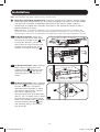 3
3
-
 4
4
-
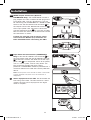 5
5
-
 6
6
-
 7
7
-
 8
8
-
 9
9
-
 10
10
-
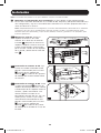 11
11
-
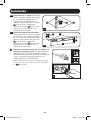 12
12
-
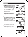 13
13
-
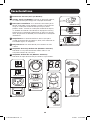 14
14
-
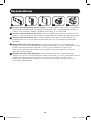 15
15
-
 16
16
-
 17
17
-
 18
18
-
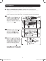 19
19
-
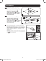 20
20
-
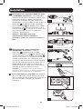 21
21
-
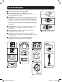 22
22
-
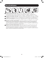 23
23
-
 24
24
-
 25
25
-
 26
26
-
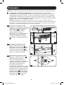 27
27
-
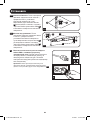 28
28
-
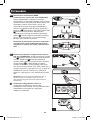 29
29
-
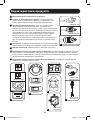 30
30
-
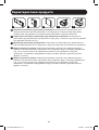 31
31
-
 32
32
-
 33
33
-
 34
34
-
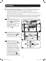 35
35
-
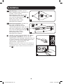 36
36
-
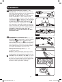 37
37
-
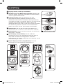 38
38
-
 39
39
-
 40
40


Tripp Lite Metered Rack PDU El manual del propietario
- Tipo
- El manual del propietario
- Este manual también es adecuado para
En otros idiomas
Documentos relacionados
-
Tripp Lite TRIPP-LITE 871814 Metered Rack PDU El manual del propietario
-
Tripp Lite PDUMH15-6 El manual del propietario
-
Tripp Lite Basic Rack PDU El manual del propietario
-
-
-
-
-
-
-