Detecto Physician's Scale El manual del propietario
- Tipo
- El manual del propietario

8525-0388-0M Rev A y Physician’s Scale Owner’s Manual
1
Physician’s Scale
Eye-Level Beam Scale
Owner’s Manual
Báscula médica
Báscula de brazo
a la altura de los ojos
Manual del propietario

8525-0388-0M Rev A y Physician’s Scale Owner’s Manual
2

8525-0388-0M Rev A y Physician’s Scale Owner’s Manual
1
INTRODUCTION
The Detecto Physician’s Eye-Level Beam Scale is ideal for use in health clinics and medical
practices for height and weight measurement. The scale is durable, having a sturdy
enameled steel scale base, removable slip-resistant plastic platform cover, a retractable
aluminum height rod, and rear wheels.
This manual is provided to guide you through the assembly and operation of your scale.
Please read it thoroughly before attempting to assemble or operate your scale and keep it
available for future reference.
This manual is for use with the following Physician’s Scales:
337 437 448 2371
338 438 449 2381
339 439 2391
349 2491
COPYRIGHT
All rights reserved. Reproduction or use, without expressed written permission, of editorial or
pictorial content, in any manner, is prohibited. No patent liability is assumed with respect to
the use of the information contained herein.
DISCLAIMER
While every precaution has been taken in the preparation of this manual, the Seller assumes
no responsibility for errors or omissions. Neither is any liability assumed for damages
resulting from the use of the information contained herein. All instructions and diagrams have
been checked for accuracy and ease of application; however, success and safety in working
with tools depend to a great extent upon individual accuracy, skill, and caution. For this
reason, the Seller is not able to guarantee the result of any procedure contained herein. Nor
can they assume responsibility for any damage to property or injury to persons occasioned
from the procedures. Persons engaging in the procedures do so entirely at their own risk.
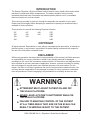
WARNING
x
ATTENDANT MUST ASSIST PATIENT ON AND OFF
THE SCALE PLATFORM.
x
NEVER LEAVE A PATIENT UNATTENDED WHILE ON
THE SCALE PLATFORM.
x
FAILURE TO MAINTAIN CONTROL OF THE PATIENT
AT ALL TIMES WHILE THEY ARE ON THE SCALE CAN
RESULT IN
SERIOUS INJURY TO THE PATIENT.

8525-0388-0M Rev A y Physician’s Scale Owner’s Manual
2
UNPACKING
Remove the scale base with platform cover, the column with weigh beam headpiece, height
measuring rod, wheel assembly, and hardware kit from the shipping carton. After removing
from the carton, check for any damage that may have occurred during shipment. Note that
the purchaser is responsible for filing all claims for any damages or loss incurred during
transit. Keep and use the original carton and packing material for return shipment if it should
become necessary.
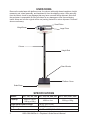
SPECIFICATIONS
Models: 337, 338, 339, 349 437, 438, 439, 448, 449 2371, 2381, 2391, 2491
Capacity:
440 lb x 4 oz or
200 kg x 100 g
450 lb x 4 oz 200 kg x 100 g
Height Measurement Range: 24-84” (60-212 cm)
Height Graduation: 0.125” (0.1 cm)
Platform Size: 14.75” x 10.75” (37.5 x 27.3 cm)
Column
Weigh Beam
Height Rod
Rear Wheels
Scale Base
Platform Cover
Large Poise
Small Poise

8525-0388-0M Rev A y Physician’s Scale Owner’s Manual
3
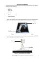
SCALE ASSEMBLY
The Detecto Physician’s Eye-Level Beam Scale comes partially assembled. The following
components require assembly:
x Column
x Draft Rod
x Height Rod
x Wheels
Tools required:
x Phillips head screwdriver
x Wrench (included)
1. Set the scale base on a table or other assembly area free from traffic and obstructions.
2. Remove the cable tie that secures the draft rod during transit (shown in Figure 1).
Figure 1. - Remove cable tie securing draft rod in column
3. Insert the column onto the scale base (shown in Figure 2), ensuring that the DETECTO
logo on the weight beam faces the scale base.
Figure 2. - Insert column onto scale base
Draft Rod
Cable Tie
Column
Scale Base

8525-0388-0M Rev A y Physician’s Scale Owner’s Manual
4
SCALE ASSEMBLY, CONT.
4. Using a Phillips screwdriver, install the eight screws and washers to secure the column to
the scale base as shown in Figure 3.
Figure 3. - Install eight screws and washers to secure the column to scale base
5. Lay the scale on a table. Remove and discard the shipping tie-wrap wires on the
underside of the scale base as shown in Figure 4.
Figure 4. - Lay scale on a table to access bottom of scale base

8525-0388-0M Rev A y Physician’s Scale Owner’s Manual
5
SCALE ASSEMBLY, CONT.
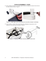
6. Insert the wrench (included) into the small hole in front of the draft rod and pull the draft
rod hook with the wrench to connect it to the long lever as shown in Figure 5. The draft
rod is located inside the scale column. Once the column is attached to the scale base, the
draft rod must be attached to the long lever.
Figure 5. - Connect draft rod hook to long lever
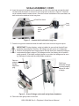
7. Push the long lever forward and hook the draft rod’s hook onto the long lever pivot.
IMPORTANT! During shipping, a plug is installed to ensure that the shelf lever
assembly stays aligned. However, the linkage may still come out of alignment.
Remove the plug and then visually ensure that the shelf lever assembly linkage is
centered and properly aligned. The linkage must be free-floating for the scale to
weigh properly. If the scale is slightly tipped to one side, the linkage can be seen
by looking up underneath the weigh beam headpiece.
Figure 6. - View of linkage underneath weigh beam headpiece
8. Place the scale gently back on the floor.
Draft Rod Hook
Long
Lever
Insert
wrench
here
Remove
shipping
linkage
alignment
plug
Shelf lever
assembly linkage
must be properly
aligned in order
to weigh

8525-0388-0M Rev A y Physician’s Scale Owner’s Manual
6
HEIGHT ROD INSTALLATION
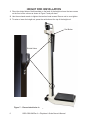
1. Place the slotted holes of both brackets on the back of the height rod over the two screws
on the front of the column as shown in Figure 7 and pull down.
2. Use the enclosed wrench to tighten the two hex-head screws. Be sure not to over-tighten.
3. To raise or lower the height rod, press the red button at the top of the height rod.
Figure 7. - Place slotted holes in height rod brackets over screws in column
Slotted Holes
Red Button

8525-0388-0M Rev A y Physician’s Scale Owner’s Manual
7
WHEEL ASSEMBLY INSTALLATION
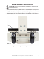
IMPORTANT! Mounting the wheel assembly upside down on the scale base will
cause weighing errors.
1. Align the mounting bracket of the wheel assembly to the scale base as shown in Figure 8.
2. Using the screws and washers that are included, attach the wheel assembly to the scale
base. Adjust the wheel assembly to a level position, and then tighten the screws.
3. When moving the scale, hold the column and tip the scale backward to keep the front of
the scale base away from the floor.
Figure 8. - Attaching wheel assembly to scale base
Bottom
Top

8525-0388-0M Rev A y Physician’s Scale Owner’s Manual
8
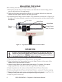
BALANCING THE SCALE
After assembly, the scale must be balanced before using it.
1. Ensure the scale is sitting on a level surface, and slide both the small and large poise to
zero (far-left position on the weigh beam).
2. Gently hold the beam pointer with your finger so it is centered within the trig loop area.
Release the beam pointer and let it rise freely up or down.
3. If the beam pointer doesn’t remain centered, turn the balance screw (shown in Figure 9) to
the right or left using a flathead screwdriver until the beam pointer remains centered within
the trig loop.
Figure 9. - Trig loop area and balance screw location
OPERATION
1. Place the scale on any hard, level, flat surface, or low-cut carpet.
2. Move both poise to the Zero position. Be sure the Beam Pointer is in the center of the
opening in the Trig Loop. Refer to Figure 9.
3. Slide the Large Poise to the approximate patient weight. For example, if the patient
weighs approximately 125 pounds, slide the Large Poise to 100 pounds.
4. Assist the patient onto the scale, and then slide the Small Poise to 20 pounds.
5. Continue sliding the Small Poise until the Beam Pointer is centered in Trig Loop opening.
6. Read the Small Poise at the pointer and add to the 100 pounds from the Large Poise. For
example, if the pointer is at 23 pounds, the patient weighs 123 pounds.
7. Assist the patient off the scale.
ALWAYS assist the patient when stepping on and off the scale platform to
ensure they do not fall. NEVER leave a patient unattended while they are
on the scale platform. Failure to maintain control of the patient at all times
can result in serious injury to the patient and/or you.
Small Poise
Large Poise
Weigh Beam
Balance
Screw
Beam Pointer
Trig Loop

8525-0388-0M Rev A y Physician’s Scale Owner’s Manual
9
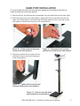
HAND POST INSTALLATION
For scale models that come with the hand post, please use the following instructions to
install the hand post to the scale platform.
1. Remove the four hex head screws and washers from the scale base and set them aside.
2. Place the hand post on the scale platform, aligning the holes in the hand post with the
holes in the scale platform, and then install and finger-tighten the four hex head screws
and washers to attach the hand post to the scale platform.
3. Using the provided wrench, tighten all four
hex head screws to secure the hand post
to the scale platform.
Figure 10. - Remove the four hex head
screws from scale platform
Figure 11. - Place hand post on scale
platform and install screws and washers
Figure 12. - Tighten all hex head screws
to secure hand post to scale platform
Figure 13. - View of scale with hand
post installed on scale platform

8525-0388-0M Rev A y Physician’s Scale Owner’s Manual
10
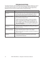
TROUBLESHOOTING
The Detecto Physician’s Eye-Level Beam Scale is factory-calibrated to within plus or minus
1/4 pound (0.1 kg) accuracy. For the most accurate readings, always use the scale on a
hard, level surface and stand in the center of the scale platform with the weight evenly
distributed. If an error occurs or seems excessive, check the following:
Problem Possible Solution
Zero balance out of
adjustment
x The weighing beam must be balanced so the beam pointer
comes to rest in the center of the trig loop when both the small
and large poise are set at zero (far-left position). Refer to
Figure 9 and the BALANCING THE SCALE instructions.
Beam does not move
freely
x Make sure the beam pointer is not touching the side of the trig
loop, impeding its range of travel.
x Visually ensure that the linkage is centered and properly
aligned. Occasionally during shipping, the alignment will
become skewed. The linkage must be free-floating for the
scale to weigh properly. If the scale is slightly tipped to one
side, the linkage can be seen by looking up underneath the
weigh beam headpiece.
Platform rocks
excessively
x Ensure the scale is sitting on a level surface. When you push
down on any corner of the platform, you should not feel any
significant rocking.
Beam does not move
at all during weighing
x Small and large poise is set higher than the person’s actual
weight. Reset both poise to a lower or zero weight.
x Make sure the draft rod is properly connected and aligned as
shown in Figure 5.
Scale is out of
calibration
x Recalibrate the scale by placing a known weight on the scale
and turning the balance screw until the pointer remains
centered within the trig loop.

8525-0388-0M Rev A y Physician’s Scale Owner’s Manual
11
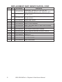
REPLACEMENT PART IDENTIFICATION

8525-0388-0M Rev A y Physician’s Scale Owner’s Manual
12
REPLACEMENT PART IDENTIFICATION, CONT.
Item Qty. Part Number Description
1
1 0033-0535-0A
BEAM ASSY, MODELS 337, 338, 339, 349
DUAL READING 440 LB X 4 OZ / 200 KG X 100 G
1 0033-0536-0A
BEAM ASSY, MODELS 437, 438, 439, 448, 449
450 LB X 4 OZ
1 0033-0537-0A
BEAM ASSY, MODELS 2371, 2381, 2391, 2491
200 KG X 100 G
2
1
0033-0538-08 BEAM YOKE COVER
3
1
0033-0539-0A BEAM YOKE ASSY
4
1
0033-0540-08 SHELF LEVER HANGER
5
1
0033-0541-0A DRAFT ROD AND SHELF LEVER LONG COLUMN
6
1
0033-0542-0A HEIGHT ROD
7 1 0033-0543-08 PLATFORM COVER LONG COLUMN
8
1
0033-0574-0A PLATFORM AND BEARING WITHOUT HOLES
9
1
0033-0545-0A WHEEL KIT
10
1
0033-0546-08 BASE FEET
11
1
0033-0547-08 HANGER OUTER
12
1
0033-0548-08 HANGER CENTER
13
1
0033-0549-08 DRAFTROD HOOK

8525-0388-0M Rev A y Physician’s Scale Owner’s Manual
13
STATEMENT OF LIMITED WARRANTY
Detecto Scale warrants its equipment to be free from defects in
material and workmanship as follows: Detecto warrants to the
original purchaser only that it will repair or replace any part of
equipment which is defective in material or workmanship for a
period of two (2) years from date of shipment. Detecto shall be
the sole judge of what constitutes a defect.
During the first ninety (90) days Detecto may choose to
replace the product at no charge to the buyer upon inspection of
the returned item.
After the first ninety (90) days, upon inspection of the returned
item, Detecto will repair or replace it with a remanufactured
product. The customer is responsible for paying for the freight
both ways.
This warranty does not apply to peripheral equipment not
manufactured by Detecto; this equipment will be covered by
certain manufacturer’s warranty only.
This warranty does not include replacement of expendable or
consumable parts. This does not apply to any item which has
deteriorated or damaged due to wear, accident, misuse, abuse,
improper line voltage, overloading, theft, lightning, fire, water or
acts of God, or due to extended storage or exposure while in
purchaser’s possession. This warranty does not apply to
maintenance service. Purchased parts will have a ninety (90)
day repair or replacement warranty only.
Detecto may require the suspect product to be returned to the
factory; item(s) must be properly packed and shipping charges
prepaid. A return authorization number must be obtained for all
returns and marked on the outside of all returned packages.
Detecto accepts no responsibility for loss or damage in transit.

8525-0388-0M Rev A y Physician’s Scale Owner’s Manual
14
STATEMENT OF LIMITED WARRANTY
Conditions Which Void Limited Warranty
This warranty shall not apply to equipment which:
A.) Has been tampered with, defaced, mishandled or has had
repairs and modifications not authorized by Detecto.
B.) Has had serial number altered, defaced, or removed.
C.) Has not been grounded according to Detecto’s
recommended procedure.
Freight Carrier Damage
Claims for equipment damaged in transit must be referred to the
freight carrier in accordance with freight carrier regulations.
This warranty sets forth the extent of our liability for breach of
any warranty or deficiency in connection with the sale or use of
the product. Detecto will not be liable for consequential damages
of any nature, including but not limited to, loss of profit, delays or
expenses, whether based on tort or contract. Detecto reserves
the right to incorporate improvements in material and design
without notice and is not obligated to incorporate improvements
in equipment previously manufactured.
The foregoing is in lieu of all other warranties, express or implied
including any warranty that extends beyond the description of
the product including any warranty of merchantability or fitness
for a particular purpose. This warranty covers only those Detecto
products installed in the forty-eight (48) contiguous continental
United States.
Ph. (800) 641-2008
E-mail: detecto@cardet.com
203 E. Daugherty
Webb City, MO 64870
08/27/2014
Printed in USA
D268-WARRANTY-DET-A

8525-0388-0M Rev A y Physician’s Scale Owner’s Manual
1
INTRODUCCIÓN
La báscula médica de brazo a la altura de los ojos de Detecto es ideal para usar en clínicas
de salud y prácticas médicas para medir la altura y el peso. La báscula es duradera, tiene
una base de báscula sólida de acero esmaltado, una cubierta de plataforma de plástico
antideslizante extraíble, una varilla retráctil de aluminio y ruedas traseras.
Este manual se proporciona para guiarlo a través del ensamblaje y para el funcionamiento
de su báscula. Léalo detenidamente antes de intentar ensamblar o poner a funcionar su
báscula y mantenerla disponible para referencia en un futuro.
Este manual es para usarlo con las siguientes básculas médicas:
337 437 448 2371
338 438 449 2381
339 439 2391
349 2491
DERECHOS DE AUTOR
Todos los derechos reservados. Se prohíbe la reproducción o el uso, sin permiso expreso
por escrito, de contenido editorial o pictórico, de cualquier manera. No se asume ninguna
responsabilidad de patente con respecto al uso de la información aquí contenida.
DESCARGO DE RESPONSABILIDAD
Mientras que todas las precauciones sean tomadas en la preparación de este manual, el
vendedor no asume ninguna responsabilidad por errores u omisiones. Tampoco se asume
ninguna responsabilidad por daños resultantes del uso de la información aquí contenida.
Todas las instrucciones y diagramas han sido verificados por su precisión y facilidad de
aplicación; sin embargo, el éxito y la seguridad en el trabajo con herramientas dependen en
gran medida de la precisión, habilidad y precaución individuales. Por esta razón, el vendedor
no puede garantizar el resultado de ningún procedimiento contenido en este documento.
Tampoco pueden asumir responsabilidad por daños a la propiedad o lesiones a personas
ocasionadas por los procedimientos. Las personas que participan en los procedimientos lo
hacen bajo su propio riesgo.
ADVERTENCIA
x
EL ENCARGADO DEBE AYUDAR AL PACIENTE DENTRO Y
FUERA DE LA PLATAFORMA DE BÁSCULA.
x
NUNCA DEJE A UN PACIENTE DESATENDIDO MIENTRAS
SE ENCUENTRA EN LA PLATAFORMA DE BÁSCULA.
x
NO MANTENER EL CONTROL DEL PACIENTE EN TODO
MOMENTO MIENTRAS ESTÁN EN LA BÁSCULA PUEDE
RESULTAR EN LESIONES GRAVES AL PACIENTE.
8525-0388-0M Rev A y Báscula médica Manual del propietario

8525-0388-0M Rev A y Physician’s Scale Owner’s Manual
2
DESEMPAQUE
Retire la base de la báscula con la cubierta de la plataforma, la columna con el cabezal de la
viga de pesaje, la varilla de medición de altura, el ensamblaje de la rueda y el kit de
hardware de la caja de envío. Después de sacarlo de la caja, verifique cualquier daño que
pueda haber ocurrido durante el envío. Tenga en cuenta que el comprador es responsable
de presentar todos los reclamos por cualquier daño o pérdida incurrida durante el tránsito.
Guarde y use la caja original y el material de desempaque para el envío de devolución si
fuera necesario.
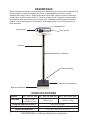
ESPECIFICACIONES
Modelos: 337, 338, 339, 349 437, 438, 439, 448, 449 2371, 2381, 2391, 2491
Capacidad:
200 kg x 100 g
or 440 lb x 4 oz
450 lb x 4 oz 200 kg x 100 g
Rango de medición de altura 60-212 cm (24-84”)
Graduación de altura 0.1 cm (0.125”)
Tamaño de plataforma 37.5 x 27.3 cm (14.75” x 10.75”)
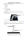
Base de la báscula
Cubierta de la plataforma
Ruedas traseras
Tallímetro
Columna
Viga de peso
Pesa grande
Pesa pequeña
8525-0388-0M Rev A y Báscula médica Manual del propietario

8525-0388-0M Rev A y Physician’s Scale Owner’s Manual
3
ENSAMBLADO DE LA BÁSCULA
La báscula médica de brazo a la altura de los ojos viene parcialmente ensamblada. Los
siguientes componentes requieren montaje:
x Columna
x Varilla de tiro
x Tallímetro
x Ruedas
Herramientas necesarias:
x Destornillador Phillips
x Llave inglesa (incluida)
1. Coloque la base de la báscula en una mesa u otra área libre de movimiento y
obstrucciones.
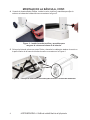
2. Retire la atadura de cables que asegura la varilla de tiro durante el tránsito (como se
muestra en la Figura 1.).
Figura 1. - Retire la atadura de cable que sujeta la varilla de tiro en la columna
3. Inserte la columna en la base de la báscula (que se muestra en la Figura 2),
asegurándose de que el logotipo DETECTO en la viga de peso mire hacia la base de la
báscula.
Figura 2. - Inserte la columna en la base de la báscula
Atadura de cable
Varilla de tiro
Columna
Base de la báscula
8525-0388-0M Rev A y Báscula médica Manual del propietario

8525-0388-0M Rev A y Physician’s Scale Owner’s Manual
4
MONTAJE DE LA BÁSCULA, CONT.
4. Usando el desatornillador Phillips, instale los ocho tornillos y arandelas para fijar la
columna a la base de la báscula como muestra en la figura 3.
Figura 3. - Instale los ocho tornillos y arandelas para
asegurar la columna a la base de la báscula.
5. Coloque la báscula sobre una mesa. Retire y deseche los cables de atadura de envío en
la parte inferior de la base de la báscula como se muestra en la Figura 4.
Figura 4. - Coloque la báscula en una mesa para acceder a la base de la báscula
8525-0388-0M Rev A y Báscula médica Manual del propietario

8525-0388-0M Rev A y Physician’s Scale Owner’s Manual
5
MONTAJE DE LA BÁSCULA, CONT.
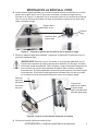
6. Inserte la llave inglesa (incluida) en el orificio pequeño frente a la varilla de tiro y tire del
gancho de la varilla de tiro con la llave para conectarla a la palanca larga como se
muestra en la Figura 5. La barra de tiro se encuentra dentro de la columna de la báscula.
Una vez que la columna está unida a la base de la báscula, la barra de tiro debe estar
unida a la palanca larga.
Figura 5. - Conecte el gancho de la varilla de tiro a la palanca larga.
7. Empuje la palanca larga hacia adelante y enganche el gancho de la varilla de tiro en el
pivote de la palanca larga.
¡IMPORTANTE! Durante el envío, se instala un enchufe para garantizar que el
conjunto de la palanca del estante permanezca alineado, sin embargo, el enlace
aún puede quedar desalineado. Retire el tapón y luego visualmente asegúrese de
que el enlace del conjunto de la palanca del estante esté centrado y alineado
correctamente. El enlace debe estar flotando libremente para que la báscula pese
correctamente. Si la báscula está ligeramente inclinada hacia un lado, se puede
ver el enlace mirando hacia arriba debajo del casco de la viga de pesaje.
Figura 6. Vista de la vinculación debajo de la cubierta
8. Coloque la báscula dócilmente sobre el piso.
Gancho de la
varilla de tiro
Palanca
larga
Inserte la llave
inglesa aqui
Retire el
tapón de
alineación
de enlace
de envío
Conjunto de
palanca de estante
el enlace debe
estar correctamente
alineado para pesar
8525-0388-0M Rev A y Báscula médica Manual del propietario

8525-0388-0M Rev A y Physician’s Scale Owner’s Manual
6
INSTALACIÓN DEL TALLIMETRO
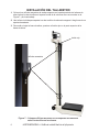
1. Coloque los orificios ranurados de ambos soportes en la parte posterior de la barra de
altura sobre los dos tornillos en la parte frontal de la columna como se muestra en la
Figura 7 y tire hacia abajo.
2. Use la llave incluida para apretar los dos tornillos de cabeza hexagonal. Asegúrese de no
apretar demasiado.
3. Para subir o bajar la barra de altura, presione el botón rojo en la parte superior de la
barra de altura.
Figura 7. - Coloque orificios ranurados en los soportes del tallímetro
sobre los tornillos en la columna
botón rojo
orificios ranurados
8525-0388-0M Rev A y Báscula médica Manual del propietario

8525-0388-0M Rev A y Physician’s Scale Owner’s Manual
7
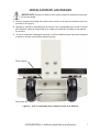
INSTALACION DE LAS RUEDAS
¡IMPORTANTE! Colocar la rueda al revés sobre la base de la báscula provocará
errores de pesaje.
1. Alinee el soporte de montaje del conjunto de la rueda con la base de la báscula como se
muestra en la Figura 8.
2. Usando los tornillos y arandelas que se incluyen, fije el ensamblaje de la rueda a la base
de la báscula. Ajuste el ensamblaje de la rueda a una posición nivelada y luego apriete
los tornillos.
3. Al mover la báscula, sostenga la columna e incline la báscula hacia atrás para mantener
el frente de la base de la báscula alejado del piso.
Figura 8. - Una el ensamblaje de la rueda a la base de la báscula
Parte superior
Parte baja
8525-0388-0M Rev A y Báscula médica Manual del propietario

8525-0388-0M Rev A y Physician’s Scale Owner’s Manual
8
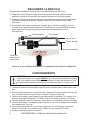
EQUILIBRAR LA BÁSCULA
Después del ensamblaje, la báscula debe estar equilibrada antes de su uso.
1. Asegúrese de que la báscula esté sobre una superficie nivelada y deslice la pesa
pequeña y grande a cero (posición del extremo izquierdo en la barra de pesaje).
2. Sostenga suavemente el puntero de viga con su dedo para que quede centrado dentro
del área del bucle trigonométrico. Suelte el puntero de viga y déjelo subir o bajar
libremente.
3. Si el puntero de la viga no permanece centrado, gire el tornillo de equilibrio (que se
muestra en la Figura 9) hacia la derecha o la izquierda con un destornillador de punta
plana hasta que el puntero de la viga permanezca centrado dentro del bucle
trigonométrico.
Figura 9. El área de bucle de activación y la ubicación del tronillo de calibración
FUNCIONAMIENTO
1. Coloque la báscula sobre cualquier superficie dura, nivelada, plana o alfombra de corte
bajo.
2. Mueva ambos contrapesos a la posición cero. Asegúrese de que el puntero de haz esté
en el centro de la abertura en el bucle de disparo. Consulte la Figura 9.
3. Deslice el contrapeso grande hasta el peso aproximado del paciente. Por ejemplo, si el
paciente pesa aproximadamente 125 libras, deslice el contrapeso grande a 100 libras.
4. Ayude al paciente a subir a la báscula y luego deslice el contrapeso pequeño a 20 libras.
5. Continúe deslizando el contrapeso pequeño hasta que el buce de disparo esté centrado
en la abertura del Trig Loop.
6. Lea el contrapeso pequeño en el puntero y agregue a las 100 libras del contrapeso
grande. Por ejemplo, si el puntero pesa 23 libras, el paciente pesa 123 libras.
7. Ayude al paciente a bajar de la báscula.
8525-0388-0M Rev A y Báscula médica Manual del propietario
SIEMPRE ayude al paciente al subir y bajar de la plataforma de la báscula para
asegurarse de que no se caiga. NUNCA deje a un paciente desatendido mientras
esté en la plataforma de la báscula. No mantener el control del paciente en todo
momento puede resultar en lesiones graves para el paciente y / o para usted.
Pesa grande
Pesa pequeña
Puntero de Viga
Viga de peso
Tornillo de
calibración la
bascule-tara
Bucle trigonométrico

8525-0388-0M Rev A y Physician’s Scale Owner’s Manual
9
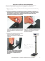
INSTALACIÓN DE APOYAMANOS
Para los modelos de báscula que vienen con el apoyamanos, utilice las siguientes
instrucciones para instalar el apoyamanos en la plataforma de la báscula.
1. Retire los cuatro tornillos y arandelas de cabeza hexagonal de la base de la báscula y
déjelos a un lado.
2. Coloque el apoyamanos en la plataforma de la báscula, alineando los agujeros en el
apoyamanos con los agujeros en la plataforma de la báscula, y luego instale y apriete
con los dedos los cuatro tornillos y arandelas de cabeza hexagonal para fijar el
apoyamanos a la plataforma de la báscula.
3. Usando la llave provista, apriete los cuatro
tornillos de cabeza hexagonal para
asegurar el apoyamanos a la plataforma de
la báscula.
Figura 11. - Coloque el apoyamanos en
la plataforma de la báscula e instale
tornillos y arandelas
Figura 10. - Retire los cuatro tornillos de
cabeza hexagonal de la plataforma de la
báscula
Figura 13. - Vista de la
báscula con apoyamanos
instalado en la plataforma
de la báscula
Figura 12. - Apriete todos los tornillos
de cabeza hexagonal para asegurar el
apoyamanos a la plataforma de la
báscula.
8525-0388-0M Rev A y Báscula médica Manual del propietario

8525-0388-0M Rev A y Physician’s Scale Owner’s Manual
10
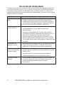
SOLUCIÓN DE PROBLEMAS
La bascula medica de brazo a la altura de los ojos de Detecto está calibrada de fábrica con
una precisión de más o menos 0.1 kg (1/4 libras). Para obtener las lecturas más precisas,
use siempre la báscula sobre una superficie dura y nivelada y párese en el centro de la
plataforma de la báscula con el peso distribuido uniformemente. Si ocurre un error o parece
excesivo, verifique lo siguiente:
Problema Posibles soluciones.
Equilibrio cero fuera de
ajuste
x La viga de pesaje debe estar equilibrada para que el puntero
de viga se detenga en el centro del bucle trigonométrico
cuando tanto la pesa pequeña como la grande se ajustan a
cero (posición del extremo izquierdo). Consulte la Figura 9 y
las instrucciones para EQUILIBRAR LA BASCULA.
La viga de peso no se
mueve libremente
x Asegúrese de que el puntero de viga no toque el lado del
bucle trigonométrico, lo que impide su alcance de
desplazamiento.
x Asegúrese visualmente de que el enlace esté centrado y
correctamente alineado. Ocasionalmente durante el envío, la
alineación se sesgará. El enlace debe estar flotando
libremente para que la báscula pese correctamente. Si la
báscula está ligeramente inclinada hacia un lado, se puede
ver el enlace mirando hacia arriba debajo del casco de la viga
de pesaje.
La plataforma se
balancea en exeso
x Asegurese de que la bascula este en una superficie nivelada.
Cuando empuje havcia abajo en cualquer esquina de la
plataforma, no debe sentir ningun balanceo significativo.
La viga de peso no se
mueve en lo absoluto
durante el pesaje
x El equilibrio pequeño y grande se ajusta más alto que el peso
real de la persona. Restablezca los dos equilibrios a un peso
inferior o cero.
x Asegúrese de que la varilla de tiro esté correctamente
conectada y alineada como se muestra en la Figura 5.
La bascula no esta
calibrada
x Vuelva a calibrar la báscula colocando un peso conocido en
la báscula y girando el tornillo de equilibrio hasta que el
puntero permanezca centrado dentro del bucle
trigonométrico.
8525-0388-0M Rev A y Báscula médica Manual del propietario

8525-0388-0M Rev A y Physician’s Scale Owner’s Manual
11
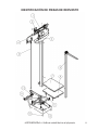
IDENTIFICACIÓN DE PIEZAS DE REPUESTO
8525-0388-0M Rev A y Báscula médica Manual del propietario

8525-0388-0M Rev A y Physician’s Scale Owner’s Manual
12
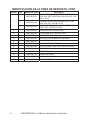
IDENTIFICACIÓN DE LA PIEZA DE REPUESTO, CONT.
Artículo Cant. Número de pieza Descripción
1
1 0033-0535-0A
CONJUNTO DE VIGAS, MODELOS 337, 338,
339, 349 - LECTURA DUAL 440 LB X 4 OZ / 200
KG X 100 G
1 0033-0536-0A
CONJUNTO DE VIGAS, MODELOS 437, 438,
439, 448, 449 - 450 LB X 4 OZ
1 0033-0537-0A
CONJUNTO DE VIGAS, MODELOS 2371, 2381,
2391, 2491 - 200 KG X 100 G
2
1
0033-0538-08
COVERTOR DE VIGA DEL YUGO
3
1
0033-0539-0A
COMPONENTE DE VIGA DEL YUGO
4
1
0033-0540-08
GANCHO DE PALANCA
5
1
0033-0541-0A PROYECTOR DE BARRA Y PALANCA
6
1
0033-0542-0A
TALLIMETRO
7 1 0033-0543-08
COVERTOR DE PLATAFORMA
8
1
0033-0574-0A PLATAFORMA Y SOPORTE SIN AGUJEROS
9
1
0033-0545-0A
EQUIPO DE LLANTAS
10
1
0033-0546-08
PATA BASE
11
1
0033-0547-08
GANCH EXTERNO
12
1
0033-0548-08
GANCHO COLGANTE
13
1
0033-0549-08
GANCHO DE TIRO
8525-0388-0M Rev A y Báscula médica Manual del propietario

8525-0388-0M Rev A y Physician’s Scale Owner’s Manual
13
DECLARACIÓN DE GARANTÍA LIMITADA
Detecto Scale garantiza que su equipo está libre de defectos de
material y mano de obra de acuerdo con lo siguiente: Detecto
garantiza al comprador original, solamente, que reparará o
reemplazará cualquier parte del equipo que esté defectuosa, en
cuanto a material o mano de obra se refiere, por un periodo de dos
(2) años a partir de la fecha de envío. Detecto será el único juez
que dicte que es lo que constituye un defecto.
Durante los primeros noventa (90) días Detecto puede elegir
reemplazar el producto sin ningún cargo para el comprador ante la
inspección del ítem devuelto.
Después de los primeros noventa (90) días, ante la inspección
del ítem devuelto, Detecto lo reparará o reemplazará con un
producto refabricado. El cliente será responsable de pagar el
transporte de ida y vuelta.
Esta garantía no aplica a equipo periférico no fabricado por Detecto;
este equipo será cubierto por cierta garantía de fabricante
únicamente.
Esta garantía no incluye reemplazo de partes desechables o
consumibles. Lo anterior no aplica a ningún ítem que se haya
deteriorado o dañado debido al uso diario, accidente, mal uso,
abuso, línea de voltaje inadecuada, sobrecarga, robo, relámpago,
fuego, agua o caso fortuito, o debido a almacenaje o exposición
prolongadas en posesión del comprador. Esta garantía no aplica a
servicio de mantenimiento. Las partes compradas contarán con una
garantía de reparación o reemplazo de noventa (90) días
únicamente.
Detecto podrá solicitar que el producto sean devuelto a la fábrica;
los ítems deberán estar empacados adecuadamente y los cargos de
envío deben estar prepagados. Se deberá obtener un número de
autorización de devolución para todas las devoluciones y deberá
aparecer en la parte externa de todos los paquetes. Detecto no
acepta responsabilidad alguna por pérdida o daño durante el
traslado.
8525-0388-0M Rev A y Báscula médica Manual del propietario

8525-0388-0M Rev A y Physician’s Scale Owner’s Manual
14
DECLARACIÓN DE GARANTÍA LIMITADA
Condiciones que Invalidan la Garantía Limitada
Esta garantía no aplicará al equipo que:
A
.) Haya sido manipulado, desfigurado, manejado incorrectamente
o haya sido reparado o modificado sin autorización por parte de
Detecto.
B.) Se haya alterado, desfigurado o retirado el número de serie.
C.) No haya sido aterrizado de acuerdo con el proceso
recomendado por Detecto.
Daño de Transporte
Los reclamos por equipo dañado durante traslado deberán ser
dirigidos al transportista, de acuerdo con las regulaciones del
transportista.
Esta garantía establece el alcance de nuestra responsabilidad para
incumplimiento de cualquier garantía o deficiencia en relación con la
venta o uso del producto. Detecto no será responsable por daños
consecuentes de naturaleza alguna, incluyendo, entre otros, lucro
cesante, retrasos o gastos, ya sean basados en responsabilidad
extra-contractual o contractual. Detecto se reserva el derecho a
incorporar mejoras en materiales y diseño sin aviso previo y no está
obligado a incorporar dichas mejoras a equipo fabricado
previamente.
Lo anterior sustituye cualquier otra garantía, expresa o implícita,
incluyendo cualquier garantía que vaya más allá de la descripción
del producto, incluyendo cualquier garantía de comerciabilidad o
adecuación para un propósito particular. Esta garantía cubre
únicamente aquellos productos Detecto instalados en los cuarenta y
ocho (48) estados contiguos de los Estados Unidos de América.
Tel. (800) 641-2008
E-mail: detecto@cardet.com
203 E. Daugherty
Webb City, MO 64870
08/27/2014
Impreso en EUA
D268-WARRANTY-DET
8525-0388-0M Rev A y Báscula médica Manual del propietario

8525-0388-0M Rev A y Physician’s Scale Owner’s Manual
15

8525-0388-0M Rev A y Physician’s Scale Owner’s Manual
16
Cardinal Scale Manufacturing Co.
102 E. Daugherty, Webb City, MO 64870 USA
Ph: 417-673-4631 or 1-800-641-2008
Fax: 417-673-2153
Technical Support: 1-866-254-8261
E-mail: tech@cardet.com
8525-0388-0M Rev A 03/21
-
 1
1
-
 2
2
-
 3
3
-
 4
4
-
 5
5
-
 6
6
-
 7
7
-
 8
8
-
 9
9
-
 10
10
-
 11
11
-
 12
12
-
 13
13
-
 14
14
-
 15
15
-
 16
16
-
 17
17
-
 18
18
-
 19
19
-
 20
20
-
 21
21
-
 22
22
-
 23
23
-
 24
24
-
 25
25
-
 26
26
-
 27
27
-
 28
28
-
 29
29
-
 30
30
-
 31
31
-
 32
32


Detecto Physician's Scale El manual del propietario
- Tipo
- El manual del propietario
En otros idiomas
Documentos relacionados
-
Detecto Physician's Scale El manual del propietario
-
-
-
-
-
-
-
-
-