GE Profile PP9830DJBB Guía de instalación
- Tipo
- Guía de instalación

49-80635-1 03-15 GE
GEAppliances.com
Safety Information ............2
Warranty ........................4
Assistance /
Parts and Accessories .........5
Using The Cooktop
Cooktop Features ..................6
Surface Burners ....................7
Cookware for Radiant
Glass Cooktop ....................9
For Best Results ....................9
Care and Cleaning
Cleaning The Cooktop .............10
Cleaning the Glass Cooktop ........11
Installation Instructions ......13
Troubleshooting Tips .........25
Cooktop
Radiant Downdraft
Write the model and serial
numbers here:
Model # ______________________
Serial # _______________________
Find these numbers on a label
under the cooktop, on the side
of the vent chamber.
For a Spanish version of this
manual, visit our Website at
GEAppliances.com.
Para consultar una version
en español de este manual
de instrucciones, visite
nuestro sitio de internet
GEAppliances.com.
Owner’s Manual &
Installation Instructions
PP9830

2
49-80635-1
SAVE THESE INSTRUCTIONS
Read all safety instructions before using the product. Failure to follow these
instructions may result in fire, electric shock, serious injury or death.
WARNING
IMPORTANT SAFETY INFORMATION.
READ ALL INSTRUCTIONS BEFORE USING.
SAFETY INFORMATION
Ŷ 8VHWKLVDSSOLDQFHIRULWVLQWHQGHGSXUSRVHDV
described in this Owner’s Manual.
Ŷ %HVXUH\RXUDSSOLDQFHLVSURSHUO\LQVWDOOHGDQG
grounded by a qualified installer in accordance
with the provided installation instructions.
Ŷ 'RQRWDWWHPSWWRUHSDLURUUHSODFHDQ\SDUWRI
your range unless it is specifically recommended
in this manual. All other servicing should be
referred to a qualified technician.
Ŷ %HIRUHSHUIRUPLQJDQ\VHUYLFHXQSOXJWKH
cooktop or disconnect the power supply at the
household distribution panel by removing the
fuse or switching off the circuit breaker.
Ŷ 'RQRWOHDYHFKLOGUHQDORQH²FKLOGUHQVKRXOG
not be left alone or unattended in an area where
an appliance is in use. They should never be
allowed to climb, sit or stand on any part of the
appliance.
Ŷ
CAUTION:'RQRWVWRUHLWHPVRILQWHUHVW
WRFKLOGUHQDERYHDFRRNWRS²FKLOGUHQFOLPELQJ
on the cooktop to reach items could be seriously
injured.
Ŷ 8VHRQO\GU\SRWKROGHUV²PRLVWRUGDPSSRW
holders on hot surfaces may result in burns from
VWHDP'RQRWOHWSRWKROGHUVWRXFKKRWVXUIDFH
XQLWVRUKHDWLQJHOHPHQWV'RQRWXVHDWRZHORU
other bulky cloth in place of pot holders.
Ŷ 1HYHUXVH\RXUDSSOLDQFHIRUZDUPLQJRUKHDWLQJ
the room.
Ŷ 'RQRWWRXFKWKHVXUIDFHHOHPHQWV7KHVH
surfaces may be hot enough to burn even though
WKH\DUHGDUNLQFRORU'XULQJDQGDIWHUXVH
do not touch, or let clothing or other flammable
materials contact the surface units or areas
nearby the surface units; allow sufficient time for
cooling first. Other surfaces of the appliance may
become hot enough to cause burns. Potentially
hot surfaces include the cooktop and areas
facing the cooktop.
Ŷ 'RQRWKHDWXQRSHQHGIRRGFRQWDLQHUV3UHVVXUH
could build up and the container could burst,
causing an injury.
Ŷ &RRNPHDWDQGSRXOWU\WKRURXJKO\²PHDWWR
at least an internal temperature of 160°F and
poultry to at least an internal temperature of
)&RRNLQJWRWKHVHWHPSHUDWXUHVXVXDOO\
protects against foodborne illness.
Ŷ 6XIILFLHQWDLULVQHHGHGIRUSURSHUFRPEXVWLRQDQG
exhausting of gases through the flue (chimney) of
fuel burning equipment to prevent back drafting.
Follow the heating equipment manufacturer’s
guide lines and safety standards, such as
WKRVHSXEOLVKHGE\WKH1DWLRQDO)LUH3URWHFWLRQ
$VVRFLDWLRQ1)3$WKH$PHULFDQ6RFLHW\IRU
+HDWLQJ5HIULJHUDWLRQDQG$LU&RQGLWLRQLQJ
$6+5$(DQGWKHORFDOFRGHDXWKRULWLHVZKHQ
applicable, install any make up (replacement)
air system in accordance with local building
FRGHUHTXLUHPHQWV9LVLW*($SSOLDQFHVFRPIRU
available makeup air solutions
Ŷ 'RQRWVWRUHRUXVHIODPPDEOHPDWHULDOQHDUWKH
cooktop, including paper, plastic, pot holders,
linens, wall coverings, curtains, drapes and
gasoline or other flammable vapors and liquids.
Ŷ1HYHUZHDUORRVHILWWLQJRUKDQJLQJJDUPHQWVZKLOH
using the appliance. These garments may ignite if
they contact hot surfaces causing severe burns.
Ŷ'RQRWOHWFRRNLQJJUHDVHRURWKHUIODPPDEOH
materials accumulate on or near the cooktop.
Grease on the cooktop may ignite.
Ŷ&OHDQYHQWLODWLQJKRRGVIUHTXHQWO\*UHDVHVKRXOG
not be allowed to accumulate on the hood or filter.
GENERAL SAFETY INSTRUCTIONS
KEEP FLAMMABLE MATERIALS AWAY FROM
THE COOKTOP.
WARNING
WARNING

49-80635-1
3
SAVE THESE INSTRUCTIONS
SAFETY INFORMATION
Ŷ 1HYHUOHDYHWKHVXUIDFHXQLWVXQDWWHQGHGDWPHGLXP
RUKLJKKHDWVHWWLQJV%RLORYHUVFDXVHVPRNLQJDQG
greasy spillovers that may catch on fire.
Ŷ 1HYHUOHDYHRLOXQDWWHQGHGZKLOHIU\LQJ,IDOORZHG
to heat beyond its smoking point, oil may ignite
resulting in fire that may spread to surrounding
FDELQHWV8VHDGHHSIDWWKHUPRPHWHUZKHQHYHU
possible to monitor oil temperature.
Ŷ 7RDYRLGRLOVSLOORYHUDQGILUHXVHDPLQLPXP
DPRXQWRIRLOZKHQVKDOORZSDQIU\LQJDQGDYRLG
cooking frozen foods with excessive amounts of ice.
Ŷ 8VHSURSHUSDQVL]H²VHOHFWFRRNZDUHKDYLQJ
flat bottoms large enough to cover the surface
heating element. The use of undersized
cookware will expose a portion of the surface
unit to direct contact and may result in ignition
of clothing. Proper relationship of cookware to
surface unit will also improve efficiency.
Ŷ 2QO\FHUWDLQW\SHVRIJODVVJODVVFHUDPLF
earthenware or other glazed containers are
suitable for cooktop service; others may break
because of the sudden change in temperature.
Ŷ 7RPLQLPL]HWKHSRVVLELOLW\RIEXUQVLJQLWLRQRI
flammable materials and spillage, the handle of a
container should be turned toward the center of the
range without extending over nearby surface units.
Ŷ :KHQSUHSDULQJIODPLQJIRRGVXQGHUDKRRGWXUQ
the fan on.
Ŷ 8VHFDUHZKHQWRXFKLQJWKHFRRNWRS7KHJODVV
surface of the cooktop will retain heat after the
controls have been turned off.
Ŷ $YRLGVFUDWFKLQJRULPSDFWLQJWKHJODVVFRRNWRS
'RLQJVRPD\OHDGWREURNHQJODVV7KHFRRNWRS
can be scratched with items such as knives,
sharp instruments, rings or other jewelry, and
rivets on clothing.
Ŷ 'RQRWFRRNRQDEURNHQFRRNWRS,IJODVV
cooktop should break, cleaning solutions and
spillovers may penetrate the broken cooktop and
FUHDWHDULVNRIHOHFWULFVKRFN&RQWDFWDTXDOLILHG
technician immediately.
Ŷ 'RQRWSODFHRUVWRUHLWHPVWKDWFDQPHOWRUFDWFK
fire on the glass cooktop, even when it is not
EHLQJXVHG,IWKHFRRNWRSLVLQDGYHUWHQWO\WXUQHG
on, they may ignite. Heat from the cooktop after it
is turned off may cause them to ignite also.
Ŷ 8VH&(5$0$%5<7(
®
FHUDPLF&RRNWRS&OHDQHU
DQG&(5$0$%5<7(
®
&OHDQLQJ3DGWRFOHDQ
WKHFRRNWRS:DLWXQWLOWKHFRRNWRSFRROVDQG
the indicator light goes out before cleaning. A
wet sponge or cloth on a hot surface can cause
VWHDPEXUQV6RPHFOHDQHUVFDQSURGXFH
noxious fumes if applied to a hot surface.
127(6XJDUVSLOOVDUHDQH[FHSWLRQ7KH\
should be scraped off while still hot using an
RYHQPLWWDQGDVFUDSHU6HHWKH&OHDQLQJWKH
glass cooktop section for detailed instructions.
Ŷ 5HDGDQGIROORZDOOLQVWUXFWLRQVDQGZDUQLQJVRQ
the cleaning cream label.
Ŷ 'RQRWXVHZDWHURQJUHDVHILUHV1HYHUSLFNXS
DIODPLQJSDQ7XUQWKHFRQWUROVRII6PRWKHUD
flaming pan on a surface unit by covering the
SDQFRPSOHWHO\ZLWKDZHOOILWWLQJOLGFRRNLHVKHHW
RUIODWWUD\8VHDPXOWLSXUSRVHGU\FKHPLFDORU
IRDPW\SHILUHH[WLQJXLVKHU
RADIANT COOKTOP SAFETY INSTRUCTIONS
IN THE EVENT OF A FIRE, TAKE THE FOLLOWING
STEPS TO PREVENT THE FIRE FROM SPREADING:
WARNING
WARNING

4
49-80635-1
GE Radiant Cooktop Warranty
GEAppliances.com
$OOZDUUDQW\VHUYLFHLVSURYLGHGE\RXU)DFWRU\6HUYLFH&HQWHUVRUDQDXWKRUL]HG&XVWRPHU&DUH
®
technician.
7RVFKHGXOHVHUYLFHRQOLQHYLVLWXVDWZZZJHDSSOLDQFHVFRPVHUYLFHBDQGBVXSSRUWRUFDOO*(&$5(6
(800.432.2737). Please have serial number and model number available when calling for service.
6HUYLFLQJ\RXUDSSOLDQFHPD\UHTXLUHWKHXVHRIWKHRQERDUGGDWDSRUWIRUGLDJQRVWLFV7KLVJLYHVD*(IDFWRU\
VHUYLFHWHFKQLFLDQWKHDELOLW\WRTXLFNO\GLDJQRVHDQ\LVVXHVZLWK\RXUDSSOLDQFHDQGKHOSV*(LPSURYHLWVSURGXFWV
E\SURYLGLQJ*(ZLWKLQIRUPDWLRQRQ\RXUDSSOLDQFH,I\RXGRQRWZDQW\RXUDSSOLDQFHGDWDWREHVHQWWR*(SOHDVH
DGYLVH\RXUWHFKQLFLDQQRWWRVXEPLWWKHGDWDWR*(DWWKHWLPHRIVHUYLFH
)RUWKHSHULRGRIRQH\HDUIURPWKHGDWHRIWKHRULJLQDOSXUFKDVH*(ZLOOSURYLGHDQ\SDUWRIWKHFRRNWRSZKLFK
IDLOVGXHWRDGHIHFWLQPDWHULDOVRUZRUNPDQVKLS'XULQJWKLVOLPLWHGRQH\HDUZDUUDQW\*(ZLOODOVRSURYLGHIUHHRI
FKDUJHDOOODERUDQGLQKRPHVHUYLFHWRUHSODFHWKHGHIHFWLYHSDUW
What GE will not cover:
Ŷ 6HUYLFHWULSVWR\RXUKRPHWRWHDFK\RXKRZWRXVH
the product.
Ŷ ,PSURSHULQVWDOODWLRQGHOLYHU\RUPDLQWHQDQFH
Ŷ Failure of the product if it is abused, misused,
modified or used for other than the intended purpose
or used commercially.
Ŷ Replacement of house fuses or resetting of circuit
breakers.
Ŷ 'DPDJHWRWKHSURGXFWFDXVHGE\DFFLGHQWILUH
floods or acts of God.
Ŷ ,QFLGHQWDORUFRQVHTXHQWLDOGDPDJHFDXVHGE\
possible defects with this appliance.
Ŷ 'DPDJHFDXVHGDIWHUGHOLYHU\
Ŷ Product not accessible to provide required service.
Ŷ 6HUYLFHWRUHSDLURUUHSODFHOLJKWEXOEVH[FHSWIRU
/('ODPSV
Ŷ ,QVWDOODWLRQRUVHUYLFHIRUDPDNHXSUHSODFHPHQW
air system.
EXCLUSION OF IMPLIED WARRANTIES
<RXUVROHDQGH[FOXVLYHUHPHG\LVSURGXFWUHSDLUDVSURYLGHGLQWKLV/LPLWHG:DUUDQW\$Q\LPSOLHGZDUUDQWLHV
including the implied warranties of merchantability or fitness for a particular purpose, are limited to one year or the
shortest period allowed by law.
This warranty is extended to the original purchaser and any succeeding owner for products purchased for home use
ZLWKLQWKH86$,IWKHSURGXFWLVORFDWHGLQDQDUHDZKHUHVHUYLFHE\D*($XWKRUL]HG6HUYLFHULVQRWDYDLODEOH\RX
PD\EHUHVSRQVLEOHIRUDWULSFKDUJHRU\RXPD\EHUHTXLUHGWREULQJWKHSURGXFWWRDQ$XWKRUL]HG*(6HUYLFHORFDWLRQ
IRUVHUYLFH,Q$ODVNDWKHZDUUDQW\H[FOXGHVWKHFRVWRIVKLSSLQJRUVHUYLFHFDOOVWR\RXUKRPH
6RPHVWDWHVGRQRWDOORZWKHH[FOXVLRQRUOLPLWDWLRQRILQFLGHQWDORUFRQVHTXHQWLDOGDPDJHV7KLVZDUUDQW\JLYHV\RX
specific legal rights, and you may also have other rights which vary from state to state. To know what your legal rights
are, consult your local or state consumer affairs office or your state’s Attorney General.
Warrantor: General Electric Company. Louisville, KY 40225
Extended Warranties:3XUFKDVHD*(H[WHQGHGZDUUDQW\DQGOHDUQDERXWVSHFLDOGLVFRXQWVWKDWDUHDYDLODEOHZKLOH
\RXUZDUUDQW\LVVWLOOLQHIIHFW<RXFDQSXUFKDVHLWRQOLQHDQ\WLPH
ZZZJHDSSOLDQFHVFRPVHUYLFHBDQGBVXSSRUWVKRSIRUH[WHQGHGVHUYLFHSODQVKWP
RUFDOOGXULQJQRUPDOEXVLQHVVKRXUV*(&RQVXPHU+RPH6HUYLFHVZLOOVWLOOEHWKHUHDIWHU\RXU
warranty expires.
Register Your Appliance: 5HJLVWHU\RXUQHZDSSOLDQFHRQOLQHDW\RXUFRQYHQLHQFH
ZZZJHDSSOLDQFHVFRPVHUYLFHBDQGBVXSSRUWUHJLVWHU
Timely product registration will allow for enhanced communication and prompt service under the terms of your warranty,
VKRXOGWKHQHHGDULVH<RXPD\DOVRPDLOLQWKHSUHSULQWHGUHJLVWUDWLRQFDUGLQFOXGHGLQWKHSDFNLQJPDWHULDO
6WDSOH\RXUUHFHLSWKHUH3URRIRIWKHRULJLQDOSXUFKDVH
date is needed to obtain service under the warranty.
WARRANTY
Thank You! ... for your purchase of a GE Brand appliance.

49-80635-1
5
Schedule Service: ([SHUW*(UHSDLUVHUYLFHLVRQO\RQH
VWHSDZD\IURP\RXUGRRU*HWRQOLQHDQGVFKHGXOH\RXU
VHUYLFHDWZZZJHDSSOLDQFHVFRPVHUYLFHBDQGBVXSSRUW
2UFDOO*(&$5(6GXULQJQRUPDO
business hours.
Parts and Accessories: ,QGLYLGXDOVTXDOLILHGWRVHUYLFH
their own appliances can have parts or accessories sent
GLUHFWO\WRWKHLUKRPHV9,6$0DVWHU&DUGDQG'LVFRYHU
FDUGVDUHDFFHSWHG2UGHURQOLQHWRGD\KRXUV
every day or by phone at 800.626.2002 during normal
business hours.
,QVWUXFWLRQVFRQWDLQHGLQWKLVPDQXDOFRYHUSURFHGXUHV
to be performed by any user. Other servicing generally
VKRXOGEHUHIHUUHGWRTXDOLILHGVHUYLFHSHUVRQQHO&DXWLRQ
must be exercised, since improper servicing may cause
unsafe operation.
Real Life Design Studio: *(VXSSRUWVWKH8QLYHUVDO
'HVLJQFRQFHSWRISURGXFWVVHUYLFHVDQGHQYLURQPHQWV
that can be used by people of all ages, sizes and
FDSDELOLWLHV:HUHFRJQL]HWKHQHHGWRGHVLJQIRUDZLGH
range of physical and mental abilities and impairments.
)RUGHWDLOVRI*(¶V8QLYHUVDO'HVLJQDSSOLFDWLRQV
including kitchen design ideas for people with disabilities,
FKHFNRXWRXU:HEVLWHWRGD\)RUWKHKHDULQJLPSDLUHG
SOHDVHFDOO7''*($&
Contact Us: ,I\RXDUHQRWVDWLVILHGZLWKWKHVHUYLFH\RX
UHFHLYHIURP*(FRQWDFWXVRQRXU:HEVLWHZLWKDOOWKH
GHWDLOVLQFOXGLQJ\RXUSKRQHQXPEHURUZULWHWR
General Manager, Customer Relations
GE Appliances, Appliance Park Louisville, KY 40225
7U\WKH*($SSOLDQFHV:HEVLWHwww.geappliances.com/service_and_support/) 24 hours a day, any day of the
\HDU)RUJUHDWHUFRQYHQLHQFHDQGIDVWHUVHUYLFH\RXFDQQRZGRZQORDG2ZQHU¶V0DQXDOVRUGHUSDUWVRUHYHQ
VFKHGXOHVHUYLFHRQOLQH
Parts and Accessories
7RSODFHDQRUGHUYLVLWXVRQOLQHDW
www.GEApplianceParts.com86RUwww.GEAppliances.ca&DQDGD
or call 800.626.200286800.661.1616&DQDGD
7KHIROORZLQJSDUWVDUHDYDLODEOH
How to Remove Protective Shipping Film and Packaging Tape
&DUHIXOO\JUDVSDFRUQHURIWKHSURWHFWLYHVKLSSLQJILOP
with your fingers and slowly peel it from the appliance
VXUIDFH'RQRWXVHDQ\VKDUSLWHPVWRUHPRYHWKHILOP
Remove all of the film before using the appliance for the
first time.
To assure no damage is done to the finish of the
product, the safest way to remove the adhesive from
packaging tape on new appliances is an application of
a household liquid dishwashing detergent. Apply with a
soft cloth and allow to soak.
NOTE: 7KHDGKHVLYHPXVWEHUHPRYHGIURPDOOSDUWV,W
cannot be removed if it is baked on.
Parts
9HQW)LOWHU :%;
9HQW*ULOOH:KLWH :%;
9HQW*ULOOH%ODFN :%;
/RFNDQG9HQW&RQWURO.QRE:KLWH :%;
/RFNDQG9HQW&RQWURO.QRE%ODFN :%;
/RFNDQG9HQW&RQWURO.QRE66 :%;
%XUQHU&RQWURO.QRE:KLWH :%;
%XUQHU&RQWURO.QRE%ODFN :%;
%XUQHU&RQWURO.QRE66 :%7
Cleaning Supplies
&LWUX6KLQH6WDLQOHVV6WHHO:LSHV :;;
&(5$0$%5<7(
®
6WDLQOHVV6WHHO$SSOLDQFH&OHDQHU 30;
&(5$0$%5<7(
®
&OHDQLQJ3DGVIRU&HUDPLF&RRNWRSV :;;
&(5$0$%5<7(
®
&HUDPLF&RRNWRS&OHDQHU :;;
&(5$0$%5<7(
®
&HUDPLF&RRNWRS6FUDSHU :;;
.LW.LWLQFOXGHVFUHDPDQGFRRNWRSVFUDSHU :%;
Have a question or need assistance with your appliance?
ASSISTANCE / PARTS AND ACCESSORIES

6
49-80635-1
1. Left Rear Surface Unit
2. Bridge Surface Unit
3. Left Front Surface Unit
4. Vent Grille
5. Vent Filter (below the vent grille)
6. Right Rear Surface Unit
7. Dual Surface Unit
8. Model and Serial Number Label (under the
cooktop, on the right side of the vent chamber)
9. Left Rear Surface Unit Control
10. Left Front Surface Unit Control
11. Left Side Hot Surface Indicator Lights
(one for each surface unit)
12. Vent Fan Speed Control
13. Control Lock Knob
14. Right Side Hot Surface Indicator Lights
(one for each surface unit)
15. Dual Surface Unit Control
16. Right Rear Surface Unit Control
17. Surface Unit On Indicator Light
Throughout this manual, features and appearance may vary from your model.
Cooktop Features
USING THE COOKTOP: Cooktop Features
Feature Index (Features and appearance may vary)
4516
378
2
9
13
17
12
11
10 15
16
14

49-80635-1
7
Surface Burners
USING THE COOKTOP: Surface Burners
Radiant Surface Units
The control for the radiant surface unit can be set
anywhere between LO and HI for an unlimited number
RIKHDWVHWWLQJV:LWKWKHLQILQLWHVZLWFKWKHFRLOF\FOHVRQ
and off to maintain your selected control setting.
To bring liquids to a boil faster, use a lid to cover the pan.
The control knob must be pushed down and turned
from the OFFSRVLWLRQ:KHQWKHFRQWURONQREVDUHLQ
any position other than off, they may be turned without
pushing down.
%HVXUH\RXWXUQWKHFRQWURONQRERIIZKHQ\RXILQLVK
FRRNLQJ<RXZLOOIHHODFOLFNDWWKHOFF position.
The surface unit ON indicator
light will glow when any
surface unit is on.
The HOT surface indicator
light will glow when the glass
surface is hot and will remain
on until the surface has cooled.
About the radiant surface units
The radiant cooktop features heating units beneath a
smooth glass surface.
NOTE: A slight odor is normal when a new cooktop is
XVHGIRUWKHILUVWWLPH,WLVFDXVHGE\WKHKHDWLQJRIQHZ
parts and insulating materials and will disappear in a
short time.
NOTE: On models with light colored glass cooktops, it is
normal for the cooking zones to change color when hot
or cooling down. This is temporary and will disappear as
the glass cools to room temperature.
The surface unit will cycle on and off to maintain your
selected control setting.
,WLVVDIHWRSODFHKRWFRRNZDUHIURPWKHRYHQRUVXUIDFH
on the glass surface when the surface is cool.
(YHQDIWHUWKHVXUIDFHXQLWVDUHWXUQHGRIIWKHJODVV
cooktop retains enough heat to continue cooking. To
DYRLGRYHUFRRNLQJUHPRYHSDQVIURPWKHVXUIDFHXQLWV
when the food is cooked. Avoid placing anything on the
surface unit until it has cooled completely.
Ŷ :DWHUVWDLQVPLQHUDOGHSRVLWVDUHUHPRYDEOHXVLQJ
the cleaning cream or full strength white vinegar.
Ŷ 8VHRIZLQGRZFOHDQHUPD\OHDYHDQLULGHVFHQWILOP
on the cooktop. The cleaning cream will remove this
discoloration.
Ŷ 'RQ¶WVWRUHKHDY\LWHPVDERYHWKHFRRNWRS,IWKH\
drop onto the cooktop, they can cause damage.
Ŷ 'RQRWXVHWKHVXUIDFHDVDFXWWLQJERDUG
Never cook directly on the glass.
Always use cookware.
Always place the pan in the center
of the surface unit you are cooking on.
Do not slide cookware across the
cooktop because it can scratch the
glass. The glass is scratch-resistant,
not scratchproof.
Be sure you turn the control knob
to OFF when you finish cooking.
SURFACE
COOKING
OFF CENTER
DRAGGING

8
49-80635-1
Surface Burners (Cont.)
USING THE COOKTOP: Surface Burners
Dual Surface Unit
The right front surface unit has 2 cooking sizes to select
from so you can match the size of the unit to the size of
the cookware you are using.
7RXVHWKHODUJHLQFKVXUIDFHXQLWWXUQWKHNQRE
clockwise to and select the desired setting. The unit
will heat the entire area contained by the larger circle.
7RXVHWKHVPDOOLQFK
surface unit, turn the knob
counterclockwise to and
select the desired setting. The
unit will only heat the area
inside the smaller circle.
Bridge Surface Unit
Make sure the pan rests flat on the glass cooktop and
LWLVQRWUHVWLQJRQWKHWULP,I\RXQRWLFHSRRUFRRNLQJ
performance, move the pan to make sure it is flat on
the cooktop.
To use the bridge burner, turn the burner knob to and
select the desired setting. The unit will heat the front
surface burner and the bridge.
&KRRVHSDQVWKDWPDWFKWKHFLUFOHEULGJHDUHDDVFORVHO\
as possible.
To use only the front surface
unit, turn the burner knob to
and select the desired setting.
The unit will only heat the front
surface burner.
<RXFDQFUHDWHDQREORQJ
heated area by using the left
rear unit in addition to the front
unit bridge combination.
Surface Elements Cycle On and Off
6XUIDFHHOHPHQWVZLOOF\FOHRQDQGRIIWRPDLQWDLQWKH
temperature you have selected.
All radiant surface elements have a temperature limiter
that protects the glass cooktop from getting too hot.
The temperature limiter may cycle the elements off
ZKLOHFRRNLQJLI
Ŷ 7KHSDQERLOVGU\
Ŷ 7KHSDQERWWRPLVQRWIODW
Ŷ 7KHSDQLVRIIFHQWHU
Ŷ 7KHUHLVQRSDQRQWKHHOHPHQW
Temperature Limiter
(YHU\UDGLDQWVXUIDFHXQLWKDVDWHPSHUDWXUHOLPLWHU
The temperature limiter protects the glass cooktop from
getting too hot.
The temperature limiter may cycle the units off for a
WLPHLI
Ŷ 7KHFRRNWRSLVRQZKLOHFRRNLQJ
Ŷ 7KHSDQERLOVGU\
Ŷ 7KHSDQERWWRPLVQRWIODW
Ŷ 7KHSDQLVRIIFHQWHU
Ŷ 7KHUHLVQRSDQRQWKHXQLW
Control Lock-Out for Surface Units
7RDFWLYDWHFRQWUROORFNRXWWXUQWKH&RQWURO/RFNNQRE
to LOCK. This will prevent surface units from heating.
An indicator light will glow to show that they are locked.
The downdraft fan will remain operable with control
lockout engaged.
,QWKHORFNHGSRVLWLRQWKHFRRNWRS
will produce an audible sound if any
surface unit control knob is engaged or
moved to a position other than OFF.
How to Operate the Vent System
7KHEXLOWLQYHQWV\VWHPKHOSVUHPRYHFRRNLQJYDSRUV
odors and smoke from foods prepared on the cooktop.
To operate the downdraft vent system, turn the vent fan
speed control knob to HI, MED or LO, as needed.
&RQWLQXRXVXVHRIWKHYHQWV\VWHPZKLOH
cooking helps keep the kitchen comfortable
and less humid, reducing cooking odors
and soiling moisture that normally creates a
frequent need for cleaning.
Small 6"
surface unit
setting
Large 9"
surface unit setting
Front
Burner and
Bridge
Front
Burner
only

49-80635-1
9
Cookware for Radiant Glass Cooktop
USING THE COOKTOP: Cookware for Radiant Glass Cooktop / For Best Results
For Best Results
NOTE: Follow all cookware manufacturer’s recommendations when using any type of cookware on the ceramic cooktop.
The following information will help you choose cookware which will give good performance on
glass cooktops.
Stainless Steel:
recommended
Aluminum:
heavy weight recommended
Good conductivity. Aluminum residues
sometimes appear as scratches on the
cooktop but can be removed if cleaned
LPPHGLDWHO\%HFDXVHRILWVORZPHOWLQJSRLQW
thin weight aluminum should not be used.
Copper Bottom:
recommended
&RSSHUPD\OHDYHUHVLGXHVZKLFKFDQ
appear as scratches. The residues can be
removed, as long as the cooktop is cleaned
immediately. However, do not let these pots
boil dry. Overheated metal can bond to glass
cooktops. An overheated copper bottom pot
will leave a residue that will permanently
stain the cooktop if not removed immediately.
Porcelain Enamel on Cast Iron:
recommended if bottom of pan is coated
Porcelain Enamel on Steel:
not recommended
Heating empty pans can cause permanent
damage to cooktop glass. The enamel can
melt and bond to the ceramic cooktop.
Glass-ceramic:
not recommended
3RRUSHUIRUPDQFH:LOOVFUDWFKWKHVXUIDFH
Stoneware:
not recommended
Poor performance. May scratch the surface.
Cast Iron:
QRWUHFRPPHQGHG²XQOHVVGHVLJQHG
specifically for glass cooktops
Poor conductivity and slow to absorb heat.
:LOOVFUDWFKWKHFRRNWRSVXUIDFH
Ŷ 3ODFHRQO\GU\SDQVRQWKHVXUIDFHHOHPHQWV'RQRW
place lids on the surface elements, particularly wet lids.
Ŷ 'RQRWXVHZRNVWKDWKDYHVXSSRUWULQJV7KLVW\SHRI
wok will not heat on glass surface elements.
Ŷ :HUHFRPPHQGWKDW\RXXVHRQO\DIODWERWWRPHG
wok. They are available at your local retail store. The
bottom of the wok should have the same diameter as
the surface element to ensure proper contact.
Ŷ 6RPHVSHFLDOFRRNLQJSURFHGXUHVUHTXLUHVSHFLILF
FRRNZDUHVXFKDVSUHVVXUHFRRNHUVGHHSIDWIU\HUV
etc. All cookware must have flat bottoms and be the
correct size.
Ŷ Avoid allowing foods to boil dry as some cookware
may stick to the cooking surface, causing permanent
damage to the cooktop.
Check pans for flat
bottoms by using a
straight edge.
Pans with rounded,
curved, ridged or
warped bottoms are
not recommended.
Do not place wet pans on the
glass cooktop.
Do not use woks with support
rings on the glass cooktop.
Use flat-bottomed woks on
the glass cooktop.

10
49-80635-1
Cleaning The Cooktop
CARE AND CLEANING: Cleaning The Cooktop
Vent Grille
%HIRUHFOHDQLQJWKHYHQWJULOOHEHVXUHWKHH[KDXVW
blower is turned off.
To clean the vent grille, remove it from the cooktop by
OLIWLQJLWXSDQGRII:LSHZLWKDGDPSFORWK,IQHFHVVDU\
the vent grille can be washed in the sink.
8VHGLVKZDVKLQJOLTXLGIRUFOHDQLQJ
'RQRWXVHDEUDVLYHFOHDQHUV
They will damage the vent
grille’s finish.
'RQRWFOHDQWKHYHQWJULOOHLQ
the dishwasher.
Vent Filter and Chamber
The filter is held in place at an angle with a hold bump.
Lift the filter up and out of the vent opening diagonally.
To clean the filter, swish it in hot, soapy water. Rinse
well and dry thoroughly.
Do not operate the vent without the filter in place.
Do not operate the vent without the filter in place.
To clean the vent chamber, use hot, soapy water. Rinse
ZLWKFOHDQZDWHUDQGGU\WKRURXJKO\'RQRWXVHDEUDVLYH
cleaners; they will damage the finish. Replace the filter
after it is cleaned and dry.
Remove and replace the filter diagonally
through the vent opening.
To order replacement filters, see the
Assistance / Parts and Accessories section.
Control Knobs
The control knobs may be removed for easier cleaning.
Make sure the knobs are in the Off positions and pull
them straight off the stems for cleaning.
To clean the knobs, place them in a dishwasher or wash
with soap and water. Rinse with clean water. Make sure
the insides of knobs are dry before replacing.
Replace the knobs in the Off position to ensure proper
placement.
Stainless Steel Surfaces (on some models)
'RQRWXVHDVWHHOZRROSDGLWZLOOVFUDWFKWKHVXUIDFH
To clean the stainless steel surface, use warm sudsy
water or a stainless steel cleaner or polish. Always wipe
the surface in the direction of the grain. Follow the cleaner
instructions for cleaning the stainless steel surface.
To inquire about purchasing cleaning products including
stainless steel appliance cleaner or polish read the
$VVLVWDQFH3DUWVDQG$FFHVVRULHVVHFWLRQVDWWKH
beginning of this manual.
Vent
Chamber
Vent Filter
When replacing the filter, make sure it
rests, at an angle, on the supports in
the vent opening.
Shaped area

49-80635-1
11
Use a CERAMA BRYTE
®
Cleaning
Pad for Ceramic Cooktops.
Normal Daily Use Cleaning
21/<XVH&(5$0$%5<7(
®
&HUDPLF&RRNWRS
&OHDQHURQWKHJODVVFRRNWRS2WKHUFUHDPVPD\QRW
be as effective.
To maintain and protect the surface of your glass
FRRNWRSIROORZWKHVHVWHSV
%HIRUHXVLQJWKHFRRNWRSIRUWKHILUVWWLPHFOHDQLW
ZLWK&(5$0$%5<7(
®
&HUDPLF&RRNWRS&OHDQHU
This helps protect the top and makes cleanup easier.
'DLO\XVHRI&(5$0$%5<7(
®
&HUDPLF&RRNWRS
&OHDQHUZLOOKHOSNHHSWKHFRRNWRSORRNLQJQHZ
3. Remove the burner grates, vent grille and vent grille
gasket.
6KDNHWKHFOHDQLQJFUHDPZHOO$SSO\DIHZGURSVRI
&(5$0$%5<7(
®
&HUDPLF&RRNWRS&OHDQHUGLUHFWO\
to the cooktop.
8VHDSDSHUWRZHORU
&(5$0$%5<7(
®
&OHDQLQJ
3DGIRU&HUDPLF&RRNWRSV
to clean the entire cooktop
surface.
8VHDGU\FORWKRUSDSHUWRZHO
to remove all cleaning residue.
1RQHHGWRULQVH
NOTE:,WLVYHU\LPSRUWDQWWKDW
\RX'2127KHDWWKHFRRNWRS
until it has been cleaned
thoroughly.
Burned-On Residue
NOTE:'$0$*(WR\RXUJODVVVXUIDFHPD\RFFXULI\RX
use scrub pads other than those recommended.
1. Allow the cooktop to cool.
2. Remove the burner grates, vent grille and vent grille
JDVNHW6SUHDGDIHZGURSVRI&(5$0$%5<7(
®
&HUDPLF&RRNWRS&OHDQHUWRWKHHQWLUHEXUQHG
residue area.
8VLQJWKHLQFOXGHG&(5$0$%5<7(
®
&OHDQLQJ3DG
IRU&HUDPLF&RRNWRSVUXEWKHUHVLGXHDUHDDSSO\LQJ
pressure as needed.
,IDQ\UHVLGXHUHPDLQVUHSHDWWKHVWHSVOLVWHGDERYH
as needed.
)RUDGGLWLRQDOSURWHFWLRQDIWHUDOOUHVLGXHKDV
been removed, polish the entire surface with
&(5$0$%5<7(
®
&HUDPLF&RRNWRS&OHDQHU
and a paper towel.
Clean your cooktop after each
spill. Use CERAMA BRYTE
®
Ceramic Cooktop Cleaner.
CARE AND CLEANING: Cleaning The Cooktop / Cleaning the Glass Cooktop
Cleaning the Glass Cooktop
Heavy, Burned-On Residue
1. Allow the cooktop to cool.
2. Remove the burner grates, vent grille and vent grille
gasket.
8VHDVLQJOHHGJHUD]RUEODGHVFUDSHUDWDSSUR[LPDWHO\
DDQJOHDJDLQVWWKHJODVVVXUIDFHDQGVFUDSHWKH
VRLO,WZLOOEHQHFHVVDU\WRDSSO\SUHVVXUHWRWKHUD]RU
scraper in order to remove the residue.
4. After scraping with the razor scraper, spread a few drops
RI&(5$0$%5<7(
®
&HUDPLF&RRNWRS&OHDQHURQWKH
HQWLUHEXUQHGUHVLGXHDUHD8VHWKH&(5$0$%5<7(
®
&OHDQLQJ3DGWRUHPRYHDQ\UHPDLQLQJUHVLGXH
)RUDGGLWLRQDOSURWHFWLRQDIWHUDOOUHVLGXHKDVEHHQ
UHPRYHGSROLVKWKHHQWLUHVXUIDFHZLWK&(5$0$
%5<7(
®
&HUDPLF&RRNWRS&OHDQHUDQGDSDSHUWRZHO
The CERAMA BRYTE
®
Ceramic Cooktop Scraper and all recommended
supplies are available through our Parts Center. See Assistance / Parts
And Accessories section.
NOTE: Do not use a dull or nicked blade.

12
49-80635-1
CARE AND CLEANING: Cleaning the Glass Cooktop
Cleaning the Glass Cooktop
Metal Marks and Scratches
%HFDUHIXOQRWWRVOLGHSRWVDQGSDQVDFURVV\RXU
FRRNWRS,WZLOOOHDYHPHWDOPDUNLQJVRQWKHFRRNWRS
surface. These marks are removable using the
&(5$0$%5<7(
®
&HUDPLF&RRNWRS&OHDQHUZLWK
WKH&(5$0$%5<7(
®
&OHDQLQJ3DGIRU&HUDPLF
&RRNWRSV
,ISRWVZLWKDWKLQRYHUOD\RIDOXPLQXPRUFRSSHU
are allowed to boil dry, the overlay may leave black
discoloration on the cooktop. This should be removed
immediately before heating again or the discoloration
may be permanent.
WARNING: &DUHIXOO\FKHFNWKHERWWRPRI
pans for roughness that would scratch the cooktop.
Damage from Sugary Spills and Melted Plastic
6SHFLDOFDUHVKRXOGEHWDNHQZKHQUHPRYLQJKRWVXEVWDQFHVto avoid permanent damage of the glass surface.
6XJDU\VSLOORYHUVVXFKDVMHOOLHVIXGJHFDQG\V\UXSVRUPHOWHGSODVWLFVFDQFDXVHSLWWLQJRIWKHVXUIDFHRI\RXU
FRRNWRSQRWFRYHUHGE\WKHZDUUDQW\XQOHVVWKHVSLOOLVUHPRYHGZKLOHVWLOOKRW6SHFLDOFDUHVKRXOGEHWDNHQZKHQ
removing hot substances.
%HVXUHWRXVHDQHZVKDUSUD]RUVFUDSHU
'RQRWXVHDGXOORUQLFNHGEODGH
1. Turn off all surface burners and, with an oven mitt,
remove hot pans and grates.
:HDULQJDQRYHQPLWW
D8VHDVLQJOHHGJHUD]RUEODGHVFUDSHU
&(5$0$%5<7(
®
&HUDPLF&RRNWRS6FUDSHUWR
move the spill to a cool area on the cooktop.
b. Remove the spill with paper towels.
3. Any remaining spillover should be left until the surface
of the cooktop has cooled.
'RQ¶WXVHWKHVXUIDFHXQLWVDJDLQXQWLODOORIWKH
residue has been completely removed.
NOTE:,ISLWWLQJRULQGHQWDWLRQLQWKHJODVVVXUIDFHKDV
already occurred, the cooktop glass will have to be
UHSODFHG,QWKLVFDVHVHUYLFHZLOOEHQHFHVVDU\

49-80635-1
13
Installation
Radiant Downdraft Cooktop
Instructions
PP9830
“If you have questions, call 800.GE.CARES or visit our website at: GEAppliances.com”
INSTALLATION INSTRUCTIONS
BEFORE YOU BEGIN
Read these instructions completely and carefully.
•
IMPORTANT
–
Save these instructions for local
inspector’s use.
•
IMPORTANT
–
Observe all governing codes
and ordinances.
• Note to Installer – Be sure to leave these instructions
with the Consumer.
• Note to Consumer –
Keep these instructions for future
reference.
• Unless very knowledgeable in the installation of this
product, engage a professional installer.
•
Proper installation is the responsibility of the installer.
•
Product failure due to improper installation is not
covered under the Warranty.
WARNING
–
Before beginning the installation,
switch power off at the service panel and lock the service
disconnecting means to prevent power from being switched
on accidentally. When the service disconnecting means
cannot be locked, securely fasten a prominent warning
device, such as a tag, to the service panel.
WARNING
–
TO REDUCE THE RISK OF FIRE,
USE ONLY METAL DUCTWORK.
IMPORTANT SAFETY INSTRUCTIONS
WARNING
–
TO REDUCE THE RISK
OF FIRE, ELECTRIC SHOCK OR INJURY TO PERSONS,
OBSERVE THE FOLLOWING:
A
Installation work and electrical wiring must be done
by qualified person(s) in accordance with all applicable
codes and standards, including fire-rated
construction.
B
Sufficient air is needed for proper combustion and
exhausting of gases through the flue (chimney) of fuel
burning equipment to prevent back drafting. Follow
the heating equipment manufacturer’s guidelines and
safety standards such as those published by
the National Fire Protection Association (NFPA), and
the American Society for Heating, Refrigeration and
Air Conditioning Engineers (ASHRAE), and the local
code authorities.
C
When cutting or drilling into wall or ceiling, do not
damage electrical wiring and other hidden utilities.
D
Ducted fans must always be vented to the outdoors.
• This unit must be properly grounded.
EXHAUST BLOWER RATINGS
EXHAUST BLOWER SAFETY WARNING
Sufficient air is needed for proper combustion and exhausting of gases through the flue (chimney) of fuel burning equipment to
prevent back drafting. Follow the heating equipment manufacturer’s guide lines and safety standards, such as those published by
the National Fire Protection Association (NFPA), the American Society for Heating, Refrigeration and Air Conditioning (ASHRAE) and
the local code authorities. when applicable, install any make up (replacement) air system in accordance with local building code
requirements. Visit GEAppliances.com for available makeup air solutions.

14
49-80635-1
INSTALLATION INSTRUCTIONS
Installation Instructions
UNPACKING YOUR COOKTOP
Vent Grille
Cleaning Cream
Scrub Sponge
Sheet Metal
Screws (9)
(8-18 x 3/8")
Foam Gasket Tape
Blower Assembly and (4) Mounting
Nuts (10-32 keps – nuts with lock
washers attached)
Blower
Plenum
Vent
Filter
CAUTION:
DO NOT LIFT
FROM VENT
OPENING OR
BUMP GLASS
Check to be sure that all packing materials and
tape have been removed. This will include tape on
control knobs (if applicable), adhesive tape, wire ties,
cardboard and protective plastic. Failure to remove
these materials could result in damage to the
appliance once the appliance has been turned on and
surfaces have heated.
CAUTION: GLASS IS FRAGILE DO NOT BUMP
EDGE OF GLASS DURING INSTALLATION

49-80635-1
15
INSTALLATION INSTRUCTIONS
Installation Instructions
PREPARATION
30" COOKTOP (DIMENSIONS FOR REFERENCE ONLY)
Unit shown fully assembled.
Unit must be vented to the outside!
TOOLS AND MATERIALS YOU WILL NEED
• Cut resistant gloves
• Saw
• Flat-blade screwdriver
• Electrician’s pliers
• Duct tape
• Measuring tape or scale
• Carpenter’s square
• 7/16” wrench or socket set
• Drill and drill bit
• Sheet metal screws
• Junction box*
• 3/4” flexible conduit*
• Electrical wire per local code*
• Wire nuts*
• Ductwork
* NOTE: Electrical installation kit JXCK89 may be ordered
separately and includes all the parts necessary to connect
the cooktop to typical rough-in wiring.
ELECTRICAL REQUIREMENTS
This appliance must be supplied with the proper voltage and
frequency, as listed in these Installation Instructions, and
connected to an individual, properly grounded branch circuit,
protected by a 40-amp circuit breaker or time delay fuses.
All wire connections must be made in accordance with local
codes and properly insulated. Check with your local utility for
governing electrical codes and ordinances. In the absence
of local electrical codes, the National Electrical Code, ANSI/
NFPA No. 70 – Latest Edition, governing electric range
installations, must be followed.
A copy of the National Electrical Code can be obtained by
writing to:
National Fire Protection Association
Batterymarch Park
Quincy, MA 02260
Effective January 1, 1996, the National Electrical Code
requires that new, but not existing, construction utilize a
four-conductor connection to an electric range. When
installing an electric range in new construction, follow
the instructions in NEW CONSTRUCTION AND FOUR-
CONDUCTOR BRANCH CIRCUIT CONNECTION.
You must use a three-wire, single-phase AC 208Y/120 Volt
or 240/120 Volt, 60 Hertz electrical system with separate
ground. If you connect to aluminum wiring, properly
installed connectors approved for use with aluminum wiring
must be used.
CAUTION:
FOR PERSONAL SAFETY, REMOVE
HOUSE FUSE OR OPEN CIRCUIT BREAKER BEFORE
PREPARING JUNCTION BOX.
20
1
ø2”
22”
28
3
ø4”
2
3
ø16”
(2
1
ø4”SS)
21
7
ø8”
(21
15
ø16”SS)
29
23
ø32”
(29
13
ø16”SS)

16
49-80635-1
INSTALLATION INSTRUCTIONS
Installation Instructions
CABINET PREPARATION
1
PREPARING FOR INSTALLATION
Positioning the cooktop
The cooktop is designed to look best when centered in a
cabinet at least 30” wide.
The exhaust vent beneath the cooktop must be located
between wall studs or floor joists so that the ductwork may
be installed properly.
At least 6” must be allowed between side edges of the
cooktop and adjacent walls.
Avoid placing cabinets above the cooktop unit, if possible,
in order to reduce the hazards caused by reaching over
heated surface units. If cabinets are placed over the
cooktop, the risks can be reduced by installing a range hood
that projects horizontally a minimum of 5 inches beyond the
bottom of the cabinets.
If cabinetry is used above the cooktop, allow a minimum 30”
clearance between the cooking surface and the bottom of
any unprotected cabinet.
If the clearance between the cooktop and the cabinetry is
less than 30”, the cabinet bottom must be protected with
flame retardant millboard at least 1/4” thick, covered with
28 gauge sheet steel or 0.020” thick copper. Clearance
between the cooktop and the protected cabinetry MUST
NEVER BE LESS THAN 24".
EXCEPTION: Installation of a listed microwave oven or
cooking appliance over the cooktop shall conform to the
installation instructions packed with that appliance.
A 15” minimum must be kept from the side edge of the
cooktop to the bottom of any cabinet not directly above the
cooktop. If the clearance is less than 15”, adjacent cabinets
should be at least 6” from the side edge of the cooktop.
3
ROUGH PREPARATION OF JUNCTION BOX
CAUTION: FOR PERSONAL SAFETY, REMOVE
HOUSE FUSE OR OPEN CIRCUIT BREAKER BEFORE
PREPARING JUNCTION BOX.
Install an approved junction box within shaded area shown
LQGLDJUDP-XQFWLRQER[PXVWEHDWOHDVWøµEHORZWRS
of cabinet.
Run conductors from residence wiring to junction box
according to local electrical codes.
2
PREPARING THE BASE CABINET
This cooktop is designed to fit easily into a variety
of cabinets. However, some cabinets may require
modifications.
Preparing a cabinet that is against a wall
In some cabinets, the sides may need to be scooped or cut
down 5
3
/4” as shown, and the corner braces removed in
order to accommodate the unit.
In 75 cm and 90 cm frameless European cabinets,
the back panel may need to be cut down 5
3
/4” to
accommodate the unit.
Preparing a peninsula or island-type cabinet
In a peninsula or island-type cabinet, the sides may need to
be scooped or cut down, and the corner braces removed in
order to accommodate the unit.
13" max.
depth of
unprotected
overhead
cabinets
6" min. clearance
from cutout to
side walls
30" min. clearance
from countertop
to unprotected
overhead surface
15" min. height
from countertop to
nearest cabinet on
either side of the unit
5
3
/4
”
Approx.
5
3
/4
”
Approx.
for European
cabinets
16"
9"
4"
20”
10
1
ø2”
C
L

49-80635-1
17
INSTALLATION INSTRUCTIONS
Installation Instructions
CABINET PREPARATION CUTOUTS
4
PREPARING THE COUNTERTOP
The countertop must have a deep flat surface to
accommodate the cooktop and the vent. Countertops
with a rolled front edge and backsplash may not provide
the flat surface area required.
Clearance between inside front of cabinet and rear of
countertop cutout must be 20
5
ø8” in order to accommodate
cooktop depth.
A
1
/2” wide flat area is required around the edge of opening
for support of the unit. The cooktop unit must be level and
sit squarely into countertop opening.
Carefully cut countertop opening according to the
dimensions shown in the illustration. Be sure that opening
is cut squarely, with sides parallel to each other and rear
exactly perpendicular to sides.
5
PREPARING FOR DUCTWORK
NOTE: Ductwork MUST be vented to outside. DO NOT vent
into a wall, ceiling, crawlspace, attic or any concealed space.
Cut hole in cabinet wall or floor as appropriate for your
installation. Make sure exhaust duct is located between wall
studs or floor joists.
NOTE: When cutting or drilling into wall or ceiling, do not
damage electrical wiring and other hidden utilities.
6
BLOWER TO DUCTWORK ALIGNMENT
In general, the use of flexible ducting is discouraged
because it can cause severely restricted airflow. However,
if the blower outlet and the floor or wall duct location do
NOT align well, then flexible METAL ducting can be used to
adapt to an offset. Good alignment without use of flexible
ducting is best.
NOTE:
• Do not exceed the maximum recommended offset of 6”.
• Do not allow the flexible ducting to kink or collapse.
• Do stretch the flexible ducting as much as possible to
eliminate as much of the corrugation as possible.
A 3
1
ø4” x 10” rectangle to 6” round transition duct is available
at your local building supply store.
NOTE: Illustrations are for planning purposes only
.
25” min. flat surface area required
20
5
ø8
”
1
7
ø8
”
min.
2
3
ø8
”
min.
20
5
ø8
”
1
7
ø8
”
min.
25
”
28
7
ø8
”
9
1
ø8
”
18
3
ø4
”
10
1
ø8
”
6
1
ø8
”
Rear Wall Venting
Downward Venting
Back Venting
(Requires 3
1
ø4” x 10")
Bottom Venting
6” Max.
Centerline
to Centerline
Offset

18
49-80635-1
INSTALLATION INSTRUCTIONS
Installation Instructions
DESIGN INFORMATION
7
PREPARE FOR DUCTWORK
Determine the best route for ductwork; it can be routed in a
variety of ways depending on the kitchen layout.
IMPORTANT: The downdraft air discharge outlet for this unit is
øµ[µUHFWDQJXODU3ODQGXFWLQJDFFRUGLQJO\
Typical duct arrangement countertop series.
To maximize the ventilation performance of the vent system:
1. Minimize the duct run length and number of transitions
and elbows.
2. Maintain a constant duct size.
3. Seal all joints with duct tape to prevent any leaks.
4. Do not use any type of flexible ducting.
If needed, install any make up (replacement) air system in
accordance with local building code requirements. Visit
GEAppliances.com for available makeup air solutions.
• Install ductwork so the piece of duct nearest the downdraft
unit slots INTO the next piece of the duct. Secure the joints
with self-tapping screws and apply duct tape around the
joints to ensure an airtight seal.
Inside wall
cabinet
Up inside wall to roof or
overhang
Directly to outside
Between floor joists Through cabinet toe space
Peninsula or island
Peninsula
Outside wall
cabinet
NOTE: PVC sewer pipe type PSM 12454-B
Schedule 40 ASTM D1785.
Wall Cap
Concrete
Slab
6″ (15 cm)
Dia. PVC
Sewer Pipe
6″ (15 cm)
Dia. Metal
Duct
Pack tightly with gravel
or sand completely
around pipe
3-1/4″ x 10″ Rectangular
to 6″ Round Transition
6″ (15 cm)
Dia. 90°
Metal Elbow
6″ (15 cm) Dia.
Metal Duct
16″
(40.6 cm)
Max.
12″
(30 cm)
Min.
6″
(15 cm)
Dia. PVC
Coupling
6″ (15 cm) Dia.
PVC Sewer Pipe
Elbow
6″ (15 cm) Dia.
PVC Sewer Pipe
Elbow
6″ (15 cm)
Dia. PVC
Sewer
Pipe
6″
(15 cm)
Dia.
PVC
Coupling
30′-0″ (9.14 m) Max.
Optional duct arrangement under concrete slab.
PVC duct should be used if installing under a
poured concrete slab.
Duct Tape
Over Seam and Screw
Screw
Air
Flow

49-80635-1
19
Installation Instructions
UNPACKING THE COOKTOP/INSTALLING THE GASKET
8
INSTALLING THE FOAM GASKET
Do not install the cooktop into the countertop without
installing the foam gasket as shown. It protects the bottom
edge of the glass from the countertop and seals the cooktop
against spills.
Remove the cooktop along with its shipping pad from
the shipping box. Remove the shipping block from the
downdraft vent opening and place it under the shipping pad
to provide level support.
CAUTION: GLASS IS FRAGILE. DO NOT BUMP
EDGE OF GLASS DURING INSTALLATION.
Locate the reflective tape and foam gasket tape included
with your cooktop.
Peel off the white backing to install the foam gasket tape on
the bottom side of the cooktop glass as shown.
Foam Gasket Installation Notes:
• The foam gasket tape should be installed within
1
/8” of
the edge of the glass. Do not stretch or twist the foam
gasket tape.
CAUTION: Failure to install foam gasket tape
greatly increases the potential of breaking the cooktop
glass when installing, especially in Corian
®
or granite
countertops.
•
Use care not to stretch the foam gasket tape while it is
installed or it will not stay in place.
•
Do not place foam gasket tape over the metal flanges.
•
Butt the foam gasket tape ends together at each corner
without overlapping.
•
Trim the foam gasket tape to length without stretching.
•
Mitre cut outside corners of foam gasket tape slightly if
necessary for appearance.
• Do not scratch the glass while cutting the foam gasket tape.
Center vent shipping block –
place under the shipping pad to
provide level support
Underside
of Glass
Foam
Gasket
Tape
1
ø8
”
max. to
Glass Edge
INSTALLATION INSTRUCTIONS

20
49-80635-1
INSTALLATION INSTRUCTIONS
Installation Instructions
INSTALLING THE COOKTOP
9
INSTALLING THE COOKTOP:
Lift the cooktop by the glass side edges as shown.
NOTE:
Do not use the glass top vent opening to lift or move
the cooktop into position.
Lower the cooktop into the countertop opening, guiding it
LQWRSRVLWLRQ*ODVVLVIUDJLOH³GRQRWDOORZLWWRGURSRQWRWKH
countertop. Support from the underside and lower slowly.
Carefully remove your fingers one corner at a time to lower
the cooktop into position.
NOTE: Do not use Silicone RTV or caulk to bond cooktop
glass to countertop.
Once the unit is placed in countertop; visually inspect the
cooktop and counter, appearance or alignment concerns.
10
INSTALLING THE OPTIONAL
INSTALLATION BRACKETS
NOTE: Check for glass flatness in Step 9 before installing
optional installation brackets.
To order optional installation brackets/thumb screws, call the
National Parts Center at 800.626.2002.
Order two of each part: WB02X11331 Bracket
WB01X10353 Screw
To install optional installation brackets:
Remove 2 screws on both sides under cooktop.
Align optional installation bracket under cooktop and reinstall
screws through the slot in the bracket. Do this on both sides of
the cooktop.
Thread the thumb screw through the hole in the bracket and
tighten to secure the cooktop to the countertop. Repeat on the
other side.
IMPORTANT: Turn thumb screw until it touches the bottom of
the countertop. Do not overtighten.
CAUTION:
DO NOT LIFT FROM
VENT OPENING.
Optional installation
bracket and
thumbscrew (not
included)
Cooktop
Countertop
Screws supplied
with cooktop
Thumbscrew

49-80635-1
21
Installation Instructions
INSTALLING THE COOKTOP
11
INSTALLING THE BLOWER PLENUM
TO THE COOKTOP
Slide the plenum, with the blower opening on the left, into
the opening in the bottom of the cooktop. Push up on the
plenum until the stops on the plenum contact the bottom of
the cooktop, and snap the plenum into place. (You may have
to move the plenum back and forth to work it into place.)
Secure the plenum to the bottom of the cooktop, on each
side, using the four (4) screws provided. Further secure the
plenum to the cooktop, from the top side, using the two
screws (2) provided.
12
INSTALLING THE BLOWER
TO THE PLENUM
Orient the blower discharge opening to match the ductwork
in Steps 6 and 7. Slide the four threaded studs on the side
of the blower housing into the four holes on the side of the
plenum.
NOTE: See Step 13 for installing the transition duct to the
blower. It may be easier to install the transition duct to the
blower before installing the blower to the plenum.
From the vent opening in the top of the cooktop, fasten the
blower assembly securely to the plenum with four (4) nuts.
Install 4 screws
Install 2 screws
4 Nuts
(
7
/16”
socket
required)
INSTALLATION INSTRUCTIONS

22
49-80635-1
INSTALLATION INSTRUCTIONS
Installation Instructions
INSTALLING THE COOKTOP
• Connect the 5-pin plug on the blower assembly to the
matching 5-pin receptacle on the bottom of the cooktop.
• Fold all wires into the electrical enclosure. Secure the
enclosure with the screws removed earlier, making sure
that no wires are trapped.
14
BLOWER ELECTRICAL CONNECTIONS
• Loosen the two screws and remove and discard the sheet
metal strap covering the 5-pin connector on the cooktop
bottom. Save the screws for reinstallation later.
13
ATTACHING A BLOWER
TRANSITION DUCT
Use a blower transition duct for all downward duct
installations to connect to 6” round standard ductwork. This
3
1
ø4” x 10” rectangle to 6” round transition duct is available at
your local building supply store.
Install the transition duct to the blower outlet. Secure all
joints with duct tape to assure an airtight seal.
15
CONNECTING THE DUCTWORK
Connect the ductwork prepared in Steps 6 and 7
to the blower.
Remove
screws and
discard strap
5-pin
connectors
5-pin
connectors
Electrical
enclosure
Flexible
conduit
Screws
Screw
(on other
side)

49-80635-1
23
INSTALLATION INSTRUCTIONS
Installation Instructions
ELECTRICAL CONNECTIONS
ELECTRICAL REQUIREMENTS*
Model # Voltage Frequency KW
PP989 120/240V 60Hz 9.1KW
120/208V 60Hz 6.9KW
* For reference only. Verify with product rating plate.
16
BEFORE MAKING ELECTRICAL
CONNECTIONS
Note to Electrician: The power leads supplied with this
appliance are UL-recognized for connection to large gauge
household wiring.
The insulation of these leads is rated at temperatures much
higher than the temperature rating of household wiring. The
current carrying capacity of a conductor is governed by the
wire gauge and also the temperature rating of the insulation
around the wire.
Aluminum Wiring – WARNING:
IMPROPER CONNECTION OF ALUMINUM HOUSE WIRING
TO THE COPPER LEADS CAN RESULT IN SERIOUS
PROBLEMS.
Attach copper wires to aluminum wiring using special
connectors designed and UL-listed for joining copper
to aluminum. Follow the connector manufacturer’s
recommended procedure closely.
Service Loop – Leave a loop in the wires to the cooktop so
that the cooktop can be lifted 12 inches without having to
disconnect the wiring.
Electrical installation kit JXCK89 may be ordered separately
and includes all the parts necessary to connect the cooktop
to typical rough-in wiring.
17
INSTALL 3/4” FLEXIBLE CONDUIT
Remove the screws holding the
wire compartment cover and
remove the cover.
Feed the power
supply leads through
the conduit; be sure to
leave enough length
to properly connect
these leads to the
cooktop power leads.
Thread the leads
through an anti-short
bushing and firmly
seat the bushing in
the end of the conduit.
Feed the leads
through the hole in the
wire compartment.
As local codes permit
purchase a listed
conduit connector
suitable for the size
conduit. Insert the
conduit through the
connector and attach
it to the cover. Allow
enough slack to easily
attach the wires to the
cooktop.
NOTE: Do not install
the cooktop without
a listed conduit
connector. The
conduit connector
should be installed
before reinstalling the
wiring cover.
When complete,
reinstall the wire
compartment cover.
Rating Plate
Power Supply
Leads
Anti-Short
Bushing
Conduit
Bushing (Fully Seated)
Conduit
Connector
Conduit
Cover

24
49-80635-1
Installation Instructions
ELECTRICAL CONNECTIONS
18
MAKING ELECTRICAL CONNECTIONS
Effective January 1, 1996, the National Electrical Code
requires that new, but not existing, construction utilize a
four-conductor connection to an electric range. When
installing an electric range in new construction, follow
the instructions in NEW CONSTRUCTION AND FOUR-
CONDUCTOR BRANCH CIRCUIT CONNECTION.
You must use a three-wire, single-phase AC 208Y/120 Volt
or 240/120 Volt, 60 Hertz electrical system with separate
ground. If you connect to aluminum wiring, properly
installed connectors approved for use with aluminum wiring
must be used.
New construction and four-conductor branch circuit
connection
• When installing in new construction, or
• When installing in a mobile home, or
• When local codes do not permit grounding through
neutral:
4-Conductor Branch Circuit
When connecting the cooktop to a 4-conductor circuit,
connect the red leads of the cooktop and the power supply
to the branch circuit red lead; connect the black leads to
each other. Connect the cooktop white lead to the power
supply and branch circuit neutral leads, which are white or
gray. Ground the unit by connecting the green conductor of
the cooktop to the bare or green leads of the power supply
and branch circuit (ground leads).
Three-conductor branch circuit connection
• When installing in existing construction built prior to
January 1, 1996, and if permitted by local codes:
3-Conductor Branch Circuit
When connecting cooktop to a 3-conductor circuit, connect
the red leads of the cooktop and the power supply to the
branch circuit red lead; connect the black leads to each
other. Connect the green and white leads of the cooktop to
the power supply and branch circuit neutral leads, which
are white or gray.
INSTALLATION INSTRUCTIONS

49-80635-1
25
INSTALLATION INSTRUCTIONS
Installation Instructions
FINAL ASSEMBLY
19
INSTALL DOWNDRAFT FILTER
VENT GRILLE
Do not operate the vent without the filter in place.
• Place the filter diagonally through the vent opening.
• Make sure it rests, at an angle, on the supports in the vent
opening.
• Carefully place the vent grille onto the downdraft opening.
CHECK OPERATION OF DOWNDRAFT
• Turn the vent fan speed control to HI, MED and LO to
make sure all speeds operate correctly.
Vent Filter
Vent
Chamber

26
49-80635-1
Notes

49-80635-1
27
Notes

28
49-80635-1
Save time and money! Review the charts on the following pages first and you may not need to call for service.
Problem Possible Cause What To Do
Water won’t boil &RYHUSDQZLWKDOLG7XUQWKHGRZQGUDIWIDQ2II
until the water begins to boil.
Surface units will not
maintain a rolling boil
or cooking is slow
Improper cookware being used. Pan bottoms should be flat, fairly heavyweight and
the same diameter as the surface unit selected.
Surface units do not
work properly
A fuse in your home may be blown or the
circuit breaker tripped.
Replace the fuse or reset the circuit breaker.
Cooktop controls improperly set. &KHFNWRVHHWKHFRUUHFWFRQWUROLVVHWIRUWKH
surface unit you are using.
Tiny scratches or
metal marks (may
appear as cracks) or
abrasions on radiant
cooktop glass surface
Incorrect cleaning methods being used. 6HHWKH&OHDQLQJWKH*ODVV&RRNWRSVHFWLRQ
Cookware with rough bottoms being used
or coarse particles (salt or sand) were
between the cookware and the surface of
the cooktop.
%HVXUHFRRNZDUHERWWRPVDQGFRRNZDUHDUHFOHDQ
EHIRUHXVH8VHFRRNZDUHZLWKVPRRWKERWWRPV
Tiny scratches are not removable but will become
less visible in time as a result of cleaning.
Cookware has been slid across the
cooktop surface.
Areas of discoloration
or dark streaks on the
cooktop
Improper cookware being used. Marks from aluminum and copper pans as well
as mineral deposits from water or food can be
removed with the cleaning cream.
Hot surface on a model with a light-
colored cooktop.
This is normal. The surface may appear discolored
when it is hot. This is temporary and will disappear
as the glass cools.
Food spillovers not cleaned before next
use.
6HHWKH&OHDQLQJWKHJODVVFRRNWRSVHFWLRQ
Incorrect cleaning methods being used. 8VHUHFRPPHQGHGFOHDQLQJSURFHGXUHV
Hot sugar mixtures or
plastic melted to the
surface
Hot cooktop came into contact with these
substances.
6HHWKH*ODVVVXUIDFH²SRWHQWLDOIRUSHUPDHQW
GDPDJHVHFWLRQLQWKH&OHDQLQJWKH*ODVV&RRNWRS
section.
Pitting (or indentation)
of the cooktop
Hot sugar mixture spilled or plastic
melted on the cooktop.
&DOODTXDOLILHGWHFKQLFLDQIRUUHSODFHPHQW
Cooktop making an
audible sound
Cooktop is locked. &KHFNWREHVXUHWKH&RQWURO/RFNNQRELVWXUQHG
WR81/2&.
Frequent cycling off
and on of surface
units
Improper cookware being used. 8VHRQO\IODWFRRNZDUHWRPLQLPL]HF\FOLQJ
Cooktop feels hot Improper cookware being used. The glass cooktop surface may seem hotter than
\RXDUHXVHGWR7KLVLVQRUPDO8VHSDQVZKLFK
are absolutely flat.
Control knob will not
turn
Cooktop controls improperly set. :KHQWKHNQRELVLQWKH2IISRVLWLRQLWPXVWEH
SXVKHGGRZQEHIRUHLWFDQEHWXUQHG:KHQWKH
knob is in any other position, it can be turned
without being pushed in.
Poor venting Clogged filter. &OHDQILOWHUSHULQVWUXFWLRQV
House too airtight. Open a window slightly to provide fresh air source.
Wall cap obstructed. Remove blockage from exterior wall cap.
Wall cap damper door stuck. &KHFNH[WHULRUZDOOFDSGDPSHUGRRUIRUIUHH
movement or obstruction.
Duct length exceeds recommended 100
equivalent foot maximum.
Reduce number of elbows to simplify duct run.
Troubleshooting tips ... Before you call for service
TROUBLESHOOTING TIPS

49-80635-1 03-15 GE
Estufa
radiante de ventilación descendente (downdraft)
Manual del propietario
e instalación
PP9830
Escriba el modelo y los números de
serie a continuación:
Modelo No: ___________________
Serie No: ______________________
Encuentre estos números en una
etiqueta debajo de la estufa, en el
lado de la cámara de ventilación.
GEAppliances.com
Información De Seguridad ....2
Garantía ..........................4
Asistencia /
Piezas y Accesorios .............5
Uso de la placa de cocción
Funciones de la Placa de Cocción ....6
Quemadores ........................7
Utensilio para Placa de Cocción
para Vidrio Radiante ...............9
Para Mejores Resultados ............9
Cuidado Y Limpieza
Limpieza de la Placa de Cocción ....10
Cómo Limpiar la Estufa de Vidrio. . . . 11
Instrucciones de Instalación ..13
Consejos para la Solución
de Problemas .................25

2
49-80635-1
GUARDE ESTAS INSTRUCCIONES
INFORMACIÓN IMPORTANTE DE SEGURIDAD
LEA TODAS LAS INSTRUCCIONES ANTES DE USAR
INFORMACIÓN DE SEGURIDAD
Lea todas las instrucciones de seguridad antes de utilizar este producto. No seguir
estas instrucciones puede generar un incendio, una descarga eléctrica, lesiones
corporales o la muerte.
ADVERTENCIA
INSTRUCCIONES GENERALES DE SEGURIDAD
MANTENGA LOS MATERIALES INFLAMABLES
ALEJADOS DE LA ESTUFA.
ADVERTENCIA
ADVERTENCIA
Ŷ 8VHHVWHDSDUDWRVyORFRQHOREMHWLYRSDUDHOTXHIXH
FUHDGRFRPRVHGHVFULEHHQHVWH0DQXDOGHO3URSLHWDULR
Ŷ $VHJ~UHVHGHTXHXQWpFQLFRFDOLILFDGRUHDOLFHXQD
FRUUHFWDLQVWDODFLyQ\SXHVWDDWLHUUDGHODUWHIDFWRGH
DFXHUGRFRQODVLQVWUXFFLRQHVGHLQVWDODFLyQSURYLVWDV
Ŷ 1RLQWHQWHUHSDUDURFDPELDUQLQJXQDSLH]DGHVXFRFLQD
DPHQRVTXHHVWpHVSHFtILFDPHQWHUHFRPHQGDGRHQ
HVWHPDQXDO&XDOTXLHURWURVHUYLFLRGHEHUHDOL]DUORXQ
WpFQLFRFDOLILFDGR
Ŷ $QWHVGHUHDOL]DUFXDOTXLHUFODVHGHUHSDUDFLyQ
GHVHQFKXIHODFRFLQDRGHVFRQHFWHHOVXPLQLVWURHOpFWULFR
GHVGHHOSDQHOGHGLVWULEXFLyQGRPpVWLFRTXLWDQGRHO
IXVLEOHRGHVFRQHFWDQGRHOLQWHUUXSWRUGHFLUFXLWRV
Ŷ 1RGHMHDORVQLxRVVRORVpVWRVQRGHEHQTXHGDUVRORV
RVLQDWHQFLyQHQXQiUHDGRQGHXQDSDUDWRHVWpHQXVR
1XQFDGHEHSHUPLWLUVHTXHVHVXEDQVLHQWHQRSDUHQHQ
FXDOTXLHUSDUWHGHHVWHDSDUDWR
Ŷ PRECAUCION: No almacene elementos de
LQWHUpVSDUDQLxRVVREUHXQDFRFLQDRHQODSURWHFFLyQ
WUDVHUDGHXQDFRFLQDORVQLxRVTXHVHWUHSDQD
la cocina para alcanzar elementos pueden resultar
JUDYHPHQWHKHULGRV
Ŷ 6yORXVHDJDUUDGHUDVVHFDVODVDJDUUDGHUDVK~PHGDV
RPRMDGDVFRORFDGDVHQVXSHUILFLHVFDOLHQWHVSXHGHQ
SURYRFDUTXHPDGXUDVGHYDSRU1RSHUPLWDTXHODV
DJDUUDGHUDVHQWUHQHQFRQWDFWRFRQXQLGDGHVGHVXSHUILFLH
o los elementos calentadores calientes. No utilice toallas u
otras telas gruesas en lugar de una agarradera.
Ŷ 1XQFDXVHVXHOHFWURGRPpVWLFRSDUDFDOHQWDUODKDELWDFLyQ
Ŷ 1RWRTXHODVXQLGDGHVGHVXSHUILFLHORVHOHPHQWRV
FDOHQWDGRUHVRODVXSHUILFLHLQWHULRUGHOKRUQR(VWDV
VXSHUILFLHVSXHGHQHVWDUORVXILFLHQWHPHQWHFDOLHQWHV
SDUDTXHPDUD~QFXDQGRWHQJDQXQFRORURVFXUR
'XUDQWH\GHVSXpVGHOXVRQRWRTXHRGHMHTXHVX
YHVWLPHQWDXRWURVPDWHULDOHVLQIODPDEOHVHQWUHQHQ
FRQWDFWRFRQXQLGDGHVGHVXSHUILFLHiUHDVFHUFDQDVD
ODVXQLGDGHVGHVXSHUILFLHRFXDOTXLHUiUHDLQWHULRUGHO
KRUQRGHMHSDVDUXQWLHPSRSUXGHQFLDOSDUDTXHVH
HQIUtHQ2WUDVVXSHUILFLHVGHODSDUDWRSXHGHQFDOHQWDUVH
ORVXILFLHQWHFRPRSDUDSURYRFDUTXHPDGXUDV/DV
VXSHUILFLHVSRWHQFLDOPHQWHFDOLHQWHVLQFOX\HQODHVWXID
ODViUHDVRULHQWDGDVKDFLDODHVWXIDODDEHUWXUDGH
YHQWLODFLyQGHOKRUQRODVVXSHUILFLHVFHUFDQDVDOD
DEHUWXUD\ODVKHQGLGXUDVXELFDGDVDOUHGHGRUGHOD
puerta del horno.
Ŷ 1RFDOLHQWHUHFLSLHQWHVFHUUDGRVGHDOLPHQWRV3RGUtD
KDEHUXQDDFXPXODFLyQGHSUHVLyQHQHOUHFLSLHQWH\pVWH
SRGUtDH[SORWDUSURYRFDQGROHVLRQHV
Ŷ &RFLQHFDUQHVGHUHV\GHDYHSRUFRPSOHWR/DVFDUQHV
de res hasta alcanzar una temperatura interna de por
ORPHQRV)&\ODVFDUQHVGHDYHDXQD
temperatura interna de por lo menos 180°F (82°C). La
FRFFLyQDHVWDVWHPSHUDWXUDVJHQHUDOPHQWHSURWHJHGH
HQIHUPHGDGHVWUDQVPLWLGDVSRUORVDOLPHQWRV
Ŷ (VQHFHVDULRFRQWDUFRQVXILFLHQWHFDQWLGDGGHDLUHSDUD
XQDFRPEXVWLyQ\VDOLGDGHJDVHVDGHFXDGDVDWUDYpV
GHOFRQGXFWRFKLPHQHDGHOHTXLSRGHFRQVXPRGH
FRPEXVWLEOHDILQGHHYLWDUGHVFDUJDV6LJDODVSDXWDV
\HVWiQGDUHVGHOVHJXULGDGGHOIDEULFDQWHGHOHTXLSR
GHFDOHIDFFLyQWDOHVFRPRDTXHOORVSXEOLFDGRVSRUOD
$VRFLDFLyQ1DFLRQDOGH3URWHFFLyQFRQWUD,QFHQGLRV
1DWLRQDO)LUH3URWHFWLRQ$VVRFLDWLRQ1)3$OD
6RFLHGDG(VWDGRXQLGHQVHSDUDOD&DOHIDFFLyQ$PHULFDQ
6RFLHW\IRU+HDWLQJORV,QJHQLHURVGH5HIULJHUDFLyQ
\$FRQGLFLRQDGRUHVGH$LUH5HIULJHUDWLRQDQG$LU
&RQGLWLRQLQJ(QJLQHHUV$6+5$(\ODVDXWRULGDGHV
GHORVFyGLJRVORFDOHV&XDQGRFRUUHVSRQGDLQVWDOHXQ
VLVWHPDGHUHSRVLFLyQUHHPSOD]RGHDLUHGHDFXHUGR
FRQORVUHTXLVLWRVGHOFyGLJRORFDOGHFRQVWUXFFLyQ3DUD
DFFHGHUDVROXFLRQHVUHODFLRQDGDVFRQODUHSRVLFLyQGH
DLUHYLVLWH*($SSOLDQFHVFRP
Ŷ 1RDOPDFHQHRXWLOLFHPDWHULDOHVLQIODPDEOHVGHQWUR
GHXQKRUQRRFHUFDGHODHVWXIDWDOHVFRPRSDSHO
SOiVWLFRDJDUUDGHUDVWHODVUHFXEULPLHQWRVGHSDUHG
FRUWLQDV\JDVROLQDXRWURVYDSRUHV\OtTXLGRVLQIODPDEOHV
Ŷ 1XQFDXVHYHVWLPHQWDVKROJDGDVRDPSOLDVPLHQWUDV
XWLOLFHHODSDUDWR(VWDVYHVWLPHQWDVSXHGHQ
SUHQGHUVHIXHJRVLHQWUDQHQFRQWDFWRFRQVXSHUILFLHV
FDOLHQWHVSURYRFDQGRTXHPDGXUDVJUDYHV
Ŷ 1RSHUPLWDTXHODJUDVDGHODFRFFLyQXRWURV
PDWHULDOHVLQIODPDEOHVVHDFXPXOHQGHQWURGHOD
FRFLQDRHQVXFHUFDQtD/DJUDVDGHQWURGHOKRUQRR
VREUHODHVWXIDSXHGHHQFHQGHUVH
Ŷ /LPSLHODVFDPSDQDVGHYHQWLODFLyQFRQIUHFXHQFLD
1RGHEHSHUPLWLUVHODDFXPXODFLyQGHJUDVDHQOD
FDPSDQDRHQHOILOWUR

49-80635-1
3
GUARDE ESTAS INSTRUCCIONES
INFORMACIÓN DE SEGURIDAD
EN CASO DE INCENDIO, SIGA LOS SIGUIENTES PASOS
PARA EVITAR LA PROPAGACIÓN DEL FUEGO:
INSTRUCCIONES DE SEGURIDAD DE LA ESTUFA
RADIANTE
ADVERTENCIA
ADVERTENCIA
Ŷ 1RXWLOLFHDJXDHQLQFHQGLRVGHJUDVD1XQFDOHYDQWH
XQDVDUWpQHQOODPDV$SDJXHORVFRQWUROHV$SDJXH
XQDVDUWpQHQOODPDVVREUHXQDXQLGDGGHVXSHUILFLH
FXEULHQGRODVDUWpQSRUFRPSOHWRFRQXQDWDSDTXH
DMXVWHELHQXQDSODQFKDSDUDJDOOHWDVRXQDEDQGHMD
SODQD8WLOLFHXQTXtPLFRVHFRPXOWLXVRRXQH[WLQWRU
de incendios de espuma.
Ŷ 1XQFDGHMHODVXQLGDGHVGHVXSHUILFLHVLQDWHQFLyQHQ
FRQILJXUDFLRQHVGHFDORUPHGLDRDOWD/RVDOLPHQWRV
TXHKLHUYHQ\VHGHUUDPDQSXHGHQSURYRFDUKXPR\
GHUUDPHVJUDVRVRVTXHSXHGHQSUHQGHUVHIXHJR
Ŷ 1XQFDGHMHDFHLWHVLQDWHQFLyQPLHQWUDVIUtH6LVH
GHMDFDOHQWDUPiVDOOiGHOSXQWRGHKXPHRHODFHLWH
SXHGHHQFHQGHUVHSURYRFDQGRXQLQFHQGLRTXH
SRGUtDSURSDJDUVHDORVJDELQHWHVFHUFDQRV8WLOLFH
XQWHUPyPHWURSDUDJUDVDFXDQGRVHDSRVLEOHSDUD
controlar la temperatura del aceite.
Ŷ
3DUDHYLWDUHOGHUUDPHGHDFHLWH\XQLQFHQGLRXWLOLFH
XQDFDQWLGDGPtQLPDGHDFHLWHFXDQGRIUtDHQVDUWHQHV
SRFRSURIXQGDV\HYLWHODFRFFLyQGHDOLPHQWRV
FRQJHODGRVFRQXQDFDQWLGDGH[FHVLYDGHKLHOR
Ŷ 8WLOLFHHOWDPDxRGHUHFLSLHQWHDGHFXDGR(OLMD
UHFLSLHQWHVFRQEDVHVSODQDVORVXILFLHQWHPHQWH
JUDQGHVSDUDFXEULUHOHOHPHQWRFDOHQWDGRUGH
VXSHUILFLH/DXWLOL]DFLyQGHUHFLSLHQWHVPiVSHTXHxRV
GHMDUiH[SXHVWDXQDSRUFLyQGHODXQLGDGGH
VXSHUILFLHDOFRQWDFWRGLUHFWRORTXHSXHGHSURYRFDU
HOHQFHQGLGRGHVXVYHVWLPHQWDV8QDUHODFLyQ
DGHFXDGDGHOUHFLSLHQWHFRQODXQLGDGGHVXSHUILFLH
WDPELpQPHMRUDUiODHILFLHQFLD
Ŷ 6yORFLHUWRVWLSRVGHUHFLSLHQWHVGHYLGULRYLGULR
FHUiPLFRFHUiPLFDXRWURVUHFLSLHQWHVYLGULDGRV
SXHGHQXWLOL]DUVHVREUHODHVWXIDRWURVSXHGHQ
URPSHUVHGHELGRDOFDPELRUHSHQWLQRGHWHPSHUDWXUD
Ŷ 3DUDPLQLPL]DUODSRVLELOLGDGGHTXHPDGXUDVHO
HQFHQGLGRGHPDWHULDOHVLQIODPDEOHV\ORVGHUUDPHV
ODPDQLMDGHORVUHFLSLHQWHVGHEHQJLUDUVHKDFLDHO
FHQWURGHODFRFLQDVLQH[WHQGHUVHVREUHQLQJXQD
XQLGDGGHVXSHUILFLHFHUFDQD
Ŷ 6LIODPEHDDOLPHQWRVEDMRODFDPSDQDHQFLHQGDHO
YHQWLODGRU
Ŷ 7HQJDFXLGDGRDOWRFDUODHVWXID/DVXSHUILFLHGH
YLGULRGHODHVWXIDUHWHQGUiFDORUGHVSXpVGHTXHORV
FRQWUROHVVHKD\DQDSDJDGR
Ŷ (YLWHUD\DURJROSHDUODHVWXIDGHYLGULR(VWRSRGUtD
URPSHUHOYLGULR/DHVWXIDSXHGHVXIULUUD\RQHV
FRQDUWtFXORVWDOHVFRPRFXFKLOORVLQVWUXPHQWRV
SXQWHDJXGRVDQLOORVXRWUDVMR\DV\DEURMRVGH
YHVWLPHQWDV
Ŷ $QWHVGHXWLOL]DUHOFLFORGHDXWROLPSLH]DOLPSLHOD
JUDVD\ORVGHUUDPHVGHDOLPHQWRVGHOKRUQR8QD
FDQWLGDGH[FHVLYDGHJUDVDSXHGHHQFHQGHUVH
JHQHUDQGRGDxRVSRUHOKXPRHQVXKRJDU
Ŷ 1RFRORTXHRDOPDFHQHHOHPHQWRVTXHSXHGHQ
GHUUHWLUVHRSUHQGHUVHIXHJRVREUHODHVWXIDGH
YLGULRD~QFXDQGRQRODHVWpXVDQGR6LODHVWXID
VHHQFLHQGHHQIRUPDDFFLGHQWDOSXHGHQSUHQGHUVH
IXHJR(OFDORUSURYHQLHQWHGHODHVWXIDRGHOD
YHQWLODFLyQGHOKRUQRWDPELpQSXHGHSUHQGHUORVIXHJR
D~QVLHODSDUDWRHVWiDSDJDGR
Ŷ 8VHHOOLPSLDGRUGHHVWXIDVFHUiPLFDV&(5$0$
%5<7(
®
\ODHVSRQMLOODGHOLPSLH]D&(5$0$%5<7(
®
SDUDOLPSLDUODHVWXID(VSHUHKDVWDTXHODHVWXIDVH
HQIUtH\ODOX]LQGLFDGRUDVHDSDJXHDQWHVGHOLPSLDU
8QDHVSRQMDRXQSDxRK~PHGRVVREUHXQDVXSHUILFLH
FDOLHQWHSXHGHQSURYRFDUTXHPDGXUDVGHYDSRU
$OJXQRVOLPSLDGRUHVSXHGHQSURGXFLUKXPRVWy[LFRV
VLVHORVDSOLFDDXQDVXSHUILFLHFDOLHQWH127$
/RVGHUUDPHVGHD]~FDUVRQODH[FHSFLyQeVWRV
GHEHQTXLWDUVHPLHQWUDVHVWiQFDOLHQWHVXWLOL]DQGR
XQDDJDUUDGHUD\XQUDVSDGRU3DUDLQVWUXFFLRQHV
GHWDOODGDVYHUODVHFFLyQ&yPROLPSLDUODHVWXIDGH
YLGULR
Ŷ /HD\FXPSODFRQWRGDVODVLQVWUXFFLRQHV\
DGYHUWHQFLDVGHODHWLTXHWDGHODFUHPDGHOLPSLH]D

4
49-80635-1
¡Gracias! ... por su compra de un electrodoméstico de la Marca GE
GARANTÍA
Garantía de la Superficie de Cocción Radiante de GE
GEAppliances.com
7RGRHOVHUYLFLRGHJDUDQWtDHVSURYLVWRSRUQXHVWURV&HQWURVGH6HUYLFLRGH)DEULFDFLyQRXQWpFQLFRDXWRUL]DGRGH6HUYLFLRDO
&OLHQWH&XVWRPHU&DUH3DUDSURJUDPDUXQDYLVLWDGHOVHUYLFLRWpFQLFRDWUDYpVGH,QWHUQHWYLVtWHQRVHQZZZJHDSSOLDQFHV
FRPVHUYLFHBDQGBVXSSRUWROODPHDO*(&$5(6&XDQGROODPHSDUDVROLFLWDUHOVHUYLFLRWHQJDORVQ~PHURV
GHVHULH\GHPRGHORGLVSRQLEOHV
3DUDUHDOL]DUHOVHUYLFLRWpFQLFRGHVXHOHFWURGRPpVWLFRVHSRGUiUHTXHULUHOXVRGHGDWRVGHOSXHUWRGHDERUGDMHSDUDVX
GLDJQyVWLFR(VWRGDDOWpFQLFRGHOVHUYLFLRGHIiEULFDGH*(ODKDELOLGDGGHGLDJQRVWLFDUGHIRUPDUiSLGDFXDOTXLHUSUREOHPDFRQ
VXHOHFWURGRPpVWLFR\GHD\XGDUD*(DPHMRUDUVXVSURGXFWRVDOEULQGDUOHD*(ODLQIRUPDFLyQVREUHVXHOHFWURGRPpVWLFR6LQR
GHVHDTXHORVGDWRVGHVXHOHFWURGRPpVWLFRVHDQHQYLDGRVD*(VROLFLWDPRVTXHOHLQGLTXHDVXWpFQLFRQRHQWUHJDUORVGDWRVD
*(HQHOPRPHQWRGHOVHUYLFLR
'XUDQWHHOSHUtRGRGHXQDxRGHVGHODIHFKDRULJLQDOGHFRPSUD*(OHEULQGDUiFXDOTXLHUSDUWHGHODSODFDGHFRFFLyQTXHIDOOH
GHELGRDXQGHIHFWRHQORVPDWHULDOHVRODIDEULFDFLyQ'XUDQWHHVWDJDUDQWtDOLPLWDGDGHXQDxR*(WDPELpQSURYHHUiVLQFRVWR
WRGRHOWUDEDMR\HOVHUYLFLRHQHOKRJDUUHODFLRQDGRFRQHOUHHPSOD]RGHODSDUWHTXHSUHVHQWHGHIHFWRV
Qué no cubrirá GE:
Ŷ 9LDMHVGHOWpFQLFRGHOVHUYLFLRDVXKRJDUSDUDHQVHxDUOH
VREUHFyPRXVDUHOSURGXFWR
Ŷ ,QVWDODFLyQHQWUHJDRPDQWHQLPLHQWRLQDGHFXDGRV
Ŷ )DOODVGHOSURGXFWRHQFDVRGHDEXVRPDOXVRPRGLILFDFLyQ
RXVRSDUDSURSyVLWRVGLIHUHQWHVDORULJLQDORXVRFRPHUFLDO
Ŷ 5HHPSOD]RGHIXVLEOHVGHODFDVDRUHLQLFLRGHGLV\XQWRUHV
Ŷ 'DxRVRFDVLRQDGRVVREUHHOSURGXFWRSRUDFFLGHQWH
LQFHQGLRLQXQGDFLRQHVRFDWiVWURIHVQDWXUDOHV
Ŷ 'DxRVLQFLGHQWDOHVRFRQVHFXHQWHVFDXVDGRVSRUSRVLEOHV
GHIHFWRVVREUHHVWHSURGXFWR
Ŷ 'DxRFDXVDGRGHVSXpVGHODHQWUHJD
Ŷ 3URGXFWRQRDFFHVLEOHSDUDEULQGDUHOVHUYLFLRUHTXHULGR
Ŷ 6ROLFLWHHOVHUYLFLRWpFQLFRSDUDUHSDUDURUHHPSOD]DUODV
OiPSDUDVH[FHSWRODVOiPSDUDV/('
Ŷ ,QVWDODFLyQRVHUYLFLRWpFQLFRSDUDVLVWHPDVGHUHSRVLFLyQ
(reemplazo) de aire.
EXCLUSIÓN DE GARANTÍAS IMPLÍCITAS
6X~QLFD\H[FOXVLYDDOWHUQDWLYDHVODUHSDUDFLyQGHOSURGXFWRFRPRVHLQGLFDHQOD*DUDQWtD/LPLWDGD/DVJDUDQWtDVLPSOtFLWDV
LQFOX\HQGRJDUDQWtDVLPSOtFLWDVGHFRPHUFLDELOLGDGRFRQYHQLHQFLDVREUHXQSURSyVLWRSDUWLFXODUVHOLPLWDQDXQDxRRDOSHUtRGR
PiVFRUWRSHUPLWLGRSRUODOH\
(VWDJDUDQWtDVHH[WLHQGHDOFRPSUDGRURULJLQDO\DFXDOTXLHUGXHxRVXEVLJXLHQWHGHSURGXFWRVFRPSUDGRVSDUDXVRKRJDUHxR
GHQWURGH((886LHOSURGXFWRHVWiHQXQiUHDGRQGHQRVHHQFXHQWUDGLVSRQLEOHXQ3URYHHGRU$XWRUL]DGRGHO6HUYLFLR7pFQLFR
GH*(XVWHGVHUiUHVSRQVDEOHSRUHOFRVWRGHXQYLDMHRVHSRGUiUHTXHULUTXHWUDLJDHOSURGXFWRDXQDXELFDFLyQGHO6HUYLFLR
7pFQLFRGH*($XWRUL]DGRSDUDUHFLELUHOVHUYLFLR(Q$ODVNDODJDUDQWtDH[FOX\HHOFRVWRGHHQYtRROODPDGDVGHOVHUYLFLRDVX
hogar.
$OJXQRVHVWDGRVQRSHUPLWHQODH[FOXVLyQROLPLWDFLyQGHGDxRVIRUWXLWRVRFRQVHFXHQWHV(VWDJDUDQWtDOHGDGHUHFKRVOHJDOHV
HVSHFtILFRV\HVSRVLEOHTXHWHQJDRWURVGHUHFKRVOHJDOHVTXHYDUtDQHQWUHXQHVWDGR\RWUR3DUDFRQRFHUFXiOHVVRQVXV
GHUHFKRVOHJDOHVFRQVXOWHDODRILFLQDGHDVXQWRVGHOFRQVXPLGRUORFDORHVWDWDORDO)LVFDOGHVXHVWDGR
Garante: General Electric Company. Louisville, KY 40225
Garantías Extendidas:$GTXLHUDXQDJDUDQWtDH[WHQGLGDGH*(\DSUHQGDVREUHGHVFXHQWRVHVSHFLDOHVTXHHVWiQGLVSRQLEOHV
PLHQWUDVVXJDUDQWtDD~QHVWiYLJHQWH/DSXHGHDGTXLULUHQFXDOTXLHUPRPHQWRDWUDYpVGH,QWHUQHWHQ
ZZZJHDSSOLDQFHVFRPVHUYLFHBDQGBVXSSRUWVKRSIRUH[WHQGHGVHUYLFHSODQVKWP
ROODPDQGRDOGXUDQWHHOKRUDULRFRPHUFLDOKDELWXDO/RV6HUYLFLRVSDUDHO&RQVXPLGRU+RJDUHxRGH*(D~QHVWDUiQ
DOOtFXDQGRVXJDUDQWtDFDGXTXH
Registre su Electrodoméstico: £5HJLVWUHVXHOHFWURGRPpVWLFRQXHYRDWUDYpVGH,QWHUQHWVHJ~QVXFRQYHQLHQFLD
ZZZJHDSSOLDQFHVFRPVHUYLFHBDQGBVXSSRUWUHJLVWHU
8QUHJLVWURSXQWXDOGHVXSURGXFWRSHUPLWLUiXQDPHMRUFRPXQLFDFLyQ\XQVHUYLFLRPiVSXQWXDOGHDFXHUGRFRQORVWpUPLQRVGHVX
JDUDQWtDHQFDVRGHVXUJLUODQHFHVLGDG7DPELpQSXHGHHQYLDUXQDFDUWDHQODWDUMHWDGHLQVFULSFLyQSUHLPSUHVDTXHVHLQFOX\HFRQ
HOPDWHULDOHPEDODGR
$EURFKHVXUHFLERDTXt3DUDDFFHGHUDOVHUYLFLRWpFQLFRGHDFXHUGRFRQ
ODJDUDQWtDGHEHUiFRQWDUFRQODSUXHEDGHODIHFKDRULJLQDOGHFRPSUD

49-80635-1
5
Piezas y Accesorios
3DUDUHDOL]DUXQDRUGHQYLVtWHQRVDWUDYpVGH,QWHUQHWHQ
www.GEApplianceParts.com((88RHQwww.GEAppliances.ca&DQDGi
o llame al 800.626.2002((88800.661.1616&DQDGi
/DVVLJXLHQWHVSLH]DVHVWiQGLVSRQLEOHV
ASISTENCIA / PIEZAS Y ACCESORIOS
Servicio Programado: (OVHUYLFLRGHUHSDUDFLyQGHH[SHUWRVGH
*(HVWiDVyORXQSDVRGHVXSXHUWD(QWUHD,QWHUQHW\SURJUDPH
VXVHUYLFLRHQZZZJHDSSOLDQFHVFRPVHUYLFHBDQGBVXSSRUWR
OODPHDO*(&$5(6GXUDQWHHOKRUDULRGH
DWHQFLyQFRPHUFLDO
Piezas y Accesorios: $TXHOODVSHUVRQDVFDOLILFDGDVSDUDUHDOL]DU
HOVHUYLFLRWpFQLFRVREUHVXVSURSLRVHOHFWURGRPpVWLFRVSRGUiQ
VROLFLWDUHOHQYtRGHSLH]DVRDFFHVRULRVGLUHFWDPHQWHDVXV
KRJDUHVVHDFHSWDQODVWDUMHWDV9,6$0DVWHU&DUG\'LVFRYHU
2UGHQHDWUDYpVGH,QWHUQHWKR\GXUDQWHODVKRUDVRHQIRUPD
WHOHIyQLFDDOGXUDQWHHOKRUDULRGHDWHQFLyQFRPHUFLDO
/DVLQVWUXFFLRQHVTXHILJXUDQHQHVWHPDQXDOFXEUHQORV
SURFHGLPLHQWRVTXHVHUiQUHDOL]DGRVSRUFXDOTXLHUXVXDULR
2WURVVHUYLFLRVWpFQLFRVJHQHUDOPHQWHGHEHUtDQVHU
GHULYDGRVDSHUVRQDOFDOLILFDGRGHOVHUYLFLR6HGHEHUiWHQHU
FXLGDGR\DTXHXQDUHSDUDFLyQLQGHELGDSRGUiKDFHUTXHHO
IXQFLRQDPLHQWRQRVHDVHJXUR
Estudio de Diseño de la Vida Real: *(DSR\DHOFRQFHSWR
GH'LVHxR8QLYHUVDOHQSURGXFWRVVHUYLFLRV\DPELHQWHVTXH
SXHGHQVHUXVDGRVSRUSHUVRQDVGHWRGDVODVHGDGHVWDPDxRV
\FDSDFLGDGHV5HFRQRFHPRVODQHFHVLGDGGHUHDOL]DUGLVHxRV
SDUDXQDDPSOLDJDPDGHKDELOLGDGHVHLQFDSDFLGDGHVItVLFDV\
PHQWDOHV3DUDPiVGHWDOOHVVREUHODVDSOLFDFLRQHVGH'LVHxR
8QLYHUVDOGH*(LQFOX\HQGRLGHDVGHGLVHxRGHFRFLQDVSDUD
SHUVRQDVFRQLQFDSDFLGDGHVYLVLWHQXHVWURVLWLRZHEKR\6REUH
FDVRVGHLQFDSDFLGDGDXGLWLYDFRPXQtTXHVHDO7''*($&
Contáctenos: 6LQRVHHQFXHQWUDVDWLVIHFKRFRQHOVHUYLFLR
TXHUHFLELyGH*(FRPXQtTXHVHFRQQRVRWURVDWUDYpVGH
QXHVWURVLWLRZHEFRQWRGRVORVGHWDOOHVLQFOX\HQGRVXQ~PHUR
WHOHIyQLFRRHVFULEDD
General Manager, Customer Relations
GE Appliances, Appliance Park Louisville, KY 40225
£&RQVXOWHHO6LWLR:HEGH(OHFWURGRPpVWLFRVGH*(www.geappliances.com/service_and_support/GXUDQWHODVKRUDVFXDO
TXLHUGtDGHODxR3DUDPD\RUFRQYHQLHQFLD\XQVHUYLFLRPiVUiSLGRDKRUDSXHGHGHVFDUJDUHO0DQXDOGHO3URSLHWDULRRUGHQDU
SLH]DVRLQFOXVRSURJUDPDUHOVHUYLFLRWpFQLFRDWUDYpVGH,QWHUQHW
¿Desea realizar una consulta o necesita ayuda con su electrodoméstico?
Cómo Retirar la Película Protectora de Envío y la Cinta de Embalaje
&RQFXLGDGRWRPHXQH[WUHPRGHODSHOtFXODSURWHFWRUDGHHQYtR
FRQORVGHGRV\OHQWDPHQWHUHWLUHODPLVPDGHODVXSHUILFLHGHO
electrodoméstico.
1RXWLOLFHQLQJ~QSURGXFWRILORVRSDUDUHWLUDUOD
SHOtFXOD5HWLUHWRGDODSHOtFXODDQWHVGHXVDUHOHOHFWURGRPpVWLFR
SRUSULPHUDYH]
3DUDDVHJXUDUTXHQRKD\DGDxRVVREUHHODFDEDGRGHO
SURGXFWRODIRUPDPiVVHJXUDGHUHWLUDUHODGKHVLYRGHODFLQWD
GHHPEDODMHHQHOHFWURGRPpVWLFRVQXHYRVHVDSOLFDQGRXQ
GHWHUJHQWHOtTXLGRKRJDUHxRSDUDODYDUSODWRV$SOLTXHFRQXQD
WHODVXDYH\GHMHTXHVHVHTXH
NOTA: (ODGKHVLYRGHEHUiVHUHOLPLQDGRGHWRGDVODVSDUWHV
No se puede retirar si se hornea con éste dentro.
Piezas
)LOWURGHOD9HQWLODFLyQ :%;
5HMLOODGH9HQWLODFLyQ%ODQFR :%;
5HMLOODGH9HQWLODFLyQ1HJUR :%;
3HULOODGH&RQWUROGH%ORTXHR\9HQWLODFLyQ%ODQFR :%;
3HULOODGH&RQWUROGH%ORTXHR\9HQWLODFLyQ1HJUR :%;
3HULOODGH&RQWUROGH%ORTXHR\9HQWLODFLyQ66 :%;
3HULOODGH&RQWUROGHO4XHPDGRU%ODQFR :%;
3HULOODGH&RQWUROGHO4XHPDGRU1HJUR :%;
3HULOODGH&RQWUROGHO4XHPDGRU66 :%7
Suministros de Limpieza
/LPSLDGRUHVGH$FHUR,QR[LGDEOH&LWUL6KLQH :;;
/LPSLDGRUGH(OHFWURGRPpVWLFRVGH$FHUR,QR[LGDEOH&(5$0$%5<7(
®
30;
$OPRKDGLOODVGH/LPSLH]D&(5$0$%5<7(
®
SDUD3ODFDVGH&RFFLyQ&HUiPLFDV :;;
/LPSLDGRUGHOD3ODFDGH&RFFLyQGH&HUiPLFD&(5$0$%5<7(
®
:;;
(VSiWXODSDUD3ODFDGH&RFFLyQ&HUiPLFD&(5$0$%5<7(
®
:;;
.LWHONLWLQFOX\HFUHPD\HVSiWXODSDUDSODFDGHFRFFLyQ :%;

6
49-80635-1
Es posible que las funciones y apariencias varíen con relación a su modelo a lo largo del manual.
Funciones de la Placa de Cocción
USO DE LA PLACA DE COCCIÓN: Funciones de la Placa de Cocción
1. Unidad de superficie posterior izquierda
2. Unidad de superficie de puente
3. Unidad de superficie frontal izquierda
4. Parrilla de ventilación
5. Filtro de ventilación (debajo de la parrilla de ventilación)
6. Unidad de superficie posterior derecha
7. Unidad de superficie doble
8. Etiqueta con los números de modelo y serie (debajo de la
estufa, en el lado derecho de la cámara de ventilación)
9. Control de la unidad de superficie posterior izquierda
10. Control de la unidad de superficie frontal izquierda
11. Luces indicadoras de que la superficie está caliente del lado
izquierdo (una por cada unidad de superficie)
12. Control de velocidad del ventilador de ventilación
13. Perilla de bloqueo de control
14. Luces indicadoras de que la superficie está caliente del lado
derecho (una por cada unidad de superficie)
15. Control de unidad de superficie doble
16. Control de unidad de superficie posterior derecha
17. Luz indicadora encendida de la unidad de superficie
Índice de características (las características y la
apariencia podrían variar de acuerdo con su modelo)
4516
378
2
9
13
17
12
11
10 15
16
14

49-80635-1
7
Quemadores
USO DE LA PLACA DE COCCIÓN: Quemadores
Unidades de superficie radiantes
(OFRQWUROGHODXQLGDGGHVXSHUILFLHUDGLDQWHSXHGHFRORFDUVH
HQFXDOTXLHUOXJDUHQWUHLO (Bajo)\HI (Alto)SDUDXQQ~PHUR
de selecciones de calentamiento ilimitado. Con el interruptor
LQILQLWRHOHPERELQDGRKDFHFLFORHQWUHHQFHQGLGR\DSDJDGR
SDUDPDQWHQHUFRQWUROGHVXVHOHFFLyQ
3DUDKHUYLUOtTXLGRVXVHXQDROODRVDUWpQTXHWHQJDWDSD
(OERWyQGHFRQWUROGHEHHPSXMDUVHKDFLDDEDMR\PRYLGR
GHVGHODSRVLFLyQOFF (Apagado)&XDQGRORVERWRQHVGH
FRQWUROHVWiQHQFXDOTXLHUSRVLFLyQTXHQRVHDDSDJDGR
SXHGHQPRYHUVHVLQSUHVLRQDUORV
&HUFLyUHVHGHJLUDUHOERWyQGHFRQWURODODSRVLFLyQDSDJDGR
FXDQGRWHUPLQHGHFRFLQDU8VWHGVHQWLUiXQFOLFHQODSRVLFLyQ
OFF (Apagado).
La luz indicadora de la unidad
GHVXSHUILFLHEULOODUiFXDQGR
FXDOTXLHUDGHODVXQLGDGHVGH
VXSHUILFLHHVWpQHQFHQGLGDVON
(Encendido).
(OOX]LQGLFDGRUDGHHOT6XUIDFH
6XSHUILFLH&DOLHQWHEULOODUiQ
FXDQGRODVXSHUILFLHGHYLGULRHVWp
FDOLHQWH\SHUPDQHFHUiDVtKDVWD
TXHODPLVPDVHKD\DHQIULDGR
Acerca de las unidades de superficie radiantes
/DHVWXIDUDGLDQWHWLHQHXQLGDGHVFDOHQWDGRUDVSRUGHEDMRGH
XQDVXSHUILFLHVXDYHGHYLGULR
NOTA:8QRORUOLJHURHVQRUPDOFXDQGRXQDHVWXIDQXHYDHV
XVDGDSRUSULPHUDYH](VWRHVFDXVDGRSRUHOFDOHQWDPLHQWR
GHODVSDUWHVQXHYDV\ORVPDWHULDOHVGHDLVODPLHQWR\
GHVDSDUHFHUiHQFRUWRWLHPSR
NOTA:(QDOJXQRVPRGHORVGHHVWXIDVFRQYLGULRVFRQFRORUHV
OLJHURVHVQRUPDOTXHOD]RQDGHFRFLQDGRFDPELHGHFRORU
FXDQGRVHFDOLHQWDRFXDQGRVHHQIUtD(VWRHVWHPSRUDO\
GHVDSDUHFHUiFRQIRUPHHOYLGULRVHHQIUtDDWHPSHUDWXUDDPELHQWH
/DXQLGDGGHVXSHUILFLHKDUiFLFORHQWUHHQFHQGLGR\DSDJDGR
SDUDPDQWHQHUORVFRQWUROHVGHVXVHOHFFLyQ
(VVHJXURFRORFDUXQDSLH]DGHFRFLQDFDOLHQWHGHOKRUQR
RGHODVXSHUILFLHVREUHODVXSHUILFLHGHYLGULRFXDQGROD
VXSHUILFLHHVWiIUtD
$~QGHVSXpVGHTXHODVXQLGDGHVGHVXSHUILFLHVRQDSDJDGDV
ODHVWXIDGHYLGULRUHWLHQHVXILFLHQWHFDORUSDUDFRQWLQXDU
FRFLQDQGR3DUDHYLWDUFRFLQDUH[FHVLYDPHQWHUHPXHYDODV
VDUWHQHVGHODVXQLGDGHVGHVXSHUILFLHFXDQGRODFRPLGDVH
KD\DFRFLQDGR(YLWHFRORFDUQLQJ~QREMHWRVREUHODVXSHUILFLH
KDVWDTXHVHKD\DHQIULDGRFRPSOHWDPHQWH
Ŷ /DVPDQFKDVGHDJXDGHSyVLWRVGHPLQHUDOHVVHUHPXHYHQ
XVDQGRXQDFUHPDGHOLPSLH]DRYLQDJUHEODQFRSXUR
Ŷ (OXVRGHOLPSLDGRUGHYHQWDQDVSRGUtDGHMDUXQDSHOtFXOD
LULGLVFHQWHVREUHODHVWXID/DFUHPDGHOLPSLH]DUHPRYHUi
HVWDGHFRORUDFLyQ
Ŷ 1RDOPDFHQHDUWtFXORVSHVDGRVVREUHODHVWXID6LVHFDHQ
VREUHODHVWXIDSRGUtDQGDxDUOD
Ŷ 1RXVHODVXSHUILFLHFRPRWDEODGHFRUWH
Nunca cocine directamente sobre el
vidrio. Siempre use piezas de cocina.
Siempre coloque la sartén en el centro de la
unidad de superficie en la que está cocinando.
No deslice sartenes encima de la
superficie de la estufa porque esto podría
rasguñar el vidrio. El vidrio es resistente,
pero no es a prueba de rasguños.
Cerciórese de girar el botón de
control a apagado (OFF) cuando
termine de cocinar.
COCINE SOBRE
LA SUPERFICIE
NO EN
CENTRO
DESLICE

8
49-80635-1
Quemadores (Cont.)
USO DE LA PLACA DE COCCIÓN: Quemadores
Unidad de superficie doble
/DXQLGDGGHVXSHUILFLHIURQWDOGHUHFKDWLHQHGRVWDPDxRV
SDUDFRFLQDUHQWUHORVTXHXVWHGSXHGHHVFRJHU\DVtSRGUi
FRPELQDUHOWDPDxRFRUUHFWRGHODVDUWpQTXHVHHQFXHQWUH
XVDQGRFRQODXQLGDGGHVXSHUILFLHDSURSLDGD
3DUDXVDUXQDXQLGDGGHVXSHUILFLHJUDQGH´JLUHHOERWyQ
HQGLUHFFLyQGHODVDJXMDVGHOUHORMKDFLD
\VHOHFFLRQH
HODMXVWHGHVHDGR/DXQLGDGFDOHQWDUiHOiUHDFRPSOHWD
FRQWHQLGDHQHOFtUFXORJUDQGH
3DUDXVDUODXQLGDGGH
VXSHUILFLHSHTXHxD´JLUH
HOERWyQHQGLUHFFLyQFRQWUDULD
DODVDJXMDVGHOUHORM \
VHOHFFLRQHHODMXVWHGHVHDGR
/DXQLGDGFDOHQWDUiVRODPHQWH
HOiUHDFRQWHQLGDHQHOFtUFXOR
SHTXHxR
Unidad de superficie de puente
&HUFLyUHVHGHTXHODVDUWpQGHVFDQVDGHPDQHUDSODQDVREUH
ODHVWXIDGHYLGULR\GHTXHQRHVWiGHVFDQVDQGRHQORV
H[WUHPRV6LXVWHGQRWDSRFRUHQGLPLHQWRGHFRFFLyQPXHYD
ODVDUWpQSDUDFHUFLRUDUVHGHTXHHVWiDSR\DGDGHPDQHUD
SODQDVREUHODHVWXID
3DUDXVDUHOTXHPDGRUGHSXHQWHJLUHHOERWyQGHOTXHPDGRU
hacia
\VHOHFFLRQHHODMXVWHGHVHDGR/DXQLGDGFDOHQWDUi
ODVXSHUILFLHIURQWDO\HOSXHQWH
(VFRMDVDUWHQHVTXHKDJDQMXHJRFRQHOiUHDFLUFXODUSXHQWH
WDQWRFRPRVHDSRVLEOH
3DUDXVDUVRODPHQWHODXQLGDGGH
VXSHUILFLHIURQWDOJLUHHOERWyQGHO
TXHPDGRUKDFLD \VHOHFFLRQHHO
DMXVWHGHVHDGR/DXQLGDGFDOHQWDUi
HOTXHPDGRUGHVXSHUILFLHIURQWDO
8VWHGSXHGHFUHDUXQiUHDGH
FDOHQWDPLHQWRREORQJDXVDQGR
ODFRPELQDFLyQGHODXQLGDG
SRVWHULRUL]TXLHUGD\HOSXHQWH
GHODXQLGDGIURQWDO
Los elementos de superficie se encienden y apagan
/RVHOHPHQWRVGHVXSHUILFLHVHHQFLHQGHQ\DSDJDQSDUD
PDQWHQHUODWHPSHUDWXUDTXHXVWHGKDVHOHFFLRQDGR
7RGRVORVHOHPHQWRVGHVXSHUILFLHFXHQWDQFRQXQOLPLWDGRU
GHWHPSHUDWXUDTXHSURWHJHODHVWXIDGHYLGULRGHFDOHQWDUVH
demasiado.
(OOLPLWDGRUGHWHPSHUDWXUDSXHGHDSDJDUORVHOHPHQWRV
GXUDQWHODFRFFLyQVL
Ŷ (OUHFLSLHQWHKLHUYHHQVHFR
Ŷ /DEDVHGHOUHFLSLHQWHQRHVSODQD
Ŷ (OUHFLSLHQWHQRHVWiFHQWUDGR
Ŷ 1RKD\XQUHFLSLHQWHHQHOHOHPHQWR
Limitador de temperatura
&DGDXQLGDGGHVXSHUILFLHUDGLDQWHWLHQHXQOLPLWDGRUGH
temperatura.
(OOLPLWDGRUGHWHPSHUDWXUDSURWHJHODHVWXIDGHYLGULRGH
calentarse demasiado.
(OOLPLWDGRUGHWHPSHUDWXUDSRGUtDKDFHUTXHODXQLGDGHQWUH
en ciclo apagado si:
Ŷ /DHVWXIDHVWiHQFHQGLGDPLHQWUDVVHFRFLQD
Ŷ /DVDUWpQKLHUYHYDFtD
Ŷ (OIRQGRGHODVDUWpQQRHVSODQR
Ŷ /DVDUWpQQRHVWiFHQWUDGD
Ŷ 1RKD\VDUWpQVREUHODXQLGDG
Bloqueo de control de las unidades de superficie
3DUDDFWLYDUHOEORTXHRGHFRQWUROJLUHODSHULOOD&RQWURO
/RFN%ORTXHRGHFRQWURODLOCK (Bloqueo)(VWRQR
SHUPLWLUiTXHODVXQLGDGHVGHVXSHUILFLHVHFDOLHQWHQ
8QDOX]LQGLFDGRUDVHHQFHQGHUiSDUDGHPRVWUDUTXH
HVWiQEORTXHDGDV(OYHQWLODGRUGHFRUULHQWHGHVFHQGHQWH
SHUPDQHFHUiRSHUDEOHFRQHOEORTXHRGHFRQWURODFWLYDGR
(QODSRVLFLyQEORTXHDGDODHVWXID
SURGXFLUiXQVRQLGRDXGLEOHVLFXDOTXLHU
SHULOODGHFRQWUROGHXQLGDGGHVXSHUILFLH
VHDFWLYDRJLUDDRWUDSRVLFLyQTXHQRVHD
OFF (Apagado).
Cómo operar el sistema de ventilación
(OVLVWHPDGHYHQWLODFLyQLQFRUSRUDGRD\XGDDUHPRYHUORV
YDSRUHVGHODFRFLQDORVRORUHV\HOKXPRGHODVFRPLGDV
SUHSDUDGDVHQODHVWXID
3DUDRSHUDUHOVLVWHPDGHYHQWLODFLyQGHDLUHGHVFHQGHQWH
GRZQGUDIWJLUHHOERWyQGHFRQWUROGHODYHORFLGDGGHO
YHQWLODGRUGHYHQWLODFLyQDHI (Alto), MED (Medio) o LO
(Bajo)VHJ~QVHDQHFHVDULR
(OXVRFRQWLQXRGHOVLVWHPDGHYHQWLODFLyQ
PLHQWUDVFRFLQDD\XGDDPDQWHQHUODFRFLQD
FyPRGD\PHQRVK~PHGDUHGXFLHQGRORVRORUHV
GHFRFLQD\ODKXPHGDGTXHQRUPDOPHQWHFUHDOD
QHFHVLGDGIUHFXHQWHGHOLPSLH]D
Selección
de la unidad
de superficie
pequeña de 6”
Selección de la unidad
de superficie grande de 9”
Quemador
frontal y puente
Quemador
frontal
solamente

49-80635-1
9
Utensilio para Placa de Cocción para Vidrio Radiante
Para Mejores Resultados
/DVLJXLHQWHLQIRUPDFLyQORD\XGDUiDHOHJLUORVUHFLSLHQWHVGHFRFFLyQTXHEULQGDQXQEXHQ
GHVHPSHxRHQHVWXIDVGHYLGULR
Acero inoxidable:
5HFRPHQGDGR
Aluminio:
6HUHFRPLHQGDGHFDSDJUXHVD
%XHQDFRQGXFWLYLGDG/RVUHVLGXRVGHDOXPLQLR
DYHFHVSDUHFHQUD\RQHVVREUHODHVWXIDSHUR
SXHGHQTXLWDUVHVLVHORVOLPSLDGHLQPHGLDWR
'HELGRDVXEDMRSXQWRGHIXVLyQQRGHEH
XWLOL]DUVHDOXPLQLRGHFDSDILQD
Base de cobre:
5HFRPHQGDGR
(OFREUHSXHGHGHMDUUHVLGXRVTXHSXHGHQ
SDUHFHUUD\RQHV/RVUHVLGXRVSXHGHQHOLPLQDUVH
VLHPSUH\FXDQGRODHVWXIDVHOLPSLHGH
LQPHGLDWR6LQHPEDUJRQRSHUPLWDTXHHVWDV
ROODVKLHUYDQHQVHFR(OPHWDOVREUHFDOHQWDGR
SXHGHDGKHULUVHDODVHVWXIDVGHYLGULR6LQR
VHHOLPLQDGHLQPHGLDWRXQDROODFRQODEDVH
GHFREUHVREUHFDOHQWDGRGHMDUiXQUHVLGXRTXH
PDQFKDUiODHVWXIDHQIRUPDSHUPDQHQWH
Esmalte de porcelana sobre hierro
fundido:
6HUHFRPLHQGDVLODEDVHGHODROODVHHQFXHQWUD
UHYHVWLGD
Esmalte de porcelana sobre acero:
No se recomienda
&DOHQWDUUHFLSLHQWHVYDFtRVSXHGHSURYRFDUGDxRV
SHUPDQHQWHVDOYLGULRGHODVHVWXIDV(OHVPDOWH
SXHGHGHUUHWLUVH\DGKHULUVHDODHVWXIDFHUiPLFD
Vidrio-cerámico:
No se recomienda
'HVHPSHxRSREUH5D\DODVXSHUILFLH
Cerámica:
No se recomienda
'HVHPSHxRSREUH3XHGHUD\DUODVXSHUILFLH
Hierro fundido:
1RVHUHFRPLHQGDDPHQRVTXHVHHQFXHQWUH
HVSHFtILFDPHQWHGLVHxDGRSDUDHVWXIDVGHYLGULR
3REUHFRQGXFWLYLGDG\OHQWLWXGSDUDDEVRUEHUHO
FDORU5D\DODVXSHUILFLHGHODHVWXID
NOTA:6LJDWRGDVODVUHFRPHQGDFLRQHVGHOIDEULFDQWHGHUHFLSLHQWHVFXDQGRXWLOLFHFXDOTXLHUFODVHGHUHFLSLHQWHGHFRFFLyQ
VREUHODHVWXIDFHUiPLFD
Ŷ &RORTXHVyORUHFLSLHQWHVVHFRVVREUHORVHOHPHQWRVGH
VXSHUILFLH1RFRORTXHWDSDVVREUHORVHOHPHQWRVGH
VXSHUILFLHHQHVSHFLDOWDSDVPRMDGDV
Ŷ 1RXVHZRNVFRQDQLOORVGHVRSRUWH(VWDFODVHGHZRN
QRVHFDOLHQWDVREUHHOHPHQWRVGHVXSHUILFLHGHYLGULR
Ŷ 5HFRPHQGDPRVHOXVRGHZRNVGHEDVHSODQD
VRODPHQWH6HHQFXHQWUDQGLVSRQLEOHVHQVXQHJRFLR
PLQRULVWDORFDO/DEDVHGHOZRNGHEHWHQHUHOPLVPR
GLiPHWURTXHHOHOHPHQWRGHVXSHUILFLHSDUDDVHJXUDUXQ
contacto adecuado.
Ŷ $OJXQRVSURFHGLPLHQWRVGHFRFFLyQHVSHFLDOHVUHTXLHUHQ
UHFLSLHQWHVGHFRFFLyQHVSHFtILFRVFRPRROODVDSUHVLyQ
IUHLGRUDVHWF7RGRVORVUHFLSLHQWHVGHFRFFLyQGHEHQ
WHQHUEDVHVSODQDV\VHUGHOWDPDxRFRUUHFWR
Ŷ 1RSHUPLWDTXHORVDOLPHQWRVKLHUYDQHQVHFR\DTXHORV
UHFLSLHQWHVGHFRFFLyQSXHGHQDGKHULUVHDODVXSHUILFLH
GHFRFFLyQSURYRFDQGRGDxRVSHUPDQHQWHVDODHVWXID
USO DE LA PLACA DE COCCIÓN: Utensilio para Placa de Cocción para Vidrio Radiante / Para mejores resultados
Verifique que los recipientes
tengan bases planas
utilizando una regla.
No se recomiendan
recipientes con bases
redondeadas, curvadas, con
rebordes o torceduras..
No coloque recipientes mojados sobre la
estufa de vidrio.
No use woks con anillos de soporte sobre la
estufa de vidrio.
Utilice woks de base plana sobre la estufa
de vidrio.

10
49-80635-1
Limpieza de la Placa de Cocción
CUIDADO Y LIMPIEZA: Limpieza de la Placa de Cocción
Botones de control
/DVSHULOODVGHFRQWUROSXHGHQTXLWDUVHSDUDOLPSLDUVH
3DUDOLPSLDUODVSHULOODVFHUFLyUHVHGHTXHHVWpQHQODSRVLFLyQ
de Off (Apagado)+DOHFDGDSHULOODKDFLDIXHUDGHOYiVWDJR
3DUDOLPSLDUODVSHULOODVFROyTXHORVHQXQODYDSODWRVRUHDOLFH
ODOLPSLH]DFRQDJXD\MDEyQ(QMXDJXHFRQDJXDOLPSLD
$VHJ~UHVHTXHORVLQWHULRUHVGHODVSHULOODVHVWpQVHFRVDQWHV
GHYROYHUDFRORFDUODV
&XDQGRUHHPSODFHODVSHULOODVUHYLVHTXHHVWpQHQODSRVLFLyQ
de Off (Apagado)SDUDJDUDQWL]DUODFRORFDFLyQFRUUHFWD
Superficies de Acero Inoxidable (en algunos modelos)
1RXVHYLUXWDVGHDFHURpVWDVGDxDUiQODVXSHUILFLH
3DUDOLPSLDUODVXSHUILFLHGHDFHURLQR[LGDEOHXVHDJXDWLELD
FRQMDEyQRXQOLPSLDGRURSXOLGRUSDUDDFHURLQR[LGDEOH
6LHPSUHOLPSLHODVXSHUILFLHHQODGLUHFFLyQGHOYHWHDGR6LJD
ODVLQVWUXFFLRQHVGHOOLPSLDGRUSDUDOLPSLDUODVXSHUILFLHGH
DFHURLQR[LGDEOH
3DUDUHDOL]DUFRQVXOWDVVREUHODDGTXLVLFLyQGHSURGXFWRV
LQFOX\HQGROLPSLDGRUHVRSXOLGRUHVSDUDHOHFWURGRPpVWLFRVGH
DFHURLQR[LGDEOHOHDODVVHFFLRQHVGH$VLVWHQFLD3LH]DV\
$FFHVRULRVHQHOFRPLHQ]RGHHVWHPDQXDO
Rejilla de ventilación
$QWHVGHOLPSLDUODUHMLOODGHYHQWLODFLyQDVHJ~UHVHGHTXHHO
YHQWLODGRUGHVDOLGDHVWpDSDJDGR
3DUDOLPSLDUODUHMLOODGHYHQWLODFLyQTXtWHODGHODHVWXID
OHYDQWiQGRODKDFLDDUULED\DIXHUD/tPSLHODFRQXQSDxR
K~PHGR6LIXHUDQHFHVDULRODUHMLOODGHYHQWLODFLyQSXHGH
ODYDUVHHQHOIUHJDGHUR8WLOLFHOtTXLGRGHODYDSODWRVSDUDODYDU
1RXWLOLFHOLPSLDGRUHVDEUDVLYRV
'DxDUiQHODFDEDGRGHODUHMLOOD
GHYHQWLODFLyQ1RODYHODUHMLOODGH
YHQWLODFLyQHQHOODYDSODWRV
Cámara y filtro de ventilación
(OILOWURHVVRVWHQLGRHQVXOXJDUHQXQiQJXORFRQXQD
SURWXEHUDQFLDGHWRSH/HYDQWHHOILOWUR\H[WUiLJDORGHOD
DEHUWXUDGHYHQWLODFLyQGLDJRQDOPHQWH
3DUDOLPSLDUHOILOWURDJtWHORHQDJXDFDOLHQWH\HQMDERQDGD
(QMXiJXHORELHQ\VpTXHORFRPSOHWDPHQWH
No opere la ventilación sin el filtro en su lugar.
No opere la ventilación sin el filtro en su lugar.
3DUDOLPSLDUODFiPDUDGHYHQWLODFLyQXVHDJXDFDOLHQWH\
HQMDERQDGD(QMXDJXHFRQDJXDOLPSLD\VHTXHELHQ1RXVH
OLPSLDGRUHVDEUDVLYRVGDxDUiQHODFDEDGR5HHPSODFHHOILOWUR
GHVSXpVGHTXHOROLPSLH\ORVHTXH
Remueva y reemplace el filtro diagonalmente a
través de la abertura de ventilación.
Para ordenar filtros de reemplazo, lea las secciones
de Asistencia / Piezas y Accesorios.
Cuando se encuentre reemplazando el filtro, cerciórese
de que descanse, en un ángulo, en los soportes en la
abertura de ventilación.
Cámara de
ventilación
Filtro de
ventilación
Área sombreada

49-80635-1
11
Residuos pegados
NOTA:6HSRGUiQSURGXFLU'$f26VREUHODVXSHUILFLHGH
YLGULRVLXWLOL]DHVWURSDMRVTXHQRVHDQORVUHFRPHQGDGRV
'HMHHQIULDUODHVWXID
5HPXHYDODVSDUULOODVGHOTXHPDGRUODUHMLOODGHYHQWLODFLyQ
\ODMXQWDGHODUHMLOODGHYHQWLODFLyQ5LHJXHDOJXQDVJRWDV
GHOOLPSLDGRUGHHVWXIDVGHFHUiPLFD&(5$0$%5<7(
®
en
HOiUHDHQWHUDGRQGHVHHQFXHQWUDHOUHVLGXR
8WLOL]DQGRHOSDxRGHOLPSLH]D&(5$0$%5<7(
®
para
HVWXIDVFHUiPLFDVLQFOXLGRIURWHHOiUHDVXFLDDSOLFDQGR
SUHVLyQVHJ~QVHDQHFHVDULR
6LTXHGDQUHVWRVUHSLWDORVSDVRVLQGLFDGRVFRQ
anterioridad.
3DUDSURWHFFLyQDGLFLRQDOGHVSXpVGHKDEHUTXLWDGRWRGRV
ORVUHVWRVSXODWRGDODVXSHUILFLHFRQOLPSLDGRUGHHVWXIDV
FHUiPLFDV&(5$0$%5<7(
®
\XQDWRDOODGHSDSHO
Utilice un paño de limpieza CERAMA BRYTE
®
para estufas cerámicas.
CUIDADO Y LIMPIEZA: Cómo Limpiar la Estufa de Vidrio
Cómo Limpiar la Estufa de Vidrio
Limpieza normal de uso diario
6Ï/2XWLOLFHHOOLPSLDGRUGHHVWXIDVFHUiPLFDV&(5$0$
%5<7(
®
HQODHVWXIDGHYLGULR2WUDVFUHPDVSXHGHQQRVHU
WDQHIHFWLYDV
3DUDPDQWHQHU\SURWHJHUODVXSHUILFLHGHVXHVWXIDGHYLGULR
siga estos pasos:
$QWHVGHXVDUODHVWXIDSRUSULPHUDYH]OtPSLHODFRQHO
OLPSLDGRUGHHVWXIDVFHUiPLFDV&(5$0$%5<7(
®
(VWR
D\XGDDSURWHJHUODHVWXID\KDFHODOLPSLH]DPiVVHQFLOOD
(OXVRGLDULRGHOOLPSLDGRUGHHVWXIDVFHUiPLFDV&(5$0$
%5<7(
®
D\XGDUiDTXHODHVWXIDTXHGHFRPRQXHYD
5HPXHYDODVSDUULOODVGHOTXHPDGRUODUHMLOODGHYHQWLODFLyQ
\ODMXQWDGHODUHMLOODGHYHQWLODFLyQ
$JLWHELHQODFUHPDGHOLPSLH]D$SOLTXHXQDVJRWDV
GHOOLPSLDGRUGHHVWXIDVFHUiPLFDV&(5$0$%5<7(
®
GLUHFWDPHQWHVREUHODHVWXID
8WLOLFHXQDWRDOODGHSDSHOR
XQSDxRGHOLPSLH]D&(5$0$
%5<7(
®
SDUDHVWXIDVFHUiPLFDV
SDUDOLPSLDUWRGDODVXSHUILFLHGHOD
HVWXID
8VHXQSDxRVHFRRXQDWRDOODGH
SDSHOSDUDTXLWDUORVUHVWRVGHO
OLPSLDGRU1RKDFHIDOWDHQMXDJDU
NOTA:(VPX\LPSRUWDQWHTXH12
&$/,(17(ODHVWXIDKDVWDTXHOD
KD\DOLPSLDGRSRUFRPSOHWR
Limpie la estufa después
de cada derrame. Utilice
el limpiador de estufas
cerámicas CERAMA BRYTE
®
.
Residuos pegados rebeldes
'HMHHQIULDUODHVWXID
5HPXHYDODVSDUULOODVGHOTXHPDGRUODUHMLOODGHYHQWLODFLyQ
\ODMXQWDGHODUHMLOODGHYHQWLODFLyQ
8WLOLFHHOUDVSDGRUGHILOR~QLFRDXQiQJXORDSUR[LPDGR
GHGHJUHHVFRQWUDODVXSHUILFLHGHOYLGULR\UDVSHOD
VXFLHGDG3XHGHVHUQHFHVDULRDSOLFDUSUHVLyQDOUDVSDGRU
SDUDTXLWDUODVXFLHGDG
'HVSXpVGHXWLOL]DUHOUDVSDGRUFRORTXHXQDVJRWDVGH
OLPSLDGRUGHHVWXIDVFHUiPLFDV&(5$0$%5<7(
®
VREUH
WRGDHOiUHDGHVXFLHGDGTXHPDGD8WLOLFHHOSDxRGH
OLPSLH]D&(5$0$%5<7(SDUDTXLWDUODVXFLHGDGUHVWDQWH
3DUDSURWHFFLyQDGLFLRQDOGHVSXpVGHKDEHUTXLWDGRWRGRV
ORVUHVWRVSXODWRGDODVXSHUILFLHFRQOLPSLDGRUGHHVWXIDV
FHUiPLFDV&(5$0$%5<7(
®
\XQDWRDOODGHSDSHO
El raspador de estufas cerámicas CERAMA BRYTE
®
y todos los insumos
recomendados se encuentran disponibles en nuestro Centro de
Repuestos. Lea las secciones de Asistencia / Piezas y Accesorios.
NOTA: No utilice hojas desafiladas o dañadas.

12
49-80635-1
CUIDADO Y LIMPIEZA: Cómo Limpiar la Estufa de Vidrio
Cómo Limpiar la Estufa de Vidrio
Daños por derrames azucarados y plástico derretido
6HGHEHUiWHQHUHVSHFLDOFXLGDGRDOHOLPLQDUVXVWDQFLDVFDOLHQWHVa fin de evitar daños permanentes sobre la superficie de
vidrio./RVGHUUDPHVD]XFDUDGRVFRPRJHODWLQDVGXOFHFDUDPHORMDUDEHVRSOiVWLFRVGHUUHWLGRVSXHGHQPDUFDUODVXSHUILFLH
GHODHVWXIDQRFXELHUWRSRUODJDUDQWtDDPHQRVTXHHOGHUUDPHVHTXLWHPLHQWUDVHVWiFDOLHQWH'HEHWHQHUVHPXFKRFXLGDGRDO
UHPRYHUVXVWDQFLDVFDOLHQWHV
$VHJ~UHVHGHXWLOL]DUXQUDVSDGRUQXHYR\DILODGR
1RXWLOLFHKRMDVGHVDILODGDVRGDxDGDV
$SDJXHWRGDVODVXQLGDGHVGHVXSHUILFLH5HPXHYDODV
sartenes calientes.
8WLOL]DQGRXQJXDQWHGHFRFLQD
D8VHXQUDVSDGRUGHILOR~QLFRUDVSDGRUSDUDHVWXIDV
FHUiPLFDV&(5$0$%5<7(
®
) para desplazar el
GHUUDPHDXQiUHDIUtDGHODHVWXID
E4XLWHHOGHUUDPHFRQWRDOODVGHSDSHO
&XDOTXLHUGHUUDPHUHVWDQWHGHEHGHMDUVHKDVWDTXHOD
VXSHUILFLHGHODHVWXIDVHKD\DHQIULDGR
1RXVHODVXQLGDGHVGHVXSHUILFLHGHQXHYRKDVWDTXH
WRGRVORVUHVWRVVHKD\DQHOLPLQDGRSRUFRPSOHWR
NOTA:6LODVXSHUILFLHGHYLGULR\DKDVXIULGRPDUFDVR
KHQGLGXUDVHOYLGULRGHODHVWXIDGHEHUiFDPELDUVH(QHVH
FDVRVHUiQHFHVDULDODDWHQFLyQGHXQWpFQLFR
Marcas metálicas y rasguñaduras
7HQJDFXLGDGRGHQRGHVOL]DUROODVRVDUWHQHVDWUDYpVGH
VXHVWXID(OODVGHMDUiQPDUFDVVREUHODVXSHUILFLHGHVX
HVWXID(VWDVPDUFDVVRQUHPRYLEOHVXVDQGRHOOLPSLDGRUGH
HVWXIDVGHFHUiPLFD&(5$0$%5<7(
®
con la almohadilla
GHOLPSLDUHVWXIDVGHFHUiPLFD&(5$0$%5<7(
®
.
6LSHUPLWHTXHROODVFRQFXELHUWDVILQDVGHDOXPLQLRRGH
FREUHKLHUYDQHQVHFRODFXELHUWDSRGUtDGHMDUGHFRORUDFLRQHV
QHJUDVVREUHODHVWXID(VWDVGHEHUtDQUHPRYHUVH
LQPHGLDWDPHQWHDQWHVGHFDOHQWDUODHVWXIDGHQXHYRROD
GHFRORUDFLyQVHFRQYHUWLUiHQGHFRORUDFLRQHVSHUPDQHQWHV
ADVERTENCIA
:
Con mucho cuidado
LQVSHFFLRQHHOIRQGRGHODVVDUWHQHVHQE~VTXHGDGH
SURWXEHUDQFLDVTXHSXHGDQUDVJXxDUODHVWXID

49-80635-1
13
Instrucciones
Estufa radiante de ventilación descendente
de Instalación
PP9830
“Si tiene alguna pregunta, llame al 800.GE.CARES o visite nuestro sitio Web en: GEAppliances.com”
INSTRUCCIONES DE INSTALACIÓN
ANTES DE COMENZAR
Lea estas instrucciones completa y cuidadosamente.
• IMPORTANTE
–
Guarde estas instrucciones para
ser usadas por el inspector local.
•
IMPORTANTE
–
Observe todos los códigos y
ordenanzas aplicables.
• Nota al instalador – Cerciórese de dejar estas instrucciones
con el Consumidor.
• Nota al consumidor – Guarde estas instrucciones para
referencia futura.
• A menos que posea un gran nivel de conocimiento sobre la
instalación de este producto, contrate a un instalador profesional.
• La instalación apropiada es la responsabilidad del instalador.
• Si este producto falla por una instalación inapropiada, la
Garantía no cubrirá este producto.
ADVERTENCIA
–
Antes de comenzar la
instalación, desconecte el interruptor de suministro eléctrico en el
panel de servicio y cierre el mecanismo de seguridad para evitar
que alguien lo conecte accidentalmente. Cuando no exista un
dispositivo de cierre de seguridad, amarre un aviso visible, como
una etiqueta al panel de servicio haciendo la advertencia.
ADVERTENCIA
–
PARA REDUCIR EL RIESGO DE
INCENDIOS, SOLAMENTE USE CONDUCTOS METÁLICOS.
INSTRUCCIONES IMPORTANTES DE
SEGURIDAD
ADVERTENCIA
–
PARA REDUCIR EL RIESGO DE
INCENDIOS, DESCARGAS ELÉCTRICAS O LESIONES PERSONALES,
OBSERVE LO SIGUIENTE:
A
El trabajo de instalación y el alambrado eléctrico debe
hacerlo una persona(s) calificada conforme a todos los
códigos y estándares aplicables, incluyendo una
construcción aprobada por el inspector de incendios.
B
Suficiente aire es necesario para una combustión
apropiada y para deshacerse de los gases a través de una
salida de humo (chimenea) de equipos que queman
combustibles para prevenir retroalimentación. Siga las
recomendaciones del fabricante del equipo de
calentamiento y los estándares de seguridad tales como
los publicados por la Asociación nacional de protección de
incendios (NFPA), y la Sociedad americana de ingenieros de
calefacción, acondicionadores de aire y refrigeración
(ASHRAE), y los códigos de las autoridades locales.
C
Cuando se encuentre cortando o taladrando en la pared o
en el techo, no dañe los alambrados eléctricos u otras
utilidades escondidas.
D
Los ventiladores conectados a conductos deben siempre
estar ventilados hacia el exterior.
• La unidad debe estar conectada a tierra apropiadamente.
RANGOS DEL SOPLADOR DE ESCAPE
ADVERTENCIA DE SEGURIDAD DEL SOPLADOR DE ESCAPE
Es necesario contar con suficiente cantidad de aire para una combustión y salida de gases adecuadas a través del conducto
(chimenea) del equipo de consumo de combustible, a fin de evitar descargas. Siga las pautas del fabricante del equipo de calefacción
y los estándares de seguridad, tales como aquellos publicados por la Asociación Nacional de Protección contra Incendios (National
Fire Protection Association, NFPA), la Sociedad Estadounidense para la Calefacción (American Society for Heating), los Ingenieros de
Refrigeración y Acondicionadores de Aire (Refrigeration and Air Conditioning Engineers, ASHRAE) y las autoridades de los códigos locales.
Cuando corresponda, instale un sistema de reposición (reemplazo) de aire de acuerdo con los requisitos del código local de construcción.
Para acceder a soluciones relacionadas con la reposición de aire, visite GEAppliances.com.

14
49-80635-1
INSTRUCCIONES DE INSTALACIÓN
Instrucciones de Instalación
DESEMPACANDO SU ESTUFA
Rejilla de ventilación
Crema de limpieza
Esponja de restriegue
o raspador (en algunos
modelos)
Tornillos de plancha
metálica (9)
(8-18 x 3/8”)
Cinta de junta de espuma
(rollo de 9 pies)
Ensambladura del soplador
y tuercas de montaje (4)
WXHUFDV³FRQVXVDUDQGHODV
de cierre pegadas)
Pleno del
soplador
Filtro del
ventilador
PRECAUCIÓN:
NO LEVANTE POR
LA ABERTURA DE
VENTILACIÓN O
CHOQUE EL VIDRIO.
Asegúrese que todos los materiales de empaque
y cintas se hayan retirado. Esto incluye cintas
sobre las perillas de control (si corresponde),
cinta adhesiva, cintas de ajuste, cartón y plástico
protector. Si estos materiales no se retiran se
puede producir como resultado un daño sobre
el electrodoméstico, una vez que el mismo fue
encendido y las superficies se calientan.
PRECAUCIÓN: EL VIDRIO ES FRÁGIL.
NO CHOQUE LA ESQUINAS DEL VIDRIO
DURANTE LA INSTALACIÓN.

49-80635-1
15
INSTRUCCIONES DE INSTALACIÓN
Instrucciones de Instalación
PREPARACIÓN
ESTUFA DE 30” (DIMENSIONES PARA REFERENCIA SOLAMENTE)
La unidad se muestra totalmente ensamblada.
La unidad debe tener ventilación hacia el exterior!
HERRAMIENTAS QUE NECESITARÁ
• Guantes de protección contra cortes
• Sierra
• Destornillador plano
• Alicates de electricista
• Cinta adhesiva de conductos
• Cinta métrica o escala
• Escuadra de carpintero
• Llave de 7/16" o juego de cubos
• Taladradora y broca
• Tornillos para hojas metálicas
• Caja de unión*
• Conducto flexible de 3/4"*
• Cable eléctrico de acuerdo con los códigos locales*
• Tuerca se alambre*
• Conductos
* NOTa: El Kit de instalación eléctrica JXCK89 puede
ordenarse por separado e incluye todas las partes
necesarias para conectar la estufa a un alambrado típico.
REQUISITOS ELÉCTRICOS
Este electrodoméstico debe suplirse con el voltaje y
la frecuencia apropiados, conforme se indica en estas
Instrucciones de Instalación, y debe ser conectado a
un ramo eléctrico conectado apropiadamente a tierra,
protegido por un interruptor de circuito de 40 amperios o
fusibles de dilatación de tiempo.
Todas las conexiones de alambres deben hacerse
de acuerdo con los códigos locales y deben estar
apropiadamente aisladas. Póngase en contacto con la
compañía de utilidades local para los códigos eléctricos
y ordenanzas de su gobierno. En la ausencia de códigos
eléctricos locales, el National Electrical Code, ANSI/NFPA No.
70 – en su más reciente edición, que gobierna la instalación
de estufas eléctricas, deben seguirse.
Usted puede obtener una copia del National Electrical Code
escribiendo a:
National Fire Protection Association
Batterymarch Park
Quincy, MA 02260
Efectivo el 1 de enero de 1996, el National Electrical
Code requiere que las construcciones nuevas, pero no
ya existentes, utilicen conexiones de cuatro conductores
para estufas eléctricos. Cuando se encuentre instalando
una estufa eléctrica en una construcción nueva, siga las
instrucciones en CONSTRUCCIÓN NUEVA Y CONEXIÓN DE
RAMAL DE CIRCUITO DE CUATRO CONDUCTORES.
Usted debe usar un sistema eléctrico de cables de tres
alambres, de fase sencilla AC 208Y/120 voltios o 240/120
voltios, 60 Hertz con conexión a tierra por separado. Si usted
conecta a alambres de aluminio, debe usar conectadoras
aprobados para el uso con alambrado de aluminio.
PRECAUCIÓN:
PARA SU SEGURIDAD
PERSONAL, REMUEVA EL FUSIBLE DE LA CASA O EL
INTERRUPTOR DE CIRCUITO ANTES DE COMENZAR LA
INSTALACIÓN.
20
1
ø2”
22”
28
3
ø4”
21
7
ø8”
(21
15
ø16”SS)
29
23
ø32”
(29
13
ø16”SS)
2
3
ø16”
(2
1
ø4”SS)

16
49-80635-1
INSTRUCCIONES DE INSTALACIÓN
Instrucciones de Instalación
PREPARACIÓN DEL GABINETE
1
PREPARACIÓN PARA LA INSTALACIÓN
Posición de su estufa
La estufa está diseñada para lucir mejor cuando está
centrada en un gabinete de por lo menos 30" de ancho.
La ventanilla de escape debajo de la estufa debe estar
localizada entre los bajantes de la pared o entre las vigas
del piso de forma que el trabajo de tubos pueda ser
instalado apropiadamente.
Por lo menos 6" se deben dejar entre los extremos laterales
de la estufa y las paredes adyacentes.
Evite colocar gabinetes encima de la unidad, si es posible,
para reducir los peligros causados por tener que intentar
alcanzar unidades de superficie calentadas. Si los gabinetes
están colocados encima de la estufa, los riesgos se pueden
reducir instalando una capucha de estufa que proyecte
horizontalmente un mínimo de 5 pulgadas más allá del
fondo de los gabinetes.
Si se usan gabineterías encima de la estufa, deje una
tolerancia mínima de 30" entre la superficie de cocina y el
fondo de cualquier gabinete no protegido.
Si la tolerancia entre la estufa y la gabinetería es menor de
30", el gabinete debe protegerse con una plancha retardante
de llamas de por lo menos 1/4" de grueso, cubierta con una
plancha metálica de acero calibre 28 o con una pancha de
cobre de 0.020". La tolerancia entre la estufa y la gabinetería
protegida NUNCA DEBE SER MENOR DE 24".
EEXCEPCIÓN: La instalación de un horno de microondas
especificado o de un electrodoméstico de cocina sobre una
estufa debe conformarse a las instrucciones de instalación
empacadas con ese electrodoméstico.
15" mínimas deben dejarse a partir de cada lado de
extremo de la estufa hasta el fondo de cualquier gabinete
no directamente colocado sobre la estufa. Si la tolerancia es
menor de 15", los gabinetes adyacentes deben ser de por lo
menos 6" desde el lado extremo de la estufa.
3
PREPARACIÓN RÁPIDA DE UNA CAJA DE
UNIÓN
PRECAUCIÓN: PARA SEGURIDAD
PERSONAL, REMUEVA EL FUSIBLE DE LA CASA O ABRA EL
INTERRUPTOR DE CIRCUITO ANTES DE PREPARAR LA CAJA
DE UNIÓN.
Instale una caja de unión aprobada dentro del área
sombrada en el diagrama que se muestra en la ilustración.
/DFDMDGHXQLyQSXHGHHVWDUDSRUORPHQRVøGHO
gabinete superior.
Pase los conductores desde el alambrado de la residencia
hasta la caja de unión de acuerdo con los códigos eléctricos.
2
PREPARACIÓN DEL GABINETE DE LA BASE
Esta estufa está diseñada para ajustar fácilmente en una
variedad de gabinetes. Sin embargo, algunos gabinetes
podrían requerir modificaciones.
Preparando un gabinete que ajuste contra la pared
En algunos gabinetes, los lados podrían necesitar ser
UHEDMDGRVRFRUWDGRVøFRPRVHPXHVWUDHQODILJXUD\
las abrazaderas de las esquinas removidas para acomodar
la unidad.
En gabinetes europeos sin forma de 75 cm y 90 cm, el panel
SRVWHULRUSRGUtDQHFHVLWDUVHUUHEDMDGRKDVWDøSDUD
acomodar la unidad.
Preparando un gabinete tipo península o tipo isla
En gabinetes tipo península o isla, los lados podrían
necesitar ser rebajados o cortados, y las abrazaderas de las
esquinas removidas para acomodar la unidad.
La
profundidad
del área
elevada de
los gabinetes
debe ser de
un máximo
de 13"
Tolerancia
mínima de 6" a
partir
del corte hasta
los lados de
las paredes.
Tolerancia mínima
de 30" a partir de
la encimera hasta
la superficie
elevada
no protegida.
Altura mínima de 15"
desde la encimera
hasta el gabinete
más cercano en
cualquiera de los
lados
de la unidad.
1
1
ø2" min.
Aproximadamente
5
3
ø4"
Para
gabinetes
europeos
aprox. 5
3
ø4"
16"
9"
4"
20"
10
1
ø2"
C
L

49-80635-1
17
INSTRUCCIONES DE INSTALACIÓN
Instrucciones de Instalación
CORTES DE PREPARACIÓN DEL GABINETE
4
PREPARANDO LA ENCIMERA
La encimera debe tener una superficie plana profunda
para acomodar la estufa y la ventilación. Las encimeras
con un extremo frontal rodado y “backsplash” puede no
proporcionar el área de superficie plana requerida.
La tolerancia entre el frente interno del gabinete y la parte
posterior del corte en la encimera debe ser de 20
5
ø8” para
poder acomodar la profundidad de la estufa.
Un área plana de
1
/2” de ancho se requiere alrededor del
extremo de la abertura para soportar la unidad. La unidad
debe ser nivelada y sentarse derecha en la abertura de la
encimera.
Con cuidado corte la abertura de la encimera de acuerdo
con las dimensiones mostradas en la ilustración. Cerciórese
de que la abertura es cortada derecha, con los lados
paralelos entre sí y con la parte posterior exactamente
perpendicular a los lados.
5
P
REPARACIONES PARA LOS CONDUCTOS
NOTA: El trabajo de conductos DEBE tener ventilación hacia el
exterior. NO VENTILE hacia las paredes, techo, esquinas, áticos o
cualquier otro lugar cerrado.
Corte un agujero en la pared del gabinete o en el piso del gabinete
según sea apropiado para su instalación. Cerciórese de que los
tubos de escape están localizados entre los bajantes de la pared o
las vigas del piso.
NOTA: Cuando se encuentre cortando o taladrando en la pared o
en el techo, no dañe los alambrados eléctricos u otras utilidades
escondidas.
6
ALINEACIÓN DE LOS CONDUCTOS DEL SOPLADOR
En general, no instamos al uso de conductos flexibles porque éste
puede causar severas restricciones del flujo de aire. Sin embargo,
si la salida del soplador y la localización en la pared o en el piso
representa un problema de alineación, entonces usted puede usar
conductos METÁLICOS para adaptar la compensación. Un buen
centramiento sin necesidad de conductos flexibles es lo preferido.
NOTA:
• No exceda la adaptación máxima recomendada de 6d.
• No permita que el conducto flexible se doble o que colapse.
• Alargue el conducto flexible tanto como sea posible para evitar la
corrugación tanto como sea posible.
Un rectángulo de 3
1
ø4” x 10” a una transición de conducto
redondo de 6” está disponible en su tienda de suministros para
construcción local.
NOTA: Las ilustraciones son simplemente para que usted planifique.
Área de superficie plana de un
mínimo requerido de 25”
20
5
ø8
”
1
7
ø8
”
min.
2
3
ø8
”
min.
20
5
ø8
”
1
7
ø8
”
min.
25
”
28
7
ø8
”
9
1
ø8
”
18
3
ø4
”
10
1
ø8
”
6
1
ø8
”
Ventilación de la pared posterior
Ventilación vertical
Ventilación trasera
(Requiere 3
1
ø4" x 10")
Ventilación de fondo
6"Máximas
desde la línea
central hasta la
línea
central de
adaptación

18
49-80635-1
INSTRUCCIONES DE INSTALACIÓN
Instrucciones de Instalación
INFORMACIÓN SOBRE EL DISEÑO
7
PREPARACIÓN DEL CONDUCTO
Determine el mejor recorrido para el conducto; el mismo
puede ser conducido de diferentes formas dependiendo del
esquema de la cocina.
IMPORTANTE: La salida de la descarga de aire descendente
para esta unidad es rectangular, y con una medida de
3
1
/4” x 10”. Planifique el recorrido de forma consecuente.
Serie de mesadas con distribución típica de tuberías.
A fin de maximizar el rendimiento de la ventilación del sistema
de ventilación:
1. Minimice la longitud del conducto y el número de
transiciones y codos.
2. Mantenga un tamaño de tubería constante.
3. Selle todas las juntas con cinta para conductos a fin de
evitar pérdidas.
4. No utilice tuberías flexibles de ningún tipo.
De ser necesario, instale un sistema de reposición (reemplazo)
de aire de acuerdo con los requisitos del código local de
construcción. Para acceder a soluciones relacionadas con la
reposición de aire, visite GEAppliances.com.
• Instale la tubería de modo que el trozo de conducto más
cercano a la unidad descendente encaje DENTRO DE la
siguiente pieza del conducto. Asegure las uniones con
tornillos autorroscantes y coloque cinta para conductos
alrededor de las uniones, a fin de sellar la salida de aire.
Pared interna
del gabinete
Pared interna hacia arriba
hasta el techo o parte saliente
Directamente hacia el exterior
Entre vigas del piso A través del espacio de las
patas del gabinete
Península o isla
Península
Pared externa
del gabinete
Arreglo opcional del conducto bajo una losa de
concreto Se deberá usar un conducto de PVC si se
instalará bajo una losa de concreto.
NOTA: Tubería de PVC tipo cloaca PSM 12454-B
Lista 40 ASTM D1785.
Tapa de
Pared
Losa de
Concreto
Tubería para
Cloaca de
PVC de 6”
(15 cm.) de Diá.
Conducto Metálico
de
6” (15 cm.) de Diá.
Embale de forma bien
ajustada con grava o arena
completamente
alrededor de la tubería.
Transición Rectangular de
3 ¼” x 10” a Circular de 6”
Codo Metálico
de 90º de 6”
(15 cm.) de Diá.
6” (15 cm.) Diá.
Conducto Metálico
16”
(40.6 cm.)
de Máx.
12”
(30 cm.)
Mín.
Unión de
PVC de 6”
(15 cm.) Diá.
Codo para Tubería
de Cloaca de PVC
de 6” (15 cm.) de Diá.
Codo para Tubería
de Cloaca de
6” (15 cm.) de Diá.
Tubería de
Cloaca
de PVC de
6” (15 cm.)
de Diá.
Unión de
PVC de 6”
(15 cm) de Diá.
30’-0” (9.14 m.) Max.
Cinta para Conducto sobre
la Unión y el Tornillo
Tornillo
Aire
Flujo

49-80635-1
19
Instrucciones de Instalación
CÓMO DESEMPACAR LA ESTUFA / INSTALAR LA JUNTA
8
CÓMO INSTALAR LA JUNTA DE ESPUMA
No instale la estufa en la encimera sin haber instalado la
junta de espuma como se muestra. Esta protege el extremo
inferior del vidrio de la encimera y sella la estufa contra
derrames.
Remueva la estufa junto a sus almohadillas de empaque de
la caja de envío. Remueva el bloque de envío de la abertura
de ventilación descendente (downdraft) y colóquela debajo
de la almohadilla de envío para proporcionar apoyo de nivel.
PRECAUCIÓN: EL VIDRIO ES FRÁGIL. NO
GOLPEE LOS EXTREMOS DEL VIDRIO DURANTE LA
INSTALACIÓN.
Localice cinta reflectante y cinta de junta de espuma
incluida con su estufa.
Pele la parte posterior blanca para instalar la cinta de la
junta de espuma en el lado del fondo del vidrio de la estufa
como se muestra.
Notas sobre la instalación de la junta de
espuma:
• La cinta de junta de espuma debería ser instalada dentro
de
1
/8” del extremo del vidrio. No alargue o doble la cinta
de junta de espuma.
PRECAUCIÓN: No instalar la cinta de
junta de espuma aumenta el potencia de que el vidrio
de la estufa se rompa cuando se esté instalando,
especialmente en encimeras Corian
®
o de granito.
• Use cuidado extremo de no alargar la cinta de junta de
espuma mientras la instala o no permanecerá en su lugar.
•
No coloque la cinta de junta de espuma sobre los bordes
metálicos.
•
Empalme los extremos de la cinta de junta de espuma en
cada esquina sin que una quede encima de la otra.
•
Cubra todo el marco con la cinta de junta de espuma sin
alargarla.
•
Corte las esquinas externas de la cinta de junta de espuma
ligeramente si fuera necesario para que luzca bien.
•
No rasguñe el vidrio mientras corta la cinta de junta de
espuma.
Centre el bloque de envío de
la ventilación debajo de la
almohadilla de envío para
proporcionar apoyo de nivel.
Lado
inferior del
vidrio
Cinta de
junta de
espuma
1
ø8d máximo al
extremo del vidrio
INSTRUCCIONES DE INSTALACIÓN

20
49-80635-1
INSTRUCCIONES DE INSTALACIÓN
CÓMO INSTALAR LA ESTUFA
9
CÓMO INSTALAR LA ESTUFA
Levante la estufa por los extremos del lado del vidrio como
se muestra.
NOTA:
No use la abertura de ventilación para levantar o
mover la estufa de posición.
Baje la estufa hacia la abertura en la encimera, guiándola
KDVWDOOHJDUDVXSRVLFLyQ(OYLGULRHVIUiJLO³QRSHUPLWDTXH
se caiga sobre la encimera. Apoye desde el lado inferior y
baje con cuidado.
Cuidadosamente remueva sus dedos de una esquina a la
vez para bajar la estufa hasta su posición.
NOTA: No use RTV de silicona o masilla para unir el vidrio de
la estufa a la encimera.
Una vez ubicada la unidad en la mesada, inspeccione
visualmente el aspecto o la alineación de la superficie de
cocción y la mesada.
10
CÓMO COLOCAR LOS SOPORTES DE
INSTALACIÓN OPCIONALES
NOTA: Verifique que el vidrio esté plano en el paso 9 antes de
colocar los soportes de instalación opcionales.
Para solicitar soportes de instalación opcionales/tornillos de
apriete, llame al Centro Nacional de Piezas al 800.626.2002.
Solicite dos de cada pieza: WB02X11331 Soporte
WB01X10353 Tornillo
Para colocar soportes de instalación opcionales:
Quite los 2 tornillos a ambos lados bajo la estufa.
Alinee el soporte de instalación opcional bajo la estufa y
reinstale los tornillos a través de la ranura del soporte.
Haga esto en ambos lados de la estufa.
Introduzca el tornillo de apriete a través del orificio del soporte
y ajuste para fijar la estufa al mostrador de encimera. Repita
en el otro lado.
IMPORTANTE: Gire el tornillo de apriete hasta que toque la
parte inferior de la estufa. No ajuste de más.
Instrucciones de Instalación
PRECAUCIÓN:
NO LEVANTE POR
LA ABERTURA DE
VENTILACIÓN.
Soporte de instalación
opcional y tornillo de
apriete manual (no
incluido)
Estufa
Mostrador de encimera
Tornillos provistos
con la estufa
Tornillo de apriete
manual

49-80635-1
21
Instrucciones de Instalación
CÓMO INSTALAR LA ESTUFA
11
CÓMO INSTALAR LA CÁMARA DEL
SOPLADOR DE LA ESTUFA
Deslice la cámara, con la abertura del soplador del lado
izquierdo, en la abertura en el fondo de la estufa. Empuje
la cámara hasta que se detenga cuando la cámara haga
contacto con el fondo de la estufa, y la cámara encaje en
su lugar. (Es posible que usted tenga que mover la cámara
hacia adelante y hacia atrás para encontrar su lugar exacto.)
Asegure la cámara al fondo de la estufa, en cada lado,
usando los cuatro (4) tornillos proporcionados. Luego
asegure la cámara a la estufa, a partir del lado superior,
usando los dos (2) tornillos proporcionados.
12
CÓMO INSTALAR LA CÁMARA
DEL SOPLADOR
Oriente la abertura de descarga del soplador hasta que
iguale el conducto en los Pasos 6 y 7. Deslice las cuatro
tachuelas roscadas en el lado del alojamiento del soplador
en los cuatro agujeros en el lado de la cámara.
NOTA: Ver el Paso 13 para la instalación del conducto de
transición del soplador. Es posible que sea más fácil instalar
el conducto de transición al soplador antes de instalar el
soplador a la cámara.
A partir de la abertura de ventilación en la parte superior de
la estufa, apriete la ensambladura del soplador de manera
firme a la cámara con cuatro (4) tuercas.
Instale 4 tornillos
Instale 2 tornillos
4 tuercas
(se necesita
un cubo de
tuercas de
7
/16”)
INSTRUCCIONES DE INSTALACIÓN

22
49-80635-1
INSTRUCCIONES DE INSTALACIÓN
• Conecte el tapón de 5 pasadores en la ensambladura
para combinar con el receptáculo de 5 pasadores en el
fondo de la estufa.
• Doble todos los alambres en el alojamiento eléctrico.
Asegure el alojamiento con los tornillos removidos
anteriormente, cerciorándose de que no quedaron
alambres atrapados.
14
CONEXIONES ELÉCTRICAS DEL SOPLADOR
• Afloje los dos tornillos y remueva y descarte la cubierta del
conectador metálico en el fondo de la estufa. Guarde los
tornillos para la reinstalación que vendrá más tarde.
15
CÓMO CONECTAR LOS CONDUCTOS
Conecte la tubería preparada en los Pasos 6 y 7 al extractor.
Instrucciones de Instalación
Quite los tornillos y
descarte la cinta
Conectores
de 5
pasantes
Conectores
de 5
pasantes
Alojamiento
eléctrico
Conducto
flexible
CÓMO INSTALAR LA ESTUFA
13
CÓMO PEGAR UNA
TRANSICIÓN DE SOPLADOR
Use un conducto de transición de soplador para todas las
instalaciones de conductos de flujo de aire descendente
para conectar las piezas de conducto de 6” redondas.
Este rectángulo de 3
1
ø4” x 10” a conducto de 6” redondo de
transición está disponible en su ferretería local.
Instale el conducto de transición a la salida del soplador.
Asegure toda las juntas con cinta adhesiva de conducto
para asegurar hermeticidad.
Tornillos
Tornillo
(en el otro lado)

49-80635-1
23
Instrucciones de Instalación
INSTRUCCIONES DE INSTALACIÓN
CONEXIONES ELÉCTRICAS
REQUISITOS ELÉCTRICOS*
# Modelo Voltaje Frecuencia KW
PP989 120/240V 60Hz 9.1KW
120/208V 60Hz 6.9KW
* Para referencia solamente. Verifique con la plato de
especificación del producto.
16
ANTES DE HACER CONEXIONES
ELÉCTRICAS
Nota al electricista: Los conductores proporcionados con
este electrodoméstico son reconocidos por la UL para
conexiones eléctricas residenciales de calibres altos.
El aislamiento de estos conductores es considerado a
temperaturas mucho mayores que las esperadas en
residencias. La capacidad de carga actual de un conductor
es determinado por el calibre del cable y también por la
temperatura considerada del aislamiento alrededor del cable.
Alambre de aluminio – ADVERTENCIA:
UNA CONEXIÓN DEL ALAMBRE DE ALUMINIO
RESIDENCIAL INAPROPIADA A CONDUCTORES DE COBRE
PUEDE RESULTAR EN PROBLEMAS SERIOS.
Una los alambres de aluminio y los alambres de cobre
usando conectadores especialmente diseñados y
reconocidos por UL para unir cobre y aluminio. Siga el
procedimiento recomendado por el fabricante de los
conectadores muy de cerca.
Onda de servicio – Deje una onda en el alambre de la
estufa de forma tal que la estufa pueda ser levantada 12
pulgadas sin tener que desconectarse del alambrado.
El Kit de instalación eléctrica JXCK89 puede ordenarse
por separado e incluye todas las partes necesarias para
conectar la estufa a un alambrado típico.
17
INSTALE UN CONDUCTO FLEXIBLE DE 3/4"
Remueva los tornillos que
sostienen la cubierta del
compartimiento del alambre y
remueva la cubierta.
Alimente los
conductores para el
suministro eléctrico a
través del conducto;
cerciórese de dejar
suficiente longitud
para conectar
apropiadamente estos
conductores a los
conductores eléctricos
de la estufa.
Envuelva los
conductores a través
del bushing o cojinete
anti-cortocircuitos y
asiente firmemente el
bushing en el extremo
del conducto.
Alimente los
conductores a través
del agujero en el
compartimiento de
alambre.
Conforme lo
permitan los códigos
locales, compre
un conectador de
conducto apropiado
para el tamaño del
conducto. Inserte el
conducto a través del
conectador y péguelo
a la cubierta. Deje un
huelgo suficiente para
poder pegar los cables
fácilmente con los
cables de la estufa.
Nota: No Instale la estufa sin un conectador de conducto
certificado. El conectador de conducto debería instalarse
antes de reinstalar la cubierta de cables.
Cuando haya completado el proceso, reinstale la cubierta
del compartimiento de los cables.
Plato de
especificación
Conductores
del suministro
eléctrico
Bushing anti-
cortocircuito
Conducto
Bushing (asentado completamente)
Conectador
de conducto
Conducto Cubierta

24
49-80635-1
Instrucciones de Instalación
INSTRUCCIONES DE INSTALACIÓN
CONEXIONES ELÉCTRICAS
18
CÓMO HACER LAS CONEXIONES
ELÉCTRICAS
Efectivo el 1 de enero de 1996, el National Electrical Code
requiere las construcciones nuevas, pero no ya existentes, utilicen
conexiones de cuatro conductores para estufas eléctricos.
Cuando se encuentre instalando una estufa eléctrica en una
construcción nueva, siga las instrucciones en CONSTRUCCIÓN
NUEVA Y CONEXIÓN DE RAMAL DE CIRCUITO DE CUATRO
CONDUCTORES.
Usted debe usar un sistema eléctrico de cables de tres alambres,
de fase sencilla AC 208Y/120 voltio o 240/120 voltio, 60 Hertz con
tierra por separado. Si usted conecta a alambres de aluminio,
usted debe usar conectadores aprobados para el uso con
alambrado de aluminio.
Construcciones nuevas y conexión de circuito de ramal
de cuatro conductores
• Cuando instale una construcción nueva, o
• Cuando instale una casa móvil, o
• Cuando los códigos locales no permitan conexión a tierra
a través del neutro:
Circuito de ramal de 4 conductores
Cuando conecte la estufa a un circuito de cuatro
conductores o filamentos, conecte los conductores rojos
de la estufa y el suministro eléctrico al conductor rojo del
ramal del circuito; conecte los conectadores negros entre
sí. Conecte el conductor blanco de la estufa al suministro
eléctrico y a los conductores neutros del ramal del
circuito, los que son blancos o grises. Conecte a tierra la
unidad conectando el conductor verde de la estufa a los
conductores pelados o verdes del suministro eléctrico y del
ramal de circuito (conductores de conexión a tierra).
Conexión de ramal de circuito de tres conductores
• Cuando se encuentre instalando en una construcción
existente construida antes del 1 de enero de 1996, y si así
lo permiten los códigos locales:
Conexión de ramal de circuito de 3 conductores
Cuando conecte la estufa a un circuito de 3 conductores,
conecte los conductores rojos de la estufa y el suministro
eléctrico al conductor rojo del ramal del circuito; conecte
los conductores negros entre sí. Conecte los conductores
verdes y blancos de la estufa al suministro eléctrico y a los
conductores neutros del ramal del circuito eléctrico, que son
blancos o grises.

49-80635-1
25
INSTRUCCIONES DE INSTALACIÓN
Instrucciones de Instalación
ENSAMBLAJE FINAL
19
CÓMO INSTALAR EL FILTRO DE FLUJO
DOWNDRAFT Y LA PARRILLA DE
VENTILACIÓN
No opere la ventilación sin el filtro en su lugar.
• Coloque el filtro diagonalmente a través de la abertura de
ventilación.
• Cerciórese de que el filtro descanse, en un ángulo, en los
soportes de la abertura de ventilación.
• Cuidadosamente coloque la parrilla de ventilación en la
abertura de ventilación de aire descendente (downdraft).
INSPECCIONE LA OPERACIÓN DE VENTILACIÓN DE AIRE
DESCENDENTE (DOWNDRAFT)
• Gire el control de velocidad del ventilador de ventilación
a la posición HI (Alto), MED (Medio) y LO (Bajo), para
cerciorarse de que todas las velocidades operan
correctamente.
Filtro de
ventilación
Cámara de
ventilación

26
49-80635-1
Notas

49-80635-1
27
Notas

28
49-80635-1
¡Ahorre tiempo y dinero! Primero revise los cuadros que aparecen en las siguientes páginas y es posible que no necesite
solicitar reparaciones.
Consejos para la Solución de Problemas... Antes de solicitar el servicio técnico
CONSEJOS PARA LA SOLUCIÓN DE PROBLEMAS
Problema Causa Posible Qué Hacer
El agua no hierve &XEUDODVDUWpQFRQXQDWDSD$SDJXHHOYHQWLODGRU
3RVLFLyQ2IIKDVWDTXHHODJXDFRPLHQFHDKHUYLU
Las unidades de superficie
no se mantienen hirviendo
o la cocción es lenta
Instrumentos de cocina inapropiados
siendo usados.
/RVIRQGRVGHODVVDUWHQHVGHEHUtDQVHUSODQRVGHSHVR
FRQVLGHUDEOH\GHOPLVPRGLiPHWURTXHODVXSHUILFLHGH
cocina seleccionada.
Las unidades de
superficie no funcionan
apropiadamente
Un fusible en su casa podría haberse
volado o el interruptor de circuito se
aterrizó.
5HHPSODFHHOIXVLEOHRUHDMXVWHHOLQWHUUXSWRUGHFLUFXLWRV
Los controles de la estufa están colocados
inapropiadamente.
,QVSHFFLRQHTXHHOFRQWUROFRUUHFWRKD\DVLGRVHOHFFLRQDGR
SDUDODXQLGDGGHVXSHUILFLHTXHXVWHGVHOHFFLRQy
Rasguños diminutos
o marcas de metal
(podrían parecer grietas)
o abrasiones sobre la
superficie de vidrio de la
estufa radiante
Métodos de limpieza incorrectos siendo
usados.
9HUODVHFFLyQ&yPROLPSLDUHOYLGULRGHODHVWXID
Sartenes con el fondo áspero están siendo
usadas o hubo partículas gruesas (sal o
arena) entre la sartén y la superficie de la
estufa.
&HUFLyUHVHGHTXHORVIRQGRVGHODVVDUWHQHV\TXH
ODVVDUWHQHVPLVPDVHVWpQOLPSLDVDQWHVGHXVDU8VH
VDUWHQHVFRQIRQGRVVXDYHV/DVUDVJDGXUDVGLPLQXWDV
QRVRQUHPRYLEOHVSHURVHFRQYLHUWHQHQPiV\PiV
SHTXHxDVDOVHUOLPSLDGDV\DOSDVDUHOWLHPSR
La sartén se ha deslizado a través de la
superficie de la estufa.
Áreas de decoloración o
rayas oscuras en la estufa
Sartenes inapropiadas siendo usadas. /DVPDUFDVGHVDUWHQHVGHDOXPLQLR\GHFREUHDVt
FRPRORVGHSyVLWRVPLQHUDOHVGHODJXD\GHORVDOLPHQWRV
SXHGHQUHPRYHUVHXVDQGRODFUHPDGHOLPSLH]D
Superficies calientes en un modelo con una
estufa de color pálido.
(VWRHVQRUPDO/DVXSHUILFLHSRGUtDSDUHFHUGHFRORUDGD
FXDQGRHVWiFDOLHQWH(VWRHVWHPSRUDO\GHVDSDUHFHUiQ
FRQIRUPHHOYLGULRVHHQIUtD
Derrames de comida que no se limpiaron
hasta el siguiente uso.
/HDODVHFFLyQGH/LPSLH]DGHODFRFLQDGHYLGULR
Uso de métodos incorrectos de limpieza. 8VHORVSURFHGLPLHQWRVGHOLPSLH]DUHFRPHQGDGRV
Mezclas de azúcar caliente
o plástico se derritió sobre
la superficie
La sartén caliente se puso en contacto con
estas sustancias.
&RQVXOWHODVHFFLyQ6XSHUILFLHGHYLGULR²SRWHQFLDOGHGDxR
SHUPDQHQWHHQODVHFFLyQ&yPROLPSLDUODFXELHUWDGH
YLGULRGHODHVWXID
Picadura (o hendidura) de
la cocina
Mezcla de azúcar caliente derramada o
plástico derretido en la cocina.
/ODPHDXQWpFQLFRFDOLILFDGRSDUDVXUHHPSOD]R
La cocina emite un sonido
que se puede escuchar
La cocina está bloqueada. $VHJ~UHVHGHTXHHO6HOHFWRUGH&RQWUROGH%ORTXHR
&RQWURO/RFN6HOHFWRUHVWpHQ81/2&.'HVEORTXHR
Ciclos entre apagado y
encendido en las unidades
de superficie
Sartenes inapropiadas siendo usadas. 8VHVRODPHQWHSLH]DVGHFRFLQDSODQDVSDUDPLQLPL]DUORV
ciclos.
La estufa se siente caliente Sartenes inapropiadas siendo usadas. /DVXSHUILFLHGHYLGULRGHODHVWXIDSRGUtDSDUHFHUPiV
FDOLHQWHGHORTXHXVWHGDFRVWXPEUDDH[SHULPHQWDU(VWR
HVQRUPDO8VHVDUWHQHVTXHVHDQDEVROXWDPHQWHSODQDV
El botón de control no gira Los controles de la estufa están ajustados
inapropiadamente.
&XDQGRHOERWyQHVWiHQODSRVLFLyQ2IIDSDJDGRHO
ERWyQGHEHHPSXMDUVHKDFLDDEDMRDQWHVGHVHUJLUDGR
&XDQGRHOERWyQHVWiHQFXDOTXLHURWUDSRVLFLyQSXHGH
JLUDUVHVLQHPSXMDUVH
Ventilación deficiente Filtro tapado. /LPSLHHOILOWURFRQIRUPHDODVLQVWUXFFLRQHV
La casa demasiado cerrada. $EUDXQDYHQWDQDOHYHPHQWHSDUDSURSRUFLRQDUXQDIXHQWH
de aire.
La tapa de la pared está obstruida. 5HPXHYDHOEORTXHRGHODWDSDGHODSDUHGH[WHULRU
La tapa del regulador de tiro de la pare está
atascada.
,QVSHFFLRQHODWDSDGHODSDUHGH[WHULRUGHOUHJXODGRUGH
WLURSDUDPRYLPLHQWROLEUHXREVWUXFFLyQ
La longitud del conducto excede el máximo
de 100 pies recomendado.
5HGX]FDHOQ~PHURGHFRGRVSDUDVLPSOLILFDUODWUD\HFWRULD
del conducto.
-
 1
1
-
 2
2
-
 3
3
-
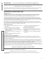 4
4
-
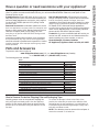 5
5
-
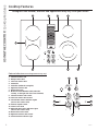 6
6
-
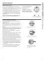 7
7
-
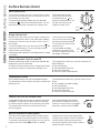 8
8
-
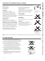 9
9
-
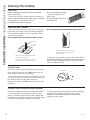 10
10
-
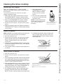 11
11
-
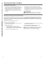 12
12
-
 13
13
-
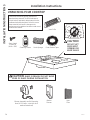 14
14
-
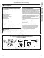 15
15
-
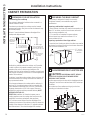 16
16
-
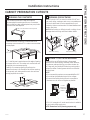 17
17
-
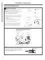 18
18
-
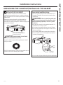 19
19
-
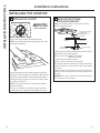 20
20
-
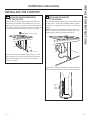 21
21
-
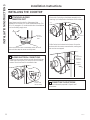 22
22
-
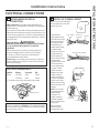 23
23
-
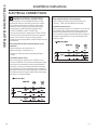 24
24
-
 25
25
-
 26
26
-
 27
27
-
 28
28
-
 29
29
-
 30
30
-
 31
31
-
 32
32
-
 33
33
-
 34
34
-
 35
35
-
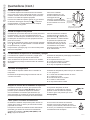 36
36
-
 37
37
-
 38
38
-
 39
39
-
 40
40
-
 41
41
-
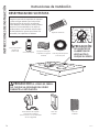 42
42
-
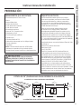 43
43
-
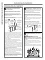 44
44
-
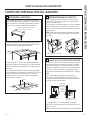 45
45
-
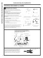 46
46
-
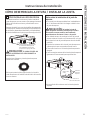 47
47
-
 48
48
-
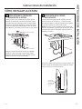 49
49
-
 50
50
-
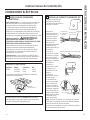 51
51
-
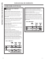 52
52
-
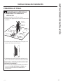 53
53
-
 54
54
-
 55
55
-
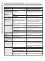 56
56


GE Profile PP9830DJBB Guía de instalación
- Tipo
- Guía de instalación
en otros idiomas
Artículos relacionados
Otros documentos
-
 GE Appliances JP5036SJSS El manual del propietario
-
GE PP9030DJBB El manual del propietario
-
 GE Profile Series PGP9830SJSS El manual del propietario
-
GEAppliances 49-85223-2 El manual del propietario
-
GE JBS55MMBS El manual del propietario
-
-
-
GE Appliances JP3536TJWW El manual del propietario
-
 GE Appliances JP3536TJWW El manual del propietario
-
GE JP5036SJSS Guía del usuario


