Glacier Bay 301879838 Guía de instalación
- Categoría
- Artículos sanitarios
- Tipo
- Guía de instalación

THANK YOU
INSTALLATION AND CARE GUIDE
SINGLE-HANDLE TUB AND SHOWER FAUCET
We appreciate the trust and condence you have placed in Glacier Bay through the purchase of this tub and
shower faucet. We strive to continually create quality products designed to enhance your home. Visit us online
to see our full line of products available for your home improvement needs. Thank you for choosing Glacier Bay!
Questions, problems, missing parts?
Before returning to the store, call Glacier Bay Customer Service
8 a.m. - 7 p.m., EST, Monday - Friday
9 a.m. - 6 p.m., EST, Saturday
1-855-HD-GLACIER (1-855-434-5224)
HOMEDEPOT.COM/GLACIERBAY
THD
11/2019 REV.02
Model#
873X-0804
873X-0827D
HD873X-0801
HD873X-0802
873X-0904
HD873X-0901
HD873X-0927D
SKU#
1001818631
1001819058
301879838
301879834
1001819034
301879836
301879832

2
Table of Contents
Important Information ..............................2
Warranty ...................................................2
Pre-Installation .........................................3
Planning Installation ..............................3
Package Contents ..................................6
Installation ................................................7
Care and Cleaning ....................................14
Troubleshooting ........................................15
Service Parts
...........................................
16
Important Information
□ Do not install this product until you read and understand the instructions in this manual. If you are installing this
product for someone else, leave this manual for the owner’s/ user’s reference.
□ Inlet ports are designed to allow for 1/2 in. COPPER tubing solder connection or 1/2 in. IPS threading coupling
connection. For threaded connections, wrap sealant tape around threaded ends before connecting. If soldering
connections, certain inammable parts should be removed prior to the soldering in order to avoid heat damage.
If you are unsure how to properly remove these parts, please call us at 1-855-HD-Glacier.
□ Protect your eyes with safety glasses when cutting or soldering water supply lines.
□ NOISE AND WATER HAMMER IN PEX SYSTEMS: Due to the inherent exibility of PEX compared with metallic
plumbing materials, water hammer and noise can sometimes occur from the pressure surges. It is important to
ensure the tubing is not in contact with wallboard, forced air ducts or other high-resonance materials. Clamping
or strapping can help prevent these noises. DO NOT USE PEX tubing from the valve to the tub spout.
Tools and Hardware Required ...............3
Warranty
LIMITED LIFETIME WARRANTY
Glacier Bay products are manufactured with superior quality standards and workmanship and are backed by our
limited lifetime warranty. Glacier Bay products are warranted to the original consumer purchaser to be free of
defects in materials or workmanship. We will replace FREE OF CHARGE any product or parts that proves defective.
Simply, return the product / part to any of The Home Depot retail locations or call 1-855-HD-GLACIER (1-855-434-
5224) to receive the replacement item. Proof of purchase (original sales receipt) from the original consumer
purchaser must be made available for all Glacier Bay warranty claims.
This warranty excludes incidental/inconsequential damages and failures due to misuse, abuse or normal wear and
tear. This warranty excludes all industrial, commercial and business usage, whose purchasers are hereby extended
a ve year limited warranty from the date of purchase, with all other terms of this warranty applying except the
duration of warranty.
Some states and provinces do not allow the exclusion or limitation of incidental or consequential damages, so the
above limitations may not apply to you. This warranty gives you specic legal rights and you may also have other
rights that vary from state to state and province to province. Please see a store or contact 1-855-HD-GLACIER for
more details.
Contact the Customer Service Team at 1-855-434-5224 or visit www.HomeDepot.com.

3 HOMEDEPOT.COM/GLACIERBAY
Please contact 1-855-HD-GLACIER for further assistance.
Safety
goggles
Thread
sealant tape
Tube
cutter
Strap wrench
Adjustable
wrench
Measuring
tape
Thermometer
Phillips
screwdriver
Flathead
screwdriver
SILICONE
Silicone
sealant
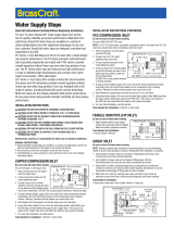
Pre-Installation
PLANNING INSTALLATION
Before beginning the installation of this product, ensure all parts are present. Compare parts with the Package
Contents list. If any part is missing or damaged, do not attempt to install the product. Contact Customer Service
for replacement parts.
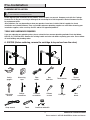
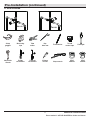
TOOLS AND HARDWARE REQUIRED
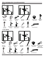
ADVANCED INSTALLATION: Consult a plumber or
professional before installing this product.
If you are replacing your plumbing valve, please review the four common plumbing methods illustrated below:
COPPER, IPS, PEX and CPVC. Remove the existing handle and valve trim before replacing your valve. Please follow
all local building and plumbing codes.
A. COPPER (Before soldering, remove the cartridge & stop valves from the valve)
Torch Lead-free solder Kit
Key
hole saw
Wire
brush
All installations can vary depending on how your previous faucet was installed. Not all supplies for faucet
installation are included; however, they are available wherever plumbing supplies are sold. When choosing your
installation supplies, make sure they are UPC and/or CSA approved products.
Flashlight

Pre-Installation (continued)
4
Safety
goggles
Thread
sealant tape
Tube
cutter
Strap wrench
Adjustable
wrench
Measuring
tape
Thermometer
Phillips
screwdriver
Flathead
screwdriver
SILICONE
Silicone
sealant
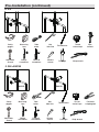
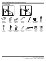
B. IPS
Key
hole saw
Flashlight
C. PEX+COPPER
Safety
goggles
Thread
sealant tape
Tube
cutter
Strap wrench
Adjustable
wrench
Measuring
tape
Thermometer
Phillips
screwdriver
Flathead
screwdriver
SILICONE
Silicone
sealant
Key
hole saw
Flashlight
Full circle
crimping tool
Pipe
wrench
COPPER
COPPER

HOMEDEPOT.COM/GLACIERBAY
Please contact 1-855-HD-GLACIER for further assistance.
Pre-Installation (continued)
5
D. CPVC+COPPER
Safety
goggles
Thread
sealant tape
Tube
cutter
Strap wrench
Adjustable
wrench
Measuring
tape
Thermometer
Phillips
screwdriver
Flathead
screwdriver
SILICONE
Silicone
sealant
Key
hole saw
Flashlight
CPVC
cleaner
P
i
p
e
J
o
i
n
t
C
o
m
p
o
u
n
d
CPVC
cement
P
i
p
e
J
o
i
n
t
C
o
m
p
o
u
n
d
COPPER
COPPER

6
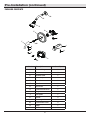
Pre-Installation (continued)
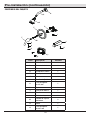
PACKAGE CONTENTS
Part Description Quantity
A
1
B Shower arm 1
C Shower head 1
D Valve body 1
E Escutcheon 1
F Handle 1
G Set screw 1
H 2.5mm hex wrench 1
Shower ange
I Plug 1
J Tub spout 1
K Screw 2
L Plaster guard 1
M Escutcheon screw 2
N Index 1
O 3.97mm hex wrench 1
A
B
M
C
D
E
F
G
H
I
J
L
K
N
O

7
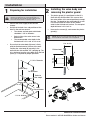
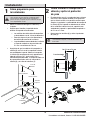
Installation
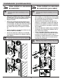
1
Preparing for installation
CAUTION: Always shut off the water supply before
removing an existing faucet or replacing any part of a
faucet. Open the faucet handle to relieve water pressure
and ensure that the water is completely shut off.
HOMEDEPOT.COM/GLACIERBAY
Please contact 1-855-HD-GLACIER for further assistance.
30 in.
Tub & Shower
8 in. Min.
48 in.
Shower Only
1 1/4 in. Diamter
1 1/4 in. Diameter
48 in.
Tub & Shower
Refer to
the step 2
30 in.
Shower Only
D
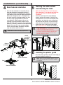
2
Installing the valve body and
removing the plaster guard
□ Shut off the water supply to the tub and
shower.
□ Verify that the hole sizes and positions of the
holes in the wall are correct:
□ The shower and tub spout outlet holes
should be 1-1/4 in. diameter.
□ Refer to Step 2 for valve access hole
dimensions.
□ The recommended valve depth to the
nished wall is 2 in. min. to 3 in. max.
□ Ensure that the valve body (D) cover is ush
with the nished exterior surface of the wall.
Position the valve body (D) correctly in the
wall with the side marked "UP" pointing up. The
8 in. minimum from the valve body (D) to the tub
spout (J) is required for proper operation.
The plaster guard (L) is positioned so that it is
ush with the nished wall. This ensures that
the valve will be at the correct position to accept
the trim. The depth for the valve body (D) in wall
is measured from the center of the shower
outlet to the nished wall surface. The accepted
depth distance is 2 in. to 3 in..
□
Unscrew the screws (K), and remove the plaster
guard (L).
□
NOTE: Be sure to position the valve body (D) correctly in
the wall, with the side marked "UP" facing upward.
2 in. to 3 in.
Finished wall
6 in. dia.
D
L
L
K

8
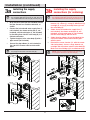
Installation (continued)
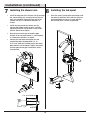
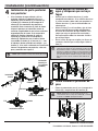
3a
Installing the supply
connections
□
□ Tighten the pipes to the valve body (D) with a
pipe wrench (not included).
Wrap thread sealant tape (not included) around
the pipe threads in a clockwise direction, as
shown.
□
Connect the hot and cold water supply lines (1,
not included), the shower outlet pipe (2, not
included), and tub outlet pipe (3, not included)
by threading them into the valve body (D) in a
clockwise direction.
Connect the pipe elbows (4, not included) to
the end of the shower outlet and tub outlet
pipes.
□
NOTE: The hot water supply lines go into the "H" inlet, and
the cold water supply lines go into the "C" inlet. Do not use
PEX or CPVC between the valve body (D) and tub spout (J).
NOTE: If you do not wish to install the tub outlet, insert
the plug (I) into the bottom of the valve body (D).
3
D
1
2
4
D
1
2
4
I
3b
Installing the supply
connections (for soldering)
□
Before soldering, remove the screw (11),
inverter (12), sleeve (1), o-ring (2), bonnet nut (3),
cartridge (4), o-ring (5) and stop valves (6) from
the valve body (D).
□
Solder the hot and cold water supply lines (7,
not included), the shower outlet pipe (8, not
included), and tub outlet pipe (9, not included)
into the valve body (D) with the torch.
Solder the pipe elbows (10, not included) to the
end of the shower outlet and tub outlet pipes
with the torch.
□
Reinstall the screw, inverter (12, with the arrow
side facing down), sleeve, o-rings, bonnet nut,
cartridge and stop valves onto the valve body (D).
Make sure the cartridge (4) is installed correctly.
□
NOTE: The hot water supply lines go into the "H" inlet, and
the cold water supply lines go into the "C" inlet. Do not use
PEX or CPVC between the valve body (D) and tub spout (J).
NOTE: If you do not wish to install the tub outlet, insert
the plug (I) into the bottom of the valve body (D).
3
D
8
10
9
1
2
4
5
7
7
6
11
12
I
3
D
8
10
1
2
4
5
7
7
6
11
12
4

9
HOMEDEPOT.COM/GLACIERBAY
Please contact 1-855-HD-GLACIER for further assistance.
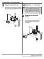
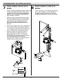
4
Back to back installation
NOTE: Never install the valve body (D) upside down!
□ If the hot and cold inlets are reversed (hot on
right and cold on left), remove the screw (1),
inverter (2), sleeve (3), and bonnet (4) from the
valve body (D) with reversed supply connections.
Rotate the cartridge (5) 180°, so H appears on
the right. Install the cartridge making sure that
the key is fully engaged with the slot in the
valve body (D). Slide the bonnet (4) over the
cartridge (5) and thread them onto the valve
body (D). Hand tighten securely. Reassemble the
sleeve (3), inverter (2, with the arrow side facing
down) and screw (1). If you are not making a
reverse or back to back installation, skip this
step and continue with the step 5.
Installation (continued)
6
Installing the plaster guard
Place the plaster guard (L) onto the valve body (D)
and secure with the screws (K).
□
5
Flushing the water outlets
□
and checking for leaks
Place the handle (F) on the valve body (D)
inverter and turn the handle (F) to the full on
mixed position. Turn on the hot and cold water
supply lines and allow the water to ow from
the outlets for one minute, or until all foreign
matter has been ushed out. Check for leaks.
Shut off the water at the faucet and supply
lines. Check for leaks. Remove the handle (F).
□
Make sure the stop valves (1) are fully open.
If the stop valves (1) are closed, you must fully
open the stop valves (1) with the athead
screwdriver.
□
NOTE: Be sure to position the plaster guard (L) correctly
onto the valve body (D), with the side marked "SHOWER"
facing upward.
Normal
installation
(changes
not required)
Reverse
installation
D
Cold
Hot
L
D
K
NOTE: Check for leaks
a. Turn off the integral stops, check if there are any leaks
on both of the inlet water supply connections.
b. Fully turn on the integral stops and use plug/cap to block
the outlets of shower head and spout, then turn on the
water and check if there are any leaks on the outlet
pipe/tube connections or elbows.
1
2
3
4
5
Normal installation
Reverse installation
H
Hot
Hot
Cold
Cold
H
F
D
1
1

10
Installation (continued)
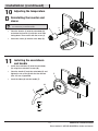
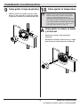
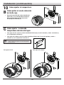
7
Installing the shower arm
□ Insert the long end of the shower arm (B) through
the shower ange (A), and wrap thread sealant
tape (not included) around the long end of the
shower arm (B) in a clockwise direction, as
shown.
Install the long end of the shower arm (B)
into the pipe elbow inside the wall. Carefully
tighten the shower arm (B) with a clean strap
wrench. Do not over tighten.
□
Wrap thread sealant tape around the pipe
threads of the tub spout outlet (1, not included)
in a clockwise direction, as shown.
□
Connect the tub spout outlet pipe (the tub
spout outlet pipe should project 1 in. to
2-15/16 in. from the nished wall) to the lower
pipe elbow (2, not included). Tighten the elbow
and tub spout outlet pipe connections with a
strap wrench.
□
8
Installing the tub spout
Place the spout (J) onto quick connection until
the spout (J) becomes ush with the nished
wall and tighten the screw (1) with with the
Hex wrench (Hex: 3.97mm, O) provided.
□
1
1 in. to 2-15/16 in.
Wall
1
2
B
A
J
O
1

11
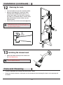
Installation (continued)
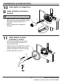
□ Unscrew the sleeve (1) from the valve body (D).
□ Unscrew the screw (2) from the inverter (3),
and then remove the inverter (3) from the
valve body (D).
HOMEDEPOT.COM/GLACIERBAY
Please contact 1-855-HD-GLACIER for further assistance.
10
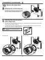
Adjusting the temperature
9
Removing the plastic cap
□ Before installing the escutcheon (E), remove the
plastic cap (1) from the valve body (D) by twisting
the cap in a clockwise direction.
NOTE: The limiter on the valve can be set to allow partial
or full access to hot water by limiting how far the handle
can be turned to the hot side of the valve. The limiter is
typically set at the factory to allow only warm water to pass
through the valve. Follow the directions in this section if you
wish to adjust the amount of hot water that is allowed
through the valve. If you do not wish to adjust the amount
of hot water that is allowed through the valve, proceed to
the step 11, and skip over the step 10 (A, B, C, D).
A
Removing the sleeve and
inverter
1
D
D
3
1
2

12
Installation (continued)
10
Adjusting the temperature
C
Adjusting the desired maximum
water temperature
□ For colder water, adjust the red limit stop ring (1) in a clockwise direction and reinstall the red limit stop
ring (1) onto the cartridge assembly (2).
□ For hotter water, adjust the red limit stop ring (1) in a counterclockwise direction and reinstall the red
limit stop ring (1) onto the cartridge assembly (2).
B
Removing the red limit stop ring
□ Remember the position of the red limit stop ring (1)
on the cartridge assembly (2). Remove the red limit
stop ring (1) from the cartridge assembly (2).
NOTE: A thermometer (not included) can be held in the
running water to aid in reaching the desired water
temperature.
For hotter waterFor colder water
1
2
1
2
1
2
J

Installation (continued)
HOMEDEPOT.COM/GLACIERBAY
Please contact 1-855-HD-GLACIER for further assistance.
10
Adjusting the temperature
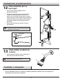
13
D
Reinstalling the inverter and
sleeve
□ Place the inverter (2) onto the valve body (D)
and rotate the inverter (2) with the arrow side
facing down. Then secure with the screw (3).
□ Screw the sleeve (4) onto the valve body (D).
NOTE: Rotate the cartridge stem (1) clockwise to turn off
the water before you install the handle.
11
Installing the escutcheon
and handle
□ Install the escutcheon (E) onto the valve body
(D) using the escutcheon screws (M).
Place the handle (F) onto the valve body (D) and
tighten the set screw (G) with the Hex wrench
(Hex: 2.5 mm, H) provided.
□
Insert the index (N) into the handle (F).
□
2
4
3
D
1
E
M
F
G
D
H
N

Installation (continued)
13
Installing the shower head
□ Attach the shower head (C) to the shower arm
(B). Hand-tighten only.
12
Checking for leaks
□
□
Turn the handle (F) to the full on mixed position.
When the valve body (D) is turned on, water
normally ows through the tub spout (J). To
activate the shower, turn the valve on and pull
the knob (1) up. Hold the knob (1) until the water
ows continuously from the shower arm (B).
Check for leaks.
Shut off the water at the faucet and supply lines. □
14
Care and Cleaning
□ To clean, wipe down with a damp cloth and dry with a towel.
□ Do not use abrasive cleaners, steel wool, or harsh chemicals when cleaning this faucet, or the warranty will
be voided.
UP
FOR
SHOWER
1
J
D
F
J
B
B
C
NOTE: When the pattern of the water ow switches to
the shower from the tub spout, some low leakage from the
tub spout is a normal occurrence.
NOTE: Do not use the thread sealant tape and do not use
wrench to tighten shower head.

15
HOMEDEPOT.COM/GLACIERBAY
Please contact 1-855-HD-GLACIER for further assistance.
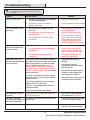
Troubleshooting
NOTE: Refer to the Service Parts section in this manual
for a detailed drawing showing the location of the parts
listed below.
Problem Possible Cause Solution
There is no hot water. □ Rotate the cartridge 180°.
□ Clean the bottom of the cartridge.
There is no ow or a low
water ow.
□ Turn both water supply valves
to the on position.
□ Fully turn on the stop valves.
□ Turn off the water supply at
angle valve and unscrew the
spray head from spray hose.
Clean the screen lter in the
spray head under running water.
There is leaking or dripping
from the spout when the
handle is closed.
□ Reinstall the cartridge.
□ Check to ensure the sealed
washer on the cartridge is in
place or replace the cartridge.
□ Use wrench to retighten the
bonnet nut sufciently.
Water comes out of the
tub spout and showerhead
at the same time.
If the pattern of the water ow switches to
the shower from the tub spout, and the leak
from the tub spout is less than 0.01 GPM,
this is a normal occurrence. If there is
residual water on the shower head when
the water from the shower head is turned
off, this is a normal occurrence. Or consider
the causes below:
! The pipe used between the valve and the
tub spout is not 1/2 in. IPS, or the COPPER
pipe is incorrect.
! The valve is installed upside down.
! There is a restriction between the valve
and the tub spout.
! The distance between the valve and the
showerhead is less than 48 in..
□ Change the pipe to IPS or
COPPER.
□ The distance from the
showerhead and valve moved
to at least 48 in..
□ Remove the tub spout and ush
out debris and/or replace the
undersized line or ttings.
□ Remove the valve and reinstall it
using the correct orientation.
The temperature range is
restricted.
The position of the temperature limit stop
is out of ideal range.
□
Refer to the section Adjusting
the Temperature in step 10.
The handle cannot be
installed or the handle rubs
against the escutcheon.
The valve is installed too far back from the
nished wall.
□ Reinstall the valve (refer to Step
2 of the Installation section).
The handle is hard to turn. The bonnet nut is too tight. □ Loosen the bonnet nut and
reinstall it. Do not overtighten.
□ The lines are reversed or the cartridge
is installed upside down.
□ One or both water supplies are not
turned on.
□ The stop valves are turned off or not
fully turned on.
□ The screen lter in the spray head
is blocked.
□ The cartridge is not properly installed.
□ The sealed washer on the cartridge is
not in place.
□ The bonnet nut is not tightened
sufciently.
□ The balance valve in cartridge is
clogged with debris.

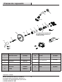
16
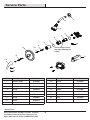
Part Description Part Number
1 RP38046*
2 Shower arm RP38047*
3 Shower head RP38306*
4 O-ring RP60101
5 Cartridge RP20075
6 Bonnet nut RP7043701
7 O-ring RP60091
8 Sleeve RP80553*
9 Inverter RP70559
Shower ange
Part Description Part Number
10 Screw RP70560
11 Escutcheon RP80554*
12 Escutcheon screw RP50190*
13 Handle RP13469*
14 Set screw RP50002
15 Index RP10055
16 Plug RP70365
17 Spout RP33073*
Service Parts
*Specify Finish
Many replacement cartridges, aerators, and drain
assemblies can be purchased at your local The
Home Depot store or online at HOMEDEPOT.COM
Faucet ID tags can be
found by removing the
handle
14
13
12
16
3
2
1
7
6
5
4
10
9
8
11
15
17

Questions, problems, missing parts?
Before returning to the store, call Glacier Bay Customer Service
8 a.m. - 7 p.m., EST, Monday - Friday
9 a.m. - 6 p.m., EST, Saturday
1-855-HD-GLACIER (1-855-434-5224)
HOMEDEPOT.COM/GLACIERBAY
Retain this manual for future use.

GUÍA DE USO Y MANTENIMIENTO
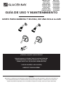
GRIFO PARA BAÑERA Y DUCHA, DE UNA SOLA LLAVE
Apreciamos la conanza que has depositado en Glacier Bay al comprar este grifo para bañera y ducha. Nos esforzamos por
crear continuamente productos de calidad diseñados para mejorar tu hogar. Visítanos en Internet para ver nuestra línea
completa de productos disponibles para las necesidades de mejoras de tu hogar. ¡Gracias por elegir a Glacier Bay!
GRACIAS
¿Problemas, preguntas o piezas faltantes?
Antes de regresar a la tienda, llama al servicio al cliente de
Glacier Bay de lunes a viernes entre 8 a.m. y 7 p.m. y los
sábados entre 9 a.m. y 6 p.m.(hora estándar del Este)
1-855-HD-GLACIER (1-855-434-5224)
HOMEDEPOT.COM/GLACIERBAY
Modelo núm.
873X-0804
873X-0827D
HD873X-0801
HD873X-0802
873X-0904
HD873X-0901
HD873X-0927D
SKU núm.
1001818631
1001819058
301879838
301879834
1001819034
301879836
301879832

19
Tabla de contenido
Información importante .........................19
Garantía...................................................19
Pre-instalación .......................................20
.............20
Herramientas y herrajes necesarios ....20
Contenido del paquete .........................23
Instalación ..............................................24
Planicación de la instalación
Cuidado y limpieza ................................31
Piezas de repuesto ................................33
Solución de problemas ...........................32
Información importante
□ No instales este producto hasta que hayas leído y entendido las instrucciones de este manual. Si estás instalando
este producto para alguien, déjale este manual para que le sirva como referencia al dueño/usuario.
□ Los puertos de entrada están diseñados para 1/2 plg. Conexión de soldadura de tubería de COBRE o 1/2 plg.
Conexión de acoplamiento de rosca IPS. Para conexiones roscadas, envuelve los extremos roscados con cinta
selladora antes de conectar. Si vas a soldar las conexiones, algunas partes inamables deben quitarse antes
de la soldadura para evitar daños por calor. Si no estás seguro sobre cómo quitar estas partes, llámanos a
1-855-HD-Glacier.
□ Al soldar o cortar las líneas de suministro de agua, protege tus ojos con gafas de seguridad.
□ RUIDO Y GOLPE DE ARIETE EN SISTEMAS PEX: Debido a la exibilidad inherente del PEX, en comparación con
materiales de plomería metálicos, el ruido y golpe de ariete puede ocurrir de vez en cuando por sobrecargas
de presión. Es importante garantizar que la tubería no esté en contacto con paneles de pared, ductos de aire
propulsado u otros materiales de alta resonancia. La sujeción o anclaje son métodos para evitar estos ruidos.
NO USES tuberías PEX desde la válvula al caño de la bañera.
Garantía
GARANTÍA DE POR VIDA LIMITADA
Los productos de Glacier Bay están fabricados con normas y mano de obra de calidad superior y están respaldados
por nuestra garantía de por vida limitada. Los productos de Glacier Bay están garantizados al comprador consumidor
original de estar libres de defectos en materiales o mano de obra. Reemplazaremos LIBRE DE CARGOS cualquier
producto o pieza que se demuestre está defectuosa. Símplemente, devuelva el producto a cualquiera de las
ubicaciones de venta al detalle de The Home Depot o llame al 1-855-HD-GLACIER (1-855-434-5224) para recibir el
artículo de reemplazo. La prueba de compra (recibo de venta original) del comprador consumidor original debe estar
disponible para todos los reclamos de garantía de Glacier Bay.
Esta garantía excluye daños y fallos incidentales/consecuenciales debido al mal uso, abuso o desgaste normal por
el uso. Esta garantía excluye todos los usos industriales, comerciales y de negocios, a cuyos compradores por la
presente, se les ha ampliado una garantía limitada de cinco años a partir de la fecha de compra, con todos los otros
artículos de esta garantía que aplican excepto la duración de la garantía.
Algunos estados y provincias no permiten la exclusión o la limitación de los daños incidentales o consecuenciales,
por lo tanto, las limitaciones y exclusiones anteriores podrían no aplicar a usted. Esta garantía le otorga derechos
legales especícos y también puede tener otros derechos que varían de un estado a otro. Por favor, vaya a una
tienda o llame al 1-855-HD-GLACIER para más detalles.
Póngase en contacto con el Equipo de Servicio al Cliente llamando al 1-855-434-5224 o visite www.HomeDepot.com.

20 HOMEDEPOT.COM/GLACIERBAY
Para obtener asistencia, llama al 1-855-HD-GLACIER.
Pre-instalación
PLANIFICACIÓN DE LA INSTALACIÓN
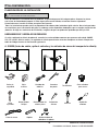
Gafas de
seguridad
Cinta selladora
para roscas
Cortador de
tuberías
Llave de correa
Llave
ajustable
Cinta
métrica
Termómetro
Destornillador
Phillips
Destornillador de
cabeza plana
SILICONE
Sellador de
silicona
Antes de comenzar la instalación de este producto, asegúrate de que no falta ninguna pieza. Compara las piezas
con la lista de Contenido del paquete. Si falta alguna pieza o está dañada, no intentes instalar el producto.
Comunícate con el servicio al cliente para piezas de repuesto.
HERRAMIENTAS Y HERRAJES NECESARIOS
INSTALACIÓN AVANZADA: Consulta a un plomero o
profesional antes de instalar este producto.
Si estás cambiando tu válvula de plomería, consulta los cuatro métodos comunes que aparecen más abajo: COBRE,
IPS, PEX y CPVC. Quita la manija y el regulador de válvula preexistentes antes de reemplazar tu válvula. Cumple con
todos los códigos locales de construcción y plomería.
A. COBRE (Antes de soldar, quita el cartucho y las válvulas de cierre del cuerpo de la válvula)
Soplete Kit de alambre de
soldadura sin plomo
Serrucho
de punta
Cepillo de
alambre
Todas las instalaciones pueden variar en dependencia de cómo estaba instalado el grifo anterior. No se incluyen todos
los suministros para la instalación del grifo; sin embargo, están disponibles dondequiera que se vendan suministros de
plomería. Al elegir tus suministros de instalación, asegúrate de que son productos aprobados por UPC y/o CSA.
Linterna

Pre-instalación (continuación)
21
B. IPS
Gafas de
seguridad
Cinta selladora
para roscas
Cortador de
tuberías
Llave de correa
Llave
ajustable
Cinta
métrica
Termómetro
Destornillador
Phillips
Destornillador de
cabeza plana
SILICONE
Sellador de
silicona
Serrucho
de punta
Linterna
C. PEX+COBRE
Gafas de
seguridad
Cinta selladora
para roscas
Cortador de
tuberías
Llave de correa
Llave
ajustable
Cinta
métrica
Termómetro
Destornillador
Phillips
Destornillador de
cabeza plana
SILICONE
Sellador de
silicona
Serrucho
de punta
Linterna
Herramienta para
engarzar de
círculo completo
COBRE COBRE
Llave para
tubería

HOMEDEPOT.COM/GLACIERBAY
Para obtener asistencia, llama al 1-855-HD-GLACIER.
Pre-instalación (continuación)
22
D. CPVC+COBRE
Gafas de
seguridad
Cinta selladora
para roscas
Cortador de
tuberías
Llave de correa
Llave
ajustable
Cinta
métrica
Termómetro
Destornillador
Phillips
Destornillador de
cabeza plana
SILICONE
Sellador de
silicona
Serrucho
de punta
Linterna
Limpiador
CPVC
P
i
p
e
J
o
i
n
t
C
o
m
p
o
u
n
d
Cemento
CPVC
P
i
p
e
J
o
i
n
t
C
o
m
p
o
u
n
d
COBRE
COBRE

23
Pieza Descripción Cantidad
A
1
B Brazo de la ducha 1
C Cabezal de la ducha 1
D Cuerpo de la válvula 1
E Placa protectora 1
F Llave 1
G Tornillo de jación 1
H
Llave hexagonal
de 2.5 mm
1
Brida de la ducha
I Tapón 1
J Caño de la bañera 1
Pre-instalación (continuación)
CONTENIDO DEL PAQUETE
K Tornillo 2
L Protector de yeso 1
M
Tornillo de la placa
protectora
2
A
B
M
C
D
E
F
G
H
I
J
L
K
N
O
N Índice 1
O
Llave hexagonal
de 3.97 mm
1

24
Instalación
1
Cómo prepararse para
la instalación
76.2 cm
Bañera y ducha
20.3 cm mín.
1.22 m
Ducha solamente
3.2 cm
de diámetro
3.2 cm de
diámetro
1.22 m
Bañera y ducha
76.2 cm
Ducha solamente
PRECAUCIÓN: Cierra siempre el suministro de agua
antes de retirar un grifo existente o reemplazar alguna
parte del mismo. Abre la llave del grifo para liberar la
presión de agua y asegúrate de que el suministro de agua
esté completamente cerrado.
HOMEDEPOT.COM/GLACIERBAY
Para obtener asistencia, llama al 1-855-HD-GLACIER.
Consulta
el paso 2
D
2
Cómo instalar el cuerpo de la
válvula y quitar el protector
de yeso
De 5.1 cm a 7.6 cm
Pared acabada
diámetro de 15.2 cm
□ Cierra el suministro de agua a la bañera y a
la ducha.
□ Verica que el tamaño y la posición de los
oricios en la pared sean correctos:
□ Los oricios de salida del caño de bañera
y ducha deben ser de 3.2 cm de diámetro.
□ Consulta el paso 2 para las dimensiones
del oricio de acceso de la válvula.
□ La profundidad recomendada de la válvula
a la pared acabada es de un mínimo de
5.1 cm a un máximo de 7.6 cm.
□ Asegúrate de que la cubierta del cuerpo de la
válvula (D) esté al ras de la supercie exterior
con acabado de la pared. Coloca el cuerpo de
la válvula (D) correctamente en la pared con el
lado de la marca "UP" hacia arriba. Para
funcionamiento adecuado, se requieren 20.3 cm
de separación mínima entre el cuerpo de la
válvula (D) y el caño de la bañera (J).
El protector de yeso (L) se coloca de forma tal que
esté al ras con la pared acabada. Esto garantiza
que la válvula estará en la posición correcta para
aceptar el regulador. La profundidad del cuerpo de
la válvula (D) en la pared se mide desde el centro
de la salida de la ducha hasta la supercie con
acabado de la pared. La profundidad aceptada es
de 5.1 cm a 7.6 cm.
□
Desenrosca los tornillos (K) y retira el protector
de yeso (L).
□
NOTA: Asegúrate de colocar el cuerpo de la válvula (D)
correctamente en la pared, con el lado de la marca "UP"
hacia arriba.
D
L
L
K

25
Instalación (continuación)
3a
Cómo instalar las conexiones
de suministro
□
□ Aprieta las tuberías al cuerpo de la válvula con una
llave para tubería (no incluido).
Coloca cinta selladora para roscas (no incluido)
alrededor de las roscas de la tubería en dirección
de las manillas del reloj, tal como muestra el
diagrama anterior.
□
Conecta los suministros de agua caliente y fría
(1, no incluido), la tubería de salida de la ducha
(2, no incluido) y la tubería de salida de la bañera
(3, no incluido) enroscándolas en dirección de
las manillas del reloj en el cuerpo de la válvula
(D).
Conecta los codos de la tubería (4, no incluido)
al extremo de las tuberías de salida de la bañera
y de la ducha.
□
NOTA: Las líneas de suministro de agua caliente van en la
entrada “H” y las de agua fría, en la entrada “C”. No uses
PEX ni CPVC entre el cuerpo de la válvula (D) y el caño de la
bañera (J).
NOTA: Las líneas de suministro de agua caliente van en la
entrada “H” y las de agua fría, en la entrada “C”. No uses
PEX ni CPVC entre el cuerpo de la válvula (D) y el caño de la
bañera (J).
NOTA: Si no deseas instalar la salida de la bañera, inserta
el tapón (I) en la parte inferior del cuerpo de la válvula (D).
NOTA: Si no deseas instalar la salida de la bañera, inserta
el tapón (I) en la parte inferior del cuerpo de la válvula (D).
3
D
1
2
4
D
1
2
4
I
3b
Cómo instalar las conexiones
de suministro (para soldar)
□
Antes de soldar, quita el tornillo (11), el inversor
(12), la funda (1), el aro tórico (2), la tuerca ciega
(3), el cartucho (4), el aro tórico (5) y las válvulas
de cierre (6) del cuerpo de la válvula.
□
Suelda las líneas de suministro de agua fría y
caliente (7, no incluidas), la tubería de salida de
la ducha (8, no incluida y la tubería de salida de
la tina (9, no incluida) al cuerpo de la válvula (D)
con el soplete.
Suelda los codos de la tubería (10) (no incluidos)
al extremo de las tuberías de salida de la tina y
de la ducha con el soplete.
□
Vuelve a ensamblar el tornillo, el inversor (12)
— con el lado de la echa mirando hacia abajo),
la funda, los aros tóricos, la tuerca ciega, el
cartucho y las válvulas de cierre en el cuerpo de
la válvula (D). Asegura que el cartucho (4) esté
instalado correctamente.
□
3
D
8
10
9
1
2
4
5
7
7
6
11
12
I
3
D
8
10
1
2
4
5
7
7
6
11
12
4

26
Instalación (continuación)
6
Cómo instalar el protector de
yeso
Coloca el protector de yeso (L) en el cuerpo de la
válvula (D) y asegúralo con los tornillos (K).
□
HOMEDEPOT.COM/GLACIERBAY
Para obtener asistencia, llama al 1-855-HD-GLACIER.
5
Cómo purgar las salidas de
agua y chequear que no haya
fugas
□ Coloca la llave (F) en el invertidor y gira la llave
hasta la posición de mezclado completo.Abre
las líneas de suministro de agua caliente y fría
y deja que salga el agua durante un minuto o
hasta que expulse todos los desechos. Verica
que no haya fugas.
Cierra la llave de agua en el grifo y las líneas de
suministro. Verica que no haya fugas. Quita la
llave (F).
□
4
Instalación de parte posterior
con posterior
NOTA: ¡Nunca instales el cuerpo de la válvula (D) al revés!
NOTA: Asegúrate de colocar el protector de yeso (L)
correctamente sobre el cuerpo de la válvula (D), con el lado
de la marca “SHOWER” (ducha) hacia arriba.
□ Si las entradas de agua caliente y fría se
revierten (caliente a la derecha y fría a la
izquierda), quita el tornillo (1), el inversor (2),
la funda (3) y el bonete (4) del cuerpo de la
válvula (D) con conexiones de suministro
revertidas. Rota el cartucho (5) 180° de forma
tal que H aparezca en la derecha. Instala el
cartucho asegurándote de que la llave esté bien
enganchada con la ranura en el cuerpo de la
válvula (D). Desliza el bonete (4) sobre el
cartucho (5) y enrosca en el cuerpo de la
válvula (D). Aprieta bien con la mano. Vuelve
a ensamblar la funda (3), el inversor (2) — con
el lado de la echa mirando hacia abajo— y el
tornillo (1). Si no estás realizando una instalación
inversa o de posterior con posterior, salta este
paso y continúa con el paso 5.
D
1
2
3
4
5
H
H
Instalación
normal (no
se requieren
cambios)
Instalación
inversa
Instalación normal
Instalación inversa
Caliente
Caliente
Fría
Fría
Fría
Caliente
Verica que las válvulas de cierre (1) estén
completamente abiertas. Si las válvulas de cierre
(1) están cerradas, debes abrir por completo las
válvulas de cierre (1) con el destornillador con
cabeza plana.
□
L
D
K
NOTA: Verica que no haya fugas
a. Desactiva las válvulas de cierre integradas, verica que no
haya pérdidas en ambas conexiones de suministro de agua.
b. Activa por completo las válvulas de cierre integradas y usa
tapón/tapa para bloquear las salidas del cabezal de la ducha
y el caño, luego abre el suministro de agua y verica si hay
fugas en los codos o en las conexiones de las tuberías de
salida.
F
D
1
1

27
Instalación (continuación)
7
Cómo instalar el brazo de la
ducha
□
Pared
De 2.5 cm a 7.5 cm
Inserta el extremo largo del brazo de la ducha (B)
a través de la brida de esta (A) y coloca cinta
selladora para rosca (no incluida) alrededor de
aquel (B), en el sentido de las manecillas del
reloj, tal como se muestra.
Coloca el extremo largo del brazo de la ducha
dentro del codo de tubería que está dentro de
la pared. Aprieta con cuidado el brazo de la
ducha con una llave de correa limpia. No
aprietes demasiado ya que podrías dañar el
brazo (B).
□
Coloca cinta selladora para roscas alrededor de
las roscas de la tubería del caño de la bañera
(1, no incluido) en dirección de las manillas del
reloj, tal como muestra el diagrama anterior.
□
Conecta la tubería de salida del caño de la
bañera (la tubería de salida del caño de la
bañera debe salir de 2.5 cm a 7.5 cm de la
pared terminada) al codo de la tubería inferior
(2, no incluido). Aprieta los codos y las
conexiones de la tubería de salida del caño de
la bañera con una llave de correa.
□
8
Cómo instalar el caño de la
bañera
Enrosca el caño (J) en la conexión rápida hasta
que el caño (J) quede a ras de la pared con
acabado y aprieta el tornillo (1) con la llave
hexagonal (hexagonal de 3.97 mm, O) incluida.
□
1
1
2
B
A
J
O
1

28
Instalación (continuación)
9
Cómo quitar la tapa de plástico
10
Cómo ajustar la temperatura
A
Cómo quitar la manija, la funda
y el inversor
□ Desatornilla el tornillo (2) del inversor (3) y luego
quita el inversor (3) del cuerpo de la válvula (D).
□ Desenrosca la funda (1) del cuerpo de la
válvula (D).
HOMEDEPOT.COM/GLACIERBAY
Para obtener asistencia, llama al 1-855-HD-GLACIER.
□ Antes de instalar el escudete (E), quita la tapa
plástica (1) del cuerpo de la válvula (D) girando
la tapa en el sentido de las manecillas del reloj.
NOTA: El limitador de la válvula puede congurarse para
permitir acceso parcial o total al agua caliente al limitar
hasta dónde puede girarse la manija en el lado del agua
caliente de la válvula. El limitador usualmente está
congurado de fábrica para permitir sólo el paso de agua
tibia a través de la válvula. Sigue las instrucciones de esta
sección si deseas ajustar la cantidad de agua caliente que
pasa a través de la válvula. Si no deseas ajustar la cantidad
de agua caliente que pasa a través de la válvula, ignora el
paso 10 (A, B, C, D) y continúa con el paso 11.
1
D
D
3
1
2

29
Instalación (continuación)
10
Cómo ajustar la temperatura
B
Cómo quitar el aro de retención
de límite rojo
□ Recuerda la posición del aro de retención del
límite rojo (1) en el conjunto del cartucho (2).
Quita el aro del tope de límite rojo (1) del
ensamblaje del cartucho (2).
C
Cómo ajustar la deseada
temperatura máxima del agua
□ Para agua más fría, ajusta el aro de retención del límite rojo (1) hacia la derecha y vuelve a instalarlo (1)
en el conjunto del cartucho (2).
□ Para agua más caliente, ajusta el aro de retención del límite rojo (1) hacia la izquierda y vuelve a
instalarlo (1) en el conjunto del cartucho (2).
NOTA: Puede colocarse un termómetro (no incluido) en
el agua corriente para ayudar a alcanzar la temperatura
deseada del agua.
Para agua más fría Para agua más caliente
1
2
1
2
1
2
J

Instalación (continuación)
HOMEDEPOT.COM/GLACIERBAY
Para obtener asistencia, llama al 1-855-HD-GLACIER.
10
Cómo ajustar la temperatura
30
D
Cómo reinstalar el inversor y
la funda
□ Coloca el inversor (2) en el cuerpo de la válvula
(D) y gíralo (2) con el lado de la echa mirando
hacia abajo. Enseguida asegura con el
tornillo (3).
□ Enrosca la funda (4) en el cuerpo de la
válvula (D).
NOTA: Rota el vástago del cartucho (1) hacia la derecha
para cortar el suministro de agua antes de instalar la manija.
11
Cómo instalar la placa
protectora y la llave
□ Instala la placa protectora (E) en el cuerpo
de la válvula (D) usando los tornillos para
la placa protectora (M).
Coloca la llave (F) en el cuerpo de la válvula (D)
y aprieta el tornillo de jación (G) con la llave
hexagonal (hexagonal de 2.5 mm, H) incluida.
□
Inserta el índice (N) en la llave (F).
□
2
4
3
D
1
E
M
F
G
D
H
N

Instalación (continuación)
13
Cómo instalar el cabezal de
la ducha
□ Fija el cabezal de la ducha (C) en el brazo de la
ducha (B). Ajusta sólo con la mano.
12
Cómo comprobar que no
haya fugas
□
□
Gira la manija (F) por completo hacia la
posición de mezclado.
Cuando el cuerpo de la válvula (D) está abierto,
el agua sale normalmente por el caño de la
bañera (J). Para activar la ducha, abre la válvula
y hala la perilla (1) hacia arriba. Sostén la perilla (1)
hasta que el agua corra de forma continua desde
el brazo de la ducha (B). Verica que no haya
ltraciones.
Cierra la llave de agua en el grifo y las líneas
de suministro.
□
HACIA ARRIBA
PARA LA
DUCHA
31
Cuidado y limpieza
□ Para limpiar, usa un paño húmedo y seca con una toalla.
□ No uses limpiadores abrasivos, esponjas de alambre o productos químicos fuertes para limpiar esta
mezcladora, pues ello anulará la garantía.
1
J
D
F
J
B
B
C
NOTA: Cuando el patrón de ujo de agua cambia del caño
de la bañera a la ducha, es normal que haya una pequeña
ltración del caño de la bañera.
NOTA: No uses la cinta selladora para rosca y no uses la
llave para apretar el cabezal de la ducha.

32
HOMEDEPOT.COM/GLACIERBAY
Para obtener asistencia, llama al 1-855-HD-GLACIER.
Solución de problemas
NOTA: Consulta en la sección de piezas de repuesto de
este manual una ilustración detallada sobre la ubicación
de las piezas enumeradas más abajo.
Problema Posible causa Solución
No hay agua caliente. □ Rota 180° el cartucho.
□ Limpia la parte inferior del
cartucho.
No hay ujo de agua o es
insuciente.
□ Gira las válvulas de suministro
de agua hasta la posición de
“abierto”.
□ Abre las válvulas de cierre por
completo.
□ Cierra el suministro de agua en
la válvula angular y desenrosca
el cabezal del rociador de la
manguera. Limpia el ltro de
malla en el cabezal del rociador
bajo un chorro de agua.
Hay una fuga o ltración
desde el caño cuando
la manija está cerrada.
□ Reinstala el cartucho.
□ Asegúrate de que la arandela
de sellado del cartucho esté en
su lugar o reemplaza el cartucho.
□ Usa la llave para volver a apretar
lo suciente la tuerca ciega.
Sale agua de la canilla de
la bañera y del cabezal de
la ducha al mismo tiempo.
Si el patrón de ujo de agua cambia del
caño de la bañera a la ducha y la ltración
del caño es menor a 0.01 GPM, esto sería
normal. Si hay agua residual en el cabezal
de la ducha cuando el suministro de agua
del cabezal de ducha esté cerrado, es
normal. O considera las siguientes causas:
! La tubería usada entre la válvula y el caño
de la bañera no es de 1/2 plg. Las tubería
IPS o de COBRE son incorrectas.
! La válvula está instalada al revés.
! Hay una restricción entre la válvula y el
caño de la ducha.
! La distancia entre la válvula y el cabezal de
la ducha es de menos de 1.22 m.
□ Cambia la tubería a IPS o COBRE.
□ La distancia entre la válvula y el
cabezal de la ducha varía a
menos de 1.22 m.
□ Quita el caño de la bañera y deja
correr el agua para eliminar
residuos y/o reemplaza los
acoples o líneas de tamaño
insuciente.
□ Quita la válvula y vuelve a
instalarla con orientación
adecuada.
□ Las líneas están revertidas o el cartucho
está instalado hacia abajo.
□ Una o ambas líneas de suministro de
agua están cerradas.
□ Las válvulas de cierre están
desactivadas o no están activadas
por completo.
□ El ltro de malla en el cabezal del
rociador está bloqueado.
□ El cartucho no está instalado
correctamente.
□ La arandela de sellado del cartucho
no está en su lugar.
□ La tuerca ciega no está lo
sucientemente ajustada.
□ La válvula compensadora dentro del
cartucho está obstruida por residuos.
El rango de temperatura
es restringido.
La posición del tope límite de temperatura
está fuera del rango ideal.
□ Consulta la sección “Cómo
ajustar la temperatura” en el
paso 10.
No se puede instalar la
manija ni la manija roza
con el escudete.
La válvula está instalada muy lejos hacia
atrás de la pared acabada.
□ Vuelve a instalar la válvula
(consulta el paso 2 de la sección
“Instalación”).
Es difícil girar la manija. La tuerca ciega está demasiado apretada. □ Aoja la tuerca ciega y vuelve a
instalarla. No aprietes demasiado.

33
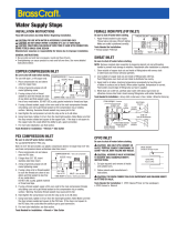
Piezas de repuesto
*Especicar acabado
Muchos cartuchos de repuesto, aireadores y
ensamblajes de drenaje pueden comprarse en
tu tienda de The Home Depot local o por internet
en WWW.HOMEDEPOT.COM
Las etiquetas de identicación
del grifo pueden encontrarse
al retirar la llave.
Pieza Descripción Número de Pieza
1 RP38046*
2 Brazo de la ducha RP38047*
3 Cabezal de la ducha RP38306*
4 Aro tórico RP60101
5 Cartucho RP20075
6 Tuerca del bonete RP7043701
7 Aro tórico RP60091
8 Funda RP80553*
9 Invertidor RP70559
Brida de la ducha
Pieza Descripción Número de Pieza
10 Tornillo RP70560
11 Placa protectora RP80554*
12
Tornillo de la
placa protectora
RP50190*
13 Llave RP13469*
14 Tornillo de jación RP50002
15 Índice RP10055
16 Tapón RP70365
17 Caño RP33073*
14
13
12
16
3
2
1
7
6
5
4
10
9
8
11
15
17

¿Problemas, preguntas o piezas faltantes?
Antes de regresar a la tienda, llama al servicio al cliente de
Glacier Bay de lunes a viernes entre 8 a.m. y 7 p.m. y los
sábados entre 9 a.m. y 6 p.m.(hora estándar del Este)
1-855-HD-GLACIER (1-855-434-5224)
HOMEDEPOT.COM/GLACIERBAY
Conserva este manual para uso futuro.
-
 1
1
-
 2
2
-
 3
3
-
 4
4
-
 5
5
-
 6
6
-
 7
7
-
 8
8
-
 9
9
-
 10
10
-
 11
11
-
 12
12
-
 13
13
-
 14
14
-
 15
15
-
 16
16
-
 17
17
-
 18
18
-
 19
19
-
 20
20
-
 21
21
-
 22
22
-
 23
23
-
 24
24
-
 25
25
-
 26
26
-
 27
27
-
 28
28
-
 29
29
-
 30
30
-
 31
31
-
 32
32
-
 33
33
-
 34
34


Glacier Bay 301879838 Guía de instalación
- Categoría
- Artículos sanitarios
- Tipo
- Guía de instalación
En otros idiomas
Documentos relacionados
-
Glacier Bay HD833CX-0027D Guía de instalación
-
-
-
-
-
-
-
-
-
Otros documentos
-
SharkBite K23036ZC2 Guía de instalación
-
DANCO 10773 Instrucciones de operación
-
Brass Craft CR1901LRX R1 Guía de instalación
-
 BrassCraft G2PS04X C1 Guía de instalación
-
 BrassCraft G2CR14X C1 Guía de instalación
-
HDX 107045 Guía de instalación
-
BrassCraft G2CR09X C1 Guía de instalación
-
-
EZ-FLO 10562 Guía de instalación
-

