LG DLEX8500V El manual del propietario
- Categoría
- Secadoras
- Tipo
- El manual del propietario
Este manual también es adecuado para

Life's Good
....._' E N °A
....... y V __ _,
DR ER
Please read this owner's manual ?horoughly before operating and
keep it handy for reference at all ?ime_
DLEXS5OO* DLGXS501 *
P/No. : MFL67731015

2 TABLE OF CONTENTS
TABLE OF CONTENTS
3 IMPORTANT SAFETY INSTRUCTIONS
3
4
4
5
5
6
7
WHAT TO DO IF YOU SMELL GAS
BASIC SAFETY PRECAUTIONS
CALIFORNIA SAFE DRINKING WATER AND TOXIC
ENFORCEMENT ACT
GROUNDING INSTRUCTIONS
SAFETY INSTRUCTIONS FOR INSTALLATION
SAFETY INSTRUCTIONS FOR STEAM FUNCTIONS
SAFETY INSTRUCTIONS FOR CONNECTING
ELECTRICITY
(3 SPECIAL FEATURES
9 INTRODUCING YOUR DRYER
9 Parts
9 Accessories
10 Control panel features
11 Time and status display
12 INSTALLATION INSTRUCTIONS
12 Installation steps
13 Installation location requirements
13 Clearances
15 Installation with optional pedestal base or stacking
kit
16 Leveling the dryer
17 To remove the door
18 To install the door
19 Changing the dryer vent location
20 Venting requirement
22 Connecting gas dryers
24 Connecting electric dryers
29 Special requirements for manufactured or mobile
homes
29 Final installation check
30 Installation test (Exhaust check)
32 HOW TO USE
32 Operating the dryer
33 Cycle guide
34 Sorting load
34 Loading the dryer
34 Check the lint filter before every load
35 Cycle setting buttons
36 Special functions
37 Custom program
37 Steam functions
39 Steam cycle guide
40 Before using the Tag On function
40 The Tag On icon
41 Tag On
43 MAINTENANCE
43 Regular cleaning
44
44
46
TROUBLESHOOTING
Before callingfor service
SPECIFICATIONS
47 USING SMARTDIAGNOSIS TM
48
48
5O
OPTIONAL ACCESSORIES
Stacking kit installation
WARRANTY

IMPORTANT SAFETY INSTRUCTIONS 3
IMPORTANT SAFETY INSTRUCTIONS
READ ALL INSTRUCTIONS BEFORE USE
AWARNING
For your safety, the information in this manual must be followed to minimize the risk of fire or explosion, electric shock, or to prevent
property damage, injury to persons, or death.
Your Safety and the safety of others it is very important.
Alehave provided many important safety messages in this manual and on your appliance. Always read and obey all safety messages.
This is the safety alert symbol.
This symbol alerts you to potential hazards that can kill or hurt you and others.
All safety messages will follow the safety alert symbol and either the word DANGER, WARNING or CAUTION.
These words mean:
ADANGER
You will be killed or seriously injured if you don't immediately follow instructions.
AWARNING
You can be killed or seriously injured if you don't follow instructions.
ACAUTION
You may be slightly injured or cause damage to the product if you do not follow instructions.
All safety messages will tell you what the potential hazard is,tell you how to reduce the chance of injury, and tell you what can happen if
the instructions are not followed.
• Do not install a clothes dryer with flexible plastic venting materials. If flexible metal (foil type) duct isinstalled, it must be of
aspecific type identified bythe appliance manufacturer as suitable for usewith clothes dryers. Flexible venting materials are
known to collapse, be easily crushed, and trap lint. These conditions will obstruct clothes dryer airflow and increase the risk of
fire.
• Do not store or usegasoline or other flammable vapors and liquids in the vicinity of this appliance or any other appliances.
• Installation and service must be performed by aqualified installer, service agency, or the gassupplier.
• Install the clothes dryer according to the manufacturer's instructions and local codes.
• Save these instructions.
WHAT TO DO IF YOU SMELL GAS:
1.Do not try to light a match or cigarette, or turn on any gas or electrical appliance.
2. Do not touch any electrical switches. Do not use any phone in your building.
3. Clear the room, building, or area of all occupants.
4. Immediately call your gas supplier from a neighbor's phone. Follow the gassupplier's instructions carefully.
S.If you cannot reach your gas supplier, call the fire department.
AWARNING
This product contains chemicals known to the State of California to cause cancer and birth defects or other reproductive harm.
Washhandsafter handling.

4 IMPORTANT SAFETY INSTRUCTIONS
IMPORTANT SAFETY INSTRUCTIONS
READ ALL INSTRUCTIONS BEFORE USE
AWARNING
For your safety, the information in this manual must be followed to minimize the risk of fire or explosion, electric shock, or to prevent
property damage, injury to persons, or death.
BASIC SAFETY PRECAUTIONS
AWARNING
To reduce the risk of fire, electric shock, or injury to persons when using this appliance, follow basic precautions, including the following:
. Read all instructions before using the dryer.
. Before use, the dryer must be properly installed as described in
this manual.
. Do not place items exposed to cooking oils in your dryer. Items
contaminated with cooking oils may contribute to a chemical
reaction that could cause a load to catch fire.
, Do not dry articles that have been previously cleaned in, washed
in, soaked in, or spotted with gasoline, dry-cleaning solvents, or
other flammable or explosive substances as they give off vapors
that could ignite or explode.
. Do not reach into the dryer if the drum or any other part is
moving.
, Do not repair or replace any part of the dryer or attempt any
servicing unless specifically recommended in this Use and Manual
or in published user-repair instructions that you understand and
have the skills to carry out.
. Do not tamper with controls.
. Before the dryer is removed from service or discarded, remove the
door to the drying compartment.
, Do not allow children to play on or in the dryer. Close supervision
of children is necessary when the dryer is used near children.
.Do not use fabric softeners or products to eliminate static unless
recommended by the manufacturer of the fabric softener or
product.
. Do not use heat to dry articles containing foam rubber or
similarly textured rubber-like materials.
. Keep area around the exhaust opening and adjacent surrounding
areas free from the accumulation of lint, dust, and dirt.
, The interior of the dryer and exhaust vent should be cleaned
periodically by qualified service personnel.
, Do not install or store the dryer where it will be exposed to the
weather.
.Always check the inside of the dryer for foreign objects.
. Clean lint screen before or after each load.
. Do not store plastic, paper, or clothing that may burn or melt
on top of the dryer during operation.
CALIFORNIA SAFE DRINKING WATER AND TOXIC ENFORCEMENT ACT
This act requires the governor of California to publish a list of substances known to the state to cause cancer, birth defects, or other
reproductive harm and requires businesses to warn customers of potential exposure to such substances.
Gas appliances can cause minor exposure to four of these substances, namely benzene, carbon monoxide, formaldehyde, and soot, ca used
primarily by the incomplete combustion of natural gas or LP fuels.
Properly adjusted dryers will minimize incomplete combustion. Exposure to these substances can be minimized further by properly
venting the dryer to the outdoors.

IMPORTANT SAFETY INSTRUCTIONS 5
IMPORTANT SAFETY INSTRUCTIONS
READ ALL INSTRUCTIONS BEFORE USE
AWARNING
For your safety,the information in this manual must be followed to minimize the risk of fire or explosion, electric shock, or to prevent
property damage, injury to persons, or death.
GROUNDING INSTRUCTIONS
This appliance must be grounded. In the event of malfunction
or breakdown, grounding will reduce the riskof electric shock
by providing a path of least resistance for electric current. This
appliance must be equipped with a cord having an equipment-
grounding conductor and agrounding plug. The plug must be
plugged into an appropriate outlet that is properly installed and
grounded in accordance with all local codes and ordinances.
Do not modify the plug provided with the appliance. If it will not fit
the outlet, have a proper outlet installed by a qualified electrician.
This appliance must be connected to a grounded metal, permanent
wiring system or an equipment-grounding conductor must be
run with the circuit conductors and connected to the equipment-
grounding terminal or lead on the appliance.
Electric shock can result if the dryer is not properly grounded.
AWARNING
Improper connection of the equipment-grounding conductor can result in a riskof electric shock. Checkwith a qualified electrician or
service person if you arein doubt that the appliance isproperly grounded.
SAFETY INSTRUCTIONS FOR INSTALLATION
AWARNING
Toreduce the risk of fire, electric shock, or injury to persons when using this appliance, follow basic precautions, including the following:
. Properly ground dryer to conform with all governing codes
and ordinances. Follow details in the installation instructions.
Electric shock can result if the dryer is not properly grounded.
. Before use, the dryer must be properly installed asdescribed
in this manual. Electric shock can result if the dryer is not properly
grounded.
. Install and store the dryer where it will not be exposed to
temperatures below freezing or exposed to the weather.
. All repairs and servicing must be performed by an authorized
servicer unlessspecifically recommended in this Owner's
Manual. Useonly authorized factory parts. Failure to follow this
warning can cause serious injury, fire,electric shock, or death.
. To reduce the risk of electric shock, do not install the dryer in
humid spaces. Failureto follow this warning can causeserious
injury, fire,electric shock, or death.
. Connect to aproperly rated, protected, and sized power
circuit to avoid electrical overload. Improper power circuit can
melt, creating electric shock and/or fire hazard.
. Remove all packing items and dispose of all shipping
materials properly. Failureto do so can result in death, explosion,
fire, or burns.
. Place dryer at least 18 inchesabove the floor for a garage
installation. Failureto do so can result in death, explosion, fire, or
burns.
, Keep all packaging from children. Packaging material can be
dangerous for children. There isa riskof suffocation.
. Do not install near another source of heat suchas astove,
cooking oven. Failure to do socan cause deform, smoke and fire.
. Do not place candles, smoking materials, or other flammables
on top of the product. Dripping wax, smoke, or fire can result.
. Remove all protective vinyl film from the product. Failure to do
socan causeproduct damage, smoke or fire.

6 IMPORTANT SAFETY INSTRUCTIONS
IMPORTANT SAFETY INSTRUCTIONS
READ ALL INSTRUCTIONS BEFORE USE
AWARNING
For your safety,the information in this manual must be followed to minimize the risk of fire or explosion, electric shock, or to prevent
property damage, injury to persons, or death.
SAFETY INSTRUCTIONS FOR INSTALLATION
AWARNING
Toreduce the risk of injury to persons, follow all industry recommended safety procedures including the use of long sleeved gloves and
safety glasses. Failureto follow all of the safety warnings in this manual could result in property damage, injury to persons or death.
Exhaust/Ducting:
. Gas dryers MUST be exhausted to the outside. Failure to follow
these instructions can result in fire or death.
. The dryer exhaust system must be exhausted to the outside of
the dwelling. If the dryer isnot exhausted outdoors, some fine
lint and large amounts of moisture will be expelled into the
laundry area. An accumulation of lint in any area of the home can
create a health and fire hazard.
. Useonly rigid metal or flexible metal 4-inch diameter
ductwork inside the dryer cabinet or for exhausting to the
outside. Use of plastic or other combustible ductwork can
cause a fire. Punctured ductwork can causea fire if it collapses or
becomes otherwise restricted in use or during installation.
. Ductwork isnot provided with the dryer, and you should
obtain the necessary ductwork locally. The end cap should
have hinged dampers to prevent backdraft when the dryer is
not in use. Failure to follow these instructions can result in fire or
death.
. The exhaust duct must be 4 inches(10.2 cm) in diameter with
no obstructions. The exhaust duct should be kept as short as
possible. Make sure to clean any old ducts before installing
your new dryer. Failure to follow these instructions can result in
fire or death.
. Rigid or semi-rigid metal ducting isrecommended for use
between the dryer and the wall. In special installations
when it is impossible to make a connection with the above
recommendations, aUUlisted flexible metal transition duct
may be used between the dryer and wall connection only.
The useof this ducting will affect drying time. Failureto follow
these instructions can result in fire or death.
. DO NOT usesheet metal screwsor other fasteners which
extend into the duct that could catch lint and reduce the
efficiency of the exhaust system. Secureall joints with duct tape.
For complete details, follow the Installation Instructions. Failure to
follow these instructions can result in fire or death.
SAFETY INSTRUCTIONS FOR STEAM FUNCTIONS
AWARNING
Toreduce the risk of fire, electric shock, or injury to persons when using this appliance, follow basic precautions, including the following:
. Do not open the dryer door during steam cycles. Failureto
follow these instructions can result in a burn hazard.
. Do not dry articles that have been previously cleaned in,
washed in, soaked in, or spotted with gasoline, dry-cleaning
solvents, or other flammable or explosive substances asthey
give off vapors that could ignite or explode. Failureto follow
these instructions can result in fire or death.
. Do not fill the steam feeder with gasoline, dry-cleaning
solvents, or other flammable or explosive substances. Failure
to follow these instructions can result in fire or death.
. Do not touch the steam nozzle in the drum during or after the
steam cycle. Failureto follow these instructions can result in a
burn hazard.
. Do not fill the steam feeder with hot water (over 86 °F/30 °C).
Failure to follow these instructions can result in a burn hazard.

IMPORTANT SAFETY INSTRUCTIONS 7
IMPORTANT SAFETY INSTRUCTIONS
READ ALL INSTRUCTIONS BEFORE USE
AWARNING
For your safety, the information in this manual must be followed to minimize the risk of fire or ex
property damage, injury to persons, or death.
_losion, electric shock, or to prevent
SAFETY INSTRUCTIONS FOR CONNECTING ELECTRICITY
AWARNING
To reduce the risk of fire, electric shock, or injury to persons when using this appliance, follow basic precautions, including the following:
. Do not, under any circumstances, cut or remove the ground
prong from the power cord. To prevent injury to persons or
damage to the dryer, the electrical power cord must be plugged
into a properly grounded outlet.
. For personal safety, this dryer must be properly grounded.
Failure to do so can result in electric shock or injury.
. Refer to the installation instructions in this manual for specific
electrical requirements for your model. Failure to follow these
instructions can create an electric shock hazard and/or a fire
hazard.
. This dryer must be plugged into a properly grounded outlet.
Electric shock can result if the dryer is not properly grounded.
Have the wall outlet and circuit checked by a qualified
electrician to make sure the outlet is properly grounded.
Failure to follow these instructions can create an electric shock
hazard and/or a fire hazard.
. The dryer should always be plugged into its own individual
electrical outlet which has a voltage rating that matches
the rating plate. This provides the best performance and also
prevents overloading house wiring circuits which could cause a
fire hazard from overheated wires.
. Never unplug your dryer by pulling on the power cord. Always
grip plug firmly and pull straight out from the outlet. The
power cord can be damaged, resulting in a risk of fire and electric
shock.
. Repair or replace immediately all power cords that have
become frayed or otherwise damaged. Do not usea cord that
shows cracks or abrasion damage along its length or at either
end. The power cord can melt, creating an electric shock and/or
fire hazard.
. When installing or moving the dryer, be careful not to pinch,
crush, or damage the power cord. This will prevent injury and
prevent damage to the dryer from fire and electric shock.
SAVE THESE INSTRUCTIONS

8 SPECIAL FEATURES
SPECIAL FEATURES
The ultra-large stainless steel drum offers superior durability.
The wide-opening door provides easy access for loading and unloading. The door hinge can be reversed to adjust for installation location.
LG's steam technology allows you to inject fabrics with a swirling jet of hot steam to refresh clothes, reduce static, simplify ironing and
assist in the removal of lightly stained spots. Simply select the STEAM FRESHTM or SpotClean TM cycle, oryou can add a Steam option to
select cycles.
Should you experience any technical difficulty with your dryer, it has the capability of transmitting data via your telephone to the
Customer Information Center. The call center agent records the data transmitted from your machine and uses it to analyze the issue,
providing a fast and effective diagnosis.
The FLOW SENSETM duct blockage sensing system detects and alerts you to restrictions in the installed household ductwork that reduce
exhaust airflow through the dryer. If you see the alert: Clean or repair the ducts to remove the restrictions. Keep your ducts clean to help
increase efficiency and reduce long drying times caused by blocked ducts.
Rotate the cycle selector knob to select the desired dry cycle. Add cycle options or adjust settings with the touch of a button.
The easy-to-read LCD screen shows cycle options and information and provides status messages during operation.
The Tag On function allows you to use most NFC-equipped, And roid-based smart phones to communicate with your appliance.
Once you download the LG Smart Laundry&DW application to your phone, you can download and install new laundry cycles on
your appliance with Tag On Cycle Download or help diagnose issues with Tag On Diagnosis. (Refer to pages 40-42)
Protocol P154
Sanitization Performance of
Residential Clothes dryer

INTRODUCING YOUR DRYER
INTRODUCING YOUR DRYER
Parts
Control panel
Leveling feet
Reversible
door
Power Cord
Location
(Gas Models)
Gas
Connection
Location
(Gas Models)
-- Terminal Block
Access Panel
(Electric
Models)
Exhaust Duct
Outlet
Accessories
Included Accessories
Drying Rack
Optional Accessories
Pedestal Stacking Kit
(sold separately) (sold separately)
--@NOTE --,
• Contact LG Customer Service at 1-800-243-0000 (1-888-542-2523 in Canada) if any accessories are missing.
• For your safety and for extended product life, use only authorized components. The manufacturer is not responsible for product I
malfunction or accidents caused by the use of separately purchased unauthorized components or parts. /
•The images in this Manual may be different from the actual components and accessories, and are subject to change by the manufactureq
without prior notice for product improvement purposes. ./

]O INTRODUCING YOUR DRYER
Control panel features
4BWARNING: To reduce the risk of fire, electric shock, or injury to persons, read this entire manual,
including the important Safety Instructions, before operating this dryer.
Cycle Selector Knob
Jumbo Dry
_,'ool
Air Dry
Display LCD
Power Button
Operation
Start/Pause Dry Level Temp. Time Dry Signal
Button Button Control Button Button
Button
Cotton/N0rmal Jumbo Dry
Perm.Press Delicates
Heavy Duty Wool
Towels Spot Clean
AntiB .........Cyc!_
• Power On/Off Button
- Press to turn the dryer ON or OFF. Pressing the Power button during a cycle will cancel that cycle and any
settings will be lost.
* CYCLE SELECTOR KNOB
-Turn this knob to select the desired cycle. Once the desired cycle has been selected, the standard presets
will be shown in the display. On MANUAL DRY cycles, these settings can be adjusted using the cycle setting
buttons anytime before starting the cycle.
Start/Pause Button
- Press this button to START the selected cycle. If the dryer isrunning, use this button to Pause the cycle
without losing the current settings.
NOTE : If you do not press the Start/Pause Button to resume a cycle within 4 minutes, the dryer turns off
automatically.
* ,More Time / Less Time Button
-To adjust the drying time, use these buttons with Manual Dry, Time Dry, and Steam Fresh TM cycles, as well as
the Reduce Static and Easy Iron options. Press the More Time Button to increase the selected manual cycle
time by a minute; press Less Time to decrease the cycle time by a minute.
* CYCLE SETTING BUTTONS
- Use these buttons to adjust the settings for the selected cycle.
• OPTION BUTTONS
-The OPTION buttons allow you to select additional cycle options. Not all settings are available for all cycles.
Refer to the CYCLE GUIDE section of the manual.
• STEAM FUNCTIONS
- LG'ssteam technology allows you to inject fabrics with a swirling jet of hot steam to refresh clothes, reduce
static, and make ironing easier. Simply select the Steam Fresh TM cycle, or add a STEAM option to the selected
cycles.

INTRODUCINGYOURDRYER11
Time and status display
Time and status display shows the settings, estimated time remaining, options, and status
messages for your dryer. When the dryer is turned on, the light in the display will illuminate.
AddHater
0:41!
Normal Medium 40(tVllN) High
DispHay icon Description
o • STATUS/CYCLE DISPLAY
rylng -This portion of the display shows the selected cycle, operating status, and special messages. If a cycle has
special instructions, they will also be displayed in this area.
0:41!
20%
ira-
lChiidLockJ
JAddHater
• ESTIMATEDTIME REMAINING
-When the START/PAUSE button is pressed, the dryer will display the estimated (SENSOR DRY) or set time
(TIME DRY) remaining, and begin tumbling.
NOTE : The cycle time on SENSOR DRY cycles may fluctuate as the dryer recalculates drying time for optimal
results.
• CYCLE SETTING INDICATORS
-These indicators show the current cycle settings for DRY LEVEL, TEMR CONTROL, TIME DRY, and Damp Dry
Signal.To change these settings, press the appropriate settings button.
• CYCLECOMPLETION INDICATOR
- Shows how much of the current drying cyclehas been completed.
• CHILD LOCK INDICATOR
-When CHILD LOCK is set, the Child Lock indicator will appear and all buttons are disabled except the ON/
OFF button.This prevents children from changing settings while the dryer is operating.
• DRUM LIGHT INDICATOR
- During operating cycle, you can see the drum inside by choosing drum light function.
It helps easy viewing the drying cycle.
• ADDWATER INDICATOR
- If the steam feeder islack for water, this indicatorwill appear. Fill the feeder and restart the cycle.

12 INSTALLATION INSTRUCTIONS
INSTALLATION INSTRUCTIONS
Insfallafion sfeps
\\\: .....
:j ........................
Checking and choosing
the proper location
Leveling the dryer Venting the Dryer
Connecting Gas Dryers
(Gas Dryer Type)
Plugging in the power
cord and grounding
Exhaust check test
(Refer to page 30.)
Test run

INSTALLATIONINSTRUCTIONS13
JnsfalJafion Jocafion requiremenfs
AWARNING
Read all installation instructions completely before installing and operating your dryer! It is important that you review this entire
manual before installing and using your dryer. Detailed instructions concerning electrical connections, gas connections, and exhaust
requirements are provided on the following pages.
, A location that allows for proper exhaust installation. A
gas dryer must be exhausted to the outdoors. See Venting
Requirements(R20).
. A grounded electrical outlet located within 2 ft. (61 cm) of either
side of the dryer. See Electrical Requirements(Pc24).
, A sturdy floor to support the total dryer weight of 200 Ibs (90.7
kg).The combined weight of a companion appliance should also
be considered.
, No other fuel-burning appliance can be installed in the same
closet as a dryer.
Do not operate your dryer at temperatures below 45°F (7°C). At lower temperatures, the dryer might not shut off at the end of an automatic
cycle. This can result in longer drying times. The dryer must not be installed or stored in an area where it will be exposed to water and/or
weather. Check code requirements. Some codes limit, or do not permit, installation of the dryer in garages, closets, mobile homes or
sleeping quarters. Contact your local building inspector.
NOTE .................................................................................................................................................................................................................................................................................................................................................................................................................................................................................................................................................................................................................................................................................................................................................................................................................................................................,,
• A level floor with a maximum slope of 1 inch (2.5 cm) under entire dryer. If slope is greater than 1 inch (2.5 cm), install the Extended
Dryer Feet Kit. Clothes may not tumble properly, and automatic sensor cycles may not operate correctly if d ryer is not level. I
• For a garage installation, you will need to place the dryer at least 18 inches (46 cm) above the floor. If using a pedestal, you will need I
/ 18 inches (46 cm) to the bottom of the dryer.
Clearances
J0_ |35.6 cm) 10tJ (35'6cm) 48 in.2*
"_-_======= mm.* (310 cm2)
18" rain.* _m_ i
I (45.7 cm)
24 in.2__
(155cm2)
Jl"*_ 32.1" _'JS"**J 1"*11_ 32.1" ÷15"**1
(2,5cm) (81,4cm) (12,7cm) (2,5cm) (81,4cm) (12.7crn)
(7,6 cm)
Closet Door Vent
Requirements
INSTALLATION SPACING FOR RECESSED AREA OR CLOSET INSTALLATION
The following spacing dimensions are recommended for this dryer. This dryer has been tested for spacing of 1 inches(2.Scm) clearance on
the sides and rear. Recommended spacing should be considered for the following reasons:
. Additional spacing should be considered for ease of installation
and servicing.
, Additional clearances might be required for wall, door and floor
moldings.
, Additional spacing should be considered on all sides of the dryer
to reduce noise transfer.
For closet installation, with a door, minimum ventilation openings
in the top and bottom of the door are required. Louvered doors
with equivalent ventilation openings are acceptable.
Companion appliance spacing should also be considered.
NOTE .................................................................................................................................................................................................................................................................................................................................................
There should be at least a little space around the dryer (or any other appliance) to eliminate the transfer of vibration from one to the I
other. Too much vibration could cause the appliances to touch each other, causing paint damage and more noise, i
J

14 INSTALLATION INSTRUCTIONS
Installation location requirements (Cont.)
AWARNING
Read all installation instructions completely before installing and operating your dryer! It is important that you review this entire
manual before installing and using your dryer. Detailed instructions concerning electrical connections, gas connections, and exhaust
requirements are provided on the following pages.
, A location that allows for proper exhaust installation. A
gas dryer must be exhausted to the outdoors. See Venting
Requirements(R20).
. A grounded electrical outlet located within 2 ft. (61 cm) of either
side of the dryer. See Electrical Requirements(Po24).
, A sturdy floor to support the total dryer weight of 200 Ibs (90.7
kg).The combined weight of a companion appliance should also
be considered.
, No other fuel-burning appliance can be installed in the same
closet as a dryer.
Do not operate your dryer at temperatures below 45% (7°C). At lower temperatures, the dryer might not shut off at the end of an automatic
cycle. This can result in longer drying times. The dryer must not be installed or stored in an area where it will be exposed to water and/or
weather. Check code requirements. Some codes limit, or do not permit, installation of the dryer in garages, closets, mobile homes or
sleeping quarters. Contact your local building inspector.
Clearances (Space for Using the Dryer.)
If the duct is installed in the wall. If the duct isn't installed in the wall.
i
59"
(151.8 cm)
59"
(151.8 cm)
\
(12.7 cm)

INSTALLATION INSTRUCTIONS 15
Insfallafion wifh opfional pedesfal base or slacking kif
RECOMMENDED INSTALLATION SPACING FOR CABINET INSTALLATION
. For cabinet installation with a door, minimum ventilation openings in the top of the cabinet are required.
*Required spacing
**For side or bottom venting,
2 inches (5.1 cm) spacing is allowed.
7"*(17.8 cm) ,J_* (17,8cm)
_ 9....
(22.9 cm)
j 5.... 32,1" 1.... 1" 29" 1"
(12.7cm) (81,4cm) (2.5cm) (2.5cm)(73.6 cm) (2.5 cm)
CLOSET VENTILATION REQUIREMENTS
Closets with doors must have both an upper and lower vent to prevent heat and moisture buildup in the closet. One upper vent opening
with a minimum opening of 48 sq. in. (310 cm 2) must be installed no lower than 6 feet above the floor. One lower vent opening with a
minimum opening of 24 sq. in. (155 cm 2) must be installed no more than one foot above the floor. One example shown uses vent grilles in
the door.
RECOMMENDED INSTALLATION SPACING FOR RECESSED OR CLOSET INSTALLATION, WITH STACKED WASHER AND DRYER
. The dimensions shown are for the recommended spacing.
*Required spacing
**For side or bottom venting,
2 inches (5.1 cm) spacing is allowed.
48 iN, 2 * ,,*
(310 cm2) 3;(7.6
ore)
24 in.2 *
(155cm2)
m
U U
_- 1"* (2.5 cm)
i i! i_,"
!!!i!!
!!!!!!
5 _.**
(14 cm)
6"*(15.2cm)
!_
81.6"
(207.2 cm)
1,,-_,- I,,_--29,,_=,.-
(2.5 cm) (73.6 era)
(2.5 cm)

16 INSTALLATION INSTRUCTIONS
Leveling fhe dryer
AWARNING
• To reduce the risk of injury to persons, adhere to all industry
recommended safety procedures including the use of
long sleeved gloves and safety glasses. Failure to follow this
warning can cause serious injury or death.
• The appliances are heavy. Two or more people are required
when installing the dryer. Failure to follow this warning can
cause serious injury or death.
To ensure that the dryer provides optimal drying performance,
it must be level.To minimize vibration, noise, and unwanted
movement, the floor must be a perfectly level, solid surface.
@ NOTE -,
Adjust the leveling feet only as far as necessary to level the
dryer. Extending the leveling feet more than necessary can
.c aU!_e[.be dryer to vibra!e:_ ..................................................................................................................................................................................................
1. Position the dryer in the final location. Place a level across the
top of the dryer.
2. Use an adjustable wrench to turn the leveling feet.Turn
clockwise to raisethe dryer or counterclockwise to lower it.
Raiseor lower the leveling feet until dryer is level from side to
side and front to back.
Make surethat all 4 leveling feet are in firm contact with the floor.
Leveling Feet
. All four leveling feet must rest solidly on the floor. Gently push
on the top corners of the dryer to make sure that the dryer does
not rock from corner to corner.
Ifyou areinstalling the dryer on the optional pedestal, you must
use the leveling feet on the pedestal to level the dryer.The dryer
leveling feet should be fully retracted.

INSTALLATION INSTRUCTIONS 17
To remove fhe door
:..AWARNING .....................................................................................................................................
• To avoid damage to the dryer or the door, support the
door with a stool or box that fits under the door, or have
an assistant support the weight of the door.
• Always reverse the door BEFORE stacking the dryer on top
of the washer.
• Avoid dropping the door to avoid damage to the door or
the floor.
THE DRYER DOOR ISVERY LARGE AND HEAVY. Failure to follow
the instructions below can result in damage to the dryer,
property damage or injury to persons.
.......................................................................................................................................................................................................................................................................................J
1. Open the door to reverse.
4. Remove two screws and disassembly Latch.
Latch Screw
5. Hold on the hinge while remove 2 screws of hinge (to prevent
door dropping).
<", Hinge
6. Remove door from cabinet cover.
@
@
3. Remove four dummy screws by driver.
_, /_ Hinge
.........!,,,,{ Dummy
Screw

'18 INSTALLATION INSTRUCTIONS
To install the door
,,,AWARNING ..........................................................................................................................................................
• To avoid damage to the dryer or the door, support the
door with a stool or box that fits under the door, or have
an assistant support the weight of the door.
• Always reverse the door BEFORE stacking the dryer on top
of the washer.
• Avoid dropping the door to avoid damage to the door or
the floor.
THE DRYER DOOR IS VERY LARGE AND HEAVY. Failure to follow
the instructions below can result in damage to the dryer,
property damage or injury to persons.
.......................................................................................................................................................................................................................................................................................J
4. Screw down four dummy screws right side.
o _ Hinge
Dummy
Screw
o
1. Move door to left side and insert a hinge to hinge hole.
.... _l /,,#"
.....2/:: Hinge hole
i
J
I
i,o
%::.... : _,
5. Check that the door closes and latches properly.
2. Hold on hinge while screw down a hinge
(to prevent door dropping).
\
Hinge Screw
/
ii
3. Insert latch to right side and install screws.
'Y :/
4/
Latch
Screw
_d

INSTALLATION INSTRUCTIONS ]9
Changing fhe dryer venf Iocafion
.....AWARNING ...................................................................................................................................................................................................................................................................................
• Use a heavy metal vent.
• Do not use plastic or thin foil duct.
• Clean old ducts before installing this dryer.
• To reduce the risk of injury to persons adhere to all
industry recommended safety procedures including the
use of long sleeved gloves and safety glasses.
, Failure to follow all of the safety warnings in this manual could
result in property damage, injury to person or death.
Your new dryer is shipped to vent to the rear.
It can also be configured to vent to the bottom or side (right-
side venting is not available on gas models).
An adapter kit, part number 383EEL9001 L, may be purchased
from your LG retailer.This kit contains the necessary duct
components to change the dryer vent location.
1. Remove the rear exhaust duct retaining screw. Pull out the
exhaust duct.
f
Retaining
Rear
Exhaust Duct
Preassemble a 4 inches (10.2 cm) elbow to the next 4-inches
(10.2 cm) duct section, and secure all joints with duct tape. Be
sure that the male end of the elbow faces AWAY from the dryer.
Insert the elbow/duct assembly through the side opening and
press it onto the adapter duct. Secure in place with duct tape.
Be sure that the male end of the duct protrudes 11/2inches (3.8
cm) to connect the remaining ductwork.
Attach cover plate to the back of the dryer with included screw.
Plate
11/21'
(3.8 cm)
OPTION 2: BOTTOM VENTING
2. Press the adapter duct onto the blower housing and secure to
the base of the dryer as shown.
Adapter
Bracket
OPTION 1: SIDE VENTING
2. Press the tabs on the knockout and carefully remove the
knockout for the desired vent opening (right-side venting is
not available on gas models). Press the adapter duct onto the
blower housing and secure to the base of the dryer as shown.
Adapter
3. Insert the 4 inches (10.2 cm) elbow through the rear opening
and press it onto the adapter duct. Be sure that the male end of
the elbow faces down through hole in the bottom of the dryer.
Secure in place with duct tape.
Attach the cover plate to the back of the dryer with included
screw.
\\
Plate
Knockout

20 INSTALLATION INSTRUCTIONS
Venfing requiremenf
AWARNING
To reduce the risk of fire, electric shock, or injury to persons when using this appliance, follow basic precautions, including the following:
. Do not crush or collapse ductwork. Failure to follow these
instructions can result in fire or death.
. Do not allow ductwork to rest on or contact sharp objects.
Failure to follow these instructions can result in fire or death.
. If connecting to existing ductwork, make sure it is suitable
and clean before installing the dryer. Failure to follow these
instructions can result in fire or death.
. Venting must conform to local building codes. Failure to follow
these instructions can result in fire or death.
. Gas dryers MUST exhaust to the outdoors.
Failure to follow these instructions can result in fire or death.
. Use only 4-inch (10.2 cm) rigid or flexible metal ductwork
inside the dryer cabinet and for venting outside. Failure to
follow these instructions can result in fire or death.
. To reduce the risk of fire, combustion, or accumulation of
combustible gases, DO NOT exhaust dryer air into an enclosed
and unventilated area, such as an attic, wall, ceiling, crawl
space, chimney, gas vent, or concealed space of a building.
Failure to follow these instructions can result in fire or death.
. To reduce the risk of fire, DO NOT exhaust the dryer with
plastic or thin foil ducting.
Failure to follow these instructions can result in fire or death.
. The exhaust duct must be 4 inches (10.2 cm) in diameter with
no obstructions. The exhaust duct should be kept as short as
possible. Make sure to clean any old ducts before installing
your new dryer. Failure to follow these instructions can result in
fire or death.
Rigid or semirigid metal ducting is recommended for use
between the dryer and the wall. In special installations
when it is impossible to make a connection with the above
recommendations, a UUlisted flexible metal transition duct
may be used between the dryer and wall connection only.
The use of this ducting will affect drying time. Failure to follow
these instructions can result in fire or death.
DO NOT use sheet metal screws or other fasteners which
extend into the duct that could catch lint and reduce the
efficiency of the exhaust system. Secure all joints with duct
tape. Failure to follow these instructions can result in fire or death.
To maximize operating results, please observe the duct length
limitations noted in the chart next page. Failure to follow these
instructions can result in fire or death.
Ductwork isnot provided with the dryer. Youshould obtain
the necessary ductwork locally. The end cap should have
hinged dampers to prevent backdraft when the dryer isnot in
use. Failureto follow these instructionscan result in fire or death.
The Total length of flexible metal duct shall not exceed 8 ft.
(2.4 m)
In Canada, that only those foil-type flexible ducts, if any,
specifically identified for usewith the appliance by the
manufacturer shall be used. In the United States,that only those
foil-type flexible ducts, if any, specifically identified for usewith
the appliance by the manufacturer and that comply with the
Outline for Clothes DryerTransition Duct, Subject 2158A, shall be
used.

INSTALLATION INSTRUCTIONS 21
Venting requirement
Ductwork
Recommended
(10.2 cm)
(10.2 cm)
Use Only for Short
Run Installations
(6.35 cm)
0
I
2
3
4
0
I
2
3
4
65 ft. (19.8 m)
55 ft. (16.8 m)
47 ft. (14.3 m)
36 ft. (I 1.0m)
28 ft. (8.5 m)
55 ft. (16.8 m)
47 ft. (14.3 m )
41 ft. (12.5 m)
30 ft. (9.1 m)
22 ft. (6.7 m)
1/
@ NOTE ....-,
Deduct 6 ft. (I .8 m) for each additional elbow. It is not recommended I
to use more than four 90° elbows.
ROUTINGAND CONNECTINGDUCTWORK
@ NOTE
Follow the guidelines below to maximize drying performance and
reduce lint buildup and condensation in the ductwork.
Ductwork and fittings are NOT included and must be purchased
separately.
. Use 4-inch (10.2 cm) diameter rigid or semirigid metal ductwork.
. The exhaust duct run should be as short as possible.
. Use as few elbow joints as possible.
. The male end of each section of exhaust duct must point away from
the dryer.
. Use duct tape on all duct joints.
. Insulate ductwork that runs through unheated areas in order to
reduce condensation and lint buildup on duct surfaces.
° Failure to exhaust the dryer correctly will void the dryer's warranty.
J
CORRECT VENTING
!i!
.................C
I ,, t,
INCORRECTVENTING

22 INSTALLATION INSTRUCTIONS
Connecfing gasdryers
AWARNING
To reduce the risk of fire, electric shock, or injury to persons when using this appliance, follow basic precautions, including the following:
. Gas supply requirements:
As shipped from the factory, this dryer is configured for use
with natural gas. It can be converted for use with LP (Liquefied
Propane) gas. Gas pressure must not exceed 13 inches of
water column.
. A qualified service or gas company technician must connect
the dryer to the gas service.
Failure to do so can result in fire, explosion, or death.
. Isolate the dryer from the gas supply system by closing its
individual manual shutoff valve during any pressure testing
of the gas supply. Failure to do so can result in fire, explosion, or
death.
. Supply line requirements:
Your laundry room must have a rigid gas supply line to your
dryer. In the United States, an individual manual shutoff valve
MUST be installed within at least 6 ft. (1.8 m) of the dryer, in
accordance with the National Fuel Gas Code ANSI Z223.1 or
Canadian gas installation code CSA B149.1. A 1/s- inch NPT
pipe plug must be installed. Failure to do so can result in fire,
explosion, or death
. If using a rigid pipe, the rigid pipe should be 1/2- inch IPS.
If acceptable under local codes and ordinances and when
acceptable to your gas supplier, % - inch approved tubing
may be used where lengths are less than 20 ft. (6.1 m). Larger
tubing should be used for lengths in excess of 20 ft. (6.1 m).
Failure to do so can result in fire, explosion, or death.
. Connect the dryer to the type of gas shown on the nameplate.
Failure to do so can result in fire, explosion, or death.
. To prevent contamination of the gas valve, purge the gas
supply of air and sediment before connecting the gas supply
to the dryer. Before tightening the connection between the
gas supply and the dryer, purge remaining air until the odor
of gas is detected. Failure to do so can result in fire, explosion, or
death.
. DO NOT use an open flame to inspect for gas leaks. Use a
noncorrosive leak-detection fluid. Failure to do so can result in
fire, explosion, or death.
. Use only a new AGA- or CSA-certified gas supply line with
flexible stainless steel connectors. Failure to do so can result in
fire, explosion, or death.
. Securely tighten all gas connections. Failure to do so can result
in fire, explosion, or death.
. DO NOT attempt any disassembly of the dryer; any
disassembly requires the attention and tools of an authorized
and qualified service person or company. Failure to do so can
result in fire, explosion, or death.
. Use a pipe-joint compound that is insoluble in Liquefied
Petroleum (LP) gas on all pipe threads. Failure to do so can
result in fire, explosion, or death.
Electrical Requirements for Gas Models Only
AWARNING
To reduce the risk of fire, electric shock, or injury to persons when using this appliance, follow basic precautions, including the following:
. Do not, under any circumstances, cut or remove the third
(ground) prong from the power cord. Failure to follow this
warning can result in fire, explosion, or death.
. For personal safety, this dryer must be properly grounded,
Failure to follow this warning can result in fire, explosion, or death.
. The power cord of this dryer isequipped with a 3-prong
(grounding) plug which mates with a standard 3-prong
(grounding) wall outlet to minimize the possibility of electric
shock hazard from this appliance. Failure to follow this warning
can result in fire, explosion, or death.
. This dryer must be plugged into a 60 Hz, 120 VAC, grounded
outlet protected by a 1S-ampere fuse or circuit breaker. Failure
to follow this warning can result in fire, explosion, or death.
. Where a standard 2-prong wall outlet is encountered, it is your
personal responsibility and obligation to have it replaced with
a properly grounded 3-prong wall outlet. Failure to follow this
warning can result in fire, explosion, or death.

INSTALLATION INSTRUCTIONS 23
Connecfin 9 gas dryers (conf.)
AWARNING
To reduce the risk of fire, electric shock, or injury to persons when
using this appliance, follow basic precautions, including the
following:
. Installation and service must be performed by a qualified
installer, service agency, or the gas supplier. Failure to do so
can result in fire, explosion, or death.
. Use only a new stainless steel flexible connector and a new
AGA-certified connector. Failure to do so can result in fire,
explosion, or death.
. A gas shutoff valve must be installed within 6 ft. (1.8 m) of
the dryer. Failure to do so can result in fire, explosion, or death.
. The dryer is configured for Natural Gas when shipped from
the factory. Make sure that the dryer is equipped with the
correct burner orifice for the type of gas being used (Natural
Gas or Liquefied Petroleum). Failure to do so can result in fire,
explosion, or death.
. If necessary, the correct orifice (for the LP, orifice kit order
part number 383EEL3002D) should be installed by a
qualified technician and the change should be noted on the
dryer. Failure to do so can result in fire, explosion, or death.
. All connections must be in accordance with local codes and
regulations. Failure to do so can result in fire, explosion, or
death.
. Gas dryers MUST exhaust to the outdoors. Failure to do so can
result in fire, explosion, or death.
Connecting the Gas Supply
1 Make sure that the gas supply to the laundry room isturned
OFF.Confirm that the type of gas available in your laundry room
isappropriate for the dryer. The dryer is prepared for Natural
Gaswith as/8- inch NPTgas connection.
2. Remove the shipping cap from the gas connection at the back
of the dryer. Becareful not to damage the threads of the gas
connector when removing the shipping cap.
3.Connect the dryer to your laundry room's gas supply using a
new flexible stainless steel connector with as/8-inch NPTfitting.
4. Securely tighten all connections between the dryer and your
laundry room's gas supply. Turn on your laundry room's gas
supply and check all pipe connections (both internal and
external) for gas leaks with a noncorrosive leak-detection fluid.
Electrical Connection
Plug dryer into a 120VAC, 60
Hz grounded 3-prong outlet.
1/8" NPT Pipe
3/8" NPT Gas Plug
Connection Supply
AGA/CSA-Certified ShutoffValve
Stainless Steel Flexible
Connector
High-Altitude Installations
The BTU rating of this dryer is AGA-certified for elevations below
10,000 feet.
If your gas dryer is being installed at an elevation above 10,000
feet, it must be derated by a qualified technician or gas supplier.

24 INSTALLATION INSTRUCTIONS
Connecting elecffic dryers
AWARNING
Tohelp prevent fire, electric shock, serious injury, or death, the
wiring and grounding must conform to the latest edition of the
National Electrical Code, ANSI/NFPA70 and all applicable local
regulations. Pleasecontact a qualified electrician to check your
home's wiring and fuses to ensure that your home hasadequate
electrical power to operate the dryer.
ElectricalRequirements for ElectricModels Only
AWARNING
Toreduce the risk of fire, electric shock, or injury to persons when
using this appliance, follow basic precautions, including the
following:
. This dryer must be connected to a grounded metal,
permanent wiring system, or an equipment-grounding
conductor must be run with the circuit conductors and
connected to the equipment-grounding terminal or lead on
the dryer. Failure to do so can result in fire, explosion, or death.
. The dryer has its own terminal block that must be connected
to a separate 240 VAC, 60-Hertz, single-phase circuit, fused
at 30 amperes (the circuit must be fused on both sides of the
line). ELECTRICAL SERVICE FOR THE DRYER SHOULD BE OF
THE MAXIMUM RATE VOLTAGE LISTED ON THE NAMEPLATE.
DO NOT CONNECT DRYER TO 110-, 11S-, OR 120-VOLT
CIRCUIT. Failure to follow these instructions can result in fire,
explosion, or death.
. if branch circuit to dryer is 1Sft. (4.5 m) or lessin length,
use UL (Underwriters Laboratories) listed No.-lO AWG wire
(copper wire only), or as required by local codes, if over
1Sft. (4.5 m), useUblisted No.-8 AWGwire (copper wire
only), or as required by local codes. Allow sufficient slack in
wiring so dryer can be moved from its normal location when
necessary. Failure to do so can result in fire, explosion, or death.
. The power cord (pigtail) connection between wall receptacle
and dryer terminal block IS NOTsupplied with dryer. Type of
pigtail and gauge of wire must conform to local codes and
with instructions on the following pages. Failureto follow
these instructions can result in fire, explosion, or death.
. A 4=wire connection isrequired for all mobile and
manufactured home installations, aswell as all new
construction after January 1, 1996. A 4=wire connection must
be usedwhere local codes do not permit grounding through
the neutral wire. Failure to do so can result in fire, explosion, or
death.
AWARNING
To reduce the risk of fire, electric shock, or injury to persons when
using this appliance, follow basic precautions, including the
following:
• Do not modify the plug and internal wire provided with the
dryer.
• The dryer should be connected to 4=hole outlet.
• If it does not fit the outlet, a proper outlet will need to be
installed by a qualified electrician.
AWARNING
To reduce the risk of fire, electric shock, or injury to persons when
using this appliance, follow basic precautions, including the
following:
. Any installation in a manufactured or mobile home must
comply with the Manufactured Home Construction and
Safety Standards Title 24 CFR,Part 3280 or Standard CAN/
CSAZ240 MH and local codes and ordinances.
. A 4=wire connection is required for all mobile and
manufactured home installations, aswell asall new
construction after January 1, 1996. Failureto do so can result
in fire, explosion, or death.

INSTALLATION INSTRUCTIONS 25
Connecting electric dryer(conf.)
USA only
AWARNING
. Connect the power cord to the terminal block. Connect each
power cord wire to the terminal block screw that has the
same colored wire. For example, connect the black power
cord wire to the terminal block screw with the black wire.
Failure to follow these instructions may result in a short or
overload, fire, e×plosion, or death.
. Grounding through the neutral conductor isprohibited
for: 11) new branch=circuit installations, (2) mobile homes,
(3) recreational vehicles, and (4) areas where local codes
prohibit grounding through the neutral conductor.
_ our-Wire connection for electric dryers:
Power cord
. A 4-wire connection is required for all mobile and manufactured
home installations, as well as all new construction after January 1,
1996.
. A UL-listed strain relief is required.
1. Remove the terminal block access cover on the upper back of
the dryer. Install a UL-listed strain relief into the power cord
through-hole; then thread a UL-listed, 30 A, 240 V, 4-wire, #10
AWG-minimum copper conductor power cord through the
strain relief.
I_,_ I_._- -_ Terminal
Block
sUtLraLiinStRelief
. Use a 30 A, 240 V, UL=listed power cord with #10 AWG-
minimum copper conductor and closed loop or forked
terminals with upturned ends.
2. Transfer the dryer's ground wire from behind the green ground
screw to the center screw of the terminal block. Attach the two
hot leads of the power cord to the outer terminal block screws.
Attach the white neutral wire to the center terminal block
screw. Attach the power cord ground wire to the green ground
screw. TIGHTEN ALL SCREWS SECURELY. Reinstall the terminal
block access cover.
Hot Neutral
(Black) (White) Hot
UL-Listed
4-Wire Power
Cord

2,6 INSTALLATION INSTRUCTIONS
Connecting electric dryer(conf.)
USA only
AWARNING
. Connect the power cord to the terminal block. Connect each
power cord wire to the terminal block screw that has the
same colored wire. For example, connect the black power
cord wire to the terminal block screw with the black wire.
Failure to follow these instructions may result in a short or
overload, fire, e×plosion, or death.
. Grounding through the neutral conductor isprohibited
for: (1) new branch=circuit installations, (2) mobile homes,
(3) recreational vehicles, and (4) areas where local codes
prohibit grounding through the neutral conductor.
Four-Wire connection for electric dryers: Direct wire
. A 4-wire connection is required for all mobile and manufactured
home installations, as well asall new construction after January 1,
1996.
, A UL-listed strain relief is required.
1. Remove 5 inches (12.7 cm) of the outer covering from the wire.
Remove 5 inches of insulation from the ground wire. Cut off
approximately 11/2inches (3.8 cm) from the other three wires
and strip 1 inch (2.5 cm) insulation from each wire. Bend the
ends of the three shorter wires into a hook shape.
. Use UL-listed 4=wire #10 AWG-minimum copper conductor
cable.
. Allow at least 5 ft. (1.5 m) length to allow for removal and
reinstallation of the dryer.
3.Transfer the dryer's ground wire from behind the green ground
screw to the center screw of the terminal block. Attach the two
hot leads of the power cable to the outer terminal block screws.
Attach the white neutral wire to the center terminal block
screw. Attach the power cable ground wire to the green ground
screw TIGHTEN ALL SCREWS SECURELY Reinstall the terminal
block access cover.
Hot Neutral
(Black) (White) Hot
1" (2.5 cm)
I-q
f Ground Wire
(12.57'cm)_
2. Remove the terminal block access cover on the upper back of
the dryer. Install a UL-listed strain relief into the power cord
through-hole; then thread the power cable prepared in Step 1
through the strain relief.
Terminal
Block
sUtLraLiinStRe_ief
UL-Listed /
4-Wire Power
Cord

INSTALLATION INSTRUCTIONS 27
Connecting elecffic dryer(conf.)
USA only
AWARNING
. Connect the power cord to the terminal block. Connect each
power cord wire to the terminal block screw that has the
same colored wire. For example, connect the black power
cord wire to the terminal block screw with the black wire.
Failure to follow these instructions may result in a short or
overload, fire, e×plosion, or death.
. Grounding through the neutral conductor isprohibited
for: 11) new branch=circuit installations, (2) mobile homes,
(3) recreational vehicles, and (4) areas where local codes
prohibit grounding through the neutral conductor.
Three-Wire connection for electric dryers:
Power cord
. A 3-wire connection is NOT permitted on new construction after
January 1, 1996.
. A UL-listed strain relief is required.
1. Remove the terminal block access cover on the upper back of
the dryer. Install a UL-listed strain relief into the power cord
through-hole; then thread a UL-listed, 30 A, 240V, 3=wire, #10
AWG-minimum copper conductor power cord through the
strain relief.
Terminal
Block
UL-Listed
Strain Relief
. Use a 30 A, 240 V, UL-listed power cord with # 10 AWG-
minimum copper conductor and closed loop or forked
terminals with upturned ends.
2. Attach the two hot leads of the power cord to the outer
terminal block screws. Attach the neutral wire to the center
terminal block screw. Connect the external ground (if required
by local codes) to the green ground screw. TIGHTEN ALL
SCREWS SECURELY. Reinstall the terminal block access cover.
Ground
Screw
Hot Neutral
(Black) (White)
Hot
(Red)
External
Ground Wire
UL-Listed
3-Wire Power
Cord

28 INSTALLATION INSTRUCTIONS
Connecfing elecfric dryer(conf.)
USA only
AWARNING
. Connect the power cord to the terminal block. Connect each
power cord wire to the terminal block screw that has the
same colored wire. For example, connect the black power
cord wire to the terminal block screw with the black wire.
Failure to follow these instructions may result in a short or
overload, fire, explosion, or death.
. Grounding through the neutral conductor isprohibited
for: (1) new branch-circuit installations, (2) mobile homes,
(3) recreational vehicles, and (4) areas where local codes
prohibit grounding through the neutral conductor.
Three-Wire connection for electric dryers: Direct wire
, A 3-wire connection is NOTpermitted on new construction after
January 1, 1996.
. A UL-listed strain relief is required.
1. Remove 3_/2inches (8.9 cm) of the outer covering from the wire.
Strip 1 inch (2.5 cm) insulation from each wire. Bend the ends of
the three wires into a hook shape.
. Use UL-listed 3=wire#10 AWG-minimum copper conductor
cable.
, Allow at least 5 ft. (1.5 m) length to allow for removal and
reinstallation of the dryer.
3, Attach the two hot leads of the power cord to the outer
terminal block screws. Attach the neutral wire to the center
terminal block screw. Connect the external ground (if required
by local codes) to the green ground screw. TIGHTEN ALL
SCREWS SECURELY. Reinstall the terminal block access cover.
Hot Neutral
Ground (Black) (White) Hot
(Red)
Screw
External
Ground Wire
1" (2.5 cm)
I-q
2. Remove the terminal block access cover on the upper back of
the dryer. Install a UL-listed strain relief into the power cord
through-hole; then thread the power cable prepared in Step 1
through the strain reliefl
Terminal
Block
UL-Listed
Strain Relief
UL-Listed
3-Wire Power
Cord

INSTALLATION INSTRUCTIONS 29
Special requiremenfs for
manufacfured or mobile homes
Any installation in a manufactured or mobile home must comply
with the Manufactured Home Construction and Safety Standards
Title 24 CFR, Part 3280 or Standard CAN/CSA Z240 MH and
local codes and ordinances. If you are uncertain whether your
proposed installation will comply with these standards, please
contact a service and installation professional for assistance.
, A gas dryer must be permanently attached to the floor.
, The electrical connection for an electric dryer must be a 4-wire
connection. More detailed information concerning the electrical
connection is provided in the section Connecting Electric Dryers.
, To reduce the risk of combustion and fire, the dryer must be
vented to the outside.
, DO NOT vent the dryer under a manufactured home or mobile
home.
, Electric dryers may be vented to the outside using the back, left,
right, or bottom panel.
, Gas dryers may be vented to the outside using the back, left,
or bottom panel. Gas dryers may not be vented to the outside
using the right side panel because of the burner housing.
, The dryer exhaust duct must be affixed securely to the
manufactured or mobile home structure, and the exhaust duct
must be made of a material that will resist fire and combustion.
It is recommended that you use a rigid or flexible metal duct.
. DO NOT connect the dryer exhaust duct to any other duct, vent,
chimney, or other exhaust duct.
, Make sure the dryer has adequate access to outside fresh air to
ensure proper operation.The opening for outside fresh air must
be at least 25 in2(163 cm2).
, It is important that the clearance of the duct from any
combustible construction be at least 2 inches (5 cm), and when
venting the dryer to the outdoors, the dryer can be installed with
a clearance of 1 inch (2.5 cm) at the sides and back of the dryer.
, Please be aware that venting materials are not supplied with
the dryer. You should obtain the venting materials necessary for
proper installation.
Final insfallafion check
Once you have completed the installation of the dryer and it is
in its final location, confirm proper operation with the following
tests and Installation Test (Exhaust check) on the following page.
Testing dryer heating
GAS MODELS
Close the dryer door, press the ON/OFF button to turn the dryer
on, and start the dryer on a heat setting. When the dryer starts,
the igniter should ignite the main burner.
@ NOTE ..............................................................................................................................................................................
If all air is not purged from the gas line, the gas igniter may turn
off before the main burner ignites. If this happens, the igniter
will reattempt gas ignition after approximately two minutes.
Electric models
Close the dryer door, press the ON/OFF switch to turn the dryer
on, and start the dryer on a heat setting. The exhaust air should
be warm after the dryer has been operating for 3 minutes.
Checking airflow
Effective dryer operation requires proper airflow.
The adequacy of the airflow can be measured by evaluating
the static pressure. Static pressure in the exhaust duct can
be measured with a manometer, placed on the exhaust duct
approximately 2 ft. (60.9 cm) from the dryer.
Static pressure in the exhaust duct should not exceed 0.6 inches
(1.5 cm).The dryer should be checked while the dryer is running
with no load.
Checking levelness
Once the dryer is in its final location, recheck the dryer to be sure
it is level. Make sure it is level front to back and side to side, and
that all 4 leveling feet are firmly on the floor.

30 INSTALLATION INSTRUCTIONS
Installation test (Exhaust check)
Once you have completed the installation of the dryer, use this
test to make sure the condition of the exhaust system is adequate
for proper operation of the dryer. This test should be performed
to alert you to any serious problems in the exhaust system ofyour
home.
. Your dryer features FLOW SENSETM, an innovative sensing system
that automatically detects blockages and restrictions in dryer
ductwork. Keeping ductwork clean of lint buildup and free of
restrictions allows clothes to dry faster and reduces energy use.
@ NOTE
The dryer should be cool before starting this test, If the dryer
was warmed up during installation, run the AIR DRY cycle for a
few minutes to reduce the interior temperature.
To activate the Installation test:
1,Remove the drying rack and literature, and then close the
door.
Do not load anything in the drum for this test, as it may
affectthe accuracy of the results.
4. Check the display for results.
During the two minutes test cycle, monitor the FLOW SENSETM
display on the control panel. If no bars are displayed, when
the cycle ends, the exhaust system is adequate. If the exhaust
system is severely restricted, the display will show four bars.
Other problems may also be shown with error codes. Refer to
the next page for error code details and solutions.
NO BARS: OK FOUR BARS: RESTRICTED
5. END of Cycle.
At the end of the test cycle, "End Of Cycle" will display. The test
cycle will end and the dryer will shut off automatically after a
short delay.
IChild Lock I
2. Press and hold the SIGNAL and TEMR CONTROL buttons
and then press the POWER button.
This button sequence activates the installation test. The code
"Flow check"will display if the activation is successful.
End Of Cycle
Child lock is activated,
Release lock priorto starting cycle.
Display alternates
every 5 seconds.
3. Press START/PAUSE button.
The dryer will start the test, which will last about two minutes.
The heater will be turned on and the temperatures in the
drum will be measured.

INSTALLATION INSTRUCTIONS 31
Ins'l'allation test (Exhaust check) (cont.)
. Check the Error Code before you call for service
Err0r Code
tEl or rE2 . Temperature sensor failure . Turn off the dryer and call for
service.
HS . Humidity Sensor failure. . Turn off the dryer and call for
service.
PSor PFor nP
. Electric dryer power cord is not
connected correctly, or house power
supply is incorrect.
. House fuse is blown, circuit breaker has
tripped, or power outage has occurred.
. Checkthe power supply or the
connection of power cord to the
terminal block. Referto the Connecting
Electric Dryers section of this manual
for complete instructions.
• Reset circuit breaker or replace fuse.
Do not increase the fuse capacity.
If the problem is a circuit overload,
have it corrected by aqualified
electrician.
• Check the duct condition
If the test displays four bars, check the exhaust system for re-
strictions and damage. Repair or replace the exhaust system as
needed.
.....@ NOTE
When thedryerisfirstinstalled,thistestshouldbe performed
toalertyou toanyexistingproblemswiththeexhaustductin
yourhome. However,sincethetestperformedduringnormal
operationprovidesmore accurateinformationonthecondi-
tionoftheexhaustductthandoestheinstallationtest,the
number ofbarsdisplayedduringthetwo testsmay notbe the
same.
Do not interrupt the test cycle, as this could result in the wrong
results.
Even if no barsare displayed during the test cycle, some
restrictions may still be present in the exhaust system. Referto
the
Venting the Dryer section of this manual for complete exhaust
system and venting requirements.
Restricted or Blocked Airflow []
Avoid long runs or runs with multiple elbows or
bends.
Excessor crushed
transition duct
Too many elbows or
exhaust too long
Check for blockages and lint buildup.
Make sure the ductwork is not crushed or restricted.
Crushed or
damaged
exhaust

32 HOWTO USE
HOW TO USE
Operafing fhe dryer
Lint Filter
CLEAN THE LINT FILTER
Ifthe lint filter has not already been cleaned, lift out the filter and remove the lint from the last
load.Thiswill help ensure the fastest and most efficient drying performance.
LOADTHE DRYER
Load the dryer with the wet laundry from the washer. If the load isextra large, you may need to
divide it into smaller loads for proper performance and fabric care.
TURN ON THE DRYER
Pressthe Power button to turn on the dryer.The LCDDisplay will illuminate and a signal will
sound, if turned on. Referto page 10.
SELECT A CYCLE
Turn the cycle selector knob either direction until the LED for the desired cycle is on.
The preset temperature, dry level, and option settings for that cycle will be shown. Refer to page
32. Default settings for the selected cycle can now be changed if desired. This can be done using
the cycle modifier buttons as shown on page 34. Cycle options can be added using the option
buttons as shown on page 34-35.
BEGIN CYCLE
Press the Start/Pause button to begin the cycle. The cycle can be paused at any time either by
opening the door or by pressing the Start/Pause button. If the cycle is not restarted within 4
minutes, the dryer will shut offand the cycle settings will be lost.
ENDOF CYCLE
When the cycle is finished, the chime will sound if it is set. Remove your clothing from the dryer
immediately to reduce wrinkling. If Wrinkle Care is selected, the dryer will tumble briefly every
few minutes to help prevent wrinkles from setting in the clothes.

HOWTOusz 33
Cycle guide
Cycle FabriCType
Steam
Fresh TM
Comforter, shirts,
trouser (except
especially delicate
fabrics)
Dry
Level
OFF
Steam Comforter, bedding, OFF
Sanitary TM children' clothing
Anti Bacterial Do not use this cycle
with delicate fabrics.
Wool Wool Fabric
Spot Clean TM Shirt
Jumbo Dry
Perm. Press
Cotton/
Normal
Heavy Duty
Delicates
Towels
Speed Dry
Comforters, pillows,
shirt
Permanent press,
synthetic items
Work clothes,
corduroys, etc.
Jeans, heavyweight
items
Lingerie, sheets,
blouses
Denims, towels, heavy
cottons
For small loads with
short drying times
For items that require
heat-free drying such
as plastics or foam filled
items
Work clothes,
corduroys, etc.
Air Dry
Download
Cycle
(Super Dry)
VERY
NORMAL
OFF
NORMAL
ADJUSTABLE
NORMAL
ADJUSTABLE
NORMAL
ADJUSTABLE
NORMAL
ADJUSTABLE
NORMAL
ADJUSTABLE
NORMAL
ADJUSTABLE
OFF
OFF
VERY
Temperature
MID HIGH
ADJUSTABLE
HIGH
HIGH
ULTRALOW
HIGH
MEDIUM
LOW
MEDIUM
HIGH
LOW
MID
HIGH
HIGH
ADJUSTABLE
NO HEAT
High
Time
in Min.
2O
ADJUSTABLE
39
7O
26
22
85
32
41
54
28
55
25
ADJUSTABLE
3O
ADJUSTABLE
59
More Time/
LessTime
0
0
0
Wrinkle
Care
0
0
0
0
0
0
0
0
0
0
0
0
0
0
Damp Dry
Signa[
0
0
0
0
0
© = Available option
Reduce Easy
Static Iron
© ©
© ©
© ©
© ©
© ©
© ©
© ©
Sensor Dry Cycles
Sensor Dry cycles utilize LG's unique dual sensor system to detect
and compare the moisture level in clothes and in the air and
adjust the drying time as needed to ensure superior results. The
dryer automatically sets the dryness level and temperature at
the recommended setting for each cycle. The estimated time
remaining will be shown in the display.
Manual Dry Cycles
Use Manual Dry cycles to select a specific amount of drying time
and a drying temperature. When a Manual Dry cycle is selected,
the Estimated Time Remaining display shows the actual time
remaining in your cycle.
You can change the actual time in the cycle by pressing More
Time or Less Time.
@ NOTE
To protect your garments not every dryness level, temperature,
or option is available with every cycle. See the Cycle Guide for
Certified by NSF
NSF International (formerly the National Sanitation
Foundation), certifies that ANTI BACTERIAL cycle
reduces 99.9% of bacteria on laundry, and none of
bacteria will carry over onto the next laundry load.

34 HOWTO USE
Following are instructions for starting and using your new dryer. Please refer to specific sections of this manual for more detailed
information.
Sorfin9 load
Fabric CareLabels
Most articles of clothing feature fabric care labels that include
instructions for proper care.
Fabric dare Zabe/s
Tumble _ I_ _
dry
Dry Normal PermanentPress/
wrinkle resistant
Donotdry
Gentle/ Donot tumbledry (usedwith
delicate do notwash)
Loading fhe Dryer
AWARNING
To reduce the risk of fire, electric shock, or injury to persons when
using this appliance, follow basic precautions, including the
following:
. Check all pockets to make sure that they are empty. Items
such asclips, pens, coins, and keys can damage both your
dryer and your clothes. Flammable objects suchas lighters
or matches could ignite, causing afire. Failure to do so can
result in fire, explosion, or death.
. Never dry clothes that have been exposed to oil, gasoline,
or other flammable substances. Washing clothes will not
completely remove oil residues. Failure to obey this warning
can result in fire, explosion, or death.
Check fhe linf filfer before every
load
Always make sure the lint filter is clean before starting a new load;
a clogged lint filter will increase drying times.
To clean, pull the lint filter straight up and roll any lint off the filter
with your fingers. Do not rinse or wash the filter to remove lint.
Push the lint filter firmly back into place. See Regular Cleaning
for more information.
Always ensure the lint filter isproperly installed before running
the dryer. Running the dryer with aloose or missing lint filter will
damage the dryer and articles in the dryer.
Lint Filter
@ NOTE .....,
• Combine large and small items in a load.
• Damp clothes will expand as they dry. Do not overload the
dryer; clothes require room to tumble dry properly.
• Close zippers, hooks, and drawstrings to prevent these items
from snagging or tangling on other clothes. J

HOWTOUSZ 35
Cycle setting buttons
SENSOR DRY cycles have preset settings that are selected
automatically. MANUAL DRY cycles have default settings, but you
may also customize the settings using the cycle setting buttons.
Press the button for that option to view and select other settings.
@ NOTE
To protectyour garments, not every dryness level,temperature,
or option isavailablewith everycycle.See the CycleGuide for
details. •
Dry Level
Selects the level of dryness for the cycle. Press the Dry Level
button repeatedly to scroll through available settings.
,This option is only available with Sensor Dry cycles.
, The dryer will automatically adjust the cycle time. Selecting
More Dry or Very Dry will increase the cycle time, while Less Dry
or Damp Dry will decrease the cycle time.
, Use a Less Dry or Damp Dry setting for items that you wish to
iron.
Temp. Control
Adjusts the temperature setting from Ultra Low to High. This
allows precise care of your fabrics and garments. Press the TEMP.
CONTROL button repeatedly to scroll through available settings.
Your dryer features several additional cycle options to customize
cycles to meet your individual needs. Certain option buttons also
feature a special function (see the following page for details) that
can be activated by pressing and holding that option button for 3
seconds.
To Add Cycle Options to a Cycle:
1.Turn on the dryer and turn the cycle selector knob to select the
desired cycle.
2. Use the cycle settings buttons to adjust the settings for that
cycle.
3. Press the cycle option button(s) for the option you would like to
add. A confirmation message will be shown in the display.
4. Press the Start/Pause button to start the cycle. The dryer will
start automatically.
Wrinkle Care
Selecting this option will tumble the load periodically for up to
3 hours after the selected cycle, or until the door is opened. This
is helpful in preventing wrinkles when you are unable to remove
items from the dryer immediately.
Signal
Adjusts the volume of the Signal or turns off the Signal.
Press the button repeatedly until the desired volume setting is
illuminated.
Time Dry
Allows you to manually select the drying time, from 20 to 60
minutes, in 10-minute increments. Use this for small loads or to
remove wrinkles. Use the More Time/Less Time buttons to add or
reduce the drying time in 1-minute increments.

3,6 HOWTO USE
Special funcfions
The option buttons also activate special functions, including Child
Lock, Rack Dry.
Press and hold the option button marked with the special
function
Rack Dry
Use RackDrywith items, such aswool sweaters, silk, and lingerie,
that should dry flat. Rack Dry can also be usedwith items that
should not be tumbled dry, such asgym shoes or stuffed animals.
Pressthe RackDry button.
ChildLock
Use this option to prevent unwanted use of the dryer or to keep
cycle settings from being changed while the dryer is operating.
Press and hold the Easy Iron button for 3 seconds to activate or
deactivate the Child Lock function.
The Child Lock icon will be shown in the display, and all controls
are disabled except the Power button.
@ NOTE ................................................................................................................................................................................
Once set, Child Lock remains active until it is manually
deactivated. Child Lock must be turned offto run another
cycle. To deactivate Child Lock, press and hold the Easy Iron
button for three seconds.
To Install the Drying Rack
1.With the dryer door open, slide the rack into the dryer drum.
2. Make sure it is seated evenly on the edge of the inner door rim
and resting flat on the inside of the dryer.
Damp Dry Signal
With this option, the dryer will signal when the load is
approximately 80% dry. This allows you to remove faster-drying
light weight item or items that you would like to iron or hang
while still slightly damp. Press the Damp Dry Signal button.
Language change
1 Press the Power button to turn on the Dryer.
2 Press and hold the Damp Dry Signal button for 3 seconds, until
the following screen appears in the display.
Language {_/ English I1_
Fran_ais I_
Espa_ot I_
3 When the screen appears, English is displayed as the default
language. Press the Less Time button to select Francais (French).
Press the Wrinkle Care button to select Espanol (Spanish).
- @ NOTE ...................................................................................................................................................................................
• If you don't press a button or select another language for
3 seconds after opening the language setting option, the
language selection function will apply the existing language
selection and close.

HOWTOUSZ 37
Custom program
If you have a special combination of settings that you use
frequently, you can save these settings as a Custom Program,
* To Save a Custom Program:
1.Turn on the dryer and turn the cycle selector knob to select the
desired cycle.
2. Use the cycle setting buttons to adjust the settings for that
cycle.
3. Press the cycle option button(s) for the option you would like to
add. A confirmation message will be shown in the display.
4. Press and hold the Custom Program button for 3 seconds.
........@ NOTE
You may save only one custom program ata time, Pressing
and holding the Custom Program button will overwrite any
previously saved custom program. E
)
To Recall a Custom Program:
1.Turn on the dryer.
2. Press the Custom Program button to select the saved cycle.
3. Press the Start/Pause button to start the cycle.
Sfeam funcfions
To Fill the Steam Feeder
1. Pull out the drawer.
t
,Drawer
2. Lift out the steam feeder.
3. Fill the steam feeder just to the filter screen.
Water
ONLY
Steam
Feeder
4. Place the steam feeder in the drawer; then push in the drawer
until it clicks into place.
.......@NOTE .................................................................................................................................................
Before using a Steam Cycle, the steam feeder must be filled
with water up to the MAX line. If not, the Rdd will be
displayed. Make sure that the steam feeder is filled with water
or the drawer is fully closed. Turn the dryer off then restart the
Steam Cycle.
• Only use water. Do not fill the steam feeder with foreign
substances, rinse agents, or detergents.
• Before moving the dryer, make sure the steam feeder is
empty.
• Do not use distilled water; the water level sensor in the steam
generator will not work.
• Be careful to put the Steam Feeder otherwise water will be
overflow.
• Wipe up any spilled water around the Steam Feeder and the
drawer before starting the dryer.
• Do not fill the steam feeder with hot water (over 86°F/30°C).
AWARNING
. Do not fill the steam feeder with liquids such as gasoline,
dry-cleaning solvents, or other flammable or explosive
substances. Failure to follow this warning can cause serious
injury or death.
. Do not drink water from the steam feeder. Failure to follow
this warning can cause serious injury or death.

38 HOWTO USE
Steam functions (cont.)
LG's steam technology allows you to inject fabrics with a swirling
jet of hot steam to refresh clothes, reduce static, simplify ironing
and assist in the removal of
lightly stained spots. Simply select the Steam Fresh TM or Spot
Clean TM cycle, oryou can add a Steam option to select cycles.
Using the Steam Fresh TM Cycle
Steam FreshTM usesthe power of steam alone to quickly reduce
wrinkles and odor in fabrics. It brings new life to wrinkled clothes
that have been stored for an extended time and makes heavily
wrinkled clothes easier to iron. Steam FreshTM can also be used to
help reduce odors in fabrics.
,- @ NOTE
• Reduce Static or Easy Iron options can also be used during
the Steam Fresh TM cycle.
• Depending on the load (quantity of items), you may change
the amount of time for the cycle by pressing the More Time or
Less Time button.The display will show 3, 5, or bl 9 •3 means
3 or fewer items, 5 is for 4 or 5 items, and bl 9
indicates a large load such as a comforter.
To Use the Steam Fresh TM Cycle:
1.Turn on the dryer and turn the cycle selector knob to select the
Steam Fresh TM cycle.
2.To add an option function, select Reduce Static, Easy Iron, or
Wrinkle Care.
3. Depending on the load (quantity of items), steam time can be
changed by pressing the MoreTime or LessTime buttons.
4. Press Start/Pause button to start the cycle.
To Add STEAM to a Standard Cycle:
1.Turn on the dryer and turn the cycle selector knob to select the
desired cycle.
2. Use the cycle setting buttons to adjust the settings for that
cycle.
3. Press the Steam option button for the Steam option you would
like to add. Then adjust for the load size using the More Time or
LessTime buttons.
4. Press Start/Pause button to start the cycle.
Using the Steam Options:
The Reduce Static option injects steam late in the drying cycle
to reduce the static electricity caused by dry fabrics rubbing
together. Change the amount of time for the cycle by pressing the
More Time or Less Time button, depending on the load (quantity
of items). The display will show the recommended number of
items, such as 7, 9, 11,14, 16, or 18.
The Easy Iron option provides uniform, properly dampened
fabrics for ironing, which can save time and make ironing easier.
Change the amount of time for the cycle by pressing the More
Time or Less Time button, depending on the load (quantity of
items). The display will show the recommended number of items,
such as 1,2, 3, 4, or 5.
,- @NOTE
• When Sensor Dry is selected with the Reduce Static option, a
Dry level of Les or Damp cannot be selected.
• The Reduce Static or Easy Iron option may also be selected
during Time Dry cycles.
• After the Steam option is selected in Time Dry, the MoreTime
or LessTime buttons will change the steam time ONLY.
• After pressing Start/Pause, the More Time or Less Time
buttons will be disabled.
Using the Steam Sanitary TM Cycle
Steam Sanitary TM cycle is ideal for sanitizing non washable items
quickly and easily using the power of steam alone. Recommend
to use this cycle for cotton and polyester material. (Do NOT use
for urethane foam, down feathers or delicates items)
Using the Spot Clean TM Cycle
The Spot Clean TM uses the power of steam to reduce wrinkles
and odor in fabrics but also to help the stain removal solution's
performance. Stain removal solutions are designed to be used for
on-the-spot stain treatment
......@NOTE ...............................................................................................................................................................................................................................................................................................................................................................
• Spot Clean TM should only be used on light water-soluble
stains.
• The Spot Clean TM does not perform as well on dissoluble stain,
non-food/drink stain and tough/old stain.
• The spot clean cycle must be used immediately after
treatment with the stain removal solution.
TM
To Use the Spot Clean Cycle
1. Remove excess residue from the stain with a damp towel or
napkin.
2. Apply "Stain Removal Solution" onto the stain.
3. Load the pre treated item into the dryer and select and start the
spot clean cycle.

HOWTOusz 39
Steam functions (cont.)
AWARNING
. Do not open the dryer door during steam cycles. Failure to
follow this warning can cause serious injury or death.
. Do not fill the steam feeder with gasoline, dry<leaning
solvents, or other flammable or explosive substances. Failure
to do so can result in death, explosion, fire, or burns.
. Do not touch the steam nozzle in the drum during or after
the steam cycle. Failure to follow this warning can cause serious
injury or death.
Steam cycle guide
Tempi
Steam _ Default Time Control
- @NOTE ...................................................................................................................................................................................................................................................................................................................................................................
, Steam may not be clearly visible during the steam cycles.This
is normal.
, Do not use Steam Fresh TM and SpotCleaff _cycles with items
such as wool, wool blankets, leather jackets, silk, wet clothes,
lingerie, foam products, or electric blankets.
, For best results, load articles of similar size and fabric type. Do
not overload.
,When the filter/duct is clogged, the steam option may not
have optimal results.
,When the steam function is operating, the drum will stop to
allow steam to stay in the drum.
,The steam feeder must be filled with water up to the MAX
line. Otherwise, an error message will be displayed.
==== : ___
Dry Level Fabric Fabric Type Maximum
State Amount
===
c
E
cu
_=
_J
O
Q=
=_
IL
E
_,=
.o
_=
O
E
_m
r_
E
39 minutes
+
Reduce Static
22 minutes
Dry
Dry
Comforter
Bedding
Children's clothing
Shirt _
Comforter
Shirts _
Single (1 each)
3 Ibs.
Single (1 each)
Single (1 each)
5 each
8 Ibs.
(18 Items.)
20 minutes O Dry
+
10 minutes Dry Shirts _
Reduce Static
+
12 minutes Dry Shirts _ Shirts _ (5 each)
Easy Iron
0 Wet
+
EasyIron
Wet
Wet
Wet
+
Reduce Static
FOLLOWSSELECTED
CYCLE
45 minutes
47 minutes
Varies by selected
cycle
Varies by selected
cycle
Varies by selected
cycle
Varies by selected
cycle
0
0
0
+
EasyIron
8 Ibs.
(18 Items.)
Shirts _ (5 each)
8 Ibs.
(18 Items.)
Shirts _ (5 each)
%hirt: 70% cotton:30% poly blend. Except especially delicate fabrics.
, When the lint filter or exhaust duct is clogged, steam options will not give proper results.
, For best results, load articles of similar size and fabric type. Do not overload.

40 HOWTO USETAG ON
Before using the Tag On function
-The Tag On function allows you to conveniently use the LG Smart
Diagnosis TM and Cycle Download features to communicate with
your appliance right from your own smart phone. To use the Tag
On function:
1 Download the LGSmart Laundry&DW App to your smart
phone.
2 Turn on the NFC (Near Field Communication) function in your
smart phone.
TheTag On function can only be used with smart phones
equipped with the NFC function and based on the Android
operating system (OS).
1 Enter the"Settings" menu of the
smart phone and select"Share &
Connect" under"WIRELESS &
NETWORKS"
2 Set"NFC" and "Direct Android
Beam"to ON []
and select"NFC"lq.
w_-F
®..o,oo,.
IS*atanetwork5
Call
Global roamin_
Share & Cr_nnact
:£_ Teth_lir_& Nel_rk_
£ s_na
_" Hence sc[een
3 Check"Use Read and Write/P2P
receive:'
Depending on the smart phone
manufacturer and Android OS
version, the NFC activation
process may differ. Refer to the
manual of your smart phone for
details.
Use Read and W_I_eiP2P _¢eive
The Tag On icon
Tag On position
o_o, Tag On: Look for the Tag On Jcon next to the LCD screen
on the control panel. This is where you position your smart phone
when using theTag On function with the LG Smart Diagnosis TM
and Cycle Download features of the LG Smart Laundry&DW App.
When you use the Tag On function, position your smart phone so
that the NFC antenna on the back of your smart phone matches
the position of theTag On icon on the appliance. If you do not
know the position of your NFC antenna, move your smart phone
very slightly in a circular motion until the application verifies the
connection.
Because of the characteristics of NFC, if the transmission distance
is too far, or if there is a metal sticker or a thick case on the phone,
transmission will not be good. In some cases,
NFC-equipped phones may be unable to transmit successfully.
Press [El] in the LG Smart Laundry&DW app for a more detailed
guide on how to use the Tag On function.
I[_ Scan this QR code with your smart phone to
quickly access the LG Smart Laundry&DW
App for download

HOWTO USETAG ON 41
Tag On
Download and install the LG Smart Laundry&DW application on
an NFC-equipped smart phone.The application includes a Tag On
self-diagnosis feature and a Tag On cycle download feature.
1 Install 'LG Smart Laundry&DW'app on a NFC-equipped
smartphone.
- Install the app from the Play store and run it.
:a,nary w
4 Touch the Tag On logo.
- When a Tag On screen appears
(see at right), tap your smart
phone on the Tag On icon on the
right side of the dryer's control
panel.
- If it isn't recognized, touch
on the upper right of theTag On
screen on your LG Smart
Laundry&DW app to see the
detailed guide. (This might
happen due to the different NFC
antenna positions for each
phone.)
2 SelectTag On.
Home card and icons at the
bottom of the screen are all
available to use.
5 Check the diagnosis results and solutions.
- It shows the diagnosis results on the two cycles
recently used.
Images are for reference only. The LG Smart
Laundry&DW application may be updated.
3 SelectTag On Diagnosis

42 HOWTO USETAG ON
........@ NOTE ...........................................................................................................................................................................
, The Tag On Cycle Download feature lets you use your smart
phone to download a new cycle to your dryer, replacing the
Super Dry cycle.The Super Dry Cycle can always be
re-downloaded, if desired.
1 Install 'LG Smart Laundry&DW'app on a NFC-equipped
smartphone.
- Install the app from the Play store and run it.
4 TouchtheTagOnlogo.
-WhenaTagOnscreenappears(see
atright), tapyoursmartphone onthe
TagOnicononthe right sideof the
dryer'scontrolpanel.
- Ifit isn'trecognized,touch_ on
the upperrightof theTagOnscreen
onyour'LGSmartLaundry&DW'app
to seethedetailed guide.(Thismight
happendueto the differentNFC
antennapositionsfor eachphone.)
[3 LG Smart Launclry&DW
{,__,,_ _
5 Select a cycle to download.
- You can also check the existing
cycles already downloaded.
Turnthecycleseleclolknob tolheDownEoadCycle
onthe_aundryunlt to_eev_haHheq_rreo!
downba_edCYcle_s
2 SelectTag On.
Home card and icons at the
bottom of the screen are all
available to use.
Touch the Tag On logo.
- When a Tag On screen appears
(see at right), tap your smart
phone on the Tag On icon on the
right side of the dryer's control
panel.
- If it isn't recognized, touch
on the upper right oftheTag On
screen on your LG Smart
Laundry&DW app to see the
detailed guide. (This might
happen due to the different NFC
antenna positions for each
phone.)
The new cycle is downloaded successfully!
- Check whether the new cycle is downloaded by turning the
cycle selector knob to Download Cycle/Super Dry.
3 SelectTag On Cycles Download.
Images are for reference only. The LG Smart
Laundry&DW application may be updated.

MAINTENANCE 43
MAINTENANCE
Regular cleaning
AWARNING
To reduce the risk of fire, electric shock, or injury to persons when
using this appliance, follow basic precautions, including the
following:
. Unplug the dryer before cleaning to avoid the risk of electric
shock. Failure to follow this warning can cause serious injury,
fire, electrical shock, or death.
. Never use harsh chemicals, abrasive cleaners, or solvents to
clean the washer. They will damage the finish.
Cleaning the Exterior
Proper care of your dryer can extend its life.
The outside of the machine can be cleaned with warm water and
a mild, nonabrasive household detergent.
Immediately wipe offany spills with a soft, damp cloth.
.....@ NOTE
Do not use methylated spirits, solvents, or similar products.
Never use steel wool or abrasive cleansers; they can damage
the surface.
Cleaning the Lint Filter
Always clean the lint filter after every cycle.
Lint Filter
To clean, open the dryer door and pull the lint filter straight up.
Then:
1. Roll any lint off the filter with your fingers, or
Cleaning the Interior
Wipe around the door opening and seal with a soft, damp cloth to
prevent lint and dust buildup that could damage the door seal.
Clean the window with a soft cloth dampened with warm water
and a mild, nonabrasive household detergent; then wipe dry.
The stainless steel drum can be cleaned with a conventional
stainless steel cleaner, used according to the manufacturer's
specifications.
Never use steel wool or abrasive cleansers; they can scratch or
damage the surface.
Cleaning Around and Under the Dryer
Vacuum lint and dust from around the dryer and underneath
it regularly.Vent ductwork should be checked for lint buildup
and cleaned at least once per year. If any noticeable reduction
in airflow or drying performance occurs, immediately check
ductwork for obstructions and blockages.
Maintaining Ductwork
Vent ductwork should be checked for lint build up once per
month and cleaned at least once per year. If any noticeable
reduction in airflow or drying performance occurs, immediately
check ductwork for obstructions and blockages. Contact a
qualified technician or service provider.
2.Vacuum the lint filter, or
3. If the lint filter has become very dirty or clogged with fabric
softener, wash the lint filter in warm, soapy water and allow to
dry thoroughly before reinstalling.
@NOTE ...............................................................................................................................................................................................................................................................................................................................................................
NEVER operate the dryer without the lint filter in place, NEVER |
l, operate the dryer with a wet lint filter. ,_

44 TROUBLESHOOTING
TROUBLESHOOTING
Before calling for service
Your dryer is equipped with an automatic error-monitoring system to detect and diagnose problems at an early stage. If your dryer does not
function properly or does not function at all, check the following before you call for service.
. Fabric softener used incorrectly.
. Clean and dirty clothes being dried
together.
Problem Possible Causes, Solutions
Dryer will not . Power cord is not properly plugged in. . Make sure that the plug is plugged securely into a grounded outlet matching
turn on the dryer's rating plate.
. House fuse is blown, circuit breaker has . Reset circuit breaker or replace fuse. Do not increase fuse capacity. If the
tripped, or power outage has occurred, problem is a circuit overload, have it corrected by a qualified electrician.
Dryer does not heat . House fuse is blown, circuit breaker has . Reset circuit breaker or replace fuse. Do not increase fuse capacity. If the
tripped, or power outage has occurred, problem is a circuit overload, have it corrected by a qualified electrician.
. Gas supply or service turned off . Confirm that the house gas shutoffand the dryer gas shutoffare both fully
(gas models only), open.
Greasy or dirty spots
on clothes
. Confirm and follow the instructions provided with your fabric softener.
. Make sure to use your dryer to dry only clean items, because dirty items can
soil clean clothes placed in the same or subsequent loads.
. Stains on dried clothes are actually stains that were not removed during the
washing process.
Make sure that clothes are being completely cleaned according to the
instructions for your washer and detergent.
Display shows error . Thermistor ismalfunctioning. . Turn off the dryer and call for service.
code tEl or rE2
Lint on clothes . Lint filter not cleaned properly.
. Laundry not sorted properly.
. Excess static in clothes.
. Dryer is overloaded.
.Tissue, paper, etc., left in pockets.
. Fabric softener not used or used incorrectly.
. Clothes dried too long (overdried).
. Drying synthetics, permanent press, or
synthetic blends.
. Power cord connection is incorrect.
Excess static in
clothes after drying
Display shows error
code PS
. Make sure the lint filter is cleaned before every load. With some loads that
produce high amounts of lint, it may be necessary to clean the filter during the
cycle.
. Some fabrics are lint producers (i.e., a fuzzy white cotton towel) and should
be dried separately from clothes that are lint trappers (i.e., a pair of black linen
pants).
. See the Excess static in clothes after drying section below.
. Divide larger loads into smaller loads for drying.
. Check pockets thoroughly before washing and drying clothes.
. Use a fabric softener to reduce static electricity correctly. Do not use fabric
softeners or products to eliminate static unless recommended by the
manufacturer of the fabric softener or product.
. Overdrying a load of laundry can cause a buildup of static electricity. Adjust
settings and use a shorter drying time, or use Sensor Dry cycles.
.These materials can cause static buildup.Try using a fabric softener.
. Check the connection of power cord to the terminal block. Refer to 23-27
pages on this manual.

TROUBLESHOOTING45
Before calling for service (cont.)
Possible Causes SolutionsProble_
Drying time is not
consistent
Clothes take too
long to dry
Clothes are wrinkled
Clothes are shrinking
. Heat settings, load size, or dampness of
clothing is not consistent.
. Load is not properly sorted.
. Large load of heavy fabrics.
. Dryer controls are not set properly.
. Lint filter needs to be cleaned.
. Exhaust ducts blocked, dirty, or duct run is
too long.
. House fuse is blown, circuit breaker has
tripped, or power outage has occurred.
. Dryer is overloaded.
. Dryer is underloaded.
. Clothes dried too long (overdried).
. Clothes left in dryer too long after cycle
ends.
. Garment care instructionsare not being
followed.
. Water supply error.
Rdd indicator light is
on during the drying
cycle
. The drying time for a load will vary depending on the heat setting, the type
of heat used (electric, natural gas, or LP gas), the size of the load, the type of
fabrics, the wetness of the clothes, and the condition of the exhaust ducts and
lint filter.
. Separate heavy items from lightweight items. Larger and heavier items take
longer to dry.
. Heavy fabrics take longer to dry because they tend to retain more moisture.
To help reduce and maintain more consistent drying times for large and heavy
fabrics, separate these items into smaller loads of a consistent size.
. Use the appropriate control settings for the type of load you are drying.
. Make sure the lint filter iscleaned before every load. With some loads that
produce high amounts of lint, it may be necessary to clean the filter during the
cycle.
. Confirm that the exhaust ductwork is properly configured and free of debris,
lint, and obstructions. Make sure that outside wall dampers can open properly
and are not blocked, jammed, or damaged.
. Reset circuit breaker or replace fuse. Do not increase fuse capacity. If the
problem is a circuit overload, have it corrected by a qualified electrician.
. Divide larger loads into smaller loads for drying.
. If you are drying a very small load, add a few extra items to ensure proper
tumbling action.
. Overdrying a load of laundry can lead to wrinkled clothes.Try a shorter drying
time, and remove items while they still retain a slight amount of moisture.
. Remove items from the dryer immediately at the end of the cycle. Use the
WRINKLE CARE option to continue tumbling clothes at the end of the cycle, for
up to 3 hours.
.To avoid shrinkage, please carefully follow the fabric care instructions for
your garment, because some fabrics will naturally shrink when washed. Other
fabrics can be washed but will shrink when dried in a dryer. Use a low or no
heat setting.
. Check steam feeder drawer:
(1) Make sure steam feeder is filled with water to MAX line.
(2) Make sure steam feeder is seated properly and drawer is fully closed.
(3) Turn the dryer off then restart the Steam cycle.
. Do not use distilled water; the water level sensor in steam generator will not
work.
. Pump not working. Unplug dryer and call for service.
Water drips from .This isnormal. .This is steam condensation.The dripping water will stop after a short time.
nozzle when Steam
Cycle starts
Check Filter Power button was activated . Press START to begin a dry cycle and the display will disappear.
(Disploy)

46 SPECI FIC£_iTIONS
Before calling for service (conf.)
Problem Possible Causes Solutions
Steam does not .Water level error. . Unplug dryer and call for service.
generate but no error
code is shown
Garments still . Too many or too different types of garments . Small loads of 1 to 5 items work best.
wrinkled after in dryer. . Load fewer garments. Load similar-type garments.
Steam Fresh TM
There are no creases . The function of this cycle is to remove . Use an iron to make creases.
left on garment after wrinkles from fabric.
Steam Fresh TM
Garments have .This is normal. . Depends on individual moisture level in skin.
static after
Reduce Static
Garments are too . Correct drying options not selected. . Select load weight manually before starting Reduce Static option.
clamp or too dry after
Reduce Static
Garments are not . Number of garments or load size not properly . Select the correct number or garments or load size before starting the cycle.
uniformly clamp after selected at the beginning of the cycle.
Easy Iron
Water drips from door . This is normal. . Condensation will normally form on the inside of the dryer door during steam
during Steam Cycle operation. Some condensation may drip out the bottom of the door.
Steam is not visible . This isnormal. . Steam vapor isdifficult to see when the door is closed. However, condensation
during Steam Cycle will normally form on the inside of the dryer door if the steam system is
operating normally.
Drum does not turn . This is normal. .The drum is turned off so that the steam vapor remains in the drum.The drum
during Steam Cycle will normally turn for about 2 seconds once a minute.
Cannot see steam •This is normal. • Steam is released at different stages of the cycle for each option.
vapor at the
beginning of cycle
The display shows . More Time button pressed. . This display indicates that the steam option has been set for a"Load Bulky
Load Bulky items items"item such as a comforter.
Press the LESS TIME button to reduce the indicated load size.
Odors remain in . Steam Fresh TM did not remove odor . Fabrics containing strong odors should be washed in a normal cycle.
clothing after completely.
Steam Fresh TM
. Lint filter is almost clogged or full. . Pause the drying cycle and clean the lint filter.
. Install a shorter or straighter duct run. See the Installation Instructions.
CHECK FILTER light
ison during the
drying cycle
Flow Sense TM
indicator shows four
bars during the drying
cycle
. Ductwork is too long or has too many turns/
restrictions.
. Significant blockage of the ductwork due to
lint buildup or debris.
. The appliance has detected a restriction in
the external dryer venting.
. Ductwork should be checked/cleaned soon.
Dryer can be used in this condition, but drying times may be longer.
TM
. If exhaust restrictions are sensed by the FLOW SENSE system, the indicator
will remain on for two hours after the end of the cycle. Opening the door or
pressing the POWER button will turn off the display.
SPECIFICATIONS
Description Steam Dryer
Electrical Requirements _ Please refer to the rating label regarding detailed information.
Gas Requirements _ NG: 4-10.5 inches WC
LP: 8-13 inches WC (Gas Models only)
Dimensions 29"(W) x 32.1 "(D) x 40.8"(H) x 59"(D with door open)
73.6 cm (W) x 81.4 cm (D) x 103.6 cm (H) x 151.8 cm (D with door open)
Net Weight Gas : 161.21bs(73.1 kg), Electrical : 155.41bs(70.Skg)
Drying Capacity
- Steam Cycle IEC 9.0 cu.ft(81b/3.6kg)

USINGSMARTDIAGNOSISrM47
USING SMARTDIAGNOSlSTM
NOTE
- Only use this feature when instructed to do so by the call center. The transmission sounds similar to a fax
machine, and so has no meaning except to the call center.
- SMARTDIAGNOSIS TM cannot be activated if the dryer does not power up. If this happens, then troubleshooting
must be done without SMARTDIAGNOSIS TM.
If you experience problems with your dryer, call 1-800-243-0000 (1-888-542-2623 in Canada). Follow the call center agent's instructions,
and do the following steps when requested:
to turn on the dryer. Do not press any
1. Press other buttons.
2. When instructed to do so by the call center agent, place the mouthpiece of your phone very close to the POWER button.
3. Pressand hold TEMRCONTROLbutton for three seconds, while holding the phone mouthpiece to the icon or POWERbutton.
4. Keep the phone in place until the tone transmission has finished. This takes about 6 seconds, and the display will count down the
time.
, For best results, do not move the phone while the tones are being transmitted and do not touch the control panel with the phone.
, If the call center agent is not able to get an accurate recording of the data, you may be askedto try again.
, Pressing the POWERbutton during the transmission will shut offthe SMARTDIAGNOSISTM.
,5.Once the countdown is over and the tones have stopped, resume your conversation with the call center agent, who will then be able
to assistyou using the information transmitted for analysis at the call center.

48 OPTIONAL ACCESSORIES
OPTIONAL ACCESSORIES
Slacking ki'l" insfallafion
This stacking kit includes:
.Two (2) side rails
. One (1) front rail
. Four (4) screws
1. Make sure the surface of the washer is clean and dry. Remove
paper backing from the tape on one of the stacking kit side
brackets.
Tools Needed for Installation:
. Phillips screwdriver
To ensure safe and secure installation, please observe the
following instructions.
WARNING
. Incorrect installation can cause serious accidents.
. The weight of the dryer and the height of installation make
this stacking procedure too risky for one person. Two or
more people are required when installing the stacking kit.
There is a risk of serious back injury or other injuries.
. Do not use the stacking kit with a gas dryer in potentially
unstable conditions such as a mobile home. Failure to follow
this warning can result in serious injury.
. Place the washer on a solid, stable, level floor capable of
supporting the weight of both appliances. Failure to follow
this warning can result in serious injury.
. Do NOT stack the washer on top of the dryer. Failure to follow
this warning can result in serious injury.
. If appliances are already installed, disconnect them from
all power, water, or gas lines and from draining or venting
connections. Failureto do so can result in electrical shock, fire,
explosion, or death.
2. Fit the side bracket to the side of the washer top as shown in
the above illustration. Firmly press the adhesive area of the
bracket to the washer surface. Secure the side bracket to the
washer with a screw on the back side of the bracket. Repeat
steps 1 and 2 to attach the other side bracket.
c

OPTIONAL ACCE:>oORIE:> 49
Stacking kit installation (cont.)
3. Place the dryer on top of the washer by fitting the dryer feet
into the side brackets as illustrated. Avoid finger injurJes; do
not allow fingers to be pinched between the washer and dryer.
Slowly slide the dryer toward the back of the washer until the
side bracket stoppers catch the dryer feet.
_ Dryer
|
Washer
4. Insert the front rail between the bottom of the dryer and the
top of the washer. Pushthe front rail toward the back of the
washer until it comes in contact with the side rail stoppers.
Install the two remaining screwsto securethe front rail to the
side rails.

50 WARRANTY
Your LG Dryer will be will repaired or replaced, at LG'soption, if it proves to be defective in material or workmanship under normal
use, during the warranty period ("Warranty Period") set forth below, effective from the date ("Date of Purchase") of original consumer
purchase of the product. This warranty isgood only to the original purchaser of the product and effective only when used in the
United States, including Alaska, Hawaii, and U.S.Territories.
WARRANTY PERIOD:
LABOR: One Year from the Date of Purchase.
PARTS: One Year from the Date of Purchase.
Replacement Units and Repair Parts may be new or
remanufactured.
Replacement Units and Repair Parts are warranted for the
remaining portion of the original unit's warranty period.
HOW SERVICE IS HANDLED:
In-Home Service:
Please retain dealer's dated bill of sale or delivery
ticket as evidence of the Date of Purchase for proof of
warranty, and submit a copy of the bill of sale to the
service person at the time warranty service is provided.
Please call 1-800-243-0000 and choose the
appropriate option to locate your nearest LG
Authorized Service Center,
Or visit our Web site at: http://www.lgservice.com.
THiS WARRANTY IS iN LiEU OF ANY OTHER WARRANTY, EXPRESS OR IMPLIED, iNCLUDiNG WITHOUT LiMiTATiON, ANY WARRANTY OF
MERCHANTABiLiTY OR FITNESS FOR A PARTICULAR PURPOSE. TO THE EXTENT ANY IMPLIED WARRANTY IS REQUIRED BY LAW, IT IS
LIMITED IN DURATION TOTHE EXPRESS WARRANTY PERIOD ABOVE.
NEITHER THE MANUFACTURER NOR ITS U.S. DiSTRiBUTOR SHALL BE LIABLE FOR ANY iNCiDENTAL, CONSEQUENTIAL, iNDiRECT,
SPECIAL, OR PUNiTiVE DAMAGES OF ANY NATURE, iNCLUDiNG WITHOUT LiMiTATiON, LOST REVENUES OR PROFITS, OR ANY OTHER
DAMAGE WHETHER BASED iN CONTRACT, TORT, OR OTHERWISE. Some states do not allow the exclusion or limitation of incidental or
consequential damages or limitations on how long an implied warranty lasts, so the above exclusion or limitation may not apply to you. This
warranty gives you specific legal rights and you may also have other rights that vary from state to state.
THiS LiMiTED WARRANTY DOES NOT APPLY TO:
, Service trips to your home to deliver, pick up, and/or install the product, instruct, or replace house fuses or correct wiring, or correction of
unauthorized repairs.
, Damages or operating problems that result from misuse, abuse, operation outside environmental specifications or contrary to the
requirements of precautions in the Operating Guide, accident, vermin, fire, flood, improper installation, acts of God, unauthorized modification
or alteration, incorrect electrical current or voltage, or commercial use, or use for other than intended purpose.
The cost of repair or replacement under these excluded circumstances shall be borne by the consumer.
CUSTOMER INFORMATION CENTERNUMBERS
To obtain Customer Assistance, Product
Information, or Dealer or Authorized Service
Center location:
Call 1-800-243-0000 (24 hours a day, 365 days per
year), and select the appropriate option from the menu.
Or visit our Web site at: http://www, lgservice.com,
TO CONTACT LG ELECTRONICS BY
MAIL:
LGCustomer Information Center
R O. Box 240007
201 James Record Road
Huntsville, Alabama 35824
ATTN: CIC
Product Registration Information
Modeh
Serial Number:
Date of Purchase:
The model and serial number can be located on the rating
plate inside the front door.

Life's Good
Lea este manual de usuario detenidamente antes de la
utilizaci6n y gu_rdelo a mano para futuras consultas.
DLEX8500 _ DLGX8501 _

2 TABLA DE CONTENIDOS
TABLA DE CONTENIDOS
.3 INSTRUCCIONES IMPORTANTES DE
SEGURIDAD
3
4
4
5
5
6
7
QU@ HACER SI HUELE GAS
PRECAUCIONES BASICAS DE SEGURIDAD
LEY EJECUTIVA PARA LA SEGURIDAD DEL AGUA
POTABLE Y LOS T©XICOS DE CALIFORNIA (CALI-
FORNIA SAFE DRINKING WATER AND TOXIC
ENFORCEMENT ACT)
INSTRUCCIONES DE CONEXION A TIERRA
INSTRUCCIONES IMPORTANTES PARA LA
INSTALACION
INSTRUCCIONES DE SEGURIDAD PARA
FUNCIONES DE VAPOR
INSTRUCCIONES IMPORTANTES PARA
CONECTAR LA ELECTRICIDAD
CARACTER[STICAS ESPECIALES
c) PRESENTACION DE SU SECADORA
9 PIEZAS
9 Accesorios
1Q Caracterfsticas del panel de control
11 Pantalla de tiempo y estado
12 INSTRUCCIONES PARA LA
INSTALACION
12 Pasos de instalaci6n
13 Requisitos del lugar de instalaci6n
13 Espacios de instalaci6n
15 Instalaciones con la base pedestal o kit de apilado
opcionales
16 Nivelaci6n de la secadora
17 Para retirar la puerta
18 Para instalar la puerta
19 C6mo cambiar la ubicaci6n del conducto de
ventilaci6n de la secadora
20 C6nexi6n del conducto de ventilaci6n de la
secadora
22 Conexi6n de secadoras a gas
24 C6mo conectar las secadoras el_ctricas
29 Requisitos especiales para viviendas m6viles o
prefabricadas
29 Revisi6n de instalaci6n final
30 Test de instalaci6n
(Comprobaci6n del sistema de evacuaci6n)
32 COMO USAR
32 Funcionamiento de la secadora
33 Gufa de ciclos
34 Clasificaci6n de cargas
34 Cdmo cargar la secadora
34 Revise el filtro de pelusa antes de cada uso
35 Botones de ajuste de ciclos
36 Funciones especiales
37 Programa personalizado
37 Funciones de vapor
39 Gufa de ciclo de vapor
40 Antes de utilizar la funcidn Tag On
40 El fcono de Tag On
41 Tag On
43
43
44
44
MANTENIMIENTO
Limpieza regular
RESOLUCION DE PROBLEMAS
Antes de Ilamar a mantenimiento
47 ESPECIFICACIONES
48
49
49
51
UTILIZACION DEL SMARTDIAGNOSIS TM
ACCESORIS OPCIONALES
Instalaci6n del kit de apilado
GARANT[A

INSTRUCCIONES IMPORTANTES DE SEGURIDAD 3
INSTRUCCIONES IMPORTANTES DE SEGURIDAD
LEA TODAS LA INSTRUCCIONES ANTES DE USAR
ADVERTENCIA
Por su seguridad, debe seguir lainformaci6n indicada en este manual para minimizar el riesgo de incendio o explosi6n, descarga
el_ctrica,o para prevenir dahos a lapropiedad, lesiones a Inspersonas o muerte°
Your Safety and the safety of others it is very important.
-n este manual yen su electrodom_stico figuran muchos mensajes importantes de seguridad. Lea y cumpla siempre con todos los
mensajes de seguridad.
TEste es el simbolo de alerta de seguridad.
El mismo alerta sobre potenciales riesgos de muerte o heridas tanto para usted como para otras personas.
Todos los mensajes de seguridad estar_in a continuacidn del simbolo de alerta de seguridad y con la palabra PELIGRO, ADVERTENCIA o
PRECAUCION.
Estas palabras significan:
PELIGRO
Corre riesgo de muerte o de sufrir heridas serias si no sigue las instrucciones inmediatamente.
ADVERTENCIA
Corre riesgo de muerte o de sufrir heridas serias si no sigue las instrucciones.
PRECAUClON
De no seguir las instrucciones podria sufrir dahos leves o causar dahos en el producto.
Todos los mensajes de seguridad le indicar_in cu_il es el riesgo potencial, le dir_in c6mo reducir las posibilidades de sufrir heridas y qu_
_uede suceder si no se siguen las instrucciones.
• No instale una secadora junto a materiales de ventUaci6n pl_sticos flexibles. Si se instala un conducto flexible met_lico (de tipo
I_mina de metal), _ste deber_ cumplir ins especificaciones determinadas pot el fabricante del electrodom_stico para su uso
con secadoras. Se sabe que losmateriales de ventilaci6nflexiblesse contraen, se agrietan con rapidez y atrapan pelusas. Estas
condiciones obstruir_n el flujo de aire de la secadora y aumentar_n el riesgo de incendio.
• No aimacene o use gasolina ni ning_n otto tipo de vapores o liquidos inflamables cerca de este electrodom_stico ni de ning_n
otto electrodom_stico.
• 0nicamente un t_cni(o calificado de mantenimiento, agencia de mantenimiento o compa_ia de gas deber,in realizar el
mantenimiento y la instalaci6n.
• Instale Ja secadora seg_n las instrucciones del fabricante y las normativas locales.
•Guarde estas instrucciones.
QUE HACER Si HUELE GAS:
1. No intente encender un cigarrUlo o f6sforo, ni encencler ning_n electrodom_stico a gas o el_ctrico.
2. No toque ning_n interruptor el_ctrico. No use ning_n tel_fono en su edificio.
3. No permita que ninguna persona se encuentre en la habitaci6n, edificio o _rea.
4. Liame a su compa_ia de gas inmediatamente desde el tel_fono de un vecino. Siga ins instrucciones de su compa_ia de gas al pie
de la letra.
5. Si no puede comunicarse con su compa_ia de gas, llame al departamento de bomberos.
ADVERTENCIA
Este producto contiene quimicos conocidos por el Estado de California de causar c_incer y defectos de nacimiento u otros dahos
reproductivos. L_vese las manos despu_s de manipular.

4 INSTRUCCIONES IMPORTANTES DE SEGURIDAD
INSTRUCCIONES IMPORTANTES DE SEGURIDAD
LEA TODAS LA INSTRUCCIONES ANTES DE USAR
ADVERTENCIA
Pot su seguridad, se debe seguir la informaci6n indicada en este manual para minirnizar el riesgo de incendio o explosi6n,
descarga el_ctrica, o para prevenir da_os a la propiedad, lesiones a las personas o rnuerte.
PRECAUCIONES BASICAS DE SEGURIDAD
ADVERTENCIA
Para minimizar el riesgo de incendio o explosi6n, descarga el6ctrica, o para prevenir lesiones alas personas cuando use electrodom_sticos,
se deben seguir precauciones b_isicas de seguridad, incluyendo las siguientes:
.Lea todas las instrucciones antes de usar la secadora.
, Antes de usar, la secadora debe estar correctamente instalada
como se describe en este manual.
, No coloque articulos que hayan sido expuestos a aceites,
incluyendo aceites comestibles, en su secadora. Los articulos
contaminados con aceites comestibles podrian contribuir a la
generaci6n de una reacci6n quimica que podria ocasionar que
una carga se incendie.
, No seque articulos que hayan sido limpiados, lavados, remojados
o salpicados previamente con gasolina, disolventes de limpieza en
seco u otras substancias inflamables o explosivas, ya que emanan
vapores que podrian encenderse o explotar, incluso despues del
lavado.
, No introduzca las manos en la secadora cuando el tambor o las
otras partes est6n en movimiento.
, No repare o reemplace ninguna parte de la secadora ni intente
reparar la misma a menos que esto se recomiende en forma
especifica en esta Guia de Uso y Cuidado o en instrucciones de
reparaci6n publicadas las cuales comprende y sabe aplicar.
.No altere los controles.
, Antes de poner la secadora fuera de servicio o de tirarla, quite la
puerta para prevenir que los nihos se metan dentro.
No deje que los nihos jueguen en la secadora ni dentro de ella.
Cuando se usa la secadora cerca de los nihos, se necesita una
supervisi6n estricta.
Use suavizadores de tela o productos para eliminar est_itica
unicamente del modo recomendado por el fabricante.
No use calor para secar articulos que contienen caucho espumoso,
pbisticos o materiales de textura similar al caucho.
. Evite la acumulaci6n de pelusa, polvo o tierra alrededor del _irea
de la apertura de ventilaci6n y _ireas adyacentes.
, La parte interior de la secadora y el conducto de ventilaci6n se
deber_in limpiar peri6dicamente, y la misma deber& ser realizada
por personal calificado del servicio.
o
o
No instale ni coloque esta secadora en lugares donde pueda estar
expuesta a variables clim_iticas.
Antes de cargar la secadora, siempre revise que no haya objetos
extrahos en su interior.
Retire la pelusa del filtro antes de cada carga.
No deje pl&sticos, papel o telas que puedan quemarse o fundirse
sobre la secadora en funcionamiento.
LEY EJECUTIVA PARA LA SEGURIDAD DEL AGUA POTABLE LOS TOXICOS DE CALIFORNIA (CALIFORNIA SAFE
DRINKING WATER AND TOXIC ENFORCEMENT ACT)
Estaleyrequiereque elgobernador de Californiapublique un listadode sustanciasconocidas en elestado que causan c_ncer,defectos
cong_nitos u otras lesiones reproductivas, y obliga a los negocios a alertar a los clientes sobre la posible exposici6n a tales sustancias.
Los electrodom_sticos a gas pueden causar exposici6n leve a cuatro de estas sustancias, principalmente benceno, mon6xido de carbono,
formaldehido y hollin, generado principalmente pot la combusti6n parcial del gas natural o los combustibles LP (petr61eo liquido).
Las secadoras calibradas adecuadamente minimizar_in la combusti6n parcial. Para minimizar incluso m_is la exposici6n a estas sustancias,
se puede dotar a la secadora de la ventilaci6n adecuada al exterior.

INSTRUCCIONES IMPORTANTES DE SEGURIDAD 5
INSTRUCCIONES IMPORTANTES DE SEGURIDAD
LEA TODAS LA INSTRUCCIONES ANTES DE USAR
ADVERTENCIA
Pot s{i seg{iridad, se debe seg{iir la informaci6n indicada en este manual para minimizar el riesgo de incendio o explosi6n,
descarga el_ctrica, o para prevenir da_os a la propiedad, lesiones a ins personas o m{ierte.
INSTRUCCIONES DE CONEXION A TIERRA
Este electrodom6stico deber_i estar conectado a tierra. En caso de averia o mal funcionamiento, la conexi6n a tierra reducir_i el riesgo de
descargas el_ctricas al brindar un camino con una resistencia menor para la corriente el_ctrica. Este electrodom_stico debe estar equipado
con un cable con un conductor para la conexi6n a tierra del equipo y un enchufe con conexi6n a tierra. El enchufe deber_i estar conectado
a una toma de corriente instalada en forma adecuada y con conexi6n a tierra de acuerdo con todos los c6digos y ordenanzas locales.
ADVERTENCIA
Una conexi6n inapropiada del cond{ictor de conexi6n a tierra del eq{iipo p{iede provocar riesgos de descargas el_ctricas.
Consulte a un electricista calificado o personal del servicio si tiene dudas de que el electrodom_stico se encuentre conectado a tierra
apropiadamente.
No modifique el enchufe que se entrega con el electrodom_stico. Si no coincide con la toma de corriente, contrate a un electricista
calificado para que instale una toma de corriente en forma adecuada.
Este electrodom_stico debe estar conectado a un sistema de cableado de metal permanente con conexidn a tierra o se debe tender un
conducto para la conexidn a tierra del equipo con los conductores del circuito y conectado al terminal de tierra del equipo o al conductor
de suministro del electrodom_stico.
Si la secadora no se encuentra adecuadamente conectada a tierra se pueden producir descargas el6ctricas.
INSTRUCCIONES IMPORTANTES PARA LA INSTALACION
ADVERTENCIA
Para reducir el riesgo de incendio, descargas el_ctricas o heridas al usar su electrodom_stico, siga las precauciones b_isicas, incluyendo Io
siguiente:
.Conecte lasecadora adec{iadamente a tierraseg_n todos
los c6digos y ins regulaciones vigentes. Siga los detalles en
las instrucciones de instalacidn. Si la secadora no se encuentra
adecuadamente conectada a tierra se pueden producir descargas
el_ctricas.
. Antes de {isar, la secadora debe estar correctamente instalada
como se describe en este manual. Si la secadora no se encuentra
adecuadamente conectada a tierra se pueden producir descargas
el_ctricas.
.Instaley almacene lasecadora en {inl{igarno exp{iesto a
temperat{iras inferiores al p{into de congelaci6n ni exp{iesto a
la intemperie.
. Todas Ins reparaciones y controles deber_n ser realizados
pot {in centro de servicio a{itorizado a menos q{ie se den
otras recomendaciones especificas en el Manual del Us{iario.
Utilice s61o piezas de f,ibrica a{itorizadas. Si no se cumple con
esta advertencia se podr_in producir heridas graves, incendios,
descargas el_ctricas o muerte.
. Con el fin de red{icir el riesgo de descargas el_ctricas no
instalelasecadora en espacios h_medos. Si no se cumple con
esta advertencia se podr_in producir heridas graves, incendios,
descargas el_ctricas o muerte.
. Conecte {in circ{iito el_ctrico clasificado, protegido y
adec{iado para evitar sobrecarga el_ctrica. Un circuito el_ctrico
inadecuado se puede fundir, creando descargas el_ctricas y/o
riesgo de incendio.
. Mantenga todos los envoltorios alejados de los ni_os. Los
materiales de los envoltorios pueden resultar peligrosos para los
nihos. Existe riesgo de asfixia.
. Quite todos los elementos de embalaje y deseche
adec{iadamente todos los materiales de envio.Si no se cumple
con estose podr_iproduciruna explosi6n,incendio,quemaduras
o muerte.
.Coloq{ie lasecadora a {inalt{iraminima de 18 p{ilgadas
encima del piso para {ina instalaci6n en el garaje. Si no se
cumple con esto se pod r_iproducir una explosi6n, incendio,
quemaduras o muerte.
.No Io instalecerca de {inelemento q{iegenera calor,Como
{ina estufa, homo o calentador. Si no Io hace puede ocasionar
dahos en el equipo, humos o un incendio.
.No coloq{ievelaso cigarrillossobre el prod{icto.Sino Iohace
puede ocasionardahos en elequipo,humos o un incendio.
. Q{iite la pelic{ila de vinilo protectora del prod{icto. Si no Io
hace puede ocasionar dahos en el equipo, humos o un incendio.

6 INSTRUCCIONES IMPORTANTES DE SEGURIDAD
INSTRUCCIONES IMPORTANTES DE SEGURIDAD
LEA TODAS LA INSTRUCCIONES ANTES DE USAR
ADVERTENCIA
Pot su seguridad, se debe seguir la informaci6n indicada en este manual para minimizar el riesgo de incendio o explosi6n,
descarga el_ctrica, o para prevenir da_os a la propiedad, lesiones a ins personas o muerte.
INSTRUCCIONES IMPORTANTES PARA LA INSTALACION
ADVERTENCIA
Para reducir el riesgo de lesiones alas personas cumpla con todos los procedimientos de seguridad recomendados pot la industria,
incluyendo el uso de use guantes con mangas largas y galas de seguridad. En caso de no cumplir con todas las advertencias de seguridad
de este manual se podr_in producir dahos sobre la propiedad, lesiones alas personas o la muerte.
Conducto de escape/Tuberia:
. Las secadoras a gas DEBEN tenet un conducto de ventilaci6n
al exterior. Si no se siguen estas instrucciones se podr_i producir
incendio o muerte.
. Para prevenir el ingreso de grandes cantidades de humedad y
pelusa a la habitaci6n, se recomienda enf_ticamente dotar Ins
secadoras el_ctricas de un conducto de ventilaci6n al exterior.
La acumulaci6n de pelusa en cualquier parte de la casa puede
crear riesgos de salud e incendio.
. Use _nicamente sistemas de ventilaci6n de metal rigido
o flexible de 4 pulgadas de all,metro dentro del gabinete
de la secadora o para ventilaci6n al exterior. Los sistemas
de ventilaci6n de pl_stico u otto material pueden causar
incendios. Los sistemas de ventilacidn agujereados pueden
causar incendios si se colapsan o bloquean durante el uso o la
instalacidn.
. No se provee el sistema de ventUaci6n con la secadora; el
mismo deber,_ obtenerse Iocalmente. La tapa terminal deber_
tenet reguladores de tiro con bisagras para prevenir el retorno
de descarga cuando no se usa lasecadora. Si no se siguen estas
instrucciones se podr_i producir incendio o muerte.
. El conducto de escape deber_ tenet 10,2 cm (4 pulg.) de
all,metro sin obstrucciones. El conducto de escape deber_
mantenerse Io m_s corto posible. Aseg_rese de limpiar
cualquier ripe de conducto antiguo antes de instalar su
secadora nueva. Si no se siguen estas instrucciones se podr_i
producir incendio o muerte.
. Se recomiendan conductos rigidos o semirigidos para usar
entre la secadora y la pared. En instalaciones particulates
cuando es imposible realizar una conexi6n siguiendo Ins
recomendaciones antes indicadas, _nicamente se puede
utilizar un conducto met,_lico de transici6n aprobado pot UL
entre la secadora y la conexi6n de pared. Usar este tipo de
conducto afectar_ el tiempo de secado. Si no se siguen estas
instrucciones se pod r_iproducir incendio o muerte.
. NO utUice tornUlos de I_mina de metal ni otto tipo de
aseguradores que se extiendan dentro del conducto y puedan
atrapar pelusa y reducir la eficiencia del sistema de escape.
Asegure todas las uniones con cinta adhesiva impermeable. Para
m_is detalles, siga las Instrucciones de Instalacidn. Si no se siguen
estas instrucciones se podr_i producir incendio o muerte.
INSTRUCCIONES DE SEGURIDAD PARA FUNCIONES DE VAPOR
ADVERTENCIA
Para reducir el riesgo de incendio, descarga el_ctrica o lesiones a personas cuando utilice este artefacto, deben seguirse precauciones
b_isicas de seguridad, incluyendo las siguientes:
. No abra la puerta de la secadora durante los ciclos de vapor.
No seguir estas instrucciones puede provocar un peligro de
quemaduras.
. No seque articulos que previamente se hayan limpiado,
lavado,sumergido o manchado con gasolina,solventes para
limpieza en seco u otras sustancias inflamables o explosivas
ya que emanan vapores que podrian prenderse fuego o
explotar. No seguir estas instrucciones puede provocar un
incendio o la muerte.
. No Ilene el alimentador de vapor con gasolina, solventes para
limpieza en seco u otras sustancias inflamables o explosivas.
No seguir estas instrucciones puede provocar un incendio o la
muerte.
.No toque laboquilla de vapor deltambor durante o despu_s
del ciclo de vapor. No seguir estas instrucciones puede provocar
un peligro de quemaduras.
. No Ilene el alimentador de vapor con agua caliente (m_s de
86 ° F / 30 ° C). No seguir estas instrucciones puede provocar un
peligro de quemaduras.

INSTRUCCIONES IMPORTANTES DE SEGURIDAD 7
INSTRUCCIONES IMPORTANTES DE SEGURIDAD
LEA TODAS LA INSTRUCCIONES ANTES DE USAR
ADVERTENCIA
Per su seguridad, se debe seguir la informaci6n indicada en este manual para minimizar el riesgo de incendio o explosi6n,
descarga el_ctrica, o para prevenir da_os a la propiedad, lesiones a ins personas o muerte.
INSTRUCCIONES IMPORTANTES PARA CONECTAR LA ELECTRIClDAD
ADVERTENCIA
Para reducir el riesgo de incendio, descargas el_ctricas o heridas al usar su electrodom_stico, siga las precauciones b_isicas, incluyendo Io
siguiente:
. Bajo ninguna circunstancia, corte o quite la tercera pata
(puesta a tierra) del cable el_ctrico. Para evitar heridas a nivel
personal o dahos sobre la secadora, el cable de corriente el_ctrica
debe estar conectado en una conexidn a tierra en condiciones
adecuadas.
. Pot motives de seguridad personal, este electrodom_stico
debe estar conectado a tierra adecuadamente. Si esto no se
cumple se podr_n produdr descargas el_ctricas o heridas.
. Consulte Ins instrucciones de instalaci6n de este manual para
obtener los requisites el_ctricos especificos de su modelo. Si
estas instrucciones no se cumplen se podr_in producir descargas
el_ctricas y/o riesgo de incendio.
.Esta secadora debe estar enchufada a un tomacorriente
conectado a tierra adecuadamente. Si la secadora no se
encuentra adecuadamente conectada a tierra se pueden
producir descargas el_ctricas. Contrate a un electricista
calificado para que controle el tomacorriente y el circuito
el_ctrico para asegurarse que el enchufe est_ correctamente
conectado a tierra. Siestas instrucciones no se cumplen se
podr_n producir descargas el_ctricas y/o riesgo de incendio.
. La secadora siempre debe estar enchufada a su tomacorriente
individual, con la clasificaci6n de tensi6n correspondiente
a la plata de dates de servicio. Esto proporciona el mejor
desempeho y previene a lavez sobrecarga de los circuitos de
cableado del hogar, Io que podria producir un incendio debido a
los cables sobrecalentados.
.Nunca desenchufe su secadora empujando elcable de
corriente. Siempre tome su enchufe firmemente y empuje
el mismo hacia fuera para retirarlo. El cable de corriente se
puede cortar debido a cualquier movimiento de su parte central,
resultando en una descarga el_ctrica.
. Repare o reemplace de inmediato redes los cables de corriente
pelados o con cualquier ripe de da_o. No use un cable con
cortaduras o abrasi6n sobre su extensi6n o extremes. Este
cable de corriente se puede fundir, creando descargas el_ctricas y/
o riesgo de incendio.
. AI instalar o cambiar de lugar la secadora, evite rode ripe
de cortes u otros da_os en el cable de corriente. Esto evitar_
heridas o dahos debido a incendios o descargas el_ctricas sobre la
secadora.
GUARDE ESTAS INSTRUCCIONES

8 CAr_ACTErd STICAS ESPEQALES
CARACTERISTICAS ESPECIALES
Eltambor de acero inoxidable ultra grande ofrece una excelente durabilidad.
La amplia puerta provee acceso para carga y descarga. Se puede invertir el sentido de la puerta para adaptarlo al lugar de la instalaci6n.
La tecnologia de vapor de LG le permite inyectar en los tejidos un chorro de vapor caliente en forma de remolino para refrescar la ropa,
reducir la electricidad est_tica, hacer m_s f_cil el planchado y facilitar la eliminaci6n de manchas resistentes. Simplemente, seleccione el
ciclo STEAM FRESHTM o SPOT CLEAN TM, o aflada la opci6n de vapor al ciclo seleccionado.
Si experimenta alguna dificultad t_cnica en su secadora, la misma cuenta con la capacidad de transmitir datos por tel_fono al Centro de
Atenci6n al Cliente. El agente del centro de atenci6n registra los datos transmitidos desde su m_quina y los usa para analizar el problema,
brindando un diagn6stico r_pido y efectivo.
Gire la perilla selectora de ciclos al ciclo de secado deseado. Aflada los ajustes de ciclo o programe las opciones con el toque de un bot6n.
El sistema de detecci6n de bloqueo de conductos FLOW SENSF _detecta y alerta sobre la existencia de obstrucciones en el sistema de
ventilaci6n dom6stico instalado que reducen el flujo de ventilaci6n de la secadora. Si aparece el mensaje de alerta: LJmpie o repare los
conductos para eliminar las obstrucciones. Mantenga sus conductos limpios para aumentar la eficiencia y reducir largos ciclos de secado
causados pot conductos bloqueados.
La pantalla LCD de f_cil lectura muestra las opciones e informaci6n de ciclo e indica mensajes de estado durante el funcionamiento.
La funcion Tag On le permite utilizar la mayoria de smartphones equipado con NFC,con sistema operativo Android, para comunicarse con
su dispositivo. Cuando haya descargado la aplicaci6n LG Smart Laundry&DW en su tel_fono, podr_ descargar e instalar nuevos ciclos de
lavado en su dispositivo con Descarga de Ciclo Tag On o ayudar en los problemas de diagn6stico con Diagn6stico Tag On. (Consulte las
p_ginas 40-42.)
Protocolo P154
Ejecuci6n de saneamiento de secadoras
residenciales

PRESENTACI©N DE SU SECADORA 9
PRESENTACION DE SU SECADORA
PIEZAS
Panel de
control
Paras
niveladoras
Puerta
reversible
Filtro de
pelusa
Ubicaci6n del
cable electrico
(Modelos a gas)
Ubicaci6n de
la toma de gas
(Modelos a gas)
--Panel de
acceso
del bloque
terminal
(Modelos
el_ctricos)
Salida del
conducto de
escape
Accesorios incluidos
Secaclo en parrilla
Accesorios opcionales
Pedestal
(Adquirido pot separado)
_q
Kitde apUado
(Adquirido pot separado)
....@ NOTA -,,
• P6ngase en contacto con el Departamento de atenci6n al cliente de LG, en el numero 1-800-243-0000 (1-888-542-2623 en Canada) si
falta alguno de los accesorios.
. Para su seguridad, y con el fin de ampliar la vida util de su lavadora, utilice s61o componentes autorizados. Elfabricante no se hace
responsable de los fallos del producto o accidentes causados pot la utilizaci6n de piezas o componentes no autorizados.
. Las im_genes de esta guia pueden no coincidir con los componentes y accesorios reales, y est_n sujetas a cambios sin previo aviso para
mejoras en el producto.

10 PRESENTACI©N DE SU SECADORA
Caracferisficas del panel de control
_ADVERTENCIA: Para reducir el riesgo de incendios, descargas el_ctricas o heridas, lea este manual en su
fotalidad, incluyendo las Instrucciones Imporfan'res de Seguridad, antes de operar la secadora.
Cycle Selector Knob LED Display
C0tt0n/Normal
Perm.Press
Heavy
Towels
ltJ Ba
e_S
Jumbo Dry
Power Button
Start/Pause Dry Level Temp. Time Dry Signal
Button Button Control Button Button
Button
Operation
SIEA/;Y6 &SNSOR XY
Cotton/Normal }j_,o,--v_ Jumbo Dry
Perm.Press _ Delicates
Heavy _( _ \ W0ol
Towels _ Spot Clean
St ;;_ S _4/_Jv,_LS_YBry
Anti Bacterial
Stesn resl _ Air Dry
© s O TI4
_t68m @antSIl'y
Steam FII"@sBr_
* POWER ON/OFF BUTTONN
- Pulse para encender o apagar la secadora. Si pulsa el bot6n POWER durante un ciclo, se cancelar_i el ciclo y
se perder&n los ajustes.
* PERILLA SELECTO RA DE CIClOS
- Gire esta perilla para seleccionar el ciclo deseado. Una vez que se haya seleccionado el ciclo deseado, los
preajustes est_ndar se mostrar_in en la pantalla. En los ciclos de secado manual (MAN UAL DRY) se pueden
programar estos ajustes usando los botones de ajuste de ciclos en cualquier momento antes de iniciar el
ciclo.
* BOTO N DE INIClO/pAUSA (START/pAUSE}
- Apriete este bot6n para iniciar el dclo seleccionado. Si la secadora est_ funcionando, utilice este bot6n para
hacer una PAUSA en el ciclo, sin perder los ajustes actuales.
NOTA : Despu_s que haya pausado el ciclo, si no presiona el bot6n de INICIO/PAUSA para reiniciar el ciclo, la
secadora se apagar& autom_ticamente despu_s de 4 minutos.
* BOTO NES DE MA S TIEIVIPO/MENOS TIEMPO (MO RE TIME/LESS TIME)
- Use estos botones con los ciclos de secado manual (MAN UAL DRY), de SECADOTEMPORIZADO (TIME
DRY), y de STEAM FRESW _,y con las opciones REDUCIR EST_,TICA (REDUCE STATIC) y EASY IRON (planchado
f_cil ) para programar el tiempo de secado. Apriete el bot6n M,_,STIEMPO (MORE TIME) para aumentar el
tiempo del ciclo manual seleccionado en intervalos de un minuto; apriete MENOS TIEMPO (LESSTIME) para
disminuir el tiempo del ciclo en intervalos de un minuto.
* BOTO NES DE AJUSTE DE ClCIOS
- Utilice estos botones para realizar los ajustes para el ciclo seleccionado.
* BOTO NES DE OPClONES
- Los botones de opciones le permiten seleccionar opciones de ciclo adicionales. No todos los ajustes
pueden usarse en todos los programas. Consulte la seccion GUIA DE CICLOS de este manual.
* FUNCIONES UTILESCONVAPOR
- La nueva tecnologia con vapor de LG le permite inyectar a la ropa un chorro de vapor caliente en forma
de remolino, el cual permite refrescar la misma, reducir la est,itica y facilitar el planchado. Simplemente
seleccione el ciclo STEAM FRESW _, STEAM SANITARY TM o puede agregar la opci6n VAPOR a ciclos
seleccionados.

PRESENTAC+©NDESUSECADORA11
Panfaiia de fiempo y esfado
La pantalla de tiempo y estado muestra los ajustes, el tiempo restante estimado, las opciones y los
mensajesde estado para su secadora, Cuando se gira el secador, la luz en la exhibici6n iluminar&,
20%
Drying
Normal Medium
ChildLeek
Est.Time
JRemainng
AddHater
0"41.
40(MIN) High
Est.Time
Bemaining
0:41}
o
............
+ PANTALLA DE ESTADO/ClCLO
- Esta porci6n de la pantalla muestra el ciclo seleccionado, el estado de funcionamiento y los mensajes
especiales. Si el ciclo tJene instrucciones especiales, tambJ6n se mostrar_n en esta _rea.
TIEMPO RESTANTE ESTIMADO (ESTIMATED TIME REMAINING)
- Cuando se presiona el bot6n INICIO/PAUSA (START/PAUSE), la pantalla indicar_i el tiempo estimado (SENSOR
DRY) o tiempo seleccionado restante (TIME DRY) y empezar_ a operar.
NOTA : El tiempo de ciclo en los ciclos SECADO CON SENSOR (SENSOR DRY) podrian fluctuar a medida que
la secadora vuelve a calcular el tJempo de secado para obtener resultados optimos.
INDICADORES DE PROGRAMACION DE CICLO
-TEstos indicadores muestran los ajustes de ciclo actual para el NIVEL DE SECADO (DRY LEVEL),CONTROL
DE TEMPERATURA (TEMR CONTROL), SECADO DE TIEMPO (TIME DRY) y ALARMA (Damp Dry Signal). Para
cambiar estos ajustes, apriete el bot6n de ajustes adecuado.
20%
II
IChildLo[k
• INDICADOR DEFINALIZAClON DECICLO
- Muestra la porci6n del ciclo de secado actual que se hacompletado.
+ INDICADOR DE SEGURO A PRUEBA DE NI_IOS (CHILD LOCK)
- Cuando se ha fijado el seguro infantil, aparecer_ el indicador de seguro infanti[ y se desactivar_n todos
los botones excepto el bot6n de MARCHA/APAGADO (ON/OFF). Esto previene que los niffos cambien los
ajustes mientras la secadora se encuentra en funcionamiento.
[AddNater
+ LUZ DEL TAMBOR (DRUM LIGHT)
- Durante el funcionamiento, puede ver el interior del tambor seleccionando la funci6n de luz del tambor.
Facilita ver el interior del tambor durante el ciclo de secado.
+ INDICADOR DE AI_IADIR AGUA
- Si el alimentador de vapor no tiene suficiente agua, se visualizar_i el correspondiente mensaje de error.
Rellene el alimentador y reinicie el ciclo.

12 INSTRUCCIONESPARALAINSTALAQON
INSTRUCCIONES PARA LA INSTALACION
Pasos de insfalaci6n
4
Comprobaci6n y elecci6n de la Nivelaci6n de la
ubicaci6n adecuada secadora
ventilaci6n de la
secadora
Conexi6n de secadoras
a gas (Tipo de secadoras
gas)
(Comprobaci6n del sistema de evacuaci6n)
(consulte la p&gina 30.)
Conexi6n del enchufe y
la foma de fierra
Prueba de
funcionamienfo

INSTRUCCIONES PARA LA INSTALACION 13
Requisifos del lugar de insfalaci6n
ADVERTENCIA
Siga las instrucciones de fundenamiente y cuidado incluidas en este manual y conseguir_ que su secadera ofrezca un servicio
fiable y duradero. Es importante que revise todo este manual antes de instalar y usar su secadora. Se proporcionan instrucciones
detalladas pertinentes alas conexiones el6ctricas, de gas y los requisites de escape en las siguientes p_iginas.
, Un lugar que permita la instalaci6n correcta del sistema de
escape. El secador de gas debe tener una salida de escape hacia el
exterior. Consulte Requisites de ventilaci6n.
, La salida el6ctrica de toma a tierra debe estar a 61 cm (2 pies) de
ambos lades de la secadora.Consulte Requisites el_ctricos.
, El suelo debe set firme para soportar el peso total de la secadora,
siendo 6ste de 90,7 kg (200 Ibs). Igualmente, se tendr_i en cuenta
el peso combinado de un posible electrodom6stico acoplado.
, No se puede instalar ningun aparato de combusti6n en el mismo
compartimento que la secadora.
No utilice la secadora a temperaturas inferiores a 7°C (45°F). A temperaturas bajas, la secadora puede no apagarse al final de un ciclo
autom_itico. Esto puede conllevar a tiempos de secado m_is largos. La secadora no se debe instalar ni almacenar en una zona donde pueda
estar expuesta al agua o a inclemencias meteoroldgicas. Compruebe los requisites del cddigo. Algunos cddigos limitan, o no permiten, la
instalacidn de la secadora en garajes, muebles cerrados, caravanas o dormitories. Contacte con la persona encargada de la inspeccidn de
su edificio.
@ NOTA ........................................................................................................................................................................................................................................................................................................................................................................................................................................................................................,
• El suelo de apoyo de la secadora debe estar nivelado y no tener una inclinaci6n superior a 2,5 cm (1 pulg.). Si la inclinaci6n es superior
a 2,5 cm (1 pulg.), coloque un conjunto de patas de extensi6n de la secadora. Si la secadora no est,1 nivelada, las prendas no se I
centrifugar_in correctamente y los ciclos de sensor autom_itico puede que no funcionen come corresponde.
Para a insta aci6n en un garaje, necesita co ocar a secadora a 46 cm (18 pug.) come minimo de sue o. Si uti iza un pedesta, debe
\ dejar una separaci6n de 46 cm (18 pulg.) respecto a la parte inferior de la secadora, i
Espacios de insfalaci6n
4" max.* _ _- <'-- 48 in.2.
h_ |35,6cm) (310 cm2)
18" min.*
I (45.7 cm]
_ 24inY
..... (155cm2)
h"*l'_" 32,1" _B"**I 1"*11_ 32,1" -_15"**1
(2,5cm) (81,4cm) (12,7cm) (2,5cm) (81,4cm) (12,7cm)
(7,6 cm)
(7,6 cm)
aequisito_ _ 1"--_
deventilacion de (2,5 cm)
lapuerta del armario
O"
°1° (0cm) _,
40.8" rain.
(103,6 c
" _ 1"-*I_ 29"-_1I÷1"
(2,5 cm) (73,6cm) (2,5 cm)
÷ 29"÷11_- 1"
(73,6 cm) (2,5 cm)
SEPARACION AL REALIZAR LA INSTALACION EN AREA5 CERRADA5 0 EMPOTRADA5
Para esta secadora, se recomienda dejar las siguientes separaciones. Esta secadora se ha evaluado dejando una separaci6n de 2.5cm
(1 pulg) a ambos lados yen la parte posterior. Se recomienda dejar el espacio recomendado, por las razones siguientes:
, Se debe dejar un espacio adicional para facilitar las tareas de
instalaci6n y mantenimiento.
, Las separaciones adicionales pueden set necesarias para las
molduras del techo, el suelo o la pared.
, Igualmente se deben considerar las separaciones a ambos lades
de la secadora para reducir la transmisidn de ruido. AI realizar la
instalacidn en un armario o habit_iculo cerrado, debe haber salidas
de ventilacidn minimas en la parte superior e inferior del lugar.
Tambi6n se permiten las puertas apersianadas con salidas de
ventilacidn equivalentes.
, Adem_is debe tenerse en cuenta el espacio requerido per
cualquier otto aparato que se acompafie.
@ NOTA
AI menos se debe dejar un espacio alrededor de la secadora (o de cualquier otro equipo) para eliminar la transferencia de vibraci6n
de uno a otro. Si la vibraci6n es importante, podria desencadenar ruidos o fricci6n entre ambos, con el consecuente deterioro de la
pintura eincluso, m_is ruido.

14 INSTRUCCIONES PARA LA INSTALACION
Requisifos del lugar de insfalaci6n
ADVERTENCIA
Siga las instrucciones de funcionamiento y cuidado incluidas en este manual y conseguir_ que su secadora ofrezca un servicio
fiable y duradero. Es importante que revise todo este manual antes de instalar y usar su secadora. Se proporcionan instrucciones
detalladas pertinentes alas conexiones el_ctricas, de gas y los requisitos de escape en las siguientes p_iginas.
. Un lugar que permita la instalaci6n correcta del sistema de
escape. El secador de gas debe tener una salida de escape hacia el
exterior. Consulte Requisitos de ventilaci6n.
, La salida el_ctrica de toma a tierra debe estar a 61 cm (2 pies) de
ambos lados de la secadora.Consulte Requisites el_ctricos.
, El suelo debe set firme para soportar el peso total de la secadora,
siendo _ste de 90,7 kg (200 Ibs). Igualmente, se tendr_i en cuenta
el peso combinado de un posible electrodom_stico acoplado.
, No se puede instalar ningun aparato de combustidn en el mismo
compartimento que la secadora.
No utilice la secadora a temperaturas inferiores a 7°C (45°F). A temperaturas bajas, la secadora puede no apagarse al final de un ciclo
autom_itico. Esto puede conllevar a tiempos de secado m_is largos. La secadora no se debe instalar ni almacenar en una zona donde pueda
estar expuesta al agua o a inclemencias meteoroldgicas. Compruebe los requisitos del cddigo. Algunos cddigos limitan, o no permiten, la
instalacidn de la secadora en garajes, muebles cerrados, caravanas o dormitorios. Contacte con la persona encargada de la inspeccidn de
su edificio.
Espacios de insfalaci6n (Espacio para la ufilizaci6n de la secadora.)
Conducto apto para instalaci6n
en pared.
Conducto no apto para instalaci6n
en pared.
64"
(164,5 cm)
59" 59"
(151,8 cm) (151,8 cm)
\
(12,7 cm)

INSTRUCCIONES PARA LA INSTALACION 1.5
Insfalaciones con la base pedesfai o kif de apilado opcionaies
SEPARACION RECOMENDADA PARA LA INSTALACION EN UN HABITACULO CERRADO
. AI realizar la instalaci6n en un habit_culo cerrado debe haber salidas de ventilaci6n mfnimas en la parte superior e inferior del lugar.
*Espacio requerido
** Para la ventilaci6n lateral e inferior,
se permite una separacidn de 5,1 cm
(2 pulg.)
*(17,8 cm) 7"* (17,8cm)
I_"
"_ C __ _I-----5---a
9.**
(22,9 cm)
. 5.... 32,1" 1.... 1" 29" 1"
(12,Tcm) (81,4cm) (2,5cm) (2,5cm)(73,6cm)(2,5 cm)
REQUISITOS DE VENTISLa6N EN ARMARISO
Los armarios con puertas deben tenet venteos superiores e inferiores para evitar acumulaci6n de calor y humedad en el mismo. Se debe
instalar una abertura superior de venteo con una apertura minima de 48 pies cuadrados (310 cm2), con una altura que no supere los 6
pies (183 cm) de altura sobre el suelo. Se debe instalar una abertura superior de venteo con una apertura minima de 24 pies cuadrados
(155 cm2), con una altura que no supere los 6 pies (30,48 cm) de altura sobre el suelo. Un ejemplo que se muestra usa rejillas de venteo en
la puerta.
ESPACIO RECOMENDADO PARA INSTALAaON DE LAVADORA Y SECADORA EN FORMATO APILADO EN ARMARIOS 0
LUGARES REDUaDOS.
, Las dimensiones que se muestran son las medidas del espacio recomendado.
*Espacio requerido
** Parala ventilacidn lateral
e inferior, se permite una
separacidn de 5,1 cm (2 pulg.)
48 if1.2. ,,,
(310 01112) _,,*/-.,_U, 6
0113)
,6 cm)
24 in,2_ _ -_
(155 cm 2)
6"* (15,2 cm)
(2078,
1.,/2,5oral 1 -20" 1I -1"
(14 cm) (2,5 cm) (73,6 cm) (2,5 cm)

16 INSTRUCCIONES PARA LA INSTALACION
Nivelaci6n de la secadora
ADVERTENCIA
. Para reducir el riesgo de lesiones a las personas cumpla
con todos los procedimientos de seguridad recomendados
per la industria, incluyendo el uso de use guantes con
mangas largas y galas de seguridad. Si no se cumple con esta
advertencia se podr_in producir heridas graves o muerte.
. Los aparatos son pesados. Se necesitan dos o m_s personas
para la instalaci6n de la secadora. Si no se cumple con esta
advertencia se podr_in producir heridas graves o muerte.
Para asegurar que la secadora brinde un desempe_o 6ptimo de
secado, debe estar nivelada. Para minimizar la vibraci6n, el ruido
y movimiento no deseados, el piso deber_i set una superficie
perfectamente nivelada y s61ida.
1. Position the dryer in the final location. Place a level across the
top of the dryer.
2. Use una Ilave de tuercas ajustable para girar las patas
niveladoras. Gire en la direcci6n de las manecillas del reloj para
levantar la secadora o en direcci6n contraria para bajarla. Suba
o baje las patas niveladoras hasta que la secadora est_ nivelada
de lado a ladoy de adelante hacia atr_is.
Aseg0rese de que las 4 patas niveladoras se encuentran
haciendo contacto firme con el piso.
Patas niveladoras
, Las 4 patas niveladoras deber_in apoyarse firmemente en el piso.
Empuje suavemente las esquinas superiores de la secadora para
asegurarse de que su secadora no se mece de esquina a esquina.
Si est,1 instalando la secadora sobre el accesorio de pedestal
opcional, deber_i usar las patas niveladoras del pedestal para
nivelarla. Las patas niveladoras de la secadora deber_in estar
completamente retraidas.

INSTRUCCIONES PARA LA INSTALACION 17
Para retirar la puerfa
....... ADVERTENCIA
- Para evitar da_os en la secadora o en la puerta, sujete
dicha puerta con un taburete o una caja de un tama_o
acorde o consiga un apoyo que soporte el peso de la
puerta.
• Gire la puerta siempre hacia arras ANTES de colocar la
secadora en la parte superior de la lavadora.
- Evite que la puerta se caiga para que no se produzcan
da_os en la puerta o en el suelo.
LA PUERTA DE LA SECADORA ES MUY GRANDEY PESADA. El
no seguimiento de las instrucciones siguientes puede dahar la
secadora, ocasionar dahos materiales o fisicos.
, ......................................................................................................................................................................................................................................................................................../
1.Abra la puerta para comenzar el proceso de inversi6n.
4. Retire dos tornillos y extraiga la placa de cierre.
j_ ......
Tornillo de cierre i
5. Sujete la puerta mientras retira los 2 tornillos de la bisagra. (No
deje caer la puerta.)
TornilJo de bisag
2. Localice los tornillos y retirelos.
(6 a la izquierda y 4 a la derecha)
6. Retire la puerta de la parte frontal de la secadora.
3. Retire los cuatro tornillos falsos.
@
®
@

18 INSTRUCCIONES PARA LA INSTALACION
Para insfalar la puerfa
...... ADVERTENCIA
- Para evitar dafiar la secadora o la puerta, apoye la puerta
sobre una banqueta o con una caja, o pida a otra persona
que sujete la puerta mientras realiza este procedimiento.
• Invierta la puerta ANTES de apilar la secadora sobre una
lavadora.
. Impida que la puerta se caiga para evitar dafiarla o
estropear el suelo.
LA PUERTA DE LA SECADORA ESMUY GRANDE Y PESADA. Si
no se siguen las instrucciones siguientes, se pueden producir
dafios en la secadora, a la propiedad, o bien lesiones alas
1.Gire la puerta 180° hacia la izquierda einserte la bisagra en el
orificio.
2. Su
deje caer la puerta.)
Orificio de
bisagra
[ete la puerta mientras coloca los tornillos de la bisagra. (No
Tornillo de bisagra
Hinge Screw
\
\
ii ,7
3. Insert latch to right side and install screws.
4. Vuelva a colocar los 4 tornillos falsos a la derecha.
_%+, Tornillo
\,",_:_!,_ falso debisagra
5. Asegurese de que la puerta se abra y cierre correctamente.
de puerta
Tornillo
_ele cierre
Y
\.I

INSTRUCCIONES PARA LA INSTALACION 19
C6mo cambiar la ubicaci6n del conducfo de venfilaci6n de la secadora
..... ADVERTENCIA ....................................................................................................................,
• UtUice material para ventilaci6n de metal pesado.
• No utilice conductos de pl_stico o aluminio delgado.
• Limpie los conductos antiguos antes de instalar esta
secadora.
• Para reducir el riesgo de lesiones a las personas cumpla
con todos los procedimientos de seguridad recomendados
por la industria, incluyendo el uso de use guantes con
mangas largas y galas de seguridad.
, En caso de no cumplir con todas las advertencias de seguridad
de este manual se podr_in producir daffos sobre la propiedad,
lesiones alas personas o la muerte.
Su secadora est,1 equipada de f_ibrica para ventilar en la parte
trasera. Tambi_n puede configurarse para ventilar en la parte
inferior o lateralmente (no est,1 disponible la ventilaci6n del
lado derecho en los modelos a gas).
Puede adquirirse el kit adaptador, n0mero de pieza
383EEL9001L, de su distribuidor LG. Este kit contiene los
componentes de conducto necesarios para cambiar la
1. Retire el tornillo de seguridad del conducto de escape
trasero. Saque el conducto de escape.
1
Tornillo de
uridad
3. Conecte un codo de 4 pulgadas (10,2 cm) a la siguiente secci6n
de conducto de 4 pulgadas (10,2 cm), y asegure todas las
conexiones con cinta adhesiva impermeable. Aseg0rese de
que el extremo macho del codo apunte hacia AFUERA de la
secadora.
Inserte el montaje de codo/conducto a trav_s de la abertura
lateral y presi6nelo en el conducto adaptador. Aseg0relo en su
lugar con cinta adhesiva impermeable.
Aseg0rese de que el extremo macho del conducto sobresalga
1 1/2 pulgadas (3,8 cm) para conectar el resto del sistema de
ventilaci6n.
Conecte la placa de cubierta a la parte trasera de la secadora
con el tornillo provisto.
Placa de
cubierta
Codo
1 _/2"
(3.8 cm)
OPCI6N 2: VENTILACION INFERIOR
2. Apriete el conducto adaptador en la carcasa del ventilador y
asegure la base de la secadora como se indica.
Conduc< adap!_aor.
OPCION 1: VENTILACION LATERAL
2. Apriete las leng0etas en el dispositivo de expulsi6n y retirelo
cuidadosamente para obtener la ventilacidn adecuada (no
est.1 disponible ventilacidn lateral en los modelos a gas).
Apriete el conducto adaptador en la carcasa del ventilador y
asegure la base de la secadora como se indica.
Conducto
adaptador
Abrazadera
3. Inserte el codo de 4 pulgadas (10,2 cm) a trav6s de la abertura
trasera y apri6telo en el conducto adaptador. Aseg0rese de que
el extremo macho y el codo apunten hacia abajo pot el orificio
ubicado en la parte inferior de la secadora. Asegurelo en su
lugar con cinta adhesiva impermeable.
Conecte la placa de cubierta a la parte trasera de la secadora
con el tornillo provisto.
Placa de
cubierta
Codo'
Dispositivo de expulsi6n

20 INSTRUCCIONES PARA LA INSTALACION
C6nexi6n del conducfo de venfilaci6n de la secadora
A ADVERTENCIA
Para reducir el riesgo de incendio, descargas el_ctricas o heridas al usar su electrodom_stico, siga las precauciones b_isicas, incluyendo Io
siguiente:
. No aplaste ni doble el sistema de conducto. Si no se siguen
estas instrucciones se podr_i producir incendio o muerte.
. No permita que el sistema de conducto se asiente sobre
objetos puntiagudos ni entre en contacto con los mismos.
Si no se siguen estas instrucciones se podr_i producir incendio o
mue rte.
. Si conecta a un sistema de conducto existente, asegdrese de
que sea adecuado y de que est_ limpio antes de instalar la
secadora. Si no se siguen estas instrucciones se podr_i producir
incendio o muerte.
. El sistema de ventilaci6n debe seguir los c6digos de
construcci6n. Si no se sJguen estas instrucciones se podr_i
producir incendio o muerte.
. Las secadoras de gas DEBEN ventilar hacia el exterior. Si no se "
siguen estas instrucciones se pod r_iproducir incendio o muerte.
. Unicamente use un sistema de conducto rigido y de metal
flexible de 10,2 cm (4 pulg.) dentro del gabinete de la secadora
y para ventUaci6n al exterior. Si no se siguen estas instrucciones "
se podr_i producir incendio o muerte.
. Para reducir el riesgo de incendio, combusti6n o acumulaci6n
de gases combustibles, NO descargue el escape de la secadora
en un _rea cerrada o no ventilada, tal como un desv_n, pared,
cieio raso, espacio entre el cimiento y la tierra, chimenea,
conducto de gas o espacios ocultos de un edificio. Si no se
siguen estas instrucciones se pod r_iproducir incendio o muerte.
. Para reducir el riesgo de incendio, NO descargue el escape
de la secadora usando conductos de pl_stico ni de I_mina
met_lica. Si no se siguen estas instrucciones se podr_i producir
incendio o muerte.
. El conducto de escape deber_ tenet 10,2 cm (4 pulg.) de
di_metro sin obstrucciones. El conducto de escape deber_
mantenerse Io m_s corto posible. Asegdrese de limpiar
cualquier tipo de conducto antiguo antes de instalar su
secadora nueva. Si no se siguen estas instrucciones se podr_i
producir incendio o muerte.
Se recomiendan conductos rigidos o semirigidos para usar
entre la secadora y la pared. En instalaciones particulares
cuando es imposible realizar una conexi6n siguiendo las
recomendaciones antes indicadas, _nicamente se puede
utilizar un conducto met_lico de transici6n aprobado per UL
entre la secadora y la conexi6n de pared. Usar este tipo de
conducto afectar_ el tiempo de secado. Si no se siguen estas
instrucciones se pod r_iproducir incendio o muerte.
NO utUice tornUlos de I_mina de metal ni otto tipo de
aseguradores que se extiendan dentro del conducto y puedan
atrapar pelusa y reducir la eficiencia del sistema de escape.
Asegure todas las uniones con cinta adhesiva impermeable.
Si no se siguen estas instrucciones se podr_i producir incendio o
muerte.
Para maximizar losresultados de funcionamiento, siga las
limitaciones de Iongitud del conducto indicadas en el cuadro
de arriba. Si no se siguen estas instrucciones se podr_i producir
incendio o muerte.
No se provee el sistema de ventUaci6n con la secadora; el
mismo deber_ obtenerse Iocalmente. La tapa terminal deber_
tenet reguladores de tiro con bisagras para prevenir el retorno
de descarga cuando no se usa la secadora. SJno se siguen estas
instrucciones se pod r_iproducir incendio o muerte.
La Iongitud total del conducto met_lico flexible no deber_
superar los2,4 m (8 pies).
En Canada, s61o se deber_n usar conductos flexibles de I_mina
de metal, si se precisasen, especificamente identificados pot
el fabricante para su use con el electrodom_stico. En EE.UU.,
s61o se deber_in usar conductos flexibles de I_imina de metal, si se
precisasen, especificamente identificados por el fabricante para su
uso con el electrodom_stico y que cumplan la"Outline for Clothes
Dryer Transition Duct"(Directriz para conductos de transici6n de
secadoras), Sujeto 2158A.

INSTRUCCIONES PARA LA INSTALACION 21
Conexi6n del conducfo de venfilaci6n de la secadora (conf.)
Sistema de conducto
Recomendado
(10,2 cm)
(10,2 cm)
Solamente para
el uso en los
instalaciones de
conducto cortos
(6,35 era)
0
1
2
3
4
65 pies (19,8 m)
55 pies (16,8 m)
47 pies (14,3 m)
36 pies (I 1,0 m)
28 pies (8,5 m)
0 55 pies (16,8 m)
1 47 pies (14,3 m)
2 41 pies (12,5 m)
3 30 pies (9,1 m)
4 22 pies (6,7 m)
J
,_ @ NOTA
Reste 6 pies (1,8 m) por cada codo adicional. No se recomienda usar
m_s de cuatro codos de 90°.
DIRECCIONAMIENTO Y CONEXION DEL SISTEMA DE
CONDUCTO DE ESCAPE
.......@ NOTA ...............................................................................................................................................................................................................................................................................................................................................................................................................
Siga las pautas indicadas m_s abajo para maximizar el desempeho
de secado y reducir la acumulaci6n de pelusa en el sistema de
conducto.
El sistema de conducto y las conexiones NO est_n incluidas y deben
adquirirse pot separado.
• Use un sistema de conducto met_lico rigido o semirigido de 10,2
cm (4 pulg.).
• El conducto de escape deber_ tenderse Io m_s corto posible.
• Use la menor cantidad de conexiones de codo que sea posible.
• El extremo macho de cada secci6n del conducto de escape deber_
apuntar hacia afuera de la secadora.
• Use cinta adhesiva impermeable en todas las conexiones de
conducto.
• Aisle el sistema de conducto que se tiende a trav_s de _reas sin
calefacci6n para reducir la condensaci6n y acumulaci6n de pelusa
en las superficies del conducto.
• Si no se instala correctamente laventilaci6n de escape de la
secadora, se anular_ la garantia.
VENTILACION DE ESCAPE I--
CORRECTA
..........jj_i
VENTILACION DE ESCAPE
INCORRECTA

22 INSTRUCCIONES PARA LA INSTALACION
Conexi6n de secadoras a gas
A ADVERTENCIA
Para reducir el riesgo de incendio, descargas el_ctricas o heridas al usar su electrodom_stico, siga las precauciones b_isicas, incluyendo Io
siguiente:
. Requisites de suministro de gas:
Come enviado de f&brica, si configura la secadora para use
con gas natural. Puede convertitse para usar con gas LP
(propane liquido). La ptesi6n de gas no debe sobtepasar la
columna de agua de 13 pulgadas.
. Un t_cnico calificado de mantenimiento o de la compa5ia
de gas debe conectar la secadora al suministro de gas. Si no
se cumple con esto se pod r_iproducir una explosi6n, incendio o
mue rte.
. Aisle la secadora del sistema de suministro de gas cerrando su
v_lvula de corte individual manual durante cualquier tipo de
prueba de ptesi6n del suministro de gas. Si no se cumple con
esto se podr_i producir una explosi6n, incendio o muerte.
. Requisites de la linea de suministro: Su cuarto de lavado
debe tenet una linea tigida de suministro de gas para la
secadora. En los EE. UU., se debe instalar una v_lvula de cotte
manual individual a una distancia de per Io menos 6 pies
(1,8 m) de la secadora, de acuerdo con el C6digo National de
Gas Combustible ANSI Z223.1. Se debe instalar un tap6n de
tuberia de 1/8 pulgadas NPT. Si no se cumple con esto se podr_i
producir una explosi6n, incendio o muerte.
. Si se usa tuberia tigida, la tuberia tigida deber_ set de
1/2 pulgadas IPS. Si es aceptable segdn los c6digos y las
tegulaciones locales, y cuando sea aceptable seg_n su
compa_ia proveedota de gas, se puede usat tubetia de 3/8
pulgadas aprobada, cuando las longitudes sean menores de
20 pies (6,1 m). Se debe usar tuberia m_s larga en case de
longitudes que exceden los 20 pies (6,1 m). Si no se cumple con
esto se podr_i producir una explosi6n, incendio o muerte.
. Conecte la secadora al ripe de gas indicado en la plata
del nombre. Si no se cumple con esto se podr_ producir una
explosi6n, incendio o muerte.
. Para prevenit la contaminaci6n de la v_lvula de gas, purgue
el aite y sedimento del suministro de gas antes de conectar el
suministro de gas a la secadota. Antes de ajustar la conexi6n
entre el suministro de gas y la secadora, purgue el aire hasta
que se detecte olor a gas. Si no se cumple con esto se podr_i
producir una explosi6n, incendio o muerte.
. NO use una llama abietta para inspeccionar las fugas de gas.
Use un fluido anticottosivo pata detecci6n de fugas. Si no se
cumple con esto se pod r_iproducir una explosi6n, incendio o
muerte.
. Utilice _nicamente una linea de suministro de gas nueva
certificada per AGA o CSA, con conectores fle×ibles de acero
inoxidable. Si no se cumple con esto se podr_ producir una
explosi6n, incendio o muerte.
. Ajuste bien todas las conexiones de gas.
Si no se cumple con esto se podr_i producir una explosi6n,
incendio o muerte.
. NO intente desmontar ning_n componente de la secadora;
cualquiet desmontaje tequiere de la atenci6n y hertamientas
de un t_cnico o compa_ia de mantenimiento autorizado
y calificado. Si no se cumple con esto se podr_i producir una
explosi6n, incendio o muerte.
. Use un compuesto para cone×Jones de tubetia insoluble en
gas de petroleo liquido (LP) en todas las roscas de tuberia. Si
no se cumple con esto se podra producir una explosion, incendio
o muerte.
Requisites el_ctricos para modelos a gas dnicamente
ADVERTENCIA
Para reducir el riesgo de incendio, descargas el_ctricas o heridas al usar
siguiente:
. Bajo ninguna circunstancia, corte o quite la tercera pata
(puesta a tierra) del cable el_ctrico. Si no se cumple con esto se
podr_i producir una explosi6n, incendio o muerte.
. Pot motives de segutidad personal, la secadora debe estar
conectada a tierra adecuadamente. Si no se cumple con esto se
pedro1 producir una explosi6n, incendio o muerte.
. El cable el_ctrico de esta secadora est_ equipado con un
enchufe de 3 paras (conexi6n a tierra) que se conecta a un
tomacorriente de pared de tres paras (con conexi6n a tierra)
para minimizar la posibilidad de peligro de descarga el_ctrica
de este electtodom_stico. Si no se cumple con esto se podr_i
producir una explosi6n, incendio o muerte.
su electrodom_stico, siga las precauciones b_isicas, incluyendo Io
. Se debe enchufar esta secadora a un tomacorriente conectado
a tierra de 120V CA, 60 Hz protegido per un fusible o
cortacircuitos de 15 amperios. Si no se cumple con esto se podr_i
producir una explosi6n, incendio o muerte.
. En case de disponer de un tomacottiente de pared
est_ndar de 2 paras, es su responsabilidad y obligaci6n
personales cambiario pot uno de 3 patas conectado a tietta
adecuadamente. Si no se cumple con esto se podr_i producir una
explosi6n, incendio o muerte

INSTRUCCIONES PARA LA INSTALACION 23
Conexi6n de secadoras a gas (conf.)
A ADVERTENCIA
Para reducir el riesgo de incendio, descargas el6ctricas o heridas
al usar su electrodom6stico, siga las precauciones b_isicas,
incluyendo Io siguiente:
. La instalad6n y el mantenimiento deben proveerse per un
instalador calificado, agencia de mantenimiento o compa_ia
degas. Si no se cumple con esto se podr_i producir una
explosi6n, incendio o muerte.
. Use dnicamente un conector de acero inoxidable nuevo y un
conector certificado pot AGA nuevo. Si no se cumple con esto
se podr_ producir una explosi6n, incendio o muerte.
. Se debe instalar una v,_lvula de corte de gas a una distancia
minima de 6 pies (1,8 m} de la secadora. Si no se cumple con
esto se podr_ producir una explosi6n, incendio o muerte.
. La secadora est& configurada para gas natural cuando
se envia de f,_brica. Asegdrese de que la secadora est,_
equipada con la boquilla de quemador correcta para el tipo
de gas que se usar& (gas natural o petr61eo liquido, LP). Si no
se cumple con esto se pod r_iproducir una explosiGn, incendio o
mue rte.
. Si es preciso, set& un t_cnico cualificado quien instale la
boquUla correcta (para el kit de conversi6n LP,con n_mero
de pieza 383EEL3002D) se deber6 tomar nora de este cambio
en la secadora. Si no se cumple con esto se podr_ producir una
explosi6n, incendio o muerte.
. Se deben realizar todas las conexiones segdn los c6digos
y las regulaciones locales. Si no se cumple con esto se pod r_i
producir una explosi6n, incendio o muerte.
. Las secadoras de gas DEBEN ventUar hacia el exterior. Si no
se cumple con esto se pod r_iproducir una explosi6n, incendio o
mue rte.
ConexiOn del suministro de gas
1. Aseg0rese de que el suministro de gas al cuarto de lavado se
encuentre APAGADO.Confirme que el tipo de gas disponible
en su cuarto de lavado sea el adecuado para la secadora.
La secadora est,1 lista para la conexi6n de gas natural de 3/8
pulgadas NPT.
2. Quite la tapa de envio de la conexi6n de gas Iocalizada de la
parte trasera de la secadora.Asegurese de no dahar la rosca del
conector de gas al quitar la tapa de envio.
3. Conecte la secadora al suministro de gas de su cuarto de lavado
usando un conector de acero inoxidable flexible nuevo con una
conexi6n de 3/8 pulgadas NPT.
4. Ajuste bien todas las conexiones entre la secadora y el
suministro de gas de su cuarto de lavado. Abra el suministro
de gas de su cuarto de lavado y verifique que no haya fugas
en todas las conexiones de tuberia (tanto interiores como
exteriores) usando un fluido anticorrosivo para detecci6n de
fugas.
ConexiOn el_ctrica
Enchufe la secadora en un
tomacorriente de 120VAC,
60 Hz de tres patas conectado
a tierra.
Tap6n de tuberia
Conexi6n de de 1/8" NPT
gas 3/8" NPT V_ilvula de corte de
)
Conector flexible d, _cero suministro de gas
inoxidable certificado pot
AGA/CSA
Instalaciones en lugares de gran altitud
La clasificaci6n BTU para esta secadora es certificaci6n AGA para
elevaciones pot debajo de los 10,000 pies.
Siva a instalar su secadora a m_is de 10,000 pies, debe ser
desclasificada pot un t6cnico calificado o compaflia de gas.

24 INSTRUCCIONES PARA LA INSTALACION
C6mo conecfar las secadoras el cfricas
ADVERTENCIA
Para ayudar a evJtar Jncendios, descargas el_ctrJcas, heridas
graves o muerte, el cableado e instalaci6n a tierra deben cumplir
con la ultima edici6n del C6digo El_ctrico Nacional, ANSI/NFPA 70
y todas las regulaciones locales aplicables. Per favor comuniquese
con un electricista calificado para que controle el cableado y
los fusibles y asi asegurar que su casa posee energia el_ctrica
adecuada para operar la secadora.
Requisites el_ctricos dnicamente para modelos el_ctricos
ADVERTENCIA
Para reducir el riesgo de Jncendio, descargas el6ctricas o heridas
al usar su electrodom6stico, siga las precauciones b_isicas,
incluyendo Io siguiente:
. Esta secadora debe estar conectada a un sistema de
cableado met_lico permanente conectado a tierra, o se
debe tender un conductor de cone×i6n a tierra de equipo
con los conductores de circuito y conectado a la terminal
de conexi6n a tierra del equipo o conductor de la secadora.
Si no se cumple con esto se pedro1 producir una explosi6n,
incendio o muerte.
. La secadora tiene su propio bloque terminal, el cual debe
conectarse a un circuito de una sola fase de 240V CA, de
60 Hz, protegido con fusible de 30 amperios (el circuito
debe tenor protecci6n de fusible a ambos terminales de
la linea). El suministro el_ctrico de la secadora debera set
de la m_xima clasificati6n de voltage listada en la placa de
caracteristicas. No conecte la secadora a un circuito de 11O,
115 6 12g voltios. Si no se cumple con esto se pedro1 producir
una explosi6n, incendio o muerte.
. Si un circuito de ramal ala secadora es de 15 pies (4,5 m) o
menos de Iongitud, use alambre listado per UL (Underwriters
Laboratories) N_m.-lO AWG (_nicamente alambre cobre),
segdn Io requieran las leyes locales. Sies m_s largo de 1S
pies (4,5 m), use alambre listado pot UL (Underwriters
Laboratories) N_m.-8 AWG (_nicamente alambre de cobre), o
segdn Io requieran las leyes locales. Disponga de suficiente
dotaci6n de cableado, de manera de poder mover la
secadora de su ubicacibn normal cuando sea necesario. Si no
secumple con esto se pod r_iproducir una explosi6n, incendio o
muerte.
. NO se provee la conexi6n en espiral del cable el_ctrico
entre la caja de pared y el bloque terminal de la secadora
con la misma. El ripe de conexi6n en espiral y el calibre del
alambre deben seguir los c6digos locales y las instrucciones
indicadas en las siguientes p_ginas. Si Re se cumple con esto
se pedro1 producir una explosi6n, incendio o muerte.
. Serequiere una conexi6n de 4 hilos en todas las
instalaciones de viviendas m6viles y prefabricadas, asi
come en todas las construcciones nuevas posteriores al 1de
enero de 1996. Sedebe usar una conexi6n de 4 hilos silos
c6digos locales no permiten laconexi6n atierra utUizando
el alambre neutro. Si no secumple con esto sepedro1producir
una explosi6n, incendio o muerte.
ADVERTENCIA
Para reducir el riesgo de incendio, descargas el_ctricas o heridas
al usar su electrodom_stico, siga las precauciones b_isicas,
incluyendo Io siguiente:
• No modifique el enchufe ni el cableado interne facilitado
con la secadora.
• La secadora deber_ conectarse a una salida de 4 vias.
• Sino seadapta a la toma de corriente, deber_ asegurarse de
que un electricista cualificado instale una adecuada.
Requisites el_ctricos especiales para viviendas m6viles o
prefabricadas
ADVERTENCIA
Para reducir el riesgo de incendio, descargas el6ctricas o heridas
al usar su electrodom6stico, siga las precauciones b_isicas,
incluyendo Io siguiente:
• Cualquier instalaci6n en una vivienda m6vil o prefabricada
debe realizarse de conformidad con los Est_ndares de
seguridad y construcci6n de viviendas prefabricadas, Titulo
24 CFR, Parte 3280 o est;indar CAN/CSA Z240 MH y con los
c6digos y regulaciones locales.
• Se requiere una conexi6n de 4 hilos en todas las
instalaciones de viviendas m6viles y prefabricadas, asi
come en todas lasconstrucciones nuevas posteriores al 1 de
enero de 1996. Sino secumple con esto sepod r_iproducir una
explosi6n, incendio o muerte.

INSTRUCCIONES PARA LA INSTALACION 25
C6,mo conecfar las secadoras el cfricas (conf.)
SOLO EE.UU.
A ADVERTENCIA
•Conecte elcable de alimentaci6n albloque de terminales.
Conecte cada hUo del cable de alirnentaci6n al tornillo del
bloque de terrninalescon el colorcorrespondiente. Pot
ejernplo, conecte el hilo negro del cable de aiirnentaci6n al
tornillo del bloque con el hilo negro.
Sino sigue estasinstrucciones,podria causar una
sobrecarga, un incendio, una explosi6n o sufrir lesiones
mortales.
•Contacto pot conductor neutro est_ prohibido para: (I)
nuevas instalaciones de circuito derivado, (2) las casas
m6viles, (3)vehiculos recreacionales,y (4)_reas donde los
c6digos prohiben una conexi6n a tierra por el conductor
neutro.
_ onexi6n de cuatro hilos para secadoras
el_ctricas: Cable el_ctrico con enchufe
. Se requiere una conexidn de 4 hilos en todas las instalaciones
de viviendas mdviles y prefabricadas, asi como en todas las
construcciones nuevas posteriores al 1 de enero de 1996.
.Se requiere un protector de tensi6n listado por UL.
1. Quite la cubierta de acceso al bloque terminal Iocalizado en la
parte superior trasera de la secadora. Instale un protector de
tensi6n listado por UL en el orificio de pase del cable el_ctrico;
luego pase un cable el_ctrico conductor de cobre N0m. 10 AWG
de por Io menos 4 hilos, 30 A listado por UL por el protector de
tensi6n.
. Instale un cable el_ctrico de 30 A, 240V, listadopot UL con un
conductor de cobre N_rn.-lO AWG como minimo y terminales
de bucle cerrado o de horquilla con extremos doblados hacia
arriba.
2. Transfiera el alambre de conexi6n a tierra de la secadora detr_is
del tornillo de conexi6n a tierra de color verde al tornillo central
del bloque terminal. Conecte los dos conductores calientes
del cable el6ctrico a los tornillos del bloque terminal exterior.
Conecte el cable neutro de color blanco al tornillo del bloque
terminal central. Conecte el alambre de conexi6n a tierra del
cable el6ctrico al tornillo de conexi6n a tierra de color verde.
AJUSTE BIEN TODOS LOS TORNILLOS. Reinstale la cubierta de
acceso del bloque terminal.
Caliente Neutro
(negro) (blanco) Caliente
Torn_l_ode tierra ¢ (rojo)
A learm bdree'dce b/en_Xi_t_ica O --_
__ Bloque
terminal
I J Protector de tensi6n
Cable el_ctrico
de cuatro hilos
listado por UL

26 INSTRUCCIONES PARA LA INSTALACION
C6,mo conectar las secadoras el cfricas (cont.)
SOLO EE.UU.
ADVERTENCIA
•Conecte elcable de alimentaci6n albloque de terminales.
Conecte cada hUo del cable de alimentaci6n al tornillo del
bloque de terrninalescon el colorcorrespondiente. Pot
ejemplo, conecte el hilo negro del cable de aiirnentaci6n al
tornillo del bloque con el hilo negro.
Sino sigue estasinstrucciones,podria causar una
sobrecarga, un incendio, una explosi6n o sufrir lesiones
rnortales.
•Contacto pot conductor neutro est_ prohibido para: (I)
nuevas instalaciones de circuito derivado, (2) las casas
m6viles, (3)vehiculos recreacionales,y (4)_reas donde los
c6digos prohiben una conexi6n a tierra por el conductor
neutro.
Conexi6n de cuatro hilos para secadoras el@ctricas:
Conexi6n directa
. Se requiere una conexidn de 4 hilos en todas las instalaciones
de viviendas mdviles y prefabricadas, asi como en todas las
construcciones nuevas posteriores al 1 de enero de 1996.
.Se requiere un protector de tensi6n listado por UL
1. Despegue 5 pulg (12,7 cm) de la cubierta del cable del final.
Descubra 5 pulg. de aislamiento del cable de conexi6n a tierra.
Corte aproximadamente 11/2 pulg. (3,8 cm) de los otros 3 cables
y despegue 1 pulg. (2,5 cm) del aislamiento del cado uno. Haga
los finales de los 3 cables en forma de gancho.
. Instale un cable el6ctrico listado por UL con 4 conductores de
cobre N_rn.-10 AWGcorno rninirno.
, Prepare un minimo de 5 pies (1,5 m) de Iongitud para poder
quitar y reemplazar la secadora.
3.Transfiera el alambre de conexi6n a tierra de la secadora detr_s
del tornillo de conexi6n a tierra de color verde al tornillo central
del bloque terminal. Conecte los dos conductores calientes
del cable el6ctrico a los tornillos del bloque terminal exterior.
Conecte el cable neutro de color blanco al tornillo del bloque
terminal central. Conecte el alambre de conexi6n a tierra del
cable el6ctrico al tornillo de conexi6n a tierra de color verde.
AJUSTE BIEN TODOS LOS TORNILLOS. Reinstale la cubierta de
acceso del bloque terminal.
Caliente Neutro
(negro) (blanco) Caliente
(rojo)
1" (2,5 cm)
I-t
f_ / Alambr.e de
f-- 5" "t_ e_Oanex'On a
2. Quite la cubierta de acceso al bloque terminal Iocalizado en la
parte superior trasera de la secadora. Instale un protector de
tensidn listado pot UL en el orificio de pase del cable el6ctrico;
luego pase el cable el6ctrico fabricado en el Paso 1 pot el
protector de tensi6n.
_, _1_ Bloque
terminal
___ I Protector de tensi6n
j _ listadopor UL
Cable el6ctdco
de cuatro hilos
listado por UL

INSTRUCCIONES PARA LA INSTALACION 2"7
C6,mo conecfar las secadoras ei_cfricas
SOLO EE.UU.
A ADVERTENCIA
•Conecte elcable de alimentaci6n albloque de terminales.
Conecte cada hUo del cable de alimentaci6n al tornillo del
bloque de terminales con el colorcorrespondiente. Pot
ejemplo, conecte el hilo negro del cable de aiimentaci6n al
tornillo del bloque con el hilo negro.
Sino sigue estasinstrucciones,podria causar una
sobrecarga, un incendio, una explosi6n o sufrir lesiones
mortales.
•Contacto pot conductor neutro est_ prohibido para: (I)
nuevas instalaciones de circuito derivado, (2) las casas
m6viles, (3)vehiculos recreacionales,y (4)_reas donde los
c6digos prohiben una conexi6n a tierra por el conductor
neutro.
Conexi6n de tres hilos pare secadoras el_ctricas:
Cable el_ctrico con enchufe
.NO se permite una conexi6n de 3 hilos en construcciones nuevas
despu6s del 1 de enero de 1996.
.Se requiere un protector de tensi6n listado por UL.
1. Quite la cubierta de acceso al bloque terminal Iocalizado en la
parte superior trasera de la secadora. Instale un protector de
tensi6n listado por UL en el orificio de pase del cable el_ctrico;
luego pase un cable electrico conductor de cobre Nora. 10
AWG de por Iomenos 3 hilos,30 A, 240V, listadopor UL por
el protector de tensi6n.
Bloque
terminal
Protector de tensi6n
hstado pot UL
Cable el6ctrico
de tres hilos
listado por UL
. Instale un cable el_ctrico de 30 A, 240V, listado pot UL con un
conductor de cobre N_rn. 10 AWG como minimo y terminales
de bucle cerrado o de horquilla con extremos doblados hacia
arriba.
2. Conecte los dos conductores calientes del cable el_ctrico a los
tornillos del bloque terminal exterior. Conecte el cable neutro al
tornillo del bloque terminal central. Conecte la conexidn a tierra
exterior (de set requerido pot los cddigos locales) al tornillo de
color verde. AJUSTE BIEN TODOS LOS TORNILLOS. Reinstale la
cubierta de acceso del bloque terminal.
Torni[Io de
conexi6n a
tierra
Caliente Neutro Caliente
(negro) (blanco) (rojo)
cable de tierra externa

28 INSTRUCCIONESPARALAINSTALACION
C6,mo conecfar las secacloras el_cfricas
SOLO EE.UU.
A ADVERTENCIA
•Conecte elcable de alimentaci6n albloque de terminales.
Conecte cada hUo del cable de alimentaci6n al tornillo del
bloque de terminales con el colorcorrespondiente. Pot
ejemplo, conecte el hilo negro del cable de aiimentaci6n al
tornillo del bloque con el hUo negro.
Sino sigue estasinstrucciones,podria causar una
sobrecarga, un incendio, una explosi6n o sufrir lesiones
mortales.
•Contacto pot conductor neutro est_ prohibido para: (I)
nuevas instalaciones de circuito derivado, (2) las casas
m6viles, (3)vehiculos recreacionales,y (4)_reas donde los
c6digos prohiben una conexi6n a tierra por el conductor
neutro.
Conexi6n detreshilospara secadorasel_ctricas:
Conexi6n directa
.NO se permite una conexi6n de 3 hilos en construcciones nuevas
despu6s del 1 de enero de 1996.
.Se requiere un protector de tensi6n listado por UL.
1. Despegue 3_/2pulg. (8,9 cm) de la cubierta del cable del final.
Despegue 1 pulg. (2,5 cm) del aislamiento decada alambre.
Haga los finales de los 3 cables en forma de gancho.
.Instale un cable el6ctrico listado por UL con 3conductoresde
cobre N_rn.-10 AWGcomo minimo.
, Prepare un minimo de 5 pies (1,5 m) de Iongitud para poder
quitar y reemplazar la secadora.
3. Conecte los dos conductores calientes del cable el_ctrico a los
tornillos del bloque terminal exterior. Conecte el cable neutro al
tornillo del bloque terminal central. Conecte la conexi6n a tierra
exterior (de set requerido por los c6digos locales) al tornillo de
color verde. AJUSTE BIEN TODOS LOS TORNILLOS. Reinstale la
cubierta de acceso del bloque terminal.
Tornillo de
conexi6n
tierra
Caliente Neutro Caliente
(negro) (blanco) (rojo)
cable de tierra externa
1" (2,5 cm)
I--t
2. Quite la cubierta de acceso al bloque terminal Iocalizado en la
parte superior trasera de la secadora. Instale un protector de
tensidn listado pot UL en el orificio de pase del cable el_ctrico;
luego pase el cable el_ctrico fabricado en el Paso 1 pot el
protector de tensi6n.
BIoque
_ terminal
Protector de tensi6n
listado pot UL
Cable el6ctrico
de cuatro hilos
listado por UL

INSTRUCCIONESPARALAINSTALACION29
Requisifos especiales para viviendas
m6viles o prefabricadas
Cualquier instalaci6n en una vivienda m6vil o prefabricada debe
realizarse de conformidad con los Est_indares de seguridad y
construcci6n de viviendas prefabricadas, Titulo 24 CFR, Parte
32-80 o est_indar CAN/CSA0Z240 MH y con los c6digos y
regulaciones locales. Si no eshi seguro de si la instalaci6n que ha
propuesto cumple con estos est_indares, Ilame a un t_cnico de
mantenimiento e instalaci6n para obtener ayuda.
. Una secadora de gas deberia fijarse permanentemente sobre el
piso.
. La conexi6n el_ctrica de una secadora el_ctrica debe ser una
conexi6n de 4 hilos. Se provee informaci6n m_is detallada
pertinente a la conexi6n el_ctrica en la secci6n C6mo conectar
las secadoras el_ctricas.
. Para reducir el riesgo de combusti6n e incendio, se debe ventilar
la secadora hacia el exterior.
. NO ventile la secadora debajo de una vivienda m6vil o
prefabricada.
. Las secadoras el_ctricas deben ventilarse hacia el exterior
usando el panel trasero, izquierdo, derecho o inferior.
.Las secadoras a gas deben ventilarse al exterior usando el panel
trasero, izquierdo o inferior. Las secadoras a gas no deben
ventilarse hacia el exterior usando el panel derecho debido a la
carcasa del quemador.
- El conducto de escape de la secadora debe estar bien fijado a la
estructura de la vivienda mdvil o prefabricada, y el conducto de
escape debe estar fabricado de un material resistente al fuego y
la combustidn. Se recomienda el uso de un conducto de metal
rigido o flexible.
. NO conecte el conducto de escape de la secadora a ning0n
otto conducto, respiradero, chimenea ni a ning0n otto tipo de
conducto de escape.
.Aseg0rese de que la secadora disponga de acceso adecuado
al aire fresco del exterior para garantizar un funcionamiento
adecuado. La abertura para la toma de aire fresco exterior debe
ser de por Io menos 25 pulgadas 2(163 cm2).
, Es importante que el espacio libre del conducto con respecto
a cualquier material combustible de construcci6n sea de por Io
menos 2 pulgadas (5 cm) y que, cuando se ventile la secadora
al exterior, se pueda instalar la secadora dejando un espacio
libre de 1 pulgadas (2,5 cm) a los lados y la parte trasera de la
secadora.
.Tenga en cuenta que los materiales de ventilacidn no se proveen
con la secadora. Debe obtener los materiales de ventilacidn
necesarios para una instalaci6n adecuada.
Revisi6n de insfalaci6n final
Una vez que haya completado la instalaci6n de la secadora y la
misma se encuentre en su ubicaci6n final, confirme que funcione
correctamente realizando las siguientes pruebas.
Comprobaci6n del calentamiento
de la secadora
MODELOS A GAS
Cierre la puerta de la secadora, apriete el interruptor ON/OFF para
encender la secadora, e iniciar la secadora en un ajuste de calor.
Cuando inicia la secadora, el encendedor deber_i encender el
quemador principal.
@ NOTA ..............................................................................................................................................................................................................................................................................................................................................................,
Si no se purga todo el aire de la linea de gas, el encendedor de
gas podria apagarse antes de que se encienda el quemador. Si
esto sucede, el encendedor volver_i a intentar encender el gas
despu_s de aproximadamente dos minutos.
Modelos el_ctricos
Cierre la puerta de la secadora, apriete el interruptor ON/OFF para
encender la secadora, e iniciar la secadora en un ajuste de calor. El
escape de aire deber_i estar caliente despu_s de que la secadora
haya funcionado durante 3 minutos.
Revisi6n del flujo de aire
El funcionamiento efectivo de la secadora requiere de un flujo
de aire adecuado. La correcci6n del flujo de aire puede medirse
evaluando la presi6n est_itica. La presi6n est_itica del conducto
del escape se puede medir con un man6metro, colocado en el
conducto de escape aproximadamente a 2 pies (60,9 cm) de
distancia de la secadora. La presi6n est_itica del conducto de
escape no deberia exceder las 0,6 pulgadas (1,5 cm). Se debe
revisar la secadora mientras est,1 funcionando sin carga
Revisi6n del nivelado
Una vez que la secadora se encuentra en su ubicaci6n final, vuelva
a revisar que la misma se encuentre nivelada. Aseg0rese de que
est_ nivelada de adelante hacia atr_is y de lado a lado, y de que
las cuatro patas niveladoras se encuentren asentadas en el piso
firmemente.

30 INSTRUCQONES PARA LA INSTALAQON
Test de insfalaci6n (Comprobaci6n del sisfema de evacuaci6n)
Una vez haya instalado la secadora, haga este test para
asegurarse de que las condiciones del sistema de evacuacidn son
las adecuadas para el funcionamiento correcto de la secadora.
Este test tiene como objetivo mostrarle si existe algOn problema
importante en el sistema de evacuaddn de su vivienda.
, Esta secadora cuenta con el sistema FLOW SENSETM, un sistema
innovador que @tecta autom_ticamente los bloqueos y
restricciones en la tuberia de la secadora. Mantener la tuberia sin
acumulacidn de pelusa y libre de restricciones le permitir_ secar
la ropa m_s r@ido y reducir el gasto de energia.
4. Observe la pantalla para conocer el resultado.
Observe el icono FIowSense en el panel de control durante los
dos minutos de test. Sial terminar el test no muestra ninguna
barra, el sistema de evacuacidn es adecuado. Si el sistema de
evacuacidn sufre res-tricciones importantes, el icono mostrar_
4 barras. Si existen otros problemas, estos sele indicar_n con
cddigos de error. Consulte en la p@ina siguiente el listado de
cddigos de error y sus soluciones.
@ NOTA ................................................................................................................
La secadora deber_i estar fria antes de iniciar el test. Si la [
unidad se ha calentado durante la instala-cidn, active el
sistema SECADO CON AIRE (AIR DRY) durante unos minutos
para reducir la temperatura interior.
SIN BARRAS: CORRECTO 4 BARRAS: RESTRICClON
Activar el test de instalaci6n:
1. Retire la rejilla de secado y la documentaci6n, y cierre
la puerta. No meta nada en el tambor cuando se disponga
a hater este test porque podria influir en la precisi6n de los
resultados.
5. Fin del ¢iclo.
AI finalizar el test aparecer_i"End Of Cycle"en la pantalla de
visualizaci6n. Una vez haya terminado este ciclo, la secadora se
apagar_i autom_iticamente despu_s de unos momentos.
End Of Cycle
Child lock is activated.
Release lock priorto starting cycle,
2. Mantenga pulsados losbotones ALARMA (SIGNAL) y
CONTROLDELTEMPERATURA(TEMP. CONTROL) y pulse el
bet6n ENCENDIDO/APAGADO (POWER).
Estasecuencia de botones activa el test de instalaci6n. El
cddigo"FIow check"aparecer_ en la pantalla de visuali-zacidn
si la activacidn se ha realizado con _xito.
_RemaJf,f_v,_j
Display alteraates
every S seconds,
3.Pulse el bot6n INICIOIPAUSA(STARTIPAUSE).
La secadora iniciar_eltest,que durar_alrededorde dos
minutos. Se encender_i el calory se medir_in las temperaturas
en el tambor.

INSTRUCCIONES PARA LA INSTALACION 31
Test de insfalaci6n
(Comprobaci6n del sisfema de evacuaci6n)
, Compruebe el c6digo de error antes de Ilamar al servicio t_cnico
(cont.)
tEl o rE2 Folio del sensor de temperatura. . Apague la secadora y Ilame al
servicio t_cnico.
HS Fallo del sensor de humedad. . Apague la secadora y Ilame al
servicio t_cnico.
PSo PFo nP
El cable de alimentaci6n no est_
conectado correctamente o el
suministro el_ctrico de la vivienda es
incorrecto.
Se han fundido los fusibles, ha saltado el
disyuntor o ha habido un apag6n.
. Compruebe el suministro el_ctrico o
la conexi6n del cable de alimentaci6n
al enchufe. Consulte la secci6n'C6mo
conectar losse-cadoras el_ctricas" de
este manual para los instrucciones
completas.
. Reactive el disyuntor o reemplace el
fusible. Noincremente la capacidad
del fusible. Siel problema es una
sobrecarga del circuito, solicite los
servicios de un electricista cualificado.
• Compruebe los condiciones del conducto
Si se iluminan los 4 barras tras el test, compruebe el sistema de
evacuaci6n en busca de restricciones o dahos. Repare o
reemplace el sistema de evacuaci6n segun sea necesario.
@ NOTA .........................................................................................................................................................................
Cuando reci6n se instala la secadora, debe realizarse esta
prueba para alertarlo sobre cualquier close de problemas con
el conducto de extracci6n de su hogan Sin embargo, puesto
que la prueba realizada durante un funcionamiento normal
ofrece una
informaci6n m_s precisa sobre el estado del conducto de
extracci6n que la prueba de instalaci6n, la cantidad de barras
visualizadas durante los dos pruebas puede no set la misma.
No interrumpa el test, ya que de caso contrario podrfa obtener
resultados err6neos.
Aunque no se ilumine ninguna barra tras el ciclo de test, es
posible que existan algunas restricciones en el sistema de
evacuaci6n. Consulte la secci6n"lnstalaci6n del conducto de
ventilaci6n"en este manual para conocer todos los requisitos
del sistema de evacuaci6n y de ventilaci6n.
Rujo de Aire Restringido o Bloqueado []
Evite funcionamientos prolongados o
funcionamientos con multiples formaciones de
torceduras o codos.
Conducto demasiado
largo o muy torcido
Tuberia demasiado largo
o con demasiados codos
Controle los bloqueos y la acumulaci6n de pelusa.
Acumulaci6n
de pelusa o
bloqueo
Asegurese que la tuberia no posea cortes ni
restricciones.
Tu berfa
estrangulada o
bloqueada

32 C©MO L/SAF_
COMO USAR
Funcionamiento de la secadora
Filtro de
pelusa
LIMPIAR EL FILTRO DE PELUSAS
Si aOn no ha limpiado el filtro de pelusas, extr_igalo y elimine las pelusas procedentes de la
ultima carga, Esto le ayudar_ a asegurar un funcionamiento m_s r_pido y eficiente de secado,
CARGAR LA SECADORA
Cargue en lasecadora lacarga hOmeda procedente de la lavadora, Si lacarga es muy grande,
deber& dividirla en cargas m_s peque_as para obtener un buen rendimiento y proteger los
tejidos,
ENCENDER LA SECADORA
Presioneel bot6n ENCENDIDO/APAGADO(POWER)para encender la secadora, Si seenciende, los
LEDsde ciclo seiluminar_n y seemitir_ un aviso sonoro, Consulte lap_gina 10,
SELECCIONARUN ClCLO
Gire el mando del selector de ciclo en cualquier sentido hasta que se ilumine el LED del ciclo que
desee. Se mostrar_n los ajustes preestablecidos de temperatura, nivel de secado y opcidn para
este ciclo. Consulte la p_gina 32. Los ajustes predeterminados para el ciclo seleccionado podr_n
cambiarse ahora si Io desea. Esto puede Ilevarse a cabo utilizando los botones modificadores de
ciclo tal y como se muestra en la p_gina 34. Las opciones de ciclo pueden affadirse utilizando los
botones de opcidn tal y como se muestra en la p_gina 34-35.
@ NOTA
No todas las opciones ni modificadores est_n disponibles para todos los ciclos, Se escuchar_
un sonido diferente y la luz LED no se iluminar_ si la selecci6n no est_ permitida,
INICIAR ELCICLO
Presione el bot6n INICIO/PAUSA(START/PAUSE) para que comience el ciclo, El ciclo puede set
pausado en cualquier momento abriendo la puerta o presionando el bot6n INICIO/PAUSA
(START/PAUSE), Si no vuelve a iniciarse el ciclo tras 4 minutos, la secadora se apagar_ y los ajustes
del ciclo se perder_n,
FIN DELCICLO
AI finalizar el ciclo, si Io tiene ajustado, oir_ un aviso sonoro, Retire inmediatamente sus prendas
de la secadora para reducir las arrugas, Si tiene seleccionada la funci6n CUIDADO DE ARRUGAS
(WRINKLE CARE), la secadora voltear_ brevemente la carga cada pocos minutos para ayudar a
prevenir la aparici6n de arrugas en sus prendas,

C©MO USAR 33
Guia de ciclos
Ciclo Tipo de tela Nivel de Temperatura TiemP°
, secado , en rain.
STEAM
FRESHTM
STEAM
SANITARYTM
ANTI BACTERIAL
(ANTI
BACTERIAL)
WOOL
(LANA)
SPOT
CLEAN TM
JUMBO DRY
(SECADO
JUMBO)
PERM.PRESS
(PLANCHADO
PERM.)
COTTON/
NORMAL
(ALGODON/
NORMAL)
HEAVYDUTY
(MUY
POTENTE)
DELICATES
(DELICADO)
TOWELS
(TOALLAS)
SPEED DRY
(SECADO
R_,PIDO)
AIR DRY
(SECADO
CON AIRE)
Download
Cycle
(Super Dry)
Acolchados, camisas,
aantalones (excepto
prendas muy delicadas)
APAGADO
MEDIANOALTO
REGULABLE
ALTO
20
REGULABLE
39
M_St!empot
_enos
tiempo
0
Cuidado
d_
aFl'uga$
0
Acolchados, ropa de
APAGADO O
cama, ropa de niffos.
No utilizar este ciclo con
MUY SECO ALTO 70 O
arendas delicadas.
LanaTejido APAGADO ULTRA BAJO 26 O
Camisa ALTO 22 O
Acolchados, almohadas,
camisas.
Prendas sint6ticas,
planchado permanente.
Ropa de trabajo, pana,
etc.
APAGADO
NORMAL
REGULABLE
NORMAL
REGULABLE
NORMAL
REGULABLE
NORMAL
REGULABLE
NORMAL
REGULABLE
NORMAL
REGULABLE
APAGADO
APAGADO
Vaqueros, prendas
aesadas.
MEDIANO
BAJO
MEDIANO
ALTO
BAJO
MEDIANOALTO
ALTO
REGULABLE
SIN CALOR
Lenceria, s_banas,
blusas
85
32
41
54
28
55
25
REGULABLE
3O
REGULABLE
Prendas vaqueras,
toallas, algod6n
resistente.
O
O
Para poca carga con
tiempos de secado
cortos.
O
O
O
O
O
O
O
O
Para articulos que
requieren secado
sin calor tales como
al_isticos o cauchos.
O = Disponibles opci6n
So.idod__
secado Reduccl6n Planchado
h_medo est&tica fi_cil
0
0
0
0
Ropa de trabajo, pana, MUY SECO High 59 O
etc.
O
0
0
0
0
0
0
0
0
0
0
0
0
0
0
Cidos de SECADO CON SENSOR (SENSOR DRY)
Los ciclos de SECADO CON SENSOR utilizan el sistema exclusivo
de sensor doble de LG para detectar y comparar el nivel de
humedad en las prendas y en el aire, y programar el tiempo de
secado del modo necesario para asegurar resultados superiores,
La secadora ajusta autom_iticamente el nivel de sequedad y
temperatura del ajuste recomendado para cada ciclo, El tiempo
restante estimado se mostrar_i en la pantalla,
@ NOTA
Para proteger sus prendas, no todos los niveles, temperatura u
opciones est_in disponible con cada ciclo, Consulte la guia de I
ciclos para los detalles. [
Ciclos de SECADO MANUAL (MANUAL DRY)
Use los ciclos de SECADO MANUAL para seleccionar una cantidad
especifica de tiempo y temperatura de secado. Cuando se
selecciona el ciclo de SECADO MANUAL, la pantalla deTIEMPO
RESTANTE ESTIMADO (ESTIMATED TIME REMAINING) muestra el
tiempo restante real en su ciclo. Puede cambiar el tiempo real en
el ciclo apretando MAS TIEMPO (MORE TIME) o MENOS TIEMPO
(LESSTIME).
Certificado per NSF
La fundaci6n NSF International certifica que el ciclo
ANTI BACTERIAL reduce en un 99,9% las bacterias
del lavado, evitando que 6stas se transmitan en la
siguiente carga a lavar.

34 C©MO USAF_
A continuaci6n encontrar+5 instrucciones para comenzar a usar su secadora nueva. Para m+Ssinformacidn per favor consulte las secciones
especificas de este manual,
Ciasificaci6n de cargas
Etiquetas de mantenimiento de las telas
La mayoria de las prendas de vestir tienen etiquetas de
mantenimiento de las telas para Iograr un mantenimiento
adecuado.
Et/quetas de cu/dado de/as fe/es
D ro]
m_quina
Sect/ Normal Planchado permanerlt÷/
antiarrugas
SUAVe/ No secar No s÷car
d÷licado a m_iquina (utilizado junto
a "no lavar"}
Aju+to ® ® ®
de calor
Alto Mediano Baio Sin eaior/aire
Agrupamiento de prendas similares
Para obtener los mejores resultados, clasifique las prendas en
cargas que puedan secarse con el mismo ciclo de secado.
Los diferentes tipos de telas tienen diferentes requisitos de
cuidado, y algunas telas se secar_n m_s r_pido que otras.
C6mo cargar la secadora
A ADVERTENCIA
Para reducir el riesgo de incendio, descargas el6ctricas o heridas
al usar su electrodom6stico, siga las precauciones b_sicas,
incluyendo Io siguiente:
. Revise todos los bolsmos para asegurarse de que est_n
vacios. Los articulos como dips, f6sforos, plumas, monedas y
Ilaves pueden da_ar su secadora o sus prendas. Los objetos
inflarnables tales como encendedores o f6sforos podrian
encenderse y provocar un incendio. Si no se cumple con esto
se podr_ producir una explosi6n, incendio o muerte.
. Nunca seque prendas que hayan sido expuestas a aceite,
gasolina uotras substancias inflamables. Lavar las prendas
no eliminar_ completamente los residuos de aceite. Si no se
cumple con esto se podr_ producir una explosi6n, incendio o
muerte.
Revise el filfro de pelusa anfes de
cada uso
Asegurese siempre de que el filtro de pelusa est_ limpio antes
de iniciar una carga nueva; un filtro de pelusa bloqueado
incrementar_ los tiempos de secado.
Para limpiarlo, tire del filtro de pelusa verticalmente y, con
los dedos, enrolle cualquier pelusa para retirarla del filtro. No
enjuague ni lave el filtro para eliminar la pelusa. Empuje el filtro
de pelusa firmemente en su lugar. Para informacai6n adicional,
vea la secci6n LIMPIEZA REGULAR.
AsegOrese siempre de que el filtro de pelusa est_ instalado
adecuadamente antes de poner en funcionamiento la secadora.
Hacer funcionar la secadora sin el filtro o con un filtro de pelusa
suelto podria dahar la secadora y los articulos en el interior de la
misma.
Filtro de
pelusa
Consejosdtiles de carga
. Combine prendas grandes y pequeffas en una carga.
. Las prendas hOmedas se extender_n mientras se secan. No
sobrecargue la secadora; las prendas necesitan de espacio para
girar y secar adecuadamente.
. Cierre las cremalleras, ganchos y cordones para prevenir que
estos articulos se enganchen o enreden en otras prendas.

C©MO L/SAF_ 35
Bofones de ajusfe de ciclos
Los ciclos de SECADO CON SENSOR (SENSOR DRY) tienen
ajustes preprogramados que se seleccionan automaticamente.
Los ciclos de SECADO MANUAL (MANUAL DRY) tienen ajustes
predeterminados, pero pueden Personalizarse usando los
botones de ajustes de ciclos. Apriete el bot6n de esa opci6n para
vet y seleccionar otros ajustes.
NIVEL DE SECADO (DRY LEVEL)
Selecciona el nivel de sequedad para el ciclo. Apriete el boton de
NIVEL DE SECADO (DRY LEVEL) varias veces para navegar por los
ajustes disponibles.
. Esta opcion esta disponible unicamente en los ciclos de SECADO
CON SENSOR (SENSOR DRY).
. La secadora ajustara el tiempo de ciclo automaticamente. AI
seleccionar M_,S SECO (MORE DRY) o MUY SECO (VERY DRY) se
incrementara el tiempo del ciclo, mientras que HUMEDO SECO
(DAMP DRY) o MENOS SECO (LESS DRY) disminuira el tiempo del
ciclo.
. Use un ajuste HUMEDO SECO (DAMP DRY) o MENOS SECO(LESS
DRY) en los articulos que desee planchar.
CONTROL DEL TEMPERATURA
(TEMP. CONTROL)
Regula el ajuste de temperatura desde ULTRA BAJO (ULTRA LOW)
a ALTO (HIGH). Esto permite el cuidado preciso de sus telas y
prendas. Apriete el boton CONTROL DEL TEMPERATU RA (TEMP.
CONTROL) varias veces para navegar por los ajustes disponibles.
Su secadora dispone de varias opciones de ciclo adicionales, las
cuales personalizan los ciclos para satisfacer sus necesidades
individuales.Ciertos botones de opci6n tambi6n incorporan una
funci6n especial (vea la siguiente p_gina para obtener mayor
informaci6n) que puede activarse apretando y manteniendo
apretado ese bot6n de opci6n por 3 segundos.
Para afiadir opciones de ciclo a un ciclo:
1. Encienda la secadora y gire la perilla selectora de ciclos para
seleccionar el ciclo deseado.
2. Use los botones de programaci6n de ciclo para fijar los ajustes
para ese ciclo.
3. Apriete el(los) bot6n(es) de opci6n de ciclo para la opci6n
que desea aSadir. Aparecer_ en la pantalla un mensaje de
confirmaci6n.
4. Apriete el bot6n INICIO/PAUSA (START/PAUSE) para iniciar el
ciclo. La secadora iniciar_ autom_ticamente.
CUIDADO DE ARRUGAS (WRINKLE CARE)
AI seleccionar esta opci6n, har_ girar la carga peri6dicamente por
un plazo de hasta 3 horas despu6s del ciclo seleccionado, o hasta
que se abra la puerta. Esto es de ayuda para prevenir la formaci6n
de arrugas cuando no le sea posible retirar las prendas de la
secadora inmediatamente.
ALARMA (SIGNAL)
Ajuste el volumen del aviso sonoro o apaguelo,
Presione repetidamente el boton hasta que seilumine el volumen
deseado,
SECADO DE TIEMPO (TIME DRY)
Le permite seleccionar el tiempo de secado manualmente, de 20
a 60 minutos, en incrementos de 10 minutos.Use esta option en
cargas pequenas o para eliminar arrugas. Use los botones de MAS
TIEMPO/MENOS TIEMPO (MORE TIME/LESS TIME) para anadir o
reducir el tiempo de secado en Jncrementos de 1 minuto.

36 C©MO USAR
Funciones especiales
Los botones de opcion tambien activan las funciones especiales,
incluyendo, CERRADURA A PRUEBA DE NINOS (CHILD LOCK),
SECADO EN PARRILLA (RACK DRY), SONIDO DE SECADO HOMEDO
(DAMP DRY SIGNAL). Para activar, presione y sostenga el boton
marcado con la funcion especial durante 3 segundos.
SECADO EN PARRILLA (RACKDRY)
Use el ciclo SECADO EN PARRILLA (RACK DRY) con articulos tales
como su_teres de lana, sedas, y lenceria, que se deberian secar en
posicidn horizontaI.Tambi_n se puede usar SECADO EN PARRILLA
(RACK DRY) con articulos que no deben secarse girando, tales
como calzado deportivo o animales de peluche. Pulse el botdn de
'RACK DRY'.
Para instalar el estan te de secado
1. Manteniendo abierta la puerta de la secadora, deslice el estante
en el tambor de la secadora.
2. Asegurese de que estO asentado uniformemente sobre el
borde interior de la puerta y descanse horizontalmente sobre el
interior de la secadora.
- @ NOTA ..........................................................................................................,,
Aseg0rese de quitar el estante de secado despu_s de usar el
ciclo SECADO EN PARRILLA (RACK DRY).
.................Io °t.................;
J
* CERRADURA A PRUEBA DE NII_IOS(CHILD LOCK)
Utilice esta opcion para evitar un uso no deseado de la secadora
o para evitar modificaciones en las configuraciones de ciclo
mientras la secadora esta funcionando. Presione y sostenga
los botones PLANCHADO F_,ClL (EASY IRON) al mismo tiempo
durante 3 segundos para activar o desactivar la funcion
CERRADURA A PRUEBA DE NIRIOS (CHILD LOCK). El icono de
bloqueo podra verse en la pantalla y todos los controles quedaran
desactivados.
Cuando se ha fijado el seguro infantil, aparecer_i el indicador de
seguro infantil y se desactiva r_in todos los botones excepto el
botdn de ENCENDIDO/APAGADO (POWER).
@ NOTA ..............................................................................................................................................................................................................................................................................................................................................................,,
Una vez seleccionado, CERRADURA A PRUEBA DE
NINOSpermanece activo hasta que se desactiva manualmente.
CERRADURA A PRUEBA DE NIIqOS debe estar desactivado para
ejecutar otto ciclo. Para desactivar CERRADURA A PRUEBA DE
NINOS, mantenga pulsado el boton PLANCHADO FACE tres
segundos.
* SONIDO DE SECADO HUMEDO (DAMP DRY SIGNAL)
Con esta opci6n, la secadora har_i sonar la alarma cuando la carga
estk 80% seca. Esta funci6n le permite retirar el(los) articulo(s)
liviano(s) que seca(n) r_ipidamente o que desea planchar o colgar
mientras aun se encuentran humedos. Pulse el botdn de'DAMP
DRY SIGNAL'.
* Para cambiar elidioma(Language change)
1 Presione el bot6n Power para prender la secadora.
2 Mantenga presionado el bot6n Damp Dry Signal durante
3 segundos, hasta que aparezca la siguiente pantalla en la
pantalla de visualizaci6n.
Language [,/ English t_
I rangais _.
Espa_ol
3 Cuando aparezca la pantalla, se muestra ingles como el idioma
predeterminado. Presione el bot6n LessTime para seleccionar
Francais (Franc_s). Presione el bot6n Wrinkle Care para
seleccionar Espanol (Espafiol).
@ NOTA ................................................................................................................................................................
• Si no presiona ningun bot6n ni elige otro idioma durante
3 segundos despu6s de haber abierto la opci6n de
configuraci6n de idioma, la funci6n de selecci6n de idioma
aplicark la selecci6n de idioma existente y se cerrar&

C©MO L/SAR 37
Programa personalizado
Si tiene una combinacion especial de ajustes que usa con
frecuencia, puede guardar estos ajustes a manera de PROGRAMA
PERSONALIZADO (CUSTOM PROGRAM).
* Para guardar un programa personalizado:
1. Encienda la secadora y gire la perilla selectora de ciclos para
seleccionar el ciclo deseado.
2. Use los botones de programaci6n de ciclo para fijar los ajustes
para ese ciclo.
3. Apriete el(los) bot6n(es) de opci6n de ciclo para la opci6n
que desea a_adir. Aparecer_ en la pantalla un mensaje de
confirmaci6n.
4. Apriete y mantenga apretado el bot6n PROGRAMA
PERSONALIZADO (CUSTOM PROGRAM).
......@ NOTA .............................................................................................................................................
Puede guardar solo un programa personalizado a la vez.
AI apretar y mantener apretado el bot6n PROGRAMA
PERSONALIZADO (CUSTOM PROGRAM), reemplazar_ cualquier
programa personalizado que haya guardado anteriormente.
Para recuperar un programa personalizado:
1. Encienda la secadora.
2. Pulse el bot6n PROGRAMME SPECIAL (CUSTOM PROGRAM)
para seleccionar el programa guardado.
3. Apriete el boton INIClO/PAUSA (START/PAUSE) para iniciar el
ciclo.
Funciones de vapor
Para Ilenar el alimentador de vapor
1.Abra el caj6n.
3. Llene el alimentador de vaporjustamente hasta la pantalla del
filtro.
SOLO
agua
Alimentador de
vapor
4. Coloque el alimentador de vapor en el caj6n y presione el caj6n
hasta que se trabe en su lugar.
,,,@ NOTA ...........................................................................................................................................
Antes de usar el ciclo de vapor, debe Ilenarse el alimentador
de vapor con agua hasta la linea MAX. Si no Io hace, la pantalla
muestra Rdd. Asegurese de que el alimentador de vapor
est_ Ilenado con agua y el caj6n est_ cerrado completamente.
Apague la secadora, luego vuelva a iniciar el ciclo de vapor.
• $61o use agua. No Ilene el alimentador de vapor con
sustancias extrahas, agentes para enjuague, o detergentes.
• Antes de mover la secadora, verifique que el alimentador de
vapor est_ vacio.
• No useagua destilada; el sensor de nivel de agua del
generador de vapor no funcionar_.
• Asegurese de instalar el Alimentador de Vapor; si el mismo no
se instala se producir_n desbordes de agua.
• Limpie cualquier derrame de agua alrededor del Alimentador
de Vapor y del caj6n antes de encender el secador.
• No Ilene el alimentador de vapor con agua caliente (m_s de
86° F/ 3O° C).
2. Quite el alimentador de vapor.
A ADVERTENCIA
. No Ilene el alimentador de vapor con Iiquidos tales como
gasolina, solventes para limpieza en seco, u otras sustancias
inflamables o e×plosivas. Si no secumple con esta advertencia
sepodr_n producir heridas graves o muerte.
. No beba agua del alimentador de vapor. Si no secumple con
esta advertencia se podr_n producir heridas graves o muerte.

38 C©MO L/SAF_
Funciones de vapor (cont.)
La nueva tecnologia de vapor de LG le permite inyectar las telas
con un chorro giratorio de vapor caliente para refrescar las
prendas, reducir la estatica, y facilitar el planchado. Simplemente
seleccione el ciclo STEAM FRESHTM o agregue la opci6n Vapor
(Steam) a los ciclos seleccionados.
C6mo usar el ciclo STEAM FRESH TM
STEAM FRESWMutiliza s61o el poder del vapor para r_pidamente
reducir arrugas y olores de las telas. Da nueva vida alas prendas
arrugadas que han estado guardadas pot mucho tiempo y facilita
el planchado en ropa muy arrugada. STEAM FRESWMtambi_n
puede usarse para reducir los olores en las telas.
.......@ NOTA ........................................................................................................................................................................................
• Las opciones REDUCCION ESTATICA (REDUCE STATIC) o
PLANCHADO F_,ClL(EASY IRON) tambien pueden usarse
durante el ciclo STEAM FRESWM.
• Dependiendo de la carga (cantidad de prendas), puede
modificarse el tiempo del ciclo presionando los botones
M_,STIEMPO (MORE TIME) o MENOS TIEMPO (LESS TIME). En
la pantalla podra verse 3, 5, o b] jo. 3 significa 3 o menos
prendas, 5 es para 4 6 5 prendas, y bl _ indica una carga
grande, como un edredon.
Para usar el ciclo STEAM FRESH'M:
1. Encienda la secadora y gire la perilla selectora al ciclo STEAM
FRESHTM.
2. Para agregar una funcion opcional, seleccione REDUCCION
EST_,TICA(REDUCE STATIC), PLANCHADO F_,CIL (EASY IRON), o
CUIDADO DEARRUGAS (WRINKLE CARE).
3. Dependiendo de la carga (cantidad de prendas), puede
modificarse el tiempo de vapor presionando los botones MAS
TIEMPO (MORE TIME) o MENOS TIEMPO (LESSTIME)
4. Presione el bot6n de INIClO/PAUSA (START/PAUSE) para iniciar
el ciclo.
Para agregar VAPOR (STEAM) a un cido est_ndar:
1. Encienda la secadora y gire la perilla selectora al ciclo deseado.
2. Utilice los botones de configuraci6n de ciclo para ajustar las
configuraciones para ese ciclo.
3. Presione el bot6n Vapor (Steam) para la opci6n que le gustaria
agregar. Luego ajuste el tamafio de carga utilizando los botones
MAS TIEMPO (MORE TIME) o MENOS TIEMPO (LESSTIME).
4. Presione el bot6n de INIClO/PAUSA (START/PAUSE) para iniciar
el ciclo.
C6mo usar las opci6nes de vap6r
La opcion REDUCClON EST_,TICA(REDUCE STATIC) nyecta vapor
al final del ciclo de secado para reducir la electricidad estatica
producida pot la friccion de telas. Modifique el tiempo del ciclo
presionando el bot6n MAS TIEMPO (MORE TIME) o MENOS
TIEMPO (LESSTIME). La pantalla muestra la cantidad de prendas
recomendadas, pot ejemplo, 7, 9, 11, 14, 16 6 18.
La opcion PLANCHADO F_,ClL (EASY IRON) deja las telas
adecuadamente humedas para planchado, Io que puede ahorrar
tiempo y facilitar el planchado. Modifique el tiempo del ciclo
presionando el bot6n MAS TIEMPO (MORE TIME) o MENOS
TIEMPO (LESSTIME). La pantalla muestra la cantidad de prendas
recommendadas, pot ejemplo, 1,2, 3, 4 6 5.
.....@ NOTA
• Cuando se selecciona SECADO CON SENSOR (SENSOR DRY)
con la opcion REDUCClON ESTATICA (REDUCE STATIC) no
puede seleccionarse NIVEL DE SECADO (DRY LEVEL) de
MENOS (LESS) o HUMEDO (DAMP).
• Las opciones REDUCCION EST_,TICA (REDUCE STATIC)
o PLANCHADO F_,ClL(EASY IRON) tambi6n pueden
seleccionarse durante los ciclos TIEMPO DE SECADO(TIME
DRY).
• Despu6s de seleccionar la opci6n Vapor en TIME DRY,los
botones MAS TIEMPO (MORETIME) o MENOS TIEMPO (LESS
TIME) TIME cambiar_n el tiempo de vapor 0NICAMENTE
• Despues de presionar INICIO/PAUSA (START/PAUSE), los
botones MAS TIEMPO (MORETIME) o MENOS TIEMPO (LESS
TIME) TIME no funcionar_n.
C6mo usar el cido STEAM SANITARY TM
El ciclo STEAM SANITARY TM es ideal para la desinfecci6n r_pida y
f_cil de prendas no lavables utilizando s61o vapor. Se recomienda
la utilizaci6n de este ciclo para materiales de algod6n y poli6ster.
(NO Io utilice para espuma de uretano, pluma o prendas
delicadas)
Uso del ciclo SPOT CLEANTM
SPOT CLEAN TM utiliza la fuerza del vapor para reducir las arrugas
y el olor de los tejidos, y tambi_n ayuda a mejorar los resultados
de los quitamanchas. Los quitamanchas se disefian para su
aplicaci6n directa sobre la mancha.
......@ NOTA
• Utilice SPOT CLEAN TM s61o en manchas ligeras solubles en
agua.
• SPOT CLEAN TM no tiene el mismo efecto en manchas no
solubles, que no sean de bebidas o alimentos, o en manchas
resistentes.
• El ciclo spot clean debe utilizarse inmediatamante despu6s
del tratamiento con un quitamanchas.
Para utilizar el cido SPOT CLEANTM
1. Elimine los residuos de la mancha con una toalla o un trapo
humedos.
2. Aplique el "QUITAMANCHAS" sobre la mancha.
3. Ponga la prenda pretratada en la secadora y seleccione el ciclo
spot clean.

C©MO USAR 39
Funciones de vapor (cont.)
A ADVERTENCIA
. No abra la puerta de la secadora durante ¢idos de vapor.
Si no se cumple con esto se podr_i producir una explosi6n,
incendio, quemaduras o muerte.
. No liens el alimentador de vapor con gasolina, solventes
para limpieza en seco, u otras sustancias inflamables o
e×plosivas. Si no se cumple con esto se podr_i producir una
explosi6n, incendio, quemaduras o muerte.
. No toque la boquilla de vapor del tambor durante o despu_s
del ddo de vapor. Si no se cumple con esta advertencia se
podr_in producir heridas graves o muerte.
Guia de ciclo de vapor
prog,amado_
Vapor pot la f_brica
REDUCCION
ESTATICA
+
PLANCHADO
FACIL
REDUCCION
ESTATICA
+
PLANCHADO
FACIL
>=
Z
_Lm
I===
z
i==
O
Q,=
=r-
M=
O
z
,o
o
o
N
o
_E
o
REDUCCION
ESTATICA
+
PLANCHADO
FACIL
39 Min.
22 Min.
20 Min.
10 Min.
12 Min.
SIGA EL CICLO
SELECCIONADO
45 Min.
47 Min.
@ NOTA
• Puede que el vapor no sea claramente visible durante los ciclos
de vapor. Esto es normal.
• No use el ciclo STEAM FRESW_con elementos como lana,
manta de lana, camperas de cuero, seda, ropa humeda, lenceria,
productos de espuma o mantas el_ctricas.
• Para mejores resultados, las prendas deben set de tamaffos y de
tipos de tela similares. No sobrecargue la secadora.
• Cuando se tapa el filtro/conducto, la opci6n vapor (steam) puedc
no tener resultados 6ptimos.
• Cuando la funci6n vapor (steam) est_ siendo utilizada, el tambor
se detendr_q para permitir que el vapor permanezca en el tambor.
• El alimentador de vapor debe Ilenarse con agua hasta la linea
MAX. De otro modo, se mostrar_q un mensaje de Error.
\ .................................................................... /
Nivelde
Control temp. Secado
©
©
©
©
©
Estado
detela
Seca
Seca
Seca
Seca
Seca
Mojada
Mojada
Mojada
Mojada
Tipod.t.la Cantiaad
M_x.
Camisas, Ropa de cama
Ropa de niffos
Camisa*
Edred6n
Camisas*
Camisas _
Camisas _
Varia segun
el ciclo
seleccionado
Varia segun
el ciclo
seleccionado
Varia segun
el ciclo
seleccionado
Varia segun
el ciclo
seleccionado
Camisas (1 cada)
3 Ibs.
Camisas (1 cada)
Camisas (1 cada)
5 cada
8 Ibs.
(18 ARTiCULOS)
Camisas* (5 cada)
8 Ibs.
(18 ARTiCULOS)
Camisas* (5 cada)
8 Ibs.
(18 ARTiCULOS)
Camisas (5 cada)
Camisa: mezcla de 70% algod6n:30% poli6ster. Excepto telas especialmente delicadas
. Cuando se tapan el filtro de pelusas o el conducto de salida, las opciones de vapor no dar_in los resultados adecuados.
. Para mejores resultados, las prendas deben set de tamaffos y de tipos de ted similares. No sobrecargue la secadora.

40 HOWTO USETAG ON
Anfes de ufilizar la funci6n Tag On
- La funci6n Tag On le permite usar convenientemente las
caracteristicas LG Smart Diagnosis TM (diagn6stico inteligente de
LG)y Cycle Download (descarga del ciclo) para comunicarse con
su electrodom_stico desde su propio tel_fono inteligente. Para
utilizar la funci6n Tag On:
1 Descargue la Aplicaci6n LG Smart Laundry&DW a su tel_fono
inteligente.
2 Encienda la funci6n NFC (Near Field Communication;
comunicaci6n con los alrededores) en su tel6fono inteligente.
Se puede usar la funci6n Tag On con la mayoria de tel6fonos
inteligentes que est_n equipados con la funci6n NFC y tiene el
sistema operativo (OS) Android.
1 Ingrese al menu"Settings"
(Configuraciones) del tel_fono
inteligente y seleccione"Share &
Connect"(Compartir y Conectar)
bajo el menu"WIRELESS &
NETWORKS" (Inal_ mbrico y
redes).
2 Ponga "NFC"y"Direct Android
Beam"en ON []
(activado) y elija "NFC"I_II.
®R.o_oo_,,
Data netwo{k_
Ca_
Global roalnin_
Share & C_nnect
_ Tetb_li_[_ & Nel_rk_
so_nd
_ Di_ptay
_/" Hon_e screen
; {
f_i_eat_two_kinR
Use Read and W_RelP2P _,_eIve
El icono de Tag On
Posici6n de Tag On
o_ Tag On: Busque el icono deTag On al lado de la pantalla
LCD en el panel de control. Aqui es donde debe ubicar su
tel6fono inteligente al usar la funci6n Tag On con las funciones
LG Smart DiagnosisT_y Cycle Download de la Aplicaci6n LG Smart
Laundry&DW.
Cuando utJlice la funci6n Tag On, coloque su tel6fono inteligente
de manera que la antena de NFC en la parte trasera del tel_fono
sea igual a la posici6n del icono deTag On en el electrodom6stico.
Si no conoce la posici6n de su antena NFC, mueva su tel_fono
inteligente suavemente haciendo un movimiento circular hasta
que la aplicaci6n verifique la conexi6n.
Debido alas caracteristicas de NFC, si la distancia de transmisi6n
es mucha, o si hay una pegatina met_lica o el tel6fono tiene una
carcasa gruesa, la transmisi6n no ser_ buena. En algunos casos,
los tel_fonos equipados con NFC pueden no set capaces de
transmitir con _xito.
3 Marque la opci6n"Use Read and
Write/P2P receive" (Usar Leer y
Escribir/Recepci6n P2P).
Dependiendo del fabricante del
tel6fono inteligente y de la
versi6n de OS de Android, es
posible que el proceso de
activaci6n del NFC sea diferente.
Consulte el manual de su
tel6fono inteligente para obtener
m_s detalles.
Presione [_] en la Aplicaci6n LG Smart Laundry&DW para una
guia m_s detallada sobre c6mo usar la funci6n Tag On.
Ir_ Lea este c6digo QR con su tel_fono inteligente
para acceder r_pidamente a la Aplicaci6n LG
Smart Laundry&DW y descargarla.

HOWTO USETAG ON 41
Tag On
Descargue e instale la aplicaci6n LG Smart Laundry&DW en un
tel6fono inteligente equipado con NFC. La aplicacidn incluye una
funci6n de autodiagn6stico deTag On y una funci6n de descarga
del ciclo deTag On.
] Instale la aplicacidn'LG Smart Laundry&DW"en un tel6fono
inteligente equipado con NFC.
-Instale la aplicaci6n desde la tienda Playy c6rrala.
4 Toque el logo deTag On.
- Cuando aparezca una pantalla de
Tag On (vea a la derecha), toque el
fcono deTag On de su tel6fono
inteligente del lado derecho del
panel de control de la secadora.
- Si no Io reconoce, toque _
en la parte superior derecha de la
pantalla deTag On en su aplicaci6n
LG Smart Laundry/DW para vet una
gufa detallada.
(Esto puede ocurrir a causa de
las diferentes posiciones de la
antena de NFC en cada tel6fono)
5 Revise el diagn6stico, resultados y soluciones.
- Muestra los resultados del diagn6stico en los dos ultimos
ciclos utilizados.
2 Seleccione Tag On.
Puede usar la tarjeta de Inicio y
los iconos en la parte inferior
de la pantalla.
Las im_genes son solo para referencia. Es posible que se
actualiza la aplicaci6n LG Smart Laundry&DW.
3 Seleccione Tag On Diagnosis
(diagn6stico deTag On).

42 HOWTO USETAG ON
@ NOTA .......................................................................................................................................................................................................
• La funci6n Tag On Cycle Download le permite usar su tel6fono /
inteligente para descargar un ciclo nuevo a su secadora, /
reemplazando el ciclo Super Dry (carga peque_a). Siempre _
puede volver a descargar el ciclo Super Dry, si asi Io desea.
1 Instale la aplicacidn"LG Smart Laundry&DW"en un tel_fono
inteligente equipado con NFC.
- Instale la aplicacidn desde la tienda Play y cdrrala.
LG Smart Launclry&DW
{,__,,_ _
4 Toque el logo deTag On,
- Cuando aparezca una pantalla de
TagOn (vea ala derecha), toque
el kono deTag On de su tel_fono
inteligente del lado derecho del
panel de control de lasecadora,
- Si no Io reconoce, toque _ en
la parte superior derecha de la
pantalla deTag On en su
aplicaci6n LGSmart Laundry/DW
para vet una guia detallada.
(Esto puede ocurrir a causa de las
diferentes posidones de la
antena de NFC en cada tel_fono).
5 Seleccione un ciclo a descargar.
-Tambi#n puede revisar los ciclos ..............................................
on the Laundry unlt to _ee vchat !he q_!r[e0!
downJoaded cycle is
existentes ya descargados. - _,..... _..... _.....
2 SeleccioneTag On.
Puede usar la tarjeta de Inicio y
los iconos en la parte inferior
de la pantalla.
Toque el logo deTag On.
- Cuando aparezca una pantalla de
Tag On (vea a la derecha), toque el
kono deTag On de su tel6fono
inteligente del lado derecho del
panel de control de la secadora.
- Si no Io reconoce, toque
en la parte superior derecha de
la pantalla deTag On en su
aplicaci6n LG Smart Laundry/DW
para ver una gu{a detallada.
(Esto puede ocurrir a causa de
las diferentes posiciones de la
antena de NFC en cada tel6fono).
iEI nuevo ciclo ha sido descargado exitosamente!
- Compruebe que el nuevo ciclo se haya descargado girando la
perilla de selecci6n de ciclo hasta"Super Dry (Download cycle)".
3 SeleccioneTag On Cycles
Download.
Las im_genes son solo para referencia. Es posible que se
actualiza la aplicaci6n LG Smart Laundry&DW.

MANTENIMIENTO 43
MANTENIMIENTO
Limpieza regular
ADVERTENCIA
Para reducir el riesgo de incendio, descargas el_ctricas o heridas
al usar su electrodom_stico, siga las precauciones b_isicas,
incluyendo Io siguiente:
. Desenchufe la secadora antes de limpiar la misma para
evitar el riesgo de descargas el_ctricas.
Si no se cumple con esta advertencia se podr_in producir heridas
graves, incendios, descargas el_ctricas o muerte.
. AI limpiar la secadora nunca utilice quimicos de corte,
limpiadores abrasivos o selventes.
Los mismos daflar_in su aspecto.
Limpieza del exterior
El mantenimiento adecuado de su secadora podria prolongar su
vida 0til. El exterior de la unidad puede limpiarse con agua tibia y
un detergente dejab6n medio, no abrasivo.
Limpie inmediatamente cualquier clase de fuga, con un trapo
suave y h0medo.
Limpieza del interior
Limpie con un patio alrededor de la abertura y el sello de la
puerta con un patio suave humedo para prevenir la acumulaci6n
de pelusa y polvo que podrian daflar el sello de la puerta.
Limpie la ventanilla con un patio suave humedecido con agua
caliente y un detergente suave no abrasivo para el hogar; luego
seque con un paffo.
Se puede limpiar el tambor de acero inoxidable con un
limpiador de acero inoxidable convencional, usado segun las
especificaciones del fabricante. Nunca use limpiadores abrasivos
ni de lana met_ilica; pueden raspar o dahar la superficie.
Limpieza alrededor y debajo de la secadora
Aspire la pelusa y polvo alrededor de la secadora y debajo de ella
con regularidad. Se debe revisar que el sistema de conductos de
ventilaci6n no tenga acumulaci6n de pelusa y se debe limpiar
una vez por afro. Si se percibe una reducci6n del flujo de aire
o desempefo del secado notorios, revise que el sistema de
conductos no est_ bloqueado ni tenga obstrucciones.
Mantenimiento del sistema de conductos
Se debe revisar que el sistema de conductos de ventilaci6n no
tenga acumulaci6n de pelusa una vez al mes y se debe limpiar
una vez por afro. Si se percibe una reducci6n del flujo de aire
o desempefo del secado notorios, revise que el sistema de
conductos no est6 bloqueado ni tenga obstrucciones. Llame a un
t6cnico o proveedor de mantenimiento calificados.
Limpieza del filtro de pelusa
Limpie siempre el filtro de pelusa despu6s de cada ciclo.
Filtro de
pelusa
Para limpiarlo, tire del filtro de pelusa verticalmente. Luego:
1. Con los dedos, enrolle cualquier pelusa para retirarla del filtro, o
2. Limpie el filtro de pelusa con un aspirador, o
3. Si el filtro de pelusas se ha ensuciado mucho o se ha obstruido
con suavizante de tejido, I_ivelo en agua caliente jabonosa y
d_jelo secar completamente antes de volverlo a colocar.
@ NOTA
NUNCA opere la secadora sin haber colocado antes el filtro de
pelusa.
NUNCA haga funcionar la secadora con un filtro de pelusas
h0medo.

44 RESOLUCI©N DE PROBLEMAS
RESOLUCION DE PROBLEMAS
Anfes de llamar a manfenimienfo
Su secadora est_ equipada con un sistema de monitoreo de errores autom_tico para la detecci6n y el diagn6stico de problemas en una etapa
temprana. Si su secadora no funciona adecuadamente o no funciona en Io absoluto, revise Io siguiente antes de Ilamar a mantenimiento.
Problema Causas posibles _ Soludones
La secadora no se
enciende
La secadora no calienta
Manchas de grasa
o suciedad en las
arendas
, El cable el6ctrico no est_ enchufado
adecuadamente.
. El fusible del hogar est_ quemado, el
cortacircuitos se ha accionado, o ha
ocurrido una interrupci6n el6ctrica.
. El fusible del hogar est_ quemado, el
cortacircuitos se ha accionado, o ha
ocurriclo una interrupci6n el6ctrica.
. Se ha apagado el suministro o servicio de
gas (solo modelos a gas).
, Suavizador de telas usado incorrectamente.
, Prendas limpias y sucias secadas juntas.
, Prendas limpias y sucias secadas juntas.
, Asegurese de que el enchufe est6 conectado de manera segura en un
tomacorriente con conexi6n a tierra, que se corresponda con la placa de
clasificaci6n.
, Reactive el disyuntor o cambie el fusible. No aumente la capacidad del fusible.
Si el problema se debe a una sobrecarga de circuito, pida a un electricista
calificado que solucione el problema.
, Reactive el disyuntor o cambie el fusible. No aumente la capacidad del fusible.
Si el problema se debe a una sobrecarga de circuito, pida a un electricista
calificado que solucione el problema.
, Confirme que la v_lvula de corte de gas de la vivienda y la v_lvula de corte de
gas de la secadora est6n completamente abiertas.
, Confirme y siga las instrucciones provistas con su suavizador de telas.
. AsegOrese de usar su secadora solo para secar articulos limpJos, ya que los
articulos sucios pueden ensuciar las prendas limpias en la misma carga o en las
subsiguientes.
. Las manchas en ropas secas son en realidad manchas que no se eliminaron
durante los procesos de lavado. Asegurese de que las ropas queden
completamente limpias de acuerdo con las instrucciones de su lavadora y
detergente.
La pantalla muestra los , No est_ funcionando el calefactor. , Apague la secadora y Ilame a mantenimiento.
errores tEl o tE2
Pelusa en las prendas • No se ha limpiaclo correctamente el filtro de
pelusa.
, Prendas de lavado no clasificadas
adecuadamente.
, Exceso de est_tica en las prendas.
Exceso de est_tica en
las prendas despu6s
del secado
, La secadora est_ sobrecargada.
, Paffuelos de papel, papeles, etc. dejados en
los bolsillos.
, No se usa suavizador de tela o se usa
Jncorrectamente.
, Las prendas se secaron pot demasiado
tJempo (excesivamente secas).
. Secado de telas sint6ticas, planchado
permanente o combinaci6n de materiales
sint6ticos.
• Asegurese de limpiar el filtro de pelusa antes de cada carga. Con algunas
cargas que producen altas cantidades de pelusa, puede ser necesario limpiar el
filtro durante el ciclo.
, Algunas telas producen pelusas (pot ejemplo: una toalla de algod6n peluda
blanca) y deben secarse aparte de las prendas que atrapan pelusa (pot
ejemplo: un par de pantalones de lino).
, Observe el exceso de est_tica en las prendas despu6s del secadora indicado de
la secci6n m_s abajo.
, Divida las cargas grandes en cargas m_s pequeffas para realizar el secado.
, Revise los bolsillos minuciosamente antes de lavar y secar prendas.
, Use un suavizador de telas para reducir la electricidad est_tica. Asegurese de
seguir las instrucciones del fabricante.
, Sobrecargar una carga de lavado puede causar la acumulacion de electricidad
estatica. Programe los ajustes y use un tiempo de secado menos prolongado; o
use los ciclos SECADO CON SENSOR (SENSOR DRY).
, Estos materiales pueden causar acumulaci6n de est_tica. Intente usar un
suavizador de telas.

RESOLUCI©NDEPROBLEMAS45
Anfes de llamar a manfenimienfo (conf.)
Probiema
Causa$ _o$i_[e$ So[u¢ione$
El tiempo de secado no
es constante
Las prendas tardan
demasiado tiempo en
secarse
. Los ajustes de calor, el tamaffo de la carga
o la humedad de las prendas no son
constantes.
. La carga no est_ correctamente clasificada.
. Carga grande de telas pesadas.
. No se han programado adecuadamente los
controles de la secadora.
° Se necesita limpiar el filtro de pelusa.
° Los conductos de escape est_n bloqueados,
sucios o el tendido de los conductos es
demasiado largo.
. El fusible del hogar est_ quemado, el
cortacircuitos se ha accionado, o ha
ocurrido una interrupci6n el6ctrica.
° La secadora est_ sobrecargada.
° Hay muy poca carga en la secadora.
. Las prendas se secaron por demasiado
tiempo (excesivamente secas).
. Se han dejado las prendas en la secadora
por demasiado tiempo una vez finalizado el
ciclo.
Las prendas est_n
arrugadas
. El tiempo de secado para una carga variar& dependiendo del ajuste de calor,
tipo de calor utilizado (el6ctdco, natural, o gas LP), el tamaffo de la carga, el tipo
de tela, el nivel de humedad de las prendas y la condici6n de los conductos de
escape y el filtro de pelusa.
. Separe los articulos pesados de los livianos. Los articulos m_s grandes y
pesados requieren de mayor tiempo de secado.
. Las telas pesadas requieren de mayor tiempo de secado ya que tienden a
retener mayor humedad. Para ayudar a reducir y mantener tiempos de secado
m_s constantes para telas pesadas y de mayor tamaffo, separe estos articulos
en cargas m_s pequeffas de un tamaffo sistem_tico.
. Use los ajustes de control adecuados para el tipo de carga que est6 secando.
. Asegurese de limpiar el filtro de pelusa antes de cada carga. Con algunas
cargas que producen altas cantidades de pelusa, puede set necesario limpiar el
filtro durante el ciclo.
. Confirme que el sistema de conducto de escape se encuentre configurado
correctamente y no tenga desechos, pelusa ni obstrucciones. Asegurese
de que los reguladores de tiro exteriores abran adecuadamente y no est6n
bloqueados, atascados ni daffados.
. Reactive el disyuntor o cambie el fusible. No aumente [a capacidad del fusible.
Si el problema se debe a una sobrecarga de circuito, pida a un electricista
calificado que solucione el problema.
. Divida las cargas grandes en cargas m_s pequeffas para realizar el secado.
. Si est_ secando una carga muy pequeffa, affada algunos articulos adicionales
para asegurar una acci6n de giro apropiada.
. Secar excesivamente una carga de lavanderia puede provocar arrugas en las
prendas. Intente secar por un periodo menos prolongado y retire los articulos
mientras a0n retienen una cantidad leve de humedad.
. Retire inmediatamente todos los articulos de [a secadora al final del ciclo. Use
la opcion CUIDADO DE ARRUGAS (WRINKLE CARE) para continuar girando las
prendas a[ final de un ciclo, por un plazo maximo de 3 horas.
Las prendas encogen . No se siguen las instrucciones de la etiqueta . Para evitar que las prendas encojan, siga cuidadosamente las instrucciones de
de la prenda, cuidado de telas correspondiente a su prenda, ya que algunas telas encogen
naturalmente cuando se [avan. Otras telas se pueden lavar, pero encogen
cuando se secan en una secadora. Use un ajuste de calor bajo o sin calor.
La pantalla muestra el . El cable de alimentaci6n est_ real . Compruebe la conexi6n del cable de alimentaci6n al bloque de terminales.
c6digo de error PS conectado. Consulte las p_ginas 23-27 de este manual.
Check Fil_er Se activ6 el bot6n POWER . Presione START para iniciar un ciclo de secado y desaparecer_ el display.
(Disploy)

46 RESOLUCI©N DE PROBLEMAS
Anfes de llamar a manfenimienfo (conf.)
Problema
La luz de AffADIR AGUA
(Rdd) esta encendida
durante el ciclo de
secado
Gotea agua de la
boquilla cuando
comienza el ciclo
de vapor
No se produce vapor
pero no aparece
ningun c6digo de error
Las prendas siguen
arrugadas despu6s del
ciclo STEAM FRESHTM
No quedan rayas en
la ropa despu6s de
STEAM FRESW_
Las prendas tienen
estatica despu6s de
REDUCCION ESTATICA
(REDUCE STATIC)
Las est;]n muy
humedas o muy
secas despu6s de
REDUCCION ESTATICA
(REDUCE STATIC)
Las prendas no quedan
uniformemente
humedas despu6s de
PLANCHADO FACIL
(EASY IRON)
Causas posib]es Soludones
. Error de entrada de agua. . Verifique el caj6n del alimentador de vapor:
(1) El alimentador de vapor debe estar lieno de agua hasta la linea MAX.
(2) Constate que el alimentador de vapor est6 bien colocado y que el caj6n est6
completamente cerrado.
(3) Apague la secadora, luego vuelva a iniciar el ciclo de vapor.
. No use agua destilada; el sensor de nivel de agua del generador de vapor no
funcionar_.
. No funciona la bomba. Desenchufe la secadora y Ilame al servicio t6cnico.
. Esto es normal. . Esto es condensaci6n de vapor. El agua parar_ de gotear despu6s de un
tiempo.
. Error de nivel de agua.
. Demasiadas prendas o prendas muy
diferentes en la secadora.
. La funci6n de este ciclo es quitar las arrugas
de las telas.
. Esto es normal.
• Opciones correctas de secado no
seleccionadas.
. Numero de piezas o tamaffo de la carga no
seleccionado correctamente al inicio del
ciclo.
. Desenchufe la secadora y Ilame al servicio t_cnico.
. Cargas pequeffas de 1 a 5 prendas funcionan mejor.
. Cargue menos prendas. Cargue prendas de clase similar.
. Use una plancha para hacer las rayas.
. Depende del nivel individual de humedad de la piel.
• Seleccione el peso de la carga manualmente antes de comenzar la opcion
REDUCCION ESTATICA (REDUCE STATIC).
. Seleccione el numero correcto de prendas o el tamaffo de la carga antes de
iniciar el ciclo.
Gotea agua de la . Esto es normal. . Normalmente, se forma condensad6n en el interior de la puerta de la secadora
_uerta durante el ciclo durante el funcionamiento de vapor. Puede gotear la condensaci6n desde el
de vapor fondo de la puerta.

ESPECWICACIONES47
Anfes de Ilamar a manfenimienfo (conf.)
Prob_en'_a
Causas posibles _ .....
No se ve vapor durante . Esto es normal. . Es dificil ver el vapor con la puerta cerrada.
el ciclo de vapor Sin embargo, la condensaci6n se forma normalmente en el interior de la puerta
de la secadora si el sistema funciona con normalidad.
El tambor no gira . Esto es normal. . El tambor est_ apagaclo para que el vapor permanezca en el tambor.
durante el ciclo de Normalmente, el tambor gira aproximadamente 2 segundos cada minuto.
vapor
No se ve vapor al . Esto es normal. . El vapor se libera en diferentes etapas del ciclo para cada opci6n.
comienzo del ciclo
La pantalla muestra . El bot6n M_,S TIEMPO (MORE TIME) est_ . Esta pantalla indica que la opci6n de vapor se ha ajustado para un elemento
carga voluminosa presionado. "grande", por ejemplo, un edred6n. Pulse el bot6n LESS TIME (MENOS TIEMPO)
Cargue Voluminoso sara reducir el tamaffo de carga indicado.
arendas.
Olores restantes en . STEAM FRESHTM no elimin6 completamente . Lave las telas que contienen los olores en un ciclo de lavado normal.
la ropa despu6s de el olor.
STEAM FRESHTM
La luz de REVISE . El filtro de pelusa est_ casi atascado o Ileno. . Pause el ciclo de secado y limpie el filtro de pelusa.
EL FILTRO (CHECK
FILTER) esta encendida
durante el ciclo de
secado
La luz de FLOW
SENSETM esta
encendida durante el
ciclo de secado
. La tuberia es demasiado larga o posee
muchos giros/restricciones.
. Bloqueo significativo de la tuberia por
acumulaci6n de pelusa o escombros.
• El electrodom6stico ha detectado una
obstrucci6n en la ventilaci6n externa de la
secadora.
. Instale un conducto m_s corto o m_s derecho. Lea las Instrucdones de
Instalad6n.
. La tuberia se deber_ controlar/limpiar de inmediato para eliminar la
3elusa acumulada y otros bloqueos. La secadora se puede usar, pero su
fundonamiento y eficada se ver_n reduddos de forma importante.
TM
• Si el sistema FLOW SENSE detecta restdcdones de salida, el indicador
3ermanecer& encendido durante dos horas tras finalizar el ciclo. Si abre
la puerta o pulsa el bot6n ENCENDIDO/APAGADO (POWER), se apagar_ la
3antalla.
ES PEC IFICACi ON ES
Descdpd6n Secadora con vapor
Requisitos el_ctricos _ Consulte la placa de clasificad6n para informad6n en detalles.
Requisitos de gas _ NG: 4 a 10.5 pulgadas WC
LP: 8 a 13 pulgadas WC (Solo modelos a gas)
Dimensiones 29"(ancho) X 32,1"(profundidad) X 40,8"(alto), 59" (D con la puerta abierta)
73,6 cm (ancho) X 81,4 cm (profundidad) X 103,6 cm (alto), 151,8 cm (con la puerta abierta)
Peso neto Gas : 161,21bs(73,1 kg), EI6ctricos: 155,41bs(70,5kg)
Capacidad de secado
- Ciclo de vapor IEC 9,0 pies cubicos (81b/3,6kg)

48 UTILIZACI©N DEL SMARTDIAGNO%S *_
UTILIZACION DEL SMARTDIAGNOSIS TM
NOTA .............................................................................................................................................................................................................................................................................................................................................................................................................................................
- Utilice esta funci6n s61o cuando asi se Io indique el agente del Centro de Atenci6n al Cliente. La transmisi6n tiene un sonido similar
a la de un fax, y no tiene ningun significado, excepto para el Centro de Atenci6n al Cliente.
- El SMARTDIAGNOSIS TM no puede activarse si la secadora no est,1 conectada a la red el_ctrica. Si esto ocurre, deber_in utilizarse la
. soluci6n !e problemas sin el S__ MARTDIAGNOSIS TM_ ....................................................................................................................
Si experimenta algun problema con su secadora, Ilame al numero 1-800-243-0000(1-888-542-2623 en Canada1). Siga las instrucciones de
nuestro agente y estos pasos, cuando asi se Io soliciten:
1. Pulse el bot6n _ para encender la secadora. No pulse ningun otro bot6n.
2. Cuando asi se Io solicite el agente, coloque el auricular del tel_fo no muy cerca del bot6n ENCENDIDO/APAGADO (POWER).
3. Mantenga pulsado el CONTROL DELTEMPERATURA(TEMRCONTROL) bot6n durante tres segundos, mientras que mantiene el auricular
del tel_fono junto al icono o bot6n ENCENDIDO/APAGADO (POWER).
4. Mantenga el tel_fono en esa posici6n hasta que haya finalizado la transmisi6n del tono. Ser_in unos 6 segundos, y la pantalla contar_i
el tiempo.
, Para Iograr los mejores resultados, no mueva el tel_fono mientras se transmiten los tonos.
, Si el agente no Iogra realizar una grabaci6n precisa de los datos, quiz_is le pida que Io intente de nuevo.
, Si mantiene el bot6n ENCENDIDO/APAGADO (POWER) pulsado durante la transmisi6n, se apagar_i el SMARTDIAGNOSIS TM.
5. Cuando haya terminado el recuento y se hayan detenido los tonos, vuelva a hablar con el agente, que le podr_i ayudar con la
informaci6n recogida para su an_ilisis.

ACCESORIS OPCIONALES 49
ACCESORIS OPCIONALES
Insfalaci6n del kif de apilado
Este kit de apilado incluye:
. Dos (2) rieles laterales.
. Un (1) riel frontal.
. Cuatro (4) tornillos.
1. Asegurese de que la superficie de la lavadora est_ limpia y seca.
Quite el papel de respaldo de la cinta ubicado en una de las
abrazaderas laterales del kit de apilado.
Herramientas necesarias para la instalaci6n:
. Destornillador Phillips
Para asegurar la instalaci6n segura, siga las siguientes
instrucciones.
ADVERTENCIA
. La instalaci6n incorrecta puede causar accidentes graves.
. Elpeso de la secadora y la altura de la instalaci6n hacen que
el procedimiento de apilado sea demasiado riesgoso para
que Io realice una sola persona. Siesto no secumple sepodr_n
sufrir dahos en laespalda uotras heridas.
. No utilizar el kit de apilado con un secadora a gas en
condiciones potencialrnente inestables tales como una casa
rodante. Si Io hace se podr_n producir heridas graves.
. Nunca coloque una lavadora sobre la secadora. Si no se
cumple con esta advertencia sepodr_n producir heridas graves
. Coloque la lavadora sobre un piso s61ido, estable y nivelado
para soportar el peso de arnbos electrodorn_sticos. Si Io hace
sepodr_n producir heridas graves.
. Si los electrodorn_sticos ya se encuentran instalados,
descon_ctelos de cualquier fuente de alimentaci6n, tuberias
de gas o agua y de las cone×Jones de drenaje o ventilaci6n. Si
no se cumple con esta advertencia se podr_n producir incendios,
explosi6n, descargas el6ctricas o muerte.
. Use guantes durante la instalaci6n.
2. Haga coincidir la abrazadera lateral del lado de la parte superior
de la lavadora como se indica en la ilustraci6n anterior. Apriete
firmemente el Mea adhesiva de la abrazadera a la superficie de
la lavadora. Asegure la abrazadera lateral a la lavadora con un
tornillo en su lado trasero. Repita los pasos 1 y 2 para conectar
la abrazadera del otto lado.
c

.50 ACCESORIS OPCIONALES
Insfalaci6n del kif de apilado (conf.)
3. Coloque la secadora sobre la lavadora haciendo coincidir las
patas en las abrazaderas laterales como se indica.
Evite lesionarse los dedos; no deje que los dedos queden
atrapados entre la lavadora y la secadora. Deslice despacio la
secadora hacia la parte trasera de la lavadora hasta que los
topes de la abrazadera lateral coincidan con las patas de la
secadora.
_ Dryer
!i
Washer
4. Insterte el riel frontal entre la parte inferior de la secadora y
la parte superior de la lavadora. Empuje el riel frontal hacia la
parte trasera de la lavadora hasta que entre en contacto con
los topes del riel lateral. Instale los dos tornillos restantes para
asegurar el riel frontal a los laterales.
¢_ IL__._ }

Ar_ANTiA 51
Su secadora LGser_ reparada o reemplazada, a discreci6n de LG,si secomprueba que existe un defecto en el material o la mano
de obra bajo condiciones de uso normales, durante el perfodo de garantfa ('Perfodo de garantfa") establecido m_s abajo, vigente
desde la fecha ('Fecha de compra") de la compra del cliente original de producto. Esta garantfa es v_lida 0nicamente para el com-
prador original del producto y cuando se usa en EE.UU., incluyendo Alaska, Hawaii, y los territorios de los EE.UU., exclusivamente.
PER|ODO DE GARANT|A:
MANO DE OBRA: Un a6o desde la Fecha de compra.
PIEZAS: Un a_o desde la Fecha de compra.
Las unidades de reemplazo y piezas de reparaci6n podrian ser
nuevas o refabricadas.
Las unidades de reemplazo o piezas de reparaci6n est_n ga-
rantizadas por la porci6n restante del perfodo de garantia de la
unidad original.
COMO SEADMINISTRA EL MANTENIMIENTO:
Mantenimiento en el hogar'ln-Home':
Guarde la factura fechada del distribuidor o la boleta de
entrega como evidencia de la Fecha de compra como prueba
para la garantfa, y entregue una copia de la factura al t_cnico
de mantenimiento al momento que se presta el
mantenimiento.
Llarne al 1-800-243-0000 y escoja la opci6n adecuada
para ubicar a su Centro de Mantenimiento Autorizado LG
mas ¢ercaRo,
0 visite nuestro sitio Web en: http://www.lgservice.com.
ESTA GARANT|A REEMPLAZA CUALQUIER OTRA, E×PRESA O IMPL|CITA, INCLUYENDO SIN LIMITACION, CUALQUIER GARANT|A DE
COMERCIALIZACI6N O ADECUACION PARA UN PROP(_SITO DETERMINADO. EN LA MEDIDA REQUERIDA POR LA LEY, CUALQUIER
GARANT|A IMPL|CITA SE UMITA EN SU VIGENCIA AL PER|ODO DE GARANT|A EXPRESA INDICADO MAS ARRIBA. NI EL FABRICANTE NI
EL DISTRIBUIDOR DE LOS EE. UU. SERAN RESPONSABLES POR DANOS INCIDENTALES, CONSECUENCIALES, INDIRECTOS, ESPECIALES
O PUNITIVOS DE CUALQUIER NATURALEZA INCLUYENDO SIN LIMITACION, PleRDIDA DE GANACIAS O INGRESOS, O CUALQUIER OTRA
CLASE DE DAI_IOS, CONTRACTUALES, EXTRACONTRACTUALES, O DE CUALQUIER TIPO. Algunos estados no permiten la exclusi6n o
limitaci6n de dahos incidentales o consecuenciales o limitaci6n en la duraci6n de una garantia implicita, de modo que la exclusi6n o limit-
aci6n indicada anteriormente podria no aplicar en su caso. Esta garantia le brinda derechos legales especificos y podria tambi_n tener otros
derechos que varian segun el estado.
ESTA GARANT|A LIMITADA NO APLICA A:
, Viajes de mantenimiento desde su hogar para entrega, recepciGn y/o instalaci6n del producto, instrucci6n o reemplazo de fusibles del hogar o
cableado adecuado o correcci6n de reparaciones no autorizadas.
, Los dahos o problemas operativos que resulten de la negligencia en el uso, el abuso, el funcionamiento fuera de las especificaciones medio-
ambientales o inconsistentes con los requisitos de precauciones establecidos en la Guia de funcionamiento, accidente, insectos, incendio,
inundaci6n, instalaci6n inadecuada, casos de fuerza mayor, modificaci6n o alteraci6n no autorizada, corriente o voltaje incorrectos, o uso
comercial, o uso diferente al indicado.
El costo de reparaci6n o reemplazo bajo estas circunstancias excluidas ser_ responsabilidad del cliente.
NOMEROS DE CENTROS INFORMACION DE CLIENTE
Paraobtener Asistencia para el cliente,
informaci6n del producto o mantenirniento o
distribuidor autorizado:
Llarne al 1-800-243-0000 (24 horas al dfa, 365 dfas al a6o),
y seleccione la opci6n adecuada a partir del men6.
O visite nuestro sitio Web en: http://www.lgservice.com.
PARA CONTACTAR A LG ELECTRONICS
POR CORREO:
LGCustomer Information Center
R O. Box 240007 201 James Record Road
Huntsville, Alabama 35824
ATTN: CIC
Informaci6n de registro del producto
Modelo:
Ndmero de serie:
Fecha de compra:
El modelo y n0mero de serie figuran en la placa de
clasificaci6n en la parte interna de la puerta del frente.

52

53

54

55

56

57

Life's Good
1-800-243-0000 USA
1-888-542-2623 CANADA
-
 1
1
-
 2
2
-
 3
3
-
 4
4
-
 5
5
-
 6
6
-
 7
7
-
 8
8
-
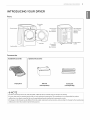 9
9
-
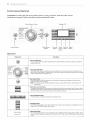 10
10
-
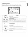 11
11
-
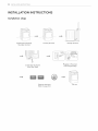 12
12
-
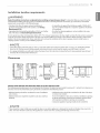 13
13
-
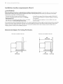 14
14
-
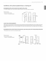 15
15
-
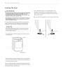 16
16
-
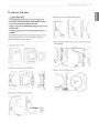 17
17
-
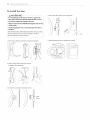 18
18
-
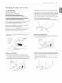 19
19
-
 20
20
-
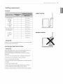 21
21
-
 22
22
-
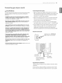 23
23
-
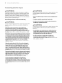 24
24
-
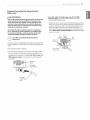 25
25
-
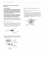 26
26
-
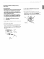 27
27
-
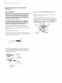 28
28
-
 29
29
-
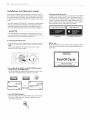 30
30
-
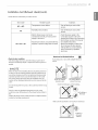 31
31
-
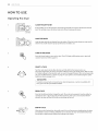 32
32
-
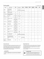 33
33
-
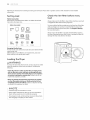 34
34
-
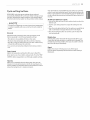 35
35
-
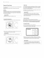 36
36
-
 37
37
-
 38
38
-
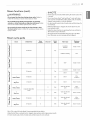 39
39
-
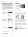 40
40
-
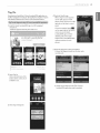 41
41
-
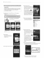 42
42
-
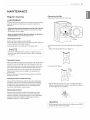 43
43
-
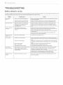 44
44
-
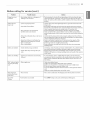 45
45
-
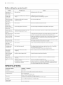 46
46
-
 47
47
-
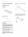 48
48
-
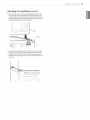 49
49
-
 50
50
-
 51
51
-
 52
52
-
 53
53
-
 54
54
-
 55
55
-
 56
56
-
 57
57
-
 58
58
-
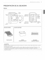 59
59
-
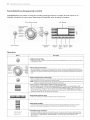 60
60
-
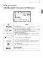 61
61
-
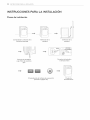 62
62
-
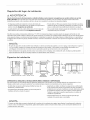 63
63
-
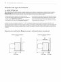 64
64
-
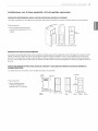 65
65
-
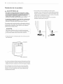 66
66
-
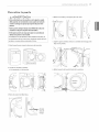 67
67
-
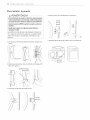 68
68
-
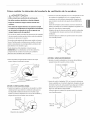 69
69
-
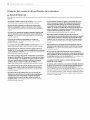 70
70
-
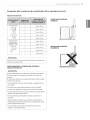 71
71
-
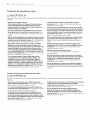 72
72
-
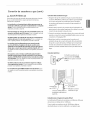 73
73
-
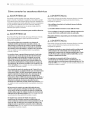 74
74
-
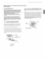 75
75
-
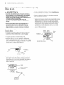 76
76
-
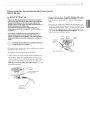 77
77
-
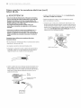 78
78
-
 79
79
-
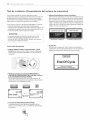 80
80
-
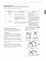 81
81
-
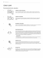 82
82
-
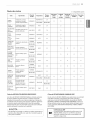 83
83
-
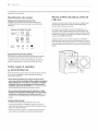 84
84
-
 85
85
-
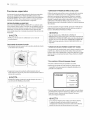 86
86
-
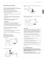 87
87
-
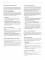 88
88
-
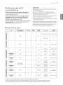 89
89
-
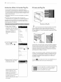 90
90
-
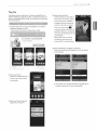 91
91
-
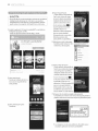 92
92
-
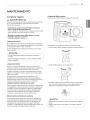 93
93
-
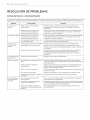 94
94
-
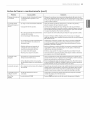 95
95
-
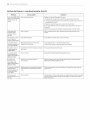 96
96
-
 97
97
-
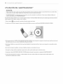 98
98
-
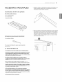 99
99
-
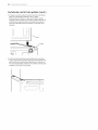 100
100
-
 101
101
-
 102
102
-
 103
103
-
 104
104
-
 105
105
-
 106
106
-
 107
107
-
 108
108


LG DLEX8500V El manual del propietario
- Categoría
- Secadoras
- Tipo
- El manual del propietario
- Este manual también es adecuado para
en otros idiomas
- English: LG DLEX8500V Owner's manual
Artículos relacionados
-
LG DLGX6002W El manual del propietario
-
LG DLG3181W/00 El manual del propietario
-
LG DLGX4271V/00 El manual del propietario
-
LG DLGX7188RM El manual del propietario
-
LG DLEX0001TM El manual del propietario
-
-
LG DLEX7700VE El manual del propietario
-
LG DLEY1701W El manual del propietario
-
LG DLEX5680V El manual del propietario