AEMC C.A 773 Manual de usuario
- Categoría
- Multimetros
- Tipo
- Manual de usuario
Este manual también es adecuado para

FRANÇAIS
ENGLISH
DEUTSCH
ITALIANO
ESPAÑOL
Notice de fonctionnement
User's manual
Bedienungsanleitung
Manuale d’uso
Manual de instrucciones
DÉTECTEUR DE TENSION
VOLTAGE DETECTOR
SPANNUNGSPRÜFER
RIVELATORE DI TENSIONE
DETECTOR DE TENSIÓN
C.A 773
C.A 773 IP2X

2
ATTENTION, risque de DANGER ! L’opérateur doit consulter la présente
notice à chaque fois que ce symbole de danger est rencontré.
Appareil protégé par une isolation double.
Matériel approprié aux travaux sous tension.
Pile.
Terre.
Le marquage CE indique la conformité aux directives européennes,
notamment DBT et CEM.
La poubelle barrée signifie que, dans l’Union Européenne, le produit
fait l’objet d’une collecte sélective conformément à la directive DEEE
2002/96/EC : ce matériel ne doit pas être traité comme un déchet ménager.
Définition des catégories de mesure :
La catégorie de mesure IV correspond aux mesurages réalisés à la source de
l’installation basse tension.
Exemple : arrivée d’énergie, compteurs et dispositifs de protection.
La catégorie de mesure III correspond aux mesurages réalisés dans l’installation
du bâtiment.
Exemple : tableau de distribution, disjoncteurs, machines ou appareils indus-
triels fixes.
La catégorie de mesure II correspond aux mesurages réalisés sur les circuits
directement branchés à l’installation basse tension.
Exemple : alimentation d’appareils électrodomestiques et d’outillage portable.
English ........................................................................... 22
Deutsch ......................................................................... 42
Italiano ........................................................................... 62
Español ......................................................................... 82
Vous venez d’acquérir un détecteur de tension C.A 773 ou C.A 773 IP2X et nous
vous remercions de votre confiance.
Pour obtenir le meilleur service de votre appareil :
lisez attentivement cette notice de fonctionnement,
respectez les précautions d’emploi.

3
PRÉCAUTIONS D’EMPLOI
Cet appareil est protégé contre des tensions n’excédant pas 1000 V par rapport à la
terre en catégorie de mesure IV.
La protection assurée par l’appareil peut-être compromise si celui-ci est utilisé
de façon non spécifiée par le constructeur et mettre ainsi l’utilisateur en danger.
Respectez la tension et l’intensité maximales assignées et la catégorie de mesure.
N’utilisez pas votre appareil sur des réseaux dont la tension ou la catégorie sont
supérieures à celles mentionnées.
Respectez les conditions d’utilisation, à savoir la température, l’humidité, l’altitude,
le degré de pollution et le lieu d’utilisation.
Lors de la manipulation des pointes de touche, ne placez pas vos doigts au-delà
de la garde physique.
Utilisez des accessoires de branchement dont la catégorie de mesure et la tension
de service sont supérieures ou égales à celles de l’appareil.
N’utilisez pas l’appareil s’il est ouvert, détérioré ou mal remonté, ou ses accessoires
s’ils paraissent endommagés.
L’appareil doit rester propre afin de pouvoir vérifier le bon état des isolants des
cordons, boîtier et accessoires. Tout élément dont l’isolant est détérioré (même
partiellement) doit être consigné pour réparation ou pour mise au rebut.
L’appareil est conçu pour être utilisé par du personnel qualifié et en accord avec
les règles de sécurité nationales.
Il est conseillé d’utiliser des protections individuelles de sécurité dès que les
situations environnementales d’emploi de l’appareil l’exigent.
Toute procédure de dépannage ou de vérification métrologique doit être effectuée
par du personnel compétent et agréé.
SOMMAIRE
1. Présentation ..................................................................................................... 4
2. Utilisation ......................................................................................................... 7
3. Caractéristiques ............................................................................................ 15
4. Maintenance .................................................................................................. 18
5. Garantie ......................................................................................................... 19
6. Pour commander ........................................................................................... 20

4
SAFETY TESTER
1
0
0
0
V
C
A
T
.
I
V
ELV
Ph
AC
DC
V
400
230
127
50
690
1000
1400
12
24
+
C.A 773
DC
L1
AUTO
TEST
30mA
30mA
L3
L1
L2
Ω
V
kΩ
DC
AC
1. PRÉSENTATION
1.1. C.A 773
Pointe de
touche rouge.
Pointe de
touche
noire L1.
Capuchon.
Boutons de
fonction.
Indicateur
de polarité.
Afficheur
numérique
rétroéclairé.
Bargraphe.
Indicateur de
phase.
Indicateur
de tension
dangereuse.
Éclairage
du point de
mesure.

5
1.2. AU DOS
La pointe de touche noire peut se fixer au dos de l’appareil de deux manières
possible :
à plat, et l’entraxe des pointes de touche est de 16 mm,
sur le côté, et l’entraxe des pointes de touche est de 19 mm.
Pointe de touche
rouge (dessous).
Pointe de touche
noire.
Trappe à pile.
16 mm 19 mm
Gardes.

6
1.3. POINTES DE TOUCHE
Les bouts des pointes de touche peuvent se retirer.
1.4. C.A 773 IP2X
Voir le § 2.8.
1.4. FONCTIONNALITÉS
Le C.A 773 est un Détecteur De Tension (DDT) à voyants.
Il est conforme aux prescriptions de la norme IEC 61243-3.
La fonction principale du C.A 773 est la Vérification d’Absence de Tension (VAT).
Il détecte les tensions dangereuses, c’est à dire supérieure à la TBT (très basse
tension : 50 Vac ou 120 Vdc), même si les piles de l’appareil sont usées ou absentes.
Ses autres fonctions sont :
Indication d’une tension comprise entre 12 et 1000 Vac ou 1400 Vdc avec indication
de la polarité.
Indication de la qualité du niveau de continuité.
Indication de la position de la phase.
Indication de l’ordre des phases.
Commutation de charge (contrôle du déclenchement des différentiels 30 mA).
Les tensions indiquées sur le C.A 773 sont des tensions nominales. Assurez-vous
qu’il sera utilisé sur des réseaux de tensions normalisées.
SAFETY TESTER
1
0
0
0
V
C
A
T
.
I
V
ELV
Ph
AC
DC
V
400
230
127
50
690
1000
1400
12
24
+
C.A 773
DC
L1
AUTO
TEST
30mA
30mA
L3
L1
L2

7
2. UTILISATION
Cet appareil est un détecteur. Les indications qu’il fournit ne doivent pas être utili-
sées à des fins de mesure.
2.1. AUTO TEST
Avant d’utiliser le C.A 773, procédez à un autotest. Il permet de vérifier l’intégrité
du cordon et des pointes de touche, le bon fonctionnement du circuit électronique
et un niveau de tension suffisant pour les piles.
Connectez la pointe de touche rouge sur la borne + et la pointe de touche noire
sur la borne L1.
Amenez les 2 pointes de touche en contact et appuyez sur le bouton AUTO TEST.
Maintenez l’appui autant que nécessaire.
Si tous les voyants de l’appareil sauf ELV s’allument, que le signal sonore retentit,
et que l’afficheur numérique indique «ready» (prêt) alors l’appareil fonctionne
correctement et peut être utilisé.
SAFETY TESTER
1
0
0
0
V
C
A
T
.
I
V
C.A 773
ELV
Ph
AC
DC
V
400
230
127
50
690
1000
1400
12
24
+
DC
L1
AUTO
TEST
30mA
30mA
L3
L1
L2
Ω
+
ELV
Ph
AC
DC
V
400
230
127
50
690
1000
1400
12
24
+
DC
Si un voyant sur deux s’allume ainsi que le symbole , c’est qu’il faut remplacer les
piles (voir § 4.2).
+
ELV
Ph
AC
DC
V
400
230
127
50
690
1000
1400
12
24
+
DC

8
Si un voyant sur trois s’éteint et que l’afficheur indique «bad» (mauvais), c’est
qu’il y a un problème au niveau des cordons. Vérifiez qu’elles sont correctement
branchées et qu’elles sont bien en contact et appuyez à nouveau sur le bouton
AUTO TEST. Si le problème persiste encore, l’appareil ne doit plus être utilisé.
Si aucun voyant n’est allumé, remplacez les piles (voir § 4.2). Si le problème
persiste avec des piles neuves, l’appareil est défectueux et doit être envoyé en
réparation (voir § 4.4).
Après chaque mesure, refaites un autotest afin de valider le bon fonctionnement
de l’appareil.
Dans une atmosphère bruyante, assurez-vous de bien entendre le signal sonore
émis par l’appareil.
Remarque : Si le bouton AUTO TEST est maintenu appuyé plus de 10 secondes
alors que les pointes de touche ne sont pas en contact, l’appareil se
met en veille.
2.2. ÉCLAIRAGE DU POINT DE MESURE
Le C.A 773 permet d’éclairer le point de mesure grâce à un voyant blanc situé sous
la pointe de touche rouge.
Pour allumez la lumière, appuyez sur le bouton
Ω
.
SAFETY TESTER
1
0
0
0
V
C
A
T
.
I
V
C.A 773
ELV
Ph
AC
DC
V
400
230
127
50
690
1000
1400
12
24
+
DC
AUTO
TEST
30mA
L3
L1
L2
Ω
+
ELV
Ph
AC
DC
V
400
230
127
50
690
1000
1400
12
24
+
DC
Pour éteindre la lumière, appuyez à nouveau sur le bouton
Ω
ou attendez qu’elle
s’éteigne automatiquement au bout de 10 secondes environ.

9
2.3. DÉTECTION DE TENSION
Connectez la pointe de touche rouge sur la borne +et la pointe de touche noire
sur la borne L1.
Placez vos mains derrière la garde de l’appareil et de la pointe de touche.
Position limite des mains.
Placez les pointes de touche sur l’élément à tester et maintenez fermement le
contact.
Il n’est pas nécessaire d’allumer le C.A 773 car il se met en fonctionnement auto-
matiquement. La tension s’affiche sur le bargraphe et sur l’afficheur numérique.
Si la tension présente est :
alternative : les voyants s’allument pour indiquer sa valeur et les voyants + (vert)
et - (orange) sont allumés.
SAFETY TESTER
1
0
0
0
V
C
A
T
.
I
V
C.A 773
ELV
Ph
AC
DC
V
400
230
127
50
690
1000
1400
12
24
+
DC
L1
AUTO
TEST
30mA
L3
L1
L2
30mA
Ω
ELV
Ph
AC
DC
V
400
230
127
50
690
1000
1400
12
24
+
DC
V
AC
continue : les voyants s’allument pour indiquer sa valeur et le voyant + (vert) ou
le voyant - (orange) s‘allume pour indiquer la polarité.
ELV
Ph
AC
DC
V
400
230
127
50
690
1000
1400
12
24
+
DC
V
DC
dangereuse (> 50 Vac ou 120 Vdc) : le voyant ELV (rouge) clignote d’autant plus
rapidement que la tension présente est élevée et l’appareil émet des bips sonores.
ELV : Extra Low Voltage ou Très Basse Tension de Sécurité (TBT). Ce voyant redondant
indique que la tension est supérieure à la TBT.

10
Les deux premiers voyants du bargraphe sont verts pour indiquer que la tension
n’est pas dangereuse et l’appareil n’émet pas de bip. Les suivants sont rouges
et l’appareil émet des bips.
Si la tension dépasse 1000 Vac ou 1400 Vdc, l’afficheur numérique indique «over-
load» (dépassement de gamme). Le bargraphe et le signal sonore restent actifs.
ELV
Ph
AC
DC
V
400
230
127
50
690
1000
1400
12
24
+
DC
ELV
Ph
AC
DC
V
400
230
127
50
690
1000
1400
12
24
+
DC
SAFETY TESTER
1
0
0
0
V
C
A
T
.
I
V
C.A 773
ELV
Ph
AC
DC
V
400
230
127
50
690
1000
1400
12
24
+
DC
L1
Ω
AUTO
TEST
30mA
L3
L1
L2
30mA
Ω
R
2.4. INDICATION DE LA QUALITÉ DU NIVEAU DE CONTINUITÉ
Comme pour la détection de tension, connectez la pointe de touche rouge sur la
borne + et la pointe de touche noire sur la borne L1.
Placez vos mains derrière la garde de l’appareil et de la pointe de touche.
Placez les pointes de touche sur l’élément à tester et maintenez fermement le
contact.
Si le voyant ELV s’allume seul, les piles sont usées ou absentes.
Si l’appareil n’a pas été utilisé depuis plus de 10 minutes ou s’il a été placé en veille,
effectuez d’abord un autotest afin de le placer en veille active.
Maintenez le bouton
Ω
appuyé.
Si aucune tension n’est détectée, le C.A 773 effectue une mesure de continuité.
Le résultat n’est indiqué que sur l’afficheur numérique.

11
S’il est inférieur à 125 W, l’appareil émet un signal sonore continu.
2.5. DÉTECTION DE PHASE
Le C.A 773 effectue une détection de phase unipolaire. C’est à dire qu’il suffit de
brancher une seule pointe de touche pour savoir si une phase est présente.
Pour fonctionner correctement, la détection de phase doit être utilisée sur des
réseaux référencés à la terre.
Elle permet, par exemple, de savoir où se trouve la phase sur une prise pour un
réseau référencé à la terre.
Connectez la pointe de touche rouge sur la borne L1.
Placez vos mains derrière la garde de l’appareil.
Placez la pointe de touche sur l’élément à tester et maintenez fermement le contact.
SAFETY TESTER
1
0
0
0
V
C
A
T
.
I
V
C.A 773
+
ELV
Ph
AC
DC
V
400
230
127
50
690
1000
1400
12
24
+
DC
AUTO
TEST
30mA
L3
L1
L2
30mA
Ω
Si la pointe de touche est bien sur la phase, le voyant Ph (phase) clignote l’appareil
émet des bips sonores.
ELV
Ph
AC
DC
V
400
230
127
50
690
1000
1400
12
24
+
DC
Attention : ce n’est pas parce que le voyant Ph ne clignote pas qu’il n’y a pas de
tension dangereuse sur la prise.
2.6. ORDRE DES PHASES
Placez la pointe de touche noire sur la première phase du système triphasé et la
pointe de touche rouge sur la deuxième phase. L’appareil indique la tension présente.
Appuyez sur le bouton .

12
SAFETY TESTER
1
0
0
0
V
C
A
T
.
I
V
C.A 771
ELV
Ph
AC
DC
V
400
230
127
50
690
1000
1400
12
24
+
DC
L1
AUTO
TEST
30mA
L3
L1
L2
30mA
Ω
L3
PE
N
L1
L2
Lorsque la référence est acquise, le C.A 773 émet deux bips aigus, et «reference»
s’affiche en fixe.
Déplacez alors la pointe de touche rouge sur la dernière phase du système.
Si la tension est inférieure à 50 Vac ou continue, la mesure n’est pas possible.
Sinon, l’appareil indique qu’il prend la référence de tension en faisant clignoter
«référence» sur l’afficheur.
S’il y a un problème, c’est à dire si l’appareil ne détecte pas de changement de
phase dans les 10 secondes ou si les phases ne sont pas équilibrées, il signale une
erreur en émettant deux bips graves et en affichant «erreur».
SAFETY TESTER
1
0
0
0
V
C
A
T
.
I
V
C.A 773
ELV
Ph
AC
DC
V
400
230
127
50
690
1000
1400
12
24
+L1
AUTO
TEST
30mA
L3
L1
L2
30mA
Ω
L3
PE
N
L1
L2
L’appareil indique qu’il fait la mesure en affichant «measurement».
Sinon, l’appareil indique le sens de rotation des phases :
L123 et en émettant un bip grave suivi d’un bip aigu,
ou L132 et en émettant un bip aigu suivi d’un bip grave.

13
2.7. COMMUTATION DES CHARGES
Dans la détection de tension, s’il y a une tension perturbatrice à proximité de
l’élément testé, l’appareil peut indiquer la présence d’une tension de service alors
qu’il n’y en a pas.
Si cette tension est < 400 V, l’appui sur les deux touches
30mA
permet de distinguer
une tension perturbatrice d’une tension de service. S’il s’agit d’une tension pertur-
batrice, l’indication de tension disparaît pendant l’appui.
Sur des systèmes équipés de disjoncteurs différentiels 30 mA, il est possible de les
déclencher en utilisant ce double appui.
Placez la pointe de touche + sur la phase et la pointe de touche noire sur le
conducteur de protection, ces deux conducteurs appartenant au circuit protégé
par le différentiel à tester.
Une indication de tension apparaît sur le bargraphe et sur l’afficheur numérique.
Appuyez sur les deux touches
30mA
, celle de l’appareil et celle de la pointe de touche.
SAFETY TESTER
1
0
0
0
V
C
A
T
.
I
V
C.A 773
ELV
Ph
AC
DC
V
400
230
127
50
690
1000
1400
12
24
+
DC
L1
AUTO
TEST
30mA
L3
L1
L2
30mA
Ω
L
N
PE
30 mA
Si la tension mesurée est comprise entre 8 Veff et 400 Veff, le test est déclenché.
Si la tension est de 230 Veff, le différentiel 30 mA déclenche et l’indication de tension
disparaît du bargraphe et de l’afficheur numérique.
Ce test génère un courant important qui fait chauffer l’appareil. Lorsqu’il est trop
chaud, il faut attendre qu’il refroidisse pour pouvoir continuer à utiliser cette fonction.
2.8. POINTES DE TOUCHE IP2X
Les cordons à pointe de touche IP2X sont livrés avec l’appareil (C.A 773 IP2X) ou
en option (C.A 773) selon le modèle commandé.
L’utilisation d’accessoires IP2X est un élément complémentaire de sécurité. Ces
accessoires peuvent être obligatoires dans certains pays.
En France, les normes (NF C 18-510, UTE C 18-510) et les décrets gouvernementaux
en imposent l’usage.
Connectez la pointe de touche rouge IP2X sur la borne + et la pointe de touche
noire IP2X sur la borne L1.

14
SAFETY TESTER
1
0
0
0
V
C
A
T
.
I
V
ELV
Ph
AC
DC
V
400
230
127
50
690
1000
1400
12
24
+
C.A 773
DC
L1
50
12
24
AUTO
TEST
30mA
30mA
L3
L1
L2
Ω
Pointes de
touche IP2X
Pour effectuer un test, placez la pointe sur l’objet à
tester et appuyez pour faire coulisser la protection.

15
3. CARACTÉRISTIQUES
3.1. CONDITIONS DE RÉFÉRENCE
Grandeur d’influence Valeurs de référence
Température 23 ± 5 °C
Humidité relative 45 à 75 % HR
Tension d’alimentation 3 ± 0,1 V
Fréquence du signal mesuré DC ou 45 à 65 Hz
Type de signal sinusoïdal
Champ électrique extérieur < 1 V/m
Champ magnétique DC extérieur < 40 A/m
3.2. CARACTÉRISTIQUES ÉLECTRIQUES
3.2.1. TENSION
Tensions nominales : 12, 24, 50, 127, 230, 400, 690, 1000 Vac/ Vdc et 1400 Vdc.
Incertitude intrinsèque : ± (3% + 5 pt)
Résolution : 0,1 V de 1 à 299,9 V
1 V à partir de 300 V
Fréquence de fonctionnement : DC et 16,67 à 800 Hz.
Intensité d’entrée maximale : 3,5 mArms.
Impédance d’entrée > 500 kW.
Temps de réponse < 500 ms.
Temps de réponse du voyant ELV < 1 s.
La LED correspondant à la tension V s’allume avant que la tension atteigne 85%V.
Si la tension présente est < 12 V, aucun voyant n’est allumé.
Si la tension présente est < 1 V, l’affichage numérique est éteint.
Le C.A 773 doit être utilisé uniquement sur des réseaux de tensions normalisées.
Cycle de fonctionnement : 30 s (durée maximale pendant laquelle l’appareil peut
être connecté à un élément sous tension) - 240 s (temps de repos minimal pendant
lequel le détecteur ne doit pas être connecté à un élément sous tension).
3.2.2. CONTINUITÉ
La détection de continuité est inhibée si une tension > 1 V est présente.
Domaine de mesure : 0 à 3 kW
Incertitude intrinsèque : ± (3% + 5 pt)
Résolution : 0,1 W de 1 à 299,9 W
0,001 kW de 0,3 à 3 kW
Seuil de déclenchement du signal sonore :100 W -0% +50%
Courant de test ≤ 1 mA
Tension en circuit ouvert ≤ 5 V
3.2.3. REPÉRAGE DE PHASE
15 Hz < fréquence < 65 Hz
50 Vac < tension < 1000 Vac pour 45 Hz < fréquence ≤ 65 Hz
150 Vac < tension < 1000 Vac pour fréquence < 45 Hz

16
3.2.4. ORDRE DES PHASES
Fréquence comprise entre 45 et 400 Hz.
Tension comprise entre 50 et 1000 Vac entre phases.
Temps d’acquisition des informations après contact ≤ 1 s.
Temps de rétention de l’information : 10 s.
Taux de déséquilibre admissible en amplitude : 20%.
Taux d’harmoniques admissible en tension : 10%.
Réjection des trames de télécommande EDF (TCC-175 Hz-188 Hz).
3.2.5. COMMUTATION DE CHARGE
Charge commutée : environ 8 kW.
Courant crête : 90 mA.
Courant consommé à 230 Vac : 30 mA.
Déclenchement entre 8 et 400 Vac.
Protection contre les surcharges au bout de 10 secondes à 230 V et 2 secondes
à 400 V.
3.3. CONDITIONS D’ENVIRONNEMENT
L’appareil est de type N. Il doit être utilisé dans les conditions suivantes :
100
90
80
70
60
50
40
30
20
10
0
-50 -40 -30 -20 -10 0 10 20 30 40 50 60 70 80 90
°C
321
%HR
1 : Domaine de référence
2 : Domaine de fonctionnement
-15 à +45°C et 20 à 95 % HR hors condensation.
3 : Domaine de stockage (sans pile)
-40 à +70°C et 20 à 95 % HR hors condensation.
En cas de non utilisation prolongée ou de stockage, retirer les piles du boîtier.
Utilisation en intérieur et en extérieur sans pluie.
Degré de pollution : 2.
Altitude : < 2000 m.

17
3.4. ALIMENTATION
L’alimentation du C.A 773 est réalisée par deux piles 1,5 V alcaline (type AA ou LR6).
L’autonomie est de 2 500 mesures de 10 secondes.
Les piles peuvent être remplacées par des accumulateurs rechargeables, mais
l’autonomie sera bien moindre.
3.5. CARACTÉRISTIQUES CONSTRUCTIVES
Dimensions (L x l x P)
de l’appareil 228 x 60 x 39 mm
de la pointe de touche 218 x 35 x 25 mm
Masse 350 g environ
Cordon longueur 1 m
Indice de protection
IP 65 selon IEC 60529
IK 06 - 1J - Méthode Eha marteau pendulaire selon IEC 50102
Chute 2 mètres.
3.6. CONFORMITÉ AUX NORMES INTERNATIONALES
Détecteur de tension bipolaire EN 61243-3 Ed. 2 de 2010.
Conforme aux prescriptions de la NFC 18-510.
L’appareil est conforme selon l’IEC 61010-1, 1000V CAT IV.
3.7. COMPATIBILITÉ ÉLECTROMAGNÉTIQUE
Émission et immunité en milieu industriel selon IEC 61326-1.

18
4. MAINTENANCE
Excepté les piles, l’appareil ne comporte aucune pièce susceptible d’être
remplacée par un personnel non formé et non agréé. Toute intervention non
agréée ou tout remplacement de pièce par des équivalences risque de com-
promettre gravement la sécurité.
4.1. NETTOYAGE
L’appareil doit être maintenu en parfait état de propreté.
Pour procéder au nettoyage, déconnectez tout branchement de l’appareil.
Utilisez un chiffon doux, légèrement imbibé d’eau savonneuse. Rincez avec un
chiffon humide et séchez rapidement avec un chiffon sec ou de l’air pulsé. N’utilisez
pas d’alcool, de solvant ou d’hydrocarbure.
4.2. REMPLACEMENT DES PILES
Toute manipulation de la trappe à piles doit se faire sur un appareil propre et dans
un environnement propre.
Si, lors de l’auto test, le symbole s’affiche, vous devez remplacer les piles.
Déconnectez tout branchement de l’appareil.
A l’aide d’un tournevis, dévissez les deux vis imperdables de la trappe à pile située
sous l’appareil.
Retirez les piles usagées et remplacez-les par deux piles neuve (piles 1,5 V alcaline
de type AA ou LR6).
Refermez la trappe à pile et assurez-vous de sa fermeture complète et correcte.
Revissez les deux vis.
Les piles et les accumulateurs usagés ne doivent pas être traités comme
des déchets ménagers. Rapportez-les au point de collecte approprié
pour le recyclage.
4.3. VÉRIFICATION MÉTROLOGIQUE
Comme tous les appareils de mesure ou d’essais, une vérification pério-
dique est nécessaire.
Nous vous conseillons une vérification annuelle de cet appareil. Pour les vérifications
et étalonnages, adressez-vous à nos laboratoires de métrologie accrédités COFRAC
ou aux centres techniques MANUMESURE.
4.4. RÉPARATION
Pour les réparations sous garantie et hors garantie, contactez votre agence commer-
ciale Chauvin Arnoux la plus proche ou votre centre technique régional Manumesure
qui établira un dossier de retour et vous communiquera la procédure à suivre.

19
Pour les réparations hors de France métropolitaine, sous garantie et hors garantie,
retournez l’appareil à votre agence Chauvin Arnoux locale ou à votre distributeur.
5. GARANTIE
Notre garantie s’exerce, sauf stipulation expresse, pendant douze mois après la
date de mise à disposition du matériel. L’extrait de nos Conditions Générales de
Vente sera communiqué sur demande.
La garantie ne s’applique pas suite à :
une utilisation inappropriée de l'équipement ou à une utilisation avec un matériel
incompatible ;
des modifications apportées à l'équipement sans l'autorisation explicite du service
technique du fabricant ;
des travaux effectués sur l'appareil par une personne non agréée par le fabricant ;
une adaptation à une application particulière, non prévue par la définition du matériel
ou non indiquée dans la notice de fonctionnement ;
des dommages dus à des chocs, chutes ou inondations.

20
6. POUR COMMANDER
Détecteur de tension C.A 773 ..........................................................P01191773
Livré avec :
une pointe de touche rouge Ø 2 mm,
une pointe de touche noire Ø 2 mm,
un capuchon de protection pour les pointes de touche,
une attache velcro,
deux piles alcaline AA ou LR6,
une notice de fonctionnement 5 langues,
un certificat de vérification.
Détecteur de tension C.A 773 IP2X .................................................P01191773A
Livré avec :
une pointe de touche rouge IP2X Ø 4 mm,
une pointe de touche noire IP2X Ø 4 mm,
une attache velcro,
deux piles alcaline AA ou LR6,
une notice de fonctionnement 5 langues,
un certificat de vérification.
6.1. ACCESSOIRES ET RECHANGE
Pointes de touche Ø 2 x 4 mm (une rouge et une noire) .................... P0112123Z
CAT IV CAT IV
Pointes de touche Ø 2 x 15 mm (une rouge et une noire) .................. P01102124Z
Pointes de touche Ø 4 x 15 mm (une rouge et une noire) .................. P01102125Z

21
Pointe de touche rouge IP2X Ø 2 mm (une rouge et une noire) .......... P01102127Z
Pointes de touche rouge IP2X Ø 4 mm (une rouge et une noire) ........ P01102128Z
Capuchon ........................................................................................... P01102126Z
6.2. OPTIONS
Sacoche de transport .......................................................................... P01298076

22
WARNING, risk of DANGER! The operator must refer to these instruc-
tions whenever this danger symbol appears.
Equipment protected by double insulation.
Equipment suitable for live work.
Battery.
Earth.
The CE marking indicates conformity with European directives, in
particular LVD and EMC.
The rubbish bin with a line through it indicates that, in the European Union,
the product must undergo selective disposal in compliance with Directive
WEEE 2002/96/EC. This equipment must not be treated as household
waste.
Definition of measurement categories:
Measurement category IV corresponds to measurements taken at the source of
low-voltage installations.
Example: power feeders, counters and protection devices.
Measurement category III corresponds to measurements on building installations.
Example: distribution panel, circuit-breakers, machines or fixed industrial devices.
Measurement category II corresponds to measurements taken on circuits directly
connected to low-voltage installations.
Example: power supply to domestic electrical appliances and portable tools.
Thank you for purchasing a C.A 773 or C.A 773 IP2X voltage detector.
For best results from your instrument:
read these operating instructions carefully,
comply with the precautions for use.
ENGLISH

23
PRECAUTIONS FOR USE
This device is protected against voltages up to 1000V with respect to earth in meas-
urement category IV.
The protection provided by the device may be compromised if it is used other than
as specified by the manufacturer and so endanger the user.
Do not exceed the maximum rated voltage and current and the measurement
category. Do not use your instrument on networks of which the voltage or category
exceeds those stated.
Comply with the conditions of use, namely the temperature, the humidity, the
altitude, the degree of pollution, and the place of use.
When handling the test probes, keep your fingers behind the physical guard.
Use connection accessories of which the measurement category and service volt-
age are at least equal to those of the device.
Do not use the device if it is open, damaged, or poorly reassembled, or its acces-
sories if they seem to be damaged.
The device must be kept clean so that the condition of the cable insulators, housing,
and accessories can be checked. Any component whose insulator is damaged
(even partially) must be sent for repair or scrapped.
The device is designed to be used by qualified personnel and in compliance with
national safety rules.
We recommend wearing personal protective equipment when the environment in
which the device is used makes it necessary.
All troubleshooting and metrological checks must be done by competent, ac-
credited personnel.
CONTENTS
1. Introduction .................................................................................................... 24
2. Use .................................................................................................................. 27
3. Characteristics .............................................................................................. 35
4. Maintenance .................................................................................................. 38
5. Warranty ........................................................................................................ 39
6. To order .......................................................................................................... 40

24
SAFETY TESTER
1
0
0
0
V
C
A
T
.
I
V
ELV
Ph
AC
DC
V
400
230
127
50
690
1000
1400
12
24
+
C.A 773
DC
L1
AUTO
TEST
30mA
30mA
L3
L1
L2
Ω
V
k
Ω
DC
AC
1. INTRODUCTION
1.1. C.A 773
Red test
probe.
Black test
probe L1.
Cap.
Function
buttons.
Polarity
indicator.
Backlit digi-
tal display.
Bargraph.
Phase indicator.
Hazardous volt-
age indicator.
Lighting of
measure-
ment point.

25
1.2. ON THE BACK
There are two ways to attach the black test probe to the back:
flat, with a 16 mm distance between test probes,
on the side, with a 19 mm distance between test probes.
Red test probe
(underneath).
Black test probe.
Battery compart-
ment cover.
16 mm 19 mm
Guards.

26
1.3. TEST PROBES
The tips of the test probes are removable.
1.4. C.A 773 IP2X
See § 2.8.
1.5. FUNCTIONALITY
The C.A 773 is a voltage detector with indicator lights.
It complies with the recommendations of the IEC 61243-3 standard.
The main function of the C.A 773 is Voltage Absence Testing (VAT). It detects haz-
ardous voltages, i.e. higher than ELV (extra-low voltage) 50 Vac or 120 Vdc), even if
the device’s batteries are spent or absent.
Its other functions are:
Indicating a voltage between 12 and 1000 Vac or 1400 Vdc with polarity indication.
Indicating the quality of the continuity level.
Indicating the phase position.
Indicating the phase order.
Load switching (controlling the triggering of the 30 mA differential circuit breakers).
The voltages indicated on the C.A 773 are nominal voltages. Ensure that it is used
on voltage-normalized networks.
SAFETY TESTER
1
0
0
0
V
C
A
T
.
I
V
ELV
Ph
AC
DC
V
400
230
127
50
690
1000
1400
12
24
+
C.A 773
DC
L1
AUTO
TEST
30mA
30mA
L3
L1
L2

27
2. USE
This device is a detector. The indications it provides must not be used for measure-
ment purposes.
2.1. SELF-TEST
Before using the C.A 773, run a self-test. This checks the integrity of the cable and
the test probes, correct operation of the electronic circuit, and a sufficient voltage
level for the batteries.
Connect the red test probe to the + terminal and the black test probe to the L1
terminal.
Bring the two test probes into contact and press the AUTO TEST button. Hold it
down as long as necessary.
If all indicators on the device except ELV light up, the buzzer sounds and the
digital display indicates “ready”, the device is operating properly and is usable.
+
ELV
Ph
AC
DC
V
400
230
127
50
690
1000
1400
12
24
+
DC
If every second indicator lights up along with the symbol, the batteries must be
replaced (see § 4.2).
+
ELV
Ph
AC
DC
V
400
230
127
50
690
1000
1400
12
24
+
DC
SAFETY TESTER
1
0
0
0
V
C
A
T
.
I
V
C.A 773
ELV
Ph
AC
DC
V
400
230
127
50
690
1000
1400
12
24
+
DC
L1
AUTO
TEST
30mA
30mA
L3
L1
L2
Ω

28
If every third indicator lights up and the display indicates “bad”, there is a problem
with the test probes. Check that they are connected correctly and are in contact, and
then press the AUTO TEST button again. If the problem persists, the test probes
must be replaced. If the problem still persists, the device must no longer be used.
If no indicators light up, replace the batteries (see § 4.2). If the problem persists
with new batteries, the device is defective and must be sent for repair (see § 4.4).
Repeat the self-test after each measurement to confirm that the device is operat-
ing properly.
In a noisy atmosphere, ensure that you are able to hear the buzzer.
Note: If the AUTO TEST button is held down for more than 10 seconds with the test
probes not in contact, the device goes into stand-by mode.
2.2. LIGHTING OF MEASUREMENT POINT
The C.A 773 can light up the measurement point, with a white indicator light located
under the red test probe.
To switch this light on, press the
Ω
button.
SAFETY TESTER
1
0
0
0
V
C
A
T
.
I
V
C.A 773
ELV
Ph
AC
DC
V
400
230
127
50
690
1000
1400
12
24
+
DC
AUTO
TEST
30mA
L3
L1
L2
Ω
+
ELV
Ph
AC
DC
V
400
230
127
50
690
1000
1400
12
24
+
DC
To switch the light off, press the
Ω
button again, or wait for it to extinguish itself
automatically after about 10 seconds.

29
Hand position limit.
Place the test probes on the element to be tested, and hold them firmly in contact.
There is no need to switch on the C.A 773; it starts up automatically. The voltage is
displayed on the bargraph and on the digital display unit.
If the voltage present is:
AC: the indicators light up to indicate its value, and the + (green) and - (orange)
indicators are lit.
SAFETY TESTER
1
0
0
0
V
C
A
T
.
I
V
C.A 773
ELV
Ph
AC
DC
V
400
230
127
50
690
1000
1400
12
24
+
DC
L1
AUTO
TEST
30mA
L3
L1
L2
30mA
Ω
ELV
Ph
AC
DC
V
400
230
127
50
690
1000
1400
12
24
+
DC
V
AC
DC: the indicators light up to indicate its value, and the + (green) indicator or the
- (orange) indicator lights up to indicate the polarity.
ELV
Ph
AC
DC
V
400
230
127
50
690
1000
1400
12
24
+
DC
V
DC
hazardous (> 50 Vac or 120 Vdc): the ELV (red) indicator flashes (the faster the
flashing, the higher the voltage), and the device beeps.
ELV: Extra Low Voltage. This redundant indicator light indicates that the voltage
is above ELV.
2.3. VOLTAGE DETECTION
Connect the red test probe to the + terminal and the black test probe to the L1
terminal.
Place your hands behind the guards on the device and the test probe.

30
The first two indicators on the bargraph are green to indicate that the voltage is
not hazardous, and the device does not beep. The next ones are red, and the
device beeps.
If the voltage exceeds 1000 Vac or 1400 Vdc, the digital display indicates “over-
load”. The bargraph and the audible signal remain active.
2.4. INDICATING THE QUALITY OF THE CONTINUITY LEVEL.
As for voltage detection, connect the red test probe to the + terminal and the black
test probe to the L1 terminal.
Place your hands behind the guards on the device and the test probe.
Place the test probes on the element to be tested, and hold them firmly in contact.
ELV
Ph
AC
DC
V
400
230
127
50
690
1000
1400
12
24
+
DC
ELV
Ph
AC
DC
V
400
230
127
50
690
1000
1400
12
24
+
DC
SAFETY TESTER
1
0
0
0
V
C
A
T
.
I
V
C.A 773
ELV
Ph
AC
DC
V
400
230
127
50
690
1000
1400
12
24
+
DC
L1
Ω
AUTO
TEST
30mA
L3
L1
L2
30mA
Ω
R
If only the ELV indicator lights up, the batteries are spent or absent.
If the device has been idle for more than 10 minutes or if it was set to stand-by
mode, run a self-test first, to place it in active stand-by.
Keep the
Ω
button pressed.
If no voltage is detected, the C.A 773 performs a continuity check.
The result is indicated only on the digital display.
If it is less than 125 W, the device emits a continuous audible signal.

31
2.5. PHASE DETECTION
The C.A 773 performs single-pole phase detection.. This means that you can con-
nect just one test probe to find out if a phase is present.
To operate properly, phase detection must be used on earth-referenced networks.
This means, for example, that you can locate the phase on a connector for an
earth-referenced network.
Connect the black test probe to terminal L1.
Place your hands behind the guard on the device.
Place the test probe on the element to be tested, and hold it firmly in contact.
If the test probe is on the phase, the Ph (phase) indicator flashes and the device
beeps.
SAFETY TESTER
1
0
0
0
V
C
A
T
.
I
V
C.A 773
+
ELV
Ph
AC
DC
V
400
230
127
50
690
1000
1400
12
24
+
DC
AUTO
TEST
30mA
L3
L1
L2
30mA
Ω
ELV
Ph
AC
DC
V
400
230
127
50
690
1000
1400
12
24
+
DC
Note: The fact that the Ph indicator is not flashing does not mean that there is not
a hazardous voltage on the connector.
2.6. ORDER OF PHASES
Place the black test probe on the first phase of the three-phase system and the red
test probe on the second phase. The device indicates the voltage that is present.
Press the button.

32
When the reference has been acquired, the C.A 773 emits two treble beeps and
“reference” is displayed steadily.
Then shift the red probe tip to the last phase of the system.
SAFETY TESTER
1
0
0
0
V
C
A
T
.
I
V
C.A 771
ELV
Ph
AC
DC
V
400
230
127
50
690
1000
1400
12
24
+
DC
L1
AUTO
TEST
30mA
L3
L1
L2
30mA
Ω
L3
PE
N
L1
L2
SAFETY TESTER
1
0
0
0
V
C
A
T
.
I
V
C.A 773
ELV
Ph
AC
DC
V
400
230
127
50
690
1000
1400
12
24
+L1
AUTO
TEST
30mA
L3
L1
L2
30mA
Ω
L3
PE
N
L1
L2
If the voltage is less than 50 Vac or DC, it cannot be measured.
Otherwise, the device reports that it is taking the voltage reference by the blinking
of “reference” on the display unit.
The device displays “measurement” to indicate that it is making the measurement.
If there is a problem, i.e. if the device does not detect a phase change within 10
seconds or if the phases are not balanced, it indicates an error by emitting two
low-pitched beeps and displaying “error”.
Otherwise, the device indicates the phase order by lighting up:
L123 and emitting a low-pitched beep followed by a treble beep,
or L132 and emitting a treble beep followed by a low-pitched beep

33
2.7. LOAD SWITCHING
During voltage detection, if there is an interference voltage near the element being
tested, the device may indicate the presence of an operating voltage when in fact
there is none.
If this voltage is < 400 V, press the two buttons
30mA
to distinguish an interference
voltage from an operating voltage. If it is an interference voltage, the voltage indica-
tion disappears while the buttons are being pressed.
On systems equipped with 30 mA differential circuit breakers, they can be triggered
by pressing these two buttons.
Place the + test probe on the phase, and the black test probe on the protection
conductor, where these two conductors belong to the circuit protected by the dif-
ferential circuit breaker to be tested.
A voltage indication appears on the bargraph and on the digital display.
Press the two
30mA
buttons together (the one on the device and the one on the test
probe).
SAFETY TESTER
1
0
0
0
V
C
A
T
.
I
V
C.A 773
ELV
Ph
AC
DC
V
400
230
127
50
690
1000
1400
12
24
+
DC
L1
AUTO
TEST
30mA
L3
L1
L2
30mA
Ω
L
N
PE
30 mA
If the voltage measured is between 8 Vrms and 400 Vrms, the test is triggered.
If the voltage is 230 Vrms, the 30 mA differential circuit breaker is triggered and the
voltage disappears from the bargraph and from the digital display.
This test generates a high current that heats the device. When it is too hot, you must
wait for it to cool before resuming the use of this function.
2.8. IP2X TEST PROBES
IP2X test probe leads are delivered with the device (C.A 773 IP2X) or as an option
(C.A 773) according to the model ordered.
The use of IP2X accessories is an additional safety feature. These accessories may
be mandatory in certain countries.
In France, their use is imposed by standards (NF C 18-510, UTE C 18-510) and
government decrees.
Connect the red IP2X test probe to the + terminal and the black IP2X test probe
to the L1 terminal.

34
IP2X Test
Probes
SAFETY TESTER
1
0
0
0
V
C
A
T
.
I
V
ELV
Ph
AC
DC
V
400
230
127
50
690
1000
1400
12
24
+
C.A 773
DC
L1
50
12
24
AUTO
TEST
30mA
30mA
L3
L1
L2
Ω
To perform a test, place the test probe on the object
to be tested and press to slide the protective cover.

35
3. CHARACTERISTICS
3.1. REFERENCE CONDITIONS
Influence quantity Reference values
Temperature 23 ± 5°C
Relative humidity 30 to 75% RH
Power supply voltage 3 ± 0.1 V
Frequency of the measured signal DC or 45 to 65 Hz
Type of signal sinusoidal
External electrical field < 1 V/m
External DC magnetic field < 40 A/m
3.2. ELECTRICAL CHARACTERISTICS
3.2.1. VOLTAGE
Nominal voltages: 12, 24, 50, 127, 230, 400, 690, 1000 Vac/ Vdc and 1400 Vdc.
Intrinsic uncertainty: ± (3% + 5 ct)
Resolution: 0,1 V from 1 to 299,9 V
1 V from de 300 V
Operating frequency: DC and 16.67 to 800 Hz
Maximum input current: 3.5 mArms.
Input impedance > 500 kW.
Response time < 500 ms.
Response time of ELV indicator < 1 s.
The indicator corresponding to voltage V lights up before the voltage reaches 85%V.
If the voltage present is < 12 V, no indicator is lit.
If the voltage present is < 1 V, the digital display is off.
The C.A 773 must be used on voltage-normalized networks only.
Operating cycle: 30 s (maximum time that the device can be connected to a live
element) - 240 s (minimum rest time during which the detector must not be con-
nected to a live element).
3.2.2. CONTINUITY
Continuity detection is inhibited if a voltage > 1 V is present.
Measurement range: 0 to 3 kW
Intrinsic uncertainty: ± (3% + 5 ct)
Resolution: 0,1 W from 1 to 299,9 W
0,001 kW from 0,3 to 3 kW
Audible signal triggering threshold: 100 W -0% +50%
Test current ≤ 1 mA
Open circuit voltage ≤ 5 V
3.2.3. PHASE IDENTIFICATION
15 Hz < frequency < 65 Hz
50 Vac < voltage < 1000 Vac for 45 Hz < frequency ≤ 65 Hz
150 Vac < voltage < 1000 Vac for frequency < 45 Hz

36
3.2.4. ORDER OF PHASES
Phase between 45 and 400 Hz.
Voltage between 50 and 1000 Vac between phases.
Time for acquisition of information after contact ≤ 1 s.
Information retention time: 10 s.
Allowable unbalance amplitude: 20%.
Allowable voltage harmonics: 10%.
Rejection of EDF remote control frames (TCC-175 Hz-188 Hz).
3.2.5. LOAD SWITCHING
Switched load: approximately 8 kW.
Peak current: 90 mA.
Current consumed at 230 Vac: 30 mA.
Triggering between 8 and 400 Vac.
Overload protection after 10 seconds at 230 V and 2 seconds at 400 V.
3.3. ENVIRONMENTAL CONDITIONS
This is a Type S device. It must be used under the following conditions:
100
90
80
70
60
50
40
30
20
10
0
-50 -40 -30 -20 -10 0 10 20 30 40 50 60 70 80 90
°C
321
%RH
1: Reference range
2: Operating range
-15 à +45°C and 20 to 95% RH excluding condensation.
3: Storage range (without battery)
-40 to +70°C and 20 to 95% RH excluding condensation.
Before leaving the device idle for an extended period or before storage, remove the
batteries from the housing.
The device must be stored in a clean, dry location.
Use indoors or outdoors if not raining.
Degree of pollution: 2.
Altitude: < 2000 m.

37
3.4. POWER SUPPLY
The C.A 773 is powered by two 1.5 V alkaline batteries (type AA or LR6).
The battery life provides 2,500 ten-second measurements.
The batteries can be replaced with rechargeable accumulators, but these will not
last as long.
3.5. BUILD CHARACTERISTICS
Dimensions (L x W x D)
of the device 228 x 60 x 39 mm
of the test probe 218 x 35 x 25 mm
Mass 350 g approx.
Cable length 1 m
Protection rating
IP 65 according to IEC 60529
IK 06 - 1J - Eha pendulum hammer method according to IEC 50102
Drop test 2 meters.
3.6. COMPLIANCE WITH INTERNATIONAL STANDARDS
Two-pole voltage detector EN 61243-3 Ed. 2 dated 2010.
The device is in conformity with IEC-61010-1 1000V, CAT IV.
3.7. ELECTROMAGNETIC COMPATIBILITY
Emission and immunity in industrial environment according to IEC 61326-1.

38
4. MAINTENANCE
Except for the batteries, the instrument contains no parts that can be
replaced by personnel who have not been specially trained and accredited.
Any unauthorized repair or replacement of a part by an “equivalent” may
gravely impair safety.
4.1. CLEANING
The device must be kept perfectly clean.
Disconnect the instrument completely.
Use a soft cloth, dampened with soapy water. Rinse with a damp cloth and dry
rapidly with a dry cloth or forced air. Do not use alcohol, solvents, or hydrocarbons.
4.2. REPLACEMENT OF BATTERIES
Any handling of the battery compartment cover must take place on a clean device
and in a clean environment.
If, during the self-test, the symbol is displayed, you must replace the batteries.
Disconnect anything connected to the device.
Using a screwdriver, unscrew the two captive screws of the battery compartment
cover located on the back of the device.
Withdraw the spent batteries and replace them with two new batteries (AA or LR6
1.5V alkaline batteries).
Close the battery compartment cover and make sure that it is completely and
correctly closed.
Screw the two screws back in.
Spent batteries must not be treated as ordinary household waste. Take
them to the appropriate recycling collection point.
4.3. METROLOGICAL CHECK
Like all measuring or testing devices, the instrument must be checked
regularly.
This instrument should be checked at least once a year. For checking and calibration,
contact one of our accredited metrology laboratories (information and contact details
available on request), at our Chauvin Arnoux subsidiary or the branch in your country.
4.4. REPAIR
For all repairs before or after expiry of warranty, please return the device to your
distributor.

39
5. WARRANTY
Except as otherwise stated, our warranty is valid for twelve months starting from
the date on which the equipment was sold. Extract from our General Conditions of
Sale provided on request.
The warranty does not apply in the following cases:
Inappropriate use of the equipment or use with incompatible equipment;
Modifications made to the equipment without the explicit permission of the manu-
facturer’s technical staff;
Work done on the device by a person not approved by the manufacturer;
Adaptation to a particular application not anticipated in the definition of the equip-
ment or not indicated in the user’s manual;
Damage caused by shocks, falls, or floods.

40
6. TO ORDER
Voltage detector C.A 773 .................................................................P01191773
Delivered with:
one red test probe Ø 2 mm,
one black test probe Ø 2 mm,
one protective cap for the test probes,
one Velcro fastener,
two alkaline batteries (AA or LR6)
one user’s manual in five languages,
a test certificate.
Voltage detector C.A 773 IP2X ........................................................P01191773A
Delivered with:
one red IP2X test probe Ø 4 mm,
one black IP2X test probe Ø 4 mm,
one Velcro fastener,
two alkaline batteries (AA or LR6)
one user’s manual in five languages,
a test certificate.
6.1. ACCESSORIES AND SPARE PARTS
Test probes Ø 2 x 4 mm (one red and one black) .............................. P0112123Z
CAT IV CAT IV
Test probes Ø 2 x 15 mm (one red and one black) ............................ P01102124Z
Test probes Ø 4 x 15 mm (one red and one black) ............................ P01102125Z

41
6.2. OPTIONS
Carrying case ...................................................................................... P01298076
Red IP2X test probe Ø 2 mm (one red and one black)........................ P01102127Z
Red IP2X test probe Ø 4 mm (one red and one black)........................ P01102128Z
Cap ..................................................................................................... P01102126Z

42
ACHTUNG, GEFAHR! Sobald dieses Gefahrenzeichen irgendwo er-
scheint, ist der Benutzer verpflichtet, die Anleitung zu Rate zu ziehen.
Das Gerät ist durch eine doppelte Isolierung geschützt.
Tauglich für Arbeiten unter Spannung.
Batterie.
Erde.
Die CE-Kennzeichnung bestätigt die Übereinstimmung mit den euro-
päischen Richtlinien, insbesondere der Niederspannungs-Richtlinie
und der EMV-Richtlinie.
Der durchgestrichene Mülleimer bedeutet, dass das Produkt in der
europäischen Union gemäß der WEEE-Richtlinie 2002/96/EG einer
getrennten Elektroschrott-Verwertung zugeführt werden muss. Das
Produkt darf nicht als Haushaltsmüll entsorgt werden.
Definition der Messkategorien:
Die Kategorie IV bezieht sich auf Messungen, die an der Quelle von
Niederspannungsinstallationen vorgenommen werden.
Beispiele: Anschluss an das Stromnetz, Energiezähler und Schutzeinrichtungen.
Die Kategorie III bezieht sich auf Messungen, die an der Elektroinstallation eines
Gebäudes vorgenommen werden.
Beispiele: Verteilerschränke, Trennschalter, Sicherungen, stationäre industrielle
Maschinen und Geräte.
Die Kategorie II bezieht sich auf Messungen, die direkt an Kreisen der
Niederspannungs-Installation vorgenommen werden.
Beispiele: Stromanschluss von Haushaltsgeräten oder tragbaren
Elektrowerkzeugen.
Sie haben einen Spannungsprüfer C.A 773 bzw. C.A 773 IP2X erworben und wir
danken Ihnen für Ihr Vertrauen.
Um die optimale Benutzung Ihres Gerätes zu gewährleisten, bitten wir Sie:
diese Bedienungsanleitung sorgfältig zu lesen
die Benutzungshinweise genau zu beachten.
DEUTSCH

43
SICHERHEITSHINWEISE
Geräteschutz für max. Spannung von 1000V gegenüber Erde bei Anlagen der
Messkategorie IV.
Der Geräteschutz und damit eine gefahrlose Handhabung sind nur dann gegeben,
wenn das Gerät nach Herstellerangaben verwendet wird.
Halten Sie sich an die Messkategorie und die max. zul. Nennspannungen und
-ströme. Verwenden Sie das Gerät niemals in höherwertigen Spannungsnetzen
und Überspannungskategorien als angegeben!
Verwenden Sie das Gerät ausschließlich unter den vorgegebenen
Einsatzbedingungen bzgl. Temperatur, Feuchtigkeit, Höhe, Verschmutzungsgrad
und Einsatzort.
Fassen Sie Prüfspitzen immer nur hinter dem Fingerschutz an.
Verwenden Sie Anschlusszubehör, dessen Messkategorie und Betriebsspannung
dem Messgerät entsprechen.
Das Gerät nur mit korrekt geschlossenem, unbeschädigtem und richtig mon-
tiertem Gehäuse verwenden. Benutzen Sie niemals Zubehörteile, wenn diese
beschädigt erscheinen.
Das Gerät muss immer sauber sein, damit nachgeprüft werden kann, ob die
Isolierung der Drähte, des Gehäuses und des Zubehörs einwandfrei ist. Teile mit
auch nur stellenweise beschädigter Isolierung müssen für eine Reparatur oder
für die Entsorgung ausgesondert werden.
Das Gerät ist für Fachleute bestimmt, die es gemäß den staatlichen
Sicherheitsvorgaben verwenden.
Die Verwendung einer persönlichen Schutzausrüstung wird empfohlen, wenn die
Einsatzbedingungen des Geräts dieses erfordern.
Reparaturen und messtechnische Überprüfungen dürfen nur durch zugelassenes
Fachpersonal erfolgen.
INHALTSVERZEICHNIS
1. Vorstellung ..................................................................................................... 44
2. Verwendung .................................................................................................. 47
3. Technische Daten .......................................................................................... 55
4 Wartung ........................................................................................................... 58
5. Garantie .......................................................................................................... 59
6 Bestellangaben ............................................................................................... 60

44
SAFETY TESTER
1
0
0
0
V
C
A
T
.
I
V
ELV
Ph
AC
DC
V
400
230
127
50
690
1000
1400
12
24
+
C.A 773
DC
L1
AUTO
TEST
30mA
30mA
L3
L1
L2
Ω
V
k
Ω
DC
AC
1. VORSTELLUNG
1.1. C.A 773
Rote
Prüfspitze
Schwarze
Prüfspitze L1
Schutzkappe
Funktions-
tasten
Polaritäts-
anzeige
Beleuchtete
Digital-
anzeige.
Balken-
anzeige
Phasenanzeiger
Anzeige bei
Gefahren-
spannung
Mess stellen-
leuchte

45
1.2. DIE RÜCKSEITE
Die schwarzen Prüfspitzen finden an der Rückseite Platz, wenn das Gerät nicht
im Einsatz ist:
flach; dann beträgt der Achsabstand der Prüfspitzen 16 mm
seitlich; dann beträgt der Achsabstand der Prüfspitzen 19 mm
Rote Prüfspitze
(unter)
Schwarze Prüfspitze
Batteriefach
16 mm 19 mm
Fingerschutz

46
1.3. PRÜFSPITZEN
Die Spitzen der Prüfspitzen können abgenommen werden.
1.4. C.A 773 IP2X
Siehe Abschnitt 2.8
1.5. FUNKTIONSUMFANG
Der C.A. 773 ist ein Spannungsprüfer mit LEDs.
Entspricht der IEC 61243-3-Norm.
Die Hauptfunktion des C.A 773 ist die Überprüfung der Spannungsfreiheit. Das
Gerät erkennt auch bei fehlender oder schwacher Batterie eine Gefahrenspannung,
das heißt alle die Schutzkleinspannung (ELV: 50 Vac bzw. 120 Vdc) übersteigenden
Spannungen.
Sonstige Gerätefunktionen:
Spannungsprüfung von 12 bis 1000 Vac bzw. 1400 Vdc mit Polaritätsanzeige
Durchgängigkeitsqualität
Phasenlagebestimmung
Phasenfolge der Außenleiter
Lastschaltung (Auslöseprüfung von Fehler strom schutzschaltern 30 mA)
Der C.A 773 zeigt Nennspannungswerte an. Stellen Sie sicher, dass das Gerät nur
an normgerechten Spannungsnetzen angelegt wird.
SAFETY TESTER
1
0
0
0
V
C
A
T
.
I
V
ELV
Ph
AC
DC
V
400
230
127
50
690
1000
1400
12
24
+
C.A 773
DC
L1
AUTO
TEST
30mA
30mA
L3
L1
L2

47
2. VERWENDUNG
Es handelt sich um ein Prüfgerät, das nicht für Messeinsätze geeignet ist.
2.1. SELBSTTEST
Führen Sie einen Selbsttest durch, bevor Sie den C.A 773 verwenden. Der Geräte-
Selbsttest überprüft, dass die Kabel und Prüfspitzen unbeschädigt sind, dass die
Leitungen einwandfrei funktionieren und dass die Batterien nicht zu schwach sind.
Stecken Sie dazu die rote Prüfspitze in die +-Buchse und die schwarze Prüfspitze
in die L1-Buchse.
Halten Sie dann die beiden Prüfspitzen aneinander und drücken Sie auf AUTO TEST.
Die Taste solange gedrückt halten, wie es erforderlich ist.
Alle LEDs am Gerät mit Ausnahme von ELV leuchten und der Buzzer ertönt und
auf der Digitalanzeige erscheint „ready“ (bereit): Das Gerät funktioniert einwandfrei
und darf verwendet werden.
+
ELV
Ph
AC
DC
V
400
230
127
50
690
1000
1400
12
24
+
DC
Jede zweite LED leuchtet sowie das Symbol : Die Batterien müssen ausgetauscht
werden (siehe Abschnitt 4.2).
+
ELV
Ph
AC
DC
V
400
230
127
50
690
1000
1400
12
24
+
DC
SAFETY TESTER
1
0
0
0
V
C
A
T
.
I
V
C.A 773
ELV
Ph
AC
DC
V
400
230
127
50
690
1000
1400
12
24
+
DC
L1
AUTO
TEST
30mA
30mA
L3
L1
L2
Ω

48
Jede dritte LED leuchtet nicht und auf der Digitalanzeige erscheint „bad“
(schlecht):: Die Prüfspitzen sind gestört. Sie müssen überprüfen, ob die Leitungen
ordentlich angeschlossen sind und Kontakt haben. Dann den AUTO TEST wie-
derholen. Wenn das Problem damit nicht behoben ist, müssen Sie die Prüfspitzen
austauschen. Wenn das Problem damit noch immer nicht behoben ist, darf das
Gerät nicht verwendet werden.
Keine einzige LED leuchtet: Die Batterien müssen ausgetauscht werden (siehe
Abs. 4.2). Wenn das Problem mit neuen Batterien nicht behoben ist, liegt ein Fehler
im Gerät vor. Schicken Sie es zur Reparatur ein (siehe Abs. 4.4).
Nach jedem Einsatz sollten Sie einen Selbsttest durchführen, um den einwandfreien
Betrieb des Geräts sicherzustellen
Achten Sie besonders bei Lärm darauf, dass Sie den Buzzer auch wirklich hören.
Hinweis: Drückt man länger als 10 Sek. auf AUTO TEST, ohne dass die Prüfspitzen
sich dabei berühren, schaltet das Gerät auf Standby.
2.2. BELEUCHTUNG DES MESSPUNKTS
Beim C.A 773 besteht die Möglichkeit, den Messpunkt mit einer weißen LED unter-
halb der roten Prüfspitze zu beleuchten.
Zum Einschalten des Lichts drücken Sie die Taste
Ω
.
SAFETY TESTER
1
0
0
0
V
C
A
T
.
I
V
C.A 773
ELV
Ph
AC
DC
V
400
230
127
50
690
1000
1400
12
24
+
DC
AUTO
TEST
30mA
L3
L1
L2
Ω
+
ELV
Ph
AC
DC
V
400
230
127
50
690
1000
1400
12
24
+
DC
Zum Ausschalten drücken Sie entweder noch einmal auf die Taste
Ω
bzw. warten
Sie, bis das Licht nach etwa 10 Sekunden automatisch erlischt.

49
Äußerste Position der Hände.
Halten Sie die Prüfspitzen fest an den Prüfling.
C.A 773 braucht nicht eigens eingeschaltet zu werden, dies geschieht automatisch.
Die Spannung erscheint auf der Balkenanzeige und der Digitalanzeige.
Je nach Art der vorhandenen Spannung geschieht Folgendes:
Spannung vorhanden mit folgender Anzeige:
Wechselspannung: Die LEDs zeigen den Wert an und die LEDs + (grün) und-
(orange) leuchten.
SAFETY TESTER
1
0
0
0
V
C
A
T
.
I
V
C.A 773
ELV
Ph
AC
DC
V
400
230
127
50
690
1000
1400
12
24
+
DC
L1
AUTO
TEST
30mA
L3
L1
L2
30mA
Ω
ELV
Ph
AC
DC
V
400
230
127
50
690
1000
1400
12
24
+
DC
V
AC
Gleichspannung: Die LEDs zeigen den Wert an und die LED + (grün) oder die
LED- (orange) leuchtet und zeigt damit die Polarität an.
ELV
Ph
AC
DC
V
400
230
127
50
690
1000
1400
12
24
+
DC
V
DC
Gefahrenspannung (>50 Vac bzw. 120 Vdc): Die LED ELV (rot) blinkt umso schnel-
ler, je größer die Spannung ist. Außerdem erklingt ein akustisches BEEP-Signal.
ELV: Extra Low Voltage (ELV) bzw. Schutzkleinspannung. Diese Zusatz-LED zeigt an,
dass die Schutzkleinspannung überschritten ist
2.3. SPANNUNGSPRÜFUNG
Stecken Sie dazu die rote Prüfspitze in die +-Buchse und die schwarze Prüfspitze
in die L1-Buchse.
Fassen Sie das Gerät immer hinter dem Fingerschutz an Gerät und Prüfspitze an.

50
Die ersten beiden LEDs im Balkendiagramm sind grün und bedeuten, dass keine
Gefahrenspannung vorliegt. Kein akustisches Signal. Alle anderen Balken sind
rot und das Gerät lässt ein akustisches Signal ertönen.
Wenn die Spannung 1000 Vac bzw. 1400 Vdc übersteigt, erscheint auf der
Digitalanzeige „overload“ (Bereichsüberschreitung). Balkenanzeige und Warnton
bleiben aktiv.
2.4. DURCHGÄNGIGKEITSQUALITÄT
Wie bei der Spannungsprüfung stecken Sie dazu die rote Prüfspitze in die +-Buchse
und die schwarze Prüfspitze in die L1-Buchse.
Fassen Sie das Gerät immer hinter dem Fingerschutz an Gerät und Prüfspitze an.
Halten Sie die Prüfspitzen fest an den Prüfling.
Wenn das Gerät seit mehr als 10 Minuten nicht mehr verwendet wurde bzw. wenn es
auf Standby war, führen Sie einen Selbsttest durch, damit wird das Gerät aktiviert.
ELV
Ph
AC
DC
V
400
230
127
50
690
1000
1400
12
24
+
DC
ELV
Ph
AC
DC
V
400
230
127
50
690
1000
1400
12
24
+
DC
SAFETY TESTER
1
0
0
0
V
C
A
T
.
I
V
C.A 773
ELV
Ph
AC
DC
V
400
230
127
50
690
1000
1400
12
24
+
DC
L1
Ω
AUTO
TEST
30mA
L3
L1
L2
30mA
Ω
R
Nur die LED ELV leuchtet auf: die Batterien sind schwach bzw. fehlen.
Der C.A 773 nimmt die Durchgangsprüfung vor, wenn keine Spannung vorhanden ist.
Halten Sie die Taste
Ω
gedrückt.
Das Ergebnis erscheint nur auf der Digitalanzeige.
Liegt es unter 125 W, erklingt ein anhaltender Warnton.

51
2.5. PHASENPRÜFUNG
Die Phasenprüfung am C.A 773 ist einpolig, das heißt Sie brauchen nur eine
Prüfspitze anzuschließen, um den Außenleiter („Phase») zu bestimmen.
Die Außenleiter-Bestimmung kann nur dann ordentlich erfolgen, wenn eine
Bezugserde vorhanden ist.
Sie dient zum Beispiel dazu, an einem Netzstecker festzustellen, wo der Außenleiter
liegt.
Schließen Sie die schwarze Prüfspitze an die Buchse L1 an.
Halten Sie das Gerät mit den Händen hinter dem Fingerschutz.
Halten Sie die Prüfspitze fest an den Prüfling.
Achtung: Gefahrenspannung am Stecker kann auch dann vorhanden sein, wenn
die LED Ph nicht blinkt!
2.6. PHASENFOLGE DER AUSSENLEITER
Berühren Sie die erste Phase des Dreiphasensystems mit der schwarzen Prüfspitze
und die zweite Phase mit der roten Prüfspitze. Das Gerät zeigt die Spannung an.
Drücken Sie auf die Taste .
SAFETY TESTER
1
0
0
0
V
C
A
T
.
I
V
C.A 773
+
ELV
Ph
AC
DC
V
400
230
127
50
690
1000
1400
12
24
+
DC
AUTO
TEST
30mA
L3
L1
L2
30mA
Ω
Wenn die Prüfspitze am Außenleiter liegt, blinkt die LED Ph (Phase). Außerdem
erklingt ein akustisches BEEP-Signal.
ELV
Ph
AC
DC
V
400
230
127
50
690
1000
1400
12
24
+
DC

52
Danach erklingen zwei hohe Warntöne und „reference“ blinkt nicht mehr.
Legen Sie dann die rote Prüfspitze auf die letzte Phase des Systems.
SAFETY TESTER
1
0
0
0
V
C
A
T
.
I
V
C.A 771
ELV
Ph
AC
DC
V
400
230
127
50
690
1000
1400
12
24
+
DC
L1
AUTO
TEST
30mA
L3
L1
L2
30mA
Ω
L3
PE
N
L1
L2
SAFETY TESTER
1
0
0
0
V
C
A
T
.
I
V
C.A 773
ELV
Ph
AC
DC
V
400
230
127
50
690
1000
1400
12
24
+L1
AUTO
TEST
30mA
L3
L1
L2
30mA
Ω
L3
PE
N
L1
L2
Bei einem Wert unter 50 Vac bzw. Vdc ist die Messung unmöglich.
Andernfalls zeigt das Gerät durch ein blinkendes „reference“ auf der Anzeige an,
dass die Spannungsreferenz aufgenommen wird.
Das Gerät zeigt mit „measurement“ auf der Anzeige an, dass die Messung durch-
geführt wird.
Mögliche Fehler (das Gerät erfasst den Phasenwechsel nicht innerhalb von 10
Sekunden oder die Phasen sind nicht symmetrisch) werden mit zwei Mal tiefem
Piepen gemeldet und „error“ (Fehler) wird angezeigt.
Ansonsten zeigt das Gerät die Phasenfolge an, dabei leuchten:
L123, es erklingt zuerst ein tiefes, dann ein hohes Piepen,
oder L132 und es erklingt zuerst ein hohes, dann ein tiefes Piepen.

53
2.7. LASTSCHALTUNG
Beim Spannungsprüfen kann es vorkommen, dass der Spannungsprüfer fälschlicher-
weise eine Betriebsspannung am Prüfling anzeigt, wenn in der Nähe Störspannungen
vorhanden sind.
Wenn diese Spannung <400 V ist, drückt man auf die beiden Tasten
30mA
, um zu
unterscheiden, ob es sich um eine Stör- oder um eine Betriebsspannung handelt.
Handelt es sich um eine Störspannung, verschwindet die Spannungsanzeige beim
Tastendruck.
Bei Prüflingen mit Fehlerstromschutzschaltern 30 mA lassen sich diese durch den
Doppel-Tastendruck auslösen.
Legen Sie die Prüfspitze + an den Außenleiter und die schwarze Prüfspitze an den
Schutzleiter. Beide Leiter müssen zu dem Schaltkreis gehören, der an den geprüften
Fehlerstromschutzschalter angeschlossen ist.
Auf Balkenanzeige und Digitalanzeige wird die Spannung angezeigt.
Drücken Sie nun beide Tasten
30mA
- die Taste am Gerät und die Taste auf der
Prüfspitze - gleichzeitig.
SAFETY TESTER
1
0
0
0
V
C
A
T
.
I
V
C.A 773
ELV
Ph
AC
DC
V
400
230
127
50
690
1000
1400
12
24
+
DC
L1
AUTO
TEST
30mA
L3
L1
L2
30mA
Ω
L
N
PE
30 mA
Bei einer Spannung zwischen 8 und 400 Vrms. wird der Test ausgelöst.
Bei 230 Vrms. wird der Fehlerstromschutzschalter 30 mA ausgelöst und die
Spannungsanzeige verschwindet von der Balkenanzeige und der Digitalanzeige.
Bei diesem Test entsteht ein hoher Stromwert, der das Gerät erhitzt. Falls das
Gerät zu heiß wird, schalten Sie es ab und warten mit dem nächsten Einsatz, bis
es wieder abgekühlt ist.
2.8. PRÜFSPITZEN IP2X
Die Prüfspitzen IP2X werden je nach bestelltem Modell entweder mit den Geräten
mitgeliefert (C.A 773 IP2X) oder stehen als Option zur Verfügung (C.A 773).
Die IP2X-Zubehörteile sind zusätzliche Sicherheitselemente. In gewissen Ländern
ist dieses Zubehör Vorschrift.
In Frankreich ist dieses Zubehör nach den Normtexten (NF-C-18-510, UTE-C-18-510)
und Regierungserlässen Vorschrift.
Stecken Sie die rote Prüfspitze IP2X in die +-Buchse und die schwarze Prüfspitze
IP2X in die L1-Buchse.

54
Prüfspitzen IP2X
SAFETY TESTER
1
0
0
0
V
C
A
T
.
I
V
ELV
Ph
AC
DC
V
400
230
127
50
690
1000
1400
12
24
+
C.A 773
DC
L1
50
12
24
AUTO
TEST
30mA
30mA
L3
L1
L2
Ω
Vorgehensweise beim Prüfen: Halten Sie die
Spitze an den Prüfling und drücken Sie, bis die
Schutzvorkehrung zurückschiebt.

55
3. TECHNISCHE DATEN
3.1. REFERENZBEDINGUNGEN
Einflussgröße Bezugswerte
Temperatur 23 ± 5 °C
Relative Luftfeuchte 30 bis 75 % r.F
Versorgungsspannung 3 ± 0,1 V
Signalfrequenz des Messsignals DC oder 45 bis 65 Hz
Signalform Sinus
Elektrische Feldstärke < 1 V/m
Magnetfeldstärke DC < 40 A/m
3.2. ELEKTRISCHE DATEN
3.2.1. SPANNUNG
Nennspannungen: 12, 24, 50, 127, 230, 400, 690, 1000 Vac/ Vdc und 1400 Vdc
Eigenunsicherheit: ± (3% + 5 D)
Auflösung: 0,1 V von 1 bis 299,9 V
1 V ab 300 V
Betriebsbereich: DC oder 16,67 bis 800 Hz
Maximale Eingangsstrom: 3,5 mArms
Eingangsimpedanz > 500 kW
Ansprechzeit : < 500 ms
Ansprechzeit der ELV-LED < 1 s
Die LED für Spannung V leuchtet auf, bevor die Spannung 85%V erreicht.
Wenn die Spannung < 12 V ist leuchtet keine LED.
Wenn die Spannung < 1 V ist die Digitalanzeige ist ausgeschaltet.
C.A 773 darf nur an normgerechten Spannungsnetzen angelegt werden.
Betriebszyklus: 30s (maximale Anschlussdauer des Geräts an einen spannungs-
führenden Prüfling) - 240 s (minimale Ruhezeit, während der das Gerät an keinen
spannungsführenden Prüfling angeschlossen werden darf).
3.2.2. DURCHGANG
Bei einem Spannungswert >1V ist die Durchgangsprüfung gesperrt.
Messbereich: 0 bis 3 kW
Eigenunsicherheit: ± (3% + 5 D)
Auflösung: 0,1 W von 1 bis 299,9 W
0,001 kW von 0,3 bis 3 kW
Auslöseschwelle für Warnton: 100 W -0% +50%
Teststrom ≤ 1 mA
Leerlaufspannung ≤ 5 V

56
3.2.3. BESTIMMUNG DER PHASEN
15 Hz < Frequenz < 65 Hz
50 Vac < Spannung < 1000 Vac bei 45 Hz < Frequenz ≤ 65 Hz
150 Vac < Spannung < 1000 Vac bei Frequenz < 45 Hz
3.2.4 PHASENFOLGE DER AUSSENLEITER
Frequenzbereich 45 bis 400 Hz
Spannungsbereich 50 bis 1000 Vac zwischen Phasen
Erfassungsdauer ≤ 1s.
Datenverweildauer: 10s.
Max. zul. Amplituden-Unsymmetriegrad: 20%
Max. zul. Oberschwingungsgehalt (Spannung): 10%
Abweisung der EDF (TCC-175Hz-188Hz) Fernsignale.
3.2.5. LASTSCHALTUNG
Geschaltete Last: ca. 8 kW.
Scheitelstrom (Peak): 90 mA.
Stromverbrauch bei 230 Vac: 30 mA.
Triggerung zwischen 8 und 400 Vac.
Überlastschutz nach 10 Sekunden bei 230 V und 2 Sekunden bei 400 V.
3.3. UMGEBUNGSBEDINGUNGEN
Es handelt sich um ein Gerät der Type S, folgende Einsatzbedingungen sind zu
berücksichtigen:
100
90
80
70
60
50
40
30
20
10
0
-50 -40 -30 -20 -10 0 10 20 30 40 50 60 70 80 90
°C
321
%rF
1: Referenzbereich
2: Funktionsbereich
-15 bis +45°C und 20 bis 95% r.F. ohne Kondenswasser.
3: Lagerbereich (ohne Batterie)
-40 bis +70°C und 20 bis 95% r.F. ohne Kondenswasser.
Wird das Gerät längere Zeit nicht verwendet oder gelagert, müssen die Batterien
herausgenommen werden.
Bewahren Sie das Gerät in sauberer und trockener Umgebung auf.
Verwendung in Innenräumen bzw. bei Niederschlagsfreiheit auch im Freien.
Verschmutzungsgrad: 2
Höhenlage: < 2000 m

57
3.4 VERSORGUNG
C.A 773 wird mit zwei 1,5 V Alkalibatterien (AAA bzw. LR6) versorgt.
Die Batterie-Betriebsdauer beträgt 2 500 Messdurchgänge zu je 10 Sekunden.
Anstelle der Batterien können Sie auch aufladbare Akkus verwenden, wodurch die
Betriebsdauer allerdings erheblich reduziert wird.
3.5 ALLGEMEINE BAUDATEN
Abmessungen (L x B x T)
Gerät 228 x 60 x 39 mm
Prüfspitze 218 x 35 x 25 mm
Gewicht ca. 350 g
Leitung Länge: 1 m
Schutzart
IP 65 gemäß IEC 60529
IK 06 - 1J - Eha-Pendelhammerprüfung gemäß IEC 50102
Fallfestigkeit 2 Meter
3.6 KONFORMITÄT MIT INTERNATIONALEN NORMEN
Zweipoliger Spannungsprüfer EN 61243-3 2 aus dem Jahr 2010.
Der Gerät entspricht IEC 61010-1, 1000 V CAT IV.
3.7 ELEKTROMAGNETISCHE VERTRÄ GLICHKEIT
Emissivität und Immunität im industriellen Umfeld entsprechen der Norm IEC
61326-1.

58
4 WARTUNG
Außer den Batterien enthält das Gerät keine Teile, die von nicht ausge-
bildetem oder nicht zugelassenem Personal ausgewechselt werden dürfen.
Jeder unzulässige Eingriff oder Austausch von Teilen durch sog. „gleichwer-
tige“ Teile kann die Gerätesicherheit schwerstens gefährden.
4.1. REINIGUNG
Halten Sie das Gerät immer tadellos sauber.
Vor der Reinigung trennen Sie das Gerät bitte von jedem Anschluss.
Verwenden Sie ein weiches, leicht mit Seifenwasser befeuchtetes Tuch zur
Reinigung. Wischen Sie mit einem feuchten Lappen nach und trocknen Sie das
Gerät danach schnell mit einem trockenen Tuch oder einem Warmluftgebläse.
Verwenden Sie niemals Alkohol (Spiritus), Lösungsmittel oder kohlenwasserstoff-
haltige Reinigungsmittel (Benzin).
4.2. BATTERIEN WECHSELN
Das Öffnen des Batteriefachs darf nur an einem sauberen Gerät und in sauberer
Umgebung erfolgen.
Wenn beim Selbsttest nur das Symbol erscheint, müssen Sie die Batterien wech-
seln.
Trennen Sie das Gerät von jedem Anschluss.
Schrauben Sie die beiden unverlierbaren Schrauben des Batteriefachdeckels
hinten am Gerät auf.
Entfernen Sie die gebrauchten Batterien und legen Sie zwei neue Batterien ein
(1,5 V Alkalibatterien, AA bzw. LR6).
Batteriefach wieder ganz und richtig schließen.
Die beiden Schrauben wieder fest einschrauben.
Akkus oder Batterien sind kein Haushaltsmüll! Bitte entsorgen Sie sie
ordnungsgemäß an einer Sammelstelle für Altbatterien bzw. Altakkus.
4.3. MESSTECHNISCHE ÜBERPRÜFUNG
Wie auch bei anderen Mess- oder Prüfgeräten ist eine regelmäßige
Geräteüberprüfung erforderlich.
Es wird mindestens eine einmal jährlich durchgeführte Überprüfung dieses Gerätes
empfohlen. Für Überprüfung und Kalibrierung wenden Sie sich bitte an unsere zu-
gelassenen Messlabors (Auskunft und Adressen auf Anfrage), bzw. an die Chauvin
Arnoux Niederlassung oder den Händler in Ihrem Land.
4.4. REPARATUR
Senden Sie das Gerät für Reparaturen innerhalb und außerhalb der Garantiezeit
an Ihren Händler zurück.

59
5. GARANTIE
Unsere Garantie erstreckt sich, soweit nichts anderes ausdrücklich gesagt ist, auf
eine Dauer von zwölf Monaten nach Überlassung des Geräts (Auszug aus unseren
allgemeinen Geschäftsbedingungen, die Sie gerne anfordern können).
Eine Garantieleistung ist in folgenden Fällen ausgeschlossen:
Bei unsachgemäßer Benutzung des Geräts oder Benutzung in Verbindung mit
einem inkompatiblen anderen Gerät.
Nach Änderungen am Gerät, die ohne ausdrückliche Genehmigung des Herstellers
vorgenommen wurden.
Nach Eingriffen am Gerät, die nicht von vom Hersteller dafür zugelassenen
Personen vorgenommen wurden.
Nach Anpassungen des Geräts an besondere Anwendungen, für die das Gerät
nicht bestimmt ist oder die nicht in der Bedienungsanleitung genannt sind.
In Fällen von Stößen, Stürzen oder Wasserschäden.

60
6 BESTELLANGABEN
Spannungsprüfer C.A 773 ................................................................ P01191773
Lieferung mit:
eine rote Prüfspitze Ø 2 mm,
eine schwarze Prüfspitze Ø 2 mm,
eine Schutzkappe für die Prüfspitzen,
ein Klettverschluss,
zwei Alkalibatterien AA bzw. LR6,
eine Bedienungsanleitung in 5 Sprachen,
ein Prüfzertifikat.
Spannungsprüfer C.A 773 IP2X ....................................................... P01191773A
Lieferung mit:
eine rote IP2X-Prüfspitze Ø 4 mm,
eine schwarze IP2X-Prüfspitze Ø 4 mm,
ein Klettverschluss,
zwei Alkalibatterien AA bzw. LR6,
eine Bedienungsanleitung in 5 Sprachen,
ein Prüfzertifikat.
6.1 ZUBEHÖR UND ERSATZTEILE
Prüfspitzen Ø 2 x 4 mm (eine rote und eine schwarze) ...................... P0112123Z
CAT IV CAT IV
Prüfspitzen Ø 2 x 15 mm (eine rote und eine schwarze) .................... P01102124Z
Prüfspitzen Ø 4 x 15 mm (eine rote und eine schwarze) .................... P01102125Z

61
6.2 OPTIONEN
Transporttasche ................................................................................... P01298076
Prüfspitzen IP2X Ø 2 mm (eine rote und eine schwarze) ................... P01102127Z
Prüfspitzen IP2X Ø 4 mm (eine rote und eine schwarze) ................... P01102128Z
Schutzkappe ...................................................................................... P01102126Z

62
ATTENZIONE, rischio di PERICOLO! L’operatore deve consultare il
presente manuale d’uso ogni volta che vedrà questo simbolo di pericolo.
Strumento protetto da doppio isolamento.
Materiale indicato per i lavori sotto tensione.
Pila.
Terre.
La marcatura CE indica la conformità alle direttive europee, relativa-
mente alla DBT e CEM.
La pattumiera sbarrata significa che nell’Unione Europea, il prodotto è
oggetto di smaltimento differenziato conformemente alla direttiva DEEE
2002/96/CE (concernente gli strumenti elettrici e elettronici). Questo
materiale non va trattato come rifiuto domestico.
Definizione delle categorie di misura:
La categoria di misura IV corrisponde alle misure effettuate alla sorgente dell’im-
pianto a bassa tensione.
Esempio: punto di consegna di energia, contatori e dispositivi di protezione.
La categoria di misura III corrisponde alle misure effettuate sull’impianto dell’e-
dificio o industria.
Esempio: quadro di distribuzione, interruttori automatici, macchine o strumenti
industriali fissi.
La categoria di misura II corrisponde alle misure effettuate sui circuiti direttamente
collegati all’impianto a bassa tensione.
Esempio: alimentazione di elettrodomestici e utensili portatili.
Avete appena acquistato un rivelatore di tensione C.A 773 o C.A 773 IP2X. Vi
ringraziamo per la fiducia che ci avete accordato.
Per ottenere le migliori prestazioni dal vostro strumento:
Leggete attentamente il presente manuale d’uso.
Rispettate le precauzioni d’uso.
ITALIANO

63
PRECAUZIONI D’USO
Questo strumento è protetto contro le tensioni non superiori a 1000 V rispetto alla
terra nella categoria di misura IV.
Se si utilizza lo strumento in maniera non conforme alle specifiche del costruttore,
la sua protezione non potrà più essere garantita e l’utente sarà allora in pericolo.
Rispettate la tensione massima assegnata e la categoria di misura. Non utilizzare
lo strumento su reti con tensione (o categoria) superiore a quelle indicate.
Rispettate le condizioni d’utilizzo, ossia la temperatura, l’umidità, l’altitudine, il
grado d’inquinamento e il luogo d’utilizzo.
Durante la manipolazione delle punte di contatto, non mettete le dita oltre la
guardia fisica.
Utilizzate accessori di collegamento la cui categoria di misura e la tensione di
servizio sono superiori o uguali a quelle dello strumento.
Non utilizzate lo strumento se è aperto, deteriorato o rimontato male, o se i suoi
accessori sembrano danneggiati.
Lo strumento deve rimanere pulito per consentire la verifica del buono stato
di isolanti dei cavi, corpo e accessori. Eventuali elementi che presentino danni
all'isolante, anche parziali, devono essere inviati per la riparazione o destinati
allo smaltimento.
Lo strumento è progettato per venire usato da personale qualificato, conforme-
mente alle regole di sicurezza nazionali.
Si consiglia di utilizzare dispositivi individuali di sicurezza non appena le situazioni
ambientali d’uso dello strumento lo esigono.
Qualsiasi operazione d’intervento o di verifica metrologica va effettuata da per-
sonale competente e autorizzato.
SOMMARIO
1. Presentazione ................................................................................................ 64
2. Utilizzo ............................................................................................................ 67
3. Caratteristiche ............................................................................................... 75
4. Manutenzione ................................................................................................ 78
5. Garanzia ......................................................................................................... 79
6. Per ordinare ................................................................................................... 80

64
SAFETY TESTER
1
0
0
0
V
C
A
T
.
I
V
ELV
Ph
AC
DC
V
400
230
127
50
690
1000
1400
12
24
+
C.A 773
DC
L1
AUTO
TEST
30mA
30mA
L3
L1
L2
Ω
V
k
Ω
DC
AC
1. PRESENTAZIONE
1.1. C.A 773
Punta di contatto
rossa.
Punta di
contatto
nera L1.
Cappuccio.
Pulsanti
funzione.
Indicatore
di polarità.
Display digi-
tale retroillu-
minato.
Indicatore
a barre.
Indicatore di
fase.
Indicatore
di tensione
pericolosa.
Illuminazione
della punta di
misurazione.

65
1.2. RETRO
La punta di contatto nera sul retro dello strumento può essere fissata in due modi:
in piano - l'interasse delle punte di contatto è di 16 mm;
lateralmente - l'interasse delle punte di contatto è di 19 mm.
Punta di contatto
rossa (parte infe-
riore).
Punta di contatto
nera.
Sportello delle pile.
16 mm 19 mm
Guardie.

66
1.3. PUNTE DI CONTATTO
Le estremità delle punte di contatto sono estraibili.
1.4. C.A 773 IP2X
Vedere il § 2.8.
1.5. FUNZIONALITÀ
Il C.A 773 è un rivelatore di tensione con spie.
E’ conforme alle disposizioni della norma IEC 61243-3.
La funzione principale del C.A 773 è la verifica dell'assenza di tensione. Lo strumento
rileva le tensioni pericolose, ossia superiori alla ELV (bassissima tensione: 50 Vac o
120 Vcc), anche se le pile sono esaurite o assenti.
Le altre funzioni sono:
Indicazione di una tensione compresa tra 12 e 1000 Vca o 1400 Vcc con indi-
cazione della polarità.
Indicazione della qualità del livello di continuità.
Indicazione della posizione della fase.
Indicazione dell'ordine delle fasi.
Commutazione di carica (controllo dello scatto degli interruttori differenziali da
30 mA).
Le tensioni indicate sul C.A 773 sono tensioni nominali. Assicuratevi che lo strumento
venga utilizzato su reti con tensioni normalizzate.
SAFETY TESTER
1
0
0
0
V
C
A
T
.
I
V
ELV
Ph
AC
DC
V
400
230
127
50
690
1000
1400
12
24
+
C.A 773
DC
L1
AUTO
TEST
30mA
30mA
L3
L1
L2

67
2. UTILIZZO
Questo strumento è un rivelatore. Le indicazioni fornite dal dispositivo non devono
essere utilizzate a fini di misurazione.
2.1. AUTO-TEST
Prima di utilizzare il C.A 773, procedete a un auto-test. Questo consente di verificare
l'integrità del cavo e delle punte di contatto, il corretto funzionamento del circuito
elettronico e un livello di tensione sufficiente per le pile.
Collegate la punta di contatto rossa al terminale + e la punta di contatto nera al
terminale L1.
Portate a contatto le due punte e premete il pulsante AUTO TEST. Tenete premuto
il pulsante per il tempo necessario.
Se si illuminano tutte le spie dello strumento tranne ELV, viene emesso un segnale
acustico, e se il display digitale indica “ready” (pronto) lo strumento funziona
correttamente e può essere utilizzato.
+
ELV
Ph
AC
DC
V
400
230
127
50
690
1000
1400
12
24
+
DC
Se si illumina una spia su due nonché il simbolo , occorre sostituire le pile
(vedere § 4.2).
+
ELV
Ph
AC
DC
V
400
230
127
50
690
1000
1400
12
24
+
DC
SAFETY TESTER
1
0
0
0
V
C
A
T
.
I
V
C.A 773
ELV
Ph
AC
DC
V
400
230
127
50
690
1000
1400
12
24
+
DC
L1
AUTO
TEST
30mA
30mA
L3
L1
L2
Ω

68
Se si spegne una spia su tre e se il display indica “bad” (problema), è presente
un problema a livello delle punte di contatto. Verificate che siano collegate
correttamente e che siano bene a contatto, quindi premete nuovamente il pul-
sante AUTO TEST. Se il problema persiste, sarà necessario sostituire le punte
di contatto. Qualora il problema continui a presentarsi, lo strumento non deve
più essere utilizzato.
Se non si illumina alcuna spia, sostituire le pile (vedere § 4.2). Se il problema
persiste anche con pile nuove, lo strumento è difettoso e deve essere ritornato
affinché possa essere riparato (vedere § 4.4).
Dopo ogni misurazione, eseguite un nuovo auto-test per verificare il corretto fun-
zionamento dello strumento.
Quando si lavora in ambienti rumorosi, assicuratevi di udire bene il segnale acustico
emesso dallo strumento.
Nota: se si preme il pulsante AUTO TEST per più di 10 secondi mentre le punte
non sono a contatto, lo strumento entra in standby.
2.2. ILLUMINAZIONE DELLA PUNTA DI MISURAZIONE.
Il C.A 773 consente di illuminare il punto di misurazione grazie a una spia bianca
situata sulla punta di contatto rossa.
Per accendere la luce, premete il pulsante
Ω
.
SAFETY TESTER
1
0
0
0
V
C
A
T
.
I
V
C.A 773
ELV
Ph
AC
DC
V
400
230
127
50
690
1000
1400
12
24
+
DC
AUTO
TEST
30mA
L3
L1
L2
Ω
+
ELV
Ph
AC
DC
V
400
230
127
50
690
1000
1400
12
24
+
DC
Per spegnere la luce, premete nuovamente il pulsante
Ω
o attendete che si
spenga automaticamente dopo circa 10 secondi.

69
Posizione limite delle mani.
Collocate le punte di contatto sull'elemento da verificare e mantenete saldamente
il contatto.
Non è necessario accendere il C.A 773, poiché lo strumento si attiva automatica-
mente. La tensione si visualizza sul bargraph e sul display digitale.
Se la tensione presente è:
alternata: si illuminano le spie per indicarne il valore e le spie + (verde) e - (aran-
cione) sono accese.
SAFETY TESTER
1
0
0
0
V
C
A
T
.
I
V
C.A 773
ELV
Ph
AC
DC
V
400
230
127
50
690
1000
1400
12
24
+
DC
L1
AUTO
TEST
30mA
L3
L1
L2
30mA
Ω
ELV
Ph
AC
DC
V
400
230
127
50
690
1000
1400
12
24
+
DC
V
AC
continua: si illuminano le spie per indicarne il valore e si illumina la spia + (verde)
o - (arancione) per indicare la polarità.
ELV
Ph
AC
DC
V
400
230
127
50
690
1000
1400
12
24
+
DC
V
DC
pericolosa (> 50 Vca o 120 Vcc) la spia ELV (rossa) lampeggia con velocità
proporzionale all'entità della tensione e lo strumento emette dei segnali acustici.
ELV: Extra Low Voltage o bassissima tensione di sicurezza. Questa spia ridondante
indica che la tensione è superiore alla ELV.
2.3. RILEVAMENTO DI TENSIONE
Collegate la punta di contatto rossa al terminale + e la punta di contatto nera al
terminale L1.
Tenete le mani dietro la guardia dello strumento e della punta di contatto.

70
Le prime due spie dell'indicatore a barre sono verdi per indicare che la tensione
non è pericolosa e lo strumento non emette segnali acustici. Quelle seguenti
sono rosse e lo strumento emette segnali acustici.
Se la tensione supera 1000 Vac oppure 1400 Vdc, il display digitale indica «over-
load» (superamento di portata). Il bargraph e il segnale sonoro rimangono attivi.
2.4. INDICAZIONE DELLA QUALITÀ DEL LIVELLO DI CON-
TINUITÀ
Come per il rilevamento della tensione, collegate la punta di contatto rossa al ter-
minale + e la punta di contatto nera al terminale L1.
Tenete le mani dietro la guardia dello strumento e della punta di contatto.
Collocate le punte di contatto sull'elemento da verificare e mantenete saldamente
il contatto.
ELV
Ph
AC
DC
V
400
230
127
50
690
1000
1400
12
24
+
DC
ELV
Ph
AC
DC
V
400
230
127
50
690
1000
1400
12
24
+
DC
SAFETY TESTER
1
0
0
0
V
C
A
T
.
I
V
C.A 773
ELV
Ph
AC
DC
V
400
230
127
50
690
1000
1400
12
24
+
DC
L1
Ω
AUTO
TEST
30mA
L3
L1
L2
30mA
Ω
R
Se si illumina solo la spia ELV, le pile sono esaurite o assenti.
Se lo strumento è rimasto inutilizzato per più di 10 minuti o se è stato posto in
standby, eseguite innanzitutto un auto-test per attivarlo.
Mantenete premuto il pulsante
Ω
.
Se non viene rilevata tensione, il C.A 773 esegue un controllo di continuità.
Il risultato è indicato solo sul display digitale.

71
Se è inferiore a 125 W, lo strumento emette un segnale sonoro continuo.
2.5. RILEVAMENTO DI FASE
Il C.A 773 esegue un rilevamento di fase unipolare, quindi è sufficiente collegare
una sola punta di contatto per sapere se è presente una fase.
Per funzionare correttamente, il rilevamento di fase deve essere utilizzato su reti
con riferimento alla terra.
Esso consente, ad esempio, di sapere dove si trova la fase in una presa per una
rete con riferimento alla terra.
Connettete la punta di contatto nera al terminale L1.
Tenete le mani dietro la guardia dello strumento.
Mettete la punta di contatto sull'elemento da verificare e mantenete saldamente
il contatto.
Se la punta di contatto è effettivamente sulla fase, la spia Ph (fase) lampeggia e lo
strumento emette segnali acustici.
SAFETY TESTER
1
0
0
0
V
C
A
T
.
I
V
C.A 773
+
ELV
Ph
AC
DC
V
400
230
127
50
690
1000
1400
12
24
+
DC
AUTO
TEST
30mA
L3
L1
L2
30mA
Ω
Attenzione: l'assenza di lampeggiamento della spia Ph non indica l'assenza di
tensione pericolosa nella presa.
2.6. ORDINE DELLE FASI
Collocate la punta di contatto nera sulla prima fase del sistema trifase e la punta
di contatto rossa sulla seconda fase. Lo strumento indica la tensione presente.
Premete il pulsante .
ELV
Ph
AC
DC
V
400
230
127
50
690
1000
1400
12
24
+
DC

72
Quando la referenza è acquisita, il C.A 773 emette due bip acuti, e “referenza” si
visualizza in modalità fissa.
Spostate allora la punta di contatto rossa sull’ultima fase del sistema.
SAFETY TESTER
1
0
0
0
V
C
A
T
.
I
V
C.A 773
ELV
Ph
AC
DC
V
400
230
127
50
690
1000
1400
12
24
+L1
AUTO
TEST
30mA
L3
L1
L2
30mA
Ω
L3
PE
N
L1
L2
Se la tensione è inferiore a 50 Vca o continua, la misurazione non è possibile.
Altrimenti lo strumento indica che prende la referenza della tensione facendo
lampeggiare “referenza” sul display.
Lo strumento indica che effettua la misura visualizzando «measurement”.
In caso di problemi, ossia se lo strumento non rileva cambiamenti di fase entro 10
secondi o se le fasi non sono equilibrate, viene segnalato un errore con l'emissione
di due segnali acustici gravi e visualizzando “errore”.
SAFETY TESTER
1
0
0
0
V
C
A
T
.
I
V
C.A 771
ELV
Ph
AC
DC
V
400
230
127
50
690
1000
1400
12
24
+
DC
L1
AUTO
TEST
30mA
L3
L1
L2
30mA
Ω
L3
PE
N
L1
L2
Altrimenti, lo strumento indica l'ordine delle fasi illuminando:
L123 e emettendo un bip grave seguito da un bip acuto,
oppure L132 e emettendo un bip acuto seguito da un bip grave.

73
2.7. COMMUTAZIONE DELLE CARICHE
Nel rilevamento della tensione, se esiste una tensione di disturbo nelle vicinanze
dell'elemento testato, lo strumento può indicare la presenza di una tensione di
esercizio anche in sua assenza.
Se tale tensione è < 400V, premendo i due pulsanti
30mA
è possibile distinguere una
tensione di disturbo da una di esercizio. Se si tratta di una tensione di disturbo, l'in-
dicazione della tensione scompare durante la pressione del pulsante.
Negli impianti dotati di interruttori differenziali da 30 mA, è possibile che questi
scattino quando si esegue questa doppia pressione.
Collocate la punta di contatto + sulla fase e la punta di contatto nera sul conduttore
di protezione; i due conduttori appartengono al circuito protetto dall'interruttore
differenziale da testare.
Viene visualizzata un'indicazione della tensione sul bargraph e sul display digitale.
Premete contemporaneamente i due pulsanti
30mA
, quello dell'apparecchio e quel-
lo della punta di contatto.
SAFETY TESTER
1
0
0
0
V
C
A
T
.
I
V
C.A 773
ELV
Ph
AC
DC
V
400
230
127
50
690
1000
1400
12
24
+
DC
L1
AUTO
TEST
30mA
L3
L1
L2
30mA
Ω
L
N
PE
30 mA
Se la tensione misurata è compresa tra 8 Veff e 400 Veff, il test viene avviato.
Se la tensione è di 230 Veff, l'interruttore differenziale da 30 mA scatta e l'indica-
zione della tensione cessa di essere visualizzata dal bargraph e dal display digitale.
Questo test genera una corrente considerevole che scalda lo strumento. Quando è
troppo caldo, occorre attendere che si raffreddi per continuare a utilizzare questa
funzione.
2.8. PUNTE DI CONTATTO IP2X
I cavi con punta di contatto IP2X sono forniti con lo strumento (C.A 773 IP2X) o
come opzione (C.A 773), secondo il modello ordinato.
L'utilizzo di accessori IP2X offre una sicurezza supplementare. Tali accessori po-
trebbero essere obbligatori in determinati paesi.
In Francia, le norme (NF C 18-510, UTE C 18-510) e i decreti governativi ne im-
pongono l'utilizzo.
Collegate la punta di contatto IP2X al terminale + e la punta di contatto nera IP2X
al terminale L1.

74
Punte di con-
tatto IP2X
SAFETY TESTER
1
0
0
0
V
C
A
T
.
I
V
ELV
Ph
AC
DC
V
400
230
127
50
690
1000
1400
12
24
+
C.A 773
DC
L1
50
12
24
AUTO
TEST
30mA
30mA
L3
L1
L2
Ω
Per eseguire un test, collocate la punta sull'oggetto
da testare e premete per fare scorrere la protezione.

75
3. CARATTERISTICHE
3.1. CONDIZIONI DI RIFERIMENTO
Grandezza d'influenza Valori di riferimento
Temperatura 23 ± 5°C
Umidità relativa Da 30% a 75% UR
Tensione di alimentazione 3 ± 0,1 V
Frequenza del segnale misurato CC o da 45 a 65 Hz
Tipo di segnale sinusoidale
Campo elettrico esterno < 1 V/m
Campo magnetico CC esterno < 40 A/m
3.2. CARATTERISTICHE ELETTRICHE
3.2.1. TENSIONE
Tensioni nominali: 12, 24, 50, 127, 230, 400, 690, 1000 Vca/ Vcc e 1400 Vcc.
Incertezza intrinseca: ± (3% + 5 pt)
Risoluzione: 0,1 V da 1 a 299,9 V
1 V a partire di 300 V
Frequenza di funzionamento: CC e da 16,67 a 800 Hz.
Intensità di ingresso massima: 3,5 mArms.
Impedenza d'ingresso > 500 kW.
Tempo di risposta < 500 ms.
Tempo di risposta della spia ELV < 1 s.
La spia corrispondente alla tensione in V si illumina prima che la tensione raggiunga
l'85% V.
Se la tensione presente è < 12 V, nessuna spia è accesa.
Se la tensione presente è < 1 V, la visualizzazione digitale è spenta.
Il C.A 773 deve essere utilizzato esclusivamente su reti con tensioni normalizzate.
Ciclo di funzionamento: 30 s (periodo massimo durante il quale lo strumento può
essere collegato a un elemento sotto tensione) - 240 s (tempo di riposo minimo
durante il quale il rivelatore non deve essere collegato a un elemento sotto tensione).
3.2.2. CONTINUITÀ
Il rilevamento di continuità è inibito qualora sia presente una tensione > 1V.
Campo di misura: 0 a 3 kW
Incertezza intrinseca: ± (3% + 5 pt)
Risoluzione: 0,1 W da 1 a 299,9 W
0,001 kW da 0,3 a 3 kW
Soglia di attivazione del segnale sonoro: 100 W -0% +50%
Corrente di test ≤ 1 mA
Tensione in circuito aperto ≤ 5V

76
3.2.3. RILEVAZIONE DI FASE
15 Hz < frequenza < 65 Hz
50 Vca < tensione < 1000 Vca per 45 Hz < frequenza ≤ 65 Hz
150 Vca < tensione < 1000 Vca per frequenza < 45 Hz
3.2.4. ORDINE DELLE FASI
Frequenza compresa tra 45 e 400 Hz.
Tensione compresa tra 50 e 1000 Vca tra le fasi.
Tempo di acquisizione dei dati dopo il contatto ≤ 1 s.
Tempo di ritenzione del dato: 10 s.
Percentuale ammissibile di squilibrio in ampiezza: 20%.
Percentuale ammissibile di armoniche in tensione: 10%.
Reiezione delle trame di telecomando EDF (TCC-175 Hz-188 Hz).
3.2.5. COMMUTAZIONE DI CARICA
Carica commutata: circa 8 kW.
Corrente di cresta: 90 mA.
Corrente consumata a 230 Vca: 30 mA.
Scatto tra 8 e 400 Vca.
Protezione contro i sovraccarichi entro 10 secondi a 230 V ed entro 2 secondi a 400 V.
3.3. CONDIZIONI AMBIENTALI
Il rivelatore è uno strumento di tipo S e deve essere utilizzato nelle seguenti con-
dizioni:
100
90
80
70
60
50
40
30
20
10
0
-50 -40 -30 -20 -10 0 10 20 30 40 50 60 70 80 90
°C
321
% UR
1: intervallo di riferimento
2: intervallo di funzionamento
da -15 à +45°C e da 20 a 95% UR senza condensa.
3: intervallo di immagazzinamento (senza pila)
da -40 a +70°C e da 20 a 95% UR senza condensa.
In caso di mancato utilizzo prolungato o di immagazzinamento, togliere le pile.
Lo strumento deve essere conservato in un luogo pulito e asciutto.
Utilizzo in interni o esterni in assenza di pioggia.
Grado di inquinamento: 2.
Altitudine: < 2000 m.

77
3.4. ALIMENTAZIONE
L'alimentazione del C.A 773 è fornita da due pile alcaline da 1,5V (tipo AA o LR6).
L'autonomia è pari a 2 500 misurazioni della durata di 10 secondi.
Le batterie possono essere sostituite con accumulatori ricaricabili, ma l'autonomia
risulterà decisamente ridotta.
3.5. CARATTERISTICHE COSTRUTTIVE
Dimensioni (L x l x P)
dello strumento 228 x 60 x 39 mm
della punta di contatto 218 x 35 x 25 mm
Peso circa 350 g
Cavo lunghezza 1 m
Indice di protezione
IP 65 secondo IEC 60529
IK 06 - 1J - Metodo Eha del martello a pendolo conformemente a IEC
50102
Caduta 2 metri.
3.6. CONFORMITÀ ALLE NORME INTERNAZIONALI
Rivelatore di tensione bipolare EN 61243-3 Ed. 2/2010.
Lo strumento è conforme alla norma EN 61010-1, 1000V CAT IV.
3.7. COMPATIBILITÀ ELETTROMAGNETICA
Emissione e immunità in ambiente industriale conformemente a IEC 61326-1.

78
4. MANUTENZIONE
Tranne le pile, lo strumento non comporta pezzi sostituibili da personale
non formato e non autorizzato. Qualsiasi intervento non autorizzato o qualsi-
asi sostituzione di pezzi con pezzi equivalenti rischia di compromettere gra-
vemente la sicurezza.
4.1. PULIZIA
Lo strumento deve essere mantenuto in perfetto stato di pulizia.
Disinserire completamente lo strumento.
Utilizzare un panno soffice, leggermente inumidito con acqua saponata. Sciacquare
con un panno umido e asciugare rapidamente utilizzando un panno asciutto oppure
un getto d’aria compressa. Si consiglia di non utilizzare alcool, solventi o idrocarburi.
4.2. SOSTITUZIONE DELLE PILE
Qualsiasi manipolazione dello sportello delle pile deve avvenire su un apparecchio
pulito e in un ambiente pulito.
Se, durante l’AUTO-TEST, si visualizza il simbolo , dovete sostituire le pile.
Disinserite tutti i collegamenti dello strumento.
Mediante un cacciavite svitate le due viti imperdibili dello sportello delle pile
(posto sotto lo strumento).
Rimuovete le pile scariche e sostituitele con due pile nuove (pile 1,5V alcaline
di tipo AA oppure LR6).
Richiudete lo sportello delle pile e accertatevi che sia chiuso completamente e
correttamente.
Riavvitate le due viti.
Le pile e gli accumulatori scarichi non vanno trattati come rifiuti domestici.
Depositateli nell’apposito di raccolta per opportuno riciclo.
4.3. VERIFICA METROLOGICA
Per tutti gli strumenti di misura e di test, è necessaria una verifica perio-
dica.
Vi consigliamo almeno una verifica annuale dello strumento. Per le verifiche e le
calibrazioni, rivolgetevi ai nostri laboratori di metrologia accreditati (informazioni e
recapiti su richiesta), alla filiale Chauvin Arnoux del Vostro paese o al vostro agente.
4.4. RIPARAZIONE
Per qualsiasi intervento da effettuare in o fuori garanzia, si prega d’inviare lo stru-
mento al vostro distributore.

79
5. GARANZIA
Salvo stipulazione espressa la nostra garanzia si esercita,dodici mesi a decorrere
dalla data di messa a disposizione del materiale. L’estratto delle nostre Condizioni
Generali di Vendita sarà comunicato su domanda.
La garanzia non si applica in seguito a:
Utilizzo inappropriato dello strumento o utilizzo con un materiale incompatibile;
Modifiche apportate allo strumento senza l’autorizzazione esplicita del servizio
tecnico del fabbricante;
Lavori effettuati sullo strumento da una persona non autorizzata dal fabbricante;
Adattamento ad un’applicazione particolare, non prevista dalla progettazione
dello strumento o non indicata nel manuale di funzionamento;
Danni dovuti a urti, cadute, inondazioni.

80
6. PER ORDINARE
Rivelatore di tensione C.A 773 ........................................................P01191773
Consegnato con:
una punta di contatto rossa Ø 2 mm,
una punta di contatto nera Ø 2 mm,
una cappuccio di protezione per le punte di contatto,
un attacco Velcro,
due pile alcaline AA o LR6,
un manuale d'uso in 5 lingue,
un certificato di verifica.
Rivelatore di tensione C.A 773 IP2X ...............................................P01191773A
Consegnato con:
una punta di contatto rossa IP2X Ø 4 mm,
una punta di contatto nera IP2X Ø 4 mm,
un attacco Velcro,
due pile alcaline AA o LR6,
un manuale d'uso in 5 lingue,
un certificato di verifica.
6.1. ACCESSORI E RICAMBI
Punte di contatto Ø 2 x 4 mm (una rossa e una nera) ........................ P0112123Z
CAT IV CAT IV
Punte di contatto Ø 2 x 15 mm (una rossa e una nera) ...................... P01102124Z
Punte di contatto Ø 4 x 15 mm (una rossa e una nera) ...................... P01102125Z

81
Cappuccio .......................................................................................... P01102126Z
6.2. OPZIONI
Borsello per il trasporto ....................................................................... P01298076
Punte di contatto IP2X Ø 2 mm (una rossa e una nera) ...................... P01102127Z
Punte di contatto IP2X Ø 4 mm (una rossa e una nera) ...................... P01102128Z

82
¡ATENCIÓN, riesgo de PELIGRO! El operador debe consultar el presente
manual de instrucciones cada vez que aparece este símbolo de peligro.
Instrumento protegido mediante doble aislamiento.
Material apropiado para trabajos bajo tensión.
Pila.
Tierra.
La marca CE indica la conformidad con las directivas europeas DBT
y CEM.
El contenedor de basura tachado significa que, en la Unión Europea, el
producto deberá ser objeto de una recogida selectiva de conformidad
con la directiva RAEE 2002/96/CE. Este equipo no se debe tratar como
un residuo doméstico.
Definición de las categorías de medida:
La categoría de medida IV corresponde a las medidas realizadas en la fuente de
la instalación de baja tensión.
Ejemplo: entradas de energía, contadores y dispositivos de protección.
La categoría de medida III corresponde a las medidas realizadas en la instalación
del edificio.
Ejemplo: cuadro de distribución, disyuntores, máquinas o aparatos industriales
fijos.
La categoría de medida II corresponde a las medidas realizadas en los circuitos
directamente conectados a la instalación de baja tensión.
Ejemplo: alimentación de aparatos electrodomésticos y de herramientas por-
tátiles.
Usted acaba de adquirir un detector de tensión C.A 773 o C.A 773 IP2X y le
agradecemos la confianza que ha depositado en nosotros.
Para conseguir las mejores prestaciones de su instrumento:
lea atentamente este manual de instrucciones,
respete las precauciones de uso.
ESPAÑOL

83
PRECAUCIONES DE USO
Este instrumento está protegido contra tensiones que no superan 1000 V con
respecto a la tierra en la categoría de medida IV.
La protección garantizada por el instrumento puede verse alterada si el mismo se
utiliza de forma no especificada por el fabricante y poner así en peligro al usuario.
Respete la tensión y la intensidad máximas asignadas así como la categoría de
medida. No utilice el instrumento en redes cuya tensión o categoría sea superior
a las mencionadas.
Respete las condiciones de uso, es decir la temperatura, la humedad, la altitud,
el grado de contaminación y el lugar de uso.
Al manejar puntas de prueba, mantenga los dedos detrás de la protección.
Utilice accesorios de conexión cuya categoría de medida y tensión de servicio
sean superiores o iguales a las del instrumento.
No utilice el instrumento si está abierto, dañado o mal montado, o si sus acce-
sorios parecen estar dañados.
El instrumento debe conservarse limpio para que se pueda comprobar el co-
rrecto estado del aislamiento de los cables, la carcasa y los accesorios. Todo
elemento que presente desperfectos en el aislamiento (aunque sean menores)
debe enviarse a reparar o desecharse.
El instrumento está diseñado para ser utilizado por personal cualificado de
acuerdo con las normas de seguridad nacionales.
Se aconseja utilizar protecciones individuales de seguridad tan pronto como las
situaciones del entorno de uso del instrumento lo exijan.
Toda operación de reparación de avería o verificación metrológica debe efectuarse
por una persona competente y autorizada.
ÍNDICE
1. Presentación .................................................................................................. 84
2. Utilización ....................................................................................................... 87
3. Características .............................................................................................. 95
4. Mantenimiento ............................................................................................... 98
5. Garantía ......................................................................................................... 99
6. Para pedidos ................................................................................................ 100

84
SAFETY TESTER
1
0
0
0
V
C
A
T
.
I
V
ELV
Ph
AC
DC
V
400
230
127
50
690
1000
1400
12
24
+
C.A 773
DC
L1
AUTO
TEST
30mA
30mA
L3
L1
L2
Ω
V
k
Ω
DC
AC
1. PRESENTACIÓN
1.1. C.A 773
Punta de
prueba roja.
Punta de
prueba
negra L1.
Tapa.
Botones
de función.
Indicador de
polaridad.
Display digi-
tal retroilu-
minado.
Escala de
medición.
Indicador de
fase.
Indicador
de tensión
peligrosa.
Iluminación
del punto
de medida.

85
1.2. REVERSO
La punta de prueba negra se puede fijar en el reverso del instrumento de dos
formas posibles:
en horizontal; la separación entre las puntas de prueba es de 16 mm,
en un lateral; la separación entre las puntas de prueba es de 19 mm.
Punta de prueba roja
(parte inferior).
Punta de prueba
negra.
Compartimento
para pilas.
16 mm 19 mm
Protecciones.

86
1.3. PUNTAS DE PRUEBA
Los extremos de las puntas de prueba se pueden retirar.
1.4. C.A 773 IP2X
Véase el apartado 2.8.
1.5. FUNCIONES
El C.A 773 es un detector de tensión (DDT) con indicadores luminosos.
Cumple las disposiciones de la norma IEC 61243-3.
La función principal del C.A 773 es la de Verificación de Ausencia de Tensión (VAT).
Detecta tensiones peligrosas, que son aquellas superiores a la MBT (muy baja
tensión: 50 V ca o 120 V cc), aun cuando el instrumento no tenga pilas o estas
se encuentren agotadas.
Otras funciones son:
Indicación de una tensión comprendida entre 12 y 1000 Vca o 1400 Vcc con
indicación de polaridad.
Indicación de la calidad del nivel de continuidad.
Indicación de la posición de la fase.
Indicación del orden de las fases.
Conmutación de carga (comprobación del disparo de los diferenciales de 30 mA).
Las tensiones indicadas en el C.A 773 corresponden a valores nominales. Asegúrese
de que el detector se utilice en redes con tensiones normalizadas.
SAFETY TESTER
1
0
0
0
V
C
A
T
.
I
V
ELV
Ph
AC
DC
V
400
230
127
50
690
1000
1400
12
24
+
C.A 773
DC
L1
AUTO
TEST
30mA
30mA
L3
L1
L2

87
2. UTILIZACIÓN
Este instrumento es un detector. Las indicaciones que proporciona no se deben
utilizar con fines de medición.
2.1. AUTOCOMPROBACIÓN
Antes de utilizar el C.A 773, efectúe una autocomprobación del instrumento. Esta
operación permite comprobar el estado del cable y de las puntas de prueba, así
como el correcto funcionamiento del circuito electrónico y la presencia de un nivel
de tensión suficiente para las pilas.
Conecte la punta de prueba roja al terminal + y la punta de prueba negra al ter-
minal L1.
Junte las dos puntas de prueba hasta que hagan contacto y pulse el botón de AUTO
TEST. Manténgalo pulsado todo el tiempo que sea necesario.
Si se iluminan todos los indicadores del instrumento salvo el de ELV, suena una
alarma, y el display digital indica “Reddy” (listo) significa que el instrumento
funciona correctamente y que se puede utilizar.
+
ELV
Ph
AC
DC
V
400
230
127
50
690
1000
1400
12
24
+
DC
Si se ilumina uno de cada dos indicadores y el símbolo , significa que hay que cam-
biar las pilas (véase el apartado 4.2).
+
ELV
Ph
AC
DC
V
400
230
127
50
690
1000
1400
12
24
+
DC
SAFETY TESTER
1
0
0
0
V
C
A
T
.
I
V
C.A 773
ELV
Ph
AC
DC
V
400
230
127
50
690
1000
1400
12
24
+
DC
L1
AUTO
TEST
30mA
30mA
L3
L1
L2
Ω

88
Si uno de cada tres indicadores permanece apagado y el display indica “bad”
(malo), significa que existe un problema relacionado con las puntas de prueba.
Compruebe que estén bien conectadas y que hagan contacto correctamente;
pulse el nuevo el botón de AUTO TEST. Si el problema persiste, es necesario
sustituir las puntas de prueba. Si no se resuelve el problema ni siquiera cambiando
las puntas de prueba, no se debe usar el instrumento.
Si no se ilumina ningún indicador, cambie las pilas (véase el apartado 4.2). Si
el problema persiste a pesar de haber puesto pilas nuevas, significa que el
instrumento es defectuoso y debe enviarse a reparar (véase el apartado 4.4).
Después de cada medición, repita la autocomprobación para cerciorarse de que el
instrumento funciona correctamente.
Si trabaja en un entorno ruidoso, asegúrese de que se pueda escuchar la alarma
acústica que emite el instrumento.
Observación: Si se mantiene pulsado el botón AUTO TEST más de 10 segundos
mientras las puntas de prueba no están en contacto, el instrumento
entra en modo de espera.
2.2. ILUMINACIÓN DEL PUNTO DE MEDIDA
El C.A 773 permite iluminar el punto de medida gracias a un indicador luminoso
blanco situado debajo de la punta de prueba roja.
Para encender la luz, pulse el botón
Ω
.
SAFETY TESTER
1
0
0
0
V
C
A
T
.
I
V
C.A 773
ELV
Ph
AC
DC
V
400
230
127
50
690
1000
1400
12
24
+
DC
AUTO
TEST
30mA
L3
L1
L2
Ω
+
ELV
Ph
AC
DC
V
400
230
127
50
690
1000
1400
12
24
+
DC
Para apagar la luz, pulse de nuevo el botón
Ω
o espere a que se apague auto-
máticamente al cabo de unos 10 segundos.

89
Posición límite de las manos.
Coloque las puntas de prueba en el elemento que se vaya a comprobar y mantenga
el contacto con firmeza.
No es necesario encender el C.A 773, puesto que se pone en funcionamiento de
forma automática. La tensión aparece en la barra analógica y en el display digital.
Si la tensión presente es:
alterna: se encienden los indicadores para expresar su valor y se encienden los
indicadores + (verde) y - (naranja).
SAFETY TESTER
1
0
0
0
V
C
A
T
.
I
V
C.A 773
ELV
Ph
AC
DC
V
400
230
127
50
690
1000
1400
12
24
+
DC
L1
AUTO
TEST
30mA
L3
L1
L2
30mA
Ω
ELV
Ph
AC
DC
V
400
230
127
50
690
1000
1400
12
24
+
DC
V
AC
continua: se encienden los indicadores para expresar su valor y se enciende el
indicador + (verde) o el indicador - (naranja) para expresar la polaridad.
ELV
Ph
AC
DC
V
400
230
127
50
690
1000
1400
12
24
+
DC
V
DC
peligrosa (>50 Vca o 120 Vcc): el indicador de ELV (rojo) parpadea más rápi-
damente cuanto mayor es la tensión presente y el instrumento emite pitidos.
ELV: Extra Low Voltage o Muy baja tensión (MBT) de seguridad. Este indicador
redundante advierte de que la tensión es superior a la MBT.
2.3. DETECCIÓN DE TENSIÓN
Conecte la punta de prueba roja al terminal + y la punta de prueba negra al ter-
minal L1.
Coloque las manos detrás de la protección del instrumento y de la punta de prueba.

90
Los dos primeros indicadores de la escala de medición son verdes para señalar
que la tensión no es peligrosa y el instrumento no emite ningún pitido. Las si-
guientes son rojas y el instrumento emite pitidos.
Si la tensión supera 1.000 Vac o 1.400 Vdc, el display digital indica “overload”
(rebasamiento de gama). La barra analógica y la señal acústica siguen activas.
2.4. INDICACIÓN DE LA CALIDAD DEL NIVEL DE CONTI-
NUIDAD
Al igual que para la detección de tensión, conecte la punta de prueba roja al terminal
+ y la punta de prueba negra al terminal L1.
Coloque las manos detrás de la protección del instrumento y de la punta de prueba.
Coloque las puntas de prueba en el elemento que se vaya a comprobar y mantenga
el contacto con firmeza.
ELV
Ph
AC
DC
V
400
230
127
50
690
1000
1400
12
24
+
DC
ELV
Ph
AC
DC
V
400
230
127
50
690
1000
1400
12
24
+
DC
SAFETY TESTER
1
0
0
0
V
C
A
T
.
I
V
C.A 773
ELV
Ph
AC
DC
V
400
230
127
50
690
1000
1400
12
24
+
DC
L1
Ω
AUTO
TEST
30mA
L3
L1
L2
30mA
Ω
R
Si solo se enciende el indicador de ELV, significa que no hay pilas o que están
agotadas.
Si el instrumento no se ha utilizado desde hace más de 10 minutos o se encuentra
en modo de espera, debe efectuar en primer lugar una autocomprobación para
ponerlo en modo de espera activa.
Mantenga pulsado el botón
Ω
.
Si no se detecta ninguna tensión, el C.A 773 realiza una comprobación de con-
tinuidad.

91
El resultado sólo aparece en el display digital.
Si es inferior a 125 W, el instrumento emite una señal acústica continua.
2.5. DETECCIÓN DE FASE
El C.A 773 realiza una detección de fase unipolar, es decir, basta conectar una sola
punta de prueba para saber si hay una fase presente.
Para que funcione correctamente, la detección de fase debe utilizarse en redes
conectadas a tierra.
Permite, por ejemplo, saber dónde se encuentra la fase en una toma de una red
conectada a tierra.
Conecte la punta de prueba negra al terminal L1.
Coloque las manos detrás de la protección del instrumento.
Coloque la punta de prueba en el elemento que se vaya a comprobar y mantenga
el contacto con firmeza.
Si la punta de prueba se encuentra en la fase, el indicador Ph (fase) parpadea y el
instrumento emite pitidos.
SAFETY TESTER
1
0
0
0
V
C
A
T
.
I
V
C.A 773
+
ELV
Ph
AC
DC
V
400
230
127
50
690
1000
1400
12
24
+
DC
AUTO
TEST
30mA
L3
L1
L2
30mA
Ω
ELV
Ph
AC
DC
V
400
230
127
50
690
1000
1400
12
24
+
DC
Atención: el hecho de que el indicador Ph no parpadee no significa que no haya
una tensión peligrosa en la toma.
2.6. ORDEN DE LAS FASES
Coloque la punta de prueba negra en la primera fase del sistema trifásico y la
punta de prueba roja en la segunda fase. El instrumento indica la tensión presente.
Pulse el botón .

92
Cuando se ha adquirido la referencia, el C.A 773 emite dos pitidos agudos, y
“referente” aparece fija.
Mueva entonce la punta de prueba roja hasta la última fase del sistema.
SAFETY TESTER
1
0
0
0
V
C
A
T
.
I
V
C.A 771
ELV
Ph
AC
DC
V
400
230
127
50
690
1000
1400
12
24
+
DC
L1
AUTO
TEST
30mA
L3
L1
L2
30mA
Ω
L3
PE
N
L1
L2
SAFETY TESTER
1
0
0
0
V
C
A
T
.
I
V
C.A 773
ELV
Ph
AC
DC
V
400
230
127
50
690
1000
1400
12
24
+L1
AUTO
TEST
30mA
L3
L1
L2
30mA
Ω
L3
PE
N
L1
L2
Si la tensión es inferior a 50 Vca o continua, no es posible efectuar la medición.
En caso contrario, el instrumento indica que toma la referencia de tensión ha-
ciendo parpadear “referente” (referencia) en el display.
El instrumento indica que realiza la medida visualizando “measurement” (medida).
Si hay un problema, es decir, si el instrumento no detecta cambio de fase al cabo
de 10 segundos o si las fases no están equilibradas, expresa un error por medio
de dos pitidos graves e indica “error”.
De lo contrario, el instrumento indica el orden de las fases encendiendo:
L123 y emitiendo un pitido grave seguido de un pitido agudo,
o L132 y emitiendo un pitido agudo seguido de un pitido grave.

93
2.7. CONMUTACIÓN DE LAS CARGAS
Mientras se detecta la tensión, si existe una tensión perturbadora cerca del elemento
que se está comprobando, el instrumento puede indicar la presencia de una tensión
de servicio cuando en realidad no hay tal.
Si dicha tensión es <400 V, se pueden pulsar las dos teclas
30mA
para diferenciar
una tensión perturbadora de una tensión de servicio. Si se trata de una tensión
perturbadora, la indicación de tensión desaparece mientras se pulsan las teclas.
En sistemas provistos de disyuntores diferenciales de 30 mA, es posible dispararlos
mediante este procedimiento consistente en pulsar las dos teclas.
Coloque la punta de prueba + en la fase y la punta de prueba negra en el conduc-
tor de protección; estos dos conductores pertenecen al circuito protegido por el
diferencial que se va a comprobar.
Aparece una indicación de tensión en la barra analógica y en el display digital.
Pulse simultáneamente las dos teclas
30mA
, la del instrumento y la de la punta de
prueba.
SAFETY TESTER
1
0
0
0
V
C
A
T
.
I
V
C.A 773
ELV
Ph
AC
DC
V
400
230
127
50
690
1000
1400
12
24
+
DC
L1
AUTO
TEST
30mA
L3
L1
L2
30mA
Ω
L
N
PE
30 mA
Si la tensión medida se sitúa entre 8 y 400 Veff, se pone en marcha la prueba.
Si la tensión es de 230 Veff, se dispara el diferencial de 30 mA y la indicación de
tensión desaparece de la barra analógica y del display digital.
Esta prueba genera una corriente considerable que hace que el instrumento se ca-
liente. Cuando la temperatura del instrumento es demasiado elevada, es necesario
esperar a que se enfríe para poder seguir utilizando esta función.
2.8. PUNTAS DE PRUEBA IP2X
Los cables para punta de prueba IP2X se entregan con el instrumento (C.A 773
IP2X) o como elemento opcional (C.A 773) dependiendo del modelo encargado.
La utilización de accesorios IP2X es una medida complementaria de seguridad.
Estos accesorios podrían ser obligatorios en determinados países.
Por ejemplo, en Francia, existen normas (NF C 18-510, UTE C 18-510) y decretos
gubernamentales que obligan a utilizarlos.
Conecte la punta de prueba roja IP2X al terminal + y la punta de prueba negra al
terminal L1.

94
Puntas de
prueba IP2X
SAFETY TESTER
1
0
0
0
V
C
A
T
.
I
V
ELV
Ph
AC
DC
V
400
230
127
50
690
1000
1400
12
24
+
C.A 773
DC
L1
50
12
24
AUTO
TEST
30mA
30mA
L3
L1
L2
Ω
Para realizar una prueba, coloque la punta en el ob-
jeto a estudiar y presione para hacer que se deslice
la protección.

95
3. CARACTERÍSTICAS
3.1. CONDICIONES DE REFERENCIA
Parámetro de influencia Valores de refe-
rencia
Temperatura 23 ± 5 °C
Humedad relativa 30 % a 75 % de HR
Tensión de alimentación 3 ± 0,1 V
Frecuencia de la señal medida CC o 45 a 65 Hz
Tipo de señal Sinusoidal
Campo eléctrico exterior < 1 V/m
Campo magnético CC exterior < 40 A/m
3.2. CARACTERÍSTICAS ELÉCTRICAS
3.2.1. TENSIÓN
Tensiones nominales: 12, 24, 50, 127, 230, 400, 690, 1000 Vca/ Vcc y 1400 Vcc.
Incertidumbre intrínseca: ± (3% + 5 ct)
Resolución: 0,1 V de 1 a 299,9 V
1 V a partir de 300 V
Frecuencia de funcionamiento: CC y 16,67 a 800 Hz.
Intensidad de entrada máxima: 3,5 mArms.
Impedancia de entrada >500 kW.
Tiempo de respuesta <500 ms.
Tiempo de respuesta del indicador ELV <1 s.
El indicador correspondiente a la tensión V se ilumina antes de que la tensión
llegue a 85 %V.
Si la tensión presente es < 12 V, ningún piloto está encendido.
Si la tensión presente es < 1 V, el display digital está apagado.
El C.A 773 debe utilizarse solamente en redes de tensiones normalizadas.
Ciclo de funcionamiento: 30 s (espacio de tiempo máximo durante el que el instru-
mento puede permanecer conectado a un elemento bajo tensión) - 240 s (tiempo
de reposo mínimo durante el que el detector no debe conectarse a un elemento
bajo tensión).
3.2.2. CONTINUIDAD
La detección de continuidad queda inhibida si hay una tensión >1 V presente.
Campo de medida: 0 a 3 kW
Incertidumbre intrínseca: ± (3% + 5 ct)
Resolución: 0,1 W de 1 a 299,9 W
0,001 kW de 0,3 a 3 kW
Umbral de disparo de la señal acústica: 100 W -0% +50%
Corriente de prueba ≤1 mA
Tensión en circuito abierto ≤5 V

96
3.2.3. REGISTRO DE FASE
15 Hz < frecuencia <65 Hz
50 Vca < tensión < 1000 Vca para 45 Hz < frecuencia ≤65 Hz
150 Vca < tensión < 1000 Vca para frecuencia <45 Hz
3.2.4. ORDEN DE LAS FASES
Frecuencia comprendida entre 45 y 400 Hz.
Tensión comprendida entre 50 y 1000 Vca entre fases.
Tiempo de adquisición de la información tras contacto ≤1 s.
Tiempo de retención de la información: 10 s.
Tasa de desequilibrio admisible de amplitud: 20 %.
Tasa de armónicos admisible en tensión: 10 %.
Rechazo de las tramas de control remoto de EDF (TCC-175 Hz-188 Hz).
3.2.5. CONMUTACIÓN DE CARGA
Carga conmutada: aproximadamente 8 kW.
Corriente de pico: 90 mA.
Corriente consumida a 230 V ca: 30 mA.
Disparo entre 8 y 400 Vca.
Protección contra sobrecargas al cabo de 10 segundos a 230 V y de 2 segundos
a 400 V.
3.3. CONDICIONES AMBIENTALES
El instrumento es de tipo S. Se debe utilizar en las siguientes condiciones:
100
90
80
70
60
50
40
30
20
10
0
-50 -40 -30 -20 -10 0 10 20 30 40 50 60 70 80 90
°C
321
% HR
1: Rango de referencia
2: Rango de funcionamiento
De -15 à +45°C y de 20 a 95 % HR sin condensación.
3: Rango de almacenamiento (sin pilas)
De -40 a +70°C y de 20 a 95 % HR sin condensación.
Si no se va a utilizar o se va a guardar durante un largo periodo de tiempo, retire
las pilas de la carcasa.
El instrumento debe guardarse en un lugar limpio y seco.
Uso en interiores o exteriores sin lluvia.
Grado de contaminación: 2.
Altitud: <2000 m.

97
3.4. ALIMENTACIÓN
El C.A 773 recibe alimentación a través de dos pilas alcalinas de 1,5 V (de tipo
AA o LR6).
Tiene una autonomía de 2.500 mediciones de 10 segundos.
Las pilas se pueden cambiar por baterías recargables, pero estas ofrecen una
autonomía muy inferior.
3.5. CARACTERÍSTICAS FÍSICAS
Dimensiones (longitud x anchura x fondo)
del instrumento 228 x 60 x 39 mm
de la punta de prueba 218 x 35 x 25 mm
Peso 350 g aprox.
Cable 1 m de longitud
Índice de protección
IP 65 conforme a la norma IEC 60529
IK 06 - 1J - Método Eha de martillo pendular según norma IEC 50102
Resistencia a caídas 2 metros
3.6. CONFORMIDAD CON NORMAS INTERNACIONALES
Detector de tensión bipolar EN 61243-3 Ed. 2 de 2010.
El instrumento es conforme según IEC 61010-1,1000 V CAT IV.
3.7. COMPATIBILIDAD ELECTROMAGNÉTICA
Emisión e inmunidad en entornos industriales conforme a la norma IEC 61326-1.

98
4. MANTENIMIENTO
Salvo las pilas, el instrumento no contiene ninguna pieza que pueda ser
sustituida por un personal no formado y no autorizado. Cualquier intervención
no autorizada o cualquier pieza sustituida por piezas similares pueden poner
en peligro seriamente la seguridad.
4.1. LIMPIEZA
El instrumento debe conservarse perfectamente limpio.
Desconecte todas las conexiones del instrumento.
Utilice un paño suave ligeramente empapado con agua jabón. Aclare con un paño
húmedo y seque rápidamente con un paño seco o aire inyectado. No se debe utilizar
alcohol, solvente o hidrocarburo.
4.2. CAMBIO DE LAS PILAS
Cualquier manipulación del compartimento de las pilas debe efectuarse con el
instrumento limpio y en un entorno limpio.
Si, durante el auto-test, aparece el símbolo , debe sustituir las pilas.
Desconecte cualquier cable del instrumento.
Con un destornillador, desatornille los dos tornillos cautivos de la tapa de las
pilas situada en el dorso del instrumento.
Quite las pilas gastadas y sustitúyalas por dos pilas nuevas (pilas 1,5 V alcalina
de tipo AA o LR6).
Cierre la tapa de las pilas y asegúrese de su cierre completo y correcto.
Atornille los dos tornillos.
Las pilas y las baterías gastadas no se deben tratar como residuos domés-
ticos. Llévelos al punto de recogida adecuado para su reciclaje.
4.3. COMPROBACIÓN METROLÓGICA
Al igual que todos los instrumentos de medida o de prueba, es necesario
realizar una verificación periódica.
Le aconsejamos por lo menos una verificación anual de este instrumento. Para las
verificaciones y calibraciones, póngase en contacto con nuestros laboratorios de
metrología acreditados (solicítenos información y datos), con la filial Chauvin Arnoux
o con el agente de su país.
4.4. REPARACIÓN
Para las reparaciones ya sean en garantía o fuera de garantía, devuelva el instru-
mento a su distribuidor.

99
5. GARANTÍA
Nuestra garantía tiene validez, salvo estipulación expresa, durante doce meses
a partir de la fecha de entrega del material. El extracto de nuestras Condiciones
Generales de Venta, se comunica a quien lo solicite.
La garantía no se aplicará en los siguientes casos:
Utilización inapropiada del instrumento o su utilización con un material incom-
patible;
Modificaciones realizadas en el instrumento sin la expresa autorización del
servicio técnico del fabricante;
Una persona no autorizada por el fabricante ha realizado operaciones sobre el
instrumento;
Adaptación a una aplicación particular, no prevista en la definición del equipo y
no indicada en el manual de instrucciones;
Daños debidos a golpes, caídas o inundaciones.

100
6. PARA PEDIDOS
Detector de tensión C.A 773 ............................................................P01191773
Se entrega con los siguientes elementos:
una punta de prueba roja de Ø 2 mm,
una punta de prueba negra de Ø 2 mm,
una tapa de protección para las puntas de prueba,
una atadura Velcro,
dos pilas alcalinas AA o LR6,
un manual de uso en cinco idiomas,
un certificado de verificación.
Detector de tensión C.A 773 IP2X ...................................................P01191773A
Se entrega con los siguientes elementos:
una punta de prueba roja IP2X de Ø 4 mm,
una punta de prueba negra IP2X de Ø 4 mm,
una atadura Velcro,
dos pilas alcalinas AA o LR6,
un manual de uso en cinco idiomas,
un certificado de verificación.
6.1. ACCESORIOS Y REPUESTOS
Puntas de prueba de Ø 2 x 4 mm (una roja y una negra) ................... P0112123Z
CAT IV CAT IV
Puntas de prueba de Ø 2 x 15 mm (una roja y una negra) ................. P01102124Z
Puntas de prueba de Ø 4 x 15 mm (una roja y una negra) ................. P01102125Z

101
Puntas de prueba roja IP2X de Ø 2 mm (una roja y una negra) .......... P01102127Z
6.2. OPCIONES
Funda de transporte ............................................................................ P01298076
Puntas de prueba roja IP2X de Ø 4 mm (una roja y una negra) .......... P01102128Z
Tapa .................................................................................................... P01102126Z

102

103

-
 1
1
-
 2
2
-
 3
3
-
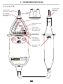 4
4
-
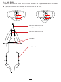 5
5
-
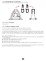 6
6
-
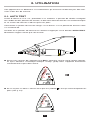 7
7
-
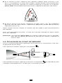 8
8
-
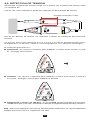 9
9
-
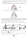 10
10
-
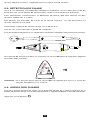 11
11
-
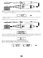 12
12
-
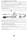 13
13
-
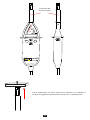 14
14
-
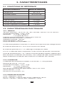 15
15
-
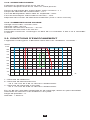 16
16
-
 17
17
-
 18
18
-
 19
19
-
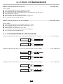 20
20
-
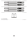 21
21
-
 22
22
-
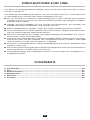 23
23
-
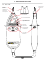 24
24
-
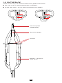 25
25
-
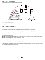 26
26
-
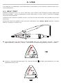 27
27
-
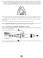 28
28
-
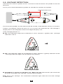 29
29
-
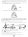 30
30
-
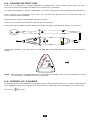 31
31
-
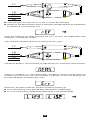 32
32
-
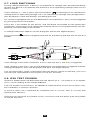 33
33
-
 34
34
-
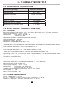 35
35
-
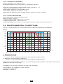 36
36
-
 37
37
-
 38
38
-
 39
39
-
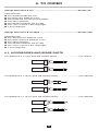 40
40
-
 41
41
-
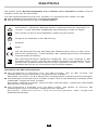 42
42
-
 43
43
-
 44
44
-
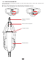 45
45
-
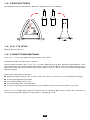 46
46
-
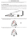 47
47
-
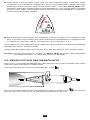 48
48
-
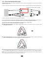 49
49
-
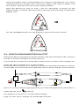 50
50
-
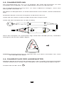 51
51
-
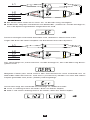 52
52
-
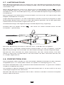 53
53
-
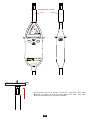 54
54
-
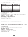 55
55
-
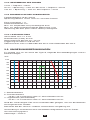 56
56
-
 57
57
-
 58
58
-
 59
59
-
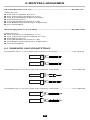 60
60
-
 61
61
-
 62
62
-
 63
63
-
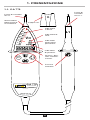 64
64
-
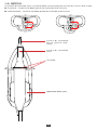 65
65
-
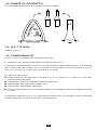 66
66
-
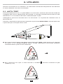 67
67
-
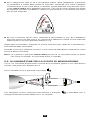 68
68
-
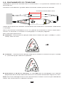 69
69
-
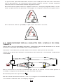 70
70
-
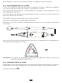 71
71
-
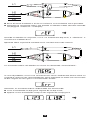 72
72
-
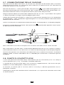 73
73
-
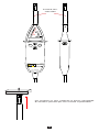 74
74
-
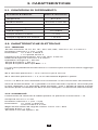 75
75
-
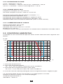 76
76
-
 77
77
-
 78
78
-
 79
79
-
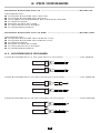 80
80
-
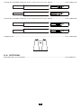 81
81
-
 82
82
-
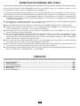 83
83
-
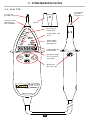 84
84
-
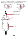 85
85
-
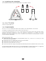 86
86
-
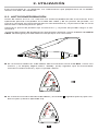 87
87
-
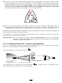 88
88
-
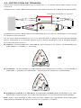 89
89
-
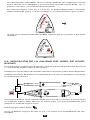 90
90
-
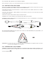 91
91
-
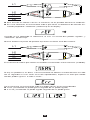 92
92
-
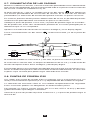 93
93
-
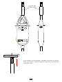 94
94
-
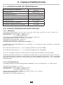 95
95
-
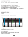 96
96
-
 97
97
-
 98
98
-
 99
99
-
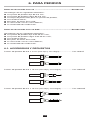 100
100
-
 101
101
-
 102
102
-
 103
103
-
 104
104


AEMC C.A 773 Manual de usuario
- Categoría
- Multimetros
- Tipo
- Manual de usuario
- Este manual también es adecuado para
En otros idiomas
- français: AEMC C.A 773 Manuel utilisateur
- italiano: AEMC C.A 773 Manuale utente
- English: AEMC C.A 773 User manual
- Deutsch: AEMC C.A 773 Benutzerhandbuch
Documentos relacionados

Otros documentos
-
CHAUVIN ARNOUX C.A 760 El manual del propietario
-
PeakTech P 1095 El manual del propietario
-
-
Facom 701A El manual del propietario
-
TESTBOY Profi III LCD Manual de usuario
-
Ideal 61-763 Guía del usuario
-