Graff G-11531 Guía de instalación
- Categoría
- Artículos sanitarios
- Tipo
- Guía de instalación

1
Dear Customer Estimado Cliente
Thank you for selecting our product. We are confident we can fully satisfy Muchas gracias por elegir nuestro producto. Estamos seguros que podemos
your expectations by offering you a wide range of technologically advanced satisfacer completamente sus expectativas ofreciéndole una amplia variedad
products which directly result from our many years of experience in faucet de productos tecnológicamente avanzados que resultan directamente de
and fitting production. muchos años de experiencia en grifos y su producción apropiada.
ENGLISH
~
ESPANOL
This faucet complies with NSF61/9, ASME/ANSI A112.18.1
and CSA B 125 Standards.
Este grifo se encuentra conforme con losestandares de NSF61/9,
de ASME/ANSI A112.18.1 y de CSA B 125. Installation Instructions Instrucciones de Instalación
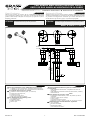
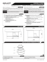
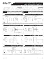
TWO HANDLE WALL-MOUNT LAVATORY FAUCET
GRIFO DE DOS MANILLAS MONTADOS EN LA PARED
Model
Modelo
For care, use soft towel with soap and water only! Under no
circumstances should you use any chemicals.
ATTENTION! ATENCIÓN! Para el cuidado, utilice solamente una toalla suave con jabón
y aqua! Bajo ninguna circunstancia no use productos químicos.
IOG 5207.70
MOD+
G-11531-***-L1**
Rev. 3 October 2020
For easy installation of your GRAFF faucet you will need:
to READ ALL the instructions completely before beginning,
to READ ALL the warnings, care and maintenance information.
To complete the project, you should:
gather the tools and all the parts you will need,
prepare the mounting area,
mount the faucet,
connect the supply lines,
finally test and flush the faucet.
You should have the following tools:
an adjustable spanner,
adjustable pliers,
Phillips screwdriver,
®
Teflon tape.
Para la instalación fácil de su grifo de la GRAFF usted
necesitará:
LEER TODAS las instrucciones
comenzar,
LEER TODA la información sobre las advertencias, cuidado y
mantenimiento
Para terminar el proyecto, usted debe:
recolectar las herramientas y todas las piezas que usted
necesitará,
prepare el área para el montaje,
monte el grifo,
conecte las líneas de fuente,
finalmente pruebe y limpie el grifo con un chorro de agua.
Usted debe tener las herramientas siguientes:
llave ajustable,
alicates acanalados,
desarmador Phillips, ®
cinta adhesiva de Teflon .
~
ESPANOL
ENGLISH
completamente antes de
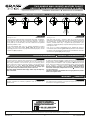
1-1/16"
(26mm)
1"
26mmO
8-7/16"
(215mm)Min.
Wall min.
9-1/4"
(235mm)
4"
102mmWall max.
3-1/8"
80mm
G-1012
8"
203mm
O2-1/4"
57mm

2
This faucet complies with NSF61/9, ASME/ANSI A112.18.1
and CSA B 125 Standards.
Este grifo se encuentra conforme con losestandares de NSF61/9,
de ASME/ANSI A112.18.1 y de CSA B 125. Installation Instructions Instrucciones de Instalación
IOG 5207.70
Rev. 3 October 2020
1
8
1
4
2
3
7
9.2 9.1
10
11
15
16
K2
K1
K3
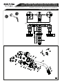
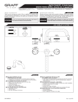
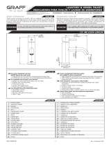
TWO HANDLE WALL-MOUNT LAVATORY FAUCET
GRIFO DE DOS MANILLAS MONTADOS EN LA PARED
Model
Modelo
MOD+
G-11530-***-L1**
5.1
5.2
6
12
13
14
1-1/16"
(26mm)
1"
26mmO
6-11/16"
(170mm)Min.
Wall min.
7-7/16"
(190mm)
4"
102mmWall max.
3-1/8"
80mm
G-1012
8"
203mm
O2-1/4"
57mm

3
This faucet complies with NSF61/9, ASME/ANSI A112.18.1
and CSA B 125 Standards.
Este grifo se encuentra conforme con losestandares de NSF61/9,
de ASME/ANSI A112.18.1 y de CSA B 125. Installation Instructions Instrucciones de Instalación
ENGLISH
~
ESPANOL
1
2
3
4
5
6
7
8
9
10
11
12
13
14
15
16
1
2
3
4
5
10
11
12
13
14
15
16
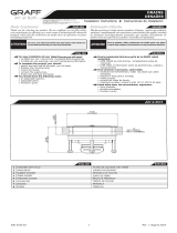
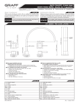
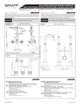
SPOUT
BODY OF AERATOR
CAÑO
K1
K2
K3
K1
K2
K3
IOG 5207.70
Rev. 3 October 2020
5.1
5.2
2.1
AERATOR INSERT CARTUCHO DEL PERLATOR
O-RING SEAL JUNTA TÓRICA
SCREW TORNILLO
VALVE FLANGE BRIDA DE LA VÁLVULA
CUERPO DEL AEREADOR
HANDLE PALANCA
HANDLE BODY
HANDLE COVER
CUERPO DE LA PALANCA
TAPA DE LA PALANCA
SLIDE WASHER ARANDELA DESLIZANTE
6.2
7
8
9
6
6.1
SPECIAL KEY FOR THE AERATOR
SCREW
HEX KEY 2,5MM
ESCUTCHEON
O-RING SEAL
SCREW
HEAD SPINDLE ELONGATION
HEX KEY 2MM
HANDLE INDICATOR
O-RING SEAL
SLEEVE
LLAVE ESPECIAL PARA EL AEREADOR
TORNILLO
LLAVE ALLÉN 2,5MM
ROSETA
JUNTA TÓRICA
TORNILLO
EXTENSIÓN DEL HUSO DE LA CABEZA
LLAVE ALLÉN 2MM
INDICADOR DE PALANCA
JUNTA TÓRICA
CASQUILLO
A
P1
Supply system
Instalación alimentadora
Finished wall
Pared de acabado
11
9
1
K2
A
~
ESPANOL
ENGLISH
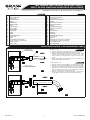
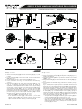
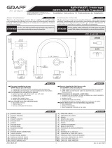
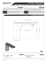
Take the asseembly cover (P1) off the spout nozzle (A) .
Slide the spout base (9) onto the spout nozzle (A).
Carefully slide the spout tip (1) onto the spout nozzle, while
making rotary motions with the spout. Make sure if the
O-ring seals are correctly placed in grooves of the spout
nozzle.
Set the spout (1) in proper position and secure it with screw
(11). Use the Allen key attached.
1.
2.
3.
4.
Quite la chapa de montaje (P1) de la válvula del caño (A) .
Coloque el florón para caño (9) en la válvula del caño (A).
Coloque con cuidado la punta del caño en la válvula del caño
(1) haciendo movimientos de rotación del caño. Asegúrese
que los selladores de anillo están correctamente posicio-
nados en las ranuras de la válvula del caño.
Coloque el caño (1)en la posición adecuada y apriételo con
tornillo (11). Utilice la llave hexagonal proporcionada.
1.
2.
3.
4.
See figs. 2.1-2.2
Verlaimagen 2.1-2.2
2.2
TWO HANDLE WALL-MOUNT LAVATORY FAUCET
GRIFO DE DOS MANILLAS MONTADOS EN LA PARED
SPOUT INSTALLATION • INSTALACIÓN DEL CAÑO

This faucet complies with NSF61/9, ASME/ANSI A112.18.1
and CSA B 125 Standards.
Este grifo se encuentra conforme con losestandares de NSF61/9,
de ASME/ANSI A112.18.1 y de CSA B 125. Installation Instructions Instrucciones de Instalación
4
IOG 5207.70
Rev. 3 October 2020
TWO HANDLE WALL-MOUNT LAVATORY FAUCET
GRIFO DE DOS MANILLAS MONTADOS EN LA PARED
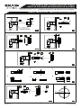
HANDLES INSTALLATION • INSTALACIÓN DE LAS MANILLAS
A8
Finished wall
Acabado de la pared
16 15
8
16 7 5
C
H
3.1 3.2
3.3 3.4
H
1. 2. 3.
4. 5. 6.
16 15
8
15
5
16
8513
3.5
3.6
3.7 3.8

This faucet complies with NSF61/9, ASME/ANSI A112.18.1
and CSA B 125 Standards.
Este grifo se encuentra conforme con losestandares de NSF61/9,
de ASME/ANSI A112.18.1 y de CSA B 125. Installation Instructions Instrucciones de Instalación
5
IOG 5207.70
Rev. 3 October 2020
TWO HANDLE WALL-MOUNT LAVATORY FAUCET
GRIFO DE DOS MANILLAS MONTADOS EN LA PARED
~
ESPANOL
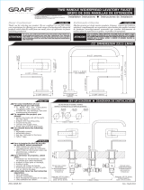
See figs. 3.1-3.15 Ver. fig. 3.1-3.15
ENGLISH
5
K3 6
13
3.14 3.15
Precisely cut off the installation cover.
Screw a mounting flange (8) into the valve sleeve (C) (fig. 3.1) until
it stops.
Put an extension (16) on the valve spindle. Connct it with a screw
(15) (fig. 3.2).
Put the handle (5) onto valve extensions (16) (fig. 3.3).
If the extension is too long, cut it off with the screw (see fig.
3.4-3.7).
Place the lever (5) on the valve spindle extension (16) - fig. 3.8.
Check whether it is possible to get the valve setting according to fig.
3.16. If a satisfactory lever (5) setting cannot be reached (a
significant Δ angle displacement in relation to the required setting
can be seen - such as in the fig. 3.9) remove the lever (5) from the
valve spindle extension (16) - fig. 3.11. Unscrew the screw (15)
and put the valve spindle extension (16) one tooth off on the valve
head spline and screw the screw (15) back. - fig. 3.121-3.13. Again
put the lever (5) on the valve spindle extension (16) and check
whether the lever setting is correct (5) - fig. 3.16:
1.
2.
3.
4.
5.
6.
If the lever (5) setting is correct, tighten the bolt (6) with an
allen wrench (K3) in accordance with fig. 3.15.
If the setting of the lever (5) is still incorrect - put the valve
spindle extension (16) off by another tooth on the valve head
spline and check the lever setting correctness again (5).
●
●
1.
2.
3.
4.
5.
6.
Corta con precisión las tapas de montaje.
Atornille una brida de montaje (8) al manguito válvula (C) (fig. 3.1)
hasta que se detenga.
Ponga una extensión (16) en el eje válvula. Conéctelo a un tornillo
(15) (fig. 3.2).
Ponga la manecilla (5) sobre las extensiones de la válvula (16) (fig.
3.3).
Si la extensión es demasiado larga, córtela con el tornillo (ver fig.
3.4-3.7).
Ponga la maneta (5) en la extensión del husillo de la válvula (16) -
fig. 3.8. Verifique si es posible ajustar la válvula de acuerdo con la
figura 3.16. Si no se puede ajustar la maneta (5) de forma satisfac-
toria respecto al borde del lavabo (es posible ver un desplazamiento
del ángulo Δ significativo en relación con el ajuste requerido, como
en la fig. 3.9) extraiga las manetas (5) de la extensión del husillo de
la válvula (16) - fig. 3.10. Desenrosque el tornillo (15) y ponga la
extensión del husillo de la válvula (16) un diente fuera del cabezal
roscado de la válvula y enrosque el tornillo (15) Vuelva a poner la
maneta (5) en la extensión roscada de la válvula (16) y verifique si
el ajuste de la maneta es correcto (5) - fig. 3.16:
Si el ajuste de la maneta (5) es correcto, apriete el perno (6) con
una llave hexagonal (K3) de acuerdo con la fig. 3.15
Si el ajuste de la maneta (5) sigue siendo incorrecto ponga otro
diente en la extensión del husillo de la válvula (16) fuera del
cabezal roscado de la válvula y verifique de nuevo si el ajuste de
la maneta (5) es correcto.
●
●
16 513
16 5
3.9 3.10
3.11 3.12 3.13

This faucet complies with NSF61/9, ASME/ANSI A112.18.1
and CSA B 125 Standards.
Este grifo se encuentra conforme con losestandares de NSF61/9,
de ASME/ANSI A112.18.1 y de CSA B 125. Installation Instructions Instrucciones de Instalación
6
IOG 5207.70
Rev. 3 October 2020
ENGLISH
~
ESPANOL
CARE AND MAINTENANCE CUIDADO Y MANTENIMIENTO
ENGLISH
~
ESPANOL
WARRANTY GARANTÍA
All dimensions and drawings are for reference only. For details, please refer to actual products.
Todas las dimensiones y dibujos sirven únicamente de referencia. Para consultar detalles, ver los productos.
Your Graff faucet is designed and engineered in accordance with the
highest quality and performance standards. Be sure not to damage the
finish during installation. Care should be given to the cleaning of this
product. Although its finish is extremely durable, it can be damaged by
harsh abrasives or polish. Never use abrasive cleaners, acids,
solvents, etc. to clean any Graff product. To clean, simply wipe
gently with a damp cloth and blot dry with a soft towel.
Warranty conditions and warranty registration card are outlined on a
separate sheet.
Su grifo de la Graff esta dise ado y dirigido acuerdo con los estándares de
funcionamiento y calidad más altos. Este seguro no da ar las terminaciones
del grifo durante la instalación. Cuide el producto manteniendolo siempre
limpio. Aunque su acabado es extremadamente durable, puede ser da ado
por los abrasivos o pulientes ásperos. Nunca utilice limpiadores
abrasivos, ácidos, solventes, el etc. para limpiar cualquier producto
de la Graff. Para limpiar, simplemente use un pa o húmedo y seque
con una toalla suave.
Las condiciones de la garantía y la tarjeta del registro de la garantía se
encuentran en una pagina separada.
~
ESPANOL
ENGLISH
Clean the marble elements with soapy water only and wipe dry
with a soft cloth. Limpie los elementos de mármol sólo con agua jabonosa, frotán-
dolos con un paño suave
OPERATING INSTRUCTIONS LA DESCRIPCIÓN DEL FUNCIONAMIENTO
TWO HANDLE WALL-MOUNT LAVATORY FAUCET
GRIFO DE DOS MANILLAS MONTADOS EN LA PARED
www.graff-designs.com
OFF
OFF ON
ON
4.1 4.2
The levers open water discharge and regulate water flow. The dischar-
ge is fully open when the lever is turned 90° (clockwise – cold water
lever (label C) on the right side, and counter clockwise – hot water
lever (label H) on the left side). The rate of water flow is regulated
between positions 0°-90°.
It is recommended that every 3-6 months (depending on water
quality) you remove the aerator (item 2, fig. 1) from the faucet
spout (1) in order to remove any impurities. For this purpose, use the
special key (K1) (supplied).
Para dejar salir el agua y ajustar el flujo de la misma sirven las
palancas. La apertura total ocurre al girar la palanca por el ángulo de
90 (sentido reloj – la palanca del agua fría (“C”) colocada por el lado
derecho, sentido contra reloj – la palanca del agua caliente (“H”)
colocada por el lado izquierdo). El ajuste del flujo del agua se hace en
el rango de 0°-90°.
Una vez a 3-6 meses (dependiendo de la calidad del agua) se
recomienda quitar el difusor (pos. 2 dis. 1) del caño de la mezclado-
ra (1) con el fin de limpiarlo de todo tipo de ensuciamiento. Para eso
use una llave especial (K1) anexa al juego.
See figs. 4.1-4.2 Ver. fig. 4.1-4.2
-
 1
1
-
 2
2
-
 3
3
-
 4
4
-
 5
5
-
 6
6


Graff G-11531 Guía de instalación
- Categoría
- Artículos sanitarios
- Tipo
- Guía de instalación
En otros idiomas
- English: Graff G-11531 Installation guide
Documentos relacionados
-
 Graff G-9972 Guía de instalación
-
 Graff G-2311-LM40-SN Guía de instalación
-
 Graff G-09949 Guía de instalación
-
 Graff G-6751-C19B Guía de instalación
-
 Graff G-6251-LM39B Guía de instalación
-
 Graff G-6153-LM41B Guía de instalación
-
 Graff G-6135-LM41W-PC Guía de instalación
-
 Graff G-6104-LM41M Guía de instalación
-
 Graff G-3896-C2 Guía de instalación
-
 Graff Faucets G-6300-LM42-PC Guía de instalación


