Generac iX1400 G0058420 Manual de usuario
- Categoría
- Generadores de poder
- Tipo
- Manual de usuario

www.generac.com or 1-888-GENERAC
iX 1400
Digital Inverter Generator Operator's Manual
MODEL: 005842-0
DEADLY EXHAUST FUMES! ONLY use OUTSIDE
far away from windows, doors and vents.
NOT for use in critical life support applications.
SAVE this Manual. Provide this manual to any
operator of the generator.

Accessory Box ..............................................Inside Front Cover
Introduction ..............................................................................1
Read this Manual Thoroughly ..................................................1
Safety Rules ............................................................................1
Standards Index ...............................................................3
General Information .................................................................4
Specifications ...........................................................................4
Emissions Information ......................................................4
Unit Identification ......................................................................4
Control Panel....................................................................5
Operation .................................................................................5
Pre-Use Check ..........................................................................5
Starting the Generator ...............................................................6
Adding Loads ............................................................................6
Using the FlexPower
™
Switch ...................................................7
Using the 12 VDC Battery Charger ............................................7
Shutting Down ..........................................................................7
Low Oil Level Shutdown ............................................................8
Fueling the Generator ................................................................8
To Fill the Fuel Tank ..........................................................8
Adding Engine Oil ......................................................................8
To Add Engine Oil to the Crankcase ..................................8
Maintenance ............................................................................9
Generator Maintenance .............................................................9
Generator Maintenance Schedule ..............................................9
Cleaning the Generator ..............................................................9
Engine Maintenance ................................................................10
Changing the Engine Oil ..........................................................10
Changing the Fuel Filter ...........................................................10
Changing the Spark Plug .........................................................11
Transportation and Storage .....................................................11
Clean Spark Arrestor Screen ...................................................12
Troubleshooting .....................................................................13
Troubleshooting Guide .............................................................13
ACCESSORY BOX
Check all contents. If any parts are missing or damaged locate an
authorized dealer at 1-888-436-3722.
Contents include:
• 1 bottle SAE 30 Oil • Oil Funnel
• Spark Plug Wrench • Screwdriver
• Battery Charge Cable
Table of Contents
WARNING!
California Proposition 65
Engine exhaust and some of its constituents are known to the state of California to cause cancer,
birth defects, and other reproductive harm.
WARNING!
California Proposition 65
This product contains or emits chemicals known to the state of California to cause cancer,
birth defects, and other reproductive harm.

INTRODUCTION
Thank you for purchasing this model by Generac Power Systems,
Inc. This model is a compact, high performance, air-cooled,
engine driven generator designed to supply electrical power to
operate electrical loads where no utility power is available or in
place of utility due to a power outage.
READ THIS MANUAL THOROUGHLY
If any portion of this manual is not understood, contact the
nearest Authorized Dealer for starting, operating and servicing
procedures.
The operator is responsible for proper and safe use of the
equipment. We strongly recommend that the operator read this
manual and thoroughly understand all instructions before using the
equipment. We also strongly recommend instructing other users to
properly start and operate the unit. This prepares them if they need
to operate the equipment in an emergency.
The generator can operate safely, efficiently and reliably only if it
is properly located, operated and maintained. Before operating or
servicing the generator:
• Become familiar with and strictly adhere to all local, state and
national codes and regulations.
• Study all safety warnings in this manual and on the product
carefully.
• Become familiar with this manual and the unit before use.
The manufacturer cannot anticipate every possible circumstance
that might involve a hazard. The warnings in this manual, and on
tags and decals affixed to the unit are, therefore, not all inclusive.
If using a procedure, work method or operating technique that the
manufacturer does not specifically recommend, ensure that it is
safe for others. Also make sure the procedure, work method or
operating technique utilized does not render the generator unsafe.
THE INFORMATION CONTAINED HEREIN WAS BASED ON
MACHINES IN PRODUCTION AT THE TIME OF PUBLICATION.
GENERAC RESERVES THE RIGHT TO MODIFY THIS MANUAL AT
ANY TIME.
SAFETY RULES
Throughout this publication, and on tags and decals affixed to the
generator, DANGER, WARNING, CAUTION and NOTE blocks are
used to alert personnel to special instructions about a particular
operation that may be hazardous if performed incorrectly or
carelessly. Observe them carefully. Their definitions are as
follows:
Indicates a hazardous situation or action which, if
not avoided, will result in death or serious injury.
Indicates a hazardous situation or action which,
if not avoided, could result in death or serious
injury.
Indicates a hazardous situation or action which,
if not avoided, could result in minor or moderate
injury.
NOTE:
Notes contain additional information important to a procedure
and will be found within the regular text body of this manual.
These safety warnings cannot eliminate the hazards that they
indicate. Common sense and strict compliance with the special
instructions while performing the action or service are essential to
preventing accidents.
Four commonly used safety symbols accompany the DANGER,
WARNING and CAUTION blocks. The type of information each
indicates is as follows:
This symbol points out important safety
information that, if not followed, could
endanger personal safety and/or property of
others.
This symbol points out potential explosion
hazard.
This symbol points out potential fire hazard.
This symbol points out potential electrical
shock hazard.
GENERAL HAZARDS
• NEVER operate in an enclosed area, in a vehicle, or indoors
EVEN IF doors and windows are open.
• For safety reasons, the manufacturer recommends that the
maintenance of this equipment is carried out by an Authorized
Dealer. Inspect the generator regularly, and contact the nearest
Authorized Dealer for parts needing repair or replacement.
• Operate generator only on level surfaces and where it will not be
exposed to excessive moisture, dirt, dust or corrosive vapors.
• Keep hands, feet, clothing, etc., away from drive belts, fans,
and other moving parts. Never remove any fan guard or shield
while the unit is operating.
• Certain parts of the generator get extremely hot during
operation. Keep clear of the generator until it has cooled to
avoid severe burns.
• Do NOT operate generator in the rain.
• Do not alter the construction of the generator or change controls
which might create an unsafe operating condition.
• Never start or stop the unit with electrical loads connected
to receptacles AND with connected devices turned ON. Start
the engine and let it stabilize before connecting electrical
loads. Disconnect all electrical loads before shutting down the
generator.
1
Safety Rules

2
• When working on this equipment, remain alert at all times.
Never work on the equipment when physically or mentally
fatigued.
• Never use the generator or any of its parts as a step. Stepping
on the unit can stress and break parts, and may result in
dangerous operating conditions from leaking exhaust gases,
fuel leakage, oil leakage, etc.
EXHAUST & LOCATION HAZARDS
• Never operate in an enclosed area or indoors! NEVER use
in the home, in a vehicle, or in partly enclosed areas such
as garages, even if doors and windows are open! ONLY use
outdoors and far from open windows, doors, vents, and in an
area that will not accumulate deadly exhaust.
• The engine exhaust fumes contain carbon monoxide, which
you cannot see or smell. This poisonous gas, if breathed in
sufficient concentrations, can cause unconsciousness or even
death.
• Adequate, unobstructed flow of cooling and ventilating air
is critical to correct generator operation. Do not alter the
installation or permit even partial blockage of ventilation
provisions, as this can seriously affect safe operation of the
generator. The generator MUST be operated outdoors.
• This exhaust system must be properly maintained. Do nothing
that might render the exhaust system unsafe or in noncompliance
with any local codes and/or standards.
• Always use a battery operated carbon monoxide alarm indoors,
installed according to the manufacturers instructions.
• If you start to feel sick, dizzy, or weak after the generator has
been running, move to fresh air IMMEDIATELY. See a doctor, as
you could have carbon monoxide poisoning.
ELECTRICAL HAZARDS
• The generator produces dangerously high voltage when in
operation. Avoid contact with bare wires, terminals, connections,
etc., while the unit is running, even on equipment connected
to the generator. Ensure all appropriate covers, guards and
barriers are in place before operating the generator.
• Never handle any kind of electrical cord or device while
standing in water, while barefoot or while hands or feet are wet.
DANGEROUS ELECTRICAL SHOCK MAY RESULT.
• The National Electric Code (NEC) requires the frame and external
electrically conductive parts of the generator be properly
connected to an approved earth ground. Local electrical codes
may also require proper grounding of the generator. Consult
with a local electrician for grounding requirements in the area.
• Use a ground fault circuit interrupter in any damp or highly
conductive area (such as metal decking or steel work).
• Do not use worn, bare, frayed or otherwise damaged electrical
cord sets with the generator.
• In case of accident caused by electric shock, immediately shut
down the source of electrical power. If this is not possible,
attempt to free the victim from the live conductor. AVOID
DIRECT CONTACT WITH THE VICTIM. Use a non-conducting
implement, such as a rope or board, to free the victim from the
live conductor. If the victim is unconscious, apply first aid and
get immediate medical help.
FIRE HAZARDS
• Gasoline is highly FLAMMABLE and its vapors are EXPLOSIVE.
Do not permit smoking, open flames, sparks or heat in the
vicinity while handling gasoline.
• Never add fuel while unit is running or hot. Allow engine to
cool completely before adding fuel.
• Never fill fuel tank indoors. Comply with all laws regulating
storage and handling of gasoline.
• Do not overfill the fuel tank. Always allow room for fuel
expansion. If tank is over-filled, fuel can overflow onto a hot
engine and cause FIRE or an EXPLOSION. Never store generator
with fuel in tank where gasoline vapors might reach an open
flame, spark or pilot light (as on a furnace, water heater or
clothes dryer). FIRE or EXPLOSION may result. Allow unit to
cool entirely before storage.
• Wipe up any fuel or oil spills immediately. Ensure that no
combustible materials are left on or near the generator. Keep the
area surrounding the generator clean and free from debris and
keep a clearance of five (5) feet on all side to allow for proper
ventilation of the generator.
• Do not insert objects through unit’s cooling slots.
Save These Instructions – The manufacturer suggests that these rules for safe operation be copied
and posted near the unit's installation site. Safety should be stressed to all operators and potential
operators of this equipment. If you loan this unit to anyone, be sure to also loan this Owner's Manual
and advise that it be read thoroughly before operating the unit.
Safety Rules

• Do not operate the generator if connected electrical devices
overheat, if electrical output is lost, if engine or generator sparks
or if flames or smoke are observed while unit is running.
• Keep a fire extinguisher near the generator at all times.
STANDARDS INDEX
1. National Fire Protection Association (NFPA) 70: The NATIONAL
ELECTRIC CODE (NEC) available from www.nfpa.org
2. National Fire Protection Association (NFPA) 5000: BUILDING
CONSTRUCTION AND SAFETY CODE available from www.
nfpa.org
3. International Building Code available from www.iccsafe.org
4. Agricultural Wiring Handbook available from www.rerc.org ,
Rural Electricity Resource Council P.O. Box 309 Wilmington,
OH 45177-0309
5. ASAE EP-364.2 Installation and Maintenance of Farm Standby
Electric Power available from www.asabe.org, American
Society of Agricultural & Biological Engineers 2950 Niles
Road, St. Joseph, MI 49085
This list is not all inclusive. Check with the Authority Having Local
Jurisdiction (AHJ) for any local codes or standards which may be
applicable to your jurisdiction.
MODEL NO:
SERIAL NO:
Figure 1 - Generator ID Plate
ID PLATE
3
Safety Rules

4
SPECIFICATIONS
Engine Type . . . . . . . . . . . . . . . . . . . . . . . . Single Cylinder, 4-Stroke
Engine Size . . . . . . . . . . . . . . . . . . . . . . . . . . . . . . . . . . . . . . . 80cc
Starter Type . . . . . . . . . . . . . . . . . . . . . . . . . . . . . . . . . . . . . . Recoil
Fuel Capacity/Type . . . . . . . . . . . . . . . . . 0.73 Gal (2.77 L)/Unleaded
Oil Capacity . . . . . . . . . . . . . . . . . . . . . . . . . . . . . . . . 0.63 Qt (0.6L)
Runtime Full/Half Load . . . . . . . . . . . . . . . . . . . . . . . . 2.5/5.0 Hours
Spark Plug Type. . . . . . . . . . . . . . . . . . . . . . . . . . . . . . . . . BPR7HS
Spark Plug Gap . . . . . . . . . . . . . . . . . . . . . . . . . . . . . . . . . . . ..030”
Dimensions L x W x H (in) . . . . . . . . . . . . . . . . . . . . . . 22 x 12 x 18
Weight Lb/kg . . . . . . . . . . . . . . . . . . . . . . . . . . . . . . . . . 46.0/20.09
Maximum AC Output . . . . . . . . . . . . . . . . . . . . . . . . . . . . . . 1400W
Surge AC Output . . . . . . . . . . . . . . . . . . . . . . . . . . . . . . . . . 1450W
AC Volts. . . . . . . . . . . . . . . . . . . . . . . . . . . . . . . . . . . . . . . 120 VAC
Rated AC Current . . . . . . . . . . . . . . . . . . . . . . . . . . . . . . . . . .11.6 A
Frequency . . . . . . . . . . . . . . . . . . . . . . . . . . . . . . . . . . . . . . . 60 Hz
THD. . . . . . . . . . . . . . . . . . . . . . . . . . . . . . . . . . . . . . . . . . . . . 3.0%
Insulation Class . . . . . . . . . . . . . . . . . . . . . . . . . . . . . . . . . . Class B
Outlets. . . . . . . . . . . . . . . . . . . . . . . . . . . . . .(2) 5-15R, (1) 12 VDC
DC Volts. . . . . . . . . . . . . . . . . . . . . . . . . . . . . . . . . . . . . . . . 12 VDC
Rated DC Current. . . . . . . . . . . . . . . . . . . . . . . . . . . . . . . . . . . . 5 A
NOTE:
Power output and runtime are influenced by many factors,
some of which are fuel quality, ambient temperature and engine
condition. Output decreases approximately 3.5% for each 1,000
feet above sea level and 1% for every 10 degrees above 60°F.
EMISSIONS INFORMATION
The Environmental Protection Agency (EPA) and California Air
Resource Board (CARB) require that your generator comply with
exhaust and evaporative emission standards. This generator is
certified to meet the applicable EPA and CARB emission levels.
Additional information regarding the requirements set by EPA and
CARB is as follows:
It is important that you follow the maintenance specifications
provided in this manual to ensure that your engine complies with
the applicable emission standards for the duration of the engine’s
life. This engine is certified to operate on gasoline. The emission
control system on your generator consists of the following:
• Fuel System • Air Induction System
~ Fuel Tank ~ Intake pipe/manifold
~ Fuel Cap ~ Air cleaner
~ Carburetor • Ignition System
~ Fuel Lines ~ Spark plug
• Evaporative Control System ~ Ignition module
~ Carbon Canister • Exhaust System
~ Vapor Hoses ~ Pulse Air Injection Valve
~ Muffler
The Emissions Compliance Period referred to on the Emissions
Compliance Label indicates the number of operating hours for
which the engine has been shown to meet Federal and California
emission requirements. See the table below to determine the
compliance period for your generator. The displacement of your
generator is listed on the Emissions Compliance Label.
UNIT IDENTIFICATION (Figure 2)
1. Carrying Handle: Lift the generator by this handle only.
2. Spark Plug Cover: Allows access to the engine spark plug.
3. Fuel System Primer: Used to prime the fuel system for
starting.
4. Fuel Cap Pressure Valve: Allows air to enter the fuel tank to
equalize pressure.
5. Fuel Tank Cap: Access to fuel tank for filling.
6. Control Panel: location of generator controls and output
receptacles.
7. Air Intake Slats: Allows for cooling air to enter the housing.
8. Muffler: Lowers engine exhaust noise (includes the spark
arrestor).
9. Choke: Cold engine starting aid
10. Left Side Service Cover: Allows access to air filter, fuel filter
and oil fill.
11. Vent Hoses: Hoses allow venting of the carburetor.
12. Fuel Shutoff: Controls fuel supply to the carburetor.
13. Starter Rope: Pull rope for starting engine.
Figure 2 - Unit Identification
1
2
3
4
5
6
7
8
9
10
11
12
13
4
General Information

55
CONTROL PANEL (Figure 3)
14. LOW OIL LEVEL LED (yellow): Lights up when oil level is
below safe operating level and the engine shuts down..
15. OVERLOAD LED (red): Lights up if the generator experiences
a load greater than the rated output, low voltage, overheats or
the powered circuit experiences a short. The output is stopped
even though the engine keeps running.
16. READY LED (green): Indicates output from the generator
unless there is a low oil or overload condition.
17. 12 VDC Plug: Connection for re-charging 12VDC automotive-
style batteries while generator is in operation.
18. FlexPower™ Switch: This switch slows the engine speed
when the load is reduced to save fuel and engine wear.
19. 12 VDC Circuit Breaker: Overload protection for the 12 VDC
charging system.
20. Ground (Earth) Connection Lug: Grounding point for the
generator; consult state and local electrical codes before use
(floating ground).
21. 120 VAC Receptacles: Two (2) receptacles for connecting
accessories.
NOTE:
Do not exceed the rated output of the generator.
Figure 3 - Control Panel
14
15
16
17
18
19
20
21
PRE-USE CHECK
Prior to starting the generator and adding loads, perform the
following tasks:
1. Make sure the generator is on a firm, level (not to exceed 15°
in any direction), non-combustible surface with at least five
(5) feet of clearance on all sides.
Never operate in an enclosed area or
indoors! NEVER use in the home, in a
vehicle, or in partly enclosed areas such
as garages, even if doors and windows are
open! ONLY use outdoors and far from open
windows, doors, vents, and in an area that
will not accumulate deadly exhaust.
2. Remove the fuel cap and check the fuel level. If fuel is needed,
see the section “FUELING THE GENERATOR”.
3. Remove the left side service cover and check the oil level
by removing the oil filler cap. The oil level should be to the
bottom of the threads on the oil fill pipe. If oil is needed, see
the section “ADDING ENGINE OIL”.
4. Replace and secure the left side service cover.
5. Make sure there are no loads connected to the generator.
6. The National Electric Code (NEC) requires the frame and
external electrically conductive parts of the generator be
properly connected to an approved earth ground. Proper
grounding of the generator will prevent electrical shock in
the event of a ground fault condition in the generator or in
connected electrical devices. Proper grounding also helps
dissipate static electricity, which often builds up in unguarded
devices.
7. Local electrical codes may also require proper grounding of
the generator.
Starting the generator with accessories
connected to the 120 VAC outlets will
damage the generator and the connected
accessories.
Operation

6 6
STARTING THE GENERATOR
Once the fuel and oil levels have been checked and it has been
verified there are no loads connected, the generator may be
started. Turn the FlexPower Switch OFF (O).
1. Open the fuel valve (Figure 4), located below the starter rope
pull, by turning to the valve 90° counter-clockwise to the “ON”
(I) position.
2. Pull up on the center of the fuel fill cap and prime the fuel
system by depressing the plunger up to five (5) times with the
vent closed (Figure 5 on next page).
3. Open the fuel tank vent on the top of the fuel fill cap by turning
the center portion to the “ON” mark (Figure 6 on next page).
4. If the engine is cold or has not been run for some time, engage
the choke by pushing the choke lever to the right.
5. Grip the handle for the pull starter and brace your other hand
against the generator. Pull the rope slowly until resistance is
felt, then pull the rope rapidly.
Figure 4 - Fuel Valve
TURNING THE FUEL ON
6. If the engine does not start, repeat steps 2-5 until the engine
fires and begins to run.
7. Carefully adjust the choke to approximately the ½ position
until the engine begins to run smoothly, then push the lever all
the way to the left (Figure 6).
8. Make sure the bottom of the generator is not blocked by sand,
leaves, grass, etc. as the cooling vents are located on the
bottom of the unit.
Figure 5 - Prime Fuel System
FUEL
SYSTEM
VENT
PLUNGER
VENT
Figure 6 - Adjust Choke
ENGINE CHOKE
OPERATION
ON
I
OFF
O
ADDING LOADS
Once the generator has been running smoothly for 2-3 minutes,
electrical loads can be added.
Do not use worn, bare, frayed or otherwise
damaged electrical cord sets with the
generator. Do not handle any kind of electrical
device while standing in water, while barefoot,
or while hands or feet are wet.
1. There are two grounded 120 VAC duplex outlets on the front
of the generator.
2. DO NOT overload the generator; if the red “overload” LED
lights up and the accessories attached to the generator
stop operating, stop the engine and reduce the load to the
generator. Restart and apply reduced loads.
3. Consult the following table to estimate what can be powered
by the generator.
Device . . . . . . . . . . . . . . . . . . . . . . . . . . . . . . . .Running Watts
*Air Conditioner (12,000 Btu) . . . . . . . . . . . . . . . . . . . . . . . . .1700
*Air Conditioner (24,000 Btu) . . . . . . . . . . . . . . . . . . . . . . . . .3800
*Air Conditioner (40,000 Btu) . . . . . . . . . . . . . . . . . . . . . . . . .6000
Battery Charger (20 Amp) . . . . . . . . . . . . . . . . . . . . . . . . . . . . . 500
Belt Sander (3") . . . . . . . . . . . . . . . . . . . . . . . . . . . . . . . . . . . . 1000
Chain Saw . . . . . . . . . . . . . . . . . . . . . . . . . . . . . . . . . . . . . . . . 1200
Circular Saw (6-1/2"). . . . . . . . . . . . . . . . . . . . . . . . . . 800 to 1000
*Clothes Dryer (Electric) . . . . . . . . . . . . . . . . . . . . . . . . . . . . . 5750
*Clothes Dryer (Gas) . . . . . . . . . . . . . . . . . . . . . . . . . . . . . . . . . 700
*Clothes Washer . . . . . . . . . . . . . . . . . . . . . . . . . . . . . . . . . . . 1150
Coffee Maker . . . . . . . . . . . . . . . . . . . . . . . . . . . . . . . . . . . . . . 1750
*Compressor (1 HP) . . . . . . . . . . . . . . . . . . . . . . . . . . . . . . . .2000
*Compressor (3/4 HP). . . . . . . . . . . . . . . . . . . . . . . . . . . . . . . 1800
*Compressor (1/2 HP). . . . . . . . . . . . . . . . . . . . . . . . . . . . . . . 1400
Curling Iron . . . . . . . . . . . . . . . . . . . . . . . . . . . . . . . . . . . . . . . . 700
*Dehumidifier . . . . . . . . . . . . . . . . . . . . . . . . . . . . . . . . . . . . . . 650
Disc Sander (9") . . . . . . . . . . . . . . . . . . . . . . . . . . . . . . . . . . . 1200
Edge Trimmer . . . . . . . . . . . . . . . . . . . . . . . . . . . . . . . . . . . . . . 500
Electric Blanket . . . . . . . . . . . . . . . . . . . . . . . . . . . . . . . . . . . . . 400
Electric Nail Gun. . . . . . . . . . . . . . . . . . . . . . . . . . . . . . . . . . . . 1200
Electric Range (per element) . . . . . . . . . . . . . . . . . . . . . . . . . . 1500
Electric Skillet . . . . . . . . . . . . . . . . . . . . . . . . . . . . . . . . . . . . . 1250
*Freezer. . . . . . . . . . . . . . . . . . . . . . . . . . . . . . . . . . . . . . . . . . . 700
*Furnace Fan (3/5 HP). . . . . . . . . . . . . . . . . . . . . . . . . . . . . . . . 875
Operation

7
*Garage Door Opener. . . . . . . . . . . . . . . . . . . . . . . . . . . 500 to 750
Hair Dryer . . . . . . . . . . . . . . . . . . . . . . . . . . . . . . . . . . . . . . . . 1200
Hand Drill. . . . . . . . . . . . . . . . . . . . . . . . . . . . . . . . . . . 250 to 1100
Hedge Trimmer . . . . . . . . . . . . . . . . . . . . . . . . . . . . . . . . . . . . . 450
Impact Wrench . . . . . . . . . . . . . . . . . . . . . . . . . . . . . . . . . . . . . 500
Iron . . . . . . . . . . . . . . . . . . . . . . . . . . . . . . . . . . . . . . . . . . . . . 1200
*Jet Pump . . . . . . . . . . . . . . . . . . . . . . . . . . . . . . . . . . . . . . . . . 800
Lawn Mower . . . . . . . . . . . . . . . . . . . . . . . . . . . . . . . . . . . . . . 1200
Light Bulb . . . . . . . . . . . . . . . . . . . . . . . . . . . . . . . . . . . . . . . . . 100
Microwave Oven . . . . . . . . . . . . . . . . . . . . . . . . . . . . . 700 to 1000
*Milk Cooler . . . . . . . . . . . . . . . . . . . . . . . . . . . . . . . . . . . . . .1100
Oil Burner on Furnace. . . . . . . . . . . . . . . . . . . . . . . . . . . . . . . . . 300
Oil Fired Space Heater (140,000 Btu) . . . . . . . . . . . . . . . . . . . . . 400
Oil Fired Space Heater (85,000 Btu) . . . . . . . . . . . . . . . . . . . . . . 225
Oil Fired Space Heater (30,000 Btu) . . . . . . . . . . . . . . . . . . . . . . 150
*Paint Sprayer, Airless (1/3 HP) . . . . . . . . . . . . . . . . . . . . . . . . . 600
Paint Sprayer, Airless (handheld) . . . . . . . . . . . . . . . . . . . . . . . . 150
Radio. . . . . . . . . . . . . . . . . . . . . . . . . . . . . . . . . . . . . . . . 50 to 200
*Refrigerator . . . . . . . . . . . . . . . . . . . . . . . . . . . . . . . . . . . . . . . 700
Slow Cooker . . . . . . . . . . . . . . . . . . . . . . . . . . . . . . . . . . . . . . . 200
*Submersible Pump (1-1/2 HP) . . . . . . . . . . . . . . . . . . . . . . . . 2800
*Submersible Pump (1 HP) . . . . . . . . . . . . . . . . . . . . . . . . . . . 2000
*Submersible Pump (1/2 HP). . . . . . . . . . . . . . . . . . . . . . . . . . 1500
*Sump Pump. . . . . . . . . . . . . . . . . . . . . . . . . . . . . . . . 800 to 1050
* Allow three (3) times the listed running watts for starting theses devices.
NOTE:
When an electric motor is started, the "OVERLOAD" LED may
light up for up to five (5) seconds (this is normal). If it stays on,
a fault has occured. Remove all loads and shut down generator
to reset the alarm. Restart the generator. If the "OVERLOAD"
LED remains lit, contact a Generac Dealer for assistance.
USING THE FLEXPOWER™ SWITCH
When the accessories connected to the generator are going to
be used intermittently (such as a hand drill), the FlexPower™
switch can be pushed to the “ON” (I) position. This will lower the
generator engine speed when loads are not being applied, saving
fuel, reducing engine wear and extending runtime.
USING THE 12 VDC BATTERY CHARGER
The 12 VDC receptacle may be used to recharge 12 VDC
automotive batteries only. The DC charging output is not regulated.
The circuit protector does not prevent over-charging a battery.
1. Connect the charging cable to the generator first, then the
battery, ALWAYS connecting the red lead to positive (+) and
the black to negative (-).
Do not permit smoking, open flame, sparks
or any other source of heat around a battery.
Wear protective goggles, rubber apron
and rubber gloves when working around
a battery. Battery electrolyte fluid is an
extremely corrosive sulfuric acid solution
that can cause severe burns. If a spill occurs,
flush area with clear water immediately.
Storage batteries give off explosive hydrogen
gas while recharging. An explosive mixture
will remain around the battery for a long
time after it has been charged. The slightest
spark can ignite the hydrogen and cause an
explosion. Such an explosion can shatter the
battery and cause blindness or other serious
injury.
NEVER reverse the polarity when connecting
the battery terminals to the charging jack.
Severe damage may occur to the generator
and battery.
2. Keep the FlexPower™ switch in the “OFF” (O) position.
3. Start the generator and use it as normal. Charging time will
vary with battery size and condition. Check the voltage at the
battery terminals once the charging cable has been unplugged
or the generator has been shut down.
NOTE:
This receptacle can not recharge 6-Volt batteries and can not
be used to crank an engine having a discharged battery.
SHUTTING DOWN
Once the generator is no longer needed it can be shut down.
1. Switch off any accessories connected to the generator. Unplug
any cords to the 120 VAC duplex outlets or the 12 VDC plug.
2. Turn the fuel valve to the “OFF” (O) position (Figure 7). A
switch behind the fuel valve grounds the ignition system,
stopping the engine and the fuel supply is shut off.
3. Close the vent on the fuel cap.
4. Allow the generator to cool before moving or storing.
Always allow the generator to cool off before
storing. High temperatures will be present
at the rear of the unit for some time after
shutdown.
Figure 7 - Turn Off Fuel
TURNING THE FUEL OFF
7
Operation

8
LOW OIL LEVEL SHUTDOWN
This generator is equipped with a low oil level shut down. If the oil
level in the engine crankcase drops below a pre-determined level,
the engine will stop automatically and the “LOW OIL LEVEL” LED
will light up.
Remove the Left Side Service Cover and check the oil level of
the engine. Add or drain oil as necessary; refer to see the section
“ADDING ENGINE OIL”.
FUELING THE GENERATOR
Use care when fueling the generator. Only fill the fuel tank when
the generator has cooled entirely. Use fresh unleaded gasoline with
a minimum Research Octane Number (RON) of 87.
NOTE:
Do not use any gasoline containing more than 10% Ethanol.
NEVER fill the fuel tank with E85 or a mixture of oil and gasoline
designated for two-cycle engines.
Do not light a cigarette or smoke when filling the
fuel tank.
Gasoline is highly FLAMMABLE and its
vapors are EXPLOSIVE. Do not permit
smoking, open flames, sparks or heat in the
vicinity while handling gasoline.
Never fill fuel tank indoors. never fill fuel
thank when engine is running or hot. avoid
spilling gasoline on a hot engine. allow
engine to cool entirely before filling fuel tank.
Do not overfill the fuel tank. Always allow
room for fuel expansion. If tank is over-filled,
fuel can overflow onto a hot engine and
cause FIRE or an EXPLOSION. Wipe up fuel
spills immediately!
TO FILL THE FUEL TANK
1. Remove the fuel tank cap.
2. Add fuel slowly, stopping about two (2) inches below the top
of the filler neck.
3. Replace the fuel tank cap. Make sure the valve on the fuel cap
is in the “OFF” position.
4. If the generator is going to be started, refer to the section
“STARTING THE GENERATOR” for additional directions on
priming the fuel system.
Figure 8 - Fuel Tank Cap
FUEL
TANK
CAP
FILL TANK UNTIL
FUEL IS TWO (2)
INCHES BELOW
THE TOP
ADDING ENGINE OIL
All oil should meet minimum American Petroleum Institute (API)
Service Class SJ, SL or better. Do not use any aftermarket
additives.
Select the oil's viscosity grade according to the expected operating
temperature.
• Above 40° F, use SAE 30
• Below 40° F to 10° F, use 10W-30
• Below 10° F, use synthetic 5W-30
10W-30
10W -3 0
SAE 30
SAE 3 0
Synthetic 5W-30
Syn t he tic 5 W -3 0
TO ADD ENGINE OIL TO THE CRANKCASE
1. Place the unit on a firm, level surface (not to exceed 15° in any
direction).
2. Remove the Left Side Service Cover.
3. Remove the oil fill cap located on the bottom of the engine
crankcase.
4. Add the recommended engine oil slowly, stopping frequently
to check the level. The full level is the base of the threads in
the filler neck. DO NOT OVERFILL!
8
Operation

9
5. Replace the oil fill cap and tighten.
6. Always check the oil level before starting the generator
engine.
DO NOT overfill the engine crankcase with
oil. High oil pressure may result, causing
premature engine wear and damage.
Figure 9 - Oil Fill
FULL OIL LEVEL
IS THE BOTTOM
OF THESE
THREADS
OIL FILL
CAP
GENERATOR MAINTENANCE
Proper care will ensure maximum performance of your generator.
Generator maintenance consists of keeping the unit clean and dry.
Operate and store the unit in a clean dry environment where it will
not be exposed to excessive dust, dirt, moisture or any corrosive
vapors.
Cooling air slots in the generator must not become clogged with
snow, leaves, or any other foreign material.
Check the cleanliness of the generator frequently and clean when
dust, dirt, oil, moisture or other foreign substances are visible on
its exterior surface.
NOTE:
Never insert any object or tool through the air cooling slots,
even if the engine is not running.
NOTE:
DO NOT use a garden hose to clean the generator. Water
can enter the engine fuel system and cause problems. In
addition, if water enters the generator through cooling air
slots, some water will be retained in voids and crevices of the
rotor and stator winding insulation. Water and dirt buildup on
the generator internal windings will eventually decrease the
insulation resistance of these windings.
GENERATOR MAINTENANCE SCHEDULE
Follow the recommended service schedule; to order replacement
parts call 1-888-436-3722.
Each
Use
Every 100
Hours
Every 6
Months
Each
Year
Fuel Level X
Oil Level X
Check Air Filter X
*Change Engine Oil X
**Clean Air Filter X
Check Spark Plug X
Check Muffler X
Inspect and Clean
Spark Arrestor
X
Replace Spark Plug X
Replace Fuel Filter X
* Perform initial oil change after the first five (5) hours of operation
** Clean the air filter more often if operating in dusty or sandy
conditions. Replace as necessary.
*** Inspect and clean every 50 hour of operation.
CLEANING THE GENERATOR
1. Use a damp cloth to wipe exterior surfaces clean.
2. A soft, bristle brush may be used to loosen caked on dirt, oil,
etc.
3. A vacuum cleaner may be used to pick up loose dirt and
debris.
4. Low pressure air (not to exceed 25 psi) may be used to
blow away dirt. Inspect cooling air slots and openings
on the generator. These openings must be kept clean and
unobstructed.
5. Inspect the vent hoses on the left side of the generator. Make
sure the hoses protrude through the slots below the door and
that the ends are open and free of debris.
9
Maintenance

10
ENGINE MAINTENANCE
NOTE:
Only work on a generator that has cooled completely.
Inspect the oil level and air filter condition each time you are going
to use the generator. To check the air filter and oil level the left side
service cover must be removed; use a screwdriver to loosen the
screw securing the cover and remove.
The air filter is located behind a cover for the air box (Figure 10).
Push the tab on the bottom of the air box upwards to release the
cover. To service the air cleaner:
1. Remove the air cleaner. Tap the element to shake loose any
large particles.
2. Wash the element in soapy water. Squeeze the filter dry in
clean cloth (DO NOT TWIST).
3. Soak the filter element in clean engine oil. Squeeze the excess
oil from the filter, leaving a light coating.
4. Clean air cleaner housing and cover before re-installing the
filter element.
Figure 10 - Air Filter
AIR
FILTER
FILTER
HOUSING
COVER
LEFT SIDE
SERVICE COVER
SCREW
LEFT SIDE
SERVICE
COVER
CHANGING THE ENGINE OIL
Hot oil may cause burns. Allow engine
to cool entirely before draining oil. Avoid
prolonged or repeated skin exposure with
used oil. Thoroughly wash exposed areas
with soap.
Change the engine oil after the first five (5) hours of operation.
Change the engine oil every 100 hours thereafter. To change the
engine oil:
Change the oil only when the fuel tank is low
or nearly empty. Tipping the generator with a
full fuel tank may cause fuel leakage.
1. Place the generator over a drain pan and remove the drain
plug. Tip the generator on its side to drain the used oil from
the crankcase.
NOTE:
To make draining the oil easier, a 6” length of vinyl (PVC) hose
with an inside diameter of 1.25” (32mm) any be placed over
the drain lip.
2. Tip the generator upright once the oil has finished draining.
Replace the engine oil with the proper grade called out in
Section “ADDING ENGINE OIL”, then replace the drain plug.
CHANGING THE FUEL FILTER
Locate the fuel filter, just below the engine intake housing (Figure
11). Make sure the Fuel Shutoff is in the “OFF” (O) position.
1. Remove the pinch clamps securing the fuel filter. Pull the
hoses free.
Wipe up any fuel spills immediately! Do not
smoke or replace the fuel filter near sparks
or open flame!
2. Replace the used filter with a new one. Push the fuel hoses
onto the barbed filter fittings until they are seated completely.
3. Replace the clamps, making sure they are seated on the
fittings.
Figure 11 - Fuel Filter
FUEL
FILTER
OIL FILL PLUG/
OIL DRAIN
CARBURETOR
VENT HOSE
CARBURETOR
DRAIN HOSE
10
Maintenance

11
CHANGING THE SPARK PLUG
Replace the spark plug each year, regardless of how many hours
the generator has been run. Use a NGK BPR7HS that has be
gapped to .030” (.76mm). To replace the spark plug:
1. Remove the spark plug cover on the top right side of the
generator, just below the handle (Figure 12).
2. Carefully pull the spark plug lead from the spark plug. Use a
socket wrench to remove the spark plug.
3. Install the new spark plug into the cylinder head. Tighten the
spark plug to 15 ft/lb.
4. Replace the spark plug lead, making sure it is fully seated.
5. Replace the spark plug cover.
Figure 12 - Replace Spark Plug
SPARK PLUG
LOCATION
TRANSPORTATION AND STORAGE
Transport or store the generator only if it has cooled completely.
Make sure the fuel valve and the vent on the fuel cap are both in
the OFF (“O”) position.
It is important to prevent gum deposits from forming in essential
fuel system parts such as the carburetor, fuel hose or tank during
long-term storage. Also, experience indicates that alcohol-blended
fuels (called gasohol, ethanol or methanol) can attract moisture,
which leads to separation and formation of acids; these acids gas
can damage the fuel system of an engine while in storage.
To avoid engine problems, the use of a commercial fuel stabilizer
prior to storage is recommended. Follow the manufacturer’s
instructions when adding the fuel stabilizer.
If the generator is going to be stored for more than six (6) months,
the generator should be prepared as follows:
1. Remove all gasoline from the fuel tank.
2. Start and run engine until engine stops from lack of fuel or
open the valve on carburetor bowl (Figure 13), and allow
gasoline to drain down tube into a receptacle. Discard
appropriately. Be sure to close the valve once the gasoline has
drained.
3. After the engine cools down, drain oil from crankcase. Refill
with recommended grade.
4. Remove spark plug and pour about 1/2 ounce (15 ml) of
engine oil into the cylinder. Cover spark plug hole with rag. Pull
the starting rope several times to coat the cylinder wall with
engine oil.
5. Install and tighten the spark plug.
6. Clean the generator outer surfaces. Check that cooling air
slots and openings on generator are open and unobstructed.
7. Store the unit in a clean, dry place.
Do not store gasoline from one season to another.
If possible, store the unit indoors and cover it to give protection
from dust and dirt.
Figure 13 - Carburetor Drain Valve
CARBUREATOR DRAIN
VALVE LOCATED BEHIND
AIR INTAKE
TURN VALVE COUNTER-
CLOCKWISE TO DRAIN FUEL,
CLOCKWISE TO CLOSE
Maintenance

12
CLEAN SPARK ARRESTOR SCREEN
The engine exhaust muffler has a spark arrestor screen. Inspect
and clean the screen every 50 hours of operation or once each
year, whichever comes first.
NOTE:
If using the generator on any forest covered, brush covered
unimproved land, it MUST BE equipped with a spark arrestor.
The spark arrestor must be maintained in cood condition by the
owner/operator.
Clean and ispect the spark arrestor as follows:
• Remove the screen retainer by removing the retainer clamp.
• Slide the spark arrestor screen out from the muvvler outlet
tube.
• Inspect screen and replace if torn, perforated or otherwise
damaged. Do NOT use a defective screen. If screen is not
damaged, clean with a commercial solvent.
• Replace the screen and retainer and secure with retainer
clamp.
Figure 14 - Spark Arrestor Screen
Maintenance

13
TROUBLESHOOTING GUIDE
PROBLEM CAUSE CORRECTIVE ACTION
Engine won't start. 1. No fuel in tank.
2. Fuel valve turned off.
3. Defective spark plug.
4. Plugged fuel filter.
5. Defective or stuck engine stop switch.
1. Add fuel to tank.
2. Turn fuel valve on.
3. Replace spark plug.
4. Replace fuel filter.
5. Replace engine start switch.
Engine starts, then shuts down. 1. Low fuel level.
2. Fuel tank vent closed.
3. Incorrect engine oil level.
4. Contaminated fuel.
5. Defective low oil level switch.
6. Defective ignition coil.
1. Add fuel to tank.
2. Open fuel tank vent.
3. Check engine oil level, add or drain as needed.
4. Replace fuel filter.
5. Replace Low Oil Level switch.
6. Replace ignition coil.
Engine starts, then runs rough. 1. Choke is stuck or left on.
2. Dirty or clogged air filter.
3. Defective or dirty spark plug.
4. Dirty fuel filter.
5. Defective FlexPower switch.
1. Turn choke off.
2. Clean or replace the air filter element.
3. Replace spark plug.
4. Replace fuel filter.
5. Replace FlexPower switch.
No AC output. 1. Generator is overloaded (OVERLOAD LED is on).
2. AC voltage is low (OVERLOAD LED is on).
3. Inverter module is overheated (OVERLOAD LED is
on).
4. Short circuit in load (OVERLOAD LED is on).
5. Defective inverter assembly.
1. Shut down generator to reset module. Reduce
loads and restart generator.
2. Verify vent is open and choke is OFF.
3. Verify service door is ON. Let cool for 15 minutes
and restart generator.
4. Verify condition of any extension cords and all
loads being powere.
5. Replace inverter assembly.
No DC output. ** 1. DC circuit breaker is open.
2. Defective DC circuit breaker.
3. Defective rectifier.
1. Reset DC circuit breaker.
2. Replace DC circuit breaker.
3. Replace rectifier.
Fuel leaks from drain hoses. 1. Fuel system over primed (flooded).
2. Carburetor drain in bowl is not closed.
1. Turn vent in cap ON and let generator sit 15
minutes before restarting.
2. Turn valve clockwise to close.
* Engine speed increases and decreases — This is normal as the generator starts up and as loads vary.
** Verify FlexPower Switch is in the "O" OFF position.
Troubleshooting

Manual Part No. 0H8050 Rev F (06/26/13) Printed in China

www.generac.com o 1-888-GENERAC
iX 1400
Manual del Usuario del Generador Inversor
Digital
MODELO: 005842-0
PELIGRO
¡GASES DE ESCAPE MORTALES! ¡Utilícelo
SOLAMENTE al AIRE LIBRE y lejos de ventanas,
puertas y respiraderos!
NO diseñado para uso en aplicaciones de
soporte de vida crítica.
GUARDE este Manual. Proporcione este manual
a cualquier operador del generador.

Caja de accesorios ..........................Dentro de la portada
Introducción ....................................................................1
Lea este manual en su totalidad .....................................1
Reglas de Seguridad ......................................................1
Índice de normas .....................................................3
Información general........................................................4
Especificaciones ..............................................................4
Información de las emisiones ...................................4
Identificación de la unidad ................................................4
Panel de control .......................................................5
Operación .......................................................................5
Verificación antes de arrancar ..........................................5
Cómo arrancar el generador .............................................6
Cómo agregar cargas.......................................................6
Cómo usar el interruptor FlexPower™ ..............................7
Cómo usar el cargador de batería de 12 VCD ...................7
Cómo apagarlo ................................................................7
Paro por bajo nivel de aceite ............................................8
Cómo cargar combustible al generador ............................8
Para llenar el depósito de combustible .....................8
Cómo agregar aceite al motor ..........................................8
Para añadir aceite de motor al cárter del motor ........8
Mantenimiento ................................................................9
Mantenimiento del generador ...........................................9
Programa de mantenimiento del generador .......................9
Limpieza del generador ....................................................9
Mantenimiento del motor................................................10
Cambio del aceite de motor ...........................................10
Cambio del filtro de combustible ....................................10
Cambio de la bujía .........................................................11
Transporte y almacenamiento ........................................11
Limpieza del filtro del supresor de chispas .....................12
Localización y corrección de fallas ..............................13
Guía de detección de problemas ....................................13
CAJA DE ACCESORIOS
Compruebe todo el contenido. Si algunas piezas faltan o están dañadas,
localice a un distribuidor autorizado llamando al 1-888-436-3722.
El paquete incluye:
• 1 bote de aceite SAE 30 • Embudo para aceite
• Llave para bujías • Destornillador
• Cable de carga de batería
Contenido
ADVERTENCIA!
Proposición 65 de California
El escape del motor y algunos de sus componentes son conocidos pore el Estado de California como
causa de cáncer, defectos congénitos y otros daños reproductivos.
ADVERTENCIA!
Proposición 65 de California
Este producto contiene o emite sustancias químicas que son conocidas por el Estado de California como
causa de cáncer, defectos congénitos y otros daños reproductivos.

INTRODUCCIÓN
Gracias por comprar este generador portátil de Generac Power Systems,
Inc. Este modelo es un generador compacto, de alto rendimiento,
enfriado por aire y accionado por un motor que está diseñado para
suministrar corriente eléctrica para impulsar cargas eléctricas donde no
esté disponible el servicio público eléctrico o en lugar del servicio público
eléctrico por un apagón.
LEA ESTE MANUAL EN SU TOTALIDAD
Si cualquier parte de este manual no se entiende, contacte al
Distribuidor Autorizado más cercano para obtener información sobre los
procedimientos de arranque, operación y mantenimiento.
El operador es responsable del uso apropiado y seguro del equipo.
Recomendamos encarecidamente que el operador lea este manual y
comprenda a fondo todas las instrucciones antes de usar el equipo.
También recomendamos encarecidamente darle instrucciones a otros
usuarios sobre cómo arrancar y operar correctamente la unidad. Esto los
preparará en caso de que necesiten operar el equipo en una emergencia.
El generador puede operar de forma segura, eficiente y confiable
solamente si se sitúa, opera y mantiene correctamente. Antes de operar o
dar mantenimiento al generador:
• Familiarícese con todos los códigos y regulaciones locales, estatales
y nacionales, y sígalas al pie de la letra.
• Estudie cuidadosamente todas las advertencias de seguridad en este
manual y en el producto.
• Familiarícese con este manual y con la unidad antes de usarla.
El fabricante no puede anticipar cada circunstancia posible que pueda
implicar un riesgo. Las advertencias en este manual, y en las etiquetas
y calcomanías en la unidad son, por lo tanto, no exhaustivas. Si usa un
procedimiento, método de trabajo o técnica de operación que el fabricante
no recomiende específicamente, cerciórese de que es seguro para otros.
También asegúrese de que el procedimiento, método de trabajo o técnica
de operación utilizada no haga que el generador sea inseguro.
LA INFORMACIÓN INCLUIDA EN EL PRESENTE SE BASA EN LAS
MÁQUINAS EN PRODUCCIÓN A LA HORA DE LA PUBLICACIÓN.
GENERAC SE RESERVA EL DERECHO DE MODIFICAR ESTE MANUAL EN
CUALQUIER MOMENTO.
REGLAS DE SEGURIDAD
En esta publicación, y en las etiquetas y calcomanías en el generador,
los recuadros de PELIGRO, ADVERTENCIA, PRECAUCIÓN y NOTA se
utilizan para alertar al personal de instrucciones especiales sobre una
operación en particular que pueda ser peligrosa si se realiza incorrecta
o negligentemente. Obsérvelos cuidadosamente. Sus definiciones son
como sigue:
PELIGRO
Indica una situación o acción peligrosa que, si no se
evita, puede ocasionar la muerte o una lesión grave.
ADVERTENCIA
Indica una situación o acción peligrosa que, si no se
evita, podría ocasionar la muerte o una lesión grave.
CUIDADO
Indica una situación o acción peligrosa que, si no se
evita, podría ocasionar una lesión menor o moderada.
NOTA:
Las Notas contienen información adicional importante para un
procedimiento y se incluyen dentro del cuerpo del texto de este manual.
Estas advertencias de seguridad no pueden eliminar los peligros que
indican. El sentido común y el estricto cumplimiento con las instrucciones
especiales mientras realiza la acción o el servicio son esenciales para la
prevención de accidentes.
Cuatro símbolos de seguridad de uso frecuente acompañan los cuadros
de PELIGRO, ADVERTENCIA y PRECAUCIÓN. El tipo de información que
cada uno indica es como sigue:
Este símbolo señala información de seguridad
importante que, si no se sigue, podría poner en
peligro la seguridad personal y/o las propiedades
de terceros.
Este símbolo indica el riesgo de posible explosión.
Este símbolo indica el riesgo de posible incendio.
Este símbolo indica el riesgo de posible descarga
eléctrica.
PELIGROS GENERALES
• NUNCA opere en un área cerrada o en interiores, en un vehículo,
incluso si las puertas y ventanas están abiertas.
• Por razones de seguridad, el fabricante recomienda que el mantenimiento
de este equipo se realice por un Distribuidor Autorizado. Examine el
generador regularmente, y contacte al Distribuidor Autorizado más
cercano para las piezas que necesitan repararse o reemplazarse.
• Sólo opere el generador en superficies niveladas y donde no esté
expuesto a humedad, suciedad, polvo o vapores corrosivos, en exceso.
• Mantenga las manos, pies, ropa, etc, alejados de las bandas de
impulsión, de los ventiladores y de otras piezas móviles. Nunca quite
alguna guarda o blindaje de los ventiladores mientras la unidad está
en operación.
• Ciertas piezas del generador se calientan demasiado durante la
operación. Manténgase alejado del generador hasta que se haya
enfriado para evitar quemaduras graves.
• NO opere el generador en la lluvia.
• No modifique la estructura del generador ni cambie los controles
puesto que podría crear una condición de funcionamiento insegura.
• Nunca arranque o pare la unidad con las cargas eléctricas conectadas
a los tomacorrientes Y con los dispositivos conectados ENCENDIDOS.
Arranque el motor y déjelo estabilizarse antes de conectar las cargas
eléctricas. Desconecte todas las cargas eléctricas antes de apagar el
generador.
• Al trabajar en este equipo, permanezca alerta todo el tiempo. Nunca
realice trabajos en el equipo cuando esté cansado físicamente o
mentalmente.
1
Reglas de seguridad

2
• Nunca utilice el generador o ninguna de sus piezas como escalón. Si
se para sobre la unidad puede ejercer presión y romper piezas, y esto
puede generar condiciones de funcionamiento peligrosas como fugas
de gases de escape, fugas de combustible, fugas de aceite, etc.
PELIGROS DEL ESCAPE Y DE LA UBICACIÓN
• ¡Nunca opere en áreas cerradas o interiores! ¡NUNCA opere en un
área cerrada, en un vehículo, o en el interior AUNQUE las puertas
y ventanas están abiertas! Úselo SÓLO en exteriores y lejos de
ventanas abiertas, puertas, ductos de ventilación y en áreas que
no acumularán el mortal gas del escape.
PELIGRO
El uso del generador en ambientes cerrados PUEDE
MATARLO EN MINUTOS.
El los gases de escape del generador contienen monóxido
de carbono. Este es un venenos que no se puede ver ni oler.
NUNCA lo utilice dentro de una
casa o garaje, INCLUSO SI las
puertas y las ventanas están
abiertas.
Utilícelo SOLAMENTE al aire
libre y lejos de ventanas,
puertas, respiraderos.
• Los gases de escape del motor contiene monóxido de carbono,
que no se puede ver ni oler. Este gas venenoso, si es inhalado en
concentraciones altas, puede causar inconsciencia o incluso la
muerte.
• El flujo adecuado y sin obstrucciones del aire de enfriamiento y de
ventilación es esencial para el correcto funcionamiento del generador.
No modifique la instalación ni permita algún bloqueo, incluso parcial,
de los componentes de la ventilación, ya que esto puede afectar
seriamente la operación segura del generador. El generador SE DEBE
poner en funcionamiento al aire libre.
• Este sistema de escape debe recibir el mantenimiento correcto. No
haga nada que pueda hacer que el dispositivo de escape sea inseguro
o que no cumpla con los códigos o normas locales.
• Utilice siempre una alarma a pilas para detección del monóxido de
carbono en interiores, siguiendo las instrucciones del fabricante.
• Si comienza a sentirse enfermo, mareado o débil después de que
el generador esté en funcionamiento, trasládese a un lugar con aire
fresco INMEDIATAMENTE. Visite a un doctor, pues podría sufrir de
intoxicación por monóxido de carbono.
PELIGROS ELÉCTRICOS
• El generador produce un voltaje peligrosamente alto cuando está en
funcionamiento. Evite tocar alambres pelados, los terminales, las
conexiones, etc. mientras la unidad está en funcionamiento, incluso
en el equipo conectado al generador. Asegúrese de que todas las
cubiertas, guardas y barreras adecuadas estén colocadas en su sitio
antes de hacer funcionar el generador.
• Nunca manipule ningún tipo de cable o dispositivo eléctrico mientras
esté parado en agua, mientras esté descalzo, o mientras tenga
las manos o los pies mojados. PUEDE SUFRIR UNA DESCARGA
ELÉCTRICA PELIGROSA.
• El Código Eléctrico Nacional (NEC) requiere que el marco y las partes
conductoras del exterior del generador estén conectadas correctamente
a una tierra aprobada. Los códigos eléctricos locales pueden también
requerir que el generador se ponga a tierra adecuadamente. Consulte con
un electricista local sobre los requerimientos de puesta a tierra en su área.
• Utilice un interruptor de circuito por falla a tierra en áreas húmedas
o altamente conductivas (como los trabajos en pisos metálicos o en
herrería).
• No use cables eléctricos gastados, pelados, quemados o dañados de
alguna otra forma con el generador.
• En caso de un accidente ocasionado por descarga eléctrica, corte
inmediatamente la fuente de corriente eléctrica. Si esto no es posible,
intente liberar a la víctima del conductor vivo. EVITE EL CONTACTO
DIRECTO CON LA VÍCTIMA. Utilice un instrumento no conductor, tal
como una cuerda o una tabla, para liberar a la víctima del conductor
vivo. Si la víctima está inconsciente, aplique los primeros auxilios y
consiga ayuda médica inmediatamente.
RIESGOS DE INCENDIOS
• La gasolina es altamente INFLAMABLE y sus vapores son
EXPLOSIVOS. No permita fumar, llamas abiertas, chispas o calor a
su alrededor mientras manipula la gasolina.
• Nunca añada combustible mientras la unidad está en funcionamiento
o caliente. Permita que el motor se enfríe totalmente antes de añadir
combustible.
• Nunca llene el depósito de combustible en interiores. Cumpla con todas
las leyes que regulan el almacenamiento y el manejo de la gasolina.
• No sobrellene el depósito de combustible. Siempre deje espacio
para la dilatación del combustible. Si se sobrellena el depósito, el
combustible puede desbordarse sobre el motor caliente y causar
un INCENDIO o una EXPLOSIÓN. Nunca almacene el generador con
combustible en el depósito donde los vapores de gasolina pueden
llegar a una llama abierta, una chispa o un piloto (como en un
horno, calentador de agua o un secadora de ropa). Puede suceder
un INCENDIO o una EXPLOSIÓN. Permita que la unidad se enfríe
totalmente antes de almacenarla.
• Limpie los derrames de combustible o aceite inmediatamente.
Asegúrese de que no se dejen materiales combustibles sobre o cerca
del generador. Mantenga el área alrededor del generador limpia y libre
de desechos y deje un espacio de cinco (5) pies a cada lado para
permitir la adecuada ventilación del generador.
• No inserte objetos a través de las ranuras de enfriamiento de la unidad.
Guarde estas instrucciones – El fabricante sugiere que estas reglas para la operación segura se copien y
se coloquen cerca del sitio de instalación de la unidad. Se debe hacer hincapié de la seguridad a todos los
operadores y a los posibles operadores de este equipo. Si presta esta unidad a alguien, asegúrese también de
prestarle este Manual del Propietario a la persona y aconséjele que debe ser leído por completo antes de operar
la unidad.
Reglas de seguridad

• No opere el generador si los dispositivos eléctricos conectados
se recalientan, si se pierde la corriente de salida, si el motor o el
generador generan chispas o si se observan llamas o humo mientras
la unidad está en funcionamiento.
• Tenga un extintor cerca del genertador en todo momento.
ÍNDICE DE NORMAS
1. Asociación nacional de protección contra incendios (NFPA) 70: El
CÓDIGO ELÉCTRICO NACIONAL (NEC) disponible en www.nfpa.org
2. Asociación nacional de protección contra incendios (NFPA) 5000:
CÓDIGO DE EDIFICACIÓN Y SEGURIDAD disponible en www.nfpa.org
3. El Código internacional de la construcción disponible en www.
iccsafe.org
4. Manual de Cableado Agrícola disponible en www.rerc.org , Consejo
de Recursos de Electricidad Rural P.O. Box 309 Wilmington, OH
45177-0309
5. ASAE EP-364.2 Instalación y mantenimiento de energía eléctrica
de respaldo en granjas disponible en www.asabe.org, Sociedad
Americana de Ingenieros Agrícolas y Biológicos2950 Niles Road, St.
Joseph, MI 49085
Esta lista no es inclusiva. Verifique con la Autoridad con jurisdicción local
(AHJ) cualesquiera códigos locales o normas que puedan ser aplicables
a su jurisdicción.
N.º DE MODELO:
N.º DE SERIE:
Figura 1 - Placa de identificación del generador
PLACA DE
IDENTIFICACIÓN
3
Reglas de seguridad

4
ESPECIFICACIONES
Tipo de motor . . . . . . . . . . . . . . . . . . . . . . . . Un cilindro, 4 tiempos
Tamaño del motor . . . . . . . . . . . . . . . . . . . . . . . . . . . . . . . . . 80 cc
Tipo de arrancador. . . . . . . . . . . . . . . . . . . . . . . . . . . . . . Retroceso
Capacidad de combustible/Tipo . . . 0,73 galones (2.77 L)/Sin plomo
Capacidad de aceite. . . . . . . . . . . . . . 0,63 Cuartos de galón (0,6 L)
Tiempo de operación con carga total/media . . . . . . . . .2,5/5,0 horas
Tipo de bujía . . . . . . . . . . . . . . . . . . . . . . . . . . . . . . . . . . . BPR7HS
Separación entre electrodos. . . . . . . . . . . . . . . . . . . . . . . . . .0,030"
Dimensiones Largo x Ancho x Alto (pulg.) . . . . . . . . . . 22 x 12 x 18
Peso Lb/kg. . . . . . . . . . . . . . . . . . . . . . . . . . . . . . . . . . . 46,0/20,09
Salida Máxima de CA . . . . . . . . . . . . . . . . . . . . . . . . . . . . . .1400 W
Salida de sobretensión de CA. . . . . . . . . . . . . . . . . . . . . . . .1450 W
Voltios de CA . . . . . . . . . . . . . . . . . . . . . . . . . . . . . . . . . . . 120 VCA
Corriente nominal de AC. . . . . . . . . . . . . . . . . . . . . . . . . . . . .11,6 A
Frecuencia. . . . . . . . . . . . . . . . . . . . . . . . . . . . . . . . . . . . . . . 60 Hz
Distorsión armónica total . . . . . . . . . . . . . . . . . . . . . . . . . . . . . 3,0%
Tipo de aislamiento . . . . . . . . . . . . . . . . . . . . . . . . . . . . . . . Clase B
Tomacorrientes . . . . . . . . . . . . . . . . . . . . . . .(2) 5-15R, (1) 12 VCD
Voltios de CD . . . . . . . . . . . . . . . . . . . . . . . . . . . . . . . . . . . . 12 VCD
Corriente nominal de CD . . . . . . . . . . . . . . . . . . . . . . . . . . . . . . 5 A
NOTA:
La energía generada y el tiempo de operación son influenciados por
muchos factores, algunos de los cuales son la calidad del combustible,
la temperatura ambiente y la condición del motor. La corriente de
salida disminuye aproximadamente en 3,5% por cada 1.000 pies sobre
el nivel del mar y en 1% por cada 10 grados sobre 60° F.
INFORMACIÓN DE LAS EMISIONES
La Agencia de Protección Ambiental de los Estados Unidos(United States
Environmental Protection Agency, EPA) y la Junta de Recursos Aéreos
de California (California Air Resource Board,CARB) requieren que su
generador cumpla con las normas de escapes y emisión evaporativa. Este
generador está certificado por cumplir con los niveles correspondientes
para emisiones de la EPA y la CARB. A continuación se muestra
información adicional de los requisitos establecidos por la EPA y la CARB:
Es importante que ested siga las especificaciones de mantenimiento
proporcionadas en este manual para asegurarse de que el motor cumple
con las normas de emisión aplicables a la duración de la vida del motor.
Este motor está certificado para operar con gasolina. El sistema de
control de emisiones en su generador consiste en lo siguiente:
• Sistema de combustible • Sistema de inducción de aire
~ Tanque de combustible ~ Tubería/múltiple de admisión
~ Tapón del combustible ~ Limpiador de aire
~ Carburador • Sistema de ignición
~ Líneas de combustible ~ Bujía
• Sistema de control evaporativo ~ Módulo de ignición
~ Depósito de carbón • Sistema de escape
~ Mangueras de vapor ~ Válvula de inyección de aire
por impulsos
~ Silenciador
El Período de Cumplimiento para las Emisiones referido en la Etiqueta de
Cumplimiento para las Emisiones indica el número de horas de operación
para las que el motor ha demostrado cumplir los requisitos de emisiones
Federales y de California. Vea la tabla abajo para determinar el período de
cumplimiento para su generador. El desplazamiento de su generador está
listado en la Etiqueta de Cumplimiento para las Emisiones.
IDENTIFICACIÓN DE LA UNIDAD (FIGURA 2)
1. Agarradera: Sólo levante el generador por esta agarradera.
2. Cubierta de la bujía: Permite tener acceso a la bujía del motor.
3. Cebador del sistema de combustible: Utilizado para cebar el sistema
de combustible para el arranque.
4. Válvula de presión del tapón del combustible: Permite que el aire
entre en el depósito de combustible para igualar la presión.
5. Tapón del depósito de combustible: Acceso al depósito de
combustible para llenarlo.
6. Panel de control: ubicación de los controles del generador y de los
receptáculos de salida.
7. Rejilla de la toma de aire: Permite la entrada de aire de enfriamiento
al alojamiento.
8. Silenciador: Reduce el ruido del escape del motor (incluye el
supresor de chispas).
9. Ahogador: Ayuda para arranque del motor en frío.
10. Cubierta de servicio del lado izquierdo: Permite el acceso al filtro de
aire, al filtro de combustible y al llenado de aceite.
11. Mangueras de ventilación: Las mangueras permiten la ventilación del
carburador.
12. Cierre de combustible: Controla el suministro de combustible hacia
el carburador.
13. Cuerda del arrancador: Cuerda para arrancar el motor.
Figura 2 - Identificación de la unidad
1
2
3
4
5
6
7
8
9
10
11
12
13
Información general

55
PANEL DE CONTROL (FIGURA 3)
14. LUZ INDICADORA DE NIVEL DE ACEITE BAJO (AMARILLA): Se
enciende cuando el nivel de aceite está debajo del nivel seguro de
operación, y el motor se apaga.
15. LUZ INDICADORA DE SOBRECARGA (ROJA): Se enciende si el
generador presenta una carga mayor que la salida nominal, baja
tensión, se recalienta o el circuito energizado tiene un cortocircuito.
Se corta la corriente de salida aunque el motor sigue en operación.
16. LUZ INDICADORA LISTO (VERDE): Indica que el generador tiene
corriente de salida, a menos que haya una condición de bajo nivel
de aceite o de sobrecarga.
17. Clavija de 12 VCD: Conexión para recargar las baterías tipo
automotriz de 12VCD mientras el generador está en operación.
18. Interruptor FlexPower™: Este interruptor reduce la velocidad del
motor cuando la carga se reduce para ahorrar combustible y
desgaste del motor.
19. Disyuntor de 12 VCD: Protección contra sobrecarga para el sistema
de carga de 12 VCD
20. Oreja de conexión a tierra (Tierra): Punto de conexión a tierra para el
generador; consulte los códigos eléctricos locales y estatales antes
de usarla (tierra móvil).
21. Tomacorrientes de 120 VCA: Dos (2) tomacorrientes para accesorios
de conexión.
NOTA:
No exceda la salida nominal del generador.
Figura 3 - Panel de control
14
15
16
17
18
19
20
21
VERIFICACIÓN ANTES DE ARRANCAR
Antes de arrancar el generador y de añadir cargas, realice lo siguiente:
1. Asegúrese de que el generador esté en una superficie firme
(no exceda los 15° en ninguna dirección), nivelada e ignífuga con
un espacio de por lo menos cinco (5) pies a cada lado.
PELIGRO
¡Nunca opere en áreas cerradas o interiores!
¡NUNCA opere en un área cerrada, en un vehículo,
o en el interior AUNQUE las puertas y ventanas
están abiertas! Úselo SÓLO en exteriores y
lejos de ventanas abiertas, puertas, ductos de
ventilación y en áreas que no acumularán el
mortal gas del escape.
PELIGRO
El uso del generador en ambientes cerrados PUEDE
MATARLO EN MINUTOS.
El los gases de escape del generador contienen monóxido
de carbono. Este es un venenos que no se puede ver ni oler.
NUNCA lo utilice dentro de una
casa o garaje, INCLUSO SI las
puertas y las ventanas están
abiertas.
Utilícelo SOLAMENTE al aire
libre y lejos de ventanas,
puertas, respiraderos.
2. Quite el tapón del combustible y compruebe el nivel de gasolina. Si
se necesita combustible, vea la sección “CARGAR COMBUSTIBLE
AL GENERADOR”.
3. Quite la cubierta de servicio del lado izquierdo y compruebe el nivel
de aceite quitando el tapón de llenado de aceite. El nivel de aceite
debe estar en la parte inferior de la rosca en el tubo de llenado de
aceite. Si se necesita aceite, vea la sección “CÓMO RELLENAR
ACEITE AL MOTOR”.
4. Vuelva a colocar la cubierta de servicio del lado izquierdo y
asegúrela.
5. Asegúrese de que no haya cargas conectadas al generador.
6. El Código Eléctrico Nacional (NEC) requiere que el marco y las
partes conductoras del exterior del generador estén conectadas
correctamente a una tierra aprobada. Poner a tierra adecuadamente
el generador evitará descargas eléctricas en caso de fallas a tierra
del generador o de los dispositivos eléctricos conectados. Una
tierra adecuada también ayuda a disipar la electricidad estática, que
a menudo se acumula en los dispositivos sin protección.
7. Los códigos eléctricos locales pueden también requerir que el
generador se ponga a tierra adecuadamente.
CUIDADO
Arrancar el generador con los accesorios
conectados a los tomacorrientes de 120 VCA
dañará el generador y los accesorios conectados.
Operación

6 6
CÓMO ARRANCAR EL GENERADOR
Una vez que se haya comprobado los niveles de combustible y aceite,
y que se haya verificado que no hay dispositivos eléctricos conectados,
el generador puede ser arrancado. Apague el interruptor FlexPower (O).
1. Abra la válvula del combustible (Figura 4), situada debajo de la cuerda
del arrancador, girándola 90° a la izquierda, a la posición "ON" (I).
2. Levante el centro del tapón de llenado del combustible y cebe el
sistema de combustible presionando el émbolo hasta cinco (5)
veces con el respiradero cerrado (Figura 5, en la página siguiente).
3. Abra el respiradero del depósito de combustible en la parte superior
del tapón de combustible girando la parte central a la marca "ON"
(Figura 6, en la página siguiente).
4. Si el motor está frío o no se ha puesto en funcionamiento por algún
tiempo, enganche el ahogador moviendo la palanca del ahogador
hacia la derecha.
5. Sujete la manija de la cuerda del arrancador y apoye su otra mano
contra el generador. Tire de la cuerda lentamente hasta que sienta
resistencia, después tire de la cuerda rápidamente.
Figura 4 - Válvula del combustible
CÓMO ENCENDER
EL COMBUSTIBLE
6. Si el motor no arranca, repita los pasos 2-5 hasta que el motor
arranque y comience a funcionar.
7. Ajuste cuidadosamente el ahogador aproximadamente a la posición
media hasta que el motor comience a funcionar suavemente,
después mueva la palanca completamente a la izquierda (Figura 6).
8. Asegúrese de que la parte inferior del generador no esté bloqueada
con arena, hojas, hierba, etc. puesto que los respiraderos de
enfriamiento se localizan en la parte inferior de la unidad.
Figura 5 - Cebado del sistema de combustible
RESPIRADERO
DE SISTEMA
DE COMBUSTIBLE
ÉMBOLO
RESPIRADERO
Figura 6 - Ajuste del ahogador
OPERACIÓN DEL
AHOGADOR DEL MOTOR
APAGADO
O
ENCENDIDO
I
CÓMO AGREGAR CARGAS
Una vez que el generador funcione suavemente por 2-3 minutos, los
dispositivos eléctricos se pueden enchufar.
ADVERTENCIA
No use cables eléctricos gastados, pelados,
quemados o dañados de alguna otra forma con el
generador. No manipule ningún tipo de dispositivo
eléctrico mientras esté parado en agua, mientras
esté descalzo, o mientras tenga las manos o los
pies mojados.
1. Hay dos tomacorrientes dobles de 120 VCA dobles a tierra en el
frente del generador.
2. NO sobrecargue el generador; si las luces indicadoras rojas
de “sobrecarga” se encienden y los dispositivos conectados al
generador dejan de funcionar, pare el motor y reduzca la carga del
generador. Vuelva a comenzar y aplique menos cargas.
3. Consulte la tabla siguiente para estimar qué se puede alimentar con
el generador.
Dispositivo . . . . . . . . . . . . . . . . . . . . . . . . . . . . . . Vatios de operación
*Aire acondicionado (12,000 BTU) . . . . . . . . . . . . . . . . . . . . . 1700
*Aire acondicionado (24,000 BTU) . . . . . . . . . . . . . . . . . . . . . 3800
*Aire acondicionado (40,000 BTU) . . . . . . . . . . . . . . . . . . . . . 6000
Cargador de batería (20 Amperios). . . . . . . . . . . . . . . . . . . . . . . 500
Lijadora de banda (3") . . . . . . . . . . . . . . . . . . . . . . . . . . . . . . . 1000
Moto sierra . . . . . . . . . . . . . . . . . . . . . . . . . . . . . . . . . . . . . . . 1200
Cierra circular (6-1/2”). . . . . . . . . . . . . . . . . . . . . . . . . . 800 a 1000
*Secadora de ropa (Eléctrica) . . . . . . . . . . . . . . . . . . . . . . . . . 5750
*Secadora de ropa (Gas) . . . . . . . . . . . . . . . . . . . . . . . . . . . . . . 700
*Lavadora de ropa. . . . . . . . . . . . . . . . . . . . . . . . . . . . . . . . . . 1150
Cafetera. . . . . . . . . . . . . . . . . . . . . . . . . . . . . . . . . . . . . . . . . . 1750
*Compresor (1/2 HP) . . . . . . . . . . . . . . . . . . . . . . . . . . . . . . . 2000
*Compresor (3/4 HP) . . . . . . . . . . . . . . . . . . . . . . . . . . . . . . . 1800
*Compresor (1/2 HP) . . . . . . . . . . . . . . . . . . . . . . . . . . . . . . . 1400
Plancha para cabello . . . . . . . . . . . . . . . . . . . . . . . . . . . . . . . . . 700
*Deshumidificador. . . . . . . . . . . . . . . . . . . . . . . . . . . . . . . . . . . 650
Lijadora de banda (9") . . . . . . . . . . . . . . . . . . . . . . . . . . . . . . . 1200
Desbrozadora. . . . . . . . . . . . . . . . . . . . . . . . . . . . . . . . . . . . . . . 500
Manta Eléctrica . . . . . . . . . . . . . . . . . . . . . . . . . . . . . . . . . . . . . 400
Clavadora eléctrica. . . . . . . . . . . . . . . . . . . . . . . . . . . . . . . . . . 1200
Parrilla eléctrica (por elemento) . . . . . . . . . . . . . . . . . . . . . . . . 1500
Sartén eléctrica . . . . . . . . . . . . . . . . . . . . . . . . . . . . . . . . . . . . 1250
*Congelador . . . . . . . . . . . . . . . . . . . . . . . . . . . . . . . . . . . . . . . 700
*Ventilador de horno (3/5 HP) . . . . . . . . . . . . . . . . . . . . . . . . . . 875
Operación

7
*Dispositivo de apertura de puerta de garaje . . . . . . . . . . 500 a 750
Secadora para cabello . . . . . . . . . . . . . . . . . . . . . . . . . . . . . . . 1200
Taladro de mano . . . . . . . . . . . . . . . . . . . . . . . . . . . . . . 250 a 1100
Cortadora de setos . . . . . . . . . . . . . . . . . . . . . . . . . . . . . . . . . .450
Llave de impacto . . . . . . . . . . . . . . . . . . . . . . . . . . . . . . . . . . . . 500
Plancha . . . . . . . . . . . . . . . . . . . . . . . . . . . . . . . . . . . . . . . . . .1200
*Bomba de chorro a presión . . . . . . . . . . . . . . . . . . . . . . . . . . . 800
Podadora. . . . . . . . . . . . . . . . . . . . . . . . . . . . . . . . . . . . . . . . . 1200
Bombilla eléctrica. . . . . . . . . . . . . . . . . . . . . . . . . . . . . . . . . . . . 100
Horno de microondas. . . . . . . . . . . . . . . . . . . . . . . . . . . 700 a 1000
*Enfriador de leche . . . . . . . . . . . . . . . . . . . . . . . . . . . . . . . . . 1100
Quemador de aceite en horno. . . . . . . . . . . . . . . . . . . . . . . . . . . 300
Calentador de espacios de aceite (140.000 BTU) . . . . . . . . . . . .400
Calentador de espacios de aceite (85.000 BTU) . . . . . . . . . . . . .225
Calentador de espacios de aceite (30.000 BTU) . . . . . . . . . . . . .150
Pistola pulverizadora, sin aire (1/3 HP). . . . . . . . . . . . . . . . . . . . 600
Pistola pulverizadora, sin aire (portátil). . . . . . . . . . . . . . . . . . . . 150
Radio. . . . . . . . . . . . . . . . . . . . . . . . . . . . . . . . . . . . . . . . . 50 a 200
*Refrigerador. . . . . . . . . . . . . . . . . . . . . . . . . . . . . . . . . . . . . . . 700
Olla eléctrica de cocción lenta . . . . . . . . . . . . . . . . . . . . . . . . . . 200
*Bomba sumergible (1-1/2 HP) . . . . . . . . . . . . . . . . . . . . . . . . 2800
*Bomba sumergible (1 HP) . . . . . . . . . . . . . . . . . . . . . . . . . . . 2000
*Bomba sumergible (1/2 HP). . . . . . . . . . . . . . . . . . . . . . . . . . 1500
*Bomba de sumidero. . . . . . . . . . . . . . . . . . . . . . . . . . . 800 a 1050
* Considere tres (3) veces los vatios de operación mencionados para
arrancar estos dispositivos.
NOTA:
Cuando se arranca un motor eléctrico, la luz indicadora “SOBRECARGA”
puede encenderse po r hasta cinco (5) segundos (esto es normal).
Si permanece encendida, ha ocurrido una falla. Desenchufe todos
los dispositivos y apague el generador para restablecer la alarma.
Vuelva a arrancar el generador. Si la luz indicadora “SOBRECARGA”
permanece encendida, contáctese con un Distribuidor Autorizado de
Generac para obtener ayuda.
CÓMO USAR EL INTERRUPTOR FLEXPOWER™
Cuando los accesorios conectados al generador van a ser utilizados
intermitentemente (por ejemplo, un taladro de mano), el interruptor FlexPower™
se puede presionar a la posición "ON" (I). Esto reducirá la velocidad del motor
del generador cuando no hay cargas, ahorrando combustible, reduciendo el
desgaste del motor, el ruido, y prolongando el tiempo de operación.
CÓMO USAR EL CARGADOR DE BATERÍA DE 12 VCD
El receptáculo de 12 VCD puede ser usado para recargar las baterías de
automóviles solamente. La salida de carga de CD no está regulada. El
protector del circuito no evita sobrecargar una batería.
1. Conecte el cable de carga al generador primero, después a la batería,
conectando SIEMPRE el cable rojo al positivo (+) y el negro al
negativo (-).
PELIGRO
No permita fumar, llamas abiertas, chispas o ninguna
otra fuente de calor alrededor de una batería. Use
gafas protectoras, delantal de hule y guantes de hule
al trabajar cerca de una batería. El líquido electrólito
de una batería es una solución de ácido sulfúrico
extremadamente corrosiva que puede ocasionar
quemaduras graves. Si ocurre un derrame, lave el
área con agua limpia inmediatamente.
Las baterías almacenadas despiden gas de
hidrógeno explosivo mientras se recargan. Una
mezcla de gas explosivo permanecerá alrededor
de la batería durante mucho tiempo después de
que se haya cargado. La chispa más leve puede
encender el hidrógeno y causar una explosión.
Tal explosión puede romper la batería y causar
ceguera u otra lesión grave.
NUNCA invierta la polaridad al conectar los
terminales de la batería al enchufe hembra de
carga. El generador y la batería pueden dañarse
gravemente.
2. Mantenga el interruptor FlexPower™ en la posición "OFF" (O).
3. Arranque el generador y utilícelo normalmente. El tiempo de carga
dependerá del tamaño y de la condición de la batería. Compruebe
el voltaje de los terminales de la batería una vez que se haya
desenchufado el cable de carga, o se haya apagado el generador.
NOTA:
Este tomacorriente no puede recargar baterías de 6-Voltios y no
se puede utilizar para arrancar un motor que tiene una batería
descargada.
CÓMO APAGARLO
Cuando el generador ya no se necesita, puede apagarse.
1. Apague cualquier accesorio eléctrico conectado al generador.
Desenchufe todos los cables de los tomacorrientes dobles de 120
VCA o del tomacorriente de 12 VCD.
2. Gire la válvula del combustible a la posición "OFF" (O) (Figura 7).
Un interruptor detrás de la válvula del combustible pone a tierra el
sistema de ignición, parando el motor y cerrando el suministro de
combustible.
3. Cierre el respiradero en el tapón del combustible.
4. Permita que el generador se enfríe antes de moverlo o almacenarlo.
CUIDADO
Siempre permita que el generador se enfríe antes
de almacenarlo. Habrá temperaturas altas en la
parte posterior de la unidad por algún tiempo
después de apagarlo.
Figura 7 - Cierre del combustible
CÓMO APAGAR EL COMBUSTIBLE
7
Operación

8
PARO POR BAJO NIVEL DE ACEITE
Este generador incluye un sistema de paro por bajo nivel de aceite.
Si el nivel de aceite en el cárter del motor cae debajo de un nivel
predeterminado, el motor se detendrá automáticamente y la luz indicadora
“BAJO NIVEL DE ACEITE ” se encenderá.
Quite la Cubierta de Servicio del Lado Izquierdo y compruebe el nivel de
aceite del motor. Agregue o drene aceite según sea necesario. Consulte la
sección "CÓMO AGREGAR ACEITE DEL MOTOR".
CÓMO CARGAR COMBUSTIBLE AL GENERADOR
Tenga cuidado al cargar combustible al generador. Solamente llene el
depósito de gasolina cuando el generador se haya enfriado totalmente.
Utilice gasolina sin plomo nueva con un octanaje mínimo de 87.
NOTA:
No utilice ninguna gasolina que contenga más del 10% de etanol.
NUNCA llene el depósito de gasolina con E85 o con una mezcla de
aceite y gasolina para motores de dos tiempos.
PELIGRO
No encienda un cigarrillo ni fume al llenar el depósito
de gasolina.
La gasolina es altamente INFLAMABLE y sus
vapores son EXPLOSIVOS. No permita fumar,
llamas abiertas, chispas o calor a su alrededor
mientras trabaja con la gasolina.
Nunca llene el depósito de combustible en
interiores, nunca llene el depósito de combustible
cuando esté funcionando o esté caliente. Evite
derramar gasolina en un motor caliente. Permita
que el motor se enfríe totalmente antes de llenar
el depósito de combustible.
No sobrellene el depósito de combustible.
Siempre deje espacio para la dilatación del
combustible. Si se sobrellena el depósito, el
combustible puede desbordarse sobre el motor
caliente y causar un INCENDIO o una EXPLOSIÓN.
¡Limpie inmediatamente los derrames de
combustible!
PARA LLENAR EL DEPÓSITO DE COMBUSTIBLE
1. Quite el tapón del depósito de combustible.
2. Añada el combustible lentamente, dejando un espacio de dos (2)
pulgadas debajo del cuello de la boca de llenado.
3. Vuelva a colocar el tapón del depósito de combustible. Asegúrese de
que la válvula en el tapón del combustible esté en la posición "OFF".
4. Si el generador va a ser arrancado, consulte la sección “CÓMO
ARRANCAR EL GENERADOR” para obtener instrucciones adicionales
sobre cómo cebar el sistema de combustible.
Figura 8 - Tapón del depósito de combustible
TAP
Ó
N DEL
TANQUE DE
COMBUSTIBLE
LLENE EL TANQUE HASTA
QUE EL COMBUSTIBLE ESTÉ
A
DOS (2) PULGADAS DEBAJO
DEL CUELLO DE LA BOCA
DE LLENADO.
CÓMO AGREGAR ACEITE AL MOTOR
Todo el aceite debe cumplir por lo menos con la Clase de Servicio SJ, SL
o mejor del Instituto del Petróleo Norteamericano. No utilice aditivos del
mercado de refacciones.
Seleccione el grado de viscosidad del aceite de acuerdo con la
temperatura de funcionamiento esperada.
• Sobre 40° F, utilice SAE 30
• Debajo de 40° F a 10° F, utilice 10W-30
• Debajo de 10° F, utilice 5W-30 sintético
10W-30
1 0 W - 3 0
SAE 30
S A E 3 0
5W-30 sintético
5 W - 3 0 s i n t é t i c o
Rango de temperaturas de uso esperado
PARA AÑADIR ACEITE DE MOTOR AL CÁRTER DEL MOTOR
1. Coloque el generador en una superficie nivelada (no exceda los 15°
en ninguna dirección).
2. Quite la Cubierta de Servicio del Lado Izquierdo.
3. Quite el tapón de llenado del aceite situado en la parte inferior del
cárter del motor.
4. Añada el aceite de motor recomendado lentamente, parando con
frecuencia para comprobar el nivel. El nivel máximo de llenado
es en la base de la rosca en el cuello de la boca de llenado. ¡NO
SOBRELLENE!
5. Vuelva a colocar el tapón de llenado de aceite y apriételo.
8
Operación

9
6. Siempre compruebe el nivel de aceite antes de arrancar el motor del
generador.
CUIDADO
NO sobrellene el cárter del motor con aceite.
Puede generarse alta presión del aceite, causando
desgaste del motor y daños prematuros.
Figura 9 - Boca de llenado del aceite
EL NIVEL MÁXIMO
DE LLENADO DE
ACEITE ES EN LA
BASE DE LA ROSCA
TAPÓN DE
LLENADO
DEL ACEITE
MANTENIMIENTO DEL GENERADOR
El cuidado apropiado asegurará un máximo rendimiento de su generador.
El mantenimiento del generador consiste en mantener la unidad limpia y
seca. Opere y almacene la unidad en un ambiente seco y limpio donde
no esté expuesta a mucho polvo, suciedad, humedad o a ningún vapor
corrosivo.
Las ranuras del aire de enfriamiento del generador no deben quedar
bloqueadas con nieve, hojas o algún otro material extraño.
Compruebe la limpieza del generador con frecuencia y límpielo cuando
haya polvo, suciedad, aceite, humedad u otras sustancias extrañas
visibles en la superficie exterior.
NOTA:
Nunca inserte ningún objeto o herramienta a través de las ranuras de
enfriamiento por aire, incluso si el motor no está en funcionamiento.
NOTA:
NO utilice una manguera de jardín para limpiar el generador. El agua puede
entrar en el sistema de combustible del motor y ocasionar problemas.
Además, si el agua entra en el generador a través de las ranuras del aire
de enfriamiento, un poco de agua permanecerá en huecos y hendiduras
del aislamiento del devanado del rotor y del estator. La acumulación de
agua y suciedad en los devanados internos del generador disminuirá
eventualmente la resistencia del aislamiento de estos devanados.
PROGRAMA DE MANTENIMIENTO DEL
GENERADOR
Siga el programa de servicio recomendado; para pedir piezas de repuesto,
llame al 1-888-436-3722.
Cada
uso
Cada 100
horas
Cada 6
meses
Cada
año
Nivel de combustible X
Nivel de aceite X
Compruebe el filtro de aire X
*Cambie el aceite del motor X
**Limpie el filtro de aire X
Compruebe la bujía X
Compruebe el silenciador X
Inspeccione y limpie el
supresor de chispas
X
Remplace la bujía X
Remplace el filtro de
combustible
X
* Realice el cambio de aceite inicial después de las primeras cinco (5)
horas de operación
** Limpie el filtro de aire más a menudo si está funcionando en
condiciones de polvo o arena. Reemplace cuando sea necesario.
*** Inspeccione y limpie cada 50 horas de operación.
LIMPIEZA DEL GENERADOR
1. Utilice un paño húmedo para limpiar las superficies exteriores.
2. Un cepillo de cerda suaves se puede utilizar para aflojar la suciedad
apelmazada, el aceite, etc.
3. Una aspiradora se puede utilizar para recoger suciedad y desechos
sueltos.
4. Puede usarse aire de baja presión (sin exceder 25 PSI) para soplar
la suciedad. Revise las ranuras y aberturas del aire de enfriamiento
del generador. Estas aberturas se deben mantener limpias y sin
obstrucciones.
5. Examine las mangueras de ventilación en el lado izquierdo del
generador. Asegúrese de que las mangueras salgan a través de las
ranuras debajo de la puerta y que los extremos estén abiertos y
libres de desechos.
9
Mantenimiento

10
MANTENIMIENTO DEL MOTOR
NOTA:
Trabaje solamente en un generador que se ha enfriado totalmente.
Revise el nivel del aceite y la condición del filtro de aire cada vez que
vaya a utilizar el generador. Para revisar el filtro de aire y el nivel de
aceite, la cubierta de servicio del lado izquierdo debe quitarse, usando
un destornillador para aflojar y quitar los tornillos que sujetan la cubierta.
El filtro de aire está situado detrás de una cubierta para la caja de aire
(Figura 10). Empuje la lengüeta en la parte inferior de la caja de aire hacia
arriba para liberar la cubierta. Para dar servicio al filtro de aire:
1. Quite el filtro de aire. Golpee ligeramente el elemento para sacudir las
partículas grandes.
2. Lave el elemento en agua jabonosa. Seque el filtro exprimiéndolo con
un paño limpio (NO LO TUERZA).
3. Empape el elemento filtrante en aceite de motor limpio. Exprima el
aceite excedente del filtro, dejando una capa ligera.
4. Limpie el alojamiento y la cubierta del filtro de aire antes de volver a
colocar el elemento filtrante.
Figura 10 - Filtro de aire
FILTRO
DE AIRE
CUBIERTA DEL
ALOJAMIENTO
DEL FILTRO
TORNILLO DE CUBIERTA
DE SERVICIO DEL
LADO IZQUIERDO
CUBIERTA DE
SERVICIO DEL
LADO IZQUIERDO
CAMBIO DEL ACEITE DE MOTOR
CUIDADO
El aceite caliente puede ocasionar quemaduras.
Permita que el motor se enfríe totalmente antes de
drenar el aceite. Evite la exposición prolongada o
repetida de la piel con el aceite usado. Lave a fondo
las áreas expuestas con jabón.
Cambie el aceite del motor después de las primeras cinco (5) horas de
operación. Después, cambie el aceite del motor cada 100 horas. Para
cambiar el aceite del motor:
CUIDADO
Cambie el aceite solamente cuando el nivel de
combustible en el depósito esté bajo o casi
vacío. Inclinar el generador con un depósito de
combustible lleno puede ocasionar una fuga de
combustible.
1. Coloque el generador sobre una charola de recolección y quite el
tapón de drenado. Incline el generador sobre un costado para drenar
el aceite usado del cárter del motor.
NOTA:
Para facilitar el drenado del aceite, se puede colocar una manguera de
vinilo (PVC) de 6" de largo y con un diámetro interior de 1,25” (32 mm)
sobre el labio del drenaje.
2. Enderece el generador una vez que el aceite se haya drenado.
Remplace el aceite de motor con el grado apropiado indicado en la
Sección “CÓMO AGREGAR ACEITE DE MOTOR”, después vuelva a
colocar el tapón de drenado.
CAMBIO DEL FILTRO DE COMBUSTIBLE
Localice el filtro de combustible, justo debajo del alojamiento de la toma
del motor (Figura 11). Asegúrese de que el Cierre de Combustible esté en
la posición "OFF" (O).
1. Quite las abrazaderas de presión que aseguran el filtro de combustible.
Hale las mangueras para quitarlas.
ADVERTENCIA
¡Limpie inmediatamente los derrames de
combustible! ¡No fume ni cambie el filtro de
combustible cerca de chispas o llamas abiertas!
2. Remplace el filtro usado por uno nuevo. Empuje las mangueras de
combustible dentro de las conexiones dentadas del filtro hasta que
se asienten totalmente.
3. Remplace las abrazaderas, asegurándose de que asientan en las
conexiones.
Figura 11 - Filtro de combustible
FILTRO DE
COMBUSTIBLE
TAP
Ó
N DE DRENAJE/
LLENADO DE ACEITE
MANGUERA DE
VENTILACION
DEL CARBURADOR
MANGUERA DE
DRENAJE DEL CARBURADOR
10
Mantenimiento

11
CAMBIO DE LA BUJÍA
Remplace la bujía cada año, sin importar cuántas horas ha funcionado el
generador. Use una bujía NGK BPR7HS que haya sido espaciada a 0,030”
(0,76mm). Para substituir la bujía:
1. Quite la cubierta de la bujía en el lado superior derecho del generador,
justo debajo de la agarradera (Figura 12).
2. Hale cuidadosamente el cable de la bujía. Utilice una llave de dado
para quitar la bujía.
3. Instale la nueva bujía en el cabezal del cilindro. Apriete la bujía a 15
ft/lb.
4. Vuelva a colocar el cable de la bujía, asegurándose de que quede
asentado completamente.
5. Vuelva a colocar la cubierta de la bujía.
Figura 12 - Remplazo de la bujía
UBICACI
Ó
N DE
LA BUJÍA
TRANSPORTACIÓN Y ALMACENAMIENTO
Transporte o almacene el generador solamente si se ha enfriado
totalmente. Asegúrese de que la válvula del combustible y el respiradero
en el tapón del combustible estén en la posición OFF (“O").
Es importante evitar que se formen depósitos de goma en las piezas
esenciales del sistema de combustible tales como el carburador, la
manguera de combustible o el depósito durante el almacenamiento por
periodos largos. También, la experiencia demuestra que los combustibles
con mezclas de alcohol (llamados Gasohol, etanol o metanol) pueden
atraer humedad, lo que genera separación y la formación de ácidos; estos
ácidos en el combustible pueden dañar el sistema de combustible de un
motor durante el almacenamiento.
Para evitar problemas del motor, se recomienda el uso de un estabilizador
comercial de combustible antes del almacenamiento. Siga las instrucciones
del fabricante al añadir el estabilizador de combustible.
Si el generador va a ser almacenado por más de seis (6) meses, el
generador debe ser preparado como sigue:
1. Quite toda la gasolina del depósito de combustible.
2. Arranque y haga funcionar el motor hasta que se pare por falta de
combustible o abra la válvula en la cuba del carburador (Figura 13),
y permita que la gasolina escurra por el tubo hasta un receptáculo.
Deseche apropiadamente. Asegúrese de cerrar la válvula una vez que
la gasolina se haya drenado.
3. Después de que el motor se enfríe; drene el aceite del cárter.
Reemplace con el grado recomendado.
4. Quite las bujía y vierta cerca de 1/2 onza (15 ml) de aceite de motor
en los cilindro. Cubra el agujero de la bujía con un trapo. Tire de la
cuerda del arrancador varias veces para recubrir las paredes del
cilindro con aceite de motor.
5. Instale y apriete la bujía.
6. Limpie las superficies externas del generador. Compruebe que las
ranuras y aberturas del aire de enfriamiento en el generador estén
abiertas y sin obstáculos.
7. Almacene la unidad en un lugar limpio y seco.
No almacene la gasolina de una estación a otra.
Si es posible, almacene la unidad en interiores y cúbrala para protegerla
contra el polvo y la suciedad.
Figura 13 - Válvula de drenado del carburador
VÁLVULA DE DRENAJE DEL
CARBURADOR UBICADA DETRÁS
DE LA TOMA DE AIRE.
GIRE LA VÁLVULA A LA IZQUIERDA
PARA DRENAR EL COMBUSTIBLE,
Y A LA DERECHA PARA CERRAR.
Mantenimiento

12
LIMPIE EL FILTRO DEL SUPRESOR DE CHISPAS
El silenciador del escape del motor tiene un filtro supresor de chispas.
Inspeccione y limpie el filtro cada 50 horas de operación o una vez al año,
lo que suceda primero.
NOTA:
Si se usa el generador en cualquier área cubierta de bosques o
matorrales, el generador DEBE estar equipado con un supresor de
chispas. El propietario/operador debe mantener el supresor de chispas
en una buena condición.
Limpie e inspeccione el supresor de chispas como sigue:
• Retire el retenedor del filtro retirando la abrazadera del retenedor.
• Deslice el filtro del supresor de chispas fuera del tubo de salida del
silenciador.
• Inspeccione el filtro y reemplácelo si está rasgado, perforado o de otra
manera dañado. NO use un filtro defectuoso. Si el filtro está dañado,
límpielo con un solvente comercial.
• Reemplace el filtro y el retenedor y asegure con abrazadera del
retenedor.
Figura 14 - Filtro del supresor de chispas
TUBO DE SALIDA DEL SILENCIADOR
INTERIOR DEL FILTRO, SUPRESOR DE CHISPAS
EXTERIOR DEL FILTRO, SUPRESOR DE CHISPAS
ABRAZADERA, SUPRESOR DE CHISPAS
ANILLO, SUPRESOR DE CHISPAS
FIJACIÓN, SUPRESOR DE CHISPAS
Mantenimiento

13
GUÍA DE DETECCIÓN DE PROBLEMAS
PROBLEMA CAUSA ACCIÓN CORRECTIVA
El motor no arranca. 1. El depósito no tiene combustible.
2. Válvula del combustible cerrada.
3. Bujía defectuosa.
4. Filtro de combustible tapado.
5. Interruptor de paro de motor defectuoso o pegado.
1. Agregue combustible al depósito.
2. Gire la válvula del combustible a la posición "ON".
3. Remplace la bujía.
4. Remplace el filtro de combustible.
5. Remplace el interruptor de arranque del motor.
El motor arranca y luego se para. 1. Nivel de combustible bajo.
2. Respiradero del depósito de gasolina cerrado.
3. Nivel de aceite del motor incorrecto.
4. Combustible contaminado.
5. Interruptor de bajo nivel de aceite defectuoso.
6. Bobina de ignición defectuosa.
1. Agregue combustible al depósito.
2. Abra el respiradero del depósito de gasolina.
3. Compruebe el nivel de aceite del motor, agregue o
drene según se requiera.
4. Remplace el filtro de combustible.
5. Remplace el interruptor de nivel bajo de aceite.
6. Remplace la bobina de ignición.
El motor arranca y luego funciona
de forma irregular.
1. El ahogador está pegado o se dejó en la posición
"ON".
2. Filtro de aire sucio o tapado.
3. Bujía defectuosa o sucia.
4. Filtro de combustible sucio.
5. Interruptor FlexPower defectuoso.
1. Gire el ahogador a la posición "OFF".
2. Limpie o remplace el elemento del filtro de aire.
3. Remplace la bujía.
4. Remplace el filtro de combustible.
5. Remplace el interruptor FlexPower.
No hay salida de CA. 1. Generador sobrecargado (la luz indicadora
"SOBRECARGA" está encendida).
2. Voltaje de CA bajo (la luz indicadora
"SOBRECARGA" está encendida).
3. Módulo del inversor recalentado (la luz indicadora
"SOBRECARGA" está encendida).
4. Cortocircuito en carga eléctrica (la luz indicadora
"SOBRECARGA" está encendida).
5. Montaje defectuoso del inversor.
1. Apague el generador para reajustar el módulo.
Reduzca las cargas y vuelva a arrancar el
generador.
2. Verifique que el respiradero esté abierto y el
ahogador esté en la posición "OFF".
3. Verifique que la puerta de servicio esté en la
posición "ON". Deje enfriar por 15 minutos y vuelva
a arrancar el generador.
4. Verifique la condición de todos los cables de
extensión y de todas las cargas eléctricas que
reciben energía.
5. Remplace el montaje del inversor.
No hay salida de CD. ** 1. Disyuntor del circuito de CD abierto.
2. Disyuntor defectuoso del circuito de CD.
3. Rectificador defectuoso.
1. Reajuste el disyuntor del circuito de CD.
2. Remplace el disyuntor del circuito de CD.
3. Remplace el rectificador.
Hay fugas de combustible en las
mangueras de drenado.
1. Sistema de combustible sobre cebado (ahogado).
2. El dren del carburador en la cuba no está cerrado.
1. Gire el respiradero en el tapón a "ON" y deje
inactivo el generador durante 15 minutos antes de
volver a arrancarlo.
2. Gire la válvula hacia la derecha para cerrarla.
* La velocidad del motor aumenta y se reduce, esto es normal durante el arranque del generador y durante la variación de cargas.
** Verifique que Interruptor FlexPower esté en la posición "OFF" (O).
Localización y corrección de fallas

Nº de parte del Manual. 0H8050 Rev F (26/06/13) Impreso en China
-
 1
1
-
 2
2
-
 3
3
-
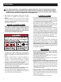 4
4
-
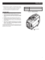 5
5
-
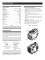 6
6
-
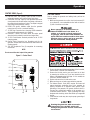 7
7
-
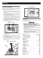 8
8
-
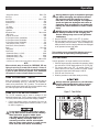 9
9
-
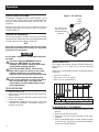 10
10
-
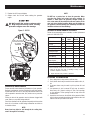 11
11
-
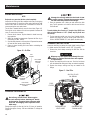 12
12
-
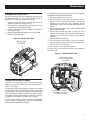 13
13
-
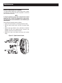 14
14
-
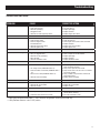 15
15
-
 16
16
-
 17
17
-
 18
18
-
 19
19
-
 20
20
-
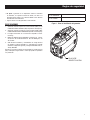 21
21
-
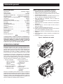 22
22
-
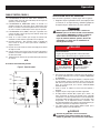 23
23
-
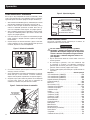 24
24
-
 25
25
-
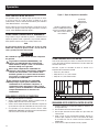 26
26
-
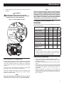 27
27
-
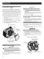 28
28
-
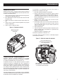 29
29
-
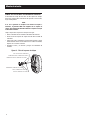 30
30
-
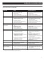 31
31
-
 32
32


Generac iX1400 G0058420 Manual de usuario
- Categoría
- Generadores de poder
- Tipo
- Manual de usuario
en otros idiomas
- English: Generac iX1400 G0058420 User manual