Baumer ITD 01 A 4 Y 4 Installation and Operating Instructions
- Tipo
- Installation and Operating Instructions

ITD 01
DIN EN 61340-5-1
DIN EN 61340-5-2
ITD 01 B14 500 T NI KR1 S 4
500 ppr TTL 5 VDC
Item: 11099481 Serial: 000000000000
www.baumer.com Made in Germany
A: GN B: GY Z: BN
A inv: YE B inv: PK Z inv: WH
+UB: RD GND: BU
Case:Screen
D384
DE Montageanleitung
GB Assembly Instructions
FR Notice de montage
IT Istruzioni di montaggio
ES Instrucciones de montaje
Inkrementale Drehgeber
Incremental encoder
Codeur incrémental
Encoder incrementale
Encoder incremental
Technische Daten/Technical data/Caractéristiques techniques/Dati tecnici
Especicaciones técnicas
Betriebsspannung/Voltage supply/Alimentation/Tensione d’esercizio
Tensión de servicio
5 VDC ±5 %, TTL
8...30 VDC, HTL/Push pull
5
¡
Max. 8 N Max. 5 N R = ≥28,5 mm ø = 5,7 mm
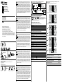
Anschlussbelegung/Terminal assignment/Raccordement
Assegnazione dei connettori/ Patillaje del conector
Beispiel/Example/Exemple/Esempio/ Ejemplo
BX-Signale/BX-signals/Signaux BX/Segnali BX/Señales BX
grün | green (gn) A
gelb | yellow (yl) B
braun | brown (bn) UB
weiss | white (wh) GND
transparent Schirm, Gehäuse/shielding, housing
NX-Signale/NX-signals/Signaux NX/Segnali NX/Señales NX
grün | green (gn) A
gelb | yellow (yl) B
grau | grey (gy) Z
braun | brown (bn) UB
weiss | white (wh) GND
transparent Schirm, Gehäuse/shielding, housing
BI-Signale/BI-signals/Signaux BI/Segnali BI/Señales BI
grün | green (gn) A
gelb | yellow (yl) A
grau | grey (gy) B
rosa | pink (pk) B
rot | red (rd) UB
blau | blue (bu) GND
transparent Schirm, Gehäuse/shielding, housing
NI-Signale/NI-signals/Signaux NI/Segnali NI/Señales NI
grün | green (gn) A
gelb | yellow (yl) A
grau | grey (gy) B
rosa | pink (pk) B
braun | brown (bn) Z
weiss | white (wh) Z
rot | red (rd) UB
blau | blue (bu) GND
transparent Schirm, Gehäuse/shielding, housing
Ausgangssignale/Output signals/Signaux de sortie/Segnali in uscita
Señales de salida
BX-Signale/BX-signals/Signaux BX/Segnali BX/Señales BX
NX-Signale/NX-signals/Signaux NX/Segnali NX/Señales NX
A
B
N
90°
A
B
90°
A
A
B
B
BI-Signale/BI-signals/Signaux BI/Segnali BI/Señales BI
NI-Signale/NI-signals/Signaux NI/Segnali NI/Señales NI
90°
A
A
B
B
N
N
90°
90°
Schaltpegel/Trigger level/Niveaux électriques//Livello impostato/Nivel de ruido
Ausgänge/Outputs/Sorties/Uscite/Salidas TTL
Ausgangspegel/Output level/Niveau de sortie/ High ≥2,4 V
Livello di uscita/Nivel de salida Low ≥0,5 V
Belastung/Load/Charge/Sollecitazione/Carga ≤30 mA
Ausgänge/Outputs/Sorties/Uscite/Salidas HTL/Push pull
Ausgangspegel/Output level/Niveau de sortie/ High ≥UB -3 V
Livello di uscita/Nivel de salida Low ≥1,5 V
Belastung/Load/Charge/Sollecitazione/Carga ≤30 mA
Schirmung am Gehäuse/Shielding on housing/Blindage sur boîtier
Schermatura del corpo encoder/Blindaje en la carcasa
Störquellen
Noise sources
Sources parasites
Origine del disturbo
Fuentes de interferencias
>200 mm
≤100 m
>100 mm>100 mm
DE
Achtung: Anleitung unbedingt vor Inbetriebnahme lesen. Einbau und Mon-
tage sind von einer Fachkraft für Elektrik und Feinmechanik vorzunehmen.
Betriebsanleitung des Maschinenherstellers sowie örtliche Sicherheitsvor-
schriften beachten. Inbetriebnahme nur an einem CE-konformen Netzteil
gemäss EN 61000-6-2. Der elektrische Anschluss darf unter Spannung nicht
verbunden oder gelöst werden. Der Antrieb darf während der Montage nicht in
Betrieb gesetzt werden. Drehgeber nicht öffnen, mechanisch oder elektrisch
verändern. Drehgeber nur innerhalb der im Datenblatt angegebenen Grenz-
werte betreiben. Eine Gefährdung von Personen, eine Beschädigung der An-
lage oder von Betriebseinrichtungen durch den Ausfall oder Fehlfunktion des
Drehgebers muss durch geeignete Sicherheitsmassnahmen ausgeschlossen
werden. Die Montageanleitung ist eine Ergänzung zu weiteren Dokumentati-
onen. Drehgeber dienen der Erfassung von Positionen und Drehzahlen. Sie
dürfen nur zu diesem Zweck verwendet werden.
GB
Note: It is imperative to read the user manual diligently prior to commissio-
ning. Mounting and commissioning is to be conducted by a specialist in elec-
trical equipment and precision mechanics under compliance with local safety
regulations. Commissioning only with CE compliant power supply according
to EN 61000-6-2. Observe also the operating instructions of the machine
manufacturer and all safety precautions requested by the respective national
authorities. Never plug or unplug the electrical connector while the device is
live. The drive must not be put into operation during installation. Do not open
and modify the encoder mechanically or electrically. Operate the encoder only
within the operating range specied in the data sheet. Make sure that a failure
or malfunction of the encoder does not lead to injuries of persons or damage
of equipment by appropriate safety measures. These assembly instructions
are intended as supplements to additional documentation. Intended purpose
of the encoder is to detect positions and engine speed.
Encoders may only be used for the stated purpose.
FR
Attention: Lire impérativement la notice avant la mise en service. L’installa-
tion et le montage doivent être effectués par un spécialiste de l’électricité et
de la mécanique de précision. Respecter le mode d’emploi du fabricant des
machines ainsi que les directives de sécurité locales. A n’utiliser qu’avec une
alimentation CE conforme EN 61000-6-2. Ne pas effectuer les raccordements
électriques ou les débrancher lorsque l’appareil est sous tension. Ne pas faire
fonctionner l’entraînement pendant le montage. Ne pas ouvrir le codeur, ni
effectuer de modications mécaniques ou électriques sur celui-ci. En ce qui
concerne le fonctionnement du codeur, respecter impérativement les valeurs
limites indiquées sur la che technique. An d’exclure toute panne ou tout
dysfonctionnement du codeur qui pourraient porter atteinte aux personnes,
endommager l’installation ou les équipements d’exploitation, il convient de
prendre des mesures de sécurité appropriées. La notice de montage com-
plète d’autres documents. Les codeurs servent à déterminer des positions et
des vitesses. Ils ne doivent être utilisés qu’à cette n.
IT
Attenzione: leggere assolutamente le istruzioni prima della messa in funzione.
L’installazione e il montaggio devono essere eseguiti da personale specia-
lizzato in elettrotecnica e meccanica di precisione. Osservare le istruzioni
per l’uso del produttore della macchina e le norme di sicurezza vigenti. Da
utilizzare solo con alimentatori conformi alla normativa CE EN 61000-6-2. Non
collegare o staccare il connettore elettrico sotto tensione. La trasmissione non
deve essere messa in funzione durante il montaggio. Non aprire l’encoder e
non apportare modiche meccaniche o elettriche. Far funzionare l’encoder so-
lo entro la gamma di valori indicati nella scheda tecnica. Evitare con adeguate
misure di sicurezza che guasti o funzionamenti scorretti dell’encoder mettano
in pericolo l’incolumità delle persone e danneggino l’impianto o le installazioni.
Le istruzioni di montaggio integrano le ulteriori documentazioni. Gli encoder
servono per il rilevamento delle posizioni e delle velocità. Devono essere uti-
lizzati solo per tali scopi.
ES
Atención: léase las instrucciones antes de realizar la puesta en servicio. La
instalación y el montaje deben ser efectuados por un técnico electricista y me-
cánico de precisión. Obsérvese el manual de instrucciones del fabricante de
la máquina y las normas de seguridad locales. Puesto en marcha solamente
con una fuente de alimentación compatible CE según EN 61000-6-2. La co-
nexión eléctrica no puede ser enchufada ni desenchufada bajo tensión. No se
puede poner en marcha el accionamiento durante el montaje. No está permiti-
do abrir el encoder ni realizar cambios mecánicos o eléctricos. Solo está per-
mitido operar el encoder dentro de los valores límite indicados en la hoja de
datos. Es preciso tomar las medidas de seguridad adecuadas para evitar todo
riesgo para las personas o daños en la instalación o en otros equipos debido
al fallo o al mal funcionamiento del encoder. El manual de instrucciones es un
complemento a otros documentos. Los encoder sirven para registrar posicio-
nes y revoluciones. Solo pueden ser utilizados para esa nalidad.
Baumer Thalheim GmbH & Co. KG
Hessenring 17 · DE-37269 Eschwege
Phone +49 5651 9239-0 · Fax +49 5651 9239-80
[email protected] · www.baumer.com
06-17 · 11117998 · Version 03 · Printed in Germany
Irrtum sowie Änderungen in Technik und Design vorbehalten.
Subject to modication in technic and design. Errors and omissions excepted.
Sous réserve de modications et d’erreur dans la technique et le design.
Salvo errori ed omissioni. Con riserva di modiche tecniche e di design.
Salvo errores y omisiones. Reservado el derecho a introducir modicaciones
técnicas y de diseño.
Siehe Typenschild/See product label
Voir plaque signalétique/Nota targhetta
Ver placa de características

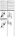
Montage über anschseitige Gewindebohrungen/Mounting via threaded holes
on the ange side/Montage par trous taraudés côté bride/ Montaggio con cam-
pana/Montaje mediante oricios roscados en el lado de la brida
Montage mit Befestigungsexzenter (kein Zubehör)/Mounting with mounting
clamps (no accessories)/Montage à l‘aide d‘une excentrique de xation (aucun
accessoires)/Montaggio con eccentrici di ssaggio (senza accessori)/Montaje
o con excéntricos de jación (sin accesorios)
Montage mit Statorkupplung/Mounting with stator coupling/Montage avec
ressort anti-rotation/ Montaggio con molla elastica/Montaje con acoplamiento
de estator
3.
1.
2.
3 x M2
(1.0 Nm)
3.
2.
1.
2.
3 x M2
1.
0.25 Nm
M1.6
3.
≥4
ø4 - ø6H7
≥8
≤12
ø4 - ø6g6
M
2
Drehgeber mit einseitig offener Hohlwelle/Encoder with blind hollow shaft/
Codeur avec axe creux non traversant/ Encoder con albero cieco/Encoder con
eje hueco abierto por un lado
Vor Montage des Drehgebers, Klemmring vollständig öffnen. Fremdkörper sind in
ausreichendem Abstand zur Statorkupplung zu halten. Die Statorkupplung darf aus-
ser an den Befestigungspunkten des Drehgebers und der Maschine nicht anstehen.
Open clamping ring completely before mounting the encoder. Foreign objects must
be kept at a sufcient distance from the stator coupling. The stator coupling is not
allowed to have any contact to the encoder or the machine except at the mounting
points.
Avant le montage du codeur, ouvrir complètement la bague de serrage. Maintenir les
corps étrangers à distance sufsante du ressort anti-rotation. Le ressort anti-rotation
ne doit pas se trouver en dehors des points de xation du codeur et de la machine.
Prima del montaggio dell‘encoder, aprire completamente l‘anello di bloccaggio. Corpi
estranei vanno tenuti a debita distanza dal giunto di accoppiamento dello statore.
Il giunto dello statore non deve sporgere dai punti di ssaggio dell‘encoder e della
macchina.
Antes de montar el encoder, abrir completamente el anillo de apriete Debe man-
tenerse los cuerpos extraños a una distancia suciente del acoplamiento del estator.
El acoplamiento del estator no puede estar en contacto a excepción de en los puntos
de jación del encoder y de la máquina.
Kundenseitige Welle/Customer‘s shaft/ Arbre côté client/Albero lato cliente/
Eje por parte del cliente
Drehgeber mit Servoansch/Encoder with synchro ange/Codeur avec bride synchro/
Encoder con servoangia/Encoder con servobrida
Keine starre Verbindung von Drehgeberwelle und Antriebswelle vornehmen. Antriebs-
und Drehgeberwelle über eine geeignete Kupplung verbinden. Auf korrekten Anbau
und störungsfreien Betrieb ist zu achten. Fremdkörper sind in ausreichendem Abstand
zur Kupplung zu halten.
Do not connect encoder shaft and drive shaft rigidly. Connect drive and encoder shaft
with a suitable coupling. Ensure correct installation and trouble-free operation. Foreign
objects must be kept at a sufcient distance from the coupling.
Ne pas raccorder l’arbre du codeur et l’arbre d’entraînement de manière rigide.
Raccorder les arbres d’entraînement et du codeur au moyen d’un accouplement ap-
proprié. Veiller à une installation correcte et à un fonctionnement parfait. Maintenir les
corps étrangers à distance sufsante de l’accouplement.
Non eseguire alcun collegamento rigido di albero encoder e albero motore. Albero
motore e albero encoder vanno collegati tramite apposito giunto di accoppiamento.
Fare attenzione che il montaggio sia corretto e il funzionamento senza interferenze.
Corpi estranei vanno tenuti a debita distanza dal giunto di accoppiamento.
No realizar una unión rígida del eje del encoder y el árbol motor. Unir el árbol motor y
el eje del encoder mediante un acoplamiento apropiado. Debe observarse un correcto
montaje y funcionamiento sin fallos. Debe mantenerse los cuerpos extraños a una
distancia suciente del acoplamiento.
Transcripción de documentos
DE DE GB FR IT ES Montageanleitung Assembly Instructions Notice de montage Istruzioni di montaggio Instrucciones de montaje ITD 01 Achtung: Anleitung unbedingt vor Inbetriebnahme lesen. Einbau und Montage sind von einer Fachkraft für Elektrik und Feinmechanik vorzunehmen. Betriebsanleitung des Maschinenherstellers sowie örtliche Sicherheitsvorschriften beachten. Inbetriebnahme nur an einem CE-konformen Netzteil gemäss EN 61000-6-2. Der elektrische Anschluss darf unter Spannung nicht verbunden oder gelöst werden. Der Antrieb darf während der Montage nicht in Betrieb gesetzt werden. Drehgeber nicht öffnen, mechanisch oder elektrisch verändern. Drehgeber nur innerhalb der im Datenblatt angegebenen Grenzwerte betreiben. Eine Gefährdung von Personen, eine Beschädigung der Anlage oder von Betriebseinrichtungen durch den Ausfall oder Fehlfunktion des Drehgebers muss durch geeignete Sicherheitsmassnahmen ausgeschlossen werden. Die Montageanleitung ist eine Ergänzung zu weiteren Dokumentationen. Drehgeber dienen der Erfassung von Positionen und Drehzahlen. Sie dürfen nur zu diesem Zweck verwendet werden. Schirmung am Gehäuse/Shielding on housing/Blindage sur boîtier Schermatura del corpo encoder/Blindaje en la carcasa Störquellen Noise sources Sources parasites Origine del disturbo Fuentes de interferencias >100 mm >100 mm >200 mm GB Baumer Thalheim GmbH & Co. KG Hessenring 17 · DE-37269 Eschwege Phone +49 5651 9239-0 · Fax +49 5651 9239-80 [email protected] · www.baumer.com 06-17 · 11117998 · Version 03 · Printed in Germany Irrtum sowie Änderungen in Technik und Design vorbehalten. Subject to modification in technic and design. Errors and omissions excepted. Sous réserve de modifications et d’erreur dans la technique et le design. Salvo errori ed omissioni. Con riserva di modifiche tecniche e di design. Salvo errores y omisiones. Reservado el derecho a introducir modificaciones técnicas y de diseño. Note: It is imperative to read the user manual diligently prior to commissioning. Mounting and commissioning is to be conducted by a specialist in electrical equipment and precision mechanics under compliance with local safety regulations. Commissioning only with CE compliant power supply according to EN 61000-6-2. Observe also the operating instructions of the machine manufacturer and all safety precautions requested by the respective national authorities. Never plug or unplug the electrical connector while the device is live. The drive must not be put into operation during installation. Do not open and modify the encoder mechanically or electrically. Operate the encoder only within the operating range specified in the data sheet. Make sure that a failure or malfunction of the encoder does not lead to injuries of persons or damage of equipment by appropriate safety measures. These assembly instructions are intended as supplements to additional documentation. Intended purpose of the encoder is to detect positions and engine speed. Encoders may only be used for the stated purpose. ≤100 m FR D384 ITD 01 B14 500 T NI KR1 S 4 500 ppr TTL 5 VDC Item: 11099481 Serial: 000000000000 www.baumer.com Made in Germany A: GN B: GY Z: BN A inv: YE B inv: PK Z inv: WH +UB: RD GND: BU Case:Screen Siehe Typenschild/See product label Voir plaque signalétique/Nota targhetta Ver placa de características DIN EN 61340-5-1 DIN EN 61340-5-2 IT Technische Daten/Technical data/Caractéristiques techniques/Dati tecnici Especificaciones técnicas Betriebsspannung/Voltage supply/Alimentation/Tensione d’esercizio Tensión de servicio 5 VDC ±5 %, TTL 8...30 VDC, HTL/Push pull 5 Max. 8 N Max. 5 N R = ≥28,5 mm ¡ ø = 5,7 mm ES Atención: léase las instrucciones antes de realizar la puesta en servicio. La instalación y el montaje deben ser efectuados por un técnico electricista y mecánico de precisión. Obsérvese el manual de instrucciones del fabricante de la máquina y las normas de seguridad locales. Puesto en marcha solamente con una fuente de alimentación compatible CE según EN 61000-6-2. La conexión eléctrica no puede ser enchufada ni desenchufada bajo tensión. No se puede poner en marcha el accionamiento durante el montaje. No está permitido abrir el encoder ni realizar cambios mecánicos o eléctricos. Solo está permitido operar el encoder dentro de los valores límite indicados en la hoja de datos. Es preciso tomar las medidas de seguridad adecuadas para evitar todo riesgo para las personas o daños en la instalación o en otros equipos debido al fallo o al mal funcionamiento del encoder. El manual de instrucciones es un complemento a otros documentos. Los encoder sirven para registrar posiciones y revoluciones. Solo pueden ser utilizados para esa finalidad. B A B 90° N Beispiel/Example/Exemple/Esempio/ Ejemplo BX-Signale/BX-signals/Signaux BX/Segnali BX/Señales BX grün | green (gn) A gelb | yellow (yl) B braun | brown (bn) UB weiss | white (wh) GND transparent Schirm, Gehäuse/shielding, housing grün | green (gn) A gelb | yellow (yl) B grau | grey (gy) Z braun | brown (bn) UB weiss | white (wh) GND transparent Schirm, Gehäuse/shielding, housing BI-Signale/BI-signals/Signaux BI/Segnali BI/Señales BI grün | green (gn) A gelb | yellow (yl) A grau | grey (gy) B rosa | pink (pk) B rot | red (rd) UB blau | blue (bu) GND transparent Schirm, Gehäuse/shielding, housing NI-Signale/NI-signals/Signaux NI/Segnali NI/Señales NI Attenzione: leggere assolutamente le istruzioni prima della messa in funzione. L’installazione e il montaggio devono essere eseguiti da personale specializzato in elettrotecnica e meccanica di precisione. Osservare le istruzioni per l’uso del produttore della macchina e le norme di sicurezza vigenti. Da utilizzare solo con alimentatori conformi alla normativa CE EN 61000-6-2. Non collegare o staccare il connettore elettrico sotto tensione. La trasmissione non deve essere messa in funzione durante il montaggio. Non aprire l’encoder e non apportare modifiche meccaniche o elettriche. Far funzionare l’encoder solo entro la gamma di valori indicati nella scheda tecnica. Evitare con adeguate misure di sicurezza che guasti o funzionamenti scorretti dell’encoder mettano in pericolo l’incolumità delle persone e danneggino l’impianto o le installazioni. Le istruzioni di montaggio integrano le ulteriori documentazioni. Gli encoder servono per il rilevamento delle posizioni e delle velocità. Devono essere utilizzati solo per tali scopi. A NX-Signale/NX-signals/Signaux NX/Segnali NX/Señales NX NX-Signale/NX-signals/Signaux NX/Segnali NX/Señales NX Attention: Lire impérativement la notice avant la mise en service. L’installation et le montage doivent être effectués par un spécialiste de l’électricité et de la mécanique de précision. Respecter le mode d’emploi du fabricant des machines ainsi que les directives de sécurité locales. A n’utiliser qu’avec une alimentation CE conforme EN 61000-6-2. Ne pas effectuer les raccordements électriques ou les débrancher lorsque l’appareil est sous tension. Ne pas faire fonctionner l’entraînement pendant le montage. Ne pas ouvrir le codeur, ni effectuer de modifications mécaniques ou électriques sur celui-ci. En ce qui concerne le fonctionnement du codeur, respecter impérativement les valeurs limites indiquées sur la fiche technique. Afin d’exclure toute panne ou tout dysfonctionnement du codeur qui pourraient porter atteinte aux personnes, endommager l’installation ou les équipements d’exploitation, il convient de prendre des mesures de sécurité appropriées. La notice de montage complète d’autres documents. Les codeurs servent à déterminer des positions et des vitesses. Ils ne doivent être utilisés qu’à cette fin. BX-Signale/BX-signals/Signaux BX/Segnali BX/Señales BX 90° Anschlussbelegung/Terminal assignment/Raccordement Assegnazione dei connettori/ Patillaje del conector Inkrementale Drehgeber Incremental encoder Codeur incrémental Encoder incrementale Encoder incremental Ausgangssignale/Output signals/Signaux de sortie/Segnali in uscita Señales de salida grün | green (gn) A gelb | yellow (yl) A grau | grey (gy) B rosa | pink (pk) B braun | brown (bn) Z weiss | white (wh) Z rot | red (rd) UB blau | blue (bu) GND transparent Schirm, Gehäuse/shielding, housing BI-Signale/BI-signals/Signaux BI/Segnali BI/Señales BI A A B 90° B NI-Signale/NI-signals/Signaux NI/Segnali NI/Señales NI A A B B 90° N N 90° Schaltpegel/Trigger level/Niveaux électriques//Livello impostato/Nivel de ruido Ausgänge/Outputs/Sorties/Uscite/Salidas TTL Ausgangspegel/Output level/Niveau de sortie/ Livello di uscita/Nivel de salida High ≥2,4 V Low ≥0,5 V Belastung/Load/Charge/Sollecitazione/Carga ≤30 mA Ausgänge/Outputs/Sorties/Uscite/Salidas HTL/Push pull Ausgangspegel/Output level/Niveau de sortie/ Livello di uscita/Nivel de salida High ≥UB -3 V Low ≥1,5 V Belastung/Load/Charge/Sollecitazione/Carga ≤30 mA Drehgeber mit Servoflansch/Encoder with synchro flange/Codeur avec bride synchro/ Encoder con servoflangia/Encoder con servobrida Keine starre Verbindung von Drehgeberwelle und Antriebswelle vornehmen. Antriebsund Drehgeberwelle über eine geeignete Kupplung verbinden. Auf korrekten Anbau und störungsfreien Betrieb ist zu achten. Fremdkörper sind in ausreichendem Abstand zur Kupplung zu halten. Drehgeber mit einseitig offener Hohlwelle/Encoder with blind hollow shaft/ Codeur avec axe creux non traversant/ Encoder con albero cieco/Encoder con eje hueco abierto por un lado Vor Montage des Drehgebers, Klemmring vollständig öffnen. Fremdkörper sind in ausreichendem Abstand zur Statorkupplung zu halten. Die Statorkupplung darf ausser an den Befestigungspunkten des Drehgebers und der Maschine nicht anstehen. Do not connect encoder shaft and drive shaft rigidly. Connect drive and encoder shaft with a suitable coupling. Ensure correct installation and trouble-free operation. Foreign objects must be kept at a sufficient distance from the coupling. Open clamping ring completely before mounting the encoder. Foreign objects must be kept at a sufficient distance from the stator coupling. The stator coupling is not allowed to have any contact to the encoder or the machine except at the mounting points. Ne pas raccorder l’arbre du codeur et l’arbre d’entraînement de manière rigide. Raccorder les arbres d’entraînement et du codeur au moyen d’un accouplement approprié. Veiller à une installation correcte et à un fonctionnement parfait. Maintenir les corps étrangers à distance suffisante de l’accouplement. Avant le montage du codeur, ouvrir complètement la bague de serrage. Maintenir les corps étrangers à distance suffisante du ressort anti-rotation. Le ressort anti-rotation ne doit pas se trouver en dehors des points de fixation du codeur et de la machine. Non eseguire alcun collegamento rigido di albero encoder e albero motore. Albero motore e albero encoder vanno collegati tramite apposito giunto di accoppiamento. Fare attenzione che il montaggio sia corretto e il funzionamento senza interferenze. Corpi estranei vanno tenuti a debita distanza dal giunto di accoppiamento. Prima del montaggio dell‘encoder, aprire completamente l‘anello di bloccaggio. Corpi estranei vanno tenuti a debita distanza dal giunto di accoppiamento dello statore. Il giunto dello statore non deve sporgere dai punti di fissaggio dell‘encoder e della macchina. No realizar una unión rígida del eje del encoder y el árbol motor. Unir el árbol motor y el eje del encoder mediante un acoplamiento apropiado. Debe observarse un correcto montaje y funcionamiento sin fallos. Debe mantenerse los cuerpos extraños a una distancia suficiente del acoplamiento. Antes de montar el encoder, abrir completamente el anillo de apriete Debe mantenerse los cuerpos extraños a una distancia suficiente del acoplamiento del estator. El acoplamiento del estator no puede estar en contacto a excepción de en los puntos de fijación del encoder y de la máquina. Montage über flanschseitige Gewindebohrungen/Mounting via threaded holes on the flange side/Montage par trous taraudés côté bride/ Montaggio con campana/Montaje mediante orificios roscados en el lado de la brida Montage mit Statorkupplung/Mounting with stator coupling/Montage avec ressort anti-rotation/ Montaggio con molla elastica/Montaje con acoplamiento de estator 1. 3. 0.25 Nm M1.6 1. 3. 2. 3 x M2 2. ≥8 ≤12 3. ø4 - ø6H7 1. 3 x M2 (1.0 Nm) ≥4 ø4 - ø6g6 2. Kundenseitige Welle/Customer‘s shaft/ Arbre côté client/Albero lato cliente/ Eje por parte del cliente M2 Montage mit Befestigungsexzenter (kein Zubehör)/Mounting with mounting clamps (no accessories)/Montage à l‘aide d‘une excentrique de fixation (aucun accessoires)/Montaggio con eccentrici di fissaggio (senza accessori)/Montaje o con excéntricos de fijación (sin accesorios)-
 1
1
-
 2
2


Baumer ITD 01 A 4 Y 4 Installation and Operating Instructions
- Tipo
- Installation and Operating Instructions
en otros idiomas
- français: Baumer ITD 01 A 4 Y 4
- italiano: Baumer ITD 01 A 4 Y 4
- English: Baumer ITD 01 A 4 Y 4
- Deutsch: Baumer ITD 01 A 4 Y 4
Artículos relacionados
-
Baumer EIL580-SY Installation and Operating Instructions
-
Baumer EIL580P-SQ Installation and Operating Instructions
-
-
Baumer EAM360-K - CANopen® Installation and Operating Instructions
-
-
-
-
-