
XS-AW8
5-019-996-51(1)
ACTIVE SUBWOOFER
Operating Instructions
GB
Manual de instrucciones
ES
TH

2GB
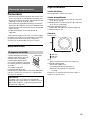
The nameplate indicating operating voltage, etc., is
located on the bottom of the subwoofer.
If you have any questions or problems concerning
your unit that are not covered in this manual,
consult your nearest Sony dealer.
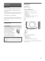
Features
•Easy installation
• 20 cm (8 in) subwoofer
• Power output of 160 W (max)/75 W (RMS) with
supply voltage of 14.4 V
• Adoption of a high rigidity aluminum die-cast box
For your safety, be sure to install this unit at a
mounting location that will not interfere with any
driving operations.
For details, see “Connection and Installation”
(page 5).

3GB
Table of Contents
Features . . . . . . . . . . . . . . . . . . . . . . . . . . . . . . . . . . 2
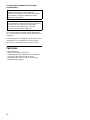
Guide to Parts and Controls
Subwoofer . . . . . . . . . . . . . . . . . . . . . . . . . . . . . . . . 4
Remote Gain Controller . . . . . . . . . . . . . . . . . . . . . . 4
Connection and Installation
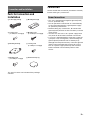
Parts for Connection and Installation . . . . . . . . . . . 5
Connection . . . . . . . . . . . . . . . . . . . . . . . . . . . . . . . . 5
Installation . . . . . . . . . . . . . . . . . . . . . . . . . . . . . . . . 9
Additional Information
Precautions. . . . . . . . . . . . . . . . . . . . . . . . . . . . . . . . 11
Maintenance. . . . . . . . . . . . . . . . . . . . . . . . . . . . . . . 11
Specifications . . . . . . . . . . . . . . . . . . . . . . . . . . . . . . 11
Troubleshooting . . . . . . . . . . . . . . . . . . . . . . . . . . . . 12

4GB
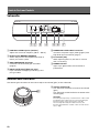
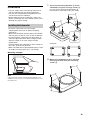
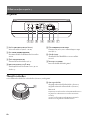
Subwoofer
LOW PASS FILTER adjustor (LP Filter)
Adjusts the crossover frequency (50 Hz – 150 Hz).
PHASE select (NORMAL/REVERSE)
Selects the phase of the reproduced sound to
match your audio system.
GAIN CONTROLLER connector
Connector for the remote gain controller
(page 4).
INPUT CH1(R)/CH2(L) (RCA pin-type)
Input connector for Right (R) and Left (L) RCA
pin-type cable.
POWER/HIGH LEVEL INPUT connector
Connector for power supply leads (page 6) and
high level input connection (page 7).
Fuse holder (15A)
When replacing the fuse, be sure to use one
with a 15 A rating.
POWER indicator
Lights up in green when the subwoofer is
powered on.
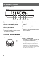
Remote Gain Controller
The remote gain controller can be used to adjust the volume (gain) of the subwoofer.
Volume control knob
Turn the knob clockwise to increase the volume
(gain).
Turn the knob counterclockwise to decrease the
volume (gain).
CAUTION
Excessive gain input may cause distortion of the sound
produced by the subwoofer. Do not increase the gain
level excessively on the remote gain controller.
The sound produced by the subwoofer may also
become distorted if the volume of the car audio unit is
set too high.
Guide to Parts and Controls
ȩȪ ȫ ȭȮ ȯȬ
Ȱ

5GB
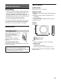
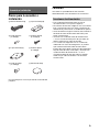
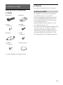
Parts for Connection and
Installation
This parts list does not include all the package
contents.
Connection
Please read all the connection procedures carefully
before making any connections.
• This unit is designed for negative ground (earth)
12 V DC operation only.
• Do not operate the subwoofer on a weak battery
as the subwoofer requires a good power supply
for optimum performance.
• Before making any connections, disconnect the
ground (earth) terminal of the car battery to avoid
short circuits.
• Connect this unit to the +12 V power supply lead
only after all other leads have been connected.
• If your car is equipped with a computer system for
a purpose such as navigation, disconnecting the
ground (earth) lead from the car battery may
damage the computer memory. Leave the ground
(earth) lead connected and connect this unit to
the +12 V power supply lead only after all other
leads have been connected to prevent short
circuits.
Connection and Installation
Power supply leads (1) Mounting bracket (4)
Securing screw
(5 × 8 mm (
7
/32 ×
11
/32 in)) (4)
Mounting screw
(5 × 20 mm (
7
/32 ×
13
/16 in)) (4)
Mounting bracket (1) Securing screw
(2 × 5 mm (
3
/32 ×
7
/32 in)) (2)
Mounting screw
(3 × 12 mm (
1
/8 ×
1
/2 in)) (2)
Double-sided tape (1)
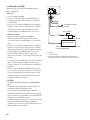
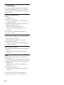
Power Connections

6GB
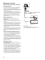
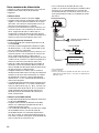
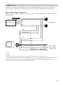
Making power connections
Connect the power supply leads to the POWER/
HIGH LEVEL INPUT connector on the subwoofer.
Ground (earth) lead
• The ground (earth) lead (GND) is the black lead.
• Be sure to connect the ground (earth) lead
securely to a bare metal ground (earth) point on
the car chassis. A loose connection may cause the
unit to malfunction.
• During full-power operation, a current close to
15 A will run through the system. Therefore, make
sure the wires to be connected to the ground
(earth) lead of this unit are at least 14-Gauge
(AWG-14) or have a sectional area of more than
2 mm² (
3
/32 in²).
Battery extension lead
• The battery extension lead (BATTERY) is the
yellow lead.
• Connect the battery extension lead to the car
battery’s +12 V power supply lead with a 15 A fuse
attached.
• During full-power operation, a current close to
15 A will run through the system. Therefore, make
sure the wires to be connected to the battery
extension lead of this unit are at least 14-Gauge
(AWG-14) or have a sectional area of more than
2 mm² (
3
/32 in²).
• All power wires connected to the positive battery
post should be fused within 450 mm (17
3
/4 in) of
the battery post before they pass through any
metal.
• Make sure the wires connecting from the car
battery to the metal ground (earth) point on the
car chassis are of a wire gauge at least equal to
that of the +12 V power supply lead connected
from the battery to the subwoofer.
• If the amperage rating of the fuse used on the
+12 V power supply lead of your car battery is less
than 15 A (e.g., 10 A), connect to a car system with
at least 15 A, or connect the battery extension lead
directly to the positive post of the car battery to
avoid short circuits.
Remote turn-on lead
• The remote turn-on lead (REMOTE TURN-ON) is
the blue/white lead.
• Be sure to connect the remote turn-on lead to the
remote turn-on output of the car audio unit.
• If your car audio unit does not have a remote turn-
on output, connect the remote turn-on lead to the
ACC power supply of your car. Power will be
supplied to this lead when the ignition switch of
your car is set to the ACC position.
• With high level input connection (page 7), the
subwoofer can also be activated without the need
for a remote turn-on connection. However, this
function is not guaranteed for all car audio units.
*1 Not supplied
*2 Ground (earth) to chassis.
*3 For car audio unit without a remote turn-on output,
connect to the ACC power supply of the car.
Black
to a metal ground (earth) point
on the chassis
Ye l l o w
Blue/White
Fuse (15 A)
+12 V car battery
Car audio*
1
to the remote turn-on output*
3
of the car audio
*
1
*
2
less than 450 mm (17
3
/4 in)

7GB
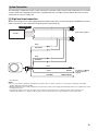
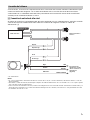
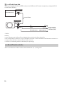
The following is a depiction of the system connections typically used to connect the subwoofer to a car audio
system. Refer to the operating instructions supplied with your car audio for more details about the system
connection for your car audio unit.
High level input connection
When connecting to a car audio equipped with speaker output only, connect through the POWER/HIGH LEVEL
INPUT connector on the subwoofer using the power supply leads .
*Not supplied
Notes
• Do not connect the terminal of the speaker system to the car chassis, and do not connect the terminal of the right
speaker with that of the left speaker.
• When installing the input cables, keep them away from the yellow power supply lead. Running them close together may result
in interference noise.
• For high level input connection, the subwoofer operates automatically upon receiving an audio signal and turns off
automatically if there is no signal for 30 seconds. However, this function is not guaranteed for all car audio units.
System Connection
SPEAKER OUT
GND
BATTERY
REMOTE TURN-ON
Car audio*
Front or Rear speakers*
Purple
Green
Purple/Black
Black
Yel low
Blue/White
Green/Black
For details, see “Making
power connections”
(page 6).
*
*
*
*
*
*
*
*

8GB
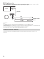
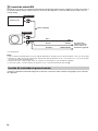
RCA input connection
When connecting to a car audio equipped with RCA output terminals, connect through the INPUT CH1(R)/
CH2(L) connector on the subwoofer using a RCA pin-type cable (not supplied).
*Not supplied
Notes
• For RCA input connection, connect the yellow power supply lead as close to the car battery as possible.
• When installing the input cables, keep them away from the yellow power supply lead. Running them close together may result
in interference noise.
• Be sure to insulate any loose, unconnected leads with electrical tape for safe measure.
• If noise is present, connect the subwoofer with the high level input connection.
Connect the cable of the remote gain controller to the GAIN CONTROLLER connector (page 4) on the
subwoofer.
Remote Gain Controller Connection
RCA INPUT
RCA OUTPUT
GND
BATTERY
REMOTE TURN-ON
Car audio*
RCA pin cable*
Black
Ye l l ow
Blue/White
For details, see “Making
power connections”
(page 6).

9GB
Installation
• For your safety, select a mounting location that
will not interfere with any driving operations.
• Use only the supplied mounting hardware for a
safe and successful installation.
•Before drilling holes for installation, make sure
there is nothing on the floor and be careful not to
damage any pipe or wiring.
• Install the subwoofer in the passenger
compartment to ensure an optimal listening
experience.
• Mount the subwoofer where it does not interfere
with any parts of the car (such as the car battery).
• Do not install the subwoofer near the heater, in
areas that get exposed to direct sunlight, under
the floor carpet, or in areas subject to high
temperature.
• Avoid installing the subwoofer in areas subject to
dust, dirt, or excessive vibration.
•Make sure leads do not get trapped under a screw
or caught in moving parts (e.g., seat railing).
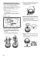
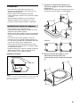
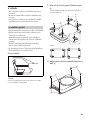
Mounting example
Note
If the mounting location in the mounting example is not
suitable for your car, choose another mounting location for
the subwoofer.
1 Secure the mounting brackets to the
subwoofer using the securing screws .
You can secure the mounting brackets
horizontally or vertically to suit your needs.
Examples:
2 Mount the subwoofer to your selected
mounting location with the mounting
screws .
Installing the Subwoofer

10GB
•Do not install the remote gain controller near the
heater, in areas that get exposed to direct
sunlight, or in areas subject to high temperature.
• Avoid installing the remote gain controller in areas
subject to dust, dirt, or moisture.
•Install the remote gain controller in a location
where:
– There is a flat surface.
– The controller does not interfere with the
driver’s movement.
– The controller does not hinder the operations of
the steering wheel, shift level, or the brake
pedal.
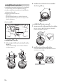
Mounting example
Installing using the mounting bracket
1
Secure the mounting bracket to the
remote gain controller using the securing
screws .
You can secure the mounting bracket
horizontally or vertically to suit your needs.
2 Mount the remote gain controller to your
selected mounting location with the
mounting screws .
Installing using the double-sided tape
1
Apply the double-sided tape to the base
of the remote gain controller.
Match the curve of the double-sided tape to
that of the remote gain controller as shown
below.
2 Mount the remote gain controller to a flat
surface.
Clean the surface of your selected mounting
location with a dry cloth before applying the
double-sided tape .
Installing the Remote Gain Controller

11GB
Precautions
•If your car is parked in direct sunlight and there is
a considerable rise in temperature inside the car,
allow the subwoofer to cool down before use.
• For safety, keep the volume of the subwoofer at a
moderate level that allows you to sufficiently hear
the sound of traffic outside the vehicle.
• Do not splash liquid onto the subwoofer.
If you have any questions or problems concerning
your unit that are not covered in this Operating
Instructions, consult your nearest Sony dealer.
Maintenance
When replacing the fuse, be sure
to use one matching the
amperage rating stated on the
original fuse.
If the fuse blows, check the
power connection and replace
the fuse.
If the fuse blows again after
replacement, there may be an
internal malfunction. If this happens, consult your
nearest Sony dealer.
Specifications
Speaker section
Woofer: 20 cm (8 in), cone type
Amplifier section
Maximum power output (supply voltage at 14.4 V):
160 W
Rated power output (supply voltage at 14.4 V):
75 W (RMS)
Power requirement:
12 V DC car battery (negative ground (earth))
Rated current: 8 A
General
Dimensions:
250 mm (9
7
/8 in)
344 mm (13
5
/8 in)
78 mm (3
1
/8 in)
Mass:
Approx. 4.9 kg (10 lb 13 oz) for subwoofer
Package contents:
Subwoofer (1)
Remote gain controller (1)
Parts for connection and installation (1 set)
Design and specifications are subject to change
without notice.
Additional Information
Fuse Replacement
Warning
Never use a fuse with an amperage rating
exceeding the one supplied with the subwoofer
as this could damage the subwoofer.
Fuse (15 A)
ɸ
ɹɺ

12GB
Troubleshooting
The following checklist will assist in the correction
of most of the problems you may encounter with
your unit. Please refer to the connection and
operating procedures before going through the
checklist below.
The POWER indicator does not light up.
The fuse is blown.
– Replace the fuse lead with a new one.
The ground (earth) lead is not securely
connected.
– Fasten the ground (earth) lead securely to a
bare metal ground (earth) point on the car
chassis.
The voltage going into the remote turn-on lead
(REMOTE TURN-ON) is too low.
– Turn on the car audio unit if it is not turned on.
– Use a relay if there are too many amplifiers
installed within the system.
Make sure the battery voltage is between 10.5 V –
16 V.
Noise can be heard from the alternator.
The battery extension leads are installed too
close to the RCA pin cables or the high level input
cables.
– Keep the leads away from the cables.
The ground (earth) lead is not securely
connected.
– Fasten the ground (earth) lead securely to a
bare metal ground (earth) point on the car
chassis.
The subwoofer sound is too soft.
The volume of the car audio unit and/or the
subwoofer is set too low.
– Increase the volume of the subwoofer and/or
the car audio unit.
There is no sound.
The PHASE select switch is not correctly set (i.e.,
has been set between the settings).
– Properly set the switch on the subwoofer to
either NORMAL or REVERSE.
The volume of the car audio unit and/or the
subwoofer has been set to minimum.
– Increase the volume of the subwoofer and/or
the car audio unit.
The subwoofer is not properly connected.
– Make sure all the subwoofer connections have
been made correctly.
If these solutions do not help improve the situation,
consult your nearest Sony dealer.


2ES
ALTAVOZ DE SUBGRAVES ACTIVO PARA
AUTOESTÉREO
La placa que indica el voltaje de funcionamiento,
etc., está situada en la parte inferior del altavoz de
subgraves.
Si tiene preguntas o problemas relacionados con la
unidad que no se contemplan en este manual,
consulte a su representante Sony más cercano.
Funciones
• Fácil instalación
•Altavoz de subgraves de 20 cm
• Salida de potencia de 160 W (máx)/75 W (RMS)
con tensión de suministro de cc 14,4 V
• Implementación de una carcasa de aluminio
fundido de gran rigidez
POR FAVOR LEA DETALLADAMENTE ESTE
MANUAL DE INSTRUCCIONES ANTES DE
CONECTAR Y OPERAR ESTE EQUIPO. RECUERDE
QUE UN MAL USO DE SU APARATO PODRÍA
ANULAR LA GARANTÍA.
Por motivos de seguridad, asegúrese de instalar
esta unidad en una ubicación de montaje que no
interfiera con las acciones de conducción.
Para obtener más información, consulte
“Conexión e instalación” (página 5).

3ES
Tabla de contenido
Funciones . . . . . . . . . . . . . . . . . . . . . . . . . . . . . . . . . 2
Guía para las partes y los controles
Altavoz de subgraves . . . . . . . . . . . . . . . . . . . . . . . 4
Controlador de ganancia remoto . . . . . . . . . . . . . . 4
Conexión e instalación
Piezas para la conexión e instalación. . . . . . . . . . . 5
Conexión . . . . . . . . . . . . . . . . . . . . . . . . . . . . . . . . . . 5
Instalación . . . . . . . . . . . . . . . . . . . . . . . . . . . . . . . . 9
Información complementaria
Precauciones . . . . . . . . . . . . . . . . . . . . . . . . . . . . . . 11
Mantenimiento. . . . . . . . . . . . . . . . . . . . . . . . . . . . . 11
Especificaciones . . . . . . . . . . . . . . . . . . . . . . . . . . . . 11
Solución de problemas . . . . . . . . . . . . . . . . . . . . . . 12
Glosario de términos . . . . . . . . . . . . . . . . . . . . . . . . 13

4ES
Altavoz de subgraves
Ajustador LOW PASS FILTER (filtro LP)
Ajusta la frecuencia de corte (50 Hz – 150 Hz).
Selección de PHASE (NORMAL/REVERSE)
Seleccione la fase del sonido reproducido para
que se adapte a su sistema de audio.
Conector GAIN CONTROLLER
Conector para el controlador de ganancia
remoto (página 4).
INPUT CH1(R)/CH2(L) (tipo clavija RCA)
Conector de entrada para el cable de tipo clavija
RCA derecho (R) e izquierdo (L).
Conector POWER/HIGH LEVEL INPUT
Conector para los cables de alimentación
(página 6) y la conexión de entrada de alto nivel
(página 7).
Soporte para el fusible (15A)
Al sustituir el fusible, procure utilizar uno con
una clasificación de 15 A
Indicador POWER
Se ilumina en color verde cuando se enciende el
altavoz de subgraves.
Controlador de ganancia remoto
El controlador de ganancia remoto puede utilizarse para justar el volumen (ganancia) del altavoz de
subgraves.
Perilla de control de volumen
Gire la perilla en el sentido de las agujas del reloj
para aumentar el volumen (ganancia).
Gire la perilla en sentido contrario a las agujas
del reloj para reducir el volumen (ganancia).
PRECAUCIÓN
Una entrada de ganancia excesiva puede provocar la
distorsión del sonido producido por el altavoz de
subgraves. No aumente el nivel de ganancia
excesivamente en el controlador de ganancia remoto.
El sonido producido por el altavoz de subgraves también
puede distorsionarse si el volumen de la unidad de
audio del coche se ajusta demasiado alto.
Guía para las partes y los controles
ȩȪ ȫ ȭȮ ȯȬ
Ȱ

5ES
Piezas para la conexión e
instalación
Esta lista de piezas no incluye todo el contenido del
paquete.
Conexión
Lea todos los procedimientos de conexión
detenidamente antes de realizar las conexiones.
• Esta unidad está diseñada para funcionar
únicamente de cc 12 V (masa negativa).
• No utilice el altavoz de subgraves con una batería
baja, ya que este precisa un buen suministro de
alimentación para ofrecer un rendimiento óptimo.
• Antes de realizar ninguna conexión, desconecte el
terminal de tierra de la batería del coche para
evitar cortocircuitos.
• Conecte esta unidad al cable de alimentación
+ cc 12 V únicamente después de que todos los
demás cables hayan sido conectados.
• Si su coche está equipado con un sistema de
ordenador con fines de navegación, es posible
que la desconexión del cable de tierra de la
batería del coche dañe la memoria del ordenador.
Deje el cable de tierra conectado y conecte esta
unidad al cable de alimentación + cc 12 V
únicamente después de que todos los demás
cables hayan sido conectados a fin de evitar
cortocircuitos.
Conexión e instalación
Cables de alimentación (1) Soporte de montaje (4)
Tornillo de fijación
(5 × 8 mm) (4)
Tornillo de montaje
(5 × 20 mm) (4)
Soporte de montaje (1) Tornillo de fijación
(2 × 5 mm) (2)
Tornillo de montaje
(3 × 12 mm) (2)
Cinta de doble faz (1)
Conexiones de alimentación

6ES
Hacer conexiones de alimentación
Conecte los cables de alimentación al conector
POWER/HIGH LEVEL INPUT del altavoz de
subgraves.
Cable de tierra
•El cable de tierra (GND) es de color negro.
• Asegúrese de conectar el cable de tierra de forma
segura a un punto de tierra metálico en el chasis
del coche. Una conexión suelta podría causar un
fallo de funcionamiento en la unidad.
• Durante el funcionamiento a plena potencia, una
corriente cercana a 15 A recorrerá el sistema. Por
tanto, asegúrese de que los cables que se
conectarán al cable conductor de tierra de esta
unidad son de, al menos, un calibre 14 (AWG-14) o
tienen un área transversal de más de 2 mm²
Cable alargador de la batería
•El cable alargador de la batería (BATTERY) es de
color amarillo.
• Conecte el cable alargador de la batería al cable
de alimentación + cc 12 V de la batería del coche
con un fusible 15 A conectado.
• Durante el funcionamiento a plena potencia, una
corriente cercana a 15 A recorrerá el sistema. Por
tanto, asegúrese de que los cables que se
conectarán al cable alargador de la batería de esta
unidad son de, al menos, un calibre 14 (AWG-14) o
tienen un área transversal de más de 2 mm²
• Todos los cables de alimentación conectados al
terminal positivo de la batería deben fundirse a
menos de 450 mm del terminal de la batería antes
de que pasen por cualquier metal.
• Asegúrese de que los cables que se conectan
desde la batería del coche hasta el punto de tierra
metálico en el chasis del coche tienen un calibre
de alambre de, al menos, igual al del cable de
alimentación + cc 12 V conectado de la batería al
altavoz de subgraves.
•Si el grado de amperaje del fusible utilizado en el
cable de alimentación + cc 12 V de la batería del
coche es menor de 15 A (p. ej., 10 A), conecte a un
sistema de coche de al menos 15 A, o conecte el
cable alargador de la batería directamente al
terminal positivo de la batería del coche para
evitar cortocircuitos.
Cable de encendido remoto
•El cable de encendido remoto (REMOTE TURN-ON)
es de color azul/blanco.
• Asegúrese de conectar el cable de encendido
remoto a la salida de encendido remoto de la
unidad de audio del coche.
• Si la unidad de audio del coche no tiene una salida
de encendido remoto, conecte el cable de
encendido remoto a la fuente de alimentación
ACC de su coche. Se suministrará alimentación a
este cable cuando el interruptor de encendido del
coche se ajuste en la posición ACC.
• Con la conexión de entrada de alto nivel
(página 7), el altavoz de subgraves también podrá
activarse sin la necesidad de una conexión de
encendido remoto. No obstante, esta función no
está garantizada en todas las unidades de audio
de coche.
*1 No suministrado
*2 Tierra a chasis.
*3 En caso de tener una unidad de audio del coche sin una
salida de encendido remoto, conéctela a la alimentación
ACC del coche.
Negro
a un punto de tierra metálico en
el chasis del coche
Amarillo
Azul/blanco
Fusible (15 A)
Batería del coche + cc 12 V
Audio del coche*
1
a la salida de encendido remoto*
3
de la unidad de audio del coche
*
1
*
2
menos de 450 mm

7ES
A continuación, se muestra una representación de las conexiones del sistema utilizadas habitualmente para
conectar el altavoz de subgraves a un sistema de audio de coche. Consulte el manual de instrucciones
suministrado con su unidad de audio del coche para obtener más información acerca de la conexión del
sistema para la unidad de audio de su coche.
Conexión de entrada de alto nivel
Al realizar la conexión a la unidad de audio del coche equipada solo con salida de altavoz, realice la conexión
a través del conector POWER/HIGH LEVEL INPUT en el altavoz de subgraves usando los cables de
alimentación .
* No suministrado
Notas
• No conecte el terminal del sistema de altavoz al chasis del coche, ni conecte el terminal del altavoz derecho con el del
altavoz izquierdo.
• Al instalar los cables de entrada, manténgalos alejados del cable de alimentación de color amarillo. Si los coloca juntos puede
que se produzca ruido de interferencia.
• Para la conexión de entrada de alto nivel, el altavoz de subgraves funciona automáticamente al recibir una señal de audio y se
apaga de forma automática si no recibe señal durante 30 segundos. No obstante, esta función no está garantizada en todas
las unidades de audio de coche.
Conexión del sistema
SPEAKER OUT
GND
BATTERY
REMOTE TURN-ON
Audio del coche*
Altavoces frontales o
traseros*
Púrpura
Verde
Púrpura/negro
Negro
Amarillo
Azul/blanco
Verde/negro
Para obtener más
información, consulte
“Hacer conexiones de
alimentación”
(página 6).
*
*
*
*
*
*
*
*

8ES
Conexión de entrada RCA
Al realizar la conexión a la unidad de audio del coche equipada terminales de salida RCA, realice la conexión a
través del conector INPUT CH1(R)/CH2(L) en el altavoz de subgraves usando el cable de tipo clavija RCA (no
suministrado).
* No suministrado
Notas
• Para la conexión de entrada RCA, conecte el cable de alimentación amarillo tan cerca de la batería del coche como sea posible.
• Al instalar los cables de entrada, manténgalos alejados del cable de alimentación de color amarillo. Si los coloca juntos puede
que se produzca ruido de interferencia.
• Asegúrese de aislar cualquier cable suelto sin conexión con cinta aislante como medida de seguridad.
• Si se produce ruido, conecte el altavoz de subgraves con la conexión de entrada de alto nivel .
Conecte el cable del controlador de ganancia remoto al conector GAIN CONTROLLER (página 4) en el altavoz
de subgraves.
Conexión del controlador de ganancia remoto
RCA INPUT
RCA OUTPUT
GND
BATTERY
REMOTE TURN-ON
Audio del coche*
Cable de clavija RCA*
Negro
Amarillo
Azul/blanco
Para obtener más
información, consulte
“Hacer conexiones de
alimentación” (página 6).

9ES
Instalación
•Por motivos de seguridad, seleccione una
ubicación de montaje que no interfiera con las
acciones de conducción.
• Utilice solamente el hardware de montaje
suministrado para obtener una instalación segura
y correcta.
•Antes de realizar taladros para la instalación,
asegúrese de que no hay nada en el suelo y
procure no dañar ninguna tubería ni cableado.
• Instale el altavoz de subgraves en el
compartimento del pasajero para garantizar una
experiencia de audición óptima.
• Monte el altavoz de subgraves donde no interfiera
con ninguna pieza del coche (como la batería del
coche).
•No instale el altavoz de subgraves cerca del
calefactor, en zonas donde quede expuesto a la
luz solar directa, debajo de la alfombrilla del suelo
o en zonas sujetas a altas temperaturas.
• Evite instalar el altavoz de subgraves en zonas
susceptibles de acumular polvo, suciedad o recibir
una vibración excesiva.
•Asegúrese de que los cables no quedan atrapados
debajo de un tornillo o que se enganchen en
piezas móviles (p. ej., riel del asiento).
Ejemplo de montaje
Nota
Si la ubicación de montaje del ejemplo no resulta adecuada
para su coche, elija otra ubicación de montaje para el
altavoz de subgraves.
1 Asegure los soportes de montaje al
altavoz de subgraves usando los tornillos
de fijación .
Puede fijar los soportes de montaje de forma
horizontal o vertical según sus necesidades.
Ejemplos:
2 Monte el altavoz de subgraves en la
ubicación de montaje que haya
seleccionado con los tornillos de montaje
.
Instalación del altavoz de subgraves

10ES
• No instale el controlador de ganancia remoto
cerca del calefactor, en zonas donde quede
expuesto a la luz solar directa o en zonas sujetas a
altas temperaturas.
• Evite instalar el controlador de ganancia remoto
en zonas susceptibles de acumular polvo,
suciedad o humedad.
•Instale el controlador de ganancia remoto en un
lugar donde:
– Haya una superficie plana.
– El controlador no interfiera con los movimientos
del conductor.
– El controlador no obstaculice las operaciones
con el volante, la palanca de cambios, o el pedal
de freno.
Ejemplo de montaje
Instalación con el soporte de montaje
1
Asegure el soporte de montaje al
controlador de ganancia remoto usando los
tornillos de fijación .
Puede fijar el soporte de montaje de forma
horizontal o vertical según sus necesidades.
2 Monte el controlador de ganancia remoto
en la ubicación de montaje que haya
seleccionado con los tornillos de montaje
.
Instalación con cinta de doble faz
1
Coloque la cinta de doble faz en la base
del controlador de ganancia remoto.
Alinee la curva de la cinta de doble faz con la
del controlador de ganancia remoto como se
muestra a continuación.
2 Monte el controlador de ganancia remoto
en una superficie plana.
Limpie la superficie de la ubicación de montaje
seleccionada con un paño seco antes de aplicar
la cinta de doble faz .
Instalación del controlador de ganancia
remoto

11ES
Precauciones
• Si estaciona el coche en contacto directo con la luz
solar y se produce un considerable aumento de la
temperatura dentro del coche, deje que altavoz de
subgraves se enfríe antes de usarlo.
•Por motivos de seguridad, mantenga el volumen
del altavoz de subgraves a un nivel moderado que
le permita escuchar suficientemente el sonido del
tráfico exterior.
•No derrame líquido encima del altavoz de
subgraves.
Si desea realizar alguna consulta o solucionar algún
problema con respecto a la unidad que no se traten
en este manual de instrucciones, póngase en
contacto con el distribuidor Sony más cercano.
Mantenimiento
Cuando reemplace el fusible,
asegúrese de utilizar uno que
coincida con la capacidad
nominal del fusible original.
Si el fusible se quema, verifique
la conexión eléctrica y reemplace
el fusible.
Si el fusible se quema
nuevamente después de
reemplazarlo, puede haber un mal funcionamiento
interno. Si esto pasa, consulte con su distribuidor
de Sony más cercano.
Especificaciones
Sección del altavoz
Altavoz de bajos: 20 cm, tipo cónico
Sección de amplificador
Salida de potencia máxima (tensión de suministro
en cc 14,4 V): 160 W
Salida de potencia nominal (tensión de suministro
en cc 14,4 V): 75 W (RMS)
Requisitos de alimentación:
batería del coche de cc 12 V (masa negativa)
Corriente nominal: 8 A
Generales
Dimensiones:
250 mm
344 mm
78 mm
Peso:
Aprox. 4,9 kg para el altavoz de subgraves
Contenidos del paquete:
Altavoz de subgraves (1)
Controlador de ganancia remoto (1)
Piezas para la conexión e instalación
(1 juego)
El diseño y las especificaciones están sujetos a
cambios sin previo aviso.
Información complementaria
Reemplazo del fusible
Advertencia
No utilice nunca un fusible con un grado de
amperaje que supere el que se suministra con el
altavoz de subgraves, ya que esto podría dañar
el altavoz de subgraves.
Fusible (15 A)
ɸ
ɹɺ

12ES
Solución de problemas
La siguiente lista de comprobación le ayudará en la
corrección de la mayoría de los problemas que
puede encontrarse en la unidad. Consulte los
procedimientos de conexión y utilización antes de
continuar con la lista de comprobación siguiente.
El indicador POWER no se enciende.
El fusible está fundido.
– Sustituya el plomo del fusible con uno nuevo.
El cable de tierra no está conectado de forma
segura.
– Apriete el cable de tierra de forma segura a un
punto de tierra metálico en el chasis del coche.
La tensión que va al cable de encendido remoto
(REMOTE TURN-ON) es demasiado baja.
– Encienda la unidad de audio del coche si no lo
está ya.
– Utilice un relé si hay demasiados
amplificadores instalados en el sistema.
Asegúrese de que la tensión de la batería se
encuentra entre cc 10,5 V y cc 16 V
Se puede escuchar ruido en el alternador.
Los cables alargadores de la batería están
instalados demasiado cerca de los cables de la
clavija RCA o los cables de entrada de alto nivel.
– Mantenga los cables conductores alejados de
los cables.
El cable de tierra no está conectado de forma
segura.
– Apriete el cable de tierra de forma segura a un
punto de tierra metálico en el chasis del coche.
El sonido del altavoz de subgraves es demasiado
suave.
El volumen de la unidad de audio del coche o del
altavoz de subgraves está ajustado demasiado
bajo.
– Aumente el volumen del altavoz de subgraves
o de la unidad de audio del coche.
No se escucha nada.
El interruptor del selector de PHASE no está
ajustado correctamente (esto es, se ha
establecido entre los ajustes definidos).
– Establezca correctamente el interruptor en el
altavoz de subgraves en NORMAL o REVERSE.
El volumen de la unidad de audio del coche o del
altavoz de subgraves se ha ajustado al mínimo.
– Aumente el volumen del altavoz de subgraves
o de la unidad de audio del coche.
El altavoz de subgraves no está conectado
correctamente.
– Asegúrese de que todas las conexiones del
altavoz de subgraves se han efectuado
correctamente.
Si estas soluciones no ayudan a solucionar el
problema, póngase en contacto con el distribuidor
Sony más cercano.

13ES
Glosario de términos
ACC: accesorio
AWG: calibre de alambre estadounidense
BATTERY: batería
CH1(R): canal 1 (derecha)
CH2(L): canal 2 (izquierda)
GAIN CONTROLLER: controlador de ganancia
GND: tierra
HIGH LEVEL INPUT: entrada de alto nivel
INPUT: entrada
LOW PASS FILTER: filtro de paso bajo
NORMAL: normal
OUTPUT: salida
PHASE: fase
POWER: potencia
RCA INPUT: entrada RCA
RCA OUTPUT: salida RCA
REMOTE TURN-ON: cable de encendido remoto
REVERSE: retroceso
RMS: valor cuadrático medio
SPEAKER OUT: salida de altavoz

2TH
ปายที่ระบุแรงดันไฟฟาในการทํางาน ฯลฯ จะติดอย ูที่ดานลางของ
ซับวูฟเฟอร
หากทานมีขอสงสัยหรือมีปญหาเกี่ยวกับตัวผลิตภัณฑซึ่งไมได
ครอบคลุมอยูในคูมือฉบับนี้ โปรดขอคําแนะนําจากตัวแทนจําหนาย
Sony ใกลบานทาน
คุณสมบัติ
• ติดตั้งงาย
• ซับวูฟเฟอรขนาด 20 ซม.
• กําลังขับ 160 วัตต (สูงสุด)/75 วัตต (RMS) โดยจายแรงดันไฟฟา
ที่ 14.4 โวลต
• ทําขึ้นจากอะลูมิเนียมความแข็งแกรงสูง
เพื่อความปลอดภัย โปรดแนใจวาไดติดตั้งเครื่องนี้ในตําแหนง
ติดตั้งที่จะไมเปนอุปสรรคตอการขับขี่
สําหรับรายละเอียด โปรดดู “การเชื่อมตอและการติดตั้ง” (หนา 5)

3TH
สารบัญ
คุณสมบัติ. . . . . . . . . . . . . . . . . . . . . . . . . . . . . . . . . . . . . . 2
ชื่อชิ้นสวนและปุมควบคุมตางๆ
ซับวูฟเฟอร . . . . . . . . . . . . . . . . . . . . . . . . . . . . . . . . . . . . 4
รีโมทปรับระดับเสียง . . . . . . . . . . . . . . . . . . . . . . . . . . . . . . 4
การเชื่อมตอและการติดตั้ง
ชิ้นสวนสําหรับการเชื่อมตอและการติดตั้ง. . . . . . . . . . . . . . . . . 5
การเชื่อมตอ . . . . . . . . . . . . . . . . . . . . . . . . . . . . . . . . . . . . 5
การติดตั้ง. . . . . . . . . . . . . . . . . . . . . . . . . . . . . . . . . . . . . . 9
ขอมูลเพิ่มเติม
ขอควรระวัง . . . . . . . . . . . . . . . . . . . . . . . . . . . . . . . . . . . 11
การบํารุงรักษา . . . . . . . . . . . . . . . . . . . . . . . . . . . . . . . . . 11
ขอมูลจําเพาะ . . . . . . . . . . . . . . . . . . . . . . . . . . . . . . . . . . 11
การแกไขปญหา . . . . . . . . . . . . . . . . . . . . . . . . . . . . . . . . 12

4TH
ซับวูฟเฟอร
ตัวปรับ LOW PASS FILTER (LP ฟลเตอร)
ปรับความถี่ครอสโอเวอร (50 Hz – 150 Hz)
เลือก PHASE (NORMAL/REVERSE)
เลือกเฟสของเสียงที่ทําซ้ําเพื่อใหสอดคลองกับระบบเสียง
ของทาน
ขั้วตอ GAIN CONTROLLER
ขั้วตอสําหรับรีโมทปรับระดับเสียง (หนา 4)
INPUT CH1(R)/CH2(L) (แบบขั้ว RCA)
ขั้วตออินพุตสําหรับสายแบบขั้ว RCA ดานขวา (R) และ
ดานซาย (L)
ขั้วตอ POWER/HIGH LEVEL INPUT
ขั้วตอชุดสายไฟ (หนา 6) และการเชื่อมตออินพุตแบบ High
Level (หนา 7)
บล็อกฟวส (15A)
เมื่อเปลี่ยนฟวส ตองใชฟวสที่มีอัตราการทนกระแสไฟฟา
15 แอมป
ไฟแสดงสถานะ POWER
ติดสวางขึ้นเปนสีเขียวเมื่อเปดซับวูฟเฟอร
รีโมทปรับระดับเสียง
สามารถใชรีโมทปรับระดับเสียงในการปรับระดับเสียง (อัตราขยาย) ของซับวูฟเฟอร
ปุมควบคุมระดับเสียง
หมุนปุมนี้ตามเข็มนาฬิกาเพื่อเพิ่มระดับเสียง (อัตราขยาย)
หมุนปุมนี้ทวนเข็มนาฬิกาเพื่อลดระดับเสียง (อ ัตราขยาย)
ขอควรระวัง
อินพุตของอัตราขยายที่มากเกินไปอาจทําใหเกิดเสียงผิดเพี้ยนออกจาก
ซับวูฟเฟอร ไมควรเพิ่มระดับอัตราขยายบนรีโมทปรับระดับเสียง
มากเกินไป
นอกจากนี้ หากตั้งระดับเสียงของเครื่องเสียงติดรถยนตสูงเกินไป
เสียงที่ออกมาจากซับวูฟเฟอรก็อาจผิดเพี้ยนได เชนกัน
ชื่อชิ้นสวนและปุมควบคุมตางๆ
ȩȪ ȫ ȭȮ ȯȬ
Ȱ

5TH
ชิ้นสวนสําหรับการเชื่อมตอและ
การติดตั้ง
รายการชิ้นสวนนี้ไมใชชิ้นสวนทั้งหมดที่อย ูในบรรจุภัณฑ
การเชื่อมตอ
โปรดอานขั้นตอนการเชื่อมตอทั้งหมดกอนทําการเชื่อมตอใดๆ
• ผลิตภัณฑนี้ไดรับการออกแบบมาใหทํางานดวยการเชื่อมตอ
สายกราวดขั้วลบแบบ DC ขนาด 12 โวลต เทานั้น
• หามใชงานซับวูฟเฟอรเมื่อแบตเตอรี่ออนเนื่องจากซับวูฟเฟอร
ตองอาศัยการจายไฟที่ดีเพื่อประสิทธิภาพสูงส ุดในการทํางาน
• กอนทําการเชื่อมตอใดๆ ใหปลดขั้วสายกราวดของแบตเตอรี่
รถยนตออกเพื่อปองกันการลัดวงจร
• เชื่อมตอผลิตภัณฑนี้เขากับขั้วแหลงจายไฟขนาด +12 โวลต
หลังจากที่เชื่อมตอขั้วอื่นๆ แลวเทานั้น
• หากรถยนตของทานมีการติดตั้งระบบคอมพิวเตอรเพื่อวัตถุประสงค
บางอยาง เชน ระบบนําทาง การปลดขั้วสายกราวดออกจาก
แบตเตอรี่รถยนตอาจทําใหหนวยความจําของคอมพิวเตอร
เสียหายได ไมตองถอดขั้วสายกราวดที่เชื่อมต ออยูออกและให
เชื่อมตอผลิตภัณฑนี้เขากับขั้วแหลงจายไฟขนาด +12 โวลต
หลังจากที่เชื่อมตอขั้วอื่นๆ แลวเทานั้นเพื อปองกันไฟฟาลัดวงจร
การเชื่อมตอและการติดตั้ง
ชุดสายไฟ (1) โครงยึด (4)
สกรูยึด
(5
× 8 มม.) (4)
สกรูติดตั้ง
(5
× 20 มม.) (4)
โครงยึด (1) สกรูยึด
(2
× 5 มม.) (2)
สกรูติดตั้ง
(3
× 12 มม.) (2)
เทปกาวสองหนา (1)
การเชื่อมตอระบบไฟฟา

6TH
การเชื่อมตอระบบไฟฟา
เชื่อมตอชุดสายไฟ เขากับขั้วตอ POWER/HIGH LEVEL
INPUT บนซับวูฟเฟอร
สายกราวด
• สายกราวด (GND) คือสายสีดํา
• ตองตอสายกราวดเขากับจุดตอกราวดโลหะที่ไมไดหุมฉนวน
บนแชสซีรถยนตใหแนน หากเชื่อมตอไมแนน อาจทําใหเครื่อง
ทํางานผิดปกติได
• ระหวางการทํางานแบบใชกระแสไฟฟาเต็มที่ คากระแสไฟฟาจะ
ใกลเคียงกับ 15 แอมป ทั้งระบบ ดังนั้น ตองแนใจวาสายไฟที่จะ
เชื่อมตอเขากับขั้วสายกราวดของเครื่องนี้ม ีขนาดอยางนอย
14-Gauge (AWG-14) หรือมีพื้นที่หนาตัดมากกวา 2 ตร.มม.
สายตอพวงแบตเตอรี่
• ขั้วตอพวงแบตเตอรี่ (BATTERY) คือสายสีเหลือง
• เชื่อมตอสายตอพวงแบตเตอรี่เขากับขั้วแหลงจายไฟขนาด
+12 โวลต ของแบตเตอรี่รถยนตที่มีฟวสขนาด 15 แอมป ติดตั้ง
อยูดวย
• ระหวางการทํางานแบบใชกระแสไฟฟาเต็มที่ คากระแสไฟฟาจะ
ใกลเคียงกับ 15 แอมป ทั้งระบบ ดังนั้น ตองแนใจวาสายไฟที่จะ
เชื่อมตอเขากับขั้วตอพวงแบตเตอรี่ของเครื่องนี้มีขนาดอยางนอย
14-Gauge (AWG-14) หรือมีพื้นที่หนาตัดมากกวา 2 ตร.มม.
• ควรรัดสายไฟทั้งหมดที่เชื่อมตอกับขั้วบวกของแบตเตอรี่
เขาดวยกันในระยะ 450 มม. จากขั้วแบตเตอรี่กอนเด ินสายผานจุด
ที่เปนโลหะ
• ตรวจสอบใหแนใจวาสายไฟที่เชื่อมตอจากแบตเตอรี่รถยนตเขากับ
จุดตอกราวดโลหะบนแชสซีรถยนตมีขนาดอยางนอยเทากับ
ขั้วแหลงจายไฟขนาด +12 โวลต ซึ่งเชื่อมตอจากแบตเตอรี่ไปยัง
ซับวูฟเฟอร
• หากอัตราการทนกระแสไฟฟาของฟวสที่ใชกับขั้วแหลงจายไฟ
ขนาด +12 โวลต ของแบตเตอรี่รถยนตนอยกวา 15 แอมป (เชน
10 แอมป) โปรดเชื่อมตอกับระบบรถยนตอยางนอย 15 แอมป
หรือเชื่อมตอสายตอพวงแบตเตอรี่เขากับขั้วบวกของแบตเตอรี่
รถยนตโดยตรงเพื่อปองกันการลัดวงจร
สายไฟรีโมท
• สายไฟรีโมท (REMOTE TURN-ON) คือสายสีน้ําเงินที่มีแถบ
สีขาว
• อยาลืมเชื่อมตอขั้วสายไฟรีโมทไปยังเอาทพุตสายไฟรีโมทเขา
แอมปลิฟายเออรของชุดเครื่องเสียงติดรถยนต
• หากชุดเครื่องเสียงติดรถยนตไมมีเอาทพุตสายไฟรีโมทเขา
แอมปลิฟายเออร ใหเชื่อมตอขั้วสายไฟรีโมทเขากับแหลงจายไฟ
ACC ในรถยนตของทาน กระแสไฟฟาจะถูกจายไปยังขั้วนี้เมื่อบิด
สวิตชกุญแจของรถยนตไปที่ตําแหนง ACC
• การเชื่อมตออินพุตแบบ High level (หนา 7) จะทําใหสามารถเปด
ใชงานซับวูฟเฟอรไดโดยไมตองเชื่อมตอสายไฟรีโมทเขา
แอมปลิฟายเออร อยางไรก็ตาม ไมรับรองวาฟงก ชั่นนี้จะสามารถ
ใชไดกับชุดเครื่องเสียงติดรถยนตทุกรุน
*1 ไมไดใหมา
*2 กราวดเขากับแชสซี
*3 สําหรับชุดเครื่องเสียงติดรถยนตที่ไมมีเอาทพุตสายไฟรีโมทเขา
แอมปลิฟายเออร ใหเชื่อมตอเขากับแหลงจายไฟ ACC ของรถยนต
สีดํา
เขากับจุดตอกราวดโลหะ
บนแชสซี
สีเหลือง
สีน้ําเงินที่มีแถบสีขาว
ฟวส (15 แอมป)
แบตเตอรี่รถยนตขนาด +12 โวลต
เครื่องเสียงติดรถยนต*
1
ไปยังเอาทพุตสายไฟรีโมทเขาแอมปลิฟายเออร*
3
ของเครื่องเสียงติดรถยนต
*
1
*
2
นอยกวา 450 มม.

7TH
ตอไปนี้เปนภาพการเชื่อมตอระบบโดยทั่วไปที่ใชในการเชื่อมตอซับวูฟเฟอรเขากับชุดเครื่องเสียงติดรถยนต สําหรับรายละเอียดเพิ่มเติม
เกี่ยวกับการเชื่อมตอระบบสําหรับชุดเครื่องเส ียงติดรถยนตของทาน โปรดอางอิงจากคูมือการใชงานที่ใหมากับชุดเครื่องเสียงติดรถยนต
การเชื่อมตออินพุตแบบ High level
เมื่อเชื่อมตอเขากับชุดเครื่องเสียงติดรถยนตที่มีเฉพาะเอาทพุตลําโพง ใหเชื่อมตอผานขั้วตอ POWER/HIGH LEVEL INPUT บนซับวูฟเฟอร
โดยใชชุดสายไฟ
* ไมไดใหมา
หมายเหตุ
• หามเชื่อมตอขั้ว ของระบบลําโพงเขากับแชสซีของรถ และหามเชื่อมตอขั้ว ของลําโพงดานขวากับขั้วของลําโพงดานซาย
• เมื่อทําการติดตั้งสายอินพุต ควรจัดใหสายตางๆ อยูหางจากขั้วสีเหลืองของแหลงจายไฟ การเด ินสายเหลานี้ใกลกันอาจสงผลใหเกิดเสียงแทรกหรือเสียงรบกวน
• เมื่อเชื่อมตออินพุตแบบ High level ซับวูฟเฟอรจะทํางานโดยอัตโนมัติเมื่อไดรับสัญญาณเสียงและจะปดอัตโนมัติหากไมมีสัญญาณเปนเวลา 30 วินาที
อยางไรก็ตาม ไมรับรองวาฟงกชั่นนี้จะสามารถใชไดกับชุดเครื่องเสียงติดรถยนตทุกรุน
การเชื่อมตอระบบ
SPEAKER OUT
GND
BATTERY
REMOTE TURN-ON
เครื่องเสียงติดรถยนต* ลําโพงหนาหรือหลัง*
สีมวง
สีเขียว
สีมวงที่มีแถบสีดํา
สีดํา
สีเหลือง
สีน้ําเงินที่มีแถบสีขาว
สีเขียวที่มีแถบสีดํา
สําหรับรายละเอียด
โปรดดู “การเชื่อมตอ
ระบบไฟฟา” (หนา 6)
*
*
*
*
*
*
*
*

8TH
การเชื่อมตออินพุต RCA
เมื่อเชื่อมตอเขากับชุดเครื่องเสียงติดรถยนตที่มีขั้วเอาทพุตแบบ RCA ใหเชื่อมตอผานขั้วตอ INPUT CH1(R)/CH2(L) บนซับวูฟเฟอรโดยใช
สายแบบขั้ว RCA (ไมไดใหมา)
* ไมไดใหมา
หมายเหตุ
• สําหรับการเชื่อมตออินพุต RCA ใหเชื่อมตอขั้วแหลงจายไฟสีเหลืองใกลกับแบตเตอรี่รถยนตมากที่สุดเทาที่จะเปนไปได
• เมื่อทําการติดตั้งสายอินพุต ควรจัดใหสายตางๆ อยูหางจากขั้วสีเหลืองของแหลงจายไฟ การเด ินสายเหลานี้ใกลกันอาจสงผลใหเกิดเสียงแทรกหรือเสียงรบกวน
• ตองหุมฉนวนขั้วที่หลวมหรือไมมีการเชื่อมตอดวยเทปพันสายไฟเพื่อความปลอดภัย
• หากมีเสียงรบกวน ใหเชื่อมตอซับวูฟเฟอรดวยการเชื่อมตออินพุตแบบ High level
เชื่อมตอสายของรีโมทปรับระดับเสียงเขากับขั้วตอ GAIN CONTROLLER (หนา 4) บนซับวูฟเฟอร
การเชื่อมตอรีโมทปรับระดับเสียง
RCA INPUT
RCA OUTPUT
GND
BATTERY
REMOTE TURN-ON
เครื่องเสียงติดรถยนต*
สายแบบขั้ว RCA*
สีดํา
สีเหลือง
สีน้ําเงินที่มีแถบสีขาว
สําหรับรายละเอียด
โปรดดู “การเชื่อมตอ
ระบบไฟฟา” (หนา 6)

9TH
การติดตั้ง
• เพื่อความปลอดภัย ใหเลือกตําแหนงติดตั้งที่จะไมเปนอุปสรรค
ตอการขับขี่
• ใชเฉพาะอุปกรณติดตั้งที่ใหมาเทานั้นเพื่อการติดตั้งที่ปลอดภัย
และถูกตอง
• กอนเจาะรูเพื่อทําการติดตั้ง ตองตรวจสอบใหแน ใจวาไมมีสิ่งใด
อยูบนพื้นรถและระวังอยาใหทอหรือสายไฟใดๆ เสียหาย
• ติดตั้งซับวูฟเฟอรในบริเวณของหองโดยสารเพื่อการรับฟงที่ดีที่สุด
• ติดตั้งซับวูฟเฟอรในตําแหนงที่จะไมกีดขวางช ิ้นสวนใดๆ ของ
รถยนต (เชน แบตเตอรี่รถยนต)
• หามติดตั้งซับวูฟเฟอรใกลกับฮีตเตอร ในบริเวณที่สัมผัสกับ
แสงแดดโดยตรง ใตพรมปูพื้นรถยนต หรือในบริเวณที่สัมผัสกับ
อุณหภูมิสูง
• หลีกเลี่ยงการติดตั้งซับวูฟเฟอรในบริเวณที่จะสัมผัสกับฝุน
สิ่งสกปรก หรือการสั่นสะเทือนที่สูงเกินไป
• ตรวจสอบใหแนใจวาขั้วตางๆ ไมไดถูกหนีบอยู ใตสกรูหรือชิ้นสวน
ที่มีการเคลื่อนที่ไปมา (เชน รางเลื่อนเบาะนั่ง)
ตัวอยางการติดตั้ง
หมายเหตุ
หากตําแหนงการติดตั้งในตัวอยางไมเหมาะกับรถยนตของทาน ใหเลือก
ตําแหนงการติดตั้งอื่นสําหรับซับวูฟเฟอร
1 ยึดโครงยึด เขากับซับวูฟเฟอรใหแนนดวยสกรูยึด
ทานสามารถยึดโครงยึด ในแนวนอนหรือแนวตั้งไดตาม
ความตองการของทาน
ตัวอยาง:
2 ติดตั้งซับวูฟเฟอรเขากับตําแหนงติดตั้งที่เลือกดวยสกรู
ติดตั้ง
การติดตั้งซับวูฟเฟอร

10TH
• หามติดตั้งรีโมทปรับระดับเสียงใกลกับฮีตเตอร ในบริเวณที่สัมผัส
กับแสงแดดโดยตรง หรือในบริเวณที่สัมผัสกับอุณหภูมิสูง
• หลีกเลี่ยงการติดตั้งรีโมทปรับระดับเสียงในบร ิเวณที่จะสัมผัสกับ
ฝุน สิ่งสกปรก หรือความชื้น
• ติดตั้งรีโมทปรับระดับเสียงในบริเวณที่:
– มีพื้นผิวที่เรียบ
– รีโมทปรับระดับเสียงไมกีดขวางการเคลื่อนไหวของคนขับ
– รีโมทปรับระดับเสียงไมเปนอุปสรรคตอการควบค ุมพวงมาลัย
คันเกียร หรือแปนเบรก
ตัวอยางการติดตั้ง
การติดตั้งโดยใชโครงยึด
1 ยึดโครงยึด เขากับรีโมทปรับระดับเสียงใหแนนดวย
สกรูยึด
ทานสามารถยึดโครงยึด ในแนวนอนหรือแนวตั้งไดตาม
ความตองการของทาน
2 ติดตั้งรีโมทปรับระดับเสียงเขากับตําแหนงติดตั้งที่
เลือกดวยสกรูติดตั้ง
การติดตั้งโดยใชเทปกาวสองหนา
1 ติดเทปกาวสองหนา ที่ฐานของรีโมทปรับระดับเสียง
ติดเทปกาวสองหนา โดยใหสวนที่เปนแนวโคงพอดีกับ
รีโมทปรับระดับเสียงตามภาพดานลาง
2 ติดตั้งรีโมทปรับระดับเสียงบนพื้นผิวที่เรียบ
ทําความสะอาดพื้นผิวของตําแหนงติดตั้งที่เลือกดวยผาแหง
กอนติดเทปกาวสองหนา
การติดตั้งรีโมทปรับระดับเสียง

11TH
ขอควรระวัง
• หากรถของทานจอดอยูในบริเวณที่มีแสงแดดสองโดยตรงทําให
อุณหภูมิภายในรถสูงขึ้นมาก ตองรอใหซับวูฟเฟอรเย็นลงกอน
จึงจะใชงานได
• เพื่อความปลอดภัย ใหตั้งคาระดับเสียงของซับว ูฟเฟอรไวที่ระดับ
ปานกลางเพื่อใหทานยังสามารถไดยินเสียงการจราจรภายนอกรถ
ได
• ระวังอยาใหมีของเหลวกระเด็นใสซับวูฟเฟอร
หากทานมีขอสงสัยหรือมีปญหาเกี่ยวกับตัวเคร ื่องซึ่งไมไดครอบคลุม
อยูในคูมือการใชงานฉบับนี้ โปรดขอคําแนะนําจากตัวแทนจําหนาย
Sony ใกลบานทาน
การบํารุงรักษา
เมื่อเปลี่ยนฟวส ตองใชฟวสที่มีอัตราการทน
กระแสไฟฟาเทากับที่ระบุไวบนฟวสตัวเดิม
หากฟวสขาด ใหตรวจสอบการเชื่อมตอ
ระบบไฟฟาและเปลี่ยนฟวสใหม
หากฟวสยังขาดอีกหลังจากที่เปลี่ยนใหม
แลว แสดงวาอาจเกิดความผิดปกติภายใน
หากเกิดเหตุการณนี้ขึ้น โปรดขอคําแนะนํา
จากตัวแทนจําหนาย Sony ใกลบานทาน
ขอมูลจําเพาะ
สวนของลําโพง
วูฟเฟอร: 20 ซม. แบบโคน
สวนของแอมปลิฟายเออร
กําลังขับสูงสุด (จายแรงดันไฟฟาที่ 14.4 โวลต):
160 วัตต
กําลังขับที่กําหนด (จายแรงดันไฟฟาที่ 14.4 โวลต):
75 วัตต (RMS)
กําลังไฟฟาที่กําหนด:
แบตเตอรี่รถยนต DC 12 โวลต (สายกราวดขั้วลบ)
อัตรากระแสไฟฟาที่กําหนด: 8 แอมป
ทั่วไป
ขนาด:
250 มม.
344 มม.
78 มม.
น้ําหนัก:
ประมาณ 4.9 กก. สําหรับซับวูฟเฟอร
สิ่งของที่อยูในบรรจุภัณฑ:
ซับวูฟเฟอร (1)
รีโมทปรับระดับเสียง (1)
ชิ้นสวนสําหรับการเชื่อมตอและการติดตั้ง (1 ชุด)
การออกแบบและขอมูลจําเพาะอาจมีการเปลี่ยนแปลงไดโดยไมตอง
แจงใหทราบลวงหนา
ขอมูลเพิ่มเติม
การเปลี่ยนฟวส
คําเตือน
หามใชฟวสที่มีอัตราการทนกระแสไฟฟาเกินจากฟวสที่ใหมากับ
ซับวูฟเฟอรเนื่องจากการกระทําดังกลาวอาจทําให ซับวูฟเฟอร
เสียหายได
ฟวส (15 แอมป)
ɸ
ɹɺ

12TH
การแกไขปญหา
รายการตรวจสอบตอไปนี้จะชวยเหลือทานในการแก ไขปญหา
สวนใหญที่อาจเกิดขึ้นกับผลิตภัณฑของทาน โปรดอางอิงขั้นตอน
การเชื่อมตอและการใชงานกอนดําเนินการตรวจสอบตามรายการ
ตรวจสอบดานลางนี้
ไฟแสดงสถานะ POWER ไมติดสวาง
ฟวสขาด
– เปลี่ยนฟวสใหม
เชื่อมตอขั้วสายกราวดไมแนน
– ตอขั้วสายกราวดเขากับจุดตอกราวดโลหะที่ไมไดหุมฉนวน
บนแชสซีรถยนตใหแนน
แรงดันไฟฟาที่จายไปยังขั้วสายไฟรีโมทเขาแอมปลิฟายเออร
(REMOTE TURN-ON) ต่ําเกินไป
– เปดเครื่องเสียงติดรถยนตหากยังไมไดเปด
– ใชรีเลยหากมีการติดตั้งแอมปลิฟายเออรภายในระบบ
มากเกินไป
ตรวจสอบใหแนใจวาแรงดันไฟฟาแบตเตอรี่อยูท ี่ระหวาง
10.5 โวลต – 16 โวลต
ไดยินเสียงรบกวนจากไดชารจ
ติดตั้งสายตอพวงแบตเตอรี่ใกลกับสาย RCA หรือสายสัญญาณ
อินพุตแบบ High Level มากเกินไป
– จัดใหสายตอพวงแบตเตอรี่อยูหางจากสายสัญญาณ
เชื่อมตอขั้วสายกราวดไมแนน
– ตอขั้วสายกราวดเขากับจุดตอกราวดโลหะที่ไมไดหุมฉนวน
บนแชสซีรถยนตใหแนน
เสียงของซับวูฟเฟอรเบาเกินไป
ระดับเสียงของชุดเครื่องเสียงติดรถยนต และ/หร ือซับวูฟเฟอร
เบาเกินไป
– เพิ่มระดับเสียงของซับวูฟเฟอร และ/หรือชุดเคร ื่องเสียง
ติดรถยนต
ไมมีเสียง
ปรับสวิตชเลือก PHASE ไมถูกตอง (เชน ปรับไปที่กึ่งกลาง
ระหวางแตละคา)
– ใหปรับสวิตชบนซับวูฟเฟอรไปที่ NORMAL หรือ REVERSE
ระดับเสียงของชุดเครื่องเสียงติดรถยนต และ/หร ือซับวูฟเฟอร
ถูกตั้งไวที่คาต่ําสุด
– เพิ่มระดับเสียงของซับวูฟเฟอร และ/หรือชุดเคร ื่องเสียง
ติดรถยนต
เชื่อมตอซับวูฟเฟอรไมถูกตอง
– ตรวจสอบใหแนใจวาการเชื่อมตอทั้งหมดของซับวูฟเฟอร
ถูกตองแลว
หากวิธีการแกปญหาเหลานี้ไมทําใหอาการผิดปกติดีขึ้น
โปรดขอคําแนะนําจากตัวแทนจําหนาย Sony ใกลบานทาน


Customers in Latin America/Clientes en Latinoamérica/
¨¼oµÄ¨³·°Á¤¦·µ
Customers in Asia Pacific and Middle East/
Clientes en Asia-Pacífico y Medio Oriente/
¨¼oµÄÁ°Á¸¥Â·¢d¨³³ª´°°¨µ
https://www.sony.com/am/support
https://www.sony-asia.com/support
Support site
If you have any questions or for the
latest support information on this
product, please visit the web site
below:
Sitio Web de soporte
técnico en línea
Para resolver cualquier duda u
obtener la información más reciente
sobre el soporte técnico de este
producto, visite el siguiente sitio Web:
ÁªÈÅrnª¥Á®¨º°
®µnµ¤¸¶µ¤®¦º°o°µ¦o°¤¼¨
´»¨nµ»Á¸É¥ª´¨·£´r¸Ê
æŸÉÁªÈÅroµ¨nµ¸Ê
©2020 Sony Corporation Printed in Thailand
https://www.sony.net/
-
 1
1
-
 2
2
-
 3
3
-
 4
4
-
 5
5
-
 6
6
-
 7
7
-
 8
8
-
 9
9
-
 10
10
-
 11
11
-
 12
12
-
 13
13
-
 14
14
-
 15
15
-
 16
16
-
 17
17
-
 18
18
-
 19
19
-
 20
20
-
 21
21
-
 22
22
-
 23
23
-
 24
24
-
 25
25
-
 26
26
-
 27
27
-
 28
28
-
 29
29
-
 30
30
-
 31
31
-
 32
32
-
 33
33
-
 34
34
-
 35
35
-
 36
36
-
 37
37
-
 38
38
-
 39
39
-
 40
40


en otros idiomas
- English: Sony XS-AW8 Owner's manual
Otros documentos
-
Pioneer GM-D8400M Manual de usuario
-
-
-
-
-
-
Kenwood KAC-7202 Manual de usuario
-
Pioneer PRS-D1200M Manual de usuario
-