Rockford Fosgate ELEMENT READY M2-65 Installation & Operation Manual
- Categoría
- Altavoces de la barra de sonido
- Tipo
- Installation & Operation Manual

600 South Rockford Drive • Tempe, Arizona 85281 United States
Direct: (480) 967-3565 • Toll Free: (800) 669-9899
rockfordfosgate.com
121119 1230-73022-01-B Printed In China
M2-65
M2-65B
M2-8
M2-8B
M2-8H
M2-8HB
M2-TS
Installation & Operation
Installation assistance available at:
ELEMENT READY SPEAKERS

2
Dear Customer,
Congratulations on your purchase of the world’s finest brand of audio
products. At Rockford Fosgate we are fanatics about musical reproduc-
tion at its best, and we are pleased you chose our product. Through
years of engineering expertise, hand crasmanship and critical testing
procedures, we have created a wide range of products that reproduce
music with all the clarity and richness you deserve.
For maximum performance we recommend you have your new Rock-
ford Fosgate product installed by an Authorized Rockford Fosgate
Dealer. Please read your warranty and retain your receipt and original
carton for possible future use.
Great product and competent installations are only a piece of the
puzzle when it comes to your system. Make sure that your installer is
using 100% authentic installation accessories from Rockford Fosgate in
your installation. Rockford Fosgate has everything from RCA cables and
speaker wire to power wire and battery connectors. Insist on it! Aer
all, your new system deserves nothing but the best.
To add the finishing touch to your new Rockford Fosgate image, order
your Rockford accessories, which include everything from T-shirts to
hats.
Visit our web site for the latest information on all Rockford products;
www.rockfordfosgate.com
or, in the U.S. call 1-800-669-9899 or FAX 1-800-398-3985. For all
other countries, call +001-480-967-3565 or FAX +001-480-966-
3983.
Table of Content
If, aer reading your manual, you still have questions regarding
this product, we recommend that you see your Rockford Fosgate
dealer. If you need further assistance, you can call us direct at
1-800-669-9899. Be sure to have your serial number, model num-
ber and date of purchase available when you call.
Safety
This symbol with “WARNING” is intend-
ed to alert the user to the presence of
important instructions. Failure to heed
the instructions could result in severe
injury or death.
This symbol with “CAUTION” is intend-
ed to alert the user to the presence of
important instructions. Failure to heed
the instructions could result in injury
or unit damage.
• To prevent injury and damage to the unit, please read and
follow the instructions in this manual.
• If you feel unsure about installing this system yourself, have
it installed by a qualified Rockford Fosgate technician.
• Before installation, disconnect the battery negative (-)
terminal to prevent damage to the unit, fire and/or possible
injury.
Introduction
©2019 Rockford Corporation. All Rights Reserved. ROCKFORD FOSGATE, PUNCH
®
and associated logos where applicable are registered trademarks
of Rockford Corporation in the United States and/or other countries. All other trademarks are the property of their respective owners. Specifications
subject to change without notice.
2 Introduction
3 Specifications
4-7 Diagrams
8 Wiring
9-11 Installation Considerations
Mounting
12-23 Additional Languages
French
Spanish
German
Italian
24 Limited Warranty Information
PRACTICE SAFE SOUND
Continuous exposure to sound pressure levels over 100dB may
cause permanent hearing loss. High powered auto sound systems
may produce sound pressure levels well over 130dB. Use common
sense and practice safe sound.
PRATIQUEZ UNE ÉCOUTE SANS RISQUES
Une exposition continue à des niveaux de pression acoustique
upérieurs à 100 dB peut causer une perte d’acuité auditive
permanente. Les systèmes audio de forte puissance pour auto
peuvent produire des niveaux de pression acoustique bien au-delà
de 130 dB. Faites preuve de bon sens et pratiquez une écoute sans
risques
PRACTIQUE EL SONIDO SEGURO
El contacto continuo con niveles de presión de sonido superiores
a 100 dB puede causar la pérdida permanente de la audición. Los
sistemas de sonido de alta potencia para automóviles pueden
producir niveles de presión de sonido superiores a los 130 dB. Aplique
el sentido común y practique el sonido seguro.
PRAKTIZIEREN SIE SICHEREN SOUND
Fortgesetzte Geräuschdruckpegel von über 100 dB können beim
Menschen zu permanentem Hörverlust führen. Leistungsstarke
Autosoundsysteme können Geräuschdruckpegel erzeugen, die weit
über 130 dB liegen. Bitte wenden Sie gesunden Menschenverstand an
und praktizieren Sie sicheren Sound.
OSSERVATE LE REGOLE DEL SUONO SENZA PERICOLI
La costante esposizione a livelli di pressione acustica al di sopra dei
100dB possono causare la perdita permanente dell’udito. I sistemi
audio ad alta potenza possono produrre livelli di pressione acustica
ben superiori ai 130dB. Si consiglia il buon senso e l’osservanza delle
regole del suono senza pericoli

3
Specifications
Model
M2-65
M2-65B
M2-8
M2-8B
M2-8H
M2-8HB
M2-TS
Nominal Size - inch (mm)
6.5”
(165mm)
8”
(203mm)
8”
(203mm)
1”
(25.4mm)
Description
2-Way 2-Way 2-Way 1-Way
Nominal Impedance
(Ohms)
4Ω 4Ω 4Ω 4Ω
Frequency Response (Hz)
40-24kHz 35-24kHz 35-25kHz 1425-25kHz
Power Handling - Watts
(RMS/Peak)
150/600 250/1000 300/1200 200/800
Sensitivity (2.83V/1M)
91.8dB 93.1dB 94dB 97dB
Grille/Trim Ring
YES YES YES Integrated
LED Current Draw .25 Amps .25 Amps .25 Amps N/A
Recommended Fused
Rating
1 Amp 1 Amp 1 Amp N/A
LED Voltage Range 9-16 Volts 9-16 Volts 9-16 Volts N/A
VERIFIED WITH KLIPPEL
To adorn the ‘Verified with Klippel’ mark, the qualifying company’s loudspeaker engineering personnel must be trained
and certified by Klippel prior to using the three separate Klippel systems to design, develop and test. Rockford Fosgate
has made the investment in Klippel to deliver the best possible speakers and subwoofers to their customers.
*Rockford Fosgate determines its rated frequency response range at -6 dB below its nominal sensitivity
at upper and lower extents of a speaker’s output.

4
Diagrams
illus.-1.1
B
C
D
E
A
F
G
B
C
D
E
A
F
G
illus.-2.1
Model
M2-65
M2-65B
M2-8
M2-8B
M2-8H
M2-8HB
Overall Diameter
(A)
7.05”
(179.12mm)
9.07”
(230.4mm)
9.07”
(230.4mm)
Screw Mounting
Diameter (B)
6.12”
(155.5mm)
7.76”
(197mm)
7.76”
(197mm)
Mounting Screw
Angle (C)
6@60° 6@60° 6@60°
Overall Height
(D)
3.54”
(90mm)
4.58”
(116.4mm)
4.58”
(116.4mm)
Mounting Depth
(E)
2.49”
(63.2mm)
3.35”
(85mm)
3.35”
(85mm)
Cut-out Diameter
(F)
5.36”
(136.2mm)
7.05”
(179.1mm)
7.05”
(179.1mm)
Grill Height
(G)
1.03”
(26.1mm)
1.23”
(31.4mm)
1.23”
(31.4mm)
Connector Closeup
Front
View
Bottom
View

5
Sport Grill 6.5” & 8”
Stainless Steel Grill 6.5” & 8”
Diagrams

6
Diagrams
Sport Grill 8H
Stainless Steel Grill 8H

7
3.9” Dia.
(100mm)
4.3”
(110mm)
2.1”
(54mm)
0.4”
(9mm)
1.8”
(44mm)
1.4”
(37mm)
0.3”
(6mm)
2.8”
(71mm)
3.7”
(93mm)
4.3”
(108mm)
1.9”
(48mm)
2.8”
(71mm)
3.6”
(91mm)
1.3”
(33mm)
1.5”
(39mm)
0.9”
(23mm)
2.4” Dia.
(60mm)
Optional Horn Loading Mounting Flange
Flush Mount
Crossover
Diagrams

8
COLOR OPTIX™ Wiring Precautions
• Do not connect to 24 Volt electrical systems
• We recommend only using the COLOR OPTIX™ wiring chart
or connecting to the PMX-RGB. Connecting any other way
could cause damage to the speakers or the device you have
connected to.
• We recommend installing a fuse (not included) on the
Yellow 12 Volt wire whenever you are NOT using the PMX-
RGB. See COLOR OPTIX™ wiring chart for wiring options.
• Rockford recommends a minimum of 20 gauge wire when
hard wiring your COLOR OPTIX™ speakers.
• Never wire the COLOR OPTIX™ lights directly to 12 volts.
Utilize either the PMX-RGB or a toggle switch (not included)
connected to a fused 12 volt power supply. Refer to the
specifications to determine the size of fuse (not included)
needed
COLOR OPTIX™ WIRING OPTIONS
LED OUTPUT COLOR CONNECT THIS COLOR WIRE
TO GROUND
RED RED
GREEN GREEN
BLUE BLUE
YELLOW RED & GREEN
PINK RED & BLUE
AQUA GREEN & BLUE
WHITE RED, GREEN & BLUE
Connect colored wires on right to make output color
on le.
Connect all Yellow wires together to switched 12
Volts. See Wiring Precautions.
COLOR OPTIX™ Wiring
illus.-4.1
1 2
3 4
Speaker Pin Out (wire side)
1 - RED - Positive Speaker Input
2 - BLACK - Negative Speaker Input
NOT included with speakers
Connector is DEUTSCH™ style DT06-2S
illus.-4.3
1 2
illus.-4.2
Included
SPEAKER Wiring
COLOR OPTIX™ Pin Out (wire side)
COLOR OPTIX™ Connector
If not using the PMX-RGB, follow the diagrams below for proper
pin out and hardwiring instructions.
There are (2) dierent options for wiring your speakers.
Use the included spade connectors (included) as seen in illustra-
tion 3.1
You can also utilize the DEUTSCH™/Ampaenol connector (not
included) input next to the COLOR OPTIX™ connector.
1 - RED (Ground Input)
2 - Yellow (12V + Input)
3 - Blue (Ground Input)
4 - Green (Ground Input)
Included with speakers
Connector is DEUTSCH™/Amphenol style DT06-4S
Wiring

9
Contents
• (1) Pair Marine Grade Speakers
• (1) Pair Removable Marine Grade Sport Grills
• (1) Pair of Stainless Steel Grill Inserts
• (13) Socket head stainless screws
• (2) Socket head driver bit
• (2) RGB Harness
• (1) Pair of M2-TS Tweeters (M2-TS ONLY)
• (1) Pair External 18dB/Oct Crossover(M2-TS ONLY)
• (1) Pair Flush Mount Clamps(M2-TS ONLY)
• (1) Pair Horn Loading Mounting Flange w/ O-rings(M2-TS
ONLY)
Installation Considerations
Before beginning any installation, follow these simple rules:
1. Be sure to carefully read and understand the instructions
before attempting to install these speakers.
2. For easier assembly, we suggest you run all wires prior to
mounting your speakers in place.
3. Use high quality connectors for a reliable installation and
to minimize signal or power loss.
4. Think before you drill! Be careful not to cut or drill into gas
tanks, fuel lines, brake or hydraulic lines, vacuum lines or
electrical wiring when working on any vehicle. If installation
in a boat, take care not to cut or drill through the main hull.
5. Never run wires underneath the vehicle. Running the wires
inside the vehicle or hull area provides the best protection.
6. Avoid running wires over or through sharp edges. Use
rubber or plastic grommets to protect any wires routed
through metal, especially the firewall.
Mounting
1. Determine where the speakers will be mounted. Ensure an
area large enough for the speaker to mount evenly. Be sure
that the mounting location is deep enough for the speaker
to fit; if mounting in a door, operate all functions (windows,
locks, etc.) through their entire operating range to ensure
there is no obstruction.
2. Refer to the specification chart to determine the proper
diameter hole to cut for your speaker model. Cutting and
mounting templates can be found at www.rockfordfosgate.
com.
3. Mark the locations for the mounting screws. Drill the holes
with a 1/8” bit.
4. Feed the speaker wires through the cutout and connect to
the speaker terminals. Be sure to observe proper polarity
when connecting the wires. The speaker’s positive terminal
is indicated with a “+”.
5. Fit the trim ring over the speaker and mount into place
using the four (4) screws that are provided.
6. Tighten the screws until the speaker is snug in place to
prevent rattling. Do not over tighten the screws.
Installation

10
Mounting (M2-TS ONLY)
Flush Mount Option
1. Determine where the tweeter will be mounted. Ensure
an area large enough for the tweeter to mount evenly. Be
sure that the mounting location is deep enough for the
tweeter to fit; if mounting in a door, operate all functions
(windows, locks, etc.) through their entire operating
range to ensure there is no obstruction.
2. Mark the location for the mounting hole. Drill the hole
with a standard 1.75 inch (45mm) hole saw.
3. With a single center screw secure the inner cup from the
front of the door panel to the outer cup from back of the
door panel. Tighten the screw until balanced pressure is
applied to both faces of the mounting surface.
4. Feed the speaker wires through the cutout. Be sure to
observe proper polarity when connecting the wires. The
speaker’s lead wires are indicated with a WHITE wire “+”
and a BLACK wire “-”.
5. Simply snap the tweeter into place and secure with
a snap-on trim ring. Removal is easy if needed. The
protective grille on the tweeter is non-removable and an
integral part of the design.
Optional Horn Loading Mounting
1. Determine where the tweeter will be mounted. Ensure
an area large enough for the speaker to mount evenly. Be
sure that the mounting location is deep enough for the
speaker to fit; if mounting in a door, operate all functions
(windows, locks, etc.) through their entire operating
range to ensure there is no obstruction.
2. Mark the location for the mounting hole.
3. Cut or use a hole saw to drill a 3-5/8” (91mm) hole for the
flange to fit.
4. Once you have the hole cut, insert the flange and mark
the locations for the mounting screws. Predrill your
mounting screw holes.
5. Assemble the horn flange, o-ring, tweeter and retaining
ring together. Pay close attention to the alignment tab on
both the tweeter and flange. These need to be lined up
for proper tweeter orientation in the flange.
6. Feed the speaker wires through the cutout. Be sure to
observe proper polarity when connecting the wires. The
speaker’s lead wires are indicated with a WHITE wire “+”
and a BLACK wire “-”.
7. Secure the flange with the included stainless steel
mounting hardware.
Flush Mount Clamp
Use tip of small flat screwdriver to
remove tweeter
Panel
Optional Horn Loading Mounting Flange
Flange
O-ring
Tweeter
Retainer
Flush Mount Clamp
Use tip of small flat screwdriver to
remove tweeter
Panel
Optional Horn Loading Mounting Flange
Flange
O-ring
Tweeter
Retainer
Installation

11
Add On M2T-S Tweeter with M2 Speaker
Individual Tweeter
Full Range Amplifier
Crossover
Tweeter
Full Range Amplifier
Crossover
Tweeter
Full-Range Speaker (M2)
4Ω
2Ω - When above 3KHz
NOTE: Your amplifier needs to be 2Ω stable per channel when
wired in this configuration.
Installation

12
Câblage COLOR OPTIX™ - Précautions
• Ne pas connecter à des systèmes électriques de 24 volts
• Nous recommandons de n'utiliser que le diagramme de
câblage COLOR OPTIX™ ou de se connecter au PMX-RGB. Se
connecter de toute autre façon pourrait endommager les
haut-parleurs ou l'appareil auquel on s'est connecté.
• Nous recommandons d'installer un fusible (non fourni)
sur le fil jaune de 12 volts quand on N'utilise PAS le PMX-
RGB. Voir le diagramme de câblage COLOR OPTIX™ pour les
options de câblage.
• Rockford recommande un fil d'un calibre minimum de 20
lors du raccordement électrique des haut-parleurs COLOR
OPTIX™.
• Ne jamais câbler les lumières COLOR OPTIX™ directement
à du 12 volts. Utiliser soit le PMX-RGB soit un commutateur
à bascule (non fourni) connecté à une alimentation de
12 volts fusionnés. Se référer aux spécifications pour
déterminer la taille du fusible (non fourni) nécessaire
OPTIONS DE CÂBLAGE COLOR OPTIX™
COULEUR DE DEL DE
SORTIE
CONNECTER CE FIL DE COU-
LEUR À LA TERRE
ROUGE ROUGE
VERT VERT
BLEU BLEU
JAUNE ROUGE ET VERT
ROSE ROUGE ET BLEU
AQUA VERT ET BLEU
BLANC ROUGE, VERT ET BLEU
Connecter les fils colorés sur la droite pour créer la
couleur de sortie sur la gauche.
Connecter tous les fils jaunes ensemble à un courant
de 12 volts commutés. Voir les précautions sur le
câblage
Câblage COLOR OPTIX™
illus.-4.1
1 2
3 4
Broche de sortie de haut-parleur (côté
fils)
1 - ROUGE - Entrée positive de haut-
parleur
2 - NOIR - Entrée négative de haut-
parleur
NON fourni avec les haut-parleurs
Connector is DEUTSCH™ style DT06-2S
illus.-4.3
1 2
illus.-4.2
Inclus
Câblage de HAUT-PARLEUR
Broche de sortie COLOR OPTIX™ (côté fils) Connecteur COLOR OPTIX™
Si on n'utilise pas le PMX-RGB, suivre les diagrammes ci-dessous
pour les instructions appropriées de broche de sortie et de raccor-
dement électrique.
Il y a deux (2) options diérentes pour câbler les haut-parleurs.
Utiliser les connecteurs de rechange fournis comme vu dans
l'illustration 3.1
On peut également utiliser l'entrée du connecteur DEUTSCH™/
Ampaenol (non fourni) à côté du connecteur COLOR OPTIX™.
ROUGE (Entrée terre)
Jaune (12 V + Entrée)
Bleu (Entrée terre)
Vert (Entrée terre)
Fourni avec les haut-parleurs
Le connecteur est DEUTSCH™/style Amphenol
DT06-4S
Câblage

13
Contenu
• (1) Paire de haut-parleurs de qualité marine
• (1) Paire de grilles sport de qualité maritime amovibles
• (1) Paire d'inserts de grille en acier inoxydable
• (13) Vis inoxydable à tête creuse
• (2) Mèche à tête creuse
• (2) Faisceau RGB
• (1) Paire de tweeters M2-TS (M2-TS UNIQUEMENT)
• (1) Paire de transitions externes 18 dB/Oct (M2-TS
UNIQUEMENT)
• (1) Paire de brides de montage encastré (M2-TS
UNIQUEMENT)
• (1) Paire de brides de montage de chargement
d'avertissement avec joints toriques (M2-TS UNIQUEMENT)
Considérations d'installation
Avant de commencer toute installation, suivre ces simples
règles :
1. Faire attention de lire attentivement et de comprendre les
instructions avant de tenter d'installer ces haut-parleurs.
2. Pour faciliter l'assemblage, il est conseillé d'acheminer
tous les fils avant de monter les haut-parleurs en place.
3. Utiliser des connecteurs de haute qualité pour une
installation fiable et pour minimiser la perte de signal ou
d'alimentation.
4. Penser avant de percer ! Faire attention de ne pas couper
ni percer dans les réservoirs à essence, les canalisations
de carburant, les conduites de freins ou conduites
hydrauliques, les lignes de vide ou le câblage électrique
lors de toute opération sur un véhicule. En cas d'installation
dans un bateau, faire attention de pas couper ni percer la
coque principale.
5. Ne jamais acheminer les fils sous le véhicule. Acheminer
les fils à l'intérieur du véhicule ou de la surface de la coque
fournit la meilleure protection.
6. Éviter d'acheminer les fils sur ou à travers des bords
coupants. Utiliser des œillets en caoutchouc ou en
plastique pour protéger les fils acheminés dans du métal,
en particulier le pare-feu.
Montage
1. Déterminer où les haut-parleurs seront montés. S'assurer
d'avoir une surface suisamment large pour monter le
haut-parleur uniformément. S'assurer que l'emplacement
de montage est suisamment profond pour que rentre
le haut-parleur ; en cas de montage dans une porte, faire
marcher toutes les fonctions (fenêtres, verrous, etc.) dans
tout leur champ de fonctionnement pour assurer qu'il n'y a
pas d'obstruction.
2. Se référer au diagramme de spécifications pour déterminer
les trous de diamètre appropriés à découper pour le modèle
de haut-parleur. Des gabarits de coupe et de montage se
trouvent à www.rockfordfosgate.com.
3. Marquer les emplacements des vis de montage. Percer les
trous avec une mèche de 1/8”.
4. Acheminer les fils de haut-parleur à travers la découpe et
connecter aux bornes de haut-parleur. S'assurer d'observer
la polarité appropriée lors de la connexion des fils. La borne
positive du haut-parleur est indiquée par un « + ».
5. Fixer la bague de garniture sur le haut-parleur et monter en
place à l'aide des quatre (4) vis fournies.
6. Serrer les vis jusqu'à que le haut-parleur soit bien serré en
place pour éviter tout cliquetis. Ne pas serrer excessivement
les vis.
Installation

14
Montage (M2-TS UNIQUEMENT)
Options de montage encastrable
1. Déterminer où le tweeter sera monté. S'assurer d'avoir
une surface suisamment large pour monter le tweeter
uniformément. S'assurer que l'emplacement de montage
est suisamment profond pour que rentre le tweeter ; en
cas de montage dans une porte, faire marcher toutes les
fonctions (fenêtres, verrous, etc.) dans tout leur champ de
fonctionnement pour assurer qu'il n'y a pas d'obstruction.
2. Marquer l'emplacement du trou de montage. Percer le
trou avec une scie cloche standard de 1,75 pouce (45 mm).
3. Avec une vis à centre unique, sécurisez la coupelle interne
du devant du panneau de porte à la coupelle externe du
dos du panneau de porte. Serrer la vis jusqu'à application
d'une pression équilibrée sur les deux faces de surface de
montage.
4. Alimenter les fils du haut-parleur par la découpe. S'assurer
d'observer la polarité appropriée lors de la connexion des
fils. Les fils conducteurs du haut-parleur sont indiqués
avec un fil BLANC « + » et un fil NOIR « - ».
5. Il suit d'enclencher le tweeter en place et le sécuriser
avec une garniture encliquetable. Le retirer est aisé si
besoin est. La grille protectrice sur le tweeter n'est pas
amovible et fait partie intégrante du design.
Montage de chargement d'avertisseur en option
1. Déterminer où le tweeter sera monté. S'assurer d'avoir
une surface suisamment large pour monter le haut-
parleur uniformément. S'assurer que l'emplacement de
montage est suisamment profond pour que rentre le
haut-parleur ; en cas de montage dans une porte, faire
marcher toutes les fonctions (fenêtres, verrous, etc.) dans
tout leur champ de fonctionnement pour assurer qu'il n'y
a pas d'obstruction.
2. Marquer l'emplacement du trou de montage.
3. Couper ou utiliser une scie cloche pour percer un trou de
3-5/8” (91 mm) pour que la bride rentre bien.
4. Une fois le trou découpé, insérer la bride et marquer les
emplacements des vis de montage. Pré-percer les trous
des vis de montage.
5. Assembler la bride d'avertisseur, le joint torique, le
tweeter et la bague de retenue ensemble. Faire très
attention à la patte d'alignement sur le tweeter et la bride.
Ceux-ci doivent être aligné pour l'orientation appropriée
du tweeter dans la bride.
6. Alimenter les fils du haut-parleur par la découpe. S'assurer
d'observer la polarité appropriée lors de la connexion des
fils. Les fils conducteurs du haut-parleur sont indiqués
avec un fil BLANC « + » et un fil NOIR « - ».
7. Sécuriser la bride avec la visserie de montage en acier
inoxydable fournie.
Flush Mount Clamp
Use tip of small flat screwdriver to
remove tweeter
Panel
Optional Horn Loading Mounting Flange
Flange
O-ring
Tweeter
Retainer
Flush Mount Clamp
Use tip of small flat screwdriver to
remove tweeter
Panel
Optional Horn Loading Mounting Flange
Flange
O-ring
Tweeter
Retainer
Installation

15
Precauciones para el cableado del COLOR OPTIX™
• No lo conecte a sistemas eléctricos de 24 voltios
• Recomendamos usar solamente la tabla de cableado del
COLOR OPTIX™ o conectarse a PMX-RGB. Conectarse de
cualquier otra manera podría dañar los altavoces o el
dispositivo al que se ha conectado.
• Recomendamos instalar un fusible (no incluido) en el cable
amarillo de 12 voltios siempre que NO esté utilizando el
PMX-RGB. Consulte la tabla de cableado de COLOR OPTIX™
para ver las opciones de cableado.
• Rockford recomienda un cable de calibre 20 mínimo al
cablear sus altavoces COLOR OPTIX™.
• Nunca conecte las luces COLOR OPTIX™ directamente a
12 voltios. Utilice el PMX-RGB o un interruptor oscilante
(no incluido) conectado a una fuente de alimentación con
fusible de 12 voltios. Consulte las especificaciones para
determinar el tamaño del fusible necesario (no incluido)
OPCIONES DE CABLEADO COLOR OPTIX™
COLOR DE SALIDA DE
LED
CONECTE ESTE CABLE DE
COLOR A TIERRA
ROJO ROJO
VERDE VERDE
AZUL AZUL
AMARILLO ROJO y VERDE
ROSADO ROJO Y AZUL
AQUA VERDE Y AZUL
BLANCO RED, VERDE Y AZUL
Conecte los cables de colores a la derecha para crear
el color de salida a la izquierda.
Conecte todos los cables amarillos juntos a
12 voltios conmutados. Consulte las precauciones
para el cableado.
Cableado del COLOR OPTIX™
ilus.-4.1
1 2
3 4
Disposición de contactos del altavoz
(lado de los cables)
1 - ROJO - Entrada positiva al altavoz
2 - NEGRO - Entrada negativa del altavoz
NO se incluye con los altavoces
El conector es DEUTSCH™ estilo DT06-2S
Ilustración - 4.3
1 2
ilus.-4.2
Incluye
Cableado del ALTAVOZ
Disposición de contactos del COLOR OPTIX™
(lado del alambre)
Conector COLOR OPTIX™
Si no usa el PMX-RGB, siga los diagramas a continuación para
obtener las instrucciones de disposición de contactos y cableado
correctas.
Hay (2) diferentes opciones para cablear sus altavoces. Utilice los
conectores de pala incluidos (incluidos) como se ve en la ilustra-
ción 3.1
También puede utilizar la entrada del conector DEUTSCH™/Am-
paenol (no incluido) junto al conector COLOR OPTIX™.
1 - ROJO (Conexión a tierra
2 - Amarillo (Conexión a 12V +)
3 - Azul (Conexión a tierra)
4 - Verde (Conexión a tierra)
Incluido junto con los altavoces
El conector es DEUTSCH™/estilo Amphenol
DT06-4S
Cableado

16
Índice
• (1) Par de altavoces de grado marino
• (1) Par de rejillas deportivas extraíbles de grado marino
• (1) Par de insertos de rejilla de acero inoxidable
• (13) Tornillos de acero inoxidable de cabeza hueca
• (2) Broca para atornillar tornillos de cabeza hueca
• (2) Arnés RGB
• (1) Par de tweeters M2-TS (SOLAMENTE M2-TS)
• (1) Par externo cruce de 18dB/oct. (SOLAMENTE M2-TS)
• (1) Par de abrazaderas de montaje al ras (SOLAMENTE M2-
TS)
• (1) Par de brida de montaje de carga de bocina con juntas
tóricas (O-rings) (SOLAMENTE M2-TS)
Consideraciones para la instalación
Antes de comenzar cualquier instalación, siga estas simples
normas:
1. Asegúrese de leer cuidadosamente y de entender las
instrucciones antes de tratar de instalar estos altavoces.
2. Para facilitar el montaje, sugerimos que tienda todos los
cables antes de montar sus altavoces en su sitio.
3. Utilice conectores de alta calidad para tener una instalación
confiable y para reducir al mínimo las pérdidas de señal o
de potencia.
4. ¡Piense siempre antes de perforar! Tenga cuidado de no
cortar ni perforar tanques de combustible, tuberías de
combustible, de frenos o hidráulicas, tuberías de vacío o
cableado eléctrico al trabajar en cualquier vehículo. Si la
instalación se hace en una embarcación, tenga cuidado de
no cortar ni perforar a través del casco principal.
5. Nunca tienda cables abajo del vehículo. Tender los
cables adentro del vehículo o casco proporciona la mejor
protección.
6. Evite tender cables arriba o a través de bordes filosos. Use
arandelas aislantes de caucho para proteger los cables
tendidos a través de metal, especialmente en la mampara
cortafuegos.
Montaje
1. Determine adónde se montarán los altavoces. Asegúrese
de que haya un área suficientemente grande para montar
de manera plana el altavoz. Asegúrese de que el lugar de
montaje sea suficientemente profundo para que quepa
el altavoz, si se monta en una puerta, accione todas las
funciones (ventanas, cerradura, etc.) en toda su gama
de funcionamiento para asegurarse de que no haya
obstrucciones.
2. Consulte la tabla de especificaciones para determinar
cuales son los diámetros correctos para el agujero a cortar
para su modelo de altavoz. Se puede encontrar las plantillas
para el corte y el montaje en www.rockfordfosgate.com.
3. Marque las localidades para los tornillos de montaje.
Perfore los agujeros usando una broca de 1/8 pulg.
4. Tienda los cables del altavoz a través del recorte y conecte
a los terminales del altavoz. Asegúrese de usar la polaridad
correcta al conectar los cables. El terminal positivo del
altavoz está identificado con un símbolo "+".
5. Coloque el anillo de acabado sobre el altavoz y móntelo en
su sitio usando los cuatro (4) tornillos proporcionados.
6. Apriete los tornillos hasta que el altavoz esté ajustado en
su sitio para evitar vibraciones. No apriete demasiado los
tornillos.
Instalación

17
Montaje (SOLAMENTE M2-TS)
Opción con montaje al ras
1. Determine adónde se montará el tweeter. Asegúrese de
que haya un área suficientemente grande para montar
de manera plana el tweeter. Asegúrese de que el lugar de
montaje sea suficientemente profundo para que quepa
el tweeter; si se monta en una puerta, accione todas las
funciones (ventanas, cerradura, etc.) en toda su gama
de funcionamiento para asegurarse de que no haya
obstrucciones.
2. Marque las localidades para el agujero de montaje. Haga
un agujero usando una sierra para agujeros estándar de
45 mm (1.75 pulgadas).
3. Con un solo tornillo central, asegure la taza interna de la
parte delantera del panel de la puerta a la taza externa
de la parte posterior del panel de la puerta. Apriete el
tornillo hasta que e aplique una presión equilibrada a
ambas caras de la superficie de montaje.
4. Pase los cables del altavoz a través del recorte. Asegúrese
de usar la polaridad correcta al conectar los cables.
Los cables del altavoz están identificados con un cable
BLANCO “+" y un cable NEGRO "-".
5. Simplemente presione el tweeter en su sitio ya asegúrelo
con un anillo de acabado a presión. Es fácil extraerlo si es
necesario. La rejilla protectora en el tweeter no se puede
extraer y es una parte integral del diseño.
Montaje opcional de carga de la bocina
1. Determine adónde se montará el tweeter. Asegúrese de
que haya un área suficientemente grande para montar
de manera plana el altavoz. Asegúrese de que el lugar de
montaje sea suficientemente profundo para que quepa
el altavoz, si se monta en una puerta, accione todas las
funciones (ventanas, cerradura, etc.) en toda su gama
de funcionamiento para asegurarse de que no haya
obstrucciones.
2. Marque las localidades para el agujero de montaje.
3. Corte o use una sierra para perforar para hacer un agujero
de 3-5/8 pulg. (91 mm) para que quepa la brida.
4. Una vez que haya cortado el orificio, inserte la brida y
marque las ubicaciones de los tornillos de montaje. Haga
con anterioridad los orificios de los tornillos de montaje.
5. Ensamble juntos la brida de la bocina, la junta tórica, el
tweeter y el anillo de retención. Presta mucha atención
a la pestaña de alineación tanto en el tweeter como en
la brida. Estos deben estar alineados para tener una
orientación adecuada del tweeter en la brida.
6. Pase los cables del altavoz a través del recorte. Asegúrese
de usar la polaridad correcta al conectar los cables.
Los cables del altavoz están identificados con un cable
BLANCO “+" y un cable NEGRO "-".
7. Asegure la brida con el herraje de montaje de acero
inoxidable incluido
Flush Mount Clamp
Use tip of small flat screwdriver to
remove tweeter
Panel
Optional Horn Loading Mounting Flange
Flange
O-ring
Tweeter
Retainer
Flush Mount Clamp
Use tip of small flat screwdriver to
remove tweeter
Panel
Optional Horn Loading Mounting Flange
Flange
O-ring
Tweeter
Retainer
Instalación

18
Vorsichtsmaßnahmen für die COLOR OPTIX™
Verkabelung
• Nicht an 24-Volt-Spannung anschließen
• Wir empfehlen, nur die COLOR OPTIX™ Verkabelungstabelle
zu verwenden oder an PMX-RGB anzuschließen. Andere
Arten von Anschlüssen können die Lautsprecher oder das
angeschlossene Gerät beschädigen.
• Wir empfehlen, eine Sicherung (nicht im Lieferumfang)
am gelben 12-Volt-Kabel zu installieren, wenn Sie das
PMX-RGB NICHT verwenden. Siehe COLOR OPTIX™
Verkabelungstabelle für Verkabelungsoptionen.
• Rockford empfiehlt eine Kabelstärke von mindestens
20 Gauge für die Festverdrahtung Ihrer COLOR OPTIX™
Lautsprecher.
• COLOR OPTIX™ Lichter nie direkt an 12 Volt anschließen.
Verwenden Sie entweder PMX-RGB oder einen Kippschalter
(nicht im Lieferumfang), der an ein gesichertes 12-Volt-
Netzteil angeschlossen ist. Weitere Informationen zur
erforderlichen Sicherungsgröße (nicht im Lieferumfang)
finden Sie in den technischen Daten.
VERKABELUNGSOPTIONEN FÜR COLOR
OPTIX™
LED-AUSGANGSFAR-
BE
DIESES FARBIGE KABEL AN
DIE ERDUNG ANSCHLIES-
SEN
ROT ROT
GRÜN GRÜN
BLAU BLAU
GELB ROT U. GRÜN
PINK ROT U. BLAU
AQUA GRÜN U. BLAU
WEISS ROT, GRÜN U. BLAU
Schließen Sie die farbigen Kabel rechts für die Aus-
gangsfarbe links an.
Schließen Sie alle gelben Kabel zusammen an einem
12-Volt-Schaltkreis an. Siehe Vorsichtsmaßnahmen
für die Verkabelung.
COLOR OPTIX™ Verkabelung
Abb.-4.1
1 2
3 4
Lautsprecher-Stikontakte (Drahtseite)
1 - ROT - Positiver Lautsprechereingang
2 - SCHWARZ - Negativer
Lautsprechereingang
NICHT im Lieferumfang mit den
Lautsprechern
Der Konnektor ist DEUTSCH™ Stil DT06-2S.
Abb. - 4.3
1 2
Abb.-4.2
Mitgeliefert
LAUTSPRECHER-Verkabelung
COLOR OPTIX™ Stikontakte (Drahtseite) COLOR OPTIX™ Konnector
Wenn Sie PMX-RGB nicht verwenden, folgen Sie den Diagrammen
unten für die Anleitungen für die korrekten Stikontakte und
Festverdrahtung.
Es gibt (2) verschiedene Optionen für die Verkabelung Ihrer
Lautsprecher. Verwenden Sie die mitgelieferte Flachsteckhülse
wie in Abbildung 3.1. Sie können auch den DEUTSCH™/Ampaenol-
Konnektoreingang (nicht im Lieferumfang) neben dem COLOR
OPTIX™ Konnektor verwenden.
1 - ROT (Erdungseingang)
2 - Gelb (12 V + Eingang)
3 - Blau (Erdungseingang)
4 - Grün (Erdungseingang)
Im Lieferumfang der Lautsprecher
Der Konnektor ist DEUTSCH™/Amphenol-Stil
DT06-4S
Verkabelung

19
Inhalt
• (1) Paar wasserbeständige Lautsprecher
• (1) Paar abnehmbare wasserbeständige Sportgitter
• (1) Paar Edelstahl-Gittereinsätze
• (13) Edelstahl-Sechskantschrauben
• (2) Sechskant-Schraubendreher
• (2) RGB-Kabelbaum
• (1) Paar M2-TS Hochtöner (NUR M2-TS)
• (1) Paar Außen-Crossover 18 dB/Okt (NUR M2-TS)
• (1) Paar mündige Einbauklemmen (NUR M2-TS)
• (1) Paar Einbauflansch für Hornladung mit O-Ringen (NUR
M2-TS)
Informationen zum Einbau
Vor dem Einbau diese einfachen Regeln befolgen:
1. Vor dem Einbau dieser Lautsprecher die Anleitungen
sorgfältig durchlesen und verstehen.
2. Um die Montage zu erleichtern, empfehlen wir, alle Kabel
vor der Befestigung Ihrer Lautsprecher zu verlegen.
3. Nur Qualitätsstecker verwenden, um einen zuverlässigen
Einbau zu gewährleisten und Signal- und Stromverlust zu
minimieren.
4. Vorsicht vor dem Bohren! Bei Arbeiten am Fahrzeug
darauf achten, nicht in den Benzintank, in die Benzin-,
Brems- oder hydraulischen Leitungen, Vakuumleitungen
oder Elektrokabel zu schneiden oder zu bohren. Bei der
Installation auf einem Boot sicherstellen, dass nicht durch
den Rumpf gebohrt oder geschnitten wird.
5. Kabel nie unter dem Fahrzeug verlegen. Verlegen der Kabel
im Fahrzeug oder im Rumpf bietet den besten Schutz.
6. Verlegen der Kabel über oder durch scharfe Kanten
vermeiden. Gummi- oder Plastik-Dichtungshülsen
verwenden, um Kabel zu schützen, die durch Metall verlegt
werden, insbesondere durch die Feuerwand.
Einbau
1. Legen Sie fest, wo die Lautsprecher eingebaut werden sollen.
Stellen Sie sicher, dass genügend Platz für die Lautsprecher
vorhanden ist, damit diese gleichmäßig installiert werden.
Stellen Sie sicher, dass die Befestigungsstelle für die
Lautsprecher tief genug ist; bei Befestigung an einer Tür
alle Funktionen (Fenster, Schlösser, usw.) für den gesamten
Bewegungsablauf prüfen, um sicherzustellen, dass es keine
Behinderung gibt.
2. Weitere Informationen zum korrekten Durchmesser des
Lochs für Ihr Lautsprechermodell finden Sie in der Tabelle mit
den technischen Daten. Schneide- und Einbauschablonen
finden Sie unter www.rockfordfosgate.com.
3. Markieren Sie die Stellen für die Befestigungsschrauben.
Bohren Sie die Löcher mit einer 1/8-Zoll-Bohrspitze.
4. Führen Sie die Lautsprecherkabel durch den Ausschnitt
und schließen Sie diese an die Lautsprecheranschlüsse
an. Beachten Sie die richtige Polarität beim Anschließen
der Kabel. Der positive Anschluss des Lautsprechers ist mit
einem „+“ gekennzeichnet.
5. Ziehen Sie den Klemmflansch über den Lautsprecher und
befestigen Sie diesen mit Hilfe der vier (4) mitgelieferten
Schrauben.
6. Ziehen Sie die Schrauben fest, bis der Lautsprecher sicher
befestigt ist und nicht klappert. Die Schrauben nicht
überdrehen.
Einbau

20
Einbau (NUR M2-TS)
Mündige Einbauoption
1. Legen Sie fest, wo der Hochtöner eingebaut werden
soll. Stellen Sie sicher, dass genügend Platz vorhanden
ist, um den Hochtöner gleichmäßig einzubauen.
Stellen Sie sicher, dass die Befestigungsstelle für den
Hochtöner tief genug ist; bei Befestigung an einer Tür alle
Funktionen (Fenster, Schlösser, usw.) über den gesamten
Bewegungsablauf prüfen und sicherstellen, dass es keine
Behinderung gibt.
2. Markieren Sie die Stelle für das Befestigungsloch. Bohren
Sie ein Loch mit einer Standard-Lochsäge (45 mm).
3. Mit einer einzelnen Mittelschraube die innere Schale von
der Vorderseite der Türverkleidung an die äußere Schale
von der Rückseite der Türverkleidung befestigen. Die
Schraube festziehen, bis gleichmäßig Druck auf beiden
Seiten der Befestigungsfläche ausgeübt wird.
4. Führen Sie die Lautsprecherkabel durch den Ausschnitt.
Beachten Sie die richtige Polarität beim Anschließen
der Kabel. Die Leitungsdrähte der Lautsprecher sind mit
einem WEISSEN Kabel „+“ und einem SCHWARZEN Kabel
„-“ gekennzeichnet.
5. Den Hochtöner einfach einrasten und mit einem
Schnappring sichern. Falls erforderlich kann dieser leicht
entfernt werden. Das Schutzgitter am Hochtöner kann
nicht entfernt werden und ist fester Bestandteil des
Designs.
Optionaler Einbau mit Hornladung
1. Bestimmen Sie, wo der Hochtöner eingebaut werden
soll. Stellen Sie sicher, dass genügend Platz für die
Lautsprecher vorhanden ist, damit diese gleichmäßig
montiert werden können. Stellen Sie sicher, dass die
Befestigungsstelle für die Lautsprecher tief genug ist;
bei Befestigung an einer Türe alle Funktionen (Fenster,
Schlösser, usw.) über den gesamten Bewegungsablauf
prüfen, um sicherzustellen, dass es keine Behinderung
gibt.
2. Markieren Sie die Stelle für das Befestigungsloch.
3. Bohren Sie mit einer Lochsäge ein Loch (91 mm) für den
Flansch.
4. Nachdem das Loch gebohrt ist, den Flansch einführen
und die Stellen für die Befestigungsschrauben markieren.
Die Löcher für die Befestigungsschrauben vorbohren.
5. Hornflansch, O-Ring, Hochtöner und Haltering
zusammenbauen. Achten Sie besonders auf die
Ausrichtungsmarkierung auf dem Hochtöner und dem
Flansch. Diese müssen für die richtige Orientierung des
Hochtöners im Flansch ausgerichtet sein.
6. Führen Sie die Lautsprecherkabel durch den Ausschnitt.
Beachten Sie die richtige Polarität beim Anschließen
der Kabel. Die Leitungsdrähte der Lautsprecher sind mit
einem WEISSEN Kabel „+“ und einem SCHWARZEN Kabel
„-“ gekennzeichnet.
7. Den Flansch mit dem mitgelieferten Edelstahl-
Befestigungszubehör befestigen.
Flush Mount Clamp
Use tip of small flat screwdriver to
remove tweeter
Panel
Optional Horn Loading Mounting Flange
Flange
O-ring
Tweeter
Retainer
Flush Mount Clamp
Use tip of small flat screwdriver to
remove tweeter
Panel
Optional Horn Loading Mounting Flange
Flange
O-ring
Tweeter
Retainer
Einbau

21
Precauzioni Cablaggio COLOR OPTIX™
• Non collegare a sistemi elettrici a 24 Volt
• Consigliamo di usare solo la tabella di cablaggio COLOR
OPTIX™ o di collegare PMX-RGB. Qualsiasi altro tipo di
collegamento potrà danneggiare gli altoparlanti o il
dispositivo che avete collegato.
• Consigliamo di installare un fusibile (non incluso) sul
cavo giallo da 12 Volt quando NON si usa il PMX-RGB. Vedi
la tabella di cablaggio COLOR OPTIX™ per le opzioni di
cablaggio.
• Rockford consiglia un filo di minimo 20 gauge per il
cablaggio degli altoparlanti COLOR OPTIX™.
• Mai cablare le luci COLOR OPTIX™ direttamente in 12 Volt.
Usare PMX-RGB o un interruttore (non incluso) collegato
a un’alimentazione munita di fusibile a 12 Volt. Fare
riferimento ai dati tecnici per determinare le dimensioni
del fusibile (non incluso).
OPZIONI CABLAGGIO COLOR OPTIX™
COLORE USCITA LED COLLEGARE QUESTO FILO
COLORATO ALLA MESSA A
TERRA
ROSSO ROSSO
VERDE VERDE
BLU BLU
GIALLO ROSSO E VERDE
ROSA ROSSO E BLU
COLORE ACQUA VERDE E BLU
BIANCO ROSSO, VERDE E BLU
Collegare i fili colorati sulla destra per produrre il
colore di uscita sulla sinistra.
Collegare tutti i fili gialli insieme alla fonte commuta-
ta a 12 Volt. Vedi Precauzioni cablaggio.
Cablaggio COLOR OPTIX™
illus.-4.1
1 2
3 4
Pin-out Altoparlante (lato fili)
1 - ROSSO - Ingresso positivo
altoparlante
2 - NERO - Ingresso negativo
altoparlante
NON incluso con gli altoparlanti
Il connettore è DEUTSCH™ stile DT06-2S
illus.-4.3
1 2
illus.-4.2
incluso
Cablaggio ALTOPARLANTI
Pin-out COLOR OPTIX™ (lato fili)
Connettore COLOR OPTIX™
Se non si usa PMX-RGB, seguire i diagrammi sotto per i giusti pin-
out e le istruzioni di cablaggio.
Esistono (2) opzioni diverse per il cablaggio degli altoparlanti.
Usare i connettori a forcella (inclusi) come da illustrazione 3.1. E’
anche possibile usare l’ingresso del connettore DEUTSCH™/Am-
paenol (non incluso) vicino al connettore COLOR OPTIX™:
1 - ROSSO (ingresso messa a terra)
2 - Giallo (12 V + ingresso)
3 - Blu (ingresso messa a terra)
4 - Verde (ingresso messa a terra)
Incluso con gli altoparlanti
Il connettore è DEUTSCH™stile /Amphenol DT06-
4S
Cablaggio

22
Contenuto
• (1) paio di altoparlanti marini
• (1) paio di griglie sport marine rimovibili
• (1) paio di inserti griglia in acciaio inox
• (13) viti a testa esagonale inox
• (2) punte esagonali
• (2) cablaggio RGB (rosso-verde-blu)
• (1) paio di tweeter M2-TS (SOLO M2-TS)
• (1) paio di crossover esterno da 18 dB/Ott (SOLO M2-TS)
• (1) paio di morsetti per montaggio a incasso (SOLO M2-TS)
• (1) paio di flange di montaggio per carico della tromba con
guarnizione circolare (SOLO M2-TS)
Considerazioni sull'installazione
Prima di procedere con l'installazione seguire queste semplici
regole:
1. Leggere attentamente le istruzioni e comprenderle prima di
iniziare l'installazione di questi altoparlanti.
2. Per facilitare l'assemblaggio consigliamo di passare tutti
i cavi nella posizione d'installazione prima di montare gli
altoparlanti.
3. Usare connettori di alta qualità per un'installazione
aidabile e per minimizzare la perdita di segnale o potenza.
4. Attenzione prima di trapanare! Attenzione a non tagliare
o trapanare il serbatoio della benzina, le tubazioni del
carburante, le linee freno o idrauliche, le linee da vuoto
o i cavi elettrici quando si lavora su qualsiasi veicolo. Per
installazioni in barca fare attenzione a non tagliare o
trapanare lo scafo.
5. Mai passare i cavi sotto il veicolo. Si ottiene la protezione
migliore facendo scorrere i cavi all’interno del veicolo o
dello scafo.
6. Evitare di passare i cavi sopra o attraverso bordi taglienti.
Usare guarnizioni in gomma o plastica per proteggere i cavi
che si fanno passare attraverso il metallo, soprattutto la
parete parafiamma.
Montaggio
1. Determinare la posizione di montaggio degli altoparlanti.
Assicurarsi che l’area sia grande abbastanza per potere
montare gli altoparlanti in modo uniforme. Assicurarsi che
la posizione di montaggio sia suicientemente profonda
per gli altoparlanti; per il montaggio su porta provare
l’intero movimento di tutte le funzioni (finestre, serrature,
ecc.) per garantire che non vi sia nessuna ostruzione.
2. Fare riferimento alla tabella con i dati tecnici per
determinare il giusto diametro del foro da ritagliare per
il vostro modello di altoparlante. Sagome di taglio e
montaggio si trovano su www.rockfordfosgate.com.
3. Segnare i punti per le viti di montaggio. Trapanare i fori con
una punta da 1/8 pollici.
4. Far passare i fili dell’altoparlante attraverso il foro e
collegare ai terminali dell’altoparlante. Accertarsi che
combacino le polarità quando si collegano i fili. Il terminale
positivo dell’altoparlante è contrassegnato con “+”.
5. Mettere l’anello di rivestimento sull’altoparlante e fissarlo
usando le quattro (4) viti incluse.
6. Stringere le viti finché l’altoparlante è fisso in posizione per
prevenire spostamenti. Non stringere eccessivamente le viti.
Installazione

23
Montaggio (SOLO M2-TS)
Opzione montaggio a incasso
1. Determinare la posizione di montaggio del tweeter.
Assicurarsi che l’area sia grande abbastanza per potere
montare il tweeter in modo uniforme. Assicurarsi che la
posizione di montaggio sia suicientemente profonda
per il tweeter; per il montaggio su porta provare l’intero
movimento di tutte le funzioni (finestre, serrature, ecc.)
per garantire che non vi sia nessuna ostruzione.
2. Segnare il punto per il foro di montaggio. Trapanare il
foro con una sega a tazza standard da 45 mm.
3. Fissare con una singola vite centrale la coppa interna
della parte anteriore del pannello porta alla coppa
esterna della parte posteriore del pannello porta.
Stringere la vite finché è applicata la stessa pressione su
ambedue i lati della superficie di montaggio.
4. Far passare i fili dell’altoparlante attraverso il foro.
Accertarsi che combacino le polarità quando si collegano
i fili. I fili conduttori dell’altoparlante sono indicati con un
filo BIANCO “+” e un filo NERO “-”.
5. Semplicemente scattare il tweeter in posizione e fissarlo
con un anello di tenuta elastico. Se necessario è facile
da rimuovere. La griglia protettiva sul tweeter non è
rimovibile ed è una parte integrale del design.
Montaggio opzionale carico della tromba
1. Determinare la posizione di montaggio del tweeter.
Assicurarsi che l’area sia grande abbastanza per potere
montare gli altoparlanti in modo uniforme. Assicurarsi
che la posizione di montaggio sia suicientemente
profonda per gli altoparlanti; per il montaggio su porta
provare l’intero movimento di tutte le funzioni (finestre,
serrature, ecc.) per garantire che non vi sia nessuna
ostruzione.
2. Segnare il punto per il foro di montaggio.
3. Tagliare o usare una sega a tazza per trapanare un foro
da 91 mm grande abbastanza per la flangia.
4. Dopo avere trapanato il foro, inserire la flangia e marcare
i punti per le viti di montaggio. Pretrapanare i fori per le
viti di montaggio.
5. Assemblare la flangia della tromba, la guarnizione
circolare, il tweeter e l’anello di tenuta. Prestare
particolare attenzione alla linguetta di allineamento su
tweeter e flangia. Queste devono essere allineate per il
giusto orientamento del tweeter nella flangia.
6. Far passare i fili dell’altoparlante attraverso il foro.
Accertarsi che combacino le polarità quando si collegano
i fili. I fili conduttori dell’altoparlante sono indicati con un
filo BIANCO “+” e un filo NERO “-”.
7. Fissare la flangia con i componenti per il montaggio in
acciaio inox.
Flush Mount Clamp
Use tip of small flat screwdriver to
remove tweeter
Panel
Optional Horn Loading Mounting Flange
Flange
O-ring
Tweeter
Retainer
Flush Mount Clamp
Use tip of small flat screwdriver to
remove tweeter
Panel
Optional Horn Loading Mounting Flange
Flange
O-ring
Tweeter
Retainer
Installazione

24
Rockford Corporation oers a limited warranty on Rockford Fosgate products on the following terms:
Length of Warranty
POWER Amplifiers – 2 Years
BMW® Direct Fit Speakers – 2 Years
PUNCH® & PRIME® Amplifiers – 1 Year
Speakers, Signal Processors, Accessories and Capacitors – 1 Year
All marine, motorcycle, motorsport products - 2 Years
Any Factory Refurbished Product – 90 Days (receipt required)
What is Covered
This warranty applies only to Rockford Fosgate products sold to consumers by authorized Rockford Fosgate dealers in the United
States of America. Products purchased by consumers from an Authorized Rockford Fosgate Dealer in another country are covered
only by that country’s Distributor and not by Rockford Corporation.
Who is Covered
This warranty covers only the original purchaser of Rockford product purchased from an authorized Rockford Fosgate dealer in the
United States. In order to receive service, the purchaser must provide Rockford with a copy of the receipt stating the customer name,
dealer name, product purchased and date of purchase.
Products found to be defective during the warranty period will be repaired or replaced (with a product deemed to be equivalent) at
Rockford’s discretion.
What is Not Covered
1. Damage caused by accident, abuse, improper installation, operations, the, water (on non-Element Ready products).
2. Any cost or expense related to the removal or reinstallation of product.
3. Service performed by anyone other than Rockford or an authorized Rockford Fosgate service center.
4. Any product which has had the serial number defaced, altered, or removed.
5. Subsequent damage to other components.
6. Any product purchased outside the U.S.
7. Any product not purchased from an authorized Rockford Fosgate dealer. Refer to rockfordfosgate.com dealer locator for more
detail.
Limit on Implied Warranties
Any implied warranties including warranties of fitness for use and merchantability are limited in duration to the period of the express
warranty set forth above. Some states do not allow limitations on the length of an implied warranty, so this limitation may not apply.
No person is authorized to assume for Rockford Fosgate any other liability in connection with the sale of the product.
How to Obtain Service
Please call 1-800-669-9899 for Rockford Customer Service. You must obtain an RA# (Return Authorization number) to return any prod-
uct to Rockford Fosgate. You are responsible for shipment of product to Rockford.
EU Warranty
This product meets the current EU warranty requirements, see your Authorized dealer for details.
Warranty
Transcripción de documentos
121119 1230-73022-01-B Printed In China rockfordfosgate.com 600 South Rockford Drive • Tempe, Arizona 85281 United States Direct: (480) 967-3565 • Toll Free: (800) 669-9899 Installation assistance available at: M2-65 M2-65B M2-8 M2-8B M2-8H M2-8HB M2-TS ELEMENT READY SPEAKERS Installation & Operation Introduction Safety Dear Customer, Congratulations on your purchase of the world’s finest brand of audio products. At Rockford Fosgate we are fanatics about musical reproduction at its best, and we are pleased you chose our product. Through years of engineering expertise, hand craftsmanship and critical testing procedures, we have created a wide range of products that reproduce music with all the clarity and richness you deserve. For maximum performance we recommend you have your new Rockford Fosgate product installed by an Authorized Rockford Fosgate Dealer. Please read your warranty and retain your receipt and original carton for possible future use. Great product and competent installations are only a piece of the puzzle when it comes to your system. Make sure that your installer is using 100% authentic installation accessories from Rockford Fosgate in your installation. Rockford Fosgate has everything from RCA cables and speaker wire to power wire and battery connectors. Insist on it! After all, your new system deserves nothing but the best. To add the finishing touch to your new Rockford Fosgate image, order your Rockford accessories, which include everything from T-shirts to hats. This symbol with “WARNING” is intended to alert the user to the presence of important instructions. Failure to heed the instructions could result in severe injury or death. PRACTICE SAFE SOUND Continuous exposure to sound pressure levels over 100dB may cause permanent hearing loss. High powered auto sound systems may produce sound pressure levels well over 130dB. Use common sense and practice safe sound. PRATIQUEZ UNE ÉCOUTE SANS RISQUES Une exposition continue à des niveaux de pression acoustique upérieurs à 100 dB peut causer une perte d’acuité auditive permanente. Les systèmes audio de forte puissance pour auto peuvent produire des niveaux de pression acoustique bien au-delà de 130 dB. Faites preuve de bon sens et pratiquez une écoute sans risques PRACTIQUE EL SONIDO SEGURO Visit our web site for the latest information on all Rockford products; El contacto continuo con niveles de presión de sonido superiores a 100 dB puede causar la pérdida permanente de la audición. Los sistemas de sonido de alta potencia para automóviles pueden producir niveles de presión de sonido superiores a los 130 dB. Aplique el sentido común y practique el sonido seguro. Table of Content Fortgesetzte Geräuschdruckpegel von über 100 dB können beim Menschen zu permanentem Hörverlust führen. Leistungsstarke Autosoundsysteme können Geräuschdruckpegel erzeugen, die weit über 130 dB liegen. Bitte wenden Sie gesunden Menschenverstand an und praktizieren Sie sicheren Sound. www.rockfordfosgate.com or, in the U.S. call 1-800-669-9899 or FAX 1-800-398-3985. For all other countries, call +001-480-967-3565 or FAX +001-480-9663983. 2 Introduction 3 Specifications 4-7 Diagrams 8 Wiring 9-11 Installation Considerations Mounting 12-23 Additional Languages French Spanish German Italian 24 Limited Warranty Information If, after reading your manual, you still have questions regarding this product, we recommend that you see your Rockford Fosgate dealer. If you need further assistance, you can call us direct at 1-800-669-9899. Be sure to have your serial number, model number and date of purchase available when you call. PRAKTIZIEREN SIE SICHEREN SOUND OSSERVATE LE REGOLE DEL SUONO SENZA PERICOLI La costante esposizione a livelli di pressione acustica al di sopra dei 100dB possono causare la perdita permanente dell’udito. I sistemi audio ad alta potenza possono produrre livelli di pressione acustica ben superiori ai 130dB. Si consiglia il buon senso e l’osservanza delle regole del suono senza pericoli This symbol with “CAUTION” is intended to alert the user to the presence of important instructions. Failure to heed the instructions could result in injury or unit damage. • To prevent injury and damage to the unit, please read and follow the instructions in this manual. • If you feel unsure about installing this system yourself, have it installed by a qualified Rockford Fosgate technician. • Before installation, disconnect the battery negative (-) terminal to prevent damage to the unit, fire and/or possible injury. ©2019 Rockford Corporation. All Rights Reserved. ROCKFORD FOSGATE, PUNCH® and associated logos where applicable are registered trademarks of Rockford Corporation in the United States and/or other countries. All other trademarks are the property of their respective owners. Specifications subject to change without notice. 2 Specifications M2-65 M2-65B M2-8 M2-8B M2-8H M2-8HB M2-TS 6.5” (165mm) 8” (203mm) 8” (203mm) 1” (25.4mm) 2-Way 2-Way 2-Way 1-Way 4Ω 4Ω 4Ω 4Ω Frequency Response (Hz) 40-24kHz 35-24kHz 35-25kHz 1425-25kHz Power Handling - Watts (RMS/Peak) 150/600 250/1000 300/1200 200/800 Sensitivity (2.83V/1M) 91.8dB 93.1dB 94dB 97dB YES YES YES Integrated .25 Amps .25 Amps .25 Amps N/A 1 Amp 1 Amp 1 Amp N/A 9-16 Volts 9-16 Volts 9-16 Volts N/A Model Nominal Size - inch (mm) Description Nominal Impedance (Ohms) Grille/Trim Ring LED Current Draw Recommended Fused Rating LED Voltage Range *Rockford Fosgate determines its rated frequency response range at -6 dB below its nominal sensitivity at upper and lower extents of a speaker’s output. VERIFIED WITH KLIPPEL To adorn the ‘Verified with Klippel’ mark, the qualifying company’s loudspeaker engineering personnel must be trained and certified by Klippel prior to using the three separate Klippel systems to design, develop and test. Rockford Fosgate has made the investment in Klippel to deliver the best possible speakers and subwoofers to their customers. 3 Diagrams B Connector Closeup Front View Bottom View E F C A illus.-1.1 G E D F illus.-2.1 M2-65 M2-65B M2-8 M2-8B M2-8H M2-8HB Overall Diameter (A) 7.05” (179.12mm) 9.07” (230.4mm) 9.07” (230.4mm) Screw Mounting Diameter (B) 6.12” (155.5mm) 7.76” (197mm) 7.76” (197mm) Mounting Screw Angle (C) 6@60° 6@60° 6@60° Overall Height (D) 3.54” (90mm) 4.58” (116.4mm) 4.58” (116.4mm) Mounting Depth (E) 2.49” (63.2mm) 3.35” (85mm) 3.35” (85mm) Cut-out Diameter (F) 5.36” (136.2mm) 7.05” (179.1mm) 7.05” (179.1mm) Grill Height (G) 1.03” (26.1mm) 1.23” (31.4mm) 1.23” (31.4mm) Model 4 G Diagrams Sport Grill 6.5” & 8” Stainless Steel Grill 6.5” & 8” 5 Diagrams Sport Grill 8H Stainless Steel Grill 8H 6 Diagrams Flush Mount 2.1” (54mm) 0.9” (23mm) 0.4” (9mm) 1.8” (44mm) Optional Horn Loading Mounting Flange 4.3” (110mm) 2.4” Dia. (60mm) 3.9” Dia. (100mm) 2.8” (71mm) 2.8” (71mm) 3.6” (91mm) 0.3” (6mm) 1.4” (37mm) Crossover 1.3” (33mm) 3.7” (93mm) 1.5” (39mm) 4.3” (108mm) 1.9” (48mm) 7 Wiring COLOR OPTIX™ Wiring COLOR OPTIX™ Wiring Precautions • Do not connect to 24 Volt electrical systems If not using the PMX-RGB, follow the diagrams below for proper pin out and hardwiring instructions. • We recommend only using the COLOR OPTIX™ wiring chart or connecting to the PMX-RGB. Connecting any other way could cause damage to the speakers or the device you have connected to. COLOR OPTIX™ WIRING OPTIONS • We recommend installing a fuse (not included) on the Yellow 12 Volt wire whenever you are NOT using the PMXRGB. See COLOR OPTIX™ wiring chart for wiring options. • Rockford recommends a minimum of 20 gauge wire when hard wiring your COLOR OPTIX™ speakers. • Never wire the COLOR OPTIX™ lights directly to 12 volts. Utilize either the PMX-RGB or a toggle switch (not included) connected to a fused 12 volt power supply. Refer to the specifications to determine the size of fuse (not included) needed COLOR OPTIX™ Pin Out (wire side) 1 2 3 4 1 - RED (Ground Input) 2 - Yellow (12V + Input) 3 - Blue (Ground Input) 4 - Green (Ground Input) Included with speakers LED OUTPUT COLOR CONNECT THIS COLOR WIRE TO GROUND RED RED GREEN GREEN BLUE BLUE YELLOW RED & GREEN PINK RED & BLUE AQUA GREEN & BLUE WHITE RED, GREEN & BLUE Connect colored wires on right to make output color on left. Connect all Yellow wires together to switched 12 Volts. See Wiring Precautions. COLOR OPTIX™ Connector Included illus.-4.2 Connector is DEUTSCH™/Amphenol style DT06-4S illus.-4.1 SPEAKER Wiring There are (2) different options for wiring your speakers. Use the included spade connectors (included) as seen in illustration 3.1 You can also utilize the DEUTSCH™/Ampaenol connector (not included) input next to the COLOR OPTIX™ connector. 1 2 Speaker Pin Out (wire side) 1 - RED - Positive Speaker Input 2 - BLACK - Negative Speaker Input NOT included with speakers Connector is DEUTSCH™ style DT06-2S illus.-4.3 8 Installation Contents • (1) Pair Marine Grade Speakers • (1) Pair Removable Marine Grade Sport Grills • (1) Pair of Stainless Steel Grill Inserts • (13) Socket head stainless screws • (2) Socket head driver bit • (2) RGB Harness • (1) Pair of M2-TS Tweeters (M2-TS ONLY) • (1) Pair External 18dB/Oct Crossover(M2-TS ONLY) • (1) Pair Flush Mount Clamps(M2-TS ONLY) • (1) Pair Horn Loading Mounting Flange w/ O-rings(M2-TS ONLY) Installation Considerations Before beginning any installation, follow these simple rules: 1. Be sure to carefully read and understand the instructions before attempting to install these speakers. 2. For easier assembly, we suggest you run all wires prior to mounting your speakers in place. 3. Use high quality connectors for a reliable installation and to minimize signal or power loss. Mounting 1. Determine where the speakers will be mounted. Ensure an area large enough for the speaker to mount evenly. Be sure that the mounting location is deep enough for the speaker to fit; if mounting in a door, operate all functions (windows, locks, etc.) through their entire operating range to ensure there is no obstruction. 2. Refer to the specification chart to determine the proper diameter hole to cut for your speaker model. Cutting and mounting templates can be found at www.rockfordfosgate. com. 3. Mark the locations for the mounting screws. Drill the holes with a 1/8” bit. 4. Feed the speaker wires through the cutout and connect to the speaker terminals. Be sure to observe proper polarity when connecting the wires. The speaker’s positive terminal is indicated with a “+”. 5. Fit the trim ring over the speaker and mount into place using the four (4) screws that are provided. 6. Tighten the screws until the speaker is snug in place to prevent rattling. Do not over tighten the screws. 4. Think before you drill! Be careful not to cut or drill into gas tanks, fuel lines, brake or hydraulic lines, vacuum lines or electrical wiring when working on any vehicle. If installation in a boat, take care not to cut or drill through the main hull. 5. Never run wires underneath the vehicle. Running the wires inside the vehicle or hull area provides the best protection. 6. Avoid running wires over or through sharp edges. Use rubber or plastic grommets to protect any wires routed through metal, especially the firewall. 9 Installation Mounting (M2-TS ONLY) Flush Mount Option 1. Determine where the tweeter will be mounted. Ensure an area large enough for the tweeter to mount evenly. Be sure that the mounting location is deep enough for the tweeter to fit; if mounting in a door, operate all functions (windows, locks, etc.) through their entire operating range to ensure there is no obstruction. Flush Mount Clamp Use tip of small flat screwdriver to remove tweeter 2. Mark the location for the mounting hole. Drill the hole with a standard 1.75 inch (45mm) hole saw. 3. With a single center screw secure the inner cup from the front of the door panel to the outer cup from back of the door panel. Tighten the screw until balanced pressure is applied to both faces of the mounting surface. 4. Feed the speaker wires through the cutout. Be sure to observe proper polarity when connecting the wires. The speaker’s lead wires are indicated with a WHITE wire “+” and a BLACK wire “-”. 5. Simply snap the tweeter into place and secure with a snap-on trim ring. Removal is easy if needed. The protective grille on the tweeter is non-removable and an integral part of the design. Panel Flush Mount Clamp Use tip of small flat screwdriver to remove tweeter Optional Horn Loading Mounting Flange Panel Optional Horn Loading Mounting Retainer 1. Determine where the tweeter will be mounted. Ensure an area large enough for the speaker to mount evenly. Be sure that the mounting location is deep enough for the speaker to fit; if mounting in a door, operate all functions (windows, locks, etc.) through their entire operating range to ensure there is no obstruction. 2. Mark the location for the mounting hole. Tweeter O-ring Optional Horn Loading Mounting Flange Flange 3. Cut or use a hole saw to drill a 3-5/8” (91mm) hole for the flange to fit. 4. Once you have the hole cut, insert the flange and mark the locations for the mounting screws. Predrill your mounting screw holes. Retainer Tweeter 5. Assemble the horn flange, o-ring, tweeter and retaining ring together. Pay close attention to the alignment tab on both the tweeter and flange. These need to be lined up for proper tweeter orientation in the flange. 6. Feed the speaker wires through the cutout. Be sure to observe proper polarity when connecting the wires. The speaker’s lead wires are indicated with a WHITE wire “+” and a BLACK wire “-”. 7. Secure the flange with the included stainless steel mounting hardware. 10 O-ring Flange Installation Add On M2T-S Tweeter with M2 Speaker Full-Range Speaker (M2) Full Range Amplifier Tweeter Crossover 2Ω - When above 3KHz NOTE: Your amplifier needs to be 2Ω stable per channel when wired in this configuration. Individual Tweeter Full Range Amplifier Tweeter Crossover 4Ω 11 Câblage Câblage COLOR OPTIX™ Câblage COLOR OPTIX™ - Précautions • Ne pas connecter à des systèmes électriques de 24 volts Si on n'utilise pas le PMX-RGB, suivre les diagrammes ci-dessous pour les instructions appropriées de broche de sortie et de raccordement électrique. • Nous recommandons de n'utiliser que le diagramme de câblage COLOR OPTIX™ ou de se connecter au PMX-RGB. Se connecter de toute autre façon pourrait endommager les haut-parleurs ou l'appareil auquel on s'est connecté. OPTIONS DE CÂBLAGE COLOR OPTIX™ COULEUR DE DEL DE SORTIE CONNECTER CE FIL DE COULEUR À LA TERRE ROUGE ROUGE VERT VERT BLEU BLEU JAUNE ROUGE ET VERT • Rockford recommande un fil d'un calibre minimum de 20 lors du raccordement électrique des haut-parleurs COLOR OPTIX™. ROSE ROUGE ET BLEU AQUA VERT ET BLEU BLANC ROUGE, VERT ET BLEU • Ne jamais câbler les lumières COLOR OPTIX™ directement à du 12 volts. Utiliser soit le PMX-RGB soit un commutateur à bascule (non fourni) connecté à une alimentation de 12 volts fusionnés. Se référer aux spécifications pour déterminer la taille du fusible (non fourni) nécessaire Connecter les fils colorés sur la droite pour créer la couleur de sortie sur la gauche. Connecter tous les fils jaunes ensemble à un courant de 12 volts commutés. Voir les précautions sur le câblage • Nous recommandons d'installer un fusible (non fourni) sur le fil jaune de 12 volts quand on N'utilise PAS le PMXRGB. Voir le diagramme de câblage COLOR OPTIX™ pour les options de câblage. Broche de sortie COLOR OPTIX™ (côté fils) 1 2 3 4 ROUGE (Entrée terre) Jaune (12 V + Entrée) Bleu (Entrée terre) Vert (Entrée terre) Fourni avec les haut-parleurs Connecteur COLOR OPTIX™ Inclus illus.-4.2 Le connecteur est DEUTSCH™/style Amphenol illus.-4.1DT06-4S Câblage de HAUT-PARLEUR Il y a deux (2) options différentes pour câbler les haut-parleurs. Utiliser les connecteurs de rechange fournis comme vu dans l'illustration 3.1 On peut également utiliser l'entrée du connecteur DEUTSCH™/ Ampaenol (non fourni) à côté du connecteur COLOR OPTIX™. 1 2 Broche de sortie de haut-parleur (côté fils) 1 - ROUGE - Entrée positive de hautparleur 2 - NOIR - Entrée négative de hautillus.-4.3parleur NON fourni avec les haut-parleurs Connector is DEUTSCH™ style DT06-2S 12 Installation Contenu • (1) Paire de haut-parleurs de qualité marine • (1) Paire de grilles sport de qualité maritime amovibles • (1) Paire d'inserts de grille en acier inoxydable • (13) Vis inoxydable à tête creuse • (2) Mèche à tête creuse • (2) Faisceau RGB • (1) Paire de tweeters M2-TS (M2-TS UNIQUEMENT) • (1) Paire de transitions externes 18 dB/Oct (M2-TS UNIQUEMENT) • (1) Paire de brides de montage encastré (M2-TS UNIQUEMENT) • (1) Paire de brides de montage de chargement d'avertissement avec joints toriques (M2-TS UNIQUEMENT) Considérations d'installation Avant de commencer toute installation, suivre ces simples règles : 1. Faire attention de lire attentivement et de comprendre les instructions avant de tenter d'installer ces haut-parleurs. 2. Pour faciliter l'assemblage, il est conseillé d'acheminer tous les fils avant de monter les haut-parleurs en place. 3. Utiliser des connecteurs de haute qualité pour une installation fiable et pour minimiser la perte de signal ou d'alimentation. 4. Penser avant de percer ! Faire attention de ne pas couper ni percer dans les réservoirs à essence, les canalisations de carburant, les conduites de freins ou conduites hydrauliques, les lignes de vide ou le câblage électrique lors de toute opération sur un véhicule. En cas d'installation dans un bateau, faire attention de pas couper ni percer la coque principale. 5. Ne jamais acheminer les fils sous le véhicule. Acheminer les fils à l'intérieur du véhicule ou de la surface de la coque fournit la meilleure protection. 6. Éviter d'acheminer les fils sur ou à travers des bords coupants. Utiliser des œillets en caoutchouc ou en plastique pour protéger les fils acheminés dans du métal, en particulier le pare-feu. Montage 1. Déterminer où les haut-parleurs seront montés. S'assurer d'avoir une surface suffisamment large pour monter le haut-parleur uniformément. S'assurer que l'emplacement de montage est suffisamment profond pour que rentre le haut-parleur ; en cas de montage dans une porte, faire marcher toutes les fonctions (fenêtres, verrous, etc.) dans tout leur champ de fonctionnement pour assurer qu'il n'y a pas d'obstruction. 2. Se référer au diagramme de spécifications pour déterminer les trous de diamètre appropriés à découper pour le modèle de haut-parleur. Des gabarits de coupe et de montage se trouvent à www.rockfordfosgate.com. 3. Marquer les emplacements des vis de montage. Percer les trous avec une mèche de 1/8”. 4. Acheminer les fils de haut-parleur à travers la découpe et connecter aux bornes de haut-parleur. S'assurer d'observer la polarité appropriée lors de la connexion des fils. La borne positive du haut-parleur est indiquée par un « + ». 5. Fixer la bague de garniture sur le haut-parleur et monter en place à l'aide des quatre (4) vis fournies. 6. Serrer les vis jusqu'à que le haut-parleur soit bien serré en place pour éviter tout cliquetis. Ne pas serrer excessivement les vis. 13 Installation Montage (M2-TS UNIQUEMENT) Options de montage encastrable 1. Déterminer où le tweeter sera monté. S'assurer d'avoir une surface suffisamment large pour monter le tweeter uniformément. S'assurer que l'emplacement de montage est suffisamment profond pour que rentre le tweeter ; en cas de montage dans une porte, faire marcher toutes les fonctions (fenêtres, verrous, etc.) dans tout leur champ de fonctionnement pour assurer qu'il n'y a pas d'obstruction. Flush Mount Clamp Use tip of small flat screwdriver to remove tweeter 2. Marquer l'emplacement du trou de montage. Percer le trou avec une scie cloche standard de 1,75 pouce (45 mm). 3. Avec une vis à centre unique, sécurisez la coupelle interne du devant du panneau de porte à la coupelle externe du dos du panneau de porte. Serrer la vis jusqu'à application d'une pression équilibrée sur les deux faces de surface de montage. 4. Alimenter les fils du haut-parleur par la découpe. S'assurer d'observer la polarité appropriée lors de la connexion des fils. Les fils conducteurs du haut-parleur sont indiqués avec un fil BLANC « + » et un fil NOIR « - ». 5. Il suffit d'enclencher le tweeter en place et le sécuriser avec une garniture encliquetable. Le retirer est aisé si besoin est. La grille protectrice sur le tweeter n'est pas amovible et fait partie intégrante du design. Montage de chargement d'avertisseur en option Panel Flush Mount Clamp Use tip of small flat screwdriver to remove tweeter Optional Horn Loading Mounting Flange Panel 1. Déterminer où le tweeter sera monté. S'assurer d'avoir une surface suffisamment large pour monter le hautparleur uniformément. S'assurer que l'emplacement de montage est suffisamment profond pour que rentre le haut-parleur ; en cas de montage dans une porte, faire marcher toutes les fonctions (fenêtres, verrous, etc.) dans tout leur champ de fonctionnement pour assurer qu'il n'y a pas d'obstruction. Retainer Tweeter O-ring 2. Marquer l'emplacement du trou de montage. 3. Couper ou utiliser une scie cloche pour percer un trou de 3-5/8” (91 mm) pour que la bride rentre bien. Optional Horn Loading Mounting Flange Flange 4. Une fois le trou découpé, insérer la bride et marquer les emplacements des vis de montage. Pré-percer les trous des vis de montage. 5. Assembler la bride d'avertisseur, le joint torique, le tweeter et la bague de retenue ensemble. Faire très attention à la patte d'alignement sur le tweeter et la bride. Ceux-ci doivent être aligné pour l'orientation appropriée du tweeter dans la bride. 6. Alimenter les fils du haut-parleur par la découpe. S'assurer d'observer la polarité appropriée lors de la connexion des fils. Les fils conducteurs du haut-parleur sont indiqués avec un fil BLANC « + » et un fil NOIR « - ». 7. Sécuriser la bride avec la visserie de montage en acier inoxydable fournie. 14 Retainer Tweeter O-ring Flange Cableado Cableado del COLOR OPTIX™ Precauciones para el cableado del COLOR OPTIX™ • No lo conecte a sistemas eléctricos de 24 voltios Si no usa el PMX-RGB, siga los diagramas a continuación para obtener las instrucciones de disposición de contactos y cableado correctas. • Recomendamos usar solamente la tabla de cableado del COLOR OPTIX™ o conectarse a PMX-RGB. Conectarse de cualquier otra manera podría dañar los altavoces o el dispositivo al que se ha conectado. OPCIONES DE CABLEADO COLOR OPTIX™ COLOR DE SALIDA DE LED CONECTE ESTE CABLE DE COLOR A TIERRA • Recomendamos instalar un fusible (no incluido) en el cable amarillo de 12 voltios siempre que NO esté utilizando el PMX-RGB. Consulte la tabla de cableado de COLOR OPTIX™ para ver las opciones de cableado. ROJO ROJO VERDE VERDE AZUL AZUL AMARILLO ROJO y VERDE • Rockford recomienda un cable de calibre 20 mínimo al cablear sus altavoces COLOR OPTIX™. ROSADO ROJO Y AZUL AQUA VERDE Y AZUL • Nunca conecte las luces COLOR OPTIX™ directamente a 12 voltios. Utilice el PMX-RGB o un interruptor oscilante (no incluido) conectado a una fuente de alimentación con fusible de 12 voltios. Consulte las especificaciones para determinar el tamaño del fusible necesario (no incluido) BLANCO RED, VERDE Y AZUL Disposición de contactos del COLOR OPTIX™ (lado del alambre) 1 - ROJO (Conexión a tierra 2 - Amarillo (Conexión a 12V +) 3 - Azul (Conexión a tierra) 1 2 4 - Verde (Conexión a tierra) 3 4 Incluido junto con los altavoces El conector es DEUTSCH™/estilo Amphenol DT06-4S Conecte los cables de colores a la derecha para crear el color de salida a la izquierda. Conecte todos los cables amarillos juntos a 12 voltios conmutados. Consulte las precauciones para el cableado. Conector COLOR OPTIX™ Incluye ilus.-4.2 ilus.-4.1 Cableado del ALTAVOZ Hay (2) diferentes opciones para cablear sus altavoces. Utilice los conectores de pala incluidos (incluidos) como se ve en la ilustración 3.1 1 2 También puede utilizar la entrada del conector DEUTSCH™/Ampaenol (no incluido) junto al conector COLOR OPTIX™. Disposición de contactos del altavoz (lado de los cables) 1 - ROJO - Entrada positiva al altavoz 2 - NEGRO - Entrada negativa del altavoz NO se incluye con los altavoces El conector es DEUTSCH™ estilo DT06-2S Ilustración - 4.3 15 Instalación Índice • (1) Par de altavoces de grado marino • (1) Par de rejillas deportivas extraíbles de grado marino • (1) Par de insertos de rejilla de acero inoxidable • (13) Tornillos de acero inoxidable de cabeza hueca • (2) Broca para atornillar tornillos de cabeza hueca • (2) Arnés RGB • (1) Par de tweeters M2-TS (SOLAMENTE M2-TS) • (1) Par externo cruce de 18dB/oct. (SOLAMENTE M2-TS) • (1) Par de abrazaderas de montaje al ras (SOLAMENTE M2TS) • (1) Par de brida de montaje de carga de bocina con juntas tóricas (O-rings) (SOLAMENTE M2-TS) Consideraciones para la instalación Antes de comenzar cualquier instalación, siga estas simples normas: 1. Asegúrese de leer cuidadosamente y de entender las instrucciones antes de tratar de instalar estos altavoces. 2. Para facilitar el montaje, sugerimos que tienda todos los cables antes de montar sus altavoces en su sitio. 3. Utilice conectores de alta calidad para tener una instalación confiable y para reducir al mínimo las pérdidas de señal o de potencia. 4. ¡Piense siempre antes de perforar! Tenga cuidado de no cortar ni perforar tanques de combustible, tuberías de combustible, de frenos o hidráulicas, tuberías de vacío o cableado eléctrico al trabajar en cualquier vehículo. Si la instalación se hace en una embarcación, tenga cuidado de no cortar ni perforar a través del casco principal. 5. Nunca tienda cables abajo del vehículo. Tender los cables adentro del vehículo o casco proporciona la mejor protección. 16 6. Evite tender cables arriba o a través de bordes filosos. Use arandelas aislantes de caucho para proteger los cables tendidos a través de metal, especialmente en la mampara cortafuegos. Montaje 1. Determine adónde se montarán los altavoces. Asegúrese de que haya un área suficientemente grande para montar de manera plana el altavoz. Asegúrese de que el lugar de montaje sea suficientemente profundo para que quepa el altavoz, si se monta en una puerta, accione todas las funciones (ventanas, cerradura, etc.) en toda su gama de funcionamiento para asegurarse de que no haya obstrucciones. 2. Consulte la tabla de especificaciones para determinar cuales son los diámetros correctos para el agujero a cortar para su modelo de altavoz. Se puede encontrar las plantillas para el corte y el montaje en www.rockfordfosgate.com. 3. Marque las localidades para los tornillos de montaje. Perfore los agujeros usando una broca de 1/8 pulg. 4. Tienda los cables del altavoz a través del recorte y conecte a los terminales del altavoz. Asegúrese de usar la polaridad correcta al conectar los cables. El terminal positivo del altavoz está identificado con un símbolo "+". 5. Coloque el anillo de acabado sobre el altavoz y móntelo en su sitio usando los cuatro (4) tornillos proporcionados. 6. Apriete los tornillos hasta que el altavoz esté ajustado en su sitio para evitar vibraciones. No apriete demasiado los tornillos. Instalación Montaje (SOLAMENTE M2-TS) Opción con montaje al ras 1. Determine adónde se montará el tweeter. Asegúrese de que haya un área suficientemente grande para montar de manera plana el tweeter. Asegúrese de que el lugar de montaje sea suficientemente profundo para que quepa el tweeter; si se monta en una puerta, accione todas las funciones (ventanas, cerradura, etc.) en toda su gama de funcionamiento para asegurarse de que no haya obstrucciones. Flush Mount Clamp Use tip of small flat screwdriver to remove tweeter 2. Marque las localidades para el agujero de montaje. Haga un agujero usando una sierra para agujeros estándar de 45 mm (1.75 pulgadas). 3. Con un solo tornillo central, asegure la taza interna de la parte delantera del panel de la puerta a la taza externa de la parte posterior del panel de la puerta. Apriete el tornillo hasta que e aplique una presión equilibrada a ambas caras de la superficie de montaje. 4. Pase los cables del altavoz a través del recorte. Asegúrese de usar la polaridad correcta al conectar los cables. Los cables del altavoz están identificados con un cable BLANCO “+" y un cable NEGRO "-". 5. Simplemente presione el tweeter en su sitio ya asegúrelo con un anillo de acabado a presión. Es fácil extraerlo si es necesario. La rejilla protectora en el tweeter no se puede extraer y es una parte integral del diseño. Panel Flush Mount Clamp Use tip of small flat screwdriver to remove tweeter Optional Horn Loading Mounting Flange Montaje opcional de carga de la bocina Panel 1. Determine adónde se montará el tweeter. Asegúrese de que haya un área suficientemente grande para montar de manera plana el altavoz. Asegúrese de que el lugar de montaje sea suficientemente profundo para que quepa el altavoz, si se monta en una puerta, accione todas las funciones (ventanas, cerradura, etc.) en toda su gama de funcionamiento para asegurarse de que no haya obstrucciones. 2. Marque las localidades para el agujero de montaje. Retainer Tweeter O-ring Optional Horn Loading Mounting Flange Flange 3. Corte o use una sierra para perforar para hacer un agujero de 3-5/8 pulg. (91 mm) para que quepa la brida. 4. Una vez que haya cortado el orificio, inserte la brida y marque las ubicaciones de los tornillos de montaje. Haga con anterioridad los orificios de los tornillos de montaje. Retainer 5. Ensamble juntos la brida de la bocina, la junta tórica, el tweeter y el anillo de retención. Presta mucha atención a la pestaña de alineación tanto en el tweeter como en la brida. Estos deben estar alineados para tener una orientación adecuada del tweeter en la brida. 6. Pase los cables del altavoz a través del recorte. Asegúrese de usar la polaridad correcta al conectar los cables. Los cables del altavoz están identificados con un cable BLANCO “+" y un cable NEGRO "-". Tweeter O-ring Flange 7. Asegure la brida con el herraje de montaje de acero inoxidable incluido 17 Verkabelung COLOR OPTIX™ Verkabelung Vorsichtsmaßnahmen für die COLOR OPTIX™ Verkabelung • Nicht an 24-Volt-Spannung anschließen Wenn Sie PMX-RGB nicht verwenden, folgen Sie den Diagrammen unten für die Anleitungen für die korrekten Stiftkontakte und Festverdrahtung. VERKABELUNGSOPTIONEN FÜR COLOR OPTIX™ • Wir empfehlen, nur die COLOR OPTIX™ Verkabelungstabelle zu verwenden oder an PMX-RGB anzuschließen. Andere Arten von Anschlüssen können die Lautsprecher oder das angeschlossene Gerät beschädigen. LED-AUSGANGSFARBE DIESES FARBIGE KABEL AN DIE ERDUNG ANSCHLIESSEN • Wir empfehlen, eine Sicherung (nicht im Lieferumfang) am gelben 12-Volt-Kabel zu installieren, wenn Sie das PMX-RGB NICHT verwenden. Siehe COLOR OPTIX™ Verkabelungstabelle für Verkabelungsoptionen. ROT ROT GRÜN GRÜN BLAU BLAU GELB ROT U. GRÜN • Rockford empfiehlt eine Kabelstärke von mindestens 20 Gauge für die Festverdrahtung Ihrer COLOR OPTIX™ Lautsprecher. PINK ROT U. BLAU AQUA GRÜN U. BLAU WEISS ROT, GRÜN U. BLAU • COLOR OPTIX™ Lichter nie direkt an 12 Volt anschließen. Verwenden Sie entweder PMX-RGB oder einen Kippschalter (nicht im Lieferumfang), der an ein gesichertes 12-VoltNetzteil angeschlossen ist. Weitere Informationen zur erforderlichen Sicherungsgröße (nicht im Lieferumfang) finden Sie in den technischen Daten. Schließen Sie die farbigen Kabel rechts für die Ausgangsfarbe links an. Schließen Sie alle gelben Kabel zusammen an einem 12-Volt-Schaltkreis an. Siehe Vorsichtsmaßnahmen für die Verkabelung. COLOR OPTIX™ Stiftkontakte (Drahtseite) 1 2 3 4 1 - ROT (Erdungseingang) 2 - Gelb (12 V + Eingang) 3 - Blau (Erdungseingang) 4 - Grün (Erdungseingang) Im Lieferumfang der Lautsprecher Der Konnektor ist DEUTSCH™/Amphenol-Stil DT06-4S COLOR OPTIX™ Konnector Mitgeliefert Abb.-4.2 Abb.-4.1 LAUTSPRECHER-Verkabelung Es gibt (2) verschiedene Optionen für die Verkabelung Ihrer Lautsprecher. Verwenden Sie die mitgelieferte Flachsteckhülse wie in Abbildung 3.1. Sie können auch den DEUTSCH™/AmpaenolKonnektoreingang (nicht im Lieferumfang) neben dem COLOR OPTIX™ Konnektor verwenden. 1 2 Lautsprecher-Stiftkontakte (Drahtseite) 1 - ROT - Positiver Lautsprechereingang 2 - SCHWARZ - Negativer Lautsprechereingang NICHT im Lieferumfang mit den Lautsprechern Der Konnektor ist DEUTSCH™ Stil DT06-2S. Abb. - 4.3 18 Einbau Inhalt • (1) Paar wasserbeständige Lautsprecher • (1) Paar abnehmbare wasserbeständige Sportgitter • (1) Paar Edelstahl-Gittereinsätze • (13) Edelstahl-Sechskantschrauben • (2) Sechskant-Schraubendreher • (2) RGB-Kabelbaum • (1) Paar M2-TS Hochtöner (NUR M2-TS) • (1) Paar Außen-Crossover 18 dB/Okt (NUR M2-TS) • (1) Paar mündige Einbauklemmen (NUR M2-TS) • (1) Paar Einbauflansch für Hornladung mit O-Ringen (NUR M2-TS) Informationen zum Einbau Vor dem Einbau diese einfachen Regeln befolgen: 1. Vor dem Einbau dieser Lautsprecher die Anleitungen sorgfältig durchlesen und verstehen. 2. Um die Montage zu erleichtern, empfehlen wir, alle Kabel vor der Befestigung Ihrer Lautsprecher zu verlegen. 3. Nur Qualitätsstecker verwenden, um einen zuverlässigen Einbau zu gewährleisten und Signal- und Stromverlust zu minimieren. 4. Vorsicht vor dem Bohren! Bei Arbeiten am Fahrzeug darauf achten, nicht in den Benzintank, in die Benzin-, Brems- oder hydraulischen Leitungen, Vakuumleitungen oder Elektrokabel zu schneiden oder zu bohren. Bei der Installation auf einem Boot sicherstellen, dass nicht durch den Rumpf gebohrt oder geschnitten wird. Einbau 1. Legen Sie fest, wo die Lautsprecher eingebaut werden sollen. Stellen Sie sicher, dass genügend Platz für die Lautsprecher vorhanden ist, damit diese gleichmäßig installiert werden. Stellen Sie sicher, dass die Befestigungsstelle für die Lautsprecher tief genug ist; bei Befestigung an einer Tür alle Funktionen (Fenster, Schlösser, usw.) für den gesamten Bewegungsablauf prüfen, um sicherzustellen, dass es keine Behinderung gibt. 2. Weitere Informationen zum korrekten Durchmesser des Lochs für Ihr Lautsprechermodell finden Sie in der Tabelle mit den technischen Daten. Schneide- und Einbauschablonen finden Sie unter www.rockfordfosgate.com. 3. Markieren Sie die Stellen für die Befestigungsschrauben. Bohren Sie die Löcher mit einer 1/8-Zoll-Bohrspitze. 4. Führen Sie die Lautsprecherkabel durch den Ausschnitt und schließen Sie diese an die Lautsprecheranschlüsse an. Beachten Sie die richtige Polarität beim Anschließen der Kabel. Der positive Anschluss des Lautsprechers ist mit einem „+“ gekennzeichnet. 5. Ziehen Sie den Klemmflansch über den Lautsprecher und befestigen Sie diesen mit Hilfe der vier (4) mitgelieferten Schrauben. 6. Ziehen Sie die Schrauben fest, bis der Lautsprecher sicher befestigt ist und nicht klappert. Die Schrauben nicht überdrehen. 5. Kabel nie unter dem Fahrzeug verlegen. Verlegen der Kabel im Fahrzeug oder im Rumpf bietet den besten Schutz. 6. Verlegen der Kabel über oder durch scharfe Kanten vermeiden. Gummi- oder Plastik-Dichtungshülsen verwenden, um Kabel zu schützen, die durch Metall verlegt werden, insbesondere durch die Feuerwand. 19 Einbau Einbau (NUR M2-TS) Mündige Einbauoption 1. Legen Sie fest, wo der Hochtöner eingebaut werden soll. Stellen Sie sicher, dass genügend Platz vorhanden ist, um den Hochtöner gleichmäßig einzubauen. Stellen Sie sicher, dass die Befestigungsstelle für den Hochtöner tief genug ist; bei Befestigung an einer Tür alle Funktionen (Fenster, Schlösser, usw.) über den gesamten Bewegungsablauf prüfen und sicherstellen, dass es keine Behinderung gibt. Flush Mount Clamp Use tip of small flat screwdriver to remove tweeter 2. Markieren Sie die Stelle für das Befestigungsloch. Bohren Sie ein Loch mit einer Standard-Lochsäge (45 mm). 3. Mit einer einzelnen Mittelschraube die innere Schale von der Vorderseite der Türverkleidung an die äußere Schale von der Rückseite der Türverkleidung befestigen. Die Schraube festziehen, bis gleichmäßig Druck auf beiden Seiten der Befestigungsfläche ausgeübt wird. 4. Führen Sie die Lautsprecherkabel durch den Ausschnitt. Beachten Sie die richtige Polarität beim Anschließen der Kabel. Die Leitungsdrähte der Lautsprecher sind mit einem WEISSEN Kabel „+“ und einem SCHWARZEN Kabel „-“ gekennzeichnet. 5. Den Hochtöner einfach einrasten und mit einem Schnappring sichern. Falls erforderlich kann dieser leicht entfernt werden. Das Schutzgitter am Hochtöner kann nicht entfernt werden und ist fester Bestandteil des Designs. Panel Flush Mount Clamp Use tip of small flat screwdriver to remove tweeter Optional Horn Loading Mounting Flange Panel Optionaler Einbau mit Hornladung 1. Bestimmen Sie, wo der Hochtöner eingebaut werden soll. Stellen Sie sicher, dass genügend Platz für die Lautsprecher vorhanden ist, damit diese gleichmäßig montiert werden können. Stellen Sie sicher, dass die Befestigungsstelle für die Lautsprecher tief genug ist; bei Befestigung an einer Türe alle Funktionen (Fenster, Schlösser, usw.) über den gesamten Bewegungsablauf prüfen, um sicherzustellen, dass es keine Behinderung gibt. 2. Markieren Sie die Stelle für das Befestigungsloch. Retainer Tweeter O-ring Optional Horn Loading Mounting Flange Flange 3. Bohren Sie mit einer Lochsäge ein Loch (91 mm) für den Flansch. 4. Nachdem das Loch gebohrt ist, den Flansch einführen und die Stellen für die Befestigungsschrauben markieren. Die Löcher für die Befestigungsschrauben vorbohren. Retainer 5. Hornflansch, O-Ring, Hochtöner und Haltering zusammenbauen. Achten Sie besonders auf die Ausrichtungsmarkierung auf dem Hochtöner und dem Flansch. Diese müssen für die richtige Orientierung des Hochtöners im Flansch ausgerichtet sein. 6. Führen Sie die Lautsprecherkabel durch den Ausschnitt. Beachten Sie die richtige Polarität beim Anschließen der Kabel. Die Leitungsdrähte der Lautsprecher sind mit einem WEISSEN Kabel „+“ und einem SCHWARZEN Kabel „-“ gekennzeichnet. 7. Den Flansch mit dem mitgelieferten Befestigungszubehör befestigen. 20 Edelstahl- Tweeter O-ring Flange Cablaggio Cablaggio COLOR OPTIX™ Precauzioni Cablaggio COLOR OPTIX™ • Non collegare a sistemi elettrici a 24 Volt Se non si usa PMX-RGB, seguire i diagrammi sotto per i giusti pinout e le istruzioni di cablaggio. • Consigliamo di usare solo la tabella di cablaggio COLOR OPTIX™ o di collegare PMX-RGB. Qualsiasi altro tipo di collegamento potrà danneggiare gli altoparlanti o il dispositivo che avete collegato. OPZIONI CABLAGGIO COLOR OPTIX™ • Consigliamo di installare un fusibile (non incluso) sul cavo giallo da 12 Volt quando NON si usa il PMX-RGB. Vedi la tabella di cablaggio COLOR OPTIX™ per le opzioni di cablaggio. • Rockford consiglia un filo di minimo 20 gauge per il cablaggio degli altoparlanti COLOR OPTIX™. • Mai cablare le luci COLOR OPTIX™ direttamente in 12 Volt. Usare PMX-RGB o un interruttore (non incluso) collegato a un’alimentazione munita di fusibile a 12 Volt. Fare riferimento ai dati tecnici per determinare le dimensioni del fusibile (non incluso). Pin-out COLOR OPTIX™ (lato fili) 1 2 3 4 1 - ROSSO (ingresso messa a terra) 2 - Giallo (12 V + ingresso) 3 - Blu (ingresso messa a terra) 4 - Verde (ingresso messa a terra) Incluso con gli altoparlanti Il connettore è DEUTSCH™stile /Amphenol DT064S COLORE USCITA LED COLLEGARE QUESTO FILO COLORATO ALLA MESSA A TERRA ROSSO ROSSO VERDE VERDE BLU BLU GIALLO ROSSO E VERDE ROSA ROSSO E BLU COLORE ACQUA VERDE E BLU BIANCO ROSSO, VERDE E BLU Collegare i fili colorati sulla destra per produrre il colore di uscita sulla sinistra. Collegare tutti i fili gialli insieme alla fonte commutata a 12 Volt. Vedi Precauzioni cablaggio. Connettore COLOR OPTIX™ incluso illus.-4.2 illus.-4.1 Cablaggio ALTOPARLANTI Esistono (2) opzioni diverse per il cablaggio degli altoparlanti. Usare i connettori a forcella (inclusi) come da illustrazione 3.1. E’ anche possibile usare l’ingresso del connettore DEUTSCH™/Ampaenol (non incluso) vicino al connettore COLOR OPTIX™: 1 2 Pin-out Altoparlante (lato fili) 1 - ROSSO - Ingresso positivo altoparlante 2 - NERO - Ingresso negativo altoparlante NON incluso con gli altoparlanti Il connettore è DEUTSCH™ stile DT06-2S illus.-4.3 21 Installazione Contenuto • (1) paio di altoparlanti marini • (1) paio di griglie sport marine rimovibili • (1) paio di inserti griglia in acciaio inox • (13) viti a testa esagonale inox • (2) punte esagonali • (2) cablaggio RGB (rosso-verde-blu) • (1) paio di tweeter M2-TS (SOLO M2-TS) • (1) paio di crossover esterno da 18 dB/Ott (SOLO M2-TS) • (1) paio di morsetti per montaggio a incasso (SOLO M2-TS) • (1) paio di flange di montaggio per carico della tromba con guarnizione circolare (SOLO M2-TS) Considerazioni sull'installazione Prima di procedere con l'installazione seguire queste semplici regole: 1. Leggere attentamente le istruzioni e comprenderle prima di iniziare l'installazione di questi altoparlanti. 2. Per facilitare l'assemblaggio consigliamo di passare tutti i cavi nella posizione d'installazione prima di montare gli altoparlanti. 3. Usare connettori di alta qualità per un'installazione affidabile e per minimizzare la perdita di segnale o potenza. 4. Attenzione prima di trapanare! Attenzione a non tagliare o trapanare il serbatoio della benzina, le tubazioni del carburante, le linee freno o idrauliche, le linee da vuoto o i cavi elettrici quando si lavora su qualsiasi veicolo. Per installazioni in barca fare attenzione a non tagliare o trapanare lo scafo. 5. Mai passare i cavi sotto il veicolo. Si ottiene la protezione migliore facendo scorrere i cavi all’interno del veicolo o dello scafo. 22 6. Evitare di passare i cavi sopra o attraverso bordi taglienti. Usare guarnizioni in gomma o plastica per proteggere i cavi che si fanno passare attraverso il metallo, soprattutto la parete parafiamma. Montaggio 1. Determinare la posizione di montaggio degli altoparlanti. Assicurarsi che l’area sia grande abbastanza per potere montare gli altoparlanti in modo uniforme. Assicurarsi che la posizione di montaggio sia sufficientemente profonda per gli altoparlanti; per il montaggio su porta provare l’intero movimento di tutte le funzioni (finestre, serrature, ecc.) per garantire che non vi sia nessuna ostruzione. 2. Fare riferimento alla tabella con i dati tecnici per determinare il giusto diametro del foro da ritagliare per il vostro modello di altoparlante. Sagome di taglio e montaggio si trovano su www.rockfordfosgate.com. 3. Segnare i punti per le viti di montaggio. Trapanare i fori con una punta da 1/8 pollici. 4. Far passare i fili dell’altoparlante attraverso il foro e collegare ai terminali dell’altoparlante. Accertarsi che combacino le polarità quando si collegano i fili. Il terminale positivo dell’altoparlante è contrassegnato con “+”. 5. Mettere l’anello di rivestimento sull’altoparlante e fissarlo usando le quattro (4) viti incluse. 6. Stringere le viti finché l’altoparlante è fisso in posizione per prevenire spostamenti. Non stringere eccessivamente le viti. Installazione Montaggio (SOLO M2-TS) Opzione montaggio a incasso 1. Determinare la posizione di montaggio del tweeter. Assicurarsi che l’area sia grande abbastanza per potere montare il tweeter in modo uniforme. Assicurarsi che la posizione di montaggio sia sufficientemente profonda per il tweeter; per il montaggio su porta provare l’intero movimento di tutte le funzioni (finestre, serrature, ecc.) per garantire che non vi sia nessuna ostruzione. Flush Mount Clamp Use tip of small flat screwdriver to remove tweeter 2. Segnare il punto per il foro di montaggio. Trapanare il foro con una sega a tazza standard da 45 mm. 3. Fissare con una singola vite centrale la coppa interna della parte anteriore del pannello porta alla coppa esterna della parte posteriore del pannello porta. Stringere la vite finché è applicata la stessa pressione su ambedue i lati della superficie di montaggio. 4. Far passare i fili dell’altoparlante attraverso il foro. Accertarsi che combacino le polarità quando si collegano i fili. I fili conduttori dell’altoparlante sono indicati con un filo BIANCO “+” e un filo NERO “-”. 5. Semplicemente scattare il tweeter in posizione e fissarlo con un anello di tenuta elastico. Se necessario è facile da rimuovere. La griglia protettiva sul tweeter non è rimovibile ed è una parte integrale del design. Panel Flush Mount Clamp Use tip of small flat screwdriver to remove tweeter Optional Horn Loading Mounting Flange Montaggio opzionale carico della tromba Panel 1. Determinare la posizione di montaggio del tweeter. Assicurarsi che l’area sia grande abbastanza per potere montare gli altoparlanti in modo uniforme. Assicurarsi che la posizione di montaggio sia sufficientemente profonda per gli altoparlanti; per il montaggio su porta provare l’intero movimento di tutte le funzioni (finestre, serrature, ecc.) per garantire che non vi sia nessuna ostruzione. 2. Segnare il punto per il foro di montaggio. 3. Tagliare o usare una sega a tazza per trapanare un foro da 91 mm grande abbastanza per la flangia. Retainer Tweeter O-ring Optional Horn Loading Mounting Flange Flange 4. Dopo avere trapanato il foro, inserire la flangia e marcare i punti per le viti di montaggio. Pretrapanare i fori per le viti di montaggio. 5. Assemblare la flangia della tromba, la guarnizione circolare, il tweeter e l’anello di tenuta. Prestare particolare attenzione alla linguetta di allineamento su tweeter e flangia. Queste devono essere allineate per il giusto orientamento del tweeter nella flangia. 6. Far passare i fili dell’altoparlante attraverso il foro. Accertarsi che combacino le polarità quando si collegano i fili. I fili conduttori dell’altoparlante sono indicati con un filo BIANCO “+” e un filo NERO “-”. Retainer Tweeter O-ring Flange 7. Fissare la flangia con i componenti per il montaggio in acciaio inox. 23 Warranty Rockford Corporation offers a limited warranty on Rockford Fosgate products on the following terms: Length of Warranty POWER Amplifiers – 2 Years BMW® Direct Fit Speakers – 2 Years PUNCH® & PRIME® Amplifiers – 1 Year Speakers, Signal Processors, Accessories and Capacitors – 1 Year All marine, motorcycle, motorsport products - 2 Years Any Factory Refurbished Product – 90 Days (receipt required) What is Covered This warranty applies only to Rockford Fosgate products sold to consumers by authorized Rockford Fosgate dealers in the United States of America. Products purchased by consumers from an Authorized Rockford Fosgate Dealer in another country are covered only by that country’s Distributor and not by Rockford Corporation. Who is Covered This warranty covers only the original purchaser of Rockford product purchased from an authorized Rockford Fosgate dealer in the United States. In order to receive service, the purchaser must provide Rockford with a copy of the receipt stating the customer name, dealer name, product purchased and date of purchase. Products found to be defective during the warranty period will be repaired or replaced (with a product deemed to be equivalent) at Rockford’s discretion. What is Not Covered 1. Damage caused by accident, abuse, improper installation, operations, theft, water (on non-Element Ready products). 2. Any cost or expense related to the removal or reinstallation of product. 3. Service performed by anyone other than Rockford or an authorized Rockford Fosgate service center. 4. Any product which has had the serial number defaced, altered, or removed. 5. Subsequent damage to other components. 6. Any product purchased outside the U.S. 7. Any product not purchased from an authorized Rockford Fosgate dealer. Refer to rockfordfosgate.com dealer locator for more detail. Limit on Implied Warranties Any implied warranties including warranties of fitness for use and merchantability are limited in duration to the period of the express warranty set forth above. Some states do not allow limitations on the length of an implied warranty, so this limitation may not apply. No person is authorized to assume for Rockford Fosgate any other liability in connection with the sale of the product. How to Obtain Service Please call 1-800-669-9899 for Rockford Customer Service. You must obtain an RA# (Return Authorization number) to return any product to Rockford Fosgate. You are responsible for shipment of product to Rockford. EU Warranty This product meets the current EU warranty requirements, see your Authorized dealer for details. 24-
 1
1
-
 2
2
-
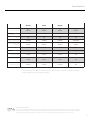 3
3
-
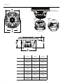 4
4
-
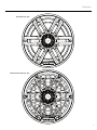 5
5
-
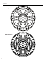 6
6
-
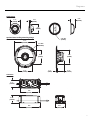 7
7
-
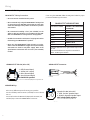 8
8
-
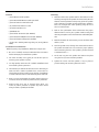 9
9
-
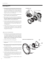 10
10
-
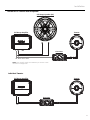 11
11
-
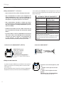 12
12
-
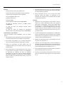 13
13
-
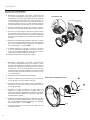 14
14
-
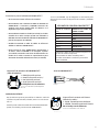 15
15
-
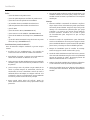 16
16
-
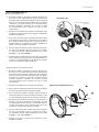 17
17
-
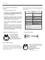 18
18
-
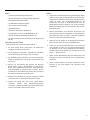 19
19
-
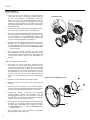 20
20
-
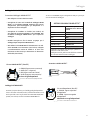 21
21
-
 22
22
-
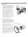 23
23
-
 24
24


Rockford Fosgate ELEMENT READY M2-65 Installation & Operation Manual
- Categoría
- Altavoces de la barra de sonido
- Tipo
- Installation & Operation Manual
En otros idiomas
- français: Rockford Fosgate ELEMENT READY M2-65
- italiano: Rockford Fosgate ELEMENT READY M2-65
- English: Rockford Fosgate ELEMENT READY M2-65
- Deutsch: Rockford Fosgate ELEMENT READY M2-65
Documentos relacionados
-
 Rockford Fosgate ELEMENT READY M0-65 Manual de usuario
-
 Rockford Fosgate M2 ELEMENT READY M2D2-10SB Manual de usuario
-
 Rockford Fosgate M1D4-10 Manual de usuario
-
 Rockford Fosgate M2WL-8 Manual de usuario
-
Rockford Fosgate M2WL-10H El manual del propietario
-
Rockford Fosgate PunchPM282HW-B Installation & Operation
-
Rockford Fosgate M1WL-65MB Instrucciones de operación
-
 Rockford Fosgate PUNCH PM2T-S Installation & Operation Manual
-
 Rockford Fosgate Element Ready M2D2-10I Installation & Operation Manual
-
Rockford Fosgate Punch PM2652W-MB Manual de usuario


