
GUÍA RÁPIDA
EP-42SIP Versión 2.0 1/1
EP-42SIP
ATENCI
Ó
N:
Antes de conectar el equipo asegúrese que la tensión
de suministro sea la adecuada.
No exponga el equipo a fuentes de calor.
La instalación debe ser realizada por personal técnico
cualificado.
INTERCOMUNICADOR AUDIO SIP
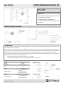
ESPECIFICACIONES Y CONEXIÓN
Alimentación POE / 5 Vcc
Consumo 10 W Máx.
Dimensiones 186 x 123 x 40 mm
Peso 1,1 kg
Acabado Acero Inoxidable
Contactos de salida
CT1 Max 24 V, 2 A
CT1 +5o 5 V 200 mA
CT2 NO-C Max 24 V, 1 A
Protección Equivalente IP-65 (con caja opcional)
Accesorios opcionales
Caja de superficie CS-EP
Caja de empotrar CE-EP
CONFIGURACIÓN
Los parámetros del equipo: IP, extensión, volumen... se configuran desde su servidor web. Se recomiendan los navegadores Firefox y Chrome. Para más detalle consulte el
manual “Optimus SIP web server configuration”.
La IP del equipo puede verse en la etiqueta ubicada en su parte posterior. En Windows 7 o superior, puede encontrarse el equipo automáticamente desde el explorador de
archivos seleccionando el icono RED. Es necesario tener la IPv6 y la detección de redes habilitada. También puede encontrarse escribiendo su dirección IPv6 directamente en el
navegador de internet. Sigue la tipología “[fe80::1a39:19ff:fexx:xxxx]” siendo las “x” los seis últimos caracteres de la dirección MAC. (Login: admin, Password: admin)
El equipo dispone de dos contactos. CT1 es un contacto abre puertas, puede activarse durante la llamada marcando un tono DTMF configurable. CT2 es un contacto de estado,
para su activación debe configurarse el sistema de la siguiente manera:
- CT2 cerrado durante la llamada. Configurar “Status Light LED2: Lit” Call successful.
- CT2 cerrado durante el establecimiento de llamada. Configurar “Status Light LED2: Lit” Call in progress.
1. Altavoz
2. Pulsador de llamada
con indicador LED
3. Micrófono

QUICK GUIDE
EP-42SIP Version 2.0 1/1
EP-42SIP
WARNING:
Make sure the power outlet conforms to the power
requirements before connecting the equipment.
Do not install the unit near heat sources.
Only qualified service personnel should be allowed to
install and operate the unit.
SIP AUDIO STATION
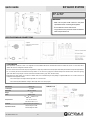
SPECIFICATIONS AND CONNECTIONS
Power Source POE / 5 Vdc
Consumption 10 W Max
Dimensions 186 x 123 x 40 mm
Weight 1,1 kg
Finish Stainless Steel
Output Contact
CT1 Max 24 V, 2 A
CT1 +5o 5 V 200 mA
CT2 NO-C Max 24 V, 1 A
Protection IP-65 Equivalent (with optional box)
Optional Accessories
Wall mounting box CS-EP
Flush mounting box CE-EP
CONFIGURATION
Device parameters: IP, extension, volume... are configured from unit’s embedded Web Server. Recommended browsers are Firefox and Chrome. For more detail, refer to
"Optimus SIP web server configuration” instruction manual.
Device’s IP can be found in a label in the rear panel. Using Windows7 or higher it is possible to discover the equipment automatically from the file browser by selecting the Network
icon. Is it necessary the have IPV6 and Network discovery enabled. You can also find it by typing its IPv6 address directly into the internet browser. It follows the typology
"[fe80::1a39:19ff:fexx:xxxx]" being the "x" the last six characters of the MAC address. (Login: admin, Password: admin)
Equipment has two output contacts. CT1 is used as door release contact, and it is activated during the call by dialling a configurable DTMF tone. CT2 is a status contact, for its
configuration set the equipment as follow:
- CT2 closed during the call. Configure “Status Light LED2: Lit” Call successful.
- CT2 closed during call establishment. Configure “Status Light LED2: Lit” Call in progress.
1. Speaker
2. Call button with LED indicator
3. Microphone
-
 1
1
-
 2
2

