Samsung DW80R9950US Guía de instalación
- Categoría
- Lavaplatos
- Tipo
- Guía de instalación
Este manual también es adecuado para

Dishwasher
Installation manual
DW80R9950* Series
DW9900R_DD68-00208A-00_EN.indd 1 12/29/2018 1:57:08 PM

Contents
English2
Contents
Safety instructions 3
Important safety instructions 3
Before using your dishwasher 5
Installation 6
Product dimensions 11
Cabinet dimensions 12
Specications 34
Scan the QR code* to view our
helpful installation videos.
* Requires reader to be installed on your
smartphone.
DW9900R_DD68-00208A-00_EN.indd 2 12/29/2018 1:57:08 PM

Safety instructions
English 3
SAVE THESE INSTRUCTIONS
Safety instructions
Throughout this manual, you will see Warning and Caution notes. The warnings, cautions,
and the important safety instructions that follow do not cover all possible conditions and
situations that may occur. It is your responsibility to use common sense, caution, and care
when installing, maintaining, and operating the dishwasher. Samsung is not liable for
damages resulting from improper use.
Important safety instructions
What the icons and signs in this installation guide mean:
WARNING
Hazards or unsafe practices that may result in severe personal injury or death.
CAUTION
Hazards or unsafe practices that may result in personal injury or property damage.
CAUTION
To reduce the risk of re, explosion, electric shock, or personal injury when using the
dishwasher, follow these basic safety precautions:
NOTE
Indicates that a risk of personal injury or material damage exists.
These warning signs are here to prevent injury to you and others.
Please follow them explicitly.
After reading this section, keep it in a safe place for future reference.
STOP
These installation instructions are intended for use by qualied installers.
If you are having problems installing this dishwasher
U.S.A
Please call: 1-800-SAMSUNG (726-7864)
1-844-SAM-PAYS (726-7297)
for assistance: www.samsung.com/us/support
CANADA
Please call: 1-800-SAMSUNG (726-7864)
for assistance: www.samsung.com/ca/support (English)
www.samsung.com/ca_fr/support (French)
DW9900R_DD68-00208A-00_EN.indd 3 12/29/2018 1:57:09 PM

Safety instructions
Safety instructions
English4
SAVE THESE INSTRUCTIONS
California Proposition 65 Warning
WARNING: Cancer and Reproductive Harm - www.P65Warnings.ca.gov
Read all instructions before using the appliance.
Install and store the dishwasher inside, away from exposure to weather.
CAUTION
• Do not install the dishwasher near electrical components. Keep the dishwasher away
from open ames.
• Do not install the dishwasher on a carpet as this is a re hazard.
• Do not install the dishwasher in a location where the water may freeze (where the
temperature falls below 32 °F (0 °C)). Frozen water in the hoses or pipes may damage
the dishwasher.
• As with all equipment using electricity, water, and moving parts, potential hazards
exist. To safely operate this appliance, become familiar with its operation and exercise
care when using it.
The dishwasher must be properly grounded. Never connect it to an ungrounded outlet.
Prior to removal of original dishwasher and the installation of your new unit, make
sure to switch off your circuit breaker. Do not connect the dishwasher until you have
completed the installation. Connecting the power cable is the last step when installing the
dishwasher.
All wiring and grounding must be done in accordance with the electrical code applicable
to the region.
GROUNDING INSTRUCTIONS
For a permanently connected appliance:
This appliance must be connected to grounded metal, a permanent wiring system, or an
equipment-grounding conductor must be run with the circuit conductors and connected to
the equipment-grounding terminal or lead on the appliance.
The dishwasher is very heavy. Do not attempt to move or carry a dishwasher alone. Two
or more people are needed to move a dishwasher and avoid potential injuries.
CAUTION
• If the power cable is damaged, it must be replaced by the manufacturer, a service
agent or similarly qualied person in order to avoid a hazard.
• Do not touch the power cable with wet hands.
• Do not connect another appliance to the same power outlet as the dishwasher.
DW9900R_DD68-00208A-00_EN.indd 4 12/29/2018 1:57:09 PM

Safety instructions
English 5
SAVE THESE INSTRUCTIONS
Make sure to use a new water supply line. Old lines are susceptible to breakage because
they become hardened and may cause property damage due to a water leakage.
The dishwasher must be connected to a hot water supply with a temperature between
120 °F (49 °C)
~
149 °F (65 °C). This temperature range provides the best washing result
and shortest cycle time. Temperature should not exceed 149 °F (65 °C) to prevent damage
to dishes.
Ensure that the water supplied to the dishwasher does not freeze. Frozen water can
damage the hoses, valves, pump, or other components.
Certied residential dishwashers are not intended for licensed food establishments.
(NSF/ANSI Standard 184 for Residential Dishwashers)
For a full list of safety information, please refer to the User Manual.
Before using your dishwasher
WARNING
Tip-Over Hazard
• Do not use the dishwasher until it is correctly installed.
• Do not push down on the dishwasher door when it is open.
• Do not place excessive weight on the dishwasher door when it is open.
Electric Shock Hazard
Failure to follow these instructions can result in death, re, or electric
shock:
• Electrically ground the dishwasher
• Connect the ground wire to the green ground connector in the junction
box.
• Do not use an extension cord.
To reduce the risk of electric shock, re, or injury to persons, the installer
must ensure that the dishwasher is completely enclosed at the time of
installation.
DW9900R_DD68-00208A-00_EN.indd 5 12/29/2018 1:57:10 PM

Installation
English6
Installation
Be sure that you or your installer follow these instructions closely so that the new
dishwasher works properly and that you are not at risk of injury when washing dishes.
STEP 1 Check the parts and tools
Before starting on the installation, prepare all the necessary tools and parts required to
install the dishwasher. This will save installation time and simplify the installation process.
Parts required
Provided with the dishwasher. Check when you unbox the dishwasher in STEP 5.
2 Installation
brackets
Kick Plate 6 screws
(for the Kick plate &
Bracket Installation)
Protective sticker
Paper ruler Nut connector &
seal (for
3
/4" 90°
tting)
6 Plastic caps
DW9900R_DD68-00208A-00_EN.indd 6 12/29/2018 1:57:12 PM

English 7
Installation
Not provided
Power cable Twist on wire
connector
Strain relief Electrical tape &
Standard duct tape
Hot water supply
line
90° Fitting (
3
/4") Tube ttings Hose clamp
Air gap Rubber connector
NOTE
For the hot water supply line – We strongly recommend using
3
/8" minimum O.D. copper
tubing with a compression tting or a exible stainless steel braided hot water supply
line.
[Warning: Do not use plastic tubing. Plastic tubing can deteriorate over time and cause a
leak inside the tube tting.]
You also need a 90° Fitting with
3
/4" N.P.T. external pipe threads on one end and a tting
sized to t your hot water supply line (copper tubing/compression tting or braided hose)
on the other.
For the power cable, we recommend a jacketed 12-2 cable with ground. Note that some
local codes may require the cable to have a BX style metal jacket.
DW9900R_DD68-00208A-00_EN.indd 7 12/29/2018 1:57:14 PM

Installation
Installation
English8
Tools required
Electric drill Safety glasses Gloves Flashlight
Adjustable wrench Wire stripper Pliers Nipper
Tape measure Pencil Phillips screwdriver Flat screwdriver
Tubing cutter Cutting knife Hole saw Level
Torx t20 Hex L-wrench
DW9900R_DD68-00208A-00_EN.indd 8 12/29/2018 1:57:15 PM

English 9
Installation
NOTE
New installation
If the dishwasher is a new installation, most of the installation work must be done before
the dishwasher is moved into place.
Replacement
If the dishwasher is replacing an old dishwasher, you must check the exising dishwasher
connections for compatibility with the new dishwasher. Repace the existing connections
as necessary.
STEP 2 Select the best location for the dishwasher
The following criteria are important to ensure the best location for the dishwasher:
• The location must have a solid oor that is able to support the weight of the
dishwasher.
• The location must be near a sink with easy access to the water supply, drain, and
electrical outlet.
NOTE
For the drain to operate properly, the dishwasher should be installed within 9.8 ft (3 m)
of the sink.
• The location must let you load your dishes into the dishwasher easily.
• The location must have sufcient space for the dishwasher door to open easily and
provide enough space between the dishwasher and the cabinet sides (at least 0.1 in
(2 mm)).
NOTE
If the dishwasher is installed in a corner, ensure that the side of the dishwasher is more
than 2 in. (50 mm) from the wall or cabinet to its right or left.
• The wall at the back must be free of obstructions.
• Make sure the cabinet for the dishwasher is secured to the oor. If the cabinet is not
secured, it may increase noise when the dishwasher is operating.
DW9900R_DD68-00208A-00_EN.indd 9 12/29/2018 1:57:15 PM

Installation
Installation
English10
If this is a new installation, follow these steps:
1. Using a 2
1
/2 inch hole saw, cut a hole into the side of the cabinet that holds the sink as
shown in Figure 1-1 below.
2. If the base inside the sink cabinet is raised above the kitchen oor and is higher than the
connections on the dishwasher, make a hole in the base inside the cabinet and in the cabinet
side as shown in Figure 1-2.
NOTE
Depending on where your electrical outlet is, you may need to cut a hole in the opposite
cabinet side.
Figure 1-1
The hole for the water supply line, drain
hose and power cables.
Figure 1-2
CAUTION
Make sure the cabinet hole is smoothened before you insert the drain hose through the
hole. A sharp edge of the cabinet hole may cause damage to the drain hose, resulting in a
leak of the hose.
DW9900R_DD68-00208A-00_EN.indd 10 12/29/2018 1:57:15 PM

English 11
Installation
Product dimensions
Front view
Side view
Rear view
Junction box
23
7
/8" (605 mm)
20
1
/2" (520 mm)
2
1
/2" (60 mm)
2
1
/2" (60 mm)
5
3
/4" (140 mm)
25" (636 mm)
You must arrange the water supply line,
power cable and drain hose in the space
behind the dishwasher.
33⅞-35" (860-890 mm)
DW9900R_DD68-00208A-00_EN.indd 11 12/29/2018 1:57:16 PM

Installation
Installation
English12
Cabinet dimensions
24" (610 mm) minimum
34⅛-35⅓" (867-897 mm)
24" (610 mm)
minimum
NOTE
This dishwasher is designed to be enclosed
on the top and on both sides by a standard
residential kitchen cabinet unit.
The installation cabinet must be clean and
free of any obstructions.
The cabinet must be at least 24 inches wide,
24 inches deep, and 34
1
/8 inches high.
For the front door of the dishwasher to be
ush with the leading edge of the counter
top, the counter top must be at least
25 inches deep.
DW9900R_DD68-00208A-00_EN.indd 12 12/29/2018 1:57:16 PM

English 13
Installation
STEP 3 Check water supply requirements and cautions
• The hot water supply line pressure must be between 20
~
120 psi (140
~
830 kPa).
• Adjust the water heater to deliver water between 120 °F (49 °C)
~
149 °F (65 °C).
- The dishwasher must be connected to a hot water supply between 120 °F
(49 °C)
~
149 °F (65 °C). This temperature range provides the best washing result
and shortest cycle time. Temperature should not exceed 149 °F (65 °C) to prevent
damage to dishes.
- Ensure that the water supply valve is turned off before connecting the hot water
supply line to the dishwasher.
- Seal the hot water supply line connections using teon tape or sealing compound to
stop any water leakage.
- The drain hose connected to the dishwasher must be run through the hole in the
side wall so it can be connected to the drain outlet of the sink. When you install the
dishwasher, ensure there is nothing on the drain hose and be careful not to damage
it during the installation process.
Figure 2
Dishwasher bottom
Hot Water
Supply Line
4¼-6¼ in.
(110-160 mm)
Power cable
Inlet valve
DW9900R_DD68-00208A-00_EN.indd 13 12/29/2018 1:57:16 PM

Installation
Installation
English14
STEP 4 Check the electrical requirements and cautions
The electrical requirements for the dishwasher are as follows:
• In the United States, install in accordance with the National Electric Code/State and
Municipal codes and/or local codes.
• In Canada, install in accordance with the Canadian Electric Code C22.1-latest edition/
Provincial and Municipal codes and/or local codes.
• For cable direct connections.
- Use exible, armored or non-metallic sheathed, copper wire with a grounding wire
that meets the wiring requirements for your local codes and ordinances.
- Use the strain relief method provided with the wiring junction box or install a U.L.-
listed/CSA-certied clamp connector to the wiring junction box. If using conduit, use
a U.L.-listed/CSA-certied conduit connector.
Figure 3
Dishwasher bottom
Hot Water
Supply Line
Power cable
2
1
/2-3
1
/2 in.
(64-89 mm)
Power cable channel
DW9900R_DD68-00208A-00_EN.indd 14 12/29/2018 1:57:16 PM

English 15
Installation
STEP 5 Unpacking and inspecting the dishwasher
Unpack the dishwasher in an open area free of obstruction both around the packaging
and overhead. We recommend that you retain all of the packing materials until the
dishwasher is fully installed and operational to ensure you have removed all the product’s
components from the packing materials prior to disposal.
Unpacking
1. Position the carton right-side-up with
top arrows pointing upwards.
2. Unbuckle or cut the straps securing the
packaging.
3. Unpack the product packaging with
care.
4. Put the straps and all of the packing
materials from around the dishwasher
inspecting them for any signs of
damage.
5. Locate and set aside the dishwasher's
kick plate. The Kick plate is attached to
packing material of the dishwasher.
Kick plate
6. Lift the dishwasher from the packing
tray, and then place it on the oor.
CAUTION
• ALWAYS LIFT THE DISHWASHER TO
MOVE IT. Sliding it over rough surfaces
can damage the dishwasher’s feet and
sliding the feet over nished surfaces
can, in some cases, damage that nish
or the underlying surface.
• Use caution, and do not grab the upper
air duct when moving the dishwasher.
7. There is also packing inside the dishwasher that you may want to leave in place until
the dishwasher is installed.
8. DO NOT, under any circumstances, remove the sound-absorbent padding that
surrounds the exterior of the tub of the dishwasher.
DW9900R_DD68-00208A-00_EN.indd 15 12/29/2018 1:57:16 PM

Installation
Installation
English16
Inspecting
Mechanical
1. Check the plastic base assembly to ensure that it is intact
2. Check the dishwasher’s feet to ensure they are in place and can be adjusted so you can
level and secure the dishwasher.
3. Check all the visible components on the bottom of the dishwasher to ensure they are
intact and secure.
4. Check the door latch, the operation of the hinges, and conrm the door is properly
secured to the dishwasher.
Plumbing
1. Check the hot water connection on the back left-side of the base of the dishwasher.
The mounting plate should be secured to the back of the base, the threads inside the
connection should be smooth and shiny, and the area should be clean and free of any
debris.
2. Make sure the dishwasher and the accessories are all included in the package to ensure
these assemblies are not cracked and that all connections are secure.
3. Check the drain hose for any holes or deformities that could allow a water leak during
draining.
Electrical
1. Conrm the junction box cover is secured to the junction box on the front right-side of
the base of the dishwasher.
2. Conrm the electrical box was not damaged during shipping and that it is secured to
the base of the dishwasher.
Appearance
1. Conrm there are no dents or scratches on the front of the dishwasher.
2. Check the edges of the doors for any roughness or cracking.
3. Check the control panel to ensure it is clear and unscratched, and that all the control
markers are in their proper places.
Parts
Conrm you have all the parts listed in STEP 1 on page 6.
DW9900R_DD68-00208A-00_EN.indd 16 12/29/2018 1:57:16 PM

English 17
Installation
STEP 6 Preparing the dishwasher
1. Attach the protective sticker (A).
- To prevent damage, put the protective sticker on the bottom of the counter top as
shown in the picture.
NOTE
• Before putting the protective sticker, clean the counter top as shown in the picture.
• For information, the length of the protective sticker is 26 inches (660 mm).
A
2. Ensure that the circuit breaker and water supply valve are turned off before
proceeding with the following steps.
CAUTION
Before you move or lay down the dishwasher for installation, make sure to adjust
the height of the legs so the legs are as short as possible. This prevents the legs from
breaking. Level the dishwasher by adjusting the height of the legs after you have the
dishwasher in place.
DW9900R_DD68-00208A-00_EN.indd 17 12/29/2018 1:57:17 PM

Installation
Installation
English18
3. Use the provided nut connector to connect the water hose to the dishwasher.
Follow these steps:
01 02 03
A
B
C
E
D F
01 Disconnect the 90° tting (A) from the hose (B).
02 Remove the seal (C) and the nut (D) from the 90° tting.
03 From the provided nut connector, separate the seal (E) and the nut (F), and then
assemble them to the 90° tting as shown in the gure. You must insert the smaller
side of the seal.
4. Then, insert the
3
/4" 90 degree tting into the inlet valve (See Figure 4-B). Tighten until
the
3
/4" tting is tight. Do not over tighten.
5. Detach the Velcro strips that secure the drain hose to the back of the dishwasher. Roll-
out the hose. Make sure there are no kinks and that the hose is not bent at any extreme
angles that could constrict the ow of water.
6. Remove the junction box cover located at the bottom front right of the dishwasher
using a screwdriver, and then Install the strain relief (Figure 4-C). Make sure to keep
the junction box cover you removed. It is used in STEP 11, Wiring Connections.
7. If the countertop is made of wood or a material that is not damaged by drilling, attach
the two (2) Installation brackets that were supplied with the dishwasher using the
supplied screws (Figure 4-A). They will be used in STEP 9, Securing the Dishwasher.
If the drain hose needs to go to the
right of the dishwasher, secure the hose
in the hose xer mounted on the base.
There are three positions the hose xer
can be installed at. To move the hose
xer, gently squeeze the xer, then
turn to the left.
Make sure to secure on the arrow-
marked area.
DW9900R_DD68-00208A-00_EN.indd 18 12/29/2018 1:57:17 PM

English 19
Installation
Figure 4
A
B
C
90° tting
Junction box
Strain relief
CAUTION
Do not overtighten the 90° Fitting. (Below 280 lb·in (31.6 N·m))
Doing so may damage the water inlet valve and cause a water leak.
DW9900R_DD68-00208A-00_EN.indd 19 12/29/2018 1:57:17 PM

Installation
Installation
English20
STEP 7 Placing the dishwasher and connecting the hot water supply line
1. Adjust the three leveling legs at the bottom of the dishwasher after measuring the
height of the cabinet opening from under the countertop to the oor. (See STEP 8,
Leveling the Dishwasher.)
2. Locate the hot water supply line and the power cable.
3. Place the dishwasher so that the hot water supply line is in the left side and the power
cable is in the right channel of the base of the dishwasher. The right-side channel for
the power cable has a built-in hook on the base so that you secure the power cable.
4. Pull the drain hose through the hole in the sink cabinet side wall. Keep it free of kinks.
5. Make sure the hot water supply line is not twisted, and then connect the hot water
supply line to the tting joint.
6. Slide the dishwasher carefully into the installation space. If possible, gently pull any
excess lengths of water supply line, drain hose, or power cable back as you move the
dishwasher. Get a second or third person to help you do this if necessary.
CAUTION
Do not place the dishwasher on the water supply line, drain hose, or power cable. Also,
make sure they are not folded or twisted.
• Make sure the supply line is properly connected.
Wrap Teon tape around every connection to prevent water leaks.
Make sure the side gaskets are inserted seamlessly. Otherwise, it may increase noise
when the dishwasher is operating.
• Make sure both side gaskets are
13
/16" to 1" (20-25 mm) backward from the front
end of the kitchen cabinet. Less distance may increase noise when the dishwasher is
operating.
DW9900R_DD68-00208A-00_EN.indd 20 12/29/2018 1:57:17 PM

English 21
Installation
Figure 5
Elbow (
3
/4" (9.5 mm))
Power cable
Side gasket
1 inch
Side gasket
Drain hose
Hot Water Supply Line
Junction box
built-in hook
Hot Water Supply Line
Inlet valve
CAUTION
Do not overtighten the 90° Fitting. (Below 280 lb·in (31.6 N·m))
Doing so may damage the water inlet valve and cause a water leak.
Make sure the dishwasher is positioned to the center.
DW9900R_DD68-00208A-00_EN.indd 21 12/29/2018 1:57:18 PM

Installation
Installation
English22
STEP 8 Leveling the dishwasher
1. Open the door and place the level
against the top of the tub on the inside
and check if the the dishwasher is level.
If it is not level, rotate the leveling legs
at the bottom front of the dishwasher
until the dishwasher is level.
See the rst note below for instructions
on adusting the height of the front legs.
2. Use the level to check if the dishwasher
is level front to back, as shown in the
gure to the right.
If the dishwasher is not level front to
back, adjust the height of the rear leg
until the dishwasher is level.
See the second note below for
instructions on adusting the the rear
leg.
3. Open the door of the dishwasher
and check if both the tub and door
clearances are correct.
If not, rotate the leveling legs on the
bottom front of the dishwasher.
You can aslo check this by placing a
level against an inside front vertical
surface of the tub.
DW9900R_DD68-00208A-00_EN.indd 22 12/29/2018 1:57:18 PM

English 23
Installation
NOTE
• If the leveling legs are rotated to the
left (clockwise), they are loosened and
the front of the dishwasher is raised. If
they are rotated to the right (counter
clockwise), they are tightened and the
front of the dishwasher is lowered.
• You can adjust the leveling legs by a
max of
16
/32" However, leveling up to
the max height is not recommended.
NOTE
To adjust the height of a rear leg, turn the
T210 Torx (at the front of the base) to the
left to raise the back of the dishwasher
using the proper tool (T20 Torx).
CAUTION
• Before you move the dishwasher for installation, make sure to adjust the height of the
legs so the legs are as short as possible. This prevents the legs from breaking. Level the
dishwasher by adjusting the height of the legs after you have the dishwasher in place.
• If the product is installed unleveled or with the leg missing, the door may not close
completely, causing a leak of steam or water.
• When adjusting the height of the dishwasher, make sure the top gasket is inserted
seamlessly underneath the top of the kitchen cabinet. Otherwise, it may increase noise
when the dishwasher is operating.
DW9900R_DD68-00208A-00_EN.indd 23 12/29/2018 1:57:18 PM

Installation
Installation
English24
STEP 9 Securing the dishwasher
You must x the dishwasher to the countertop or cabinet side walls for additional stability
and safety.
To the countertop
If the countertop is made of wood or the material will not be damaged by drilling, follow
this.
1. Put a large towel into the bottom of
the dishwasher(covering the lter) to
prevent wood shavings or a dropped
screw from falling into the sump.
2. Insert the provided brackets into the
top front holes of the dishwasher as
shown.
If the brackets are too long, cut them
down using pliers.
3. Pre-drill the overlapping holes of the
brackets.
Make sure the hole is smaller than the
diameter of the screw.
4. Tighten the provided screws.
5. Assemble the provided plastic caps as
shown.
CAUTION
• After installing the dishwasher inside
the cabinet, check if the door opens and
closes freely with no interruption with
the cabinet.
• If the plastic caps are not assembled,
water may leak and cause a re or
electric shock.
DW9900R_DD68-00208A-00_EN.indd 24 12/29/2018 1:57:19 PM

English 25
Installation
To the sides
If the countertop is made of granite, marble, or any other material that can be damaged
by drilling, follow this.
1. Put a large towel into the bottom of the
dishwasher(covering the lter) to prevent
wood shavings or a dropped screw from
falling into the sump.
2. Insert the provided brackets into the
side front holes of the dishwasher as
shown.
If the brackets are too long, cut them
down using pliers.
3. Pre-drill one hole into both sides of the
kitchen cabinet.
Make sure the hole is smaller than the
diameter of the screw.
4. Tighten the provided screws.
5. Assemble the provided plastic caps as
shown.
CAUTION
• After installing the dishwasher inside
the cabinet, check if the door opens and
closes freely with no interruption with
the cabinet.
• If the plastic caps are not assembled,
water may leak and cause a re or
electric shock.
DW9900R_DD68-00208A-00_EN.indd 25 12/29/2018 1:57:19 PM

Installation
Installation
English26
A B A B
Good
22" (560 mm)
Bad
Do not to exceed 22" (560 mm) distance
between the Caps
22" (560 mm)
CAUTION
Make sure the tub is not distorted by pressure from the screws. If the tub is distorted,
loosen the screws a little. Replace the plastic caps.
Use the paper ruler to measure the specied distance on A and B.
DW9900R_DD68-00208A-00_EN.indd 26 12/29/2018 1:57:19 PM

English 27
Installation
STEP 10 Securing
1. Check the parts on the sink to which the drain hose will be connected.
2. There are several ways to insert the drain hose into the drain hose connector of the
sink, as shown in the following gures. You must connect the drain hose in accordance
with the water pipe installation regulations in your region.
Figure 8
Case 1. Without disposal
Air gap
Hose clamp
Drain
hose
Hose clamp
Without disposal With an air gap/without disposal Without an air gap
Case 2. With disposal
Air gap
Hose clamp
Drain
hose
Hose clamp
With disposal Disposal with an air gap Without an air gap
3. Check the size of the sink’s drain hose connector. If needed, cut the drain hose so its
end ts onto the sink connector (⅝ in. or 1 in. - as shown in Figure 9 below). If the end
of the drain hose does not t onto the drain hose connector of the sink, use an adaptor
purchasable at a plumbing/hardware supply store.
DW9900R_DD68-00208A-00_EN.indd 27 12/29/2018 1:57:20 PM

Installation
Installation
English28
4. Slide a hose clamp over the end of the drain hose. Attach the drain hose to the sink
connector, slide the hose clamp to the end of the hose, and then tighten the hose
clamp.
NOTE
You must use a hose clamp. Failure to do so may cause water leakage.
5. To prevent backow, secure the drain hose to the side or back wall of the kitchen
cabinet using cable ties or other xtures. Make sure the drain hose height is at least
20 inches from the oor. (See Figure 10.)
6. When drilling a hole for the drain hose on the cabinet wall, take caution not to damage
the drain hose by sharp edges of the hole. On wooden walls, use sand paper to soften
the edges.
On metal walls, use insulation tape or duct tape to cover the sharp edges around the
hole.
7. Take caution not the damage the drain hose when installing the dishwasher on the
oor, wall, or cabinet.
NOTE
To prevent leaks or drainage problems, make sure the drain hose is not damaged, kinked, or
twisted.
8. Do not cut the wrinkled area of the drain hose to t the size. When arranging the drain
hose, take caution not to contact on sharp edges of the cabinet or under-sink.
CAUTION
• Be careful when cutting off the end of the drain hose as there is a risk of injury. Clean
around the sink’s drain connection so that it does not damage the hose. Check for any
foreign items in the drain hose and remove them.
• When arranging the drain hose, make sure the drain hose is not cut, torn, or broken by
any sharp edges of the oor, the product itself, or the cabinet. A damaged drain hose
causes a leak.
• Make sure to unplug the food disposal.
DW9900R_DD68-00208A-00_EN.indd 28 12/29/2018 1:57:20 PM

English 29
Installation
Figure 9
If necessary, cut off the dotted line of the
drain hose to t the size.
1 in.
(25 mm)
7
/8 in.
(22 mm)
5
/8 in.
(16 mm)
Figure 10
Min. 20 in.
(508 mm)
Drain hose
Dishwasher
Sink
To prevent backow for models without
the air gap, secure the drain hose to the
side wall of the kitchen cabinet using cable
ties or other xtures. Make sure the drain
hose is high at least 20 inches from the
bottom.
DW9900R_DD68-00208A-00_EN.indd 29 12/29/2018 1:57:20 PM

Installation
Installation
English30
STEP 11 Wiring connections
1. Before connecting the power cable to the dishwasher, make sure the circuit breaker is off.
2. In the junction box located at the front bottom right of the dishwasher, nd the three
power wires from the dishwasher including the grounding line.
3. Pass the power cable through the strain relief, and then into the junction box
(Figure 11).
4. Connect the black wire of the dishwasher to the black wire of the power cable by
insertng both into a wire nut. and then rotating the wire connector as shown in
Figure 12.
Connect the white wire to the white wire and the green to the green in the same
manner.
5. Recheck each wire to ensure it is connected correctly and securely.
Each colored wire should be connected to the corresponding wire of the same color.
White should be connected to white, black to black, and green to green.
6. Reconnect the junction box cover on the dishwasher.
Figure 11
Black to black
Power cable
Junction box
Strain relief
White to white
Green to green
(Ground to ground)
DW9900R_DD68-00208A-00_EN.indd 30 12/29/2018 1:57:21 PM

English 31
Installation
Figure 12
WARNING
• Electrical Shock Hazard
To avoid electrical shock, do not work
on an energized circuit. Doing so could
result in serious injury or death. Only
qualied electricians should perform
electrical work. Do not attempt any
work on the dishwasher electric supply
circuit until you are certain the circuit is
de-energized.
• Fire Hazard
To avoid a re hazard, make sure
electrical work is properly installed.
Only qualied electricians should
perform electrical work.
NOTE
Recheck each wire to ensure it is connected correctly and securely.
Each colored wire should be connected to the corresponding wire of the same color.
DW9900R_DD68-00208A-00_EN.indd 31 12/29/2018 1:57:21 PM

Installation
Installation
English32
STEP 12 Completing the installation
1. Open the door and remove all foam, paper packaging, and unnecessary parts.
2. Turn on the circuit breaker you turned off before you began the installation.
3. Open the water supply valve to supply water to the dishwasher.
4. Turn on the dishwasher, and then select and run a cycle.
CAUTION
Make sure to check for water leakage on both ends of the water supply line and drain
hose connector.
5. Check if the dishwasher turns on properly and check also if there is any leak. If there is
no problem, turn the dishwasher off. Skip Steps 6 through 10 and go to Step 11.
6. If the leakage check code of “LC” appears on the window panel, press and hold the
Start button for more than 3 seconds to start draining. When the draining is complete,
unplug the dishwasher and close the water supply valve.
7. Check if the inlet valve leaks. If so, reconnect the 90º tting with the hot water supply
line because they are not properly connected.
8. Once the leak is stopped, lay down the dishwasher as shown, and wipe out moisture
from the water leakage sensor.
Water leakage sensor
9. Plug the dishwasher. Then, open the water supply valve and try a cycle.
10. If the “LC” information code continues to appear on the window panel, contact a local
service center.
11. Finally, attach the kick plate to the bottom of the dishwasher. While keeping the rubber
skirt of the door taut, push the kick plate from the front of the rubber skirt inward
underneath the door of the dishwasher. Make sure the gaskets of the kick plate are
ush with the oor and side walls. Then, tighten the screws to x the plate.
DW9900R_DD68-00208A-00_EN.indd 32 12/29/2018 1:57:21 PM

English 33
Installation
Kick plate
Gasket
CAUTION
Make sure the kick plate does not interfere with the dishwasher's door opening and
closing.
DW9900R_DD68-00208A-00_EN.indd 33 12/29/2018 1:57:21 PM

Specications
English34
Specications
Power supply 120 V, 15 A, 60 Hz AC
Water pressure 20
~
120 psi (140
~
830 kPa)
Dimensions
(Width×Depth×Height)
23
7
/8 x 25 x 33
7
/8 in.
(605 x 636 x 860 mm)
Minimum inlet water temperature 120 °F (49 °C)
NOTE
Specications are subject to change without notice for quality improvement purposes.
The actual appearance of the dishwasher may differ from the illustrations in this manual.
DW9900R_DD68-00208A-00_EN.indd 34 12/29/2018 1:57:21 PM

Memo
English 35
DW9900R_DD68-00208A-00_EN.indd 35 12/29/2018 1:57:21 PM

DD68-00208A-00
DW9900R_DD68-00208A-00_EN.indd 36 12/29/2018 1:57:21 PM

Lavavajillas
Manual de instalación
Serie DW80R9950*
DW9900R_DD68-00208A-00_MES.indd 1 1/3/2019 1:01:41 PM

Contenidos
Español2
Contenidos
Instrucciones de seguridad 3
Instrucciones de seguridad importantes 3
Antes de usar la lavavajillas 5
Instalación 6
Dimensiones del producto 11
Dimensiones del gabinete 12
Especicaciones 34
Escanee el código QR* para ver
videos útiles de instalación.
* Debe tener un lector instalado en su teléfono
inteligente.
DW9900R_DD68-00208A-00_MES.indd 2 1/3/2019 1:01:41 PM

Instrucciones de seguridad
Español 3
CONSERVE ESTAS INSTRUCCIONES
Instrucciones de seguridad
A lo largo de este manual, encontrará notas de Advertencia y Precaución. Las siguientes
advertencias, precauciones e instrucciones de seguridad importantes no cubren todas las posibles
condiciones y situaciones que pueden ocurrir. Es su responsabilidad actuar con sentido común,
precaución y cuidado cuando instale, realice el mantenimiento y ponga en funcionamiento la
lavavajillas. Samsung no se responsabiliza por los daños ocasionados por un uso inadecuado.
Instrucciones de seguridad importantes
Signicado de los íconos y señales de esta guía de instalación:
ADVERTENCIA
Peligros o prácticas inseguras que pueden causar lesiones físicas graves o la muerte.
PRECAUCIÓN
Peligros o prácticas inseguras que pueden causar lesiones físicas o daños materiales.
PRECAUCIÓN
Para reducir el riesgo de incendio, explosión, descargas eléctricas o lesiones físicas cuando usa
esta lavavajillas, siga estas instrucciones de seguridad básicas:
NOTA
Indica un riesgo de lesión o daño material.
Estas señales de advertencia sirven para evitar que usted y otras personas sufran daños.
Sígalas explícitamente.
Después de leer esta sección, guárdela en un lugar seguro para consultas futuras.
ATENCIÓN
Estas instrucciones de instalación están dirigidas a instaladores calicados.
Si tiene problemas al instalar esta lavavajillas
ESTADOS UNIDOS
Llame al: 1-800-SAMSUNG (726-7864)
1-844-SAM-PAYS (726-7297)
para recibir asistencia: www.samsung.com/us/support
CANADÁ
Llame al: 1-800-SAMSUNG (726-7864)
para recibir asistencia: www.samsung.com/ca/support (English)
www.samsung.com/ca_fr/support (French)
DW9900R_DD68-00208A-00_MES.indd 3 1/3/2019 1:01:41 PM

Instrucciones de seguridad
Instrucciones de seguridad
Español4
CONSERVE ESTAS INSTRUCCIONES
Advertencia de la Propuesta 65 de California
ADVERTENCIA: Cáncer y daño reproductivo - www.P65Warnings.ca.gov
Lea todas las instrucciones antes de usar el electrodoméstico.
Instale y guarde la lavavajillas en un lugar interior, no expuesto a los factores climáticos.
PRECAUCIÓN
• No instale la lavavajillas cerca de componentes eléctricos. Mantenga la lavavajillas alejada de
llamas abiertas.
• No instale la lavavajillas sobre una alfombra ya que existe peligro de incendio.
• No instale la lavavajillas en áreas donde el agua se congele (donde la temperatura descienda
por debajo de 32 ˚F (0 ˚C)). El agua congelada en las mangueras o en las cañerías puede dañar
la lavavajillas.
• Al igual que con cualquier equipo que requiere electricidad, agua y piezas movibles, existen
riesgos potenciales. Para usar este electrodoméstico en forma segura, familiarícese con su
funcionamiento y manéjelo con cuidado cuando lo use.
Esta lavavajillas debe conectarse a tierra correctamente. Nunca la conecte a un tomacorriente sin
conexión a tierra.
Antes de quitar la lavavajillas original e instalar la nueva unidad, asegúrese de desactivar su
disyuntor. No conecte la lavavajillas hasta haber completado la instalación. El último paso de la
instalación de la lavavajillas es la conexión del cable de alimentación.
Todo el cableado y la conexión a tierra deben realizarse en conformidad con el código eléctrico
vigente en la región.
INSTRUCCIONES DE CONEXIÓN A TIERRA
Para un electrodoméstico con conexión permanente:
Este electrodoméstico debe estar conectado a un metal con conexión a tierra, un sistema de
cableado permanente o a un conductor con conexión a tierra del equipo a los conductores del
circuito y a la terminal con conexión a tierra del equipo.
La lavavajillas es muy pesada. No intente mover o trasladar una lavavajillas usted solo. Se
necesitan dos o más personas para mover una lavavajillas y evitar lesiones potenciales.
PRECAUCIÓN
• Si se daña el cable de alimentación, este deberá ser reemplazado por el fabricante, su agente
de reparaciones o una persona igualmente calicada a n de evitar accidentes.
• No toque el cable de alimentación con las manos mojadas.
• No conecte otro electrodoméstico en el mismo tomacorriente donde está enchufada la
lavavajillas.
DW9900R_DD68-00208A-00_MES.indd 4 1/3/2019 1:01:42 PM

Instrucciones de seguridad
Español 5
CONSERVE ESTAS INSTRUCCIONES
Asegúrese de utilizar un conducto nuevo. Los conductos viejos pueden romperse debido a que se
endurecen y pueden ocasionar daños materiales por pérdidas de agua.
La lavavajillas debe estar conectada al suministro de agua caliente con una temperatura entre
120 ˚F (49 ˚C) y 149 °F (65 ˚C). Este rango de temperatura ofrece un mejor resultado en el lavado
y un ciclo más corto. La temperatura no deberá exceder los 149 ˚F (65 ˚C) para no dañar la vajilla.
Asegúrese de que el agua provista a la lavavajillas no se congele. El agua congelada puede dañar
las mangueras, válvulas, bombas u otros componentes.
Las lavavajillas residenciales certicadas no han sido diseñadas para los establecimientos
alimentarios autorizados.
(Estándar NSF/ANSI 184 para Lavavajillas de Uso Residencial )
Para obtener una lista completa de información sobre seguridad, remítase al Manual del usuario.
Antes de usar la lavavajillas
ADVERTENCIA
Riesgo de vuelco
• No utilice la lavavajillas hasta que no esté correctamente instalada.
• No ejerza presión sobre la puerta de la lavavajillas cuando está abierta.
• No coloque excesivo peso sobre la puerta de la lavavajillas cuando está
abierta.
Riesgo de descarga eléctrica
El incumplimiento de estas instrucciones puede tener como resultado la muerte,
incendios o descargas eléctricas:
• Conecte a tierra la lavavajillas.
• Conecte el cable a tierra a la conexión a tierra de color verde de la caja de
conexiones.
• No utilice un cable prolongador.
Para reducir el riesgo de descarga eléctrica, incendio o lesiones físicas,
el instalador debe asegurarse de que la lavavajillas esté completamente
ensamblada en el momento de la instalación.
DW9900R_DD68-00208A-00_MES.indd 5 1/3/2019 1:01:42 PM

Instalación
Español6
Instalación
Asegúrese de que usted o su instalador siga estas instrucciones minuciosamente para que su
nueva lavavajillas funcione adecuadamente y no existan riesgos de sufrir lesiones al lavar la
vajilla.
PASO 1 Verique las piezas y las herramientas
Antes de comenzar la instalación, prepare todas las herramientas y piezas necesarias requeridas
para instalar la lavavajillas. Esto ahorrará tiempo y simplicará el proceso de instalación.
Piezas necesarias
Provistas con la lavavajillas. Verique al desempacar la lavavajillas en el PASO 5.
2 ménsulas de
instalación
Placa de protección 6 tornillos
(para la instalación de
la placa de protección
y la ménsula)
Autoadhesivo
protector
Regla de papel Conector de tuerca y
sello (para adaptador
de
3
/4" de 90°)
6 tapas plásticas
DW9900R_DD68-00208A-00_MES.indd 6 1/3/2019 1:01:44 PM

Español 7
Instalación
No provisto
Cable de alimentación Conector de resorte Alivio de tensión Cinta aislante y cinta
americana estándar
Conducto de
suministro de agua
caliente
Adaptador de 90°
(de
3
/4")
Adaptador del tubo Abrazadera de
manguera
Espacio de aire Conector de goma
NOTA
Para el conducto de suministro de agua caliente – Recomendamos especialmente usar un tubo
de cobre de diámetro exterior de un mínimo de
3
/8" con adaptador de compresión o un conector
exible de acero inoxidable para el suministro de agua caliente.
[Advertencia: No utilice tubos de plástico. Los tubos de plástico se pueden deteriorar con el
tiempo y causar ltraciones en el adaptador del tubo.]
Se necesitan roscas para el tubo externo con un adaptador de 90° para tubo cónico de
3
/4" en un
extremo, y en el otro, roscas que se adapten al conducto de suministro de agua caliente (tubo de
cobre/adaptador de compresión, manguera trenzada).
Para el cable de alimentación, recomendamos utilizar un cable recubierto de 12-2 con conexión
a tierra. Tenga en cuenta que algunos códigos locales pueden requerir que el cable tenga un
recubrimiento de metal del tipo BX.
DW9900R_DD68-00208A-00_MES.indd 7 1/3/2019 1:01:46 PM

Instalación
Instalación
Español8
Herramientas requeridas
Taladro eléctrico Lentes de seguridad Guantes Linterna
Llave ajustable Alicate pelacable Pinza Alicate de corte
Cinta métrica Lápiz Destornillador
Phillips
Destornillador plano
Cortatubos Cúter Fresa para escariar Nivel
Torx t20 Llave en forma
de L para cabezas
hexagonales
DW9900R_DD68-00208A-00_MES.indd 8 1/3/2019 1:01:47 PM

Español 9
Instalación
NOTA
Instalación nueva
Si la instalación del lavavajillas es nueva, la mayor parte del trabajo debe realizarse antes de
colocar el lavavajillas en su lugar.
Reemplazo
Si el lavavajillas reemplazara a un lavavajillas anterior, debe vericar que las conexiones
existentes sean compatibles con el nuevo lavavajillas. Reemplace las conexiones existentes si
fuera necesario.
PASO 2 Elección de la mejor ubicación para la lavavajillas
Los siguientes criterios son importantes para garantizar la mejor ubicación de la lavavajillas:
• La ubicación debe tener un piso macizo que pueda soportar el peso del lavavajillas.
• La ubicación deberá ser cercana al fregadero con un acceso fácil al suministro de agua,
desagüe y tomacorriente.
NOTA
Para que el desagüe funcione correctamente, la lavavajillas debe estar instalada a 9.8 pies
(3 m) del fregadero.
• La ubicación debe permitirle colocar la vajilla dentro del lavavajillas con facilidad.
• La ubicación debe contar con espacio suciente para que la puerta de la lavavajillas pueda
abrirse fácilmente y que quede espacio suciente entre la lavavajillas y los laterales del
gabinete (por lo menos 0.1 pulgadas (2 mm)).
NOTA
Si la lavavajillas se instalara en un rincón, asegúrese de que el lateral de la lavavajillas esté a
más de 2 pulgadas (50 mm) de la pared o del gabinete hacia su derecha o izquierda.
• La pared trasera no debe presentar obstrucciones.
• Asegúrese de que el gabinete de la lavavajillas esté asegurado al piso. Si el gabinete no está
asegurado, puede aumentar el ruido durante el funcionamiento de la lavavajillas.
DW9900R_DD68-00208A-00_MES.indd 9 1/3/2019 1:01:47 PM

Instalación
Instalación
Español10
Si se trata de una instalación nueva, siga estos pasos:
1. Utilizando una fresa para escariar de 2
1
/2 pulgadas, realice una perforación en la pared del
gabinete que soporta el fregadero como se detalla en la Figura 1-1 a continuación.
2. Si la base dentro del gabinete del fregadero se eleva sobre el piso de la cocina y es más
alta que las conexiones en la lavavajillas, debe hacerse un agujero en la base dentro del
gabinete y en el lateral del gabinete como se detalla en la Figura 1-2
.
NOTA
Dependiendo del lugar donde se encuentre el tomacorriente, puede ser necesario realizar un
agujero en el lado opuesto al gabinete.
Figura 1-1
El agujero para el conducto, la manguera de
desagüe y los cables de alimentación.
Figura 1-2
PRECAUCIÓN
Asegúrese de que los bordes del oricio del gabinete estén lisos antes de insertar la manguera de
drenaje. Un borde alado del oricio del gabinete puede causar daños a la manguera de drenaje y
provocar pérdidas.
DW9900R_DD68-00208A-00_MES.indd 10 1/3/2019 1:01:47 PM

Español 11
Instalación
Dimensiones del producto
Vista frontal
Vista lateral
Vista posterior
Caja de
conexiones
23
7
/8" (605 mm)
20
1
/2" (520 mm)
2
1
/2" (60 mm)
2
1
/2" (60 mm)
5
3
/4" (140 mm)
25" (636 mm)
Acomode el conducto, el cable de alimentación y
la manguera de desagüe en el espacio detrás de la
lavavajillas.
33⅞-35" (860-890 mm)
DW9900R_DD68-00208A-00_MES.indd 11 1/3/2019 1:01:47 PM

Instalación
Instalación
Español12
Dimensiones del gabinete
24" (610 mm) mínimo
34⅛-35⅓" (867-897 mm)
24" (610 mm)
mínimo
NOTA
Esta lavavajillas está diseñada para
colocarse entre los lados y encima de un
gabinete en una cocina residencial estándar.
El gabinete para la instalación debe estar
limpio y libre de obstrucciones.
El gabinete debe tener por lo menos
24 pulgadas de ancho, 24 pulgadas de
profundidad y 34
1
/8 pulgadas de altura.
Para que la puerta delantera de la
lavavajillas esté nivelada con el borde
delantero de la encimera, la encimera
debe estar por lo menos a 25 pulgadas de
profundidad.
DW9900R_DD68-00208A-00_MES.indd 12 1/3/2019 1:01:48 PM

Español 13
Instalación
PASO 3 Verique los requisitos para el suministro de agua y precauciones
• La presión del conducto de agua caliente debe estar entre 20 y 120 psi (140 y 830 kPa).
• Ajuste el calentador de agua para obtener una temperatura de agua entre 120 ˚F (49 ˚C) y
149 ˚F (65 ˚C).
- La lavavajillas debe estar conectada al suministro de agua caliente entre 120 ˚F (49 ˚C) y
149 °F (65 ˚C). Este rango de temperatura ofrece un mejor resultado en el lavado y un ciclo
más corto. La temperatura no deberá exceder los 149 ˚F (65 ˚C) para no dañar la vajilla.
- Asegúrese de que la válvula del suministro de agua esté cerrada antes de conectar el
conducto de agua caliente al lavavajillas.
- Selle las conexiones del conducto de agua caliente con cinta teón o pasta de sellado para
detener cualquier pérdida de agua.
- La manguera de desagüe conectada al lavavajillas debe pasar por el oricio de la
pared lateral a n de conectarla a la salida del desagüe del fregadero. Cuando instale la
lavavajillas, asegúrese de que no haya nada en la manguera de desagüe y tenga cuidado de
no dañarla durante el proceso de instalación.
Figura 2
Parte inferior de la lavavajillas
Conducto de
suministro de
agua caliente
4¼-6¼ in
(110-160 mm)
Cable de alimentación
Válvula de entrada
DW9900R_DD68-00208A-00_MES.indd 13 1/3/2019 1:01:48 PM

Instalación
Instalación
Español14
PASO 4 Verique los requisitos eléctricos y advertencias
Los requisitos eléctricos para la lavavajillas son los siguientes:
• En los Estados Unidos, instalar de conformidad con el Código Eléctrico Nacional/códigos
estatales y municipales y/o códigos locales.
• En Canadá, instalar de conformidad con el Código Eléctrico Canadiense C22.1-última edición/
códigos provinciales y municipales y/o códigos locales.
• Para conexiones directas de cable.
- Utilice un cable de cobre recubierto enfundado no metálico con una conexión a tierra que
cumpla con los requisitos de cableado de los códigos y ordenanzas locales.
- Utilice el método del aliviador de tensión provisto con la caja de conexiones de cableado
o instale una abrazadera de conector incluida en U.L./certicada por CSA- en la caja de
conexión de cableado. Si utilizara un conducto, utilice un conector de conducto incluido en
U.L./con certicación CSA.
Figura 3
Parte inferior de la lavavajillas
Conducto de
suministro de
agua caliente
Cable de
alimentación
2
1
/2-3
1
/2 pulgadas
(64-89 mm)
Canal del cable de
alimentación
DW9900R_DD68-00208A-00_MES.indd 14 1/3/2019 1:01:48 PM

Español 15
Instalación
PASO 5 Desempacar e inspeccionar el lavavajillas
Desempaque la lavavajillas en una zona libre de obstrucciones ya sea alrededor de la caja como
en la parte superior. Recomendamos que conserve todos los materiales del empaque hasta que
la lavavajillas esté completamente instalada y en funcionamiento para asegurarse de que haya
retirado todas las piezas del producto de la caja antes de desecharla.
Desempaque
1. Ubique el lado derecho de la caja con las
echas superiores señalando hacia arriba.
2. Desate o corte las correas que aseguran la
caja.
3. Desempaque el producto con cuidado.
4. Coloque las correas y todos los materiales
de empaque que se encuentren alrededor
de la lavavajillas y verique que no tengan
daño alguno.
5. Localice y separe la placa de protección
de la lavavajillas. La placa de protección
está sujeta al material de empaque de la
lavavajillas.
Placa de protección
6. Levante la lavavajillas de la bandeja de la
caja, y luego colóquela sobre el piso.
PRECAUCIÓN
• SIEMPRE LEVANTE LA LAVAVAJILLAS PARA
MOVERLA. Arrastrar la lavavajillas sobre
supercies irregulares puede dañar los
soportes, y arrastrar los soportes sobre
supercies lisas puede, en algunos casos,
dañar la capa superior o la capa inferior de
dicha supercie.
• Cuando mueva la lavavajillas, tenga
cuidado de no sujetarla por al conducto de
aire superior.
7. También se encuentra material de empaque dentro de la lavavajillas, que tal vez quiera
conservar hasta que haya instalado la máquina.
8. NO retire, bajo ninguna circunstancia, el aislante de protección que rodea el exterior de la
cuba de la lavavajillas.
DW9900R_DD68-00208A-00_MES.indd 15 1/3/2019 1:01:48 PM

Instalación
Instalación
Español16
Inspección
Mecánica
1. Verique el montaje de la base de plástico para asegurarse que esté intacto.
2. Verique los soportes de la lavavajillas para asegurarse de que estén en su lugar y que
puedan ajustarse con el n de nivelar y asegurar la lavavajillas.
3. Verique todas las piezas visibles en la parte inferior de la lavavajillas para asegurar que
estén intactas y seguras.
4. Verique la traba de la puerta, el funcionamiento de las bisagras, y conrme que la puerta
esté correctamente asegurada a la lavavajillas.
Cañerías
1. Verique la conexión de agua caliente en el lado izquierdo trasero de la base de la lavavajillas.
La placa de montaje debe estar asegurada a la parte trasera de la base, las roscas de la
conexión deben ser lisas y brillosas y la zona debe estar limpia y libre de fragmentos.
2. Revise que la lavavajillas y todos los accesorios estén incluidos en la caja para asegurarse de
que estos montajes no estén dañados y que todas las conexiones estén aseguradas.
3. Verique que la manguera de desagüe no tenga perforaciones o deformidades que ocasionen
la ltración de agua durante el desagüe.
Eléctrica
1. Conrme que la tapa de la caja de conexiones esté asegurada a la caja de conexiones en el
lado derecho delantero de la base de la lavavajillas.
2. Conrme que la caja eléctrica no se haya dañado durante el transporte y que esté asegurada a
la base de la lavavajillas.
Apariencia
1. Conrme que no haya abolladuras o raspones en la parte del frente de la lavavajillas.
2. Verique que los bordes de la puerta no tengan ninguna imperfección o daño.
3. Verique el panel de control para asegurarse de que esté limpio y sin daño, y que todos los
vericadores de control estén en su lugar.
Piezas
Verique que tenga todas las piezas enumeradas en el PASO 1 en la página 6.
DW9900R_DD68-00208A-00_MES.indd 16 1/3/2019 1:01:48 PM

Español 17
Instalación
PASO 6 Preparación del lavavajillas
1. Una el autoadhesivo protector (A).
- Para evitar daños, coloque el autoadhesivo protector en la parte inferior de la encimera
como se muestra en la imagen.
NOTA
• Antes de aplicar el autoadhesivo protector, limpie la encimera como se muestra en la imagen.
• Tenga en cuenta que el autoadhesivo protector mide 26 pulgadas (660 mm) de largo.
A
2. Asegúrese que el disyuntor y la válvula del suministro de agua estén desactivados antes de
continuar con los siguientes pasos.
PRECAUCIÓN
Antes de mover o apoyar la lavavajillas para su instalación, debe asegurarse de ajustar la altura
de las patas de modo que estas sean lo más cortas posible. Esto evita que las patas se rompan.
Nivele la lavavajillas ajustando la altura de las patas luego de colocar la máquina en su lugar.
DW9900R_DD68-00208A-00_MES.indd 17 1/3/2019 1:01:49 PM

Instalación
Instalación
Español18
3. Use el conector de tuerca provisto para conectar la manguera de agua al lavavajillas.
Siga estos pasos:
01 02 03
A
B
C
E
D F
01 Desconecte el adaptador de 90° (A) de la manguera (B).
02 Retire el sello (C) y la tuerca (D) del adaptador de 90°.
03 En el conector de tuerca provisto, separe el sello (E) y la tuerca (F) y luego ensámblelos en el
adaptador de 90° como se ilustra en la gura. Debe insertar el lado más pequeño del sello.
4. Luego, inserte el adaptador de
3
/4" 90 grados en la válvula de entrada (ver la Figura 4-B).
Ajuste hasta que el adaptador de
3
/4" quede ajustado. No lo ajuste demasiado.
5. Separe las tiras que velcro que jan la manguera de desagüe a la parte trasera de la
lavavajillas. Desenrolle la manguera. Asegúrese de que no haya dobleces y que la manguera
no está inclinada en ninguno de los ángulos extremos que podrían obstruir el ujo del agua.
6. Con un destornillador quite la tapa de la caja de las conexiones ubicada en la parte inferior
derecha del frente de la lavavajillas y luego instale el alivio de tensión (Figura 4 - C).
Asegúrese de conservar la tapa de la caja de conexiones que quitó. Se utiliza en el PASO 11,
Conexiones del cableado.
7. Si la encimera es de madera o si se trata de un material que no se daña al perforarlo, coloque
las dos (2) ménsulas de instalación que fueron provistas con la lavavajillas utilizando los
tornillos provistos (Figura 4 - A). Se utilizarán en el PASO 9, Fijación de la lavavajillas.
Si la manguera de desagüe debe ir a la
derecha de la lavavajillas, asegúrela en el
jador de la manguera montado en la base.
El jador de la manguera puede instalarse
en tres posiciones. Para mover el jador de
la manguera, presiónelo suavemente para
que gire hacia la izquierda.
Asegúrelo en la zona marcada con la echa.
DW9900R_DD68-00208A-00_MES.indd 18 1/3/2019 1:01:49 PM

Español 19
Instalación
Figura 4
A
B
C
Adaptador de 90°
Caja de conexiones
Alivio de tensión
PRECAUCIÓN
No ajuste demasiado el adaptador de 90°. (Menos de 280 lb·en (31.6 N·m))
Si lo hiciera, podría dañar la válvula de entrada de agua y ocasionar una pérdida de agua.
DW9900R_DD68-00208A-00_MES.indd 19 1/3/2019 1:01:50 PM

Instalación
Instalación
Español20
PASO 7 Colocación del lavavajillas y conexión del conducto del suministro de agua caliente
1. Regule las tres patas niveladoras en la parte inferior de la lavavajillas después de medir la
altura de la abertura del gabinete desde abajo de la encimera hasta el piso. (Ver el PASO 8,
Nivelación de la lavavajillas.)
2. Ubique el conducto del agua caliente y el cable de alimentación.
3. Coloque la lavavajillas de manera tal que el conducto del agua caliente esté en el lado
izquierdo y el cable de alimentación quede ubicado en el canal derecho de la base de la
lavavajillas. El canal del lado derecho para el cable de alimentación cuenta con un gancho
incorporado que permite asegurar el cable.
4. Saque la manguera de desagüe por el oricio en la pared lateral del gabinete del fregadero.
Asegúrese de que no haya dobleces.
5. Asegúrese de que el conducto del agua caliente no esté torcido y luego conecte el conducto de
agua caliente a la junta del adaptador.
6. Deslice la lavavajillas con cuidado hacia su espacio de instalación. De ser posible, retire
suavemente todo tramo en exceso del conducto de agua, manguera de desagüe o cable de
alimentación mientras mueve la lavavajillas. Si fuera necesario, acuda a otras personas que lo
ayuden a realizar esta tarea.
PRECAUCIÓN
No coloque el lavavajillas sobre el conducto, la manguera de desagüe o el cable de alimentación.
También asegúrese de que no estén enroscados o doblados.
• Asegúrese de que el conducto de agua caliente esté bien conectado.
Envuelva con cinta Teón todas las conexiones para evitar pérdidas.
Asegúrese de que los burletes laterales estén perfectamente insertados. De lo contrario, puede
aumentar el ruido durante el funcionamiento de la lavavajillas.
• Asegúrese de que los dos burletes laterales estén entre
13
/16" y 1" (20-25 mm) del extremo
frontal del gabinete de la cocina. Si la distancia es inferior puede aumentar el ruido durante el
funcionamiento de la lavavajillas.
DW9900R_DD68-00208A-00_MES.indd 20 1/3/2019 1:01:50 PM

Español 21
Instalación
Figura 5
Codo de (
3
/4" (9.5 mm))
Cable de alimentación
Burlete lateral
1 in
Burlete lateral
Manguera de desagüe
Conducto de suministro
de agua caliente
Caja de conexiones
gancho incorporado
Conducto de suministro de agua caliente
Válvula de entrada
PRECAUCIÓN
No ajuste demasiado el adaptador de 90°. (Menos de 280 lb·en (31.6 N·m))
Si lo hiciera, podría dañar la válvula de entrada de agua y ocasionar una pérdida de agua.
Asegúrese de que la lavavajillas esté ubicada en el centro.
DW9900R_DD68-00208A-00_MES.indd 21 1/3/2019 1:01:50 PM

Instalación
Instalación
Español22
PASO 8 Nivelación del lavavajillas
1. Abra la puerta y coloque el nivel contra la
parte superior de la cuba desde adentro y
verique si la lavavajillas está nivelada.
Si no lo está, gire las patas niveladoras en
la parte inferior delantera de la lavavajillas
hasta que quede nivelada.
Vea la primera nota debajo de las
instrucciones sobre el ajuste de la altura de
las patas delanteras.
2. Utilice el nivel para vericar si la
lavavajillas está nivelada de adelante hacia
atrás, como se muestra en la gura de la
derecha.
Si la lavavajillas no está nivelada de
adelante hacia atrás, ajuste la altura de la
pata trasera hasta que la lavavajillas esté
nivelada.
Vea la segunda nota debajo de las
instrucciones sobre el ajuste de la pata
trasera.
3. Abra la puerta de la lavavajillas y verique
que tanto la separación de la cuba como la
de la puerta sean correctas.
Si no es así, gire las patas niveladoras en la
parte inferior delantera de la lavavajillas.
También puede vericar esto ubicando un
nivel contra una supercie interior vertical
delantera de la cuba.
DW9900R_DD68-00208A-00_MES.indd 22 1/3/2019 1:01:50 PM

Español 23
Instalación
NOTA
• Si gira las patas niveladoras hacia la
izquierda (en el sentido de las agujas
del reloj), estas se aojan y la parte
delantera del lavavajillas se levanta. Si
las gira hacia la derecha (en el sentido
contrario al de las agujas del reloj),
se ajustan y la parte delantera del
lavavajillas baja.
• Puede regular las patas niveladoras
un máximo de
16
/32" No obstante, no es
recomendable ajustarlas a esta altura
máxima.
NOTA
Para ajustar la altura de una pata trasera,
gire el Torx 210 (en el lado delantero de
la base) hacia la izquierda para levantar la
parte posterior de la lavavajillas utilizando la
herramienta apropiada (Torx T20).
PRECAUCIÓN
• Antes de mover la lavavajillas para su instalación, debe asegurarse de ajustar la altura de
las patas de modo que estas sean lo más cortas posible. Esto evita que las patas se rompan.
Nivele la lavavajillas ajustando la altura de las patas luego de colocar la máquina en su lugar.
• Si instala el producto desnivelado o sin una pata, la puerta puede que no cierre
completamente, lo que daría lugar a fugas de vapor o de agua.
• Cuando ajuste la altura de la lavavajillas, asegúrese de que el burlete superior esté
perfectamente insertado debajo de la parte superior del gabinete de la cocina. De lo contrario,
puede aumentar el ruido durante el funcionamiento de la lavavajillas.
DW9900R_DD68-00208A-00_MES.indd 23 1/3/2019 1:01:51 PM

Instalación
Instalación
Español24
PASO 9 Asegurar la lavavajillas
La lavavajillas debe jarse a la encimera o a las paredes laterales para mayor estabilidad y
seguridad.
A la encimera
Si la encimera está hecha de madera de un material que no se daña por la perforación, siga las
siguientes instrucciones.
1. Coloque una toalla grande en la parte
inferior de la lavavajillas (que cubra el
ltro) para evitar que caigan restos de
madera o un tornillo dentro del sumidero
del sumidero.
2. Inserte las ménsulas que se proveen en los
oricios de la parte superior delantera de
la lavavajillas.
Si las ménsulas son demasiado largas,
córtelas utilizando un alicate de corte.
3. Perfore los oricios superpuestos de los
soportes.
Asegúrese de que el oricio sea más
pequeño que el diámetro del tornillo.
4. Ajuste los tornillos provistos.
5. Ensamble las tapas plásticas provistas
como se ilustra.
PRECAUCIÓN
• Luego de instalar la lavavajillas en el
gabinete, asegúrese de que la puerta
se abra y se cierre libremente sin que
interera el gabinete.
• Si no se ensamblan las tapas plásticas,
puede haber una pérdida de agua que
cause un incendio o descarga eléctrica.
DW9900R_DD68-00208A-00_MES.indd 24 1/3/2019 1:01:51 PM

Español 25
Instalación
Hacia los laterales
Si la encimera está hecha de granito, mármol o cualquier otro material que no se daña por la
perforación, siga las siguientes instrucciones.
1. Coloque una toalla grande en la parte
inferior de la lavavajillas (que cubra el
ltro) para evitar que caigan restos de
madera o un tornillo dentro del sumidero
del sumidero.
2. Inserte las ménsulas que se proveen en los
oricios de la parte lateral delantera de la
lavavajillas.
Si las ménsulas son demasiado largas,
córtelas utilizando un alicate de corte.
3. Perfore un oricio en ambos lados del
gabinete de la cocina.
Asegúrese de que el oricio sea más
pequeño que el diámetro del tornillo.
4. Ajuste los tornillos provistos.
5. Ensamble las tapas plásticas provistas
como se ilustra.
PRECAUCIÓN
• Luego de instalar la lavavajillas en el
gabinete, asegúrese de que la puerta
se abra y se cierre libremente sin que
interera el gabinete.
• Si no se ensamblan las tapas plásticas,
puede haber una pérdida de agua que
cause un incendio o descarga eléctrica.
DW9900R_DD68-00208A-00_MES.indd 25 1/3/2019 1:01:51 PM

Instalación
Instalación
Español26
A B A B
Correcto
22" (560 mm)
Incorrecto
La distancia entre las tapas no debe
superar las 22" (560 mm)
22" (560 mm)
PRECAUCIÓN
Asegúrese de que la cuba no se deforme a causa de la presión de los tornillos. Si la cuba se
deforma, desajuste los tornillos levemente. Reemplace las tapas plásticas.
Use la regla de papel para medir la distancia especicada en A y B.
DW9900R_DD68-00208A-00_MES.indd 26 1/3/2019 1:01:52 PM

Español 27
Instalación
PASO 10 Ajuste
1. Verique las piezas del fregadero a las cuales se conectará la manguera de desagüe.
2. Hay muchas maneras de insertar la manguera de desagüe en el conector de la manguera de
desagüe del fregadero, como se muestra en las siguientes guras. Debe conectar la salida del
desagüe conforme a las reglamentaciones de instalación de tuberías de agua de su región.
Figura 8
Caso 1. Sin triturador
Espacio de aire
Abrazadera de
manguera
Manguera
de desagüe
Abrazadera de manguera
Sin triturador Con un espacio de aire/ sin triturador Sin un espacio de aire
Caso 2. Con triturador
Espacio de aire
Abrazadera de
manguera
Manguera
de desagüe
Abrazadera de manguera
Con triturador Triturador con un espacio de aire Sin un espacio de aire
3. Verique el tamaño del conector de la manguera de desagüe del fregadero. Si fuera necesario,
corte la manguera de desagüe para que encaje en el conector del fregadero (⅝ pulgada
o 1 pulgada, como se muestra en la Figura 9 siguiente). Si el extremo de la manguera de
desagüe no calza en el conector de la manguera de desagüe del fregadero, use un adaptador
que pueda adquirir en un negocio de suministros de plomería/ ferretería.
DW9900R_DD68-00208A-00_MES.indd 27 1/3/2019 1:01:53 PM

Instalación
Instalación
Español28
4. Deslice una abrazadera de manguera en el extremo de la manguera de desagüe. Conecte la
manguera de desagüe al conector del fregadero, deslice la abrazadera de la manguera hacia el
extremo nal de la manguera, y luego ajuste la abrazadera de la manguera.
NOTA
Debe utilizar una abrazadera de manguera. Si no lo hace, es posible que haya pérdidas de agua.
5. Para evitar el ujo de retorno, asegure la manguera de desagüe en la pared lateral o trasera
del gabinete de la cocina mediante sujetacables o con otras monturas. Asegúrese de que la
manguera de desagüe se encuentre al menos a una altura de 20 pulgadas del piso.
(Consulte la Figura 10.)
6. Cuando realice un agujero en la pared del gabinete para la manguera de desagüe, tenga
cuidado de que los bordes losos del oricio no dañen la manguera. Si las paredes son de
madera, lije los bordes para suavizarlos.
Si las paredes son de metal, use cinta aislante o cinta americana para cubrir los bordes losos
alrededor del agujero.
7. Tenga cuidado de no dañar la manguera de desagüe al instalar la lavavajillas en el piso, la
pared o el gabinete.
NOTA
Para evitar pérdidas o problemas de drenaje, asegúrese de que la manguera de desagüe no esté
dañada, retorcida o enredada.
8. No corte la zona retorcida de la manguera de desagüe para que se adapte al tamaño. Cuando
acomode la manguera de desagüe, tenga cuidado de no tocar los bordes losos del gabinete o
bajo el fregadero.
PRECAUCIÓN
• Tenga cuidado al cortar el extremo de la manguera de desagüe ya que podría lastimarse.
Limpie el área de conexión del desagüe del fregadero para evitar que la manguera se dañe.
Verique que no haya objetos extraños en la manguera de desagüe y quítelos.
• Cuando acomode la manguera de desagüe, asegúrese de que no tenga cortes causados por los
bordes losos del piso, el producto o el gabinete. Una manguera dañada causa pérdidas.
• Asegúrese de desconectar el triturador de comida.
DW9900R_DD68-00208A-00_MES.indd 28 1/3/2019 1:01:53 PM

Español 29
Instalación
Figura 9
Si es necesario, corte por la línea punteada de la
manguera de desagüe para que se adapte al tamaño.
1 pulgada
(25 mm)
7
/8 pulgada
(22 mm)
5
/8 pulgada
(16 mm)
Figura 10
Mín. 20 pulgada
(508 mm)
Manguera de desagüe
Lavavajillas
Fregadero
Para evitar el ujo de retorno en los modelos
sin espacio de aire, asegure la manguera de
desagüe en la pared lateral del gabinete de
la cocina mediante sujetacables o con otras
monturas. Asegúrese de que la manguera de
desagüe se encuentre al menos a una altura de
20 pulgadas de la parte inferior.
DW9900R_DD68-00208A-00_MES.indd 29 1/3/2019 1:01:53 PM

Instalación
Instalación
Español30
PASO 11 Conexiones del cableado
1. Antes de conectar el cable de alimentación a la lavavajillas, asegúrese de desactivar el
disyuntor.
2. En la caja de conexiones que se encuentra ubicada en la parte delantera derecha inferior de
la lavavajillas, busque los tres cables de alimentación de la lavavajillas inclusive la conexión a
tierra.
3. Pase el cable de alimentación al alivio de tensión, y luego dentro de la caja de conexiones
(Figura 11).
4. Conecte el cable negro de la lavavajillas al cable negro del cable de alimentación insertando
ambos en la tuerca para cable y luego rote el conector de cables, como se muestra en la
Figura 12.
Conecte el cable blanco al cable blanco y el verde al verde del mismo modo.
5. Revise nuevamente cada uno de los cables para asegurarse de que están conectados
correctamente y en una manera segura.
Cada cable de un color debe conectarse con el cable del mismo color correspondiente.
El cable blanco debe conectarse con el blanco, el negro con el negro y el verde con el verde.
6. Reconecte la tapa de la caja de conexiones de la lavavajillas.
Figura 11
Negro con negro
Cable de alimentación
Caja de conexiones
Alivio de tensión
Blanco con blanco
Verde con verde
(Tierra a tierra)
DW9900R_DD68-00208A-00_MES.indd 30 1/3/2019 1:01:53 PM

Español 31
Instalación
Figura 12
ADVERTENCIA
• Riesgo de descarga eléctrica
Para evitar descargas eléctricas, no
manipule un circuito energizado. Si lo
hiciera, podría causar lesiones graves
o incluso la muerte. Solo los técnicos
de servicio calicados pueden realizar
conexiones eléctricas. No intente manipular
el circuito de suministro eléctrico de la
lavavajillas hasta que no esté seguro de
que está desenergizado.
• Riesgo de incendio
Para evitar el riesgo de incendio, asegúrese
de que la instalación eléctrica sea correcta.
Solo los técnicos de servicio calicados
pueden realizar conexiones eléctricas.
NOTA
Revise nuevamente cada uno de los cables para asegurarse de que están conectados
correctamente y en una manera segura.
Cada cable de un color debe conectarse con el cable del mismo color correspondiente.
DW9900R_DD68-00208A-00_MES.indd 31 1/3/2019 1:01:53 PM

Instalación
Instalación
Español32
PASO 12 Finalización de la instalación
1. Abra la puerta y quite todas las piezas innecesarias, goma espuma y empaque de papel.
2. Active el disyuntor desactivado antes de comenzar la instalación.
3. Abra la válvula del suministro de agua para suministrar agua a la lavavajillas.
4. Encienda la lavavajillas y luego seleccione y ejecute un ciclo.
PRECAUCIÓN
Verique las ltraciones de agua en ambos extremos del conducto de agua y en el conector de la
manguera de desagüe.
5. Verique si la lavavajillas se enciende correctamente o si hay alguna pérdida. Si no hay
ningún problema, apague la lavavajillas. Omita los pasos 6 a 10 y consulte el paso 11.
6. Si aparece el código de vericación de pérdidas “LC” en el panel, mantenga presionado el
botón Start (Inicio) durante más de 3 segundos para comenzar el drenaje. Al nalizar el
drenaje, desenchufe la lavavajillas y cierre la válvula del suministro de agua.
7. Revise si hay pérdida en la válvula de entrada. Si es así, vuelva a conectar el adaptador de 90°
con el conducto de agua caliente, pues la conexión no es correcta.
8. Una vez contenida la fuga, apoye la lavavajillas como se muestra y seque la humedad del
sensor de pérdidas de agua.
Sensor de pérdidas de agua
9. Enchufe la lavavajillas. Luego, abra la válvula de suministro de agua y ejecute un ciclo.
10. Si el código de información “LC” continúa apareciendo en el panel, comuníquese con un centro
de servicio técnico local.
11. Finalmente, coloque la placa de protección en la parte inferior de la lavavajillas. Mientras
mantiene tenso el faldón de caucho de la puerta, empuje la placa de protección desde la parte
delantera del faldón hacia adentro por debajo de la puerta de la lavavajillas. Asegúrese de que
los burletes de la placa de protección estén nivelados a la perfección con el piso y las paredes
laterales. Luego ajuste los tornillos para jar la placa.
DW9900R_DD68-00208A-00_MES.indd 32 1/3/2019 1:01:54 PM

Español 33
Instalación
Placa de
protección
Burlete
PRECAUCIÓN
Asegúrese de que la placa de protección no interera con la apertura y cierre de la puerta de la
lavavajillas.
DW9900R_DD68-00208A-00_MES.indd 33 1/3/2019 1:01:54 PM

Especicaciones
Español34
Especicaciones
Suministro eléctrico 120 V, 15 A, 60 Hz CA
Presión de agua 20
~
120 psi (140
~
830 kPa)
Dimensiones
(Ancho×Profundidad×Altura)
23
7
/8 x 25 x 33
7
/8 pulgadas.
(605 x 636 x 860 mm)
Temperatura mínima del agua en la entrada 120 °F (49 °C)
NOTA
Las especicaciones están sujetas a cambios sin previo aviso a los efectos de las mejoras de
calidad. La apariencia real de la lavavajillas puede diferir de las ilustraciones de este manual.
DW9900R_DD68-00208A-00_MES.indd 34 1/3/2019 1:01:54 PM

Notas
Español 35
DW9900R_DD68-00208A-00_MES.indd 35 1/3/2019 1:01:54 PM

DD68-00208A-00
DW9900R_DD68-00208A-00_MES.indd 36 1/3/2019 1:01:54 PM
-
 1
1
-
 2
2
-
 3
3
-
 4
4
-
 5
5
-
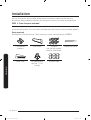 6
6
-
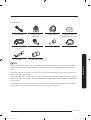 7
7
-
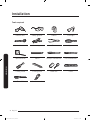 8
8
-
 9
9
-
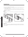 10
10
-
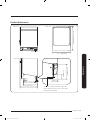 11
11
-
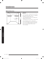 12
12
-
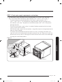 13
13
-
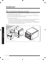 14
14
-
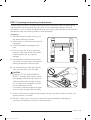 15
15
-
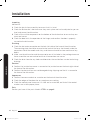 16
16
-
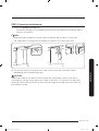 17
17
-
 18
18
-
 19
19
-
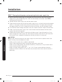 20
20
-
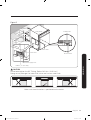 21
21
-
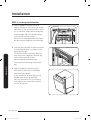 22
22
-
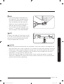 23
23
-
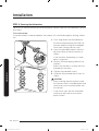 24
24
-
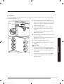 25
25
-
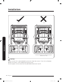 26
26
-
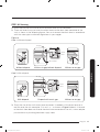 27
27
-
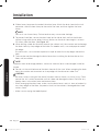 28
28
-
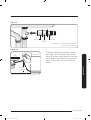 29
29
-
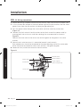 30
30
-
 31
31
-
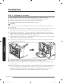 32
32
-
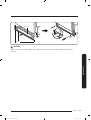 33
33
-
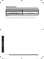 34
34
-
 35
35
-
 36
36
-
 37
37
-
 38
38
-
 39
39
-
 40
40
-
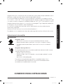 41
41
-
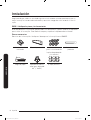 42
42
-
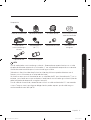 43
43
-
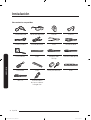 44
44
-
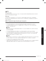 45
45
-
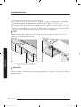 46
46
-
 47
47
-
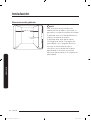 48
48
-
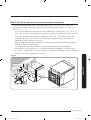 49
49
-
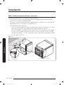 50
50
-
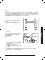 51
51
-
 52
52
-
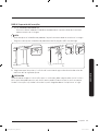 53
53
-
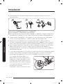 54
54
-
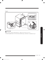 55
55
-
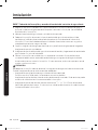 56
56
-
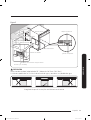 57
57
-
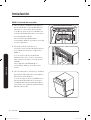 58
58
-
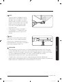 59
59
-
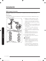 60
60
-
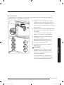 61
61
-
 62
62
-
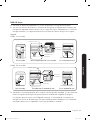 63
63
-
 64
64
-
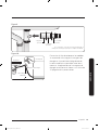 65
65
-
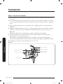 66
66
-
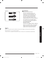 67
67
-
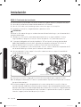 68
68
-
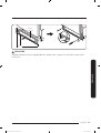 69
69
-
 70
70
-
 71
71
-
 72
72


Samsung DW80R9950US Guía de instalación
- Categoría
- Lavaplatos
- Tipo
- Guía de instalación
- Este manual también es adecuado para
en otros idiomas
Artículos relacionados
-
Samsung DW80K5050UG/AA-00 Manual de usuario
-
Samsung DW80R5061UG Guía de instalación
-
-
Samsung DW80R9950US Manual de usuario
-
Samsung DW60A6090FS Guía del usuario
-
-
Samsung DW80CB5450 Manual de usuario
-
Samsung 959316 Manual de usuario
-
-