La página se está cargando...

2
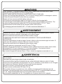
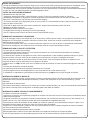
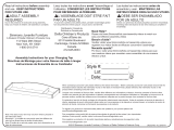
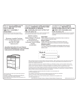
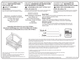
WARNING
FALL HAZARD - To prevent death or serious injury, always keep child within arm’s reach.
Read all instructions before use of the changing table.
KEEP THESE INSTRUCTIONS IN A SAFE PLACE FOR FUTURE USE.
Inspect the changing table periodically. Do not use the changing table if it is damaged or broken.
Contact Simmons Juvenile Furniture with any questions.
Tighten all loose screws and bolts before each use.
The maximum recommended weight of the child is 30lbs for the changing table.
This dressing kit must be attached to a level, stable and structurally sound peice of furniture. The
surface must have a minimum width of 45-7/8” and a minimum depth of 17-1/4”. These
measurements should include only the flat level surface of the furniture.
The changing pad used should be 34" x 16" with a maximum thickness of 1".
RISQUE DE CHUTE – Afin de prévenir tout risque de décès ou de blessure grave, toujours
demeurer à portée de bras de l’enfant placé sur la table à langer.
Bien lire toutes les instructions avant d’utiliser la table à langer
CONSERVER CES INSTRUCTIONS DANS UN ENDROIT SÛR POUR RÉFÉRENCE
ULTÉRIEURE.
Inspecter régulièrement la table à langer. Ne pas l’utiliser si elle est endommagée ou brisée. Si
vous avez des questions contactez Simmons Juvenile Furniture.
Serrer tous les boulons et vis desserrés avant chaque usage.
Le poids maximum recommandé est de 30 livres (13,6kg).
La table à langer doit être fixée à un meuble de niveau, stable et de structure solide, d’une surface
minimumde 45-7/8” po et d’au moins 17-1/4” po de profondeur. Ces mesures doivent
essentiellement correspondre à lasurface plane du meuble.
Le coussin à langer doit mesurer 34 po x 16 po et avoir une épaisseur maximale de 1 po
AVERTISSEMENT
PELIGRO DE CAIDAS - Para prevenir la muerte o lesiones graves, mantenga al niño al alcance
de sus manos.
Lea todas las instrucciones antes de usar el cambiador.
COLOQUE ESTAS INSTRUCCIONES EN UN LUGAR SEGURO PARA SU USO FUTURO.
Inspeccione este cambiador periodicamente. No use el cambiador si esta dañado o roto. Póngase
en contacto con Simmons Juvenile Furniture para formular preguntas.
Apriete los tornillos y pernos flojos antes de cada uso.
El paso maximo recomendado 30 libras (13.6 g).
Este vestidor debe ser conectado a un nivel, estable y a una pieza estrúcturalmente sano de
muebles. Lasuperficies debe tener una anchura minima de 45-7/8” y una profundidad minima de
17-1/4”. Estas medidas debenincluír solo la superficié plana de los muebles.
La almohadilla usada debe ser 34 x 16 pulgadas con un grosor máximo de 1 pulgada.
ADVERTENCIA
La página se está cargando...

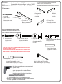
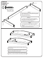
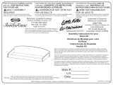
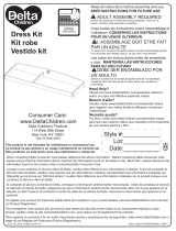
Parts:
Pièces:
Piezas:
4
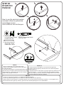
Phillips Screwdriver (Not Provided)
Tournevis’Phillips’(Non Prévu)
Destornillardor’Phillips’(No siempre)
CAUTION: DO NOT USE A POWER SCREWDRIVER THEY CAN CAUSE
SCREWS TO BREAK OR STRIP.
ATTENTION: NE PAS UTILISER UN TOURNEVIS ÉLECTRIQUE CARLE
VIS PEUVENT CASSER OU PERDRE LEURS FILETS.
PRECAUCIÓN: NO USE UN DESTORNILLADOR ELÉCTRICO PORQUE
PUEDEN HACER QUE LOS TORNILLOS SE ROMPAN O RUEDEN.
Drill: Only use to drill holes do not use to Install
screws or bolts
Perceuse : utiliser uniquement pour percer desTrous,
et non pour poser des vis ou des Boulons.
El taladro: sólo uso para taladrar hoyos.
NoUtilice instalar los tornillos ni los cerrojos
1/8” drill bit: available from your local hardware store
Mèche de 1/8 po : disponible auprès de votre quincaillerie locale.
1/8” broca: disponible de su ferretería local
The following tools and parts are required:
Outils et pièces nécessaires de:
Necesitan las siguientes herramientas y piezas:
# 24229
# 5464
# 5535
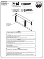
M4 Hex Wrench (Provided)
M4 Clé À Six Pans (Fournie)
M4 Llave hexagonal (Se incluye)
D. Right side x1
Côté droit
Lado derecho
# 24230
E. Center Rail x1
Centre Ferrviaire
Centro de Ferrocarril
F. 32mm Screw x3
Vis 32mm
Tornillo 32mm
G. M6 x 35mm Bolt x4
Boulons M6 x 35mm
Pernos M6 x 35mm
# 5750
J. Cam bolt x2
Goujon D’Assemblage Rapide
Perno De Leva
# 5749
H. Cam lock x2
Vis D’Assemblage Rapide
Cerradura de Leva
A. Back rail x1
Traverse Arière
Baranda de atras
# 24226
# 24228
C. Left side x1
Côté gauche
Lado izquierdo
# 24227
B. Front rail x1
Traverse avant
Baranda delantera
NOTE: FASTENERS ARE SHOWN FULL SIZE
REMARQUE: LES DISPOSITIFS DE FIXATION SONT
MONTRÉS EN TAILLE RÉELLE
NOTA: LOS PERNOS SE MUESTRAN EN TAMAÑO REAL
Hardware kit - part# 24231
L'ensemble de quincaillerie - pièce n°24231
El kit de herramientas - Pieza # 24231
M3 x32mm Dowel x2
Goujon M3 x 32mm
Pasador M3 x 32mm
#4021
K.
La página se está cargando...

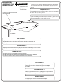
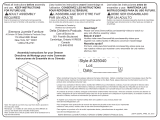
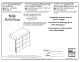
STEP #2
ÉTAPE N°2
PASO #2
6
A
ÉTAPE NO 2
PASO #2
STEP #2
H
J
K
E
1.Insert Cam Bolt (Part J) into Front Rail (Part B).
2. Insert (1) cam lock (part H) into the holes on the side of
the center rail (part E).
3. Line up the cam bolt (part J) and dowel (part K) at the back
of the front rail; from step #1 with the holes in the end of the
center rail (part E). Insert and turn the cam lock clockwise
to tighten using a phillips screwdriver.
1. Insert le boulon à came (pièce J) en Traverse avant (pièce B).
2. Insert (1) serrures (pièce H) dans les trous sur le côté de la glissière
médiane (pièce E).
3. Alignez le boulon à came (pièce J) et goujon (pièce K) à l'arrière du rail
avant; de l'étape n ° 1 avec les trous dans la fin de la glissière médiane
(pièce E). Insérer et tourner la came de verrouillage dans le sens horaire
pour serrer l'aide d'un tournevis cruciforme.
1. Inserte (1) perno de leva (Pieza J) en la Baranda delantera (Pieza B).
2. Inserte (1) cerraduras (pieza H) en los orificios en el lado del carril del centro (Pieza E).
3. Alinear el perno de leva (Pieza J) y el pasador (Prueba 4) en la parte posterior del riel frontal, el paso # 1 con los agujeros en el
extremo del carril centro (pieze E). Inserte y gire la leva de la derecha para apretar con un destornillador.
How to use the cam lock system
comment utiliser le système de
verrouillage à came
cómo utilizar la leva de bloqueo
J. Cam bolt x1
Boulon D’Assemblage Rapide
Perno de Leva
H. Cam lock x1
Vis D’Assemblage Rapide
Cerradura de Leva
M3 x32mm Dowel x1
Goujon M3 x 32mm
Pasador M3 x 32mm
K.
La página se está cargando...
La página se está cargando...
Transcripción de documentos
WARNING FALL HAZARD - To prevent death or serious injury, always keep child within arm’s reach. Read all instructions before use of the changing table. KEEP THESE INSTRUCTIONS IN A SAFE PLACE FOR FUTURE USE. Inspect the changing table periodically. Do not use the changing table if it is damaged or broken. Contact Simmons Juvenile Furniture with any questions. Tighten all loose screws and bolts before each use. The maximum recommended weight of the child is 30lbs for the changing table. This dressing kit must be attached to a level, stable and structurally sound peice of furniture. The surface must have a minimum width of 45-7/8” and a minimum depth of 17-1/4”. These measurements should include only the flat level surface of the furniture. The changing pad used should be 34" x 16" with a maximum thickness of 1". AVERTISSEMENT RISQUE DE CHUTE – Afin de prévenir tout risque de décès ou de blessure grave, toujours demeurer à portée de bras de l’enfant placé sur la table à langer. Bien lire toutes les instructions avant d’utiliser la table à langer CONSERVER CES INSTRUCTIONS DANS UN ENDROIT SÛR POUR RÉFÉRENCE ULTÉRIEURE. Inspecter régulièrement la table à langer. Ne pas l’utiliser si elle est endommagée ou brisée. Si vous avez des questions contactez Simmons Juvenile Furniture. Serrer tous les boulons et vis desserrés avant chaque usage. Le poids maximum recommandé est de 30 livres (13,6kg). La table à langer doit être fixée à un meuble de niveau, stable et de structure solide, d’une surface minimumde 45-7/8” po et d’au moins 17-1/4” po de profondeur. Ces mesures doivent essentiellement correspondre à lasurface plane du meuble. Le coussin à langer doit mesurer 34 po x 16 po et avoir une épaisseur maximale de 1 po ADVERTENCIA PELIGRO DE CAIDAS - Para prevenir la muerte o lesiones graves, mantenga al niño al alcance de sus manos. Lea todas las instrucciones antes de usar el cambiador. COLOQUE ESTAS INSTRUCCIONES EN UN LUGAR SEGURO PARA SU USO FUTURO. Inspeccione este cambiador periodicamente. No use el cambiador si esta dañado o roto. Póngase en contacto con Simmons Juvenile Furniture para formular preguntas. Apriete los tornillos y pernos flojos antes de cada uso. El paso maximo recomendado 30 libras (13.6 g). Este vestidor debe ser conectado a un nivel, estable y a una pieza estrúcturalmente sano de muebles. Lasuperficies debe tener una anchura minima de 45-7/8” y una profundidad minima de 17-1/4”. Estas medidas debenincluír solo la superficié plana de los muebles. La almohadilla usada debe ser 34 x 16 pulgadas con un grosor máximo de 1 pulgada. 2 Parts: Pièces: Piezas: Hardware kit - part# 24231 L'ensemble de quincaillerie - pièce n°24231 El kit de herramientas - Pieza # 24231 The following tools and parts are required: Outils et pièces nécessaires de: Necesitan las siguientes herramientas y piezas: C. Left side x1 Côté gauche Lado izquierdo # 24228 A. Back rail x1 Traverse Arière Baranda de atras # 24226 D. Right side x1 Côté droit Lado derecho # 24229 E. Center Rail x1 Centre Ferrviaire Centro de Ferrocarril # 24230 B. Front rail x1 Traverse avant Baranda delantera # 24227 NOTE: FASTENERS ARE SHOWN FULL SIZE REMARQUE: LES DISPOSITIFS DE FIXATION SONT MONTRÉS EN TAILLE RÉELLE NOTA: LOS PERNOS SE MUESTRAN EN TAMAÑO REAL F. 32mm Screw x3 Vis 32mm Tornillo 32mm # 5535 G. M6 x 35mm Bolt x4 Boulons M6 x 35mm Pernos M6 x 35mm # 5464 J. H. Cam lock x2 Vis D’Assemblage Rapide Cerradura de Leva # 5749 K. M3 x32mm Dowel x2 Goujon M3 x 32mm Pasador M3 x 32mm #4021 CAUTION: DO NOT USE A POWER SCREWDRIVER THEY CAN CAUSE SCREWS TO BREAK OR STRIP. ATTENTION: NE PAS UTILISER UN TOURNEVIS ÉLECTRIQUE CARLE VIS PEUVENT CASSER OU PERDRE LEURS FILETS. PRECAUCIÓN: NO USE UN DESTORNILLADOR ELÉCTRICO PORQUE PUEDEN HACER QUE LOS TORNILLOS SE ROMPAN O RUEDEN. Phillips Screwdriver (Not Provided) Tournevis’Phillips’(Non Prévu) Destornillardor’Phillips’(No siempre) Cam bolt x2 Goujon D’Assemblage Rapide Perno De Leva # 5750 M4 Hex Wrench (Provided) M4 Clé À Six Pans (Fournie) M4 Llave hexagonal (Se incluye) Drill: Only use to drill holes do not use to Install screws or bolts Perceuse : utiliser uniquement pour percer desTrous, et non pour poser des vis ou des Boulons. El taladro: sólo uso para taladrar hoyos. NoUtilice instalar los tornillos ni los cerrojos 1/8” drill bit: available from your local hardware store Mèche de 1/8 po : disponible auprès de votre quincaillerie locale. 1/8” broca: disponible de su ferretería local 4 STEP #2 ÉTAPE N°2 PASO #2 How to use the cam lock system comment utiliser le système de verrouillage à came cómo utilizar la leva de bloqueo J. Cam bolt x1 H. Cam lock x1 Vis D’Assemblage Rapide Boulon D’Assemblage Rapide Perno de Leva Cerradura de Leva E J K. M3 x32mm Dowel x1 Goujon M3 x 32mm Pasador M3 x 32mm K A H STEP #2 1.Insert Cam Bolt (Part J) into Front Rail (Part B). 2. Insert (1) cam lock (part H) into the holes on the side of the center rail (part E). 3. Line up the cam bolt (part J) and dowel (part K) at the back of the front rail; from step #1 with the holes in the end of the center rail (part E). Insert and turn the cam lock clockwise to tighten using a phillips screwdriver. ÉTAPE NO 2 1. Insert le boulon à came (pièce J) en Traverse avant (pièce B). 2. Insert (1) serrures (pièce H) dans les trous sur le côté de la glissière médiane (pièce E). 3. Alignez le boulon à came (pièce J) et goujon (pièce K) à l'arrière du rail avant; de l'étape n ° 1 avec les trous dans la fin de la glissière médiane (pièce E). Insérer et tourner la came de verrouillage dans le sens horaire pour serrer l'aide d'un tournevis cruciforme. PASO #2 1. Inserte (1) perno de leva (Pieza J) en la Baranda delantera (Pieza B). 2. Inserte (1) cerraduras (pieza H) en los orificios en el lado del carril del centro (Pieza E). 3. Alinear el perno de leva (Pieza J) y el pasador (Prueba 4) en la parte posterior del riel frontal, el paso # 1 con los agujeros en el extremo del carril centro (pieze E). Inserte y gire la leva de la derecha para apretar con un destornillador. 6-
 1
1
-
 2
2
-
 3
3
-
 4
4
-
 5
5
-
 6
6
-
 7
7
-
 8
8


Delta Children Castille Changing Top Assembly Instructions
- Tipo
- Assembly Instructions
- Este manual también es adecuado para
en otros idiomas
- français: Delta Children Castille Changing Top
- English: Delta Children Castille Changing Top
Artículos relacionados
-
 Delta Children Augusta Changing Top Assembly Instructions
-
 Delta Children Castille Changing Top Assembly Instructions
-
 Delta Children Madisson Changing Top Assembly Instructions
-
Delta Children Kingsley Changing Topper Assembly Instructions
-
Delta Children Chevron Changing Top Assembly Instructions
-
 Delta Children Belmont 4 Drawer Dresser Assembly Instructions
-
 Delta Children Emma 4 Drawer Dresser Assembly Instructions
-
 Delta Children Hanover Park Crib 'N' More Assembly Instructions
-
 Delta Children Disney Mickey Icon Changing Top Assembly Instructions
-
 Delta Children Grow Assembly Instructions


