ATEN VE200 Guía de inicio rápido
- Categoría
- Extensores de consola
- Tipo
- Guía de inicio rápido
Este manual también es adecuado para

VE200 Audio/Video Extender User Guide
VE200 Système d'extension audio/vidéo Manuel d'utilisation
VE200 Audio/Grakverlängerung Benutzerhandbuch
VE200 Sistema de extensión audio/gráca Manual del usuario
www.aten.com
www.aten.com
www.aten.com
www.aten.com
Conguration requise
Périphérique (s) source
Le composant suivant doit être installé sur le périphérique source ou sur l'ordinateur
agissant en tant que source du contenu audio/VGA :
• Connecteur HDB-15
• Prise audio
Périphérique d'afchage
• Un périphérique d'afchage VGA, SVGA, XGA, SXGA, UXGA ou multisync ou un
récepteur équipé d'un connecteur HDB-15
Câbles
• Connectez le périphérique source à l'unité locale VE200L à l'aide du câble audio/VGA
fourni avec le système d'extension vidéo VE200.
• Si vous utilisez le VE200 dans une installation d'extension vidéo (avec le VS1504/
VS1508 et VB552 d'ATEN, par exemple), utilisez un câble de catégorie 5e pour
connecter les appareils.
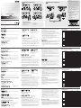
Description du matériel (A)
A. VE200L – Vue avant
1. Port série RS-232
2. Port d'entrée audio
3. Port d'entrée vidéo
4. Bouton de sélection du port RS-232 local
5. Voyant du port RS-232
6. Voyant d'alimentation
Voraussetzungen
Signalquelle (n)
Auf den Signalquellen oder Computern, die das VGA-/Audiosignal senden, muss mindestens
Folgendes installiert sein:
• HDB-15-Anschluss
• Audio-Buchse
Anzeigegerät
• Ein VGA-, SVGA-, XGA-, SXGA
, UXGA
- oder MultiSync-Anzeigegerät mit HDB-15-
Eingang
Kabel
• Verbinden Sie die Signalquelle über das mitgelieferte VGA-/Audiokabel mit dem VE200L.
• Falls Sie das Gerät in einer Reihenschaltung installieren (z.B. mit einem VS1504/VS1508
und VB552 von ATEN), verwenden Sie ein Kat. 5e-Kabel, um die Einheiten miteinander zu
verbinden.
Hardwareübersicht (A)
A Vorderseitige Ansicht des VE200L
1. Serieller RS-232-Port
2. Audio-Eingang
3. Video-Eingang
4. Lokale, RS-232 Portauswahl (Drucktaste)
5. LED-Anzeige für RS-232 Port
6. LED-Betriebsanzeige
B. VE200L rückseitige Ansicht
1. Stromeingangsbuchse
2. Buchsen für Direktverbindung Gerät auf Gerät
Requisitos
Dispositivo (s) fuente
En los dispositivos fuente de señal de audio/VGA u ordenadores que se conectan al
equipo debe estar instalado lo siguiente:
• Conector HDB de 15 patillas
• Conector de audio
Dispositivo de visualización
• Un dispositivo de visualización VGA, SVGA, XGA, SXGA, UXGA o multisync o un
receptor con un conector HDB de 15 patillas
Cables
• Conecte el dispositivo fuente a la unidad local VE200L mediante el cable de audio/
VGA incluido con el sistema de extensión gráca VE200.
• Si utiliza el VE200 en una instalación de extensión gráca (con el VS1504/VS1508 y
VB552 de ATEN, por ejemplo), use un cable de Cat. 5e para conectar los dispositivos.
Presentación del hardware (A)
A. VE200L – Vista frontal
1. Puerto serie RS-232
2. Entrada de audio
3. Entrada de vídeo
B. VE200L – Vista posterior
1. Entrada de alimentación
2. Puerto de unidad a unidad
3. Salida de vídeo
B. VE200L – Vue arrière
1. Prise d'alimentation
2. Port d'unité à unité
3. Port de sortie vidéo
4. Port de sortie audio
5. Port série RS-232
D. VE200R – Vue arrière
1. Prise d'alimentation
2. Connecteur infrarouge
3. Port d'unité à unité
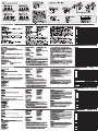
Installation du matériel (B)
• Avant de démarrer la procédure d'installation, assurez-vous que tous les
périphériques à connecter sont éteints.
• An d'éviter d'endommager votre installation, vériez que tous les périphériques sont
correctement reliés à la terre. Veuillez également nouer/xer le l de terre autour du
connecteur à vis du port VGA avant de brancher le connecteur VGA et de serrer les
vis.
L'installation du système d'extension vidéo consiste simplement à connecter les
câbles. Reportez-vous au schéma ci-dessous pour effectuer les étapes d'installation
suivantes. Les numéros du schéma correspondent aux numéros des étapes :
1. Branchez les extrémités mâles du câble VGA fourni sur les ports de sortie audio
et vidéo de l'ordinateur, et les extrémités femelles du câble sur les ports d'entrée
audio et VGA de l'unité locale. Si vous utilisez des périphériques RS-232 dans votre
installation, connectez également le port RS-232 de l'ordinateur au port RS-232 de
l'unité locale (câble non fourni).
3. Video-Ausgänge
C. VE200R Vorderansicht
1. Serielle Schnittstelle vom Typ RS-232
2. Audio-Ausgang 2
3. Video-Ausgang 2
4. Bildkompensations-Drucktaster/Abwärts
5. Signalpegeltaster/Aufwärts
6. On Line-LED
7. LED-Betriebsanzeige
Hardware installieren (B)
• Schalten Sie vor der Installation alle anzuschließenden Geräte aus.
• Um eine Beschädigung Ihrer Geräte zu vermeiden, müssen alle Geräte ordnungsgemäß
geerdet sein.Befestigen Sie den Erdleiter an der Schraube des VGA-Ports, bevor Sie den
VGA-Stecker anschließen und die Rändelschrauben festdrehen.
Die Installation der Grakverlängerung ist mit ein paar wenigen Kabelanschlüssen erledigt:
Für die Durchführung der folgenden Schritte, siehe die untenstehende Abbildung: Die
Reihenfolge der nachstehenden Schritte entspricht den Nummerierungen im Diagramm.
Nummerierungen im Diagramm.
1. Verbinden Sie das eine Ende (Männlein) des (mitgelieferten) VGA-Kabels mit dem
Grakkartenausgang und den Audio-Ausgängen Ihres Computers; verbinden Sie das
andere Ende (Weiblein) mit dem VGA- und den Audio-Eingängen des lokalen Gerätes.
Wenn Sie auch serielle Geräte installieren möchten, verbinden Sie den RS-232-Anschluss
des Computers mit einem RS-232-Anschluss des lokalen Gerätes (das notwendige Kabel
gehört nicht zum Lieferumfang).
2. Schließen Sie das VGA-Kabel an den VGA-Port des lokalen Gerätes an.
3. Verbinden Sie die lokalen Lautsprecher mit dem Audioausgang des lokalen Gerätes.
4. Verbinden Sie das eine Ende des mitgelieferten Netzteils mit einer Steckdose und das
C. VE200R – Vista frontal
1. Puerto serie RS-232
2. Salida de audio 2
3. Salida de vídeo 2
4 Botón de compensación de imagen / Bajar
5. Botón de ganancia de señal gráca / Subir
6. Indicador LED en línea
7. Indicador LED de alimentación
D. VE200R – Vista posterior
1. Entrada de alimentación
2. Conector de infrarrojos
3. Puerto de unidad a unidad
Instalación del hardware (B)
• Antes de iniciar el proceso de instalación, asegúrese de que todos los equipos que
vaya a conectar estén apagados.
• Para evitar daños en los dispositivos, verique que todos ellos estén conectados a
tierra correctamente.Fije también el conductor de tierra en el tornillo del puerto VGA
antes de insertar el conector VGA y apretar los tornillos.
La instalación del sistema de extensión gráca es tan sencilla como conectar unos
cables. Véase el diagrama siguiente cuando vaya a efectuar los pasos de instalación
listados a continuación. Los números del diagrama corresponden a los números de los
diferentes pasos de la instalación:
1. Inserte los extremos macho del cable VGA incluido con el dispositivo en los puertos
de salida de audio y señal gráca del ordenador y los extremos hembra en los
puertos de entrada de audio y señal VGA de la unidad local. Si utiliza dispositivos
RS-232 en su instalación, conecte también el puerto RS-232 del ordenador al
puerto RS-232 de la unidad local (cable no incluido).
2. Branchez le câble VGA du moniteur local sur le port VGA de l'unité locale.
3. Branchez les haut-parleurs locaux sur les ports de sortie audio de l'unité locale.
4. Branchez l'un des adaptateurs secteur fournis sur une prise de courant et sur la
prise d'alimentation de 5,3 V c.c. de l'unité locale.
5. Reliez l'extrémité d'un câble de catégorie 5 au port Remote I/O de l'unité locale, puis
l'autre extrémité du câble au port I/O de l'unité distante.
6. Branchez les deux câbles VGA des moniteurs distants sur les ports de sortie VGA
de l'unité distante (le premier se trouve à l'avant, le deuxième à l'arrière).
7. Branchez deux ensembles de haut-parleurs distants sur les ports de sortie audio de
l'unité distante.
8. Branchez le deuxième adaptateur secteur fourni sur une prise de courant et sur la
prise d'alimentation de 5,3 V c.c. de l'unité distante.
9. Si vous utilisez un périphérique série RS-232 dans votre installation (un lecteur de
codes-barres ou un écran tactile, par exemple), branchez-le sur un port série RS-
232 du VE200 (facultatif).
10. Insérez le récepteur infrarouge dans le connecteur infrarouge de l'unité distante.
Réglage de l'image
1. Pour régler manuellement l'image, appuyez sur le bouton de gain vidéo / Augmenter
ou le bouton de compensation vidéo / Réduire situés à l'avant de l'unité distante
ou sur la télécommande infrarouge pour accéder aux contrôles d'amplication ou
d'atténuation du signal vidéo. Le menu OSD s'afche à l'écran.
2. Appuyez de nouveau sur le bouton pour amplier le signal (max. 32) ou l'atténuer
(min. 0).
3. Appuyez simultanément sur les boutons de gain vidéo / Augmenter et de
compensation vidéo / Réduire pendant trois secondes pour démarrer la détection
automatique du signal, qui permet de régler automatiquement l'image.
4. Le menu OSD disparaît automatiquement après 5 secondes si vous n'appuyez sur
aucun des boutons.
Stromkabel mit der 5,3-V-Eingangsbuchse des lokalen Gerätes.
5. Schließen Sie ein Ende eines Kat.5-Kabels an den Port Remote I/O des lokalen Gerätes
an. Verbinden Sie das andere Ende mit dem I/O-Port des Gerätes der Gegenstelle.
6. Schließen Sie die beiden VGA-Kabel der entfernten Geräte an den VGA-Ausgängen
des Gerätes der Gegenstelle an (einer bendet sich auf der Vorder- der andere auf der
Rückseite).
7. Verbinden Sie die beiden Paar Lautsprecher der Gegenstelle mit den Audioausgängen
des Gerätes der Gegenstelle.
8. Verbinden Sie das andere mitgelieferte Netzteil mit einer Steckdose und sein Netzkabel
mit dem 5,3-V-Gleichspannungseingang des Gerätes der Gegenstelle.
9. Wenn Sie ein serielles RS-232-Gerät (wie z.B. ein Strichode-Lesegerät oder einen
Touchscreen) anschließen möchten, verbinden Sie dieses mit den seriellen RS-232-
Anschlüssen am VE200 (optional).
10.Schließen Sie den Infrarotempfänger an die Infrarotbuchse des Gerätes der
Gegenstelle an.
Bildeinstellung
1. Drücken Sie zur manuellen Einstellung den Signalpegeltaster/Aufwärts bzw. den
Bildkompensations-Drucktaster/Abwärts auf der Vorderseite des Gerätes der Gegenstelle
bzw. auf der Infrarot-Fernbedienung, um eine Verstärkung bzw. Dämpfung des
Graksignals zu bewirken. Am Monitor erscheint das OSD-Menü.
2. Drücken Sie die Taste erneut, um die Verstärkung (Maximalwert 32) bzw. die Dämpfung
(Minimalwert 0) einzustellen.
3. Halten Sie den Signalpegeltaster/Aufwärts und den Bildkompensations-Drucktaster/
Abwärts gleichzeitig drei Sekunden lang gedrückt, um eine automatische Signalanpassung
durchzuführen.
4. Wenn Sie eine der Tasten weniger als 5 Sekunden gedrückt halten, wird das OSD
automatisch ausgeblendet.
2. Conecte el cable VGA del monitor local al puerto VGA de la unidad local.
3. Conecte los altavoces locales a los puertos de salida de audio de la unidad local.
4. Conecte uno de los adaptadores de alimentación incluidos a una toma eléctrica y a
la entrada de corriente de 5,3 V c.c. de la unidad local.
5. Inserte el extremo de un cable de Cat. 5 en el puerto de Remote I/O de la unidad
local, y el otro extremo del cable en el puerto de I/O de la unidad remota.
6. Conecte los dos cables VGA de los monitores remotos a los puertos de salida
VGA de la unidad remota (uno se encuentra delante, el otro detrás).
7. Conecte dos juegos de altavoces remotos a los puertos de salida de audio de la
unidad remota.
8. Conecte el otro adaptador de alimentación incluido a una toma eléctrica y a la
entrada de alimentación de 5,3 V c.c. de la unidad remota.
9. Si emplea un dispositivo serie RS-232 en su instalación (como un lector de códigos
de barras o una pantalla táctil), conéctelo a un puerto serie RS-232 del VE200
(opcional).
10.Inserte el receptor de infrarrojos en el conector de infrarrojos de la unidad remota.
Ajuste de la imagen
1.
Para ajustar manualmente la imagen, pulse el botón de ganancia de señal gráca /
Subir o el botón de compensación de imagen / Bajar ubicados en el panel frontal
de la unidad remota o en el mando a distancia por infrarrojos para obtener una
amplicación o atenuación de la señal gráca. El menú OSD aparecerá en pantalla.
2. Pulse de nuevo el botón para amplicar la señal (máx. 32) o atenuarla (mín. 0).
3. Pulse simultáneamente ambos botones de ganancia de señal gráca / Subir y de
compensación de imagen / Bajar durante tres segundos para iniciar la detección
automática de la señal, que permite ajustar automáticamente la imagen.
4. Si no pulsa cualqueira de los botones durante por lo menos 5 segundos, el menú
OSD desaparece automáticamente.
Spécications techniques
Technische Daten
Especicaciones
C. VE200R – Vue avant
1. Port série RS-232
2. Port de sortie audio 2
3. Port de sortie vidéo 2
4. Bouton de compensation vidéo / Réduire
5. Bouton de gain vidéo / Augmenter
6. Voyant en ligne
7. Voyant d'alimentation
A B
Hardware Overview Hardware Installation
A. VE200L Front View
C. VE200R Front View D. VE200R Rear View
B. VE200L Rear View
1 2 3 4 5
1
2
3 4 5 6
VE200L Front View
PC
VE200L Rear View VE200R Rear View
Cat 5e Cable (150m)
VE200R Front View
IR Remote
Control
IR Rceiver
1
2
4
3
5
10
9
7
6
6
8
7
7
7
3
4
10
6
6
8
5
9
1
2
Requirements
Source Device (s)
The following equipment must be installed on the source device or computer that acts
as a source of VGA/Audio content:
• HDB-15 connector
• Audio Jack
Display Device
• A VGA, SVGA, XGA, SXGA, UXGA or multisync display device or receiver with an
HDB-15 connector
Cables
• Use the VGA/Audio Cable supplied with the VE200 package to connect the source
device to the VE200L
• If you are combining with VE200 in a video extender installation (with ATEN’s
VS1504/VS1508 and VB552, for example), use Cat 5e cable to connect the units.
Hardware Overview (A)
A. VE200L Front View
1. RS-232 Serial Port
2. Audio In Port
3. Video In Port
4. Local RS-232 Port Selection Pushbutton
5. RS-232 Port LED
6. Power LED
B. VE200L Rear View
1. Power Jack
2. Unit to Unit Port
3. Video Out Port
4. Audio Out Port
5. RS-232 Serial Port
D. VE200R Rear View
1. Power Jack
2. IR Jack
3. Unit to Unit
Hardware Installation (B)
• Before beginning the installation procedure, ensure that all equipment to be
connected is powered off.
• To prevent damage to your installation, make sure that all devices are properly
grounded. Please also tie/secure the grounding wire around the VGA port screw
connector before attaching the VGA connector and fastening the screws.
Setting up the Video Extender System is simply a matter of plugging in the cables.
Refer to the diagram below as you perform the following installation procedures. The
numbers in the diagram correspond to the numbers of the steps:
1. Plug the male ends of the VGA cable (supplied with this package) into the
computer’s video and audio out ports, and plug the female ends of the VGA cable
into the Local Unit’s VGA In and Audio In ports. If you are using RS-232 devices in
your installation, also connect the computer’s RS-232 port to the Local Unit’s RS-232
port (cable not supplied).
2. Plug the local monitor’s VGA cable into the Local Unit’s VGA port.
3. Connect the local speakers to the Local Unit’s Audio Out ports.
4. Plug one of the power adapters (supplied with this package) into an AC source; plug
the adapter’s power cable into the Local Unit’s DC 5.3V Power Jack.
5. Plug either end of a Category 5 cable into the Local Unit’s Remote I/O port; plug the
other end of the Category 5 cable into the Remote Unit’s I/O port.
6. Plug the two remote monitor’s VGA cables into the Remote Unit’s VGA Out ports (one
is locate on the front of the other; the other on the rear).
7. Connect two sets of remote speakers to Remote Unit’s Audio Out ports.
8. Plug the other power adapter supplied with this package into an AC source; plug the
adapter’s power cable into the Remote Unit’s DC 5.3V Power Jack
9. If you are using an RS-232 serial device (such as a barcode scanner or touchscreen)
in your installation, connect it to the RS-232 serial ports on the VE200 (optional).
10.Plug the IR Receiver into the Remote Unit’s IR Jack.
Picture Adjustment
1. For manual adjustments, press the Video Gain/Up or Video Compensation/Down
pushbutton on the Remote Unit’s front panel or the IR handset to enter Video Gain
or Video Compensation Mode. The OSD will appear on the monitor.
2. Press the button again to begin adjusting the Gain/Up (to a maximum of 32) or
Compensation/Down (to a minimum of 0).
3. Press both the Gain/Up and Compensation/Down pushbuttons simultaneously for
three seconds to initiate Signal Auto Detect, which automatically adjusts the picture.
4. If a pushbutton is not pressed for longer than 5 seconds, the OSD times out
automatically.
Specications
4. Video Out 1 Port
5. Audio Out 1 Port
6. RS-232 Serial Port
4. Port de sortie vidéo 1
5. Port de sortie audio 1
6. Port série RS-232
Fonction VE200L VE200R
Connecteurs
Entrée vidéo
1 connecteur HDB-15
mâle (bleu)
N/D
Sortie vidéo
1 connecteur HDB-15
femelle (bleu)
2 connecteur HDB-15
femelle (bleu)
Entrée audio
1 mini-connecteur stéréo
femelle (vert)
N/D
Sortie audio
1 mini-connecteur stéréo
femelle (vert)
2 mini-connecteur stéréo
femelle (vert)
RS-232
1 connecteurDB-9 femelle
(noir)
1connecteur DB-9 mâle
(noir)
RS-232 1 connecteur DB-9 mâle (noir)
Connecteur infrarouge N/D
mini-connecteur stéréo
femelle (noir)
Port d’unité à unité 1 prises RJ-45 femelles
Alimentation 1 prise de c.c. (noire)
Commutateur
Port RS-232 local 1 bouton de commande N/D
Réglage vidéo N/D 2 bouton de commande
Voyants
Alimentation 1 (orange)
Port RS-232 1 (vert) N/D
En ligne N/D 1 (vert)
Résolution
1920x1200 à 60Hz à 30m, 1600x1200 à 60Hz à 150m,
1280x1024 à 60Hz à 200m
Longueur de câble 150 m
Consommation électrique 5,3 V c.c., 2 W 5,3 V c.c., 3,9W
Environnement
Température de
fonctionnement
0 à 50 °C
Température de
stockage
-20 à 60 °C
Humidité HR de 0 à 80 %, sans condensation
Propriétés
physiques
Carcasse Métallique
Poids 0.34kg
Dimensions (L x P x H) 13.90x8.03x2.86cm
C. VE200R Front View
1. RS-232 Serial Port
2. Audio Out 2 Port
3. Video Out 2 Port
4. Video Compensation/Down Pushbutton
5. Video Gain/Up Pushbutton
6. On Line LED
7. Power LED
Function VE200L VE200R
Connectors
Video In 1 x HDB-15 Male (Blue) N/A
Video Out 1 x HDB-15 Female (Blue) 2 x HDB-15 Female (Blue)
Audio In
1 x Mini Stereo Jack
Female (Green)
N/A
Audio Out
1 x Mini Stereo Jack
Female (Green)
2 x Mini Stereo Jack
Female (Green)
RS-232 1 x DB-9 Female (Black) 1 x DB-9 Male (Black)
RS-232 1 x DB-9 Male (Black)
IR Jack N/A
1 x Mini Stereo Jack
Female (Black)
Unit to Unit 1 x RJ-45 Female
Power 1 x DC Jack (Black)
Switches
Local RS-232 Port 1 x Pushbutton N/A
Video Adjustment N/A 2 x Pushbutton
LEDs
Power 1 (Orange)
RS-232 Port 1 (Green) N/A
On Line N/A 1 (Green)
Video
1920x1200@60Hz at 30m, 1600x1200@60Hz at 150m,
1280x1024@60Hz at 200m
Cable Distance 150 m
Power Consumption DC 5.3V, 2W DC 5.3V, 3.9W
Environment
Operating Temp. 0–50°C
Storage Temp. -20–60°C
Humidity 0–80% RH, Non-condensing
Physical
Properties
Housing Metal
Weight 0.34 kg
Dimensions (L x W x H) 13.90 x 8.03 x 2.86 cm
4. Audio-Ausgang
5. Serielle Schnittstelle vom Typ
RS-232
D. VE200R rückseitige
Ansicht
1. Stromeingangsbuchse
2. Infrarotbuchse
3. Gerät an Gerät
4. Video-Ausgang 1
5. Audio-Ausgang 1
6. Serielle Schnittstelle vom Typ RS-232
Funktion VE200L VE200R
Anschlüsse
Video-Eingänge 1 x HDB-15 Männlein (blau) –
Video-Ausgänge 1 x HDB-15 Weiblein (blau) 2 x HDB-15 Weiblein (blau)
Audio-Eingänge
1 x Mini-Stereo-Buchse,
Weiblein (grün)
–
Audio-Ausgang
1 x Mini-Stereo-Buchse,
Weiblein (grün)
2 x Mini-Stereo-Buchse,
Weiblein (grün)
RS-232 1 x DB-9 Weiblein (schwarz) 1 x DB-9 Männlein (schwarz)
RS-232 1 x DB-9 Männlein (schwarz)
Infrarotbuchse –
1 x Mini-Stereo-Buchse,
Weiblein (schwarz)
Gerät an Gerät 1 x RJ-45 Weiblein
Eingang für Kaskade 1 x RJ-45 Weiblein (schwarz)
Stromversorgung 1 x Stromeingangsbuchse (schwarz)
Switches
Lokaler RS-232 Port 1 x Drucktaster –
Bildeinstellung – 2 x Drucktaster
LED-
Anzeigen
Stromversorgung 1 (orange)
RS-232 Port 1 (grün) –
Online – 1 (grün)
Bildschirm
1920x1200
bei
60Hz
auf
30m,
1600x1200
bei
60Hz
auf
150m,
1280x1024
bei
60Hz
auf
200m
Kabellänge 150 m
Stromverbrauch 5,3 V=,2W 5,3 V=,3,9W
Umgebung
Betriebstemperatur 0 -50°C
Lagertemperatur -20 -60°C
Feuchtigkeit 0 -80% rel. Luftfeuchte, nicht kondensierend
Physische
Eigenschaften
Gehäuse Metall
Gewicht 0.34kg
Abmessungen (L x B x H) 13.90x8.03x28.86cm
4. Salida de vídeo 1
5. Salida de audio 1
6. Puerto serie RS-232
4. Botón de selección del puerto RS-232
local
5. Indicador LED del puerto RS-232
6. Indicador LED de alimentación
4. Salida de audio
5. Puerto serie RS-232
Función VE200L VE200R
Conectores
Entrada de vídeo
1 conector HDB macho de
15 patillas (azul)
–
Salida de vídeo
1 conector HDB hembra de
15 patillas (azul)
2 conector HDB hembra de
15 patillas (azul)
Entrada de audio
1 conector mini estéreo
hembra (verde)
–
Salida de audio
1 conector mini estéreo
hembra (verde)
2 conector mini estéreo
hembra (verde)
RS-232
1 conector DB hembra de
9 patillas (negro)
1 conector DB macho de
9 patillas (negro)
RS-232 1 conector DB macho de 9 patillas (negro)
Conector de infrarrojos –
1 conector mini estéreo
hembra (negro)
Puerto de unidad a unidad 1conectores RJ-45 hembra
Alimentación 1 toma de c.c. (negra)
Conmutador
Puerto RS-232 local 1 botón –
Conguración gráca – 2 botón
Indicadores
LED
Alimentación 1 (naranja)
Puerto RS-232 1 (verde) –
En línea – 1 (verde)
Monitor
1920x1200 a 60Hz a 30m, 1600x1200 a 60Hz a 150m,
1280x1024 a 60Hz a 200m
Longitud de cable 150 m
Consumo 5,3 V c.c., 2 W 5,3 V c.c., 3.9W
Entorno
Temperatura de
funcionamiento
0 a 50 °C
Temperatura de
almacenamiento
-20 a 60 °C
Humedad 0 a 80% de HR, sin condensar
Propiedades
físicas
Carcasa Metálica
Peso 0.34kg
Dimensiones (L x An x Al) 13.90x8.03x2.86cm
1 2 3 4 5
6
1 2 3 5 6
74
© Copyright 2011 ATEN
®
International Co., Ltd.
ATEN and the ATEN logo are trademarks of ATEN International Co., Ltd. All rights reserved. All other
trademarks are the property of their respective owners.
This product is RoHS compliant.
Part No. PAPE-1285-R01G Printing Date: 10/2011
Patent No.
CN ZL 01124239.6
CN ZL 200410042772.8
DE 102004058233
US 6489854
US 6160543
US 7532998
TW I243890
TW 150098
JP 4160936
Audio/Video Extender
VE200
User Guide
The following contains information that relates to China:
Online Registration
International:
http://support.aten.com
North America:
http://www.aten-usa.com/product_registration
Technical Phone Support
International:
886-2-86926959
North America:
1-888-999-ATEN Ext: 4988
United Kingdom:
44-8-4481-58923
FCC Information
This equipment has been tested and found to comply with
the limits for a Class B digital device, pursuant to Part 15
of the FCC Rules. These limits are designed to provide
reasonable protection against harmful interference in a
residential installation. This equipment generates, uses
and can radiate radio frequency energy, and if not installed
and used in accordance with the instruction manual, may
cause interference to radio communications. However,
there is no guarantee that interference will not occur in a
particular installation. If this equipment does cause harmful
interference to radio or television reception, which can be
determined by turning the equipment off and on, the user
is encouraged to try to correct the interference by one or
more of the following measures:
• Reorient or relocate the receiving antenna;
• Increase the separation between the equipment and
receiver;
• Connect the equipment into an outlet on a circuit different
from that which the receiver is connected;
• Consult the dealer/an experienced radio/television
technician for help.
All information, documentation, and specications contained
in this media are subject to change without prior notication
by the manufacturer. Please visit our website to nd the
most up to date version.
Package Contents
1 VE200L Audio / Video Extender (Local Unit)
1 VE200R Audio / Video Extender (Remote Unit)
1 VGA/Audio Cable (1.8 m)
2 Power Adapters
1 Infrared Remote Control Handset
1 Infrared Receiver
1 Infrared Receiver Holder
1 Rack Mount Kit
1 User Instructions
La página se está cargando...
Transcripción de documentos
A A. VE200L Front View 1 B Hardware Overview 2 3 4 FCC Information Hardware Installation B. VE200L Rear View 5 1 2 3 4 VE200L Front View 5 VE200R Front View 11 99 PC C. VE200R Front View D. VE200R Rear View 1 2 3 5 6 1 3 4 5 VE200L Rear View 6 VE200R Rear View Technical Phone Support 88 44 2 7 International: 886-2-86926959 North America: 1-888-999-ATEN Ext: 4988 United Kingdom: 44-8-4481-58923 IR Rceiver 10 10 4 This product is RoHS compliant. 33 7 7 IR Remote Control © Copyright 2011 ATEN® International Co., Ltd. ATEN and the ATEN logo are trademarks of ATEN International Co., Ltd. All rights reserved. All other trademarks are the property of their respective owners. The following contains information that relates to China: Cat 5e Cable (150m) 5 5 Package Contents US 6489854 US 6160543 US 7532998 International: http://support.aten.com North America: http://www.aten-usa.com/product_registration 22 User Guide Patent No. CN ZL 01124239.6 CN ZL 200410042772.8 DE 102004058233 Online Registration 66 VE200 Part No. PAPE-1285-R01G 66 7 7 6 Audio/Video Extender This equipment has been tested and found to comply with the limits for a Class B digital device, pursuant to Part 15 of the FCC Rules. These limits are designed to provide reasonable protection against harmful interference in a residential installation. This equipment generates, uses and can radiate radio frequency energy, and if not installed and used in accordance with the instruction manual, may cause interference to radio communications. However, there is no guarantee that interference will not occur in a particular installation. If this equipment does cause harmful interference to radio or television reception, which can be determined by turning the equipment off and on, the user is encouraged to try to correct the interference by one or more of the following measures: • Reorient or relocate the receiving antenna; • Increase the separation between the equipment and receiver; • Connect the equipment into an outlet on a circuit different from that which the receiver is connected; • Consult the dealer/an experienced radio/television technician for help. 1 VE200L Audio / Video Extender (Local Unit) 1 VE200R Audio / Video Extender (Remote Unit) 1 VGA/Audio Cable (1.8 m) 2 Power Adapters 1 Infrared Remote Control Handset Printing Date: 10/2011 TW I243890 TW 150098 JP 4160936 1 Infrared Receiver 1 Infrared Receiver Holder 1 Rack Mount Kit 1 User Instructions All information, documentation, and specifications contained in this media are subject to change without prior notification by the manufacturer. Please visit our website to find the most up to date version. VE200 Audio/Video Extender User Guide www.aten.com Requirements Source Device (s) The following equipment must be installed on the source device or computer that acts as a source of VGA/Audio content: • HDB-15 connector • Audio Jack B. VE200L Rear View C. VE200R Front View 1. Power Jack 2. Unit to Unit Port 3. Video Out Port 4. Audio Out Port 5. RS-232 Serial Port 1. RS-232 Serial Port 2. Audio Out 2 Port 3. Video Out 2 Port 4. Video Compensation/Down Pushbutton 5. Video Gain/Up Pushbutton 6. On Line LED 7. Power LED Display Device • A VGA, SVGA, XGA, SXGA, UXGA or multisync display device or receiver with an HDB-15 connector Cables • Use the VGA/Audio Cable supplied with the VE200 package to connect the source device to the VE200L • If you are combining with VE200 in a video extender installation (with ATEN’s VS1504/VS1508 and VB552, for example), use Cat 5e cable to connect the units. Hardware Overview (A) A. VE200L Front View 1. RS-232 Serial Port 2. Audio In Port 3. Video In Port 4. Local RS-232 Port Selection Pushbutton 5. RS-232 Port LED 6. Power LED D. VE200R Rear View 1. Power Jack 2. IR Jack 3. Unit to Unit 4. Video Out 1 Port 5. Audio Out 1 Port 6. RS-232 Serial Port Hardware Installation (B) • Before beginning the installation procedure, ensure that all equipment to be connected is powered off. • To prevent damage to your installation, make sure that all devices are properly grounded. Please also tie/secure the grounding wire around the VGA port screw connector before attaching the VGA connector and fastening the screws. Setting up the Video Extender System is simply a matter of plugging in the cables. Refer to the diagram below as you perform the following installation procedures. The numbers in the diagram correspond to the numbers of the steps: 1. Plug the male ends of the VGA cable (supplied with this package) into the computer’s video and audio out ports, and plug the female ends of the VGA cable into the Local Unit’s VGA In and Audio In ports. If you are using RS-232 devices in your installation, also connect the computer’s RS-232 port to the Local Unit’s RS-232 port (cable not supplied). 2. Plug the local monitor’s VGA cable into the Local Unit’s VGA port. 3. Connect the local speakers to the Local Unit’s Audio Out ports. 4. Plug one of the power adapters (supplied with this package) into an AC source; plug the adapter’s power cable into the Local Unit’s DC 5.3V Power Jack. 5. Plug either end of a Category 5 cable into the Local Unit’s Remote I/O port; plug the other end of the Category 5 cable into the Remote Unit’s I/O port. 6. Plug the two remote monitor’s VGA cables into the Remote Unit’s VGA Out ports (one is locate on the front of the other; the other on the rear). 7. Connect two sets of remote speakers to Remote Unit’s Audio Out ports. 8. Plug the other power adapter supplied with this package into an AC source; plug the adapter’s power cable into the Remote Unit’s DC 5.3V Power Jack 9. If you are using an RS-232 serial device (such as a barcode scanner or touchscreen) in your installation, connect it to the RS-232 serial ports on the VE200 (optional). 10.Plug the IR Receiver into the Remote Unit’s IR Jack. Specifications Function Video In Video Out Audio In Audio Out Connectors RS-232 RS-232 IR Jack Unit to Unit Power Local RS-232 Port Video Adjustment Power RS-232 Port On Line Switches LEDs Picture Adjustment 1. For manual adjustments, press the Video Gain/Up or Video Compensation/Down pushbutton on the Remote Unit’s front panel or the IR handset to enter Video Gain or Video Compensation Mode. The OSD will appear on the monitor. 2. Press the button again to begin adjusting the Gain/Up (to a maximum of 32) or Compensation/Down (to a minimum of 0). 3. Press both the Gain/Up and Compensation/Down pushbuttons simultaneously for three seconds to initiate Signal Auto Detect, which automatically adjusts the picture. 4. If a pushbutton is not pressed for longer than 5 seconds, the OSD times out automatically. Video Cable Distance Power Consumption Operating Temp. Environment Storage Temp. Humidity Housing Physical Weight Properties Dimensions (L x W x H) VE200L VE200R 1 x HDB-15 Male (Blue) N/A 1 x HDB-15 Female (Blue) 2 x HDB-15 Female (Blue) 1 x Mini Stereo Jack N/A Female (Green) 1 x Mini Stereo Jack 2 x Mini Stereo Jack Female (Green) Female (Green) 1 x DB-9 Female (Black) 1 x DB-9 Male (Black) 1 x DB-9 Male (Black) 1 x Mini Stereo Jack N/A Female (Black) 1 x RJ-45 Female 1 x DC Jack (Black) 1 x Pushbutton N/A N/A 2 x Pushbutton 1 (Orange) 1 (Green) N/A N/A 1 (Green) 1920x1200@60Hz at 30m, 1600x1200@60Hz at 150m, 1280x1024@60Hz at 200m 150 m DC 5.3V, 2W DC 5.3V, 3.9W 0–50°C -20–60°C 0–80% RH, Non-condensing Metal 0.34 kg 13.90 x 8.03 x 2.86 cm VE200 Système d'extension audio/vidéo Manuel d'utilisation Configuration requise Périphérique (s) source Le composant suivant doit être installé sur le périphérique source ou sur l'ordinateur agissant en tant que source du contenu audio/VGA : • Connecteur HDB-15 • Prise audio www.aten.com B. VE200L – Vue arrière C. VE200R – Vue avant 1. Prise d'alimentation 2. Port d'unité à unité 3. Port de sortie vidéo 4. Port de sortie audio 5. Port série RS-232 1. Port série RS-232 2. Port de sortie audio 2 3. Port de sortie vidéo 2 4. Bouton de compensation vidéo / Réduire 5. Bouton de gain vidéo / Augmenter 6. Voyant en ligne 7. Voyant d'alimentation Périphérique d'affichage D. VE200R – Vue arrière • Un périphérique d'affichage VGA, SVGA, XGA, SXGA, UXGA ou multisync ou un récepteur équipé d'un connecteur HDB-15 1. Prise d'alimentation 2. Connecteur infrarouge 3. Port d'unité à unité Câbles • Connectez le périphérique source à l'unité locale VE200L à l'aide du câble audio/VGA fourni avec le système d'extension vidéo VE200. • Si vous utilisez le VE200 dans une installation d'extension vidéo (avec le VS1504/ VS1508 et VB552 d'ATEN, par exemple), utilisez un câble de catégorie 5e pour connecter les appareils. Description du matériel (A) 4. Port de sortie vidéo 1 5. Port de sortie audio 1 6. Port série RS-232 Installation du matériel (B) • Avant de démarrer la procédure d'installation, assurez-vous que tous les périphériques à connecter sont éteints. • Afin d'éviter d'endommager votre installation, vérifiez que tous les périphériques sont correctement reliés à la terre. Veuillez également nouer/fixer le fil de terre autour du connecteur à vis du port VGA avant de brancher le connecteur VGA et de serrer les vis. L'installation du système d'extension vidéo consiste simplement à connecter les câbles. Reportez-vous au schéma ci-dessous pour effectuer les étapes d'installation suivantes. Les numéros du schéma correspondent aux numéros des étapes : A. VE200L – Vue avant 1. Port série RS-232 2. Port d'entrée audio 3. Port d'entrée vidéo 4. Bouton de sélection du port RS-232 local 5. Voyant du port RS-232 6. Voyant d'alimentation 1. Branchez les extrémités mâles du câble VGA fourni sur les ports de sortie audio et vidéo de l'ordinateur, et les extrémités femelles du câble sur les ports d'entrée audio et VGA de l'unité locale. Si vous utilisez des périphériques RS-232 dans votre installation, connectez également le port RS-232 de l'ordinateur au port RS-232 de l'unité locale (câble non fourni). 2. Branchez le câble VGA du moniteur local sur le port VGA de l'unité locale. 3. Branchez les haut-parleurs locaux sur les ports de sortie audio de l'unité locale. 4. Branchez l'un des adaptateurs secteur fournis sur une prise de courant et sur la prise d'alimentation de 5,3 V c.c. de l'unité locale. 5. Reliez l'extrémité d'un câble de catégorie 5 au port Remote I/O de l'unité locale, puis l'autre extrémité du câble au port I/O de l'unité distante. 6. Branchez les deux câbles VGA des moniteurs distants sur les ports de sortie VGA de l'unité distante (le premier se trouve à l'avant, le deuxième à l'arrière). 7. Branchez deux ensembles de haut-parleurs distants sur les ports de sortie audio de l'unité distante. 8. Branchez le deuxième adaptateur secteur fourni sur une prise de courant et sur la prise d'alimentation de 5,3 V c.c. de l'unité distante. 9. Si vous utilisez un périphérique série RS-232 dans votre installation (un lecteur de codes-barres ou un écran tactile, par exemple), branchez-le sur un port série RS232 du VE200 (facultatif). 10. Insérez le récepteur infrarouge dans le connecteur infrarouge de l'unité distante. Spécifications techniques Fonction Entrée vidéo Sortie vidéo Entrée audio Sortie audio Connecteurs RS-232 RS-232 Connecteur infrarouge Port d’unité à unité Alimentation Port RS-232 local Réglage vidéo Alimentation Port RS-232 En ligne Commutateur Réglage de l'image 1. Pour régler manuellement l'image, appuyez sur le bouton de gain vidéo / Augmenter ou le bouton de compensation vidéo / Réduire situés à l'avant de l'unité distante ou sur la télécommande infrarouge pour accéder aux contrôles d'amplification ou d'atténuation du signal vidéo. Le menu OSD s'affiche à l'écran. 2. Appuyez de nouveau sur le bouton pour amplifier le signal (max. 32) ou l'atténuer (min. 0). 3. Appuyez simultanément sur les boutons de gain vidéo / Augmenter et de compensation vidéo / Réduire pendant trois secondes pour démarrer la détection automatique du signal, qui permet de régler automatiquement l'image. 4. Le menu OSD disparaît automatiquement après 5 secondes si vous n'appuyez sur aucun des boutons. Voyants Résolution Longueur de câble Consommation électrique Température de fonctionnement Environnement Température de stockage Humidité Carcasse Propriétés Poids physiques Dimensions (L x P x H) VE200L VE200R 1 connecteur HDB-15 N/D mâle (bleu) 1 connecteur HDB-15 2 connecteur HDB-15 femelle (bleu) femelle (bleu) 1 mini-connecteur stéréo N/D femelle (vert) 1 mini-connecteur stéréo 2 mini-connecteur stéréo femelle (vert) femelle (vert) 1 connecteurDB-9 femelle 1connecteur DB-9 mâle (noir) (noir) 1 connecteur DB-9 mâle (noir) mini-connecteur stéréo N/D femelle (noir) 1 prises RJ-45 femelles 1 prise de c.c. (noire) 1 bouton de commande N/D N/D 2 bouton de commande 1 (orange) 1 (vert) N/D N/D 1 (vert) 1920x1200 à 60Hz à 30m, 1600x1200 à 60Hz à 150m, 1280x1024 à 60Hz à 200m 150 m 5,3 V c.c., 2 W 5,3 V c.c., 3,9W 0 à 50 °C -20 à 60 °C HR de 0 à 80 %, sans condensation Métallique 0.34kg 13.90x8.03x2.86cm www.aten.com VE200 Audio/Grafikverlängerung Benutzerhandbuch Voraussetzungen 3. Video-Ausgänge Signalquelle (n) 1. Serielle Schnittstelle vom Typ RS-232 2. Audio-Ausgang 2 3. Video-Ausgang 2 4. Bildkompensations-Drucktaster/Abwärts 5. Signalpegeltaster/Aufwärts 6. On Line-LED 7. LED-Betriebsanzeige C. VE200R Vorderansicht Auf den Signalquellen oder Computern, die das VGA-/Audiosignal senden, muss mindestens Folgendes installiert sein: • HDB-15-Anschluss • Audio-Buchse Anzeigegerät • Ein VGA-, SVGA-, XGA-, SXGA, UXGA- oder MultiSync-Anzeigegerät mit HDB-15Eingang Kabel • Verbinden Sie die Signalquelle über das mitgelieferte VGA-/Audiokabel mit dem VE200L. • Falls Sie das Gerät in einer Reihenschaltung installieren (z.B. mit einem VS1504/VS1508 und VB552 von ATEN), verwenden Sie ein Kat. 5e-Kabel, um die Einheiten miteinander zu verbinden. Hardwareübersicht (A) A Vorderseitige Ansicht des VE200L 1. Serieller RS-232-Port 2. Audio-Eingang 3. Video-Eingang 4. Lokale, RS-232 Portauswahl (Drucktaste) 5. LED-Anzeige für RS-232 Port 6. LED-Betriebsanzeige B. VE200L rückseitige Ansicht 1. Stromeingangsbuchse 2. Buchsen für Direktverbindung Gerät auf Gerät 4. Audio-Ausgang 5. Serielle Schnittstelle vom Typ RS-232 D. VE200R rückseitige Ansicht 1. Stromeingangsbuchse 2. Infrarotbuchse 3. Gerät an Gerät 4. Video-Ausgang 1 5. Audio-Ausgang 1 6. Serielle Schnittstelle vom Typ RS-232 Hardware installieren (B) • Schalten Sie vor der Installation alle anzuschließenden Geräte aus. • Um eine Beschädigung Ihrer Geräte zu vermeiden, müssen alle Geräte ordnungsgemäß geerdet sein.Befestigen Sie den Erdleiter an der Schraube des VGA-Ports, bevor Sie den VGA-Stecker anschließen und die Rändelschrauben festdrehen. Die Installation der Grafikverlängerung ist mit ein paar wenigen Kabelanschlüssen erledigt: Für die Durchführung der folgenden Schritte, siehe die untenstehende Abbildung: Die Reihenfolge der nachstehenden Schritte entspricht den Nummerierungen im Diagramm. Nummerierungen im Diagramm. 1. Verbinden Sie das eine Ende (Männlein) des (mitgelieferten) VGA-Kabels mit dem Grafikkartenausgang und den Audio-Ausgängen Ihres Computers; verbinden Sie das andere Ende (Weiblein) mit dem VGA- und den Audio-Eingängen des lokalen Gerätes. Wenn Sie auch serielle Geräte installieren möchten, verbinden Sie den RS-232-Anschluss des Computers mit einem RS-232-Anschluss des lokalen Gerätes (das notwendige Kabel gehört nicht zum Lieferumfang). 2. Schließen Sie das VGA-Kabel an den VGA-Port des lokalen Gerätes an. 3. Verbinden Sie die lokalen Lautsprecher mit dem Audioausgang des lokalen Gerätes. 4. Verbinden Sie das eine Ende des mitgelieferten Netzteils mit einer Steckdose und das Stromkabel mit der 5,3-V-Eingangsbuchse des lokalen Gerätes. 5. Schließen Sie ein Ende eines Kat.5-Kabels an den Port Remote I/O des lokalen Gerätes an. Verbinden Sie das andere Ende mit dem I/O-Port des Gerätes der Gegenstelle. 6. Schließen Sie die beiden VGA-Kabel der entfernten Geräte an den VGA-Ausgängen des Gerätes der Gegenstelle an (einer befindet sich auf der Vorder- der andere auf der Rückseite). 7. Verbinden Sie die beiden Paar Lautsprecher der Gegenstelle mit den Audioausgängen des Gerätes der Gegenstelle. 8. Verbinden Sie das andere mitgelieferte Netzteil mit einer Steckdose und sein Netzkabel mit dem 5,3-V-Gleichspannungseingang des Gerätes der Gegenstelle. 9. Wenn Sie ein serielles RS-232-Gerät (wie z.B. ein Strichode-Lesegerät oder einen Touchscreen) anschließen möchten, verbinden Sie dieses mit den seriellen RS-232Anschlüssen am VE200 (optional). 10.Schließen Sie den Infrarotempfänger an die Infrarotbuchse des Gerätes der Gegenstelle an. Technische Daten Funktion Anschlüsse 1. Drücken Sie zur manuellen Einstellung den Signalpegeltaster/Aufwärts bzw. den Bildkompensations-Drucktaster/Abwärts auf der Vorderseite des Gerätes der Gegenstelle bzw. auf der Infrarot-Fernbedienung, um eine Verstärkung bzw. Dämpfung des Grafiksignals zu bewirken. Am Monitor erscheint das OSD-Menü. 2. Drücken Sie die Taste erneut, um die Verstärkung (Maximalwert 32) bzw. die Dämpfung (Minimalwert 0) einzustellen. 3. Halten Sie den Signalpegeltaster/Aufwärts und den Bildkompensations-Drucktaster/ Abwärts gleichzeitig drei Sekunden lang gedrückt, um eine automatische Signalanpassung durchzuführen. 4. Wenn Sie eine der Tasten weniger als 5 Sekunden gedrückt halten, wird das OSD automatisch ausgeblendet. VE200R 1 x HDB-15 Männlein (blau) – Video-Ausgänge 1 x HDB-15 Weiblein (blau) 2 x HDB-15 Weiblein (blau) Audio-Eingänge 1 x Mini-Stereo-Buchse, Weiblein (grün) – Audio-Ausgang 1 x Mini-Stereo-Buchse, Weiblein (grün) 2 x Mini-Stereo-Buchse, Weiblein (grün) 1 x DB-9 Weiblein (schwarz) 1 x DB-9 Männlein (schwarz) RS-232 RS-232 Infrarotbuchse 1 x DB-9 Männlein (schwarz) 1 x Mini-Stereo-Buchse, Weiblein (schwarz) – Gerät an Gerät 1 x RJ-45 Weiblein Eingang für Kaskade Stromversorgung Bildeinstellung VE200L Video-Eingänge Switches LEDAnzeigen Lokaler RS-232 Port Bildeinstellung 1 x RJ-45 Weiblein (schwarz) 1 x Stromeingangsbuchse (schwarz) 1 x Drucktaster – – 2 x Drucktaster Stromversorgung RS-232 Port Online 1 (orange) 1 (grün) – – 1 (grün) 1920x1200 bei 60Hz auf 30m, 1600x1200 bei 60Hz auf 150m, 1280x1024 bei 60Hz auf 200m Bildschirm Kabellänge 150 m Stromverbrauch 5,3 V=,2W 5,3 V=,3,9W Betriebstemperatur Umgebung Lagertemperatur Feuchtigkeit Physische Eigenschaften 0 -50°C -20 -60°C 0 -80% rel. Luftfeuchte, nicht kondensierend Gehäuse Metall Gewicht 0.34kg Abmessungen (L x B x H) 13.90x8.03x28.86cm VE200 Sistema de extensión audio/gráfica Manual del usuario www.aten.com Requisitos C. VE200R – Vista frontal Dispositivo (s) fuente 1. Puerto serie RS-232 2. Salida de audio 2 3. Salida de vídeo 2 4 Botón de compensación de imagen / Bajar 5. Botón de ganancia de señal gráfica / Subir 6. Indicador LED en línea 7. Indicador LED de alimentación En los dispositivos fuente de señal de audio/VGA u ordenadores que se conectan al equipo debe estar instalado lo siguiente: • Conector HDB de 15 patillas • Conector de audio Dispositivo de visualización • Un dispositivo de visualización VGA, SVGA, XGA, SXGA, UXGA o multisync o un receptor con un conector HDB de 15 patillas Cables • Conecte el dispositivo fuente a la unidad local VE200L mediante el cable de audio/ VGA incluido con el sistema de extensión gráfica VE200. • Si utiliza el VE200 en una instalación de extensión gráfica (con el VS1504/VS1508 y VB552 de ATEN, por ejemplo), use un cable de Cat. 5e para conectar los dispositivos. Presentación del hardware (A) A. VE200L – Vista frontal 1. Puerto serie RS-232 2. Entrada de audio 3. Entrada de vídeo 4. Botón de selección del puerto RS-232 local 5. Indicador LED del puerto RS-232 6. Indicador LED de alimentación B. VE200L – Vista posterior 1. Entrada de alimentación 2. Puerto de unidad a unidad 3. Salida de vídeo 4. Salida de audio 5. Puerto serie RS-232 D. VE200R – Vista posterior 1. Entrada de alimentación 2. Conector de infrarrojos 3. Puerto de unidad a unidad 4. Salida de vídeo 1 5. Salida de audio 1 6. Puerto serie RS-232 Instalación del hardware (B) • Antes de iniciar el proceso de instalación, asegúrese de que todos los equipos que vaya a conectar estén apagados. • Para evitar daños en los dispositivos, verifique que todos ellos estén conectados a tierra correctamente.Fije también el conductor de tierra en el tornillo del puerto VGA antes de insertar el conector VGA y apretar los tornillos. La instalación del sistema de extensión gráfica es tan sencilla como conectar unos cables. Véase el diagrama siguiente cuando vaya a efectuar los pasos de instalación listados a continuación. Los números del diagrama corresponden a los números de los diferentes pasos de la instalación: 1. Inserte los extremos macho del cable VGA incluido con el dispositivo en los puertos de salida de audio y señal gráfica del ordenador y los extremos hembra en los puertos de entrada de audio y señal VGA de la unidad local. Si utiliza dispositivos RS-232 en su instalación, conecte también el puerto RS-232 del ordenador al puerto RS-232 de la unidad local (cable no incluido). 2. Conecte el cable VGA del monitor local al puerto VGA de la unidad local. 3. Conecte los altavoces locales a los puertos de salida de audio de la unidad local. 4. Conecte uno de los adaptadores de alimentación incluidos a una toma eléctrica y a la entrada de corriente de 5,3 V c.c. de la unidad local. 5. Inserte el extremo de un cable de Cat. 5 en el puerto de Remote I/O de la unidad local, y el otro extremo del cable en el puerto de I/O de la unidad remota. 6. Conecte los dos cables VGA de los monitores remotos a los puertos de salida VGA de la unidad remota (uno se encuentra delante, el otro detrás). 7. Conecte dos juegos de altavoces remotos a los puertos de salida de audio de la unidad remota. 8. Conecte el otro adaptador de alimentación incluido a una toma eléctrica y a la entrada de alimentación de 5,3 V c.c. de la unidad remota. 9. Si emplea un dispositivo serie RS-232 en su instalación (como un lector de códigos de barras o una pantalla táctil), conéctelo a un puerto serie RS-232 del VE200 (opcional). 10.Inserte el receptor de infrarrojos en el conector de infrarrojos de la unidad remota. Especificaciones Función Conectores 1. Para ajustar manualmente la imagen, pulse el botón de ganancia de señal gráfica / Subir o el botón de compensación de imagen / Bajar ubicados en el panel frontal de la unidad remota o en el mando a distancia por infrarrojos para obtener una amplificación o atenuación de la señal gráfica. El menú OSD aparecerá en pantalla. 2. Pulse de nuevo el botón para amplificar la señal (máx. 32) o atenuarla (mín. 0). 3. Pulse simultáneamente ambos botones de ganancia de señal gráfica / Subir y de compensación de imagen / Bajar durante tres segundos para iniciar la detección automática de la señal, que permite ajustar automáticamente la imagen. 4. Si no pulsa cualqueira de los botones durante por lo menos 5 segundos, el menú OSD desaparece automáticamente. – Salida de vídeo 1 conector HDB hembra de 15 patillas (azul) 2 conector HDB hembra de 15 patillas (azul) Entrada de audio 1 conector mini estéreo hembra (verde) – Salida de audio 1 conector mini estéreo hembra (verde) 2 conector mini estéreo hembra (verde) 1 conector DB hembra de 9 patillas (negro) 1 conector DB macho de 9 patillas (negro) RS-232 Conector de infrarrojos 1 conector DB macho de 9 patillas (negro) 1 conector mini estéreo hembra (negro) – Puerto de unidad a unidad 1conectores RJ-45 hembra Alimentación Indicadores LED VE200R 1 conector HDB macho de 15 patillas (azul) RS-232 Conmutador Ajuste de la imagen VE200L Entrada de vídeo 1 toma de c.c. (negra) Puerto RS-232 local 1 botón – Configuración gráfica – 2 botón Alimentación Puerto RS-232 En línea 1 (naranja) 1 (verde) – – 1 (verde) 1920x1200 a 60Hz a 30m, 1600x1200 a 60Hz a 150m, 1280x1024 a 60Hz a 200m Monitor Longitud de cable Consumo Temperatura de funcionamiento Entorno Temperatura de almacenamiento Humedad Propiedades físicas 150 m 5,3 V c.c., 2 W Carcasa Peso Dimensiones (L x An x Al) 5,3 V c.c., 3.9W 0 a 50 °C -20 a 60 °C 0 a 80% de HR, sin condensar Metálica 0.34kg 13.90x8.03x2.86cm-
 1
1
-
 2
2


ATEN VE200 Guía de inicio rápido
- Categoría
- Extensores de consola
- Tipo
- Guía de inicio rápido
- Este manual también es adecuado para
en otros idiomas
- français: ATEN VE200 Guide de démarrage rapide
- English: ATEN VE200 Quick start guide
- Deutsch: ATEN VE200 Schnellstartanleitung
Artículos relacionados
-
ATEN VB552 Guía de inicio rápido
-
ATEN VS1508 Guía de inicio rápido
-
ATEN VS0801 Guía de inicio rápido
-
ATEN VE170 Guía de inicio rápido
-
-
ATEN VS1208T Guía de inicio rápido
-
-
-
ATEN CE100 Manual de usuario
-