
JA388
APPARECCHIATURA ELETTRONICA PER CANCELLI A BATTENTE 115V
CONTROL BOARD FOR 115V HINGED GATES
PLATINE ELECTRONIQUE POUR PORTAILS BATTANTS 115V
EQUIPO ELECTRÓNICO PARA PORTONES DE TIPO BATIENTE 115V
ELEKTRONISCHES GERÄT FÜR FLÜGELTORE 115V
ISTRUZIONI PER L’USO – NORME DI INSTALLAZIONE
USE AND INSTALLATION INSTRUCTIONS
INSTRUCTIONS POUR L’EMPLOI – NORMES D’INSTALLATION
INSTRUCCIONES PARA EL USO – NORMAS DE INSTALACIÓN
BETRIEBSANLEITUNG - INSTALLATIONSVORSCHRIFTEN

AVVERTENZE PER L’INSTALLATORE
OBBLIGHI GENERALI PER LA SICUREZZA
1) ATTENZIONE! È importante per la sicurezza delle persone seguire attenta-
mente tutta l’istruzione. Una errata installazione o un errato uso del prodotto
può portare a gravi danni alle persone.
2) Leggere attentamente le istruzioni prima di iniziare l’installazione del prodot-
to.
3) I materiali dell’imballaggio (plastica, polistirolo, ecc.) non devono essere
lasciati alla portata dei bambini in quanto potenziali fonti di pericolo.
4) Conservare le istruzioni per riferimenti futuri.
5) Questo prodotto è stato progettato e costruito esclusivamente per l’utilizzo
indicato in questa documentazione. Qualsiasi altro utilizzo non espressamen-
te indicato potrebbe pregiudicare l’integrità del prodotto e/o rappresen-
tare fonte di pericolo.
6) GENIUS declina qualsiasi responsabilità derivata dall’uso improprio o diverso
da quello per cui l’automatismo è destinato.
7) Non installare l’apparecchio in atmosfera esplosiva: la presenza di gas o fumi
infiammabili costituisce un grave pericolo per la sicurezza.
8) Gli elementi costruttivi meccanici devono essere in accordo con quanto
stabilito dalle Norme EN 12604 e EN 12605.
Per i Paesi extra-CEE, oltre ai riferimenti normativi nazionali, per ottenere un
livello di sicurezza adeguato, devono essere seguite le Norme sopra riporta-
te.
9) GENIUS non è responsabile dell’inosservanza della Buona Tecnica nella co-
struzione delle chiusure da motorizzare, nonché delle deformazioni che
dovessero intervenire nell’utilizzo.
10) L’installazione deve essere effettuata nell’osservanza delle Norme EN 12453
e EN 12445. Il livello di sicurezza dell’automazione deve essere C+E.
11) Prima di effettuare qualsiasi intervento sull’impianto, togliere l’alimentazione
elettrica.
12) Prevedere sulla rete di alimentazione dell’automazione un interruttore
onnipolare con distanza d’apertura dei contatti uguale o superiore a 3 mm.
È consigliabile l’uso di un magnetotermico da 6A con interruzione onnipolare.
13) Verificare che a monte dell’impianto vi sia un interruttore differenziale con
soglia da 0,03 A.
14) Verificare che l’impianto di terra sia realizzato a regola d’arte e collegarvi
le parti metalliche della chiusura.
15) L’automazione dispone di una sicurezza intrinseca antischiacciamento co-
stituita da un controllo di coppia. E' comunque necessario verificarne la sogli
di intervento secondo quanto previsto dalle Norme indicate al punto 10.
16) I dispositivi di sicurezza (norma EN 12978) permettono di proteggere even-
tuali aree di pericolo da Rischi meccanici di movimento, come ad Es.
schiacciamento, convogliamento, cesoiamento.
17) Per ogni impianto è consigliato l’utilizzo di almeno una segnalazione lumino-
sa nonché di un cartello di segnalazione fissato adeguatamente sulla struttu-
ra dell’infisso, oltre ai dispositivi citati al punto “16”.
18) GENIUS declina ogni responsabilità ai fini della sicurezza e del buon funziona-
mento dell’automazione, in caso vengano utilizzati componenti dell’impian-
to non di produzione GENIUS.
19) Per la manutenzione utilizzare esclusivamente parti originali GENIUS.
20) Non eseguire alcuna modifica sui componenti facenti parte del sistema
d’automazione.
21) L’installatore deve fornire tutte le informazioni relative al funzionamento
manuale del sistema in caso di emergenza e consegnare all’Utente
utilizzatore dell’impianto il libretto d’avvertenze allegato al prodotto.
22) Non permettere ai bambini o persone di sostare nelle vicinanze del prodotto
durante il funzionamento.
23) Tenere fuori dalla portata dei bambini radiocomandi o qualsiasi altro datore
di impulso, per evitare che l’automazione possa essere azionata involonta-
riamente.
24) Il transito tra le ante deve avvenire solo a cancello completamente aperto.
25) L’Utente utilizzatore deve astenersi da qualsiasi tentativo di riparazione o
d’intervento diretto e rivolgersi solo a personale qualificato.
26) Tutto quello che non è previsto espressamente in queste istruzioni non è
permesso
IMPORTANT NOTICE FOR THE INSTALLER
GENERAL SAFETY REGULATIONS
1) ATTENTION! To ensure the safety of people, it is important that you read
all the following instructions. Incorrect installation or incorrect use of the
product could cause serious harm to people.
2) Carefully read the instructions before beginning to install the product.
3) Do not leave packing materials (plastic, polystyrene, etc.) within reach of
children as such materials are potential sources of danger.
4) Store these instructions for future reference.
5) This product was designed and built strictly for the use indicated in this
documentation. Any other use, not expressly indicated here, could compro-
mise the good condition/operation of the product and/or be a source of
danger.
6) GENIUS declines all liability caused by improper use or use other than that for
which the automated system was intended.
7) Do not install the equipment in an explosive atmosphere: the presence of
inflammable gas or fumes is a serious danger to safety.
8) The mechanical parts must conform to the provisions of Standards EN 12604
and EN 12605.
For non-EU countries, to obtain an adequate level of safety, the Standards
mentioned above must be observed, in addition to national legal regulations.
9) GENIUS is not responsible for failure to observe Good Technique in the
construction of the closing elements to be motorised, or for any deformation
that may occur during use.
10) The installation must conform to Standards EN 12453 and EN 12445. The safety
level of the automated system must be C+E.
11) Before attempting any job on the system, cut out electrical power.
12) The mains power supply of the automated system must be fitted with an all-
pole switch with contact opening distance of 3mm or greater. Use of a 6A
thermal breaker with all-pole circuit break is recommended.
13) Make sure that a differential switch with threshold of 0.03 A is fitted upstream
of the system.
14) Make sure that the earthing system is perfectly constructed, and connect
metal parts of the means of the closure to it.
15) The automated system is supplied with an intrinsic anti-crushing safety device
consisting of a torque control. Nevertheless, its tripping threshold must be
checked as specified in the Standards indicated at point 10.
16) The safety devices (EN 12978 standard) protect any danger areas against
mechanical movement Risks, such as crushing, dragging, and shearing.
17) Use of at least one indicator-light is recommended for every system, as well
as a warning sign adequately secured to the frame structure, in addition to
the devices mentioned at point “16”.
18) GENIUS declines all liability as concerns safety and efficient operation of the
automated system, if system components not produced by GENIUS are used.
19) For maintenance, strictly use original parts by GENIUS.
20) Do not in any way modify the components of the automated system.
21) The installer shall supply all information concerning manual operation of the
system in case of an emergency, and shall hand over to the user the warnings
handbook supplied with the product.
22) Do not allow children or adults to stay near the product while it is operating.
23) Keep remote controls or other pulse generators away from children, to
prevent the automated system from being activated involuntarily.
24) Transit through the leaves is allowed only when the gate is fully open.
25) The user must not attempt any kind of repair or direct action whatever and
contact qualified personnel only.
26) Anything not expressly specified in these instructions is not permitted.
CONSIGNES POUR L'INSTALLATEUR
RÈGLES DE SÉCURITÉ
1) ATTENTION! Il est important, pour la sécurité des personnes, de suivre à la
lettre toutes les instructions. Une installation erronée ou un usage erroné
du produit peut entraîner de graves conséquences pour les personnes.
2) Lire attentivement les instructions avant d'installer le produit.
3) Les matériaux d'emballage (matière plastique, polystyrène, etc.) ne doivent
pas être laissés à la portée des enfants car ils constituent des sources
potentielles de danger.
4) Conserver les instructions pour les références futures.
5) Ce produit a été conçu et construit exclusivement pour l'usage indiqué dans
cette documentation. Toute autre utilisation non expressément indiquée
pourrait compromettre l'intégrité du produit et/ou représenter une source
de danger.
6) GENIUS décline toute responsabilité qui dériverait d'usage impropre ou
différent de celui auquel l'automatisme est destiné.
7) Ne pas installer l'appareil dans une atmosphère explosive: la présence de
gaz ou de fumées inflammables constitue un grave danger pour la sécurité.
8) Les composants mécaniques doivent répondre aux prescriptions des Normes
EN 12604 et EN 12605.
Pour les Pays extra-CEE, l'obtention d'un niveau de sécurité approprié exige
non seulement le respect des normes nationales, mais également le respect
des Normes susmentionnées.
9) GENIUS n'est pas responsable du non-respect de la Bonne Technique dans la
construction des fermetures à motoriser, ni des déformations qui pourraient
intervenir lors de l'utilisation.
10) L'installation doit être effectuée conformément aux Normes EN 12453 et EN
12445. Le niveau de sécurité de l'automatisme doit être C+E.
11) Couper l'alimentation électrique avant toute intervention sur l'installation.
12) Prévoir, sur le secteur d'alimentation de l'automatisme, un interrupteur
omnipolaire avec une distance d'ouverture des contacts égale ou supérieure
à 3 mm. On recommande d'utiliser un magnétothermique de 6A avec
interruption omnipolaire.
13) Vérifier qu'il y ait, en amont de l'installation, un interrupteur différentiel avec
un seuil de 0,03 A.
14) Vérifier que la mise à terre est réalisée selon les règles de l'art et y connecter
les pièces métalliques de la fermeture.
15) L'automatisme dispose d'une sécurité intrinsèque anti-écrasement, formée
d'un contrôle du couple. Il est toutefois nécessaire d'en vérifier le seuil
d'intervention suivant les prescriptions des Normes indiquées au point 10.
16) Les dispositifs de sécurité (norme EN 12978) permettent de protéger des
zones éventuellement dangereuses contre les Risques mécaniques du
mouvement, comme l'écrasement, l'acheminement, le cisaillement.

1
ITALIANO
115 VAC
50 Hz
24 Vdc
3 W
J4
J1
J3
PE N
L
MAIN
12 45678
COM
OP
M1
COM
OP
M2
CL
LAMP
9 10111213141516171819
OPEN
A
B
STP
CL
OP
FSW
---
+24V
++
-TX
FSW
20 21
W.L.
LOCK
J5
3
115 VAC
max.60W
12 V ac
J6
22
23
24 25
FCA1
FCC1
FCA2
FCC2
C1
M1
C2
M2
3. LAYOUT E COMPONENTI
Fig. 1
Nota bene: I condensatori sono a corredo degli operatori.
Fig. 2
J4
J1
J3
F1
F2
1234
910111256781234
PE N
L
MAIN
12 45678
COM
OP
M1
COM
OP
M2
CL
LA M P
9 10111213141516171819
OPEN
AB
STP
CL OP
FSW
---
+24V
++
-TX
FSW
J2
F
DL10
OP_A OP_B
STOP FSWOPFSWCL
20 21
W.L.
LO C K
J5
22
23
24 25
FC A 1
FC C 1
FC A 2
FC C 2
J6
FCA2FCA1
FCC2FCC1
OPEN TOTALE
OPEN ANTA 1
STOP
1. AVVERTENZE
Attenzione: Prima di effettuare qualsiasi tipo di intervento
sull'apparecchiatura elettronica (collegamenti, manutenzio-
ne) togliere sempre l'alimentazione elettrica.
- Prevedere a monte dell'impianto un interruttore magnetoter-
mico differenziale con adeguata soglia di intervento.
- Collegare il cavo di terra all'apposito morsetto previsto sul
connettore J3 dell'apparecchiatura (vedi fig.2).
- Separare sempre i cavi di alimentazione da quelli di co-
mando e di sicurezza (pulsante, ricevente, fotocellule,
ecc.). Per evitare qualsiasi disturbo elettrico utilizzare guai-
ne separate o cavo schermato (con schermo collegato a
massa).
APPARECCHIATURA ELETTRONICA JA388
4. COLLEGAMENTI ELETTRICI
F1
F2
J1
J3
J4
J5
J6
FINECORSA
2. CARATTERISTICHE TECNICHE
Tensione d’alimentazione 115 V~ ( +6% -10%) - 50 Hz
Potenza assorbita 10 W
Carico max motore 1200 W
Carico max accessori 0,5 A
Carico max elettroserratura 15 VA
Temperatura ambiente -20 °C +55 °C
Fusibili di protezione N° 2 (vedi fig. 1)
Logiche di funzionamento Automatica / Semiautomatica / Sicurezza “passo
passo” / Semiautomatica B / Uomo presente C / Semiautomatica “passo passo”
Tempo d’apertura/chiusura Programmabile (da 0 a 120 s)
Tempo di pausa 0, 10, 20, 30, 60, 120 s
Tempo di ritardo d’anta in chiusura
0, 5, 10, 20 s
Tempo di ritardo d’anta in apertura 2 s (Escludibile tramite dip-switch)
Forza di spinta Regolabile tramite dip-switch su 8 livelli per ogni motore
Ingressi in morsettiera Open / Open anta svincolata / Stop / Finecorsa
Sicurezze in ap. /Sicurezze in ch. / Alimentazione+Terra
Uscite in morsettiera Lampeggiatore - Motori - Aliment.accessori 24 Vdc -
Lampada spia 24 Vdc - Failsafe - Alimentazione elettroserratura 12 Vac
Connettore rapido Innesto schede Minidec, Decoder o RP
Funzioni selezionabili Logiche e tempi pausa - Forza di spinta-
Ritardo d'anta in ap. e ch. - Colpo d’inversione -
Failsafe - Logica sicurezze in chiusura - Prelampeggio
Tasto di programmazione Apprendimento dei tempi di lavoro semplice o
completo, con o senza Finecorsa e/o Gatecoder
Per il collega-
mento delle
fotocellule e dei
dispositivi di
sicurezza, riferirsi
al paragrafo 4.1.
BLU
BLU
F
J2
Led
DL10
DS1
DS2
Led OP_A LED OPEN TOTALE
Led OP_B LED OPEN ANTA 1 / CLOSE
Led STOP LED STOP
Led FSWCL LED SICUREZZE IN CHIUSURA
Led FSWOP LED SICUREZZE IN APERTURA
Led FCA1 LED FINECORSA DI APERTURA ANTA 1
Led FCC1 LED FINECORSA DI CHIUSURA ANTA 1
Led FCA2 LED FINECORSA DI APERTURA ANTA 2
Led FCC2 LED FINECORSA DI CHIUSURA ANTA 2
DL10 LED SEGNALAZIONE APPRENDIMENTO TEMPI
J1 MORSETTIERA BASSA TENSIONE
J2 CONNETTORE DECODER / MINIDEC / RICEVENTE RP
J3 MORSETTIERA ALIMENTAZIONE 115 VAC
J4 MORSETTIERA COLLEGAMENTO MOTORI E LAMPEGGIATORE
J5 MORSETTIERA LAMPADA SPIA ED ELETTROSERRATURA
J6 MORSETTIERA FINECORSA E GATECODER
F1 FUSIBILE MOTORI E PRIMARIO TRASFORMATORE (F 10A)
F2 FUSIBILE BASSA TENSIONE E ACCESSORI (T 800mA)
F PULSANTE SELEZIONE APPRENDIMENTO TEMPI
DS1 1° GRUPPO MICROINTERRUTTORI PROGRAMMAZIONE
DS2 2° GRUPPO MICROINTERRUTTORI PROGRAMMAZIONE

2
ITALIANO
4.1.
Collegamento fotocellule e dispositivi di sicurezza
Prima di collegare le fotocellule (o altri dispositivi) è oppor-
tuno sceglierne il tipo di funzionamento in base alla zona di
movimento che devono proteggere (vedi fig. 3):
Sicurezze in apertura: intervengono soltanto durante il movi-
mento di apertura del cancello,quindi sono adatte a
proteggere le zone tra le ante in apertura ed ostacoli
fissi (pareti, ecc.) dal rischio di impatto e schiacciamen-
to.
Sicurezze in chiusura:
intervengono soltanto durante il movi-
mento di chiusura del cancello,quindi sono adatte a
proteggere la zona di chiusura dal rischio di impatto.
Sicurezze in apertura/chiusura: intervengono durante i movi-
menti di apertura e chiusura del cancello,quindi sono
adatte a proteggere la zona di apertura e quella di
chiusura dal rischio di impatto.
Si consiglia l'utilizzo dello schema di fig.4 (nel caso di ostacoli fissi
in apertura) o dello schema di fig.5 (assenza di ostacoli fissi).
N.B. Se due o più dispositivi hanno la stessa funzione (apertura
o chiusura) vanno collegati in serie tra di loro (vedi fig.12).
Devono essere utilizzati contatti N.C.
Sicurezze in apertura/chiusura
Sicurezze in chiusura
Sicurezze in
apertura
1
2
5
4
3
1
2
RX CL
TX CL
1
2
5
4
3
1
2
RX OP/CL
TX OP/CL
-
+
-
+
1
2
5
4
3
1
2
RX OP TX OP
-
+
-
+
9 10111213141516171819
OPEN
A
B
STP
CL
OP
FSW
---
+24V
++
-TX
FSW
20 21
W.L.
LO C K
Collegamento di una coppia di fotocellule in chiusura
e una in apertura/chiusura (schema consigliato)
9 10111213141516171819
OPEN
A
B
STP
CL
OP
FSW
---
+24V
++
-TX
FSW
20 21
W.L.
LO C K
1
2
5
4
3
1
2
RX CL TX CL
1
2
5
4
3
1
2
RX OP/CL
TX OP/CL
-
+
-
+
Fig. 3
Collegamento di un dispositivo di sicurezza in chiusura e
di un dispositivo di sicurezza in apertura
9 10111213141516171819
OPEN
A
B
STP
CL
OP
FSW
---
+24V
++
-TX
FSW
20 21
W.L.
LO C K
Fig. 6
Collegamento di una coppia di fotocellule in chiusura, una in
apertura e una in apertura/chiusura (schema consigliato)
Fig. 4
Collegamento di nessun dispositivo di sicurezza
9 10111213141516171819
OPEN
A
B
STP
CL
OP
FSW
---
+24V
++
-TX
FSW
20 21
W.L.
LO C K
Fig. 7
Fig. 5
1
2
5
4
3
1
2
RX
TX
-
+
-
+
9 10111213141516171819
OPEN
A
B
STP
CL
OP
FSW
---
+24V
++
-TX
FSW
20 21
W.L.
LO C K
Fig. 8
Collegamento 1 coppia di fotocellule in apertura

3
ITALIANO
9 10111213141516171819
OPEN
A
B
STP
CL
OP
FSW
---
+24V
++
-TX
FSW
20 21
W.L.
LO C K
1
2
5
4
3
1
2
RX CL1
TX CL1
1
2
5
4
3
1
2
RX CL2
TX CL2
-
+
-
+
4.2. Morsettiera J3 - Alimentazione (fig. 2)
PE: Collegamento di terra
N:Alimentazione 115 V~ ( Neutro )
L:Alimentazione 115 V~ ( Linea )
Nota bene: Per un corretto funzionamento è obbligatorio il
collegamento della scheda al conduttore di terra presente
nell'impianto. Prevedere a monte del sistema un adeguato
interruttore magnetotermico differenziale.
4.3. Morsettiera J4 - Motori e lampeggiatore (fig. 2)
M1 : COM / OP / CL: Collegamento Motore 1
Utilizzabile nell'applicazione anta singola
M2 : COM / OP / CL: Collegamento Motore 2
Non utilizzabile nell'applicazione anta singola
LAMP : Uscita lampeggiatore ( 115 V ~)
4.4. Morsettiera J1 - Accessori (fig. 2)
OPEN A - Comando di “Apertura Totale” (N.A.): si intende
qualsiasi datore d'impulso (pulsante, detector, etc.)
che, chiudendo un contatto, comanda l’apertura e/o
chiusura di entrambe le ante del cancello.
Per installare più datori d’impulso d’apertura totale,
collegare i contatti N.A. in parallelo (vedi fig.13).
OPEN B - Comando di “Apertura Parziale” (N.A.) / Chiusu-
ra: si intende qualsiasi datore d'impulso (pulsante, de-
tector, etc.) che, chiudendo un contatto, comanda
l’apertura e/o chiusura dell'anta comandata dal mo-
tore M1.
Nelle logiche B e C comanda sempre la chiusura
di entrambe le ante.
Per installare più datori d’impulso d’apertura parziale,
collegare i contatti N.A. in parallelo (vedi fig.13).
STP - Contatto di STOP (N.C.): si intende qualsiasi dispositi-
vo (es.: pulsante) che aprendo un contatto può arre-
stare il moto del cancello.
Per installare più dispositivi di STOP collegare i contatti
N.C. in serie (vedi fig. 12).
Nota bene: Se non vengono collegati dispositivi di
STOP, ponticellare i morsetti STP e –.
CL FSW - Contatto sicurezze in chiusura (N.C.): Il compito
delle sicurezze in chiusura è quello di salvaguardare la
zona interessata dal movimento delle ante durante la
fase di chiusura. Nelle logiche A-SP-E-EP, durante la fase
di chiusura, le sicurezze invertono il movimento delle
ante del cancello, oppure arrestano e invertono il
movimento al loro disimpegno (vedi programmazione
microinterruttore DS2-SW2). Nelle logiche B e C, durante
il ciclo di chiusura interrompono il movimento.
Non inter-
vengono mai durante il ciclo di apertura. Le Sicurezze di
chiusura, se impegnate a cancello aperto, impediscono
il movimento di chiusura delle ante.
Nota bene: Se non vengono collegati dispositivi di sicurezza
in chiusura, ponticellare i morsetti CL e -TX FSW (fig. 7).
1
2
5
4
3
1
2
RX CL
TX CL
1
2
5
4
3
1
2
RX OP
TX OP
-
-
-
-
+
+
+
+
9 10111213141516171819
OPEN
A
B
STP
CL
OP
FSW
---
+24V
++
-TX
FSW
20 21
W.L.
LO C K
1
2
5
4
3
1
2
RX
TX
-
+
-
+
9 10111213141516171819
OPEN
A
B
STP
CL OP
FSW
---
+24V
++
-TX
FSW
20 21
W.L.
LO C K
Collegamento 1 coppia di fotocellule in chiusura
Fig. 9
Collegamento di una coppia di fotocellule in apertura
e una in chiusura
Fig. 10
Fig. 13
Collegamento di 2 contatti N.A. in parallelo
(Es.: Open A, Open B)
Fig. 12
Collegamento di 2 contatti N.C. in serie
(Es.: Fotocellule, Stop)
Fig. 11
Collegamento di due coppie di fotocellule in chiusura

4
ITALIANO
OP FSW - Contatto sicurezze in apertura (N.C.): Il compito delle
sicurezze in apertura è quello di salvaguardare la zona
interessata dal movimento delle ante durante la fase di
apertura. Nelle logiche A-SP-E-EP, durante la fase di
apertura, le sicurezze arrestano il movimento delle ante del
cancello e al disimpegno invertono il moto. Nelle logiche
B e C, durante il ciclo di apertura interrompono il movi-
mento.
Non intervengono mai durante il ciclo di chiusura.
Le Sicurezze di apertura, se impegnate a cancello chiu-
so, impediscono il movimento di apertura delle ante.
Nota bene: Se non vengono collegati dispositivi di sicurez-
za in apertura, ponticellare gli ingressi OP e -TX FSW (fig. 7).
– - Negativo alimentazione accessori
+ - 24 Vdc - Positivo alimentazione accessori
Attenzione: Il carico max. degli accessori è di 500 mA.
Per calcolare gli assorbimenti fare riferimento alle
istruzioni dei singoli accessori.
-TX FSW - Negativo alimentazione trasmettitori fotocellule
Utilizzando questo morsetto per il collegamento del
negativo dell'alimentazione dei trasmettitori fotocel-
lule, si può eventualmente utilizzare la funzione FAILSAFE
(vedi programmazione microinterruttore DS2-SW3).
Se si abilita la funzione, l'apparecchiatura verifica il
funzionamento delle fotocellule prima di ogni ciclo di
apertura o chiusura.
4.5. Morsettiera J5 - Lamp. Spia ed Elettroserratura (fig. 2)
W.L. - Alimentazione lampada spia
Collegare tra questo morsetto e il +24V una eventuale
lampada spia a 24 Vdc - 3 W max. Per non compro-
mettere il corretto funzionamento del sistema
non
superare la potenza indicata.
LOCK - Alimentazione elettroserratura
Collegare tra questo morsetto e il +24V una eventuale
elettroserratura 12 V ac.
4.6.
Connettore J2 - Innesto rapido Minidec, Decoder e RP
E' utilizzato per la connessione rapida di Minidec, Decoder e
Riceventi RP (vedi fig. 14, 15, e 16). Innestare l'accessorio con il lato
componenti rivolto verso l'interno della scheda. Inserimento e
disinserimento vanno effettuati dopo aver tolto tensione.
RP
JA388
Fig. 16
MINIDEC
PLUS
JA388
PLUS
DECODER
JA388
Fig. 15Fig. 14
14 15 16 17 18 19
---
+24V
++
-TX
FSW
20 21
W.L.
LO C K
J5
J6
22
23
24 25
FC A 1
FC C 1
FC A 2
FC C 2
4.7. Morsettiera J6- Finecorsa e/o Gatecoder (fig. 2)
Questi ingressi sono predisposti per la connessione di finecorsa di
apertura e di chiusura che possono dare, secondo il tipo di
programmazione, l'arresto dell'anta oppure l'inizio del rallenta-
mento. I finecorsa non collegati devono essere ponticellati (se non
se ne collega nessuno, non è necessario).
E' inoltre possibile utilizzare i Gatecoder per rilevare la posizione
angolare dell'anta e quindi avere posizioni di rallentamento e di
arresto indipendenti dal tempo di lavoro.
I finecorsa ed i Gatecoder sono utilizzabili anche abbinati per
arrestare il movimento prima del raggiungimento della battuta
meccanica. Per effettuare i cablaggi seguire le fig.17a, 17b e 17c.
FCA1 - Finecorsa di apertura Anta 1
FCC1 - Finecorsa di chiusura Anta 1
FCA2 - Finecorsa di apertura Anta 2
FCC2 - Finecorsa di chiusura Anta 2
N.B.: Le configurazioni indicate nei disegni sono quelle massi-
me. Sono permesse tutte le configurazioni intermedie,
utilizzando solo alcuni elementi (solo 1 Gatecoder, solo 1
finecorsa, 2 Gatecoder e 2 finecorsa, ecc).
14 15 16 17 18 19
---
+24V
++
-TX
FSW
20 21
W.L.
LOCK
J5
J6
22
23
24 25
FCA1
FCC1
FCA2
FCC2
GATECODER 1
GATECODER 2
14 15 16 17 18 19
---
+24V
++
-TX
FSW
20 21
W.L.
LOCK
J5
J6
22
23
24 25
FCA1
FCC1
FCA2
FCC2
GATECODER 1
GATECODER 2
Fig. 17b
Fig. 17c
ROSSO
ROSSO
NERO
NERO
BIANCO
BIANCO
ROSSO
ROSSO
NERO
NERO
BIANCO
BIANCO
Fig. 17a

5
ITALIANO
Fig. 19
Fig. 18
5. PROGRAMMAZIONE DEI MICROINTERRUTTORI
123 4
2
SW 1
0
ON
OFF
SW 2
ON
OFF
SW 3
ON
OFF
SW 4
ON
OFF
RITARDO D'ANTA IN APERTURA (s)
LOGICA FOTOCELLULE CHIUSURA
INVERTE IMMEDIATAMENTE
INVERTE AL DISIMPEGNO
FAILSAFE
SI
NO
COLPO D'INVERSIONE
+ COLPO D'ARIETE
NO
SW12
ON
OFF
1 (MIN)
2
3
4
SW1
ON
OFF
ON
OFF
SW2
ON
ON
OFF
OFF
5
6
ON
ONOFF
ON
SW3
ON
ON
ON
ON
OFF
OFF
7
OFFON OFF
8 (MAX)
OFFOFF
OFF
12345 678 910 11 12
1 (MIN)
2
3
4
SW4
ON
OFF
ON
OFF
SW5
ON
ON
OFF
OFF
5
6
ON
ONOFF
ON
SW6
ON
ON
ON
ON
OFF
OFF
7
OFF
ON
OFF
8 (MAX) OFF
OFF
OFF
E
SW7
ON
SW8
ON
A
A
ON
ON
OFF
ON
SW9
ON
OFF
OFF
A
OFF
ON
OFF
AOFF
OFF
OFF
SW10
A
A
SP
SP
ON
OFF
ON
OFF
ON
ON
OFF
OFF
SP
SP
ON
ON
OFF
ON
ON
ON
ON
ON
OFF
OFF
SP
OFFON OFF
SP
OFF
OFF
OFF
ON
ON
ON
ON
ON
OFF
OFF
OFF
OFF
OFF
OFF
OFF
OFF
/
0
10
20
30
60
120
0
10
20
30
60
120
SW11
ON
OFF
OFF
OFF
ON
ON
20
0
10
5
EP
B
C
OFF
ON
OFF
ON
OFF
OFF
ON
ON
ON
ON
ON
ON
/
/
/
LOGICA PAUSA (s)
FORZA ANTA 1
FORZA ANTA 2
RITARDO D'ANTA
IN CHIUSURA (s)
SI
DS1
L'apparecchiatura è dotata di due gruppi di microinterruttori
DS1 (fig. 18) e DS2 (fig.19) che permettono di programmare i
parametri di funzionamento del cancello.
5.1. MICROINTERRUTTORI DS1 (fig.18)
Forza Anta 1 e 2
Tramite i microinterruttori SW1, SW2 e SW3 è possibile programma-
re la forza (e quindi la sicurezza antischiacciamento) dell'ope-
ratore collegato all'anta 1. La stessa operazione dovrà essere
effettuata per il motore collegato all'anta 2, agendo sui
microinterruttori SW4, SW5 e SW6.
N.B. Per gli operatori oleodinamici selezionare la forza massi-
ma (livello 8) sull'apparecchiatura e regolare la spinta
tramite le valvole di by-pass dell'operatore.
Logica di funzionamento
Con i microinterruttori SW7, SW8, SW9 e SW10 è possibile scegliere
la logica di funzionamento dell'automazione. Selezionando una
logica automatica (A, SP), la combinazione dei microinterruttori
permette di scegliere anche il tempo di pausa (tempo di attesa,
in posizione aperta, prima della richiusura automatica).
Le logiche disponibili, il cui funzionamento è descritto nelle
tabelle 3/a-b-c-d-e-f, sono le seguenti: A - SP (Automatiche), E
- EP - B (Semiautomatiche), C (Uomo presente).
Ritardo d'anta in chiusura
La programmazione dei microinterruttori SW11 e SW12 permette
di ritardare la partenza in chiusura dell'anta 1 rispetto all'anta 2,
per evitare la sovrapposizione delle ante durante il movimento
ed aumentare quindi la sicurezza dell'impianto.
5.2. MICROINTERRUTTORI DS2 (fig.19)
Ritardo d'anta in apertura
La programmazione del microinterruttore SW1 permette di ritar-
dare la partenza in apertura dell'anta 2 rispetto all'anta 1, per
evitare che le ante si ostacolino tra loro durante la fase iniziale
del movimento.
Logica fotocellule in chiusura
Con il microinterruttore SW2 si può scegliere il tipo di comporta-
mento dell'automazione nel caso in cui vengano impegnate le
fotocellule che proteggono il movimento di chiusura del cancel-
lo. E' possibile ottenere l'inversione immediata delle ante oppure
l'arresto con inversione al disimpegno delle fotocellule.
Failsafe
La programmazione del microinterruttore SW3 permette di atti-
vare o disattivare il test di controllo delle fotocellule. Con il Failsafe
attivo, l'apparecchiatura effettua una verifica delle fotocellule
prima di ogni movimento di apertura e chiusura.
Colpo d'inversione + colpo d'ariete
Con il microinterruttore SW4 è possibile attivare il "colpo d'inver-
sione" ed il "colpo d'ariete". Il "colpo d'inversione" spinge per
qualche istante le ante in chiusura prima di effettuare l'apertura
del cancello, facilitando lo sgancio dell'elettroserratura. Il "colpo
d'ariete" comanda una spinta in chiusura a piena potenza
quando il cancello ha già raggiunto la battuta, facilitando
l'aggancio dell'elettroserratura.
6. MESSA IN FUNZIONE
6.1. VERIFICA DEI LED
La tabella sottostante riporta lo stato dei Led in relazione allo stato
degli ingressi.
Notare che: LED ACCESO = contatto chiuso
LED SPENTO = contatto aperto
Verificare lo stato dei leds di segnalazione come da Tabella.
Funzionamento leds di segnalazione stato
Nota bene: In neretto la condizione dei leds con il cancello a riposo.
Inoltre sulla scheda si trova il Led DL10 che funziona come da tabella
seguente:
LEDS ACCESO SPENTO
OP_A Comando attivato Comando inattivo
OP_B Comando attivato Comando inattivo
STOP Comando inattivo Comando attivato
FSWCL Sicurezze disimpegnate Sicurezze impegnate
FSWOP Sicurezze disimpegnate Sicurezze impegnate
FCA1 (se usato) Finecorsa libero Finecorsa impegnato
FCC1 (se usato) Finecorsa libero Finecorsa impegnato
FCC2 (se usato) Finecorsa libero Finecorsa impegnato
FCA2 (se usato) Finecorsa libero Finecorsa impegnato
DL10
Cancello chiuso a
riposo:
spento
Cancello in movimento
o pausa:
come lampada spia
Apprendimento
tempi:
lampeggia veloce
DS2

6
ITALIANO
ATTENZIONE: durante la procedura di apprendimento le sicu-
rezze sono disattivate! Eseguire pertanto l'operazione evitando
qualsiasi transito nella zona di movimento delle ante.
6.2. VERIFICA DEL SENSO DI ROTAZIONE E DELLA FORZA
1) Programmare le funzioni dell’apparecchiatura elettronica
secondo le proprie esigenze come da Cap.5.
2) Togliere l’alimentazione all’apparecchiatura elettronica di
comando.
3) Sbloccare gli operatori e portare manualmente il cancello
sulla mezzeria dell’angolo d’apertura.
4) Ribloccare gli operatori.
5) Ripristinare la tensione d’alimentazione.
6) Inviare un comando di apertura sull’ingresso OPEN A (fig. 2)
e verificare che si comandi un’apertura delle ante del
cancello.
N.B.:Nel caso il primo impulso di OPEN A comandi una chiusura,
è necessario togliere tensione ed invertire sulla morsettiera le
fasi del motore elettrico (cavi marrone e nero).
7) Verificare la regolazione della forza sui motori ed eventual-
mente modificarla (vedi Cap.5.1.).
N.B.:Se si utilizzano operatori oleodinamici, la forza va program-
mata al massimo livello (8).
8) Arrestare il movimento delle ante con un comando di STOP.
9) Sbloccare gli operatori, chiudere le ante e ribloccare gli
operatori.
6.3. APPRENDIMENTO DEI TEMPI DI FUNZIONAMENTO
Il tempo d’apertura/chiusura è determinato da una procedura
di apprendimento che varia leggermente se si utilizzano i finecorsa.
6.3.2. APPRENDIMENTO CON FINECORSA
L'apprendimento con finecorsa può essere effettuato in due
modi diversi:
- APPRENDIMENTO SEMPLICE:
Verificare che le ante siano chiuse, poi premere per 1 secondo
il pulsante F: il led DL10 inizia a lampeggiare e le ante iniziano il
movimento di apertura.
I motori si arrestano automaticamente al raggiungimento dei
finecorsa di apertura, ma è necessario dare un impulso di OPEN
A (con il radiocomando o con il pulsante a chiave) per terminare
il ciclo; le ante si fermano e il led DL10 smette di lampeggiare.
La procedura è terminata ed il cancello è pronto per funzionare.
- APPRENDIMENTO COMPLETO:
Verificare che le ante siano chiuse, poi premere per più di 3
secondi il pulsante F: il led DL10 inizia a lampeggiare e l'anta 1
inizia il movimento di apertura. Le ante rallentano automatica-
mente al raggiungimento dei finecorsa, quindi è sufficiente
informare l'apparecchiatura del raggiungimento delle battute
tramite impulsi di OPEN A (da radiocomando o da pulsante a
chiave):
FCA1 - Rallentamento in apertura anta 1
1° OPEN - Arresto in apertura anta 1 e inizio movimento di
apertura anta 2
FCA2 - Rallentamento in apertura anta 2
2° OPEN - Arresto in apertura anta 2 e inizio immediato del
movimento di chiusura anta 2
FCC2 - Rallentamento in chiusura anta 2
3° OPEN - Arresto in chiusura anta 2 e inizio movimento di
chiusura anta 1
FCC1 - Rallentamento in chiusura anta 1
4° OPEN - Arresto in chiusura anta 1
Il led DL10 smette di lampeggiare ed il cancello è pronto per il
funzionamento normale.
Note: •Se si desidera eliminare il rallentamento in alcune fasi,
occorre dare un impulso di Open entro 1 s. dal
raggiungimento del finecorsa.
•Se alcuni finecorsa non sono installati, far iniziare il
rallentamento corrispondente con un impulso di Open
(che sostituisce il finecorsa).
•Se è presente una sola anta, occorre comunque
eseguire l'intera sequenza. Al termine dell'apertura
dell'anta dare 5 impulsi di Open fino a che l'anta non
comincia a chiudere, poi riprendere la normale proce-
dura.
6.3.3. APPRENDIMENTO TEMPI CON GATECODER
L'apprendimento con Gatecoder può essere effettuato in due
modi diversi:
- APPRENDIMENTO SEMPLICE:
Verificare che le ante siano chiuse, poi premere per 1 secondo
il pulsante F: il led DL10 inizia a lampeggiare e le ante iniziano il
movimento di apertura.
Il movimento si arresta automaticamente al raggiungimento
della battuta di apertura e il led DL10 smette di lampeggiare.
La procedura è terminata ed il cancello è pronto per funzionare
utilizzando un rallentamento fisso.
- APPRENDIMENTO COMPLETO:
Verificare che le ante siano chiuse, poi premere per più di 3
secondi il pulsante F: il led DL10 inizia a lampeggiare e l'anta 1
inizia il movimento di apertura.
Tramite impulsi di OPEN A (da radiocomando o da pulsante a
chiave) si comandano le funzioni seguenti:
1° OPEN - Rallentamento in apertura anta 1 (si arresta
automaticamente al raggiungimento della
battuta)
2° OPEN - Inizio movimento di apertura anta 2
3° OPEN - Rallentamento in apertura anta 2 (si arresta
automaticamente al raggiungimento della
battuta)
6.3.1. APPRENDIMENTO TEMPI NORMALE
L'apprendimento normale (cioè senza finecorsa) può essere
effettuato in due modi diversi:
- APPRENDIMENTO SEMPLICE:
Verificare che le ante siano chiuse, poi premere per 1 secondo
il pulsante F: il led DL10 inizia a lampeggiare e le ante iniziano il
movimento di apertura.
Attendere l'arrivo delle ante sulla battuta di apertura e poi dare
un impulso di OPEN A (con il radiocomando o con il pulsante a
chiave) per arrestare il movimento: le ante si fermano e il led DL10
smette di lampeggiare.
La procedura è terminata ed il cancello è pronto per funzionare.
- APPRENDIMENTO COMPLETO:
Verificare che le ante siano chiuse, poi premere per più di 3
secondi il pulsante F: il led DL10 inizia a lampeggiare e l'anta 1
inizia il movimento di apertura. Tramite impulsi di OPEN A (da
radiocomando o da pulsante a chiave) si comandano le
funzioni seguenti:
1° OPEN - Rallentamento in apertura anta 1
2° OPEN - Arresto in apertura anta 1 e inizio movimento di
apertura anta 2
3° OPEN - Rallentamento in apertura anta 2
4° OPEN - Arresto in apertura anta 2 e inizio immediato del
movimento di chiusura anta 2
5° OPEN - Rallentamento in chiusura anta 2
6° OPEN - Arresto in chiusura anta 2 e inizio movimento di
chiusura anta 1
7° OPEN - Rallentamento in chiusura anta 1
8° OPEN - Arresto in chiusura anta 1
Il led DL10 smette di lampeggiare ed il cancello è pronto per il
funzionamento normale.
Note: •Se si desidera eliminare il rallentamento in alcune fasi,
occorre attendere che l'anta arrivi in battuta e dare
2 impulsi di Open consecutivi (entro 1 s.).
•Se è presente una sola anta, occorre comunque
eseguire l'intera sequenza. Al termine dell'apertura
dell'anta dare 5 impulsi di Open fino a che l'anta non
comincia a chiudere, poi riprendere la normale proce-
dura.

7
ITALIANO
LOGICA "A"
IMPULSI
STATO CANCELLO
OPEN-A
SICUREZZA AP/CHSICUREZZE CHIUSURASICUREZZE APERTURA
STOP
W.L.
Apre le ante e richiude dopo
il tempo di pausa (1)
Apre l'anta svincolata e richiude
dopo il tempo di pausa (1)
APERTO in PAUSA
Ricarica il tempo pausa (1)
OPEN-B
Ricarica il tempo pausa (1)
Nessun effetto
Congela la pausa fino al disimpegno (2) (OPEN inibito)
accesa
CHIUSO
Nessun effetto
Nessun effetto (OPEN inibito) spenta
IN CHIUSURA
Riapre le ante immediatamente (1)
Riapre l'anta immediatamente (1)
Nessun effetto (memorizza OPEN)
vedi paragrafo 5.2 lampeggiante
IN APERTURA
Nessun effetto (1)
Inverte in chiusura
Nessun effetto
Blocca e al disimpegno continua ad aprire
accesa
Blocca il
funzionamento
BLOCCATO
Chiude l'anta/e
Nessun effetto (OPEN inibito) Nessun effetto
Nessun effetto (OPEN inibito) accesa
Nessun effetto (OPEN inibito)
Tab. 3/a
Blocca e al disimpegno inverte in apertura
Tab. 3/b
spenta
LOGICA "SP"
IMPULSI
CHIUSO
STATO CANCELLO
OPEN-A
OPEN-B
STOP
SICUREZZE APERTURA
SICUREZZE CHIUSURA
W.L.SICUREZZA AP/CH
Apre le ante e richiude dopo
il tempo di pausa
Apre l'anta svincolata e richiude
dopo il tempo di pausa
Nessun effetto (OPEN inibito)
Nessun effetto
Nessun effetto (OPEN inibito)
APERTO in PAUSA
Blocca il funzionamento
Blocca il funzionamento
Nessun effetto
Chiude dopo 5" (OPEN inibito) accesa
IN CHIUSURA
Riapre le ante immediatamente
Riapre l'anta immediatamente
Nessun effetto (memorizza OPEN) vedi paragrafo 5.2.
Blocca e al disimpegno inverte in apertura lampeggiante
IN APERTURA
Blocca il funzionamento Blocca il funzionamento
Blocca il
funzionamento
Inverte in chiusura
Nessun effetto Blocca e al disimpegno continua ad aprire
accesa
BLOCCATO
Chiude l'anta/e
Nessun effetto (OPEN inibito) Nessun effetto
Nessun effetto (OPEN inibito) accesa
4° OPEN - Inizio del movimento di chiusura anta 2
5° OPEN - Rallentamento in chiusura anta 2 (si arresta
automaticamente al raggiungimento della
battuta)
6° OPEN - Inizio movimento di chiusura anta 1
7° OPEN - Rallentamento in chiusura anta 1 (si arresta
automaticamente al raggiungimento della
battuta)
Il led DL10 smette di lampeggiare ed il cancello è pronto per il
funzionamento normale.
Note: •L'impulso di rallentamento va dato con un certo
anticipo rispetto alla battuta per evitare che l'anta la
raggiunga a velocità piena (verrebbe interpretata
come ostacolo).
•Se è presente una sola anta, occorre comunque
eseguire l'intera sequenza. Al termine dell'apertura
dell'anta dare 5 impulsi di Open fino a che l'anta non
comincia a chiudere, poi riprendere la normale proce-
dura.
6.3.4.
APPRENDIMENTO TEMPI CON GATECODER +FINECORSA
L'apprendimento con Gatecoder + Finecorsa può essere effet-
tuato in due modi diversi:
- APPRENDIMENTO SEMPLICE:
Eseguire la stessa procedura dell'apprendimento con finecorsa.
Il Gatecoder è usato solo come sensore di ostacolo.
- APPRENDIMENTO COMPLETO:
Eseguire la stessa procedura dell'apprendimento con finecorsa.
Il Gatecoder è usato solo come sensore di ostacolo.
Note: •Se alcuni finecorsa non sono installati, far iniziare il
rallentamento corrispondente con un impulso di Open
(che sostituisce il finecorsa).
•Se è presente una sola anta, occorre comunque
eseguire l'intera sequenza. Al termine dell'apertura
dell'anta dare 5 impulsi di Open fino a che l'anta non
comincia a chiudere, poi riprendere la normale proce-
dura.
6.4. PRELAMPEGGIO
Se si desidera aumentare il livello di sicurezza dell'installazione, è
possibile attivare la funzione prelampeggio che consente di
accendere il lampeggiatore 5 s. prima dell'inizio del movimento
delle ante.
Per attivare il prelampeggio operare come segue:
1 - verificare che il cancello sia chiuso
2 - aprire e mantenere aperto il contatto di Stop
3 - verificare che il led DL10 sia spento (se è acceso, il
prelampeggio è già attivo)
4 - premere il pulsante F per un istante e verificare l'accen-
sione del led DL10
5 - richiudere il contatto di Stop (DL10 si spegne).
Per disattivare la funzione operare come segue:
1 - verificare che il cancello sia chiuso
2 - aprire e mantenere aperto il contatto di Stop
3 - verificare che il led DL10 sia acceso (se è spento, il
prelampeggio è già disattivato)
4 - premere il pulsante F per un istante e verificare lo spegni-
mento del led DL10
5 - richiudere il contatto di Stop
7. PROVA DELL'AUTOMAZIONE
Al termine della programmazione, controllare il corretto funziona-
mento dell'impianto.
Verificare soprattutto l'adeguata regolazione della forza e il
corretto intervento dei dispositivi di sicurezza.

8
ITALIANO
(1) Se mantenuto prolunga la pausa fino alla disattivazione del comando (funzione timer)
(2) Nel caso il tempo pausa residuo sia inferiore a 5 sec., al disimpegno delle sicurezze chiude dopo 5 sec.
NOTA BENE: Tra parentesi gli effetti sugli altri ingressi a impulso attivo.
CHIUSO
LOGICA "EP"
IMPULSI
STATO CANCELLO
OPEN-A
OPEN-B
STOP
SICUREZZE APERTURA
SICUREZZE CHIUSURA SICUREZZA AP/CH
W.L.
Apre l'anta svincolata
Apre le ante
Nessun effetto (OPEN inibito)
Nessun effetto
Nessun effetto (OPEN inibito)
spenta
APERTO
Richiude l'anta/e immediatamente Nessun effetto (OPEN inibito)
accesa
IN CHIUSURA
Blocca il funzionamento vedi paragrafo 5.2.
Blocca e al disimpegno inverte in apertura
lampeggiante
IN APERTURA
Blocca il funzionamento
Blocca il
funzionamento
Inverte in chiusura Nessun effetto
Blocca e al disimpegno continua ad aprire
accesa
Nessun effetto
(se deve chiudere, inibisce OPEN)
BLOCCATO
Riprende il moto in senso inverso
(dopo uno Stop chiude sempre)
Nessun effetto (OPEN inibito) Nessun effetto (se deve aprire, inibisce OPEN) Nessun effetto (OPEN inibito)
accesa
Nessun effetto (OPEN inibito)
Tab. 3/d
Nessun effetto (memorizza OPEN)
CHIUSO
APERTO
IN CHIUSURA
Nessun effetto
(OPEN-A/B inibiti)
Apre le ante o l'anta
BLOCCATO
IN APERTURA
Nessun effetto
LOGICA "B"
STATO CANCELLO
OPEN-A
Nessun effetto
(OPEN-A inibito)
Nessun effetto (OPEN-B inibito)
W.L.
accesa
lampeggiante
accesa
accesa
Nessun effetto
(OPEN-A inibito)
SICUREZZA AP/CHSICUREZZE CHIUSURASICUREZZE APERTURA
STOP
OPEN-B
Blocca il funzionamento
(OPEN-A/B inibiti)
Nessun effetto
spenta
Apre le ante o l'anta
Nessun effetto
Inverte in apertura
Nessun effetto
Blocca il funzionamento
(OPEN-A inibito)
Nessun effetto
(OPEN-B inibito)
Nessun effetto
(OPEN-A/B inibiti)
Tab. 3/e
Chiude le ante o l'anta
Nessun effetto
Nessun effetto
Chiude le ante o l'anta
Blocca il
funzionamento
Nessun effetto
(OPEN-B inibito)
Nessun effetto
(OPEN-A inibito)
Nessun effetto
IMPULSI
Nessun effetto
(OPEN-B inibito)
Blocca il funzionamento
(OPEN-B inibito)
Blocca il funzionamento
(OPEN-A/B inibiti)
Nessun effetto
(OPEN-B inibito)
Nessun effetto
(OPEN-A inibito)
Nessun effetto
(OPEN-A inibito)
Tab. 3/g
CHIUSO
APERTO
IN CHIUSURA
IN APERTURA
LOGICA "C"
STATO CANCELLO
OPEN-A
W.L.
accesa
lampeggiante
accesa
SICUREZZA AP/CHSICUREZZE CHIUSURASICUREZZE APERTURA
STOP
OPEN-B
Blocca il funzionamento
(OPEN-A/B inibiti)
Nessun effetto
spenta
Apre le ante o l'anta
Nessun effetto
Blocca il funzionamento
Nessun effetto
Blocca il funzionamento
(OPEN-A inibito)
Nessun effetto
(OPEN-B inibito)
Chiude le ante o l'anta
Blocca il funzionamento
Blocca il
funzionamento
Nessun effetto
(OPEN-A inibito)
Nessun effetto
COMANDI SEMPRE PREMUTI
Nessun effetto
(OPEN-B inibito)
Nessun effetto
(OPEN-B inibito)
Nessun effetto
(OPEN-A inibito)
Nessun effetto
(OPEN-A inibito)
Nessun effetto
(OPEN-A inibito)
Nessun effetto
(OPEN-B inibito)
Blocca il funzionamento
(OPEN-A/B inibiti)
Blocca il funzionamento
(OPEN-B inibito)
IMPULSI
LOGICA "E"
spenta
IMPULSI
Tab. 3/c
STATO CANCELLO
OPEN-A
OPEN-B
STOP
SICUREZZE APERTURA
SICUREZZE CHIUSURA
SICUREZZA AP/CH W.L.
CHIUSO
Apre le ante
Apre l'anta svincolata
Nessun effetto (OPEN inibito)
Nessun effetto
Nessun effetto (OPEN inibito)
APERTO
Richiude le ante immediatamente
Richiude l'anta immediatamente
Nessun effetto (OPEN inibito)
accesa
Nessun effetto
IN CHIUSURA
Riapre le ante immediatamente Riapre l'anta immediatamente Nessun effetto (memorizza OPEN)
vedi paragrafo 5.2.
Blocca e al disimpegno inverte in apertura lampeggiante
IN APERTURA
Blocca il funzionamento Inverte in chiusura
Nessun effetto
Blocca e al disimpegno continua ad aprire
accesa
Blocca il
funzionamento
BLOCCATO
Chiude l'anta/e
(con Sicurezze Chiusura impegnate, al 2° impulso apre)
Nessun effetto (OPEN inibito) Nessun effetto
Nessun effetto (OPEN inibito) accesa

9
ENGLISH
115 VAC
50 Hz
24 Vdc
3 W
J4
J1
J3
PE N
L
MAIN
12 45678
COM
OP
M1
COM
OP
M2
CL
LAMP
9 10111213141516171819
OPEN
A
B
STP
CL
OP
FSW
---
+24V
++
-TX
FSW
20 21
W.L.
LOCK
J5
3
115 VAC
max.60W
12 V ac
J6
22
23
24 25
FCA1
FCC1
FCA2
FCC2
C1
M1
C2
M2
3. LAYOUT AND COMPONENTS
Fig. 1
NB.: Capacitors are supplied with the operators.
Fig. 2
J4
J1
J3
F1
F2
1234
910111256781234
PE N
L
MAIN
12 45678
COM
OP
M1
COM
OP
M2
CL
LA M P
9 10111213141516171819
OPEN
AB
STP
CL OP
FSW
---
+24V
++
-TX
FSW
J2
F
DL10
OP_A OP_B
STOP FSWOPFSWCL
20 21
W.L.
LO C K
J5
22
23
24 25
FC A 1
FC C 1
FC A 2
FC C 2
J6
FCA2FCA1
FCC2FCC1
TOTALLY OPEN
OPEN LEAF 1
STOP
1. WARNINGS
Important: Before attempting any work on the control board
(connections, maintenance), always turn off power.
- Install, upstream of the system, a differential thermal breaker
(Residual Current Device) with adequate tripping threshold.
- Connect the earth cable to the appropriate terminal on the J3
connector of the equipment (see fig.2).
- Always separate power cables from control and safety cables
(push-button, receiver, photocells, etc.). To avoid any electric
noise, use separate sheaths or a shielded cable (with earthed
shield).
CONTROL BOARD JA388
4. ELECTRIC CONNECTIONS
F1
F2
J1
J3
J4
J5
J6
LIMIT-SWITCH
2. TECHNICAL SPECIFICATIONS
Power supply 115 V~ ( +6% -10%) - 50 Hz
Absorbed power 10 W
Motor max. load 1200 W
Accessories max. load 0,5 A
Electric lock max. load 15 VA
Operating ambient temperature -20 °C +55 °C
Protection fuses 2 (see fig. 1)
Function logics Automatic / Semi-automatic / "Stepped" safety devices /
Semi-automatic B / Dead-man C / "Stepped" semi-automatic
Opening/closing time Programmable (from 0 to 120 s)
Pause time 0, 10, 20, 30, 60, 120 s
Closing leaf delay
0, 5, 10, 20 s
Opening leaf delay 2 s (Can be disabled with the dip-switch)
Thrust force Dip-switch adjustable on 8 levels for each motor
Terminal board inputs Open / Open free leaf / Stop / Limit-switch
Opening safety devices / Closing safety devices / Power supply + Earth
Terminal board outputs Flashing lamp - Motors - 24 Vdc accessories power supply
- 24 Vdc indicator-light - Fail safe - 12 Vac electric lock power supply
Rapid connector To connect Minidec, Decoder or RP cards
Selectable functions Logics and pause times - Thrust force -
Opening and closing leaf delay - Reversing stroke -
Fail safe - Closing safety devices logic - Pre-flashing
Programming key Simple or Advanced work time learning,
with or without Limit-switch and/or Gatecoder
For connection of
the photocells
and safety
devices, see
paragraph 4.1.
BLUE
BLUE
F
J2
Led
DL10
DS1
DS2
Led OP_A TOTALLY OPEN LED
Led OP_B LED: OPEN LEAF 1 / CLOSE
Led STOP LED STOP
Led FSWCL LED: CLOSING SAFETY DEVICES
Led FSWOP LED: OPENING SAFETY DEVICES
Led FCA1 LED: LEAF 1 OPENING LIMIT-SWITCH
Led FCC1 LED: LEAF 1 CLOSING LIMIT-SWITCH
Led FCA2 LED: LEAF 2 OPENING LIMIT-SWITCH
Led FCC2 LED: LEAF 2 CLOSING LIMIT-SWITCH
DL10 LED: TIME LEARNING SIGNALLING
J1 LOW VOLTAGE TERMINAL BOARD
J2 CONNECTOR FOR DECODER/MINIDEC/RP RECEIVER
J3 115 VAC POWER SUPPLY TERMINAL BOARD
J4 MOTORS AND FLASHING LAMP CONNECTION TERMINAL BOARD
J5 INDICATOR-LIGHT AND ELECTRIC LOCK TERMINAL BOARD
J6 LIMIT-SWITCH AND GATECODER TERMINAL BOARD
F1 MOTORS AND TRANSFORMER PRIMARY WINDING FUSE (F 10A)
F2 LOW VOLTAGE AND ACCESSORIES FUSE (T 800mA)
F TIME LEARNING SELECTION PUSH-BUTTON
DS1 1ST GROUP OF MICROSWITCH PROGRAMMING
DS2 2ND GROUP OF MICROSWITCH PROGRAMMING

10
ENGLISH
4.1. Connection of photocells and safety devices
Before connecting the photocells (or other devices) we advise
you to select the type of operation according to the movement
area they have to protect (see fig.3):
Opening safety devices: they operate only during the gate
opening movement and, therefore, they are suitable for
protecting the area between the opening leaves and
fixed obstacles (walls, etc) against the risk of impact
and crushing.
Closing safety devices: they operate only during the gate closing
movement and, therefore, they are suitable for
protecting the closing area against the risk of impact.
Opening/closing safety devices
Closing safety devices
Opening
safety devices
1
2
5
4
3
1
2
RX CL
TX CL
1
2
5
4
3
1
2
RX OP/CL
TX OP/CL
-
+
-
+
1
2
5
4
3
1
2
RX OP TX OP
-
+
-
+
9 10111213141516171819
OPEN
A
B
STP
CL
OP
FSW
---
+24V
++
-TX
FSW
20 21
W.L.
LO C K
Connection of a pair of closing photocells and a pair of
opening/closing photocells (recommended lay-out)
9 10111213141516171819
OPEN
A
B
STP
CL
OP
FSW
---
+24V
++
-TX
FSW
20 21
W.L.
LO C K
1
2
5
4
3
1
2
RX CL TX CL
1
2
5
4
3
1
2
RX OP/CL
TX OP/CL
-
+
-
+
Fig. 3
Opening/closing safety devices: they operate during the gate
opening and closing movements and, therefore, they
are suitable for the opening and closing areas against
the risk of impact.
It is recommends use of the lay-out in fig. 4 (in the event of fixed
obstacles at opening) or in fig. 5 (no fixed obstacles).
N.B. If two or more devices have the same function (opening or
closing), they should be connected to each other in series (see
fig. 12). N.C. contacts must be used.
Connection of a closing safety device and an opening
safety device
9 10111213141516171819
OPEN
A
B
STP
CL
OP
FSW
---
+24V
++
-TX
FSW
20 21
W.L.
LO C K
Fig. 6
Connection of a pair of closing photocells, a pair of
opening photocells and a pair of opening/closing
photocells (recommended lay-out)
Fig. 4
Connection of no safety device
9 10111213141516171819
OPEN
A
B
STP
CL
OP
FSW
---
+24V
++
-TX
FSW
20 21
W.L.
LO C K
Fig. 7
Fig. 5
Connection of 1 pair of opening photocells
1
2
5
4
3
1
2
RX
TX
-
+
-
+
9 10111213141516171819
OPEN
A
B
STP
CL
OP
FSW
---
+24V
++
-TX
FSW
20 21
W.L.
LO C K
Fig. 8

11
ENGLISH
Connection of a pair of opening photocells and a pair of
closing photocells
1
2
5
4
3
1
2
RX CL
TX CL
1
2
5
4
3
1
2
RX OP
TX OP
-
-
-
-
+
+
+
+
9 10111213141516171819
OPEN
A
B
STP
CL
OP
FSW
---
+24V
++
-TX
FSW
20 21
W.L.
LO C K
9 10111213141516171819
OPEN
A
B
STP
CL
OP
FSW
---
+24V
++
-TX
FSW
20 21
W.L.
LO C K
1
2
5
4
3
1
2
RX CL1
TX CL1
1
2
5
4
3
1
2
RX CL2
TX CL2
-
+
-
+
Fig. 11
Connection of two pairs of closing photocells
Fig. 10
1
2
5
4
3
1
2
RX
TX
-
+
-
+
9 10111213141516171819
OPEN
A
B
STP
CL OP
FSW
---
+24V
++
-TX
FSW
20 21
W.L.
LO C K
Fig. 9
Connection of 1 pair of closing photocells
Fig. 12
Fig. 13
Connection of 2 N.C. contacts in series
(e.g. Photocells, Stop)
Connection of 2 N.O. contacts in parallel
(e.g. Open A, Open B)
4.2. Terminal board J3 - Power supply (fig. 2)
PE: Earth connection
N:115 V~ power supply ( Neutral )
L:115 V~ power supply ( Line )
NB.: For correct operation, the board must be connected to the
earth conductor in the system. Install an adequate differential
thermal breaker (RCD) upstream of the system.
4.3. Terminal board J4 - Motors and flashing lamp (fig. 2)
M1 : Terminals 1/2/3 = COM/OP/CL: Connection to Motor 1
Can be used in the single-leaf application
M2 : Terminals 4/5/6 = COM/OP/CL: Connection to Motor 2
Cannot be used in the single-leaf application
LAMP : Terminals 7/8 = Flashing lamp output ( 115 V ~)
4.4. Terminal board J1 - Accessories (fig. 2)
OPEN A - Terminal 9 plus a negative = "Total Opening"
command (N.O.): any pulse generator (push-button,
detector, etc.) which, by closing a contact, commands
opening and/or closing of both gate leaves.
To install several full opening pulse generators, connect
the N.O. contacts in parallel (see fig.13).
OPEN B - Terminal 10 plus a negative = "Partial Opening"
command (N.O.) / Closing: any pulse generator (push-
button, detector, etc.) which, by closing a contact,
commands opening and/or closing of the leaf driven by
motor M1.
In the B and C logics, it always commands
closing of both leaves.
To install several partial opening pulse generators,
connect the N.O. contacts in parallel (see fig.13).
STP - Terminal 11 plus a negative = STOP contact (N.C.): any
device (e.g. a push-button) which, by opening a
contact, is able to stop gate movement.
To install several STOP devices, connect the N.C. contacts
in series (see fig.12).
NB.: If STOP devices are not connected, jumper connect
the STP terminals and - common.
CL FSW - Terminal 12 plus a negative = Closing safety devices
contact (N.C.): The purpose of the closing safety devices
are to protect the leaf movement area during closing.
During closing, in the A-SP-E-EP logics, the safety devices
reverse the movement of the gate leaves, or stop and
reverse the movement when they are released (see
programming of microswitch DS2 - SW2). During the closing
cycle in logics B and C, they interrupt movement.
They
never operate during the opening cycle. If the closing
safety devices operate when the gate is open, they
prevent the leaf closing movement.
NB.: If no closing safety devices are connected, jumper
connect terminals CL and -TX FSW (fig. 7).

12
ENGLISH
OP FSW -
Terminal 13 plus a negative =
Opening safety devices
contact (N.C.): The purpose of the opening safety devices
are to protect the leaf movement area during opening.
During opening,in the A-SP-E-EP logics, the safety devices
stop the movement of the gate leaves and reverse the
movement when they are released. During the opening
cycle in logics B and C, they interrupt movement.
They
never operate during the closing cycle.
If the opening safety devices operate when the gate is
closed, they prevent the leaf opening movement.
NB.: If no opening safety devices are connected, jumper
connect inputs OP and -TX FSW (fig. 7).
– - Terminal 14/15/16 = Negative for power supply to
accessories,
are all negative.
+ - Terminal 17/18 = 24 Vdc - Positive for power supply to
accessories,
are all positive.
Important: Accessories max. load is 500 mA. To calculate
absorption values, refer to the instructions for individual
accessories.
-TX FSW - Terminal 19 = Negative for power supply to photocell
transmitters.
If you use this terminal for connecting the negative for
supplying power to the photocell transmitters, you may,
if necessary, also use the FAIL SAFE function (see
programming of microswitch DS2 - SW3).
If this function is enabled, the equipment checks
operation of the photocells before every opening or
closing cycle.
4.5.
Terminal board J5 - Indicator-light and Electric lock (fig.2)
W.L. - Terminal 20 = Power supply to indicator-light
Connect a 24 Vdc - 3 W max. indicator-light, if required,
between this terminal and the +24V supply. To avoid
compromising correct operation of the system,
do not
exceed the indicated power.
LOCK - Terminal 21 = Power supply to electric lock
If required/necessary, connect a 12 V ac electric lock
between terminal 21 and the terminal 18 the +24V
supply.
4.6. Connector J2 - Rapid connection to Minidec, Decoder and RP
This is used for rapid connection of Minidec, Decoder and RP
receivers (see fig. 14, 15, and 16). Connect the accessory, with
the components side facing the inside of the card. Insert and
remove only after switching off power.
RP
JA388
Fig. 16
MINIDEC
PLUS
JA388
PLUS
DECODER
JA388
Fig. 15Fig. 14
4.7.
Terminal board J6 - Limit-switches and/or Gatecoder (fig.2)
These inputs are designed for connection of opening and closing
limit-switches which, according to type of programming - can
command either leaf stop or start of deceleration. Unconnected
limit-switches must be jumper connected (if none are connected,
this is not necessary).
Gatecoders can also be used to detect the leaf's angular position
and to thus obtain deceleration and stop positions independent
of work time.
Limit-switches and Gatecoders can also be used in combination
to stop movement before the mechanical stop limit is reached.
To wire, see fig. 17a, 17b and 17c.
FCA1 - Leaf 1 opening limit-switch
FCC1 - Leaf 1 closing limit-switch
FCA2 - Leaf 2 opening limit-switch
FCC2 - Leaf 2 closing limit-switch
N.B.: Maximum configurations are shown on the drawings. All
intermediate configurations are allowed, using only some
elements (only 1 Gatecoder, only 1 limit-switch, 2
Gatecoders and 2 limit-switches etc.).
14 15 16 17 18 19
---
+24V
++
-TX
FSW
20 21
W.L.
LO C K
J5
J6
22
23
24 25
FC A 1
FC C 1
FC A 2
FC C 2
14 15 16 17 18 19
---
+24V
++
-TX
FSW
20 21
W.L.
LOCK
J5
J6
22
23
24 25
FCA1
FCC1
FCA2
FCC2
GATECODER 1
GATECODER 2
14 15 16 17 18 19
---
+24V
++
-TX
FSW
20 21
W.L.
LOCK
J5
J6
22
23
24 25
FCA1
FCC1
FCA2
FCC2
GATECODER 1
GATECODER 2
Fig. 17b
Fig. 17c
Fig. 17a
RED
RED
BLACK
BLACK
WHITE
WHITE
RED
RED
BLACK
BLACK
WHITE
WHITE

13
ENGLISH
The equipment is endowed with two groups of microswitches -
DS1 (fig. 18) and DS2 (fig.19) - which make it possible to program
the gate operation parameters.
5.1. MICROSWITCHES DS1 (fig. 18)
Leaf 1 and 2 force
By using microswitches SW1, SW2 and SW3, the force (and thus
anti-crushing safety) of the operator connected to leaf 1 can be
programmed. The same operation has to be repeated on the
motor connected to leaf 2, by using microswitches SW4, SW5 and
SW6.
N.B. When using this control panel with hydraulic operators,
select maximum force (level 8) on the equipment and
adjust thrust with the operator by-pass valves.
Function logic
The automated system's function logic can be selected with
microswitches SW7, SW8, SW9 and SW10. By selecting an automatic
logic (A, SP), the combination of microswitches enables selection
of pause time too (waiting time, in opening position, before
automatic re-closing).
The available logics - their operation is described in tables 3/a-
b-c-d-e-f, are as follows: A - SP (Automatic), E - EP - B (Semi-
automatic), C (Dead-man).
Closing leaf delay
Programming of microswitches SW11 and SW12 enables delay of
the closing start of leaf 1 with respect to leaf 2, in order to avoid
the leaves overlapping during movement, and thus increase the
safety of the system.
5.2. MICROSWITCHES DS2 (fig. 19)
Opening leaf delay
Programming of microswitch SW1 enables delay of the opening
start of leaf 2 with respect to leaf 1, in order to avoid the leaves
obstructing each other during the initial stage of movement.
Closing photocells logic
By using microswitch SW2, you can select the type of behaviour
of the automated system if the photocells protecting the gate
closing movement are engaged. You can obtain either immediate
reversing of the leaves or a stop followed by reversing when the
photocells are disengaged.
5. MICROSWITCH PROGRAMMING
Fail safe
Programming the microswitch SW3 makes it possible to activate
or de-activate the photocells control test. When Fail safe is active,
the equipment checks the photocells before every opening or
closing movement.
Reversing stroke + over-pushing stroke
By using the microswitch SW4, you can activate the "reversing
stroke" and the "over-pushing stroke". The "reversing stroke" pushes
the leaves to close for a few moments before opening the gate,
thus facilitating release of the electric lock. The "over-pushing
stroke" commands a closing thrust at full force when the gate has
already reached its stop limit, thus facilitating the locking of the
electric lock.
123 4
2
SW 1
0
ON
OFF
SW 2
ON
OFF
SW 3
ON
OFF
SW 4
ON
OFF
OPENING LEAF DELAY (s)
CLOSING PHOTOCELL LOGIC
REVERSES IMMEDIATELY
REVERSES ON RELEASE
FAIL SAFE
YES
NO
REVERSING STROKE
+ OVER-PUSHING STROKE
NO
YES
Fig. 19
Fig. 18
SW12
ON
OFF
1 (MIN)
2
3
4
SW1
ON
OFF
ON
OFF
SW2
ON
ON
OFF
OFF
5
6
ON
ONOFF
ON
SW3
ON
ON
ON
ON
OFF
OFF
7
OFFON OFF
8 (MAX)
OFFOFF
OFF
12345 678 910 11 12
1 (MIN)
2
3
4
SW4
ON
OFF
ON
OFF
SW5
ON
ON
OFF
OFF
5
6
ON
ONOFF
ON
SW6
ON
ON
ON
ON
OFF
OFF
7
OFF
ON
OFF
8 (MAX) OFF
OFF
OFF
E
SW7
ON
SW8
ON
A
A
ON
ON
OFF
ON
SW9
ON
OFF
OFF
A
OFF
ON
OFF
AOFF
OFF
OFF
SW10
A
A
SP
SP
ON
OFF
ON
OFF
ON
ON
OFF
OFF
SP
SP
ON
ON
OFF
ON
ON
ON
ON
ON
OFF
OFF
SP
OFFON OFF
SP
OFF
OFF
OFF
ON
ON
ON
ON
ON
OFF
OFF
OFF
OFF
OFF
OFF
OFF
OFF
/
0
10
20
30
60
120
0
10
20
30
60
120
SW11
ON
OFF
OFF
OFF
ON
ON
20
0
10
5
EP
B
C
OFF
ON
OFF
ON
OFF
OFF
ON
ON
ON
ON
ON
ON
/
/
/
DS1
DS2
LEAF 1 FORCE LEAF 2 FORCE
LOGIC PAUSE (s)
CLOSING LEAF
DELAY (s)
6. START-UP
6.1. LED CHECK
The table below shows the status of the LEDs in relation to to the
status of the inputs.
Note the following: L
ED LIGHTED = closed contact
L
ED OFF = open contact
Check the state of the LEDs as per Table.
Operation of the status signalling LEDs
LEDs LIGHTED OFF
OP_A Command activated Comando inattivo
OP_B Command activated Comando inattivo
STOP Command inactive Command activated
FSWCL Safety devices disengaged Safety devices engaged
FSWOP Safety devices disengaged Safety devices engaged
FCA1 (if used) Limit-switch free Limit-switch engaged
FCC1 (if used) Limit-switch free Limit-switch engaged
FCC2 (if used) Limit-switch free Limit-switch engaged
FCA2 (if used) Limit-switch free Limit-switch engaged
DL10
Gate closed at rest:
OFF
Gate moving or on
pause:
like indicator-light
Time learning:
flashes rapidly
NB.: The status of the LEDs while the gate is at rest are shown in
bold.
Furthermore, the DL10 LED is on the board and functions as
detailed in the following table:

14
ENGLISH
Opening/closing time is established by a learning procedure
which varies slightly according to whether you are using limit-
switches.
6.3.1. LEARNING OF NORMAL TIMES
- SIMPLE LEARNING:
Check if the leaves are closed, and then press F push-button for
one second: DL10 LED begins flashing and the leaves begin the
opening movement.
Wait for the leaf to reach the opening stop limit and then supply
an OPEN A pulse (with the radio control or with the key controlled
push-button) to stop the movement: the leaves stop and the
DL10 LED stops flashing.
The procedure has ended and the gate is ready to operate.
Next pulse closes leaves and they stop on automaticaly reaching
closed position.
- ADVANCED COMPLETE LEARNING:
Check if the leaves are closed, and then press F push-button for
more than 3 seconds: DL10 LED begins flashing and the leaf 1
begins the opening movement. The following functions can be
commanded by the OPEN A pulses (by radio control or key
controlled push-button):
1° OPEN - Deceleration at opening of leaf 1
2° OPEN - Leaf 1 stops at opening and leaf 2 begins its
opening movement
3° OPEN - Deceleration at opening of leaf 2
4° OPEN - Leaf 2 stops at opening and immediately begins
its closing movement
5° OPEN - Deceleration at closing of leaf 2
6° OPEN - Leaf 2 stops at closing and leaf 1 begins its closing
movement
7° OPEN - Deceleration at closing of leaf 1
8° OPEN - Leaf 1 stops at closing
The DL10 LED stops flashing and the gate is ready for normal
operation.
Notes: •If you wish to eliminate deceleration in certain stages,
wait for the leaf to reach its stop-limit and supply 2
consecutive Open pulses (by 1 second).
•If only one leaf is present, the entire sequence must
nevertheless be effected. When the leaf has finished
opening, supply 5 Open pulses until the leaf begins to
close, and then resume normal operation.
•It wind effected areas it is best to allow 2 second after
the leaf reaches open stop befor supplying Open A to
ensure full closing.
WARNING: during the learning procedure, the safety devices are
disabled! Therefore any transit must be avoided in the leaf
movement area when this operation is carried out.
6.2. ROTATION DIRECTION AND FORCE CHECK
1) Program the functions of the control board according to
need, as shown in Chapter 5.
2) Cut power to the electronic control equipment.
3) Release the operators and manually move the gate to the
mid-point of the opening angle.
4) Re-lock the operators.
5) Restore power.
6) Send and opening command on the OPEN A input (fig.2)
and check if the gate leaves are being commanded to
open.
N.B.:If the first OPEN A pulse commands a closing, cut power and
change over the phases of the electric motor (brown and
black wires) on the terminal board.
7) Check power setting of the motors and, if necessary, modify
it (see Chapter 5.1).
N.B.:If using hydraulic operators, force should be programmed to
maximum level (8)
8) Stop leaf movement with a STOP command.
9) Release the operators, close the leaves and re-lock the
operators.
6.3. LEARNING OF OPERATING TIMES
6.3.2. LEARNING WITH LIMIT-SWITCHES
Learning with limit-switches can be done in two different ways:
- SIMPLE LEARNING:
Check if the leaves are closed, and then press F push-button for
1 second: DL10 LED begins flashing and the leaves begin the
opening movement.
The motors stop automatically when the opening limit-switches
are reached, but an OPEN A pulse must be given (by radio
control or key push-button) to end the cycle; the leaves stop and
the DL10 LED stops flashing.
The procedure has ended and the gate is ready to operate.
Next pulse closes leaves and they stop on automaticaly reaching
closed position.
- ADVANCED COMPLETE LEARNING:
Check if the leaves are closed, and then press the F push-button
for more than 3 seconds: DL10 LED begins flashing and leaf 1
begins the opening movement. The leaves automatically
decelerate when they reach the limit-switches, and therefore, it
is sufficient to inform the equipment that the stop limits have been
reached by means of OPEN A pulses (by radio control or key push-
button):
FCA1 - Deceleration at opening of leaf 1
1° OPEN - Leaf 1 stops at opening and leaf 2 begins its
opening movement
FCA2 - Deceleration at opening of leaf 2
2° OPEN - Leaf 2 stops at opening and immediately begins
its closing movement
FCC2 - Deceleration at closing of leaf 2
3° OPEN - Leaf 2 stops at closing and leaf 1 begins its closing
movement
FCC1 - Deceleration at closing of leaf 1
4° OPEN - Leaf 1 stops at closing
the DL10 LED stops flashing and the gate is ready for normal
operation
Notes: •If you wish to eliminate deceleration in some stages,
you must supply an Open pulse within 1 second of
reaching the limit-switch.
•If some limit-switches are not installed, start the
corresponding deceleration by supplying an Open
pulse (which replaces the limit-switch).
•If only one leaf is present, the entire sequence must
nevertheless be effected. When the leaf has finished
opening, supply 5 Open pulses until the leaf begins to
close, and then resume normal operation.
•It wind effected areas it is best to allow 2 second after
the leaf reaches open stop befor supplying Open A to
ensure full closing.
6.3.3. LEARNING TIMES WITH GATECODER
Learning with the Gatecoder can be done in two different ways:
- SIMPLE LEARNING:
Check if the leaves are closed, and then press F push-button for
1 second: DL10 LED begins flashing and the leaves begin the
opening movement.
The movement stops automatically when the opening stop limit
is reached and the DL10 LED stops flashing.
The procedure has ended and the gate is ready to operate,
using fixed deceleration.
- COMPLETE LEARNING:
Check if the leaves are closed, and then press the F push-button
for more than 3 seconds: DL10 LED begins flashing and leaf 1
begins the opening movement. The following functions can be
commanded by the OPEN A pulses (by radio control or key push-
button):
1° OPEN - Leaf 1 Decelerates at opening (it stops
automatically on reaching the stop limit)
2° OPEN - Leaf 2 opening movement begins
3° OPEN - Leaf 2 Decelerates at opening (it stops
automatically on reaching the stop limit)
4° OPEN - Leaf 2 closing movement begins

15
ENGLISH
LOGIC "A"
PULSES
GATE STATUS
OPEN-A
OP/CLOS. SAFETY DEVICECLOSING SAFETY DEVICESOPENING SAFETY DEVICES
STOP
W.L.
Opens leaves and closes them after
pause time (1)
Opens the free leaf and closes
after pause time (1)
OPEN on PAUSE
Reloads pause time (1)
OPEN-B
Reloads pause time (1)
No effect
Freezes pause until release (2) (OPEN disabled)
lighted
CLOSED
No effect
No effect (OPEN disabled) OFF
AT CLOSING
Re-opens the leaves immediately (1)
Re-opens the leaf immediately (1)
No effect (saves OPEN)
see paragraph 5.2. flashing
AT OPENING
No effect (1)
Reverses at closing
No effect
Locks and, on release, continues opening
lighted
Stops operation
LOCKED
Closes the leaf/leaves
No effect (OPEN disabled) No effect
No effect (OPEN disabled) lighted
No effect (OPEN disabled)
Table 3/a
Locks and, on release, reverses at opening
Table 3/b
OFF
LOGIC "SP"
PULSES
CLOSED
GATE STATUS
OPEN-A
OPEN-B
STOP
OPENING SAFETY DEVICES
CLOSING SAFETY DEVICES
W.L.OP/CLOS. SAFETY DEVICE
Opens leaves and closes them after
pause time
Opens the free leaf and closes
after pause time
No effect (OPEN disabled)
No effect
No effect (OPEN disabled)
OPEN on PAUSE
Stops operation
Stops operation
No effect
Closes after 5" (OPEN disabled) lighted
AT CLOSING
Re-opens the leaves immediately
Re-opens the leaf immediately
No effect (saves OPEN) see paragraph 5.2.
Locks and, on release, reverses at opening flashing
AT OPENING
Stops operation Stops operation
Stops operation
Reverses at closing
No effect Locks and, on release, continues opening
lighted
LOCKED
Closes the leaf/leaves
No effect (OPEN disabled) No effect
No effect (OPEN disabled) lighted
5° OPEN - Leaf 2 decelerates at closing (it stops
automatically on reaching the stop limit)
6° OPEN - Leaf 1 closing movement begins
7° OPEN - Leaf 1 Decelerates at closing (it stops
automatically on reaching the stop limit)
The DL10 LED stops flashing and the gate is ready for normal
operation.
Notes: •The deceleration pulse should be supplied a little
earlier with respect to the stop limit to prevent the leaf
reaching it at full speed (it would be taken for an
obstacle).
•If only one leaf is present, the entire sequence must
nevertheless be effected. When the leaf has finished
opening, supply 5 Open pulses until the leaf begins to
close, and then resume normal operation.
6.3.4.
LEARNING TIMES WITH GATECODER + LIMIT-SWITCHES
Learning with the Gatecoder + Limit-switches can be done in two
different ways:
- SIMPLE LEARNING:
Carry out the same procedure as for limit-switch learning. The
Gatecoder is used only as an obstacle sensor.
- COMPLETE LEARNING:
Carry out the same procedure as for limit-switch learning. The
Gatecoder is used only as an obstacle sensor.
Note: •If some limit-switches are not installed, start the
corresponding deceleration by supplying an Open
pulse (which replaces the limit-switch).
•If only one leaf is present, the entire sequence must
nevertheless be effected. When the leaf has finished
opening, supply 5 Open pulses until the leaf begins to
close, and then resume normal operation.
6.4. PRE-FLASHING
If you wish to increase the equipment's safety level, you can
activate the pre-flashing function which enables the flashing
lamp to go on 5 seconds before the leaf starts to move.
Pre-flashing activation procedure:
1 - check if the gate is closed
2 - open and keep open the Stop contact
3 - check if the DL10 LED is OFF (if lighted, pre-flashing is
already active)
4 - briefly press the F push-button and check if the DL10 LED
lights up.
5 - close the Stop contact (DL10 goes OFF).
Procedure for disabling the function:
1 - check if the gate is closed
2 - open and keep open the Stop contact
3 - check if the DL10 LED is lighted (if OFF, pre-flashing is
already disabled)
4 - briefly press the F push-button and check if the DL10 LED
is OFF.
5 - close the Stop contact
7. AUTOMATED SYSTEM TEST
When you have finished programming, check if the system is
operating correctly.
Most important of all, check if the force is adequately adjusted
and if the safety devices are operating correctly.

16
ENGLISH
(1) If maintained, it prolongs the pause until disabled by the command (timer function)
(2) If remaining pause time is shorter than 5 sec., when safety devices are released, it closes after 5 sec.
NB.: Effects on other active pulse inputs in brackets.
CLOSED
LOGIC "EP"
PULSES
GATE STATUS
OPEN-A
OPEN-B
STOP
OPENING SAFETY DEVICES
CLOSING SAFETY DEVICES OP/CLOS. SAFETY DEVICE
W.L.
Opens the free leaf
Opens the leaves
No effect (OPEN disabled)
No effect
No effect (OPEN disabled)
OFF
OPEN
Re-closes the leaf/leaves immediately No effect (OPEN disabled)
lighted
AT CLOSING
Stops operation see paragraph 5.2
.
Locks and, on release, reverses at opening
flashing
AT OPENING
Stops operation
Stops operation
Reverses at closing No effect
Locks and, on release, continues opening
lighted
No effect
(if it must close, it disables OPEN)
LOCKED
Restarts moving in reverse direction
(always closes after a Stop )
No effect (OPEN disabled) No effect (if it must open, it disables OPEN) No effect (OPEN disabled)
lighted
No effect (OPEN disabled)
Table 3/d
No effect (saves OPEN)
CLOSED
OPEN
AT CLOSING
No effect
(OPEN-A/B disabled)
Opens the leaf or leaves
LOCKED
AT OPENING
No effect
LOGIC "B"
GATE STATUS
OPEN-A
No effect
(OPEN-A disabled)
No effect (OPEN-B disabled)
W.L.
lighted
flashing
lighted
lighted
No effect
(OPEN-A disabled)
OP/CLOS. SAFETY DEVICECLOSING SAFETY DEVICESOPENING SAFETY DEVICES
STOP
OPEN-B
Stops operation
(OPEN-A/B disabled)
No effect
OFF
Opens the leaf or leaves
No effect
Reverses at opening
No effect
No effect
(OPEN-A disabled)
No effect
(OPEN-B disabled)
No effect
(OPEN-A/B disabled)
Table 3/e
Closes the leaves or leaf
No effect
No effect
Closes the leaves or leaf
Stops operation
No effect
(OPEN-B disabled)
No effect
(OPEN-A disabled)
No effect
PULSES
No effect
(OPEN-B disabled)
Stops operation
(OPEN-B disabled)
Stops operation
(OPEN-A/B disabled)
No effect
(OPEN-B disabled)
No effect
(OPEN-A disabled)
No effect
(OPEN-A disabled)
CLOSED
OPEN
AT CLOSING
AT OPENING
LOGIC "C"
GATE STATUS
OPEN-A
W.L.
lighted
flashing
lighted
OP/CLOS. SAFETY DEVICECLOSING SAFETY DEVICESOPENING SAFETY DEVICES
STOP
OPEN-B
Stops operation
(OPEN-A/B disabled)
No effect
OFF
Opens the leaf or leaves
No effect
Stops operation
No effect
Stops operation
(OPEN-A disabled)
No effect
(OPEN-B disabled)
Closes the leaves or leaf
Stops operation
Stops operation
No effect
(OPEN-A disabled)
No effect
COMMANDS ALWAYS PRESSED
No effect
(OPEN-B disabled)
No effect
(OPEN-B disabled)
No effect
(OPEN-A disabled)
No effect
(OPEN-A disabled)
No effect
(OPEN-A disabled)
No effect
(OPEN-B disabled)
Stops operation
(OPEN-A/B disabled)
Stops operation
(OPEN-B disabled)
Table 3/f
PULSES
LOGIC "E"
OFF
PULSES
Table 3/c
GATE STATUS
OPEN-A
OPEN-B
STOP
OPENING SAFETY DEVICES
CLOSING SAFETY DEVICES
OP/CLOS. SAFETY DEVICE W.L.
CLOSED
Opens the leaves
Opens the free leaf
No effect (OPEN disabled)
No effect
No effect (OPEN disabled)
OPEN
Re-closes the leaves immediately
Re-closes the leaf immediately
No effect (OPEN disabled)
lighted
No effect
AT CLOSING
Re-opens the leaves immediately Re-opens the leaf immediately (1) No effect (saves OPEN)
see paragraph 5.2.
Locks and, on release, reverses at opening flashing
AT OPENING
Stops operation Reverses at closing
No effect
Locks and, on release, continues opening
lighted
Stops operation
LOCKED
Closes the leaf/leaves
(with CLOSING SAFETY DEVICES active, opens at 2nd pulse)
No effect (OPEN disabled) No effect No effect (OPEN disabled) lighted

17
FRANÇAIS
115 VAC
50 Hz
24 Vdc
3 W
J4
J1
J3
PE N
L
MAIN
12 45678
COM
OP
M1
COM
OP
M2
CL
LAMP
9 10111213141516171819
OPEN
A
B
STP
CL
OP
FSW
---
+24V
++
-TX
FSW
20 21
W.L.
LOCK
J5
3
115 VAC
max.60W
12 V ac
J6
22
23
24 25
FCA1
FCC1
FCA2
FCC2
C1
M1
C2
M2
3. SCHÉMA ET COMPOSANTS
Fig. 1
Nota bene: Les condensateurs sont fournis avec les opérateurs.
Fig. 2
J4
J1
J3
F1
F2
1234
910111256781234
PE N
L
MAIN
12 45678
COM
OP
M1
COM
OP
M2
CL
LA M P
9 10111213141516171819
OPEN
AB
STP
CL OP
FSW
---
+24V
++
-TX
FSW
J2
F
DL10
OP_A OP_B
STOP FSWOPFSWCL
20 21
W.L.
LO C K
J5
22
23
24 25
FC A 1
FC C 1
FC A 2
FC C 2
J6
FCA2FCA1
FCC2FCC1
OPEN TOTAL
OPEN VANTAIL 1
STOP
1. AVERTISSEMENTS
Attention: Avant tout type d'intervention sur la platine électronique
(connexions, entretien), toujours couper le courant.
- Prévoir en amont de l'installation un disjoncteur magnétothermique
différentiel ayant un seuil d'intervention adéquat.
- Connecter la terre à la borne spécifique prévue sur le connecteur
J3 de la platine (voir fig.2).
- Toujours séparer les câbles d'alimentation des câbles de
commande et de sécurité (poussoir, récepteur, photocellules,
etc.). Pour éviter toute perturbation électrique, utiliser des gaines
séparées ou un câble blindé (avec blindage connecté à la
masse).
PLATINE ELECTRONIQUE JA388
4. CONNEXIONS ELECTRIQUES
F1
F2
J1
J3
J4
J5
J6
FINS DE COURSE
2. CARACTERISTIQUES TECHNIQUES
Tension d'alimentation 115 V~ ( +6% -10%) - 50 Hz
Puissance absorbée 10 W
Charge maxi moteur 1200 W
Charge maxi accessoires 0,5 A
Charge maxi électroserrure 15 VA
Température d'utilisation -20 °C +55 °C
Fusibles de protection 2 (voir fig. 1)
Logiques de fonctionnement Automatique / Semi-automatique / Sécurité "pas
à pas" / Semi-automatique B / Homme mort C / Semi-automatique "pas à pas"
Temps d'ouverture/fermeture Programmable (de 0 à 120 s)
Temps de pause 0, 10, 20, 30, 60, 120 s
Temps de retard de vantail en fermeture
0, 5, 10, 20 s
Temps de retard de vantail en ouverture 2 s (Invalidable par microinterrupteur)
Force de poussée Réglable sur 8 niveaux pour chaque moteur
Entrées sur le bornier Open / Open vantail dégagé / Stop / Fin de course
Sécurités en ouv. /Sécurités en ferm. / Alimentation+Terre
Sorties sur le bornier Feu clignotant - Moteurs - Aliment. accessoires 24 Vcc -
Lampe-témoin 24 Vcc - Failsafe - Alimentation électroserrure 12 Vca
Connecteur rapide Embrochage cartes Minidec, Decoder ou RP
Fonctions sélectionnables Logiques et temps de pause - Force de poussée-
Retard de vantail en ouv. et ferm. - Coup d'inversion -
Failsafe - Logique sécurités en fermeture - Pré-clignotement
Touche de programmation Apprentissage simple ou complet des temps de
fonctionnement, avec ou sans Fin de course et/ou Gatecoder
Pour la
connexion des
photocellules et
des dispositifs de
sécurité, se
reporter au
paragraphe 4.1.
BLEU
BLEU
F
J2
Led
DL10
DS1
DS2
Led OP_A LED OPEN TOTAL
Led OP_B LED OPEN VANTAIL 1 / CLOSE
Led STOP LED STOP
Led FSWCL LED SECURITES EN FERMETURE
Led FSWOP LED SECURITES EN OUVERTURE
Led FCA1 FIN DE COURSE D'OUVERTURE DU VANTAIL 1
Led FCC1 FIN DE COURSE DE FERMETURE DU VANTAIL 1
Led FCA2 FIN DE COURSE D'OUVERTURE DU VANTAIL 2
Led FCC2 FIN DE COURSE DE FERMETURE DU VANTAIL 2
DL10 LED SIGNALISATION APPRENTISSAGE DES TEMPS
J1 BORNIER BASSE TENSION
J2 CONNECTEUR DECODER / MINIDEC / RECEPTEUR RP
J3 BORNIER ALIMENTATION 115 VCA
J4 BORNIER CONNEXION MOTEURS ET FEU CLIGNOTANT
J5 BORNIER LAMPE-TEMOIN ET ELECTROSERRURE
J6 BORNIER FIN DE COURSE ET GATECODER
F1 FUSIBLE MOTEURS ET PRIMAIRE TRANSFORMATEUR (F 10A)
F2 FUSIBLE BASSE TENSION ET ACCESSOIRES (T 800mA)
F POUSSOIR SELECTION APPRENTISSAGE TEMPS
DS1 1er GROUPE MICROINTERRUPTEURS DE PROGRAMMATION
DS2 2e GROUPE MICROINTERRUPTEURS DE PROGRAMMATION

18
FRANÇAIS
4.1. Connexion des photocellules et des dispositifs de sécurité
Avant de connecter les photocellules (ou d'autres dispositifs), il
est opportun d'en choisir le type de fonctionnement en fonction
de la zone de mouvement qu'elles doivent protéger (voir fig. 3):
Sécurités en ouverture: elles interviennent uniquement durant le
mouvement d'ouverture du portail, elles sont donc
indiquées pour protéger les zones entre les vantaux en
ouverture et les obstacles fixes (murs, etc.) contre le
risque d'impact et d'écrasement.
Sécurités en fermeture: elles interviennent uniquement durant le
mouvement de fermeture du portail, elles sont donc
indiquées pour protéger la zone de fermeture contre le
risque d'impact.
Sécurités en ouverture/fermeture
Sécurités en fermeture
Sécurités en
ouverture
1
2
5
4
3
1
2
RX CL
TX CL
1
2
5
4
3
1
2
RX OP/CL
TX OP/CL
-
+
-
+
1
2
5
4
3
1
2
RX OP TX OP
-
+
-
+
9 10111213141516171819
OPEN
A
B
STP
CL
OP
FSW
---
+24V
++
-TX
FSW
20 21
W.L.
LO C K
9 10111213141516171819
OPEN
A
B
STP
CL
OP
FSW
---
+24V
++
-TX
FSW
20 21
W.L.
LO C K
1
2
5
4
3
1
2
RX CL TX CL
1
2
5
4
3
1
2
RX OP/CL
TX OP/CL
-
+
-
+
Fig. 3
Sécurités en ouverture/fermeture: elles interviennent durant les
mouvements d'ouverture et fermeture du portail, elles
sont dont indiquées pour protéger la zone d'ouverture
et la zone de fermeture contre le risque d'impact.
On préconise l'utilisation du schéma de la fig.4 (en cas d'obstacles
fixes en ouverture) ou du schéma de la fig.5 (absence d'obstacles
fixes).
N.B. Si deux dispositifs ou plus ont la même fonction (ouverture
ou fermeture), ils faut les connecter en série entre eux (voir
fig.12). Il est nécessaire d'utiliser des contacts N.F.
Connexion d'un dispositif de sécurité en fermeture et d'un dispositif
de sécurité en ouverture
9 10111213141516171819
OPEN
A
B
STP
CL
OP
FSW
---
+24V
++
-TX
FSW
20 21
W.L.
LO C K
Fig. 6
Fig. 4
Connexion d'aucun dispositif de sécurité
9 10111213141516171819
OPEN
A
B
STP
CL
OP
FSW
---
+24V
++
-TX
FSW
20 21
W.L.
LO C K
Fig. 7
Fig. 5
Connexion d'une paire de photocellules en fermeture, d'une paire
de photocellules en ouverture et d'une paire de photocellules en
ouverture/fermeture (schéma préconisé)
Connexion d'une paire de photocellules en fermeture, et d'une paire
de photocellules en ouverture/fermeture (schéma préconisé)
Connexion d'une paire de photocellules en ouverture
1
2
5
4
3
1
2
RX
TX
-
+
-
+
9 10111213141516171819
OPEN
A
B
STP
CL
OP
FSW
---
+24V
++
-TX
FSW
20 21
W.L.
LO C K
Fig. 8

19
FRANÇAIS
1
2
5
4
3
1
2
RX CL
TX CL
1
2
5
4
3
1
2
RX OP
TX OP
-
-
-
-
+
+
+
+
9 10111213141516171819
OPEN
A
B
STP
CL
OP
FSW
---
+24V
++
-TX
FSW
20 21
W.L.
LO C K
9 10111213141516171819
OPEN
A
B
STP
CL
OP
FSW
---
+24V
++
-TX
FSW
20 21
W.L.
LO C K
1
2
5
4
3
1
2
RX CL1
TX CL1
1
2
5
4
3
1
2
RX CL2
TX CL2
-
+
-
+
Fig. 11
Connexion de deux paires de photocellules en fermeture
Fig. 10
1
2
5
4
3
1
2
RX
TX
-
+
-
+
9 10111213141516171819
OPEN
A
B
STP
CL OP
FSW
---
+24V
++
-TX
FSW
20 21
W.L.
LO C K
Fig. 9
Connexion d'une paire de photocellules en fermeture
Fig. 12
Fig. 13
Connexion de 2 contacts N.F. en série
(Ex.: Photocellules, Stop)
Connexion de 2 contacts N.O. en parallèle
(Ex.: Open A, Open B)
4.2. Bornier J3 - Alimentation (fig. 2)
PE: Connexion de terre
N:Alimentation 115 V~ ( Neutre )
L:Alimentation 115 V~ ( Ligne )
Nota bene: Pour un fonctionnement correct, il est obligatoire de
connecter la platine au conducteur de terre présent dans
l'installation. Prévoir en amont du système un disjoncteur
magnétothermique différentiel adéquat.
4.3. Bornier J4 - Moteurs et feu clignotant (fig. 2)
M1 : COM / OP / CL: Connexion Moteur 1
Utilisable dans l'application d'un vantail unique
M2 : COM / OP / CL: Connexion Moteur 2
Non utilisable dans l'application d'un vantail unique
LAMP : Sortie feu clignotant ( 115 V ~)
4.4. Bornier J1 - Accessoires (fig. 2)
OPEN A - Commande d'"Ouverture Totale" (N.O.): on désigne par
là tout générateur d'impulsion (poussoir, detector, etc.) qui,
en fermant un contact, commande l'ouverture et/ou la
fermeture des deux vantaux du portail.
Pour installer plusieurs générateurs d'impulsion d'ouverture
totale, connecter les contacts N.O. en parallèle (fig.13).
OPEN B - Commande d'"Ouverture partielle" (N.O.) / Fermeture:
on désigne par là tout générateur d'impulsion (poussoir,
detector, etc.) qui, en fermant un contact, commande
l'ouverture et/ou la fermeture du vantail commandé par le
moteur M1. Dans les logiques B et C, il commande toujours
la fermeture des deux vantaux.
Pour installer plusieurs générateurs d'impulsion d'ouverture
partielle, connecter les contacts N.O. en parallèle (fig.13).
STP - Contact de STOP (N.F.): on désigne par là tout dispositif (Ex.:
poussoir) qui, en ouvrant un contact, peut arrêter le mouvement
du portail.
Pour installer plusieurs dispositifs de STOP, connecter les contacts
N.F. en série (voir fig.12).
Nota bene: Si on ne connecte aucun dispositif de STOP, ponter
les bornes STP et -.
CL FSW - Contact des sécurités en fermeture (N.F.): La fonction
des sécurités en fermeture est de protéger la zone concernée
contre le mouvement des vantaux durant la phase de
fermeture. Dans les logiques A-SP-E-EP, durant la phase de
fermeture, le sécurités intervertissent le mouvement des
vantaux du portail, ou arrêtent et intervertissent le
mouvement à leur désengagement (voir programmation
microinterrupteur DS2-SW2). Dans les logiques B et C, durant
le cycle de fermeture elles interrompent le mouvement. Elles
n'interviennent jamais durant le cycle d'ouverture. Les
Sécurités de fermeture, si elles sont engagées avec le portail
ouvert, empêchent le mouvement de fermeture des
vantaux.
Nota bene: Si on ne connecte aucun dispositif de sécurité
en fermeture, ponter les bornes CL et -TX FSW (fig. 7).
Connexion d'une paire de photocellules en ouverture et d'une
paire de photocellules en fermeture

20
FRANÇAIS
OP FSW - Contact des sécurités en ouverture (N.F.): La fonction
des sécurités en ouverture est de protéger la zone concernée
contre le mouvement des vantaux durant la phase
d'ouverture. Dans les logiques A-SP-E-EP, durant la phase
d'ouverture, le sécurités arrêtent le mouvement des vantaux
du portail et, au désengagement, elles intervertissent le
mouvement. Dans les logiques B et C, durant le cycle
d'ouverture, elles interrompent le mouvement. Elles
n'interviennent jamais durant le cycle de fermeture.
Les Sécurités d'ouverture, si elles sont engagées avec le
portail fermé, empêchent le mouvement d'ouverture des
vantaux.
Nota bene: Si on ne connecte aucun dispositif de sécurité
en ouverture, ponter les entrées OP et -TX FSW (fig. 7).
– - Négatif alimentation des accessoires
+ - 24 Vcc - Positif alimentation des accessoires
Attention:La charge maxi des accessoires est de 500 mA.
Pour calculer les absorptions, se reporter aux instructions de
chaque accessoire.
-TX FSW - Négatif alimentation des émetteurs photocellules
En utilisant cette borne pour la connexion du négatif de
l'alimentation des émetteurs photocellules, on peut
éventuellement utiliser la fonction FAILSAFE (voir
programmation microinterrupteur DS2-SW3).
Si on valide la fonction, la platine vérifie le fonctionnement
des photocellules avant chaque cycle d'ouverture ou
fermeture.
4.5. Bornier J5 - Lampe-Témoin et Electroserrure (fig. 2)
W.L. - Alimentation lampe-témoin
Connecter entre cette borne et le +24V une lampe-témoin
éventuelle à 24 Vcc - 3 W maxi. Pour ne pas compromettre
le fonctionnement correct du système, ne pas dépasser la
puissance indiquée.
LOCK - Alimentation électroserrure
Connecter entre cette borne et le +24V une électroserrure
éventuelle de 12 Vca.
4.6. Connecteur J2 - Embrochage rapide Minidec, Decoder et RP
On l'utilise pour la connexion rapide de Minidec, Decoder et
Récepteurs RP (voir fig. 14, 15 et 16). Embrocher l'accessoire de
manière à ce que le côté de ses composants soit tourné vers
l'intérieur de la platine. Branchement et débranchement doivent
s'effectuer après coupé le courant.
RP
JA388
Fig. 16
MINIDEC
PLUS
JA388
PLUS
DECODER
JA388
Fig. 15
Fig. 14
4.7. Bornier J6- Fins de course et/ou Gatecoder (fig. 2)
Ces entrées sont prédisposées pour la connexion de fins de course
d'ouverture et de fermeture qui peuvent donner, suivant le type
de programmation, l'arrêt du vantail ou le début du ralentissement.
Les fins de course non connectés doivent être pontés (si on ne
connecte aucun fin de course, le pontage n'est pas nécessaire).
En outre, il est possible d'utiliser les Gatecoder pour détecter la
position angulaire du vantail et pour avoir par conséquent des
positions de ralentissement et d'arrêt indépendantes du temps de
fonctionnement.
Les fins de course et les Gatecoder sont également utilisés pour
arrêter le mouvement avant d'atteindre la butée mécanique.
Pour réaliser les câblages, suivre les fig.17a, 17b et 17c.
FCA1 - Fin de course d'ouverture du Vantail 1
FCC1 - Fin de course de fermeture du Vantail 1
FCA2 - Fin de course d'ouverture du Vantail 2
FCC2 - Fin de course de fermeture du Vantail 2
N.B.: Les configurations indiquées sur les dessins sont maximales.
Toutes les configurations intermédiaires sont permises, en
utilisant seulement certains éléments (seulement 1 Gatecoder,
seulement 1 fin de course, 2 Gatecoder et 2 fins de course,
etc.).
14 15 16 17 18 19
---
+24V
++
-TX
FSW
20 21
W.L.
LO C K
J5
J6
22
23
24 25
FC A 1
FC C 1
FC A 2
FC C 2
14 15 16 17 18 19
---
+24V
++
-TX
FSW
20 21
W.L.
LOCK
J5
J6
22
23
24 25
FCA1
FCC1
FCA2
FCC2
GATECODER 1
GATECODER 2
14 15 16 17 18 19
---
+24V
++
-TX
FSW
20 21
W.L.
LOCK
J5
J6
22
23
24 25
FCA1
FCC1
FCA2
FCC2
GATECODER 1
GATECODER 2
Fig. 17b
Fig. 17c
Fig. 17a
ROUGE
ROUGE
NOIR
NOIR
BLANC
BLANC
ROUGE
ROUGE
NOIR
NOIR
BLANC
BLANC

note - notes - note - notas - anmerkung

note - notes - note - notas - anmerkung

note - notes - note - notas - anmerkung

note - notes - note - notas - anmerkung

21
FRANÇAIS
Fig. 19
Fig. 18
La platine est dotée de deux groupes de microinterrupteurs DS1
(fig. 18) et DS2 (fig.19) qui permettent de programmer les
paramètres de fonctionnement du portail.
5.1. MICROINTERRUPTEURS DS1 (fig.18)
Force Vantail 1 et 2
Par l'intermédiaire des microinterrupteurs SW1, SW2 et SW3, il est
possible de programmer la force (et donc la sécurité anti-
écrasement) de l'opérateur connecté au vantail 1. La même
opération devra être effectuée pour le moteur connecté au
vantail 2, en agissant sur les microinterrupteurs SW4, SW5 et SW6.
N.B. Pour les opérateurs oléo-dynamiques, sélectionner la force
maximale (niveau 8) sur la platine et régler la poussée par
l'intermédiaire des soupapes de by-pass de l'opérateur.
Logique de fonctionnement
Grâce aux microinterrupteurs SW7, SW8, SW9 et SW10, il est
possible de choisir la logique de fonctionnement de l'automatisme.
En sélectionnant une logique automatique (A, SP), la combinaison
des microinterrupteurs permet de choisir également le temps de
pause (temps d'attente, en position ouverte, avant la refermeture
automatique).
Les logiques disponibles, dont le fonctionnement est décrit dans
les tableaux 3/a-b-c-d-e-f, sont les suivantes: A - SP
(Automatiques), et E-EP-B (Semi-automatiques), C (Homme mort).
Retard de vantail en fermeture
La programmation des microinterrupteurs SW11 et SW12 permet
de retarder le départ en fermeture du vantail 1 par rapport au
vantail 2, pour éviter la superposition des vantaux durant le
mouvement et donc augmenter la sécurité de l'installation.
5.2. MICROINTERRUPTEURS DS2 (fig.19)
Retard de vantail en ouverture
La programmation du microinterrupteur SW1 permet de retarder
le départ en ouverture du vantail 2 par rapport au vantail 1, pour
éviter que les vantaux ne soient gênés l'un par l'autre durant la
phase initiale du mouvement.
Logique photocellules en fermeture
Grâce au microinterrupteur SW2, on peut choisir le type de
comportement de l'automatisme au cas où les photocellules qui
protègent le mouvement de fermeture du portail seraient
engagée. Il est possible d'obtenir l'inversion immédiate des vantaux
ou l'arrêt avec inversion au désengagement des photocellules.
5. PROGRAMMATION DES MICROINTERRUPTEURS
Failsafe
La programmation du microinterrupteur SW3 permet d'activer
ou de désactiver le test de contrôle des photocellules. Grâce au
Failsafe actif, la platine procède à une vérification des
photocellules avant chaque mouvement d'ouverture et
fermeture.
Coup d'inversion + coup de bélier
Grâce au microinterrupteur SW4, il est possible d'activer le "coup
d'inversion" et le "coup de bélier". Le "coup d'inversion" pousse
pendant un instant les vantaux en fermeture avant d'effectuer
l'ouverture du portail, en facilitant le déclenchement de
l'électroserrure. Le "coup de bélier" commande une poussée en
fermeture à pleine puissance lorsque le portail a déjà atteint la
butée, en facilitant l'enclenchement de l'électroserrure.
123 4
2
SW 1
0
ON
OFF
SW 2
ON
OFF
SW 3
ON
OFF
SW 4
ON
OFF
RETARD DE VANTAIL EN OUVERTURE
(s)
LOGIQUE PHOTOCELLULES
FERMETURE
INVERSE IMMEDIATEMENT
INVERSE AU DESENGAGEMENT
FAILSAFE
OUI
NON
COUP D'INVERSION
+ COUP DE BÉLIER
NO
SW12
ON
OFF
1 (MIN)
2
3
4
SW1
ON
OFF
ON
OFF
SW2
ON
ON
OFF
OFF
5
6
ON
ONOFF
ON
SW3
ON
ON
ON
ON
OFF
OFF
7
OFFON OFF
8 (MAX)
OFFOFF
OFF
12345 678 910 11 12
1 (MIN)
2
3
4
SW4
ON
OFF
ON
OFF
SW5
ON
ON
OFF
OFF
5
6
ON
ONOFF
ON
SW6
ON
ON
ON
ON
OFF
OFF
7
OFF
ON
OFF
8 (MAX) OFF
OFF
OFF
E
SW7
ON
SW8
ON
A
A
ON
ON
OFF
ON
SW9
ON
OFF
OFF
A
OFF
ON
OFF
AOFF
OFF
OFF
SW10
A
A
SP
SP
ON
OFF
ON
OFF
ON
ON
OFF
OFF
SP
SP
ON
ON
OFF
ON
ON
ON
ON
ON
OFF
OFF
SP
OFFON OFF
SP
OFF
OFF
OFF
ON
ON
ON
ON
ON
OFF
OFF
OFF
OFF
OFF
OFF
OFF
OFF
/
0
10
20
30
60
120
0
10
20
30
60
120
SW11
ON
OFF
OFF
OFF
ON
ON
20
0
10
5
EP
B
C
OFF
ON
OFF
ON
OFF
OFF
ON
ON
ON
ON
ON
ON
/
/
/
LOGIQUE PAUSE (s)
FORCE VANTAIL 1 FORCE VANTAIL 2
RETARD DE VANTAIL
EN FERMETURE (s)
SI
DS1
DS2
6. MISE EN FONCTION
6.1. Vérification des LEDs
Le tableau ci-après reporte l'état des Leds en relation avec l'état
des entrées.
Noter que: LED ALLUMÉE = contact fermé
LED ÉTEINTE = contact ouvert
Vérifier l'état des leds de signalisation comme l'indique le Tableau.
Fonctionnement leds de signalisation d'état
Nota bene: En caractères gras, la condition des leds avec le portail au
repos.
En outre, sur la platine se trouve la Led DL10 qui fonctionne
comme l'indique le tableau suivant:
LEDS ALLUMÉE ÉTEINTE
OP_A Commande activée Commande inactive
OP_B Commande activée Commande inactive
STOP Commande inactive Commande activée
FSWCL Sécurités désengagées Sécurités engagées
FSWOP Sécurités désengagées Sécurités engagées
FCA1 (si utilisée) Fin de course libre Fin de course engagé
FCC1 (si utilisée) Fin de course libre Fin de course engagé
FCC2 (si utilisée) Fin de course libre Fin de course engagé
FCA2 (si utilisée) Fin de course libre Fin de course engagé
DL10
Portail fermé au repos:
éteinte
Portail en mouvement
ou pause:
comme lampe-témoin
Apprentissage temps:
clignote rapidement

22
FRANÇAIS
ATTENTION: durant la procédure d'apprentissage, les sécurités
sont désengagées! Par conséquent, effectuer l'opération en
évitant tout transit dans la zone de mouvement des vantaux.
6.2. VERIFICATION DU SENS DE ROTATION ET DE LA FORCE
1) Programmer les fonctions de la platine électronique suivant
les exigences propres comme au Chap.5.
2) Couper le courant à la platine électronique de commande.
3) Débloquer les opérateurs et amener manuellement le portail
au centre de l'angle d'ouverture.
4) Rebloquer les opérateurs.
5) Rétablir le courant.
6) Envoyer une commande d'ouverture sur l'entrée OPEN A (fig. 2) et
vérifier qu'on commande une ouverture des vantaux du portail.
N.B.:Si la première impulsion d'OPEN A commande une fermeture,
il est nécessaire de couper le courant et d'intervertir sur le
bornier de la platine les phases du moteur électrique (câbles
marron et noir).
7) Vérifier le réglage de la force sur les moteurs et éventuellement
la modifier (voir Chap.5.1.).
N.B.:Si on utilise des opérateurs oléo-dynamiques, la force doit
être programmée au niveau maximal (8)
8) Arrêter le mouvement des vantaux avec une commande
de STOP.
9) Débloquer les opérateurs, fermer les vantaux et rebloquer les
opérateurs.
6.3. APPRENTISSAGE DES TEMPS DE FONCTIONNEMENT
6.3.2. APPRENTISSAGE AVEC FINS DE COURSE
L'apprentissage avec les fins de course peut être effectué de
deux façons différentes:
- APPRENTISSAGE SIMPLE:
Vérifier que les vantaux sont fermés, puis appuyer pendant 1
seconde sur le poussoir F: la led DL10 commence à clignoter et
les vantaux commencent le mouvement d'ouverture.
Les moteurs s'arrêtent automatiquement lorsque les fins de course
d'ouverture sont atteints, mais il est nécessaire de donner une
impulsion d'OPEN A (avec la radiocommande ou avec le poussoir
à clé) pour terminer le cycle; les vantaux s'arrêtent et la led DL10
cesse de clignoter.
La procédure est terminée et le portail est prêt à fonctionner.
- APPRENTISSAGE COMPLET:
Vérifier que les vantaux sont fermés, puis appuyer pendant plus de
3 secondes sur le poussoir F: la led DL10 commence à clignoter et le
vantail 1 commence le mouvement d'ouverture. Les vantaux
ralentissent automatiquement lorsque les fins de course sont atteints,
il est donc suffisant d'informer l'appareillage du fait que les butées sont
atteintes par l'intermédiaire des impulsions d'OPEN A (à partir d'une
radiocommande ou d'un poussoir à clé):
FCA1 - Ralentissement en ouverture du vantail 1
1er OPEN - Arrêt en ouverture du vantail 1 et début du
mouvement d'ouverture du vantail 2
FCA2 - Ralentissement en ouverture du vantail 2
2e OPEN - Arrêt en ouverture du vantail 2 et début immédiat
du mouvement de fermeture du vantail 2
FCC2 - Ralentissement en fermeture du vantail 2
3e OPEN - Arrêt en fermeture du vantail 2 et début
mouvement de fermeture du vantail 1
FCC1 - Ralentissement en fermeture du vantail 1
4e OPEN - Arrêt en fermeture du vantail 1
La led DL10 cesse de clignoter et le portail est prêt pour le
fonctionnement normal.
Notes: •Si on souhaite éliminer le ralentissement dans certaines
phases, il faut donner une impulsion d'Open dans un
délai d'1 s à partir du moment où les fins de course sont
atteints.
•Si certains fins de course ne sont pas installés, faire
commencer le ralentissement correspondant par une
impulsion d'Open (qui substitue le fin de course).
•Dans le cas d'un seul vantail, il faut quoi qu'il en soit
exécuter toute la séquence. Au terme de l'ouverture du
vantail, donner 5 impulsions d'Open jusqu'à ce que le
vantail commence à se fermer, puis reprendre la
procédure normale.
6.3.3. APPRENTISSAGE DES TEMPS AVEC GATECODER
L'apprentissage avec le Gatecoder peut être effectué de deux
façons différentes:
- APPRENTISSAGE SIMPLE:
Vérifier que les vantaux sont fermés, puis appuyer pendant 1
seconde sur le poussoir F: la led DL10 commence à clignoter et
les vantaux commencent le mouvement d'ouverture.
Le mouvement s'arrête automatiquement lorsque la butée
d'ouverture est atteinte et que la led DL10 cesse de clignoter.
La procédure est terminée et le portail est prêt à fonctionner en
utilisant un ralentissement fixe.
- APPRENTISSAGE COMPLET:
Vérifier que les vantaux sont fermés, puis appuyer pendant plus de
3 secondes sur le poussoir F: la led DL10 commence à clignoter et le
vantail 1 commence le mouvement d'ouverture.
Par l'intermédiaire des impulsions d'OPEN A (à partir d'une
radiocommande ou d'un poussoir à clé) on commande les fonctions
suivantes:
1er OPEN - Ralentissement en ouverture du vantail 1 (il s'arrête
automatiquement lorsque la butée est atteinte)
2e OPEN - Début du mouvement d'ouverture du vantail 2
3e OPEN - Ralentissement en ouverture du vantail 2 (il s'arrête
automatiquement lorsque la butée est atteinte)
Le temps d'ouverture/fermeture est déterminé par une procédure
d'apprentissage qui varie légèrement si on utilise les fins de course .
6.3.1. APPRENTISSAGE NORMAL DES TEMPS
L'apprentissage normal (c'est à dire sans fins de course) peut être
effectué de deux façons différentes:
- APPRENTISSAGE SIMPLE:
Vérifier que les vantaux sont fermés, puis appuyer pendant 1
seconde sur le poussoir F: la led DL10 commence à clignoter et
les vantaux commencent le mouvement d'ouverture.
Attendre l'arrivée des vantaux sur la butée d'ouverture puis
donner une impulsion d'OPEN A (avec la radiocommande ou
avec le poussoir à clé) pour arrêter le mouvement: les vantaux
s'arrêtent et la led DL10 cesse de clignoter.
La procédure est terminée et le portail est prêt à fonctionner.
- APPRENTISSAGE COMPLET:
Vérifier que les vantaux sont fermés, puis appuyer pendant plus de
3 secondes sur le poussoir F: la led DL10 commence à clignoter et le
vantail 1 commence le mouvement d'ouverture. Par l'intermédiaire
d'impulsions d'OPEN A (à partir de la radiocommande ou du
poussoir à clé) on commande les fonctions suivantes:
1er OPEN - Ralentissement en ouverture du vantail 1
2e OPEN - Arrêt en ouverture du vantail 1 et début du
mouvement d'ouverture du vantail 2
3e OPEN - Ralentissement en ouverture du vantail 2
4e OPEN - Arrêt en ouverture du vantail 2 et début
immédiat du mouvement de fermeture du
vantail 2
5e OPEN - Ralentissement en fermeture du vantail 2
6e OPEN - Arrêt en fermeture du vantail 2 et début du
mouvement de fermeture du vantail 1
7e OPEN - Ralentissement en fermeture du vantail 1
8e OPEN - Arrêt en fermeture du vantail 1
La led DL10 cesse de clignoter et le portail est prêt pour le
fonctionnement normal.
Notes: •Si on souhaite éliminer le ralentissement dans certaines
phases, il faut attendre que le vantail arrive sur la butée
et donner 2 impulsions d'Open consécutives (dans un
délai d'1 s).
•Dans le cas d'un seul vantail, il faut quoi qu'il en soit
exécuter toute la séquence. Au terme de l'ouverture
du vantail, donner 5 impulsions d'Open jusqu'à ce que
le vantail commence à se fermer, puis reprendre la
procédure normale.

23
FRANÇAIS
4e OPEN - Début du mouvement de fermeture du vantail 2
5e OPEN - Ralentissement en fermeture du vantail 2 (il s'arrête
automatiquement lorsque la butée est atteinte)
6e OPEN - Début du mouvement de fermeture du vantail 1
7e OPEN - Ralentissement en fermeture du vantail 1 (il s'arrête
automatiquement lorsque la butée est atteinte)
La led DL10 cesse de clignoter et le portail est prêt pour le
fonctionnement normal.
Notes: •L'impulsion de ralentissement doit être donnée avec une
certaine avance par rapport à la butée pour éviter que
le vantail ne l'atteigne à pleine vitesse (elle serait dans ce
cas interprétée comme un obstacle).
•Dans le cas d'un seul vantail, il faut quoi qu'il en soit
exécuter toute la séquence. Au terme de l'ouverture du
vantail, donner 5 impulsions d'Open jusqu'à ce que le
vantail commence à se fermer, puis reprendre la procédure
normale.
6.3.4. APPRENTISSAGE DES TEMPS AVEC GATECODER + FINS DE COURSE
L'apprentissage avec Gatecoder + Fins de course peut être effectué
de deux façons différentes:
- APPRENTISSAGE SIMPLE:
Exécuter la même procédure que l'apprentissage avec les fins de
course. Le Gatecoder n'est utilisé que comme un détecteur d'obstacle.
- APPRENTISSAGE COMPLET:
Exécuter la même procédure que l'apprentissage avec les fins de
course. Le Gatecoder n'est utilisé que comme un détecteur d'obstacle.
Notes: •Si certains fins de course ne sont pas installés, faire
commencer le ralentissement correspondant par une
impulsion d'Open (qui substitue le fin de course).
•Dans le cas d'un seul vantail, il faut quoi qu'il en soit
exécuter toute la séquence. Au terme de l'ouverture
du vantail, donner 5 impulsions d'Open jusqu'à ce que
le vantail commence à se fermer, puis reprendre la
procédure normale.
6.4. PRE-CLIGNOTEMENT
Si on souhaite augmenter le niveau de sécurité de l'installation,
il est possible d'activer la fonction de pré-clignotement qui
permet d'allumer le feu clignotant 5 s avant le début du
mouvement des vantaux.
Pour activer le pré-clignotement, opérer comme suit:
1 - vérifier que le portail est fermé
2 - ouvrir le contact de Stop et le maintenir ouvert
3 - vérifier que la led DL10 est éteinte (si elle est allumée, le
pré-clignotement est déjà actif)
4 - appuyer sur le poussoir F pendant un instant et vérifier
l'allumage de la led DL10
5 - refermer le contact de Stop (DL10 s'éteint).
Pour désactiver la fonction, opérer comme suit:
1 - vérifier que le portail est fermé
2 - ouvrir le contact de Stop et le maintenir ouvert
3 - vérifier que la led DL10 est allumée (si elle est éteinte, le
pré-clignotement est déjà désactivé)
4 - appuyer sur le poussoir F pendant un instant et vérifier
l'extinction de la led DL10
5 - refermer le contact de Stop
7. ESSAI DE L'AUTOMATISME
Au terme de la programmation, contrôler le fonctionnement
correct de l'installation.
Vérifier surtout le réglage adéquat de la force et l'intervention
correcte des dispositifs de sécurité.
IMPULSIONS
OPEN-A
SÉCURITÉ OUV/FERMSÉCURITÉS FERMETURESÉCURITÉS OUVERTURE
STOP
Ouvre les vantaux et referme après
le temps de pause (1)
Ouvre le vantail dégagé et referme après
le temps de pause (1)
Recharge le temps pause (1)
OPEN-B
Recharge le temps pause (1)
Aucun effet
Congèle la pause jusqu'au désengagement (2) (OPEN inhibé)
Aucun effet
Aucun effet (OPEN inhibé)
Rouvre les vantaux immédiatement
(1)
Rouvre le vantail immédiatement
(1)
Aucun effet (mémorise OPEN)
voir paragraphe 5.2.
Aucun effet (1)
Intervertit en fermeture
Aucun effet
Bloque et au désengagement continue à
ouvrir
Bloque
le fonctionnement
Ferme le (s) vantail (vantaux)
Aucun effet (OPEN inhibé) Aucun effet
Aucun effet (OPEN inhibé)
Aucun effet (OPEN inhibé)
Tableau 3/a
Bloque et au désengagement intervertit en
ouverture
LOGIQUE "A"
ÉTAT PORTAIL
W.L.
OUVERT en PAUSE
allumée
FERMÉ
éteinte
EN FERMETURE
clignotante
EN OUVERTURE
allumée
BLOQUÉ
allumée
Tableau 3/b
IMPULSIONS
OPEN-A
OPEN-B
STOP
SÉCURITÉS OUVERTURE
SÉCURITÉS FERMETURE
SÉCURITÉ OUV/FERM
Ouvre les vantaux et referme après
le temps de pause
Ouvre le vantail dégagé et referme après
le temps de pause
Aucun effet (OPEN inhibé)
Aucun effet
Aucun effet (OPEN inhibé)
Bloque le fonctionnement
Bloque le fonctionnement
Aucun effet
Ferme au bout de 5 s (OPEN inhibé)
Rouvre les vantaux immédiatement
Rouvre le vantail immédiatement
Aucun effet (mémorise OPEN) voir paragraphe 5.2.
Bloque et au désengagement intervertit en
ouverture
Bloque le fonctionnement Bloque le fonctionnement
Bloque
le fonctionnement
Intervertit en fermeture
Aucun effet
Bloque et au désengagement continue à
ouvrir
Ferme le(s) vantail(vantaux)
Aucun effet (OPEN inhibé) Aucun effet
Aucun effet (OPEN inhibé)
éteinte
LOGIQUE "SP"
FERMÉ
ÉTAT PORTAIL W.L.
OUVERT en PAUSE
allumée
EN FERMETURE
clignotante
EN OUVERTURE
allumée
BLOQUÉ
allumée

24
FRANÇAIS
(1) Si maintenu, il prolonge la pause jusqu'à la désactivation de la commande (fonction temporisateur)
(2) Si le temps de pause résiduel est inférieur à 5 s au désengagement des sécurités, il ferme au bout de 5 s
NOTA BENE: entre parenthèses les effets sur les autres entrées à impulsion actif.
FERMÉ
LOGIQUE "EP"
IMPULSIONS
ÉTAT PORTAIL
OPEN-A
OPEN-B
STOP
SÉCURITÉS OUVERTURE
SÉCURITÉS FERMETURE SÉCURITÉ OUV/FERM
W.L.
Ouvre le vantail dégagé
Ouvre les vantaux
Aucun effet (OPEN inhibé)
Aucun effet
Aucun effet (OPEN inhibé)
éteinte
OUVERT
Referme le(s) vantail(vantaux) immédiatement Aucun effet (OPEN inhibé)
allumée
EN FERMETURE
Bloque le fonctionnement voir paragraphe 5.2.
Bloque et au désengagement
intervertit en ouverture
clignotante
EN OUVERTURE
Bloque le fonctionnement
Bloque
le fonctionnement
Intervertit en fermeture Aucun effet
Bloque et au désengagement
continue à ouvrir
allumée
Aucun effet
(si elle doit fermer, elle inhibe OPEN)
BLOQUÉ
Reprend le mouvement en sens inverse
(après un Stop ferme toujours)
Aucun effet (OPEN inhibé)
Aucun effet (si elle doit ouvrir, elle inhibe
OPEN)
Aucun effet (OPEN inhibé)
allumée
Aucun effet (OPEN inhibé)
Tableau 3/d
Aucun effet (mémorise OPEN)
FERMÉ
OUVERT
EN FERMETURE
Aucun effet
(OPEN-A/B inhibés)
Ouvre les vantaux ou le vantail
BLOQUÉ
EN OUVERTURE
Aucun effet
LOGIQUE "B"
ÉTAT PORTAIL
OPEN-A
Aucun effet
(OPEN-A inhibé)
Aucun effet(OPEN-B inhibé)
W.L.
allumée
clignotante
allumée
allumée
Aucun effet
(OPEN-A inhibé)
SÉCURITÉ OUV/FERMSÉCURITÉS FERMETURESÉCURITÉS OUVERTURE
STOP
OPEN-B
Bloque le fonctionnement
(OPEN-A/B inhibés)
Aucun effet
éteinte
Ouvre les vantaux ou le vantail
Aucun effet
Intervertit en ouverture
Aucun effet
Bloque le fonctionnement
(OPEN-A inhibé)
Aucun effet
(OPEN-B inhibé)
Aucun effet
(OPEN-A/B inhibés)
Tableau 3/e
Ferme les vantaux ou le vantail
Aucun effet
Aucun effet
Ferme les vantaux ou le vantail
Bloque
le fonctionnement
Aucun effet
(OPEN-B inhibé)
Aucun effet
(OPEN-A inhibé)
Aucun effet
IMPULSIONS
Aucun effet
(OPEN-B inhibé)
Bloque le fonctionnement
(OPEN-B inhibé)
Bloque le fonctionnement
(OPEN-A/B inhibés)
Aucun effet
(OPEN-B inhibé)
Aucun effet
(OPEN-A inhibé)
Aucun effet
(OPEN-A inhibé)
IMPULSIONS
Tableau 3/c
OPEN-A
OPEN-B
STOP
SÉCURITÉS OUVERTURE
SÉCURITÉS FERMETURE
SÉCURITÉ OUV/FERM
Ouvre les vantaux
Ouvre le vantail dégagé
Aucun effet (OPEN inhibé)
Aucun effet
Aucun effet (OPEN inhibé)
Referme les vantaux immédiatement
Referme le vantail immédiatement
Aucun effet (OPEN inhibé)
Aucun effet
Rouvre les vantaux immédiatement Rouvre le vantail immédiatement Aucun effet (mémorise OPEN)
voir paragraphe 5.2.
Bloque et au désengagement intervertit en
ouverture
Bloque le fonctionnement Intervertit en fermeture
Aucun effet
Bloque et au désengagement continue à
ouvrir
Bloque
le fonctionnement
Ferme le(s) vantail(vantaux)
(avec Sécurités Fermeture engagées, ouvre à la 2e impulsion)
Aucun effet (OPEN inhibé) Aucun effet Aucun effet (OPEN inhibé)
LOGIQUE "E"
éteinte
ÉTAT PORTAIL
W.L.
FERMÉ
OUVERT
allumée
EN FERMETURE
clignotante
EN OUVERTURE
allumée
BLOQUÉ
allumée
OPEN-A SÉCURITÉ OUV/FERMSÉCURITÉS FERMETURESÉCURITÉS OUVERTURE
STOP
OPEN-B
Bloque le fonctionnement
(OPEN-A/B inhibés)
Aucun effet
Ouvre les vantaux ou le vantail
Aucun effet
Bloque le fonctionnement
Aucun effet
Bloque le fonctionnement
(OPEN-A inhibé)
Aucun effet
(OPEN-B inhibé)
Ferme les vantaux ou le vantail
Bloque le fonctionnement
Bloque
le fonctionnement
Aucun effet
(OPEN-A inhibé)
Aucun effet
COMMANDES TOUJOURS ENFONCEES
Aucun effet
(OPEN-B inhibé)
Aucun effet
(OPEN-B inhibé)
Aucun effet
(OPEN-A inhibé)
Aucun effet
(OPEN-A inhibé)
Aucun effet
(OPEN-A inhibé)
Aucun effet
(OPEN-B inhibé)
Bloque le fonctionnement
(OPEN-A/B inhibés)
Bloque le fonctionnement
(OPEN-B inhibé)
Tableau 3/f
IMPULSIONS
FERMÉ
OUVERT
EN FERMETURE
EN OUVERTURE
LOGIQUE "C"
ÉTAT PORTAIL W.L.
allumée
clignotante
allumée
éteinte

25
ESPAÑOL
115 VAC
50 Hz
24 Vdc
3 W
J4
J1
J3
PE N
L
MAIN
12 45678
COM
OP
M1
COM
OP
M2
CL
LAMP
9 10111213141516171819
OPEN
A
B
STP
CL
OP
FSW
---
+24V
++
-TX
FSW
20 21
W.L.
LOCK
J5
3
115 VAC
max.60W
12 V ac
J6
22
23
24 25
FCA1
FCC1
FCA2
FCC2
C1
M1
C2
M2
3. LAYOUT Y COMPONENTES
Fig. 1
Nota: Los condensadores se entregan en dotación con los accionadores.
Fig. 2
J4
J1
J3
F1
F2
1234
910111256781234
PE N
L
MAIN
12 45678
COM
OP
M1
COM
OP
M2
CL
LA M P
9 10111213141516171819
OPEN
AB
STP
CL OP
FSW
---
+24V
++
-TX
FSW
J2
F
DL10
OP_A OP_B
STOP FSWOPFSWCL
20 21
W.L.
LO C K
J5
22
23
24 25
FC A 1
FC C 1
FC A 2
FC C 2
J6
FCA2FCA1
FCC2FCC1
OPEN TOTAL
OPEN HOJA 1
STOP
1. ADVERTENCIAS
Atención: Antes de efectuar cualquier tipo de intervención en el equipo
electrónico (conexiones, mantenimiento), quiten siempre la alimentación
eléctrica.
- Coloquen línea arriba de la instalación un interruptor magnetotérmico
diferencial con un adecuado umbral de intervención.
- Conecten el cable de tierra al específico borne previsto en el conector
J3 del equipo (véase fig.2).
- Separen siempre los cables de alimentación de los de mando y de
seguridad (pulsador, receptor, fotocélulas, etc.). Para evitar cualquier
interferencia eléctrica utilicen vainas separadas o cable blindado
(con blindaje conectado a la masa).
EQUIPO ELECTRÓNICO JA388
4. CONEXIONES ELÉCTRICAS
F1
F2
J1
J3
J4
J5
J6
FIN DE CARRERA
2. CARACTERÍSTICAS TÉCNICAS
Tensión de alimentación 115 V~ ( +6% -10%) - 50 Hz
Potencia absorbida 10 W
Carga máx. motor 1200 W
Carga máx. accesorios 0,5 A
Carga máx. electrocerradura 15 VA
Temperatura ambiente -20 °C +55 °C
Fusibles de protección N° 2 (véase fig. 1)
Lógicas de funcionamiento Automática / Semiautomática / Seguridad "paso paso" /
Semiautomática B / Presencia operador C / Semiautomática "paso paso"
Tiempo de apertura/cierre Programable (de 0 a 120 s)
Tiempo de pausa 0, 10, 20, 30, 60, 120 s
Tiempo de retardo de la hoja en cierre 0, 5, 10, 20 s
Tiempo de retardo de la hoja en apertura 2 s (Puede excluirse mediante dip-switch)
Fuerza de empuje Regulable mediante dip-switch en 8 niveles para cada motor
Entradas en regleta de bornes Open / Open hoja libre / Stop / Fin de carrera
Disp. de seguridad en ap. /Disp. de seguridad en cierre / Alimentación+Tierra
Salidas en regleta de bornes Destellador - Motores - Aliment.accesorios 24 Vdc -
Luz testigo 24 Vdc - Fail safe - Alimentación electrocerradura 12 Vac
Conector rápido Acoplamiento tarjetas Minidec, Decoder RP
Funciones seleccionables Lógicas y tiempos de pausa - Fuerza de empuje-
Retardo de hoja en ap. y cierre - Golpe de inversión -
Fail safe - Lógica disp. de seguridad en cierre - Predestello
Tecla de programación Aprendizaje de los tiempos de trabajo simple o completo
con o sin Fin de carrera y/o Gatacoder
Para la conexión
de las fotocélulas y
de los dispositivos
de seguridad,
remítanse al
párrafo 4.1.
BLU
BLU
F
J2
Led
DL10
DS1
DS2
Led OP_A LED OPEN TOTAL
Led OP_B LED OPEN HOJA 1 / CLOSE
Led STOP LED STOP
Led FSWCL LED DISPOSITIVOS DE SEGURIDAD EN CIERRE
Led FSWOP LED DISPOSITIVOS DE SEGURIDAD EN APERTURA
Led FCA1 FIN DE CARRERA DE APERTURA HOJA 1
Led FCC1 FIN DE CARRERA DE CIERRE HOJA 1
Led FCA2 FIN DE CARRERA DE APERTURA HOJA 2
Led FCC2 FIN DE CARRERA DE CIERRE HOJA 2
DL10 LED SEÑALIZACIÓN APRENDIZAJE TIEMPOS
J1 REGLETA DE BORNES BAJA TENSIÓN
J2 CONECTOR DECODER / MINIDEC / RECEPTOR RP
J3 REGLETA DE BORNES ALIMENTACIÓN 115 VAC
J4 REGLETA DE BORNES CONEXIÓN MOTORES Y DESTELLADOR
J5 REGLETA DE BORNES LUZ TESTIGO Y ELECTROCERRADURA
J6 REGLETA DE BORNES FIN DE CARRERA Y GATECODER
F1 FUSIBLE MOTORES Y PRIMARIO TRANSFORMADOR (F 10A)
F2 FUSIBLE BAJA TENSIÓN Y ACCESORIOS (T 800mA)
F PULSADOR SELECCIÓN APRENDIZAJE TIEMPOS
DS1 1° GRUPO MICROINTERRUPTORES PROGRAMACIÓN
DS2 2° GRUPO MICROINTERRUPTORES PROGRAMACIÓN

26
ESPAÑOL
4.1. Conexión fotocélulas y dispositivos de seguridad
Antes de conectar las fotocélulas (u otros dispositivos) es
conveniente elegir el tipo de funcionamiento en base a la
zona de movimiento que deben proteger (véase fig. 3):
Dispositivos de seguridad en apertura: intervienen sólo durante
el movimiento de apertura de la cancela, por lo tanto son
adecuados para proteger las zonas entre las hojas en
apertura y obstáculos fijos (paredes, etc.) contra los
riesgos de impacto y aplastamiento.
Dispositivos de seguridad en cierre: intervienen sólo durante el
movimiento de cierre de la cancela, por lo tanto son
adecuados para proteger la zona de cierre contra el
riesgo de impacto.
Dispositivos de seguridad
en apertura/cierre
Dispositivos de seguridad
en cierre
Dispositivos
de seguridad
en apertura
1
2
5
4
3
1
2
RX CL
TX CL
1
2
5
4
3
1
2
RX OP/CL
TX OP/CL
-
+
-
+
1
2
5
4
3
1
2
RX OP TX OP
-
+
-
+
9 10111213141516171819
OPEN
A
B
STP
CL
OP
FSW
---
+24V
++
-TX
FSW
20 21
W.L.
LO C K
Conexión de una pareja de fotocélulas en cierre y otra en
apertura/cierre (esquema aconsejado)
9 10111213141516171819
OPEN
A
B
STP
CL
OP
FSW
---
+24V
++
-TX
FSW
20 21
W.L.
LO C K
1
2
5
4
3
1
2
RX CL TX CL
1
2
5
4
3
1
2
RX OP/CL
TX OP/CL
-
+
-
+
Fig. 3
Dispositivos de seguridad en apertura/cierre: intervienen durante
los movimientos de apertura y cierre de la cancela, por
lo tanto son adecuados para proteger la zona de apertura
y la de cierre contra el riesgo de impacto.
Se aconseja el uso del esquema de la fig.4 (en caso de obstáculos
fijos en apertura) o del esquema de la fig.5 (cuando no hay
obstáculos fijos).
NOTA: Si dos o varios dispositivos tienen la misma función
(apertura o cierre) deben conectarse en serie entre sí (véase
fig.12). Deben utilizarse contactos N.C.
Conexión de un dispositivo de seguridad en cierre y de un
dispositivo de seguridad en apertura
9 10111213141516171819
OPEN
A
B
STP
CL
OP
FSW
---
+24V
++
-TX
FSW
20 21
W.L.
LO C K
Fig. 6
Conexión de una pareja de fotocélulas en cierre, una en
apertura y una en apertura/cierre (esquema aconsejado)
Fig. 4
Conexión de ningún dispositivo de seguridad
9 10111213141516171819
OPEN
A
B
STP
CL
OP
FSW
---
+24V
++
-TX
FSW
20 21
W.L.
LO C K
Fig. 7
Fig. 5
Conexión de 1 pareja de fotocélulas en apertura
1
2
5
4
3
1
2
RX
TX
-
+
-
+
9 10111213141516171819
OPEN
A
B
STP
CL
OP
FSW
---
+24V
++
-TX
FSW
20 21
W.L.
LO C K
Fig. 8

27
ESPAÑOL
Conexión de una pareja de fotocélulas en apertura y otra
en cierre
1
2
5
4
3
1
2
RX CL
TX CL
1
2
5
4
3
1
2
RX OP
TX OP
-
-
-
-
+
+
+
+
9 10111213141516171819
OPEN
A
B
STP
CL
OP
FSW
---
+24V
++
-TX
FSW
20 21
W.L.
LO C K
9 10111213141516171819
OPEN
A
B
STP
CL
OP
FSW
---
+24V
++
-TX
FSW
20 21
W.L.
LO C K
1
2
5
4
3
1
2
RX CL1
TX CL1
1
2
5
4
3
1
2
RX CL2
TX CL2
-
+
-
+
Fig. 11
Conexión de dos parejas de fotocélulas en cierre
Fig. 10
1
2
5
4
3
1
2
RX
TX
-
+
-
+
9 10111213141516171819
OPEN
A
B
STP
CL OP
FSW
---
+24V
++
-TX
FSW
20 21
W.L.
LO C K
Fig. 9
Conexión de 1 pareja de fotocélulas en cierre
Fig. 12
Fig. 13
Conexión de 2 contactos N.C. en serie
(P. ej.: Fotocélulas, Stop)
Conexión de 2 contactos N.A. en paralelo
(P. ej.: Open A, Open B)
4.2. Regleta de bornes J3 - Alimentación (fig. 2)
PE: Conexión de tierra
N:Alimentación 115 V~ ( Neutro )
L:Alimentación 115 V~ ( Línea )
Nota: Para un correcto funcionamiento es obligatoria la
conexión de la tarjeta al conductor de tierra presente en la
instalación. Coloquen línea arriba del sistema un adecuado
interruptor magnetotérmico diferencial.
4.3. Regleta de bornes J4 - Motores y destellador (fig. 2)
M1 : COM / OP / CL: Conexión Motor 1
Puede utilizarse en la aplicación hoja simple
M2 : COM / OP / CL: Conexión Motor 2
No puede utilizarse en la aplicación hoja simple
LAMP : Salida destellador ( 115 V ~)
4.4. Regleta de bornes J1 - Accesorios (fig. 2)
OPEN A - Mando de "Apertura Total" (N.A.): se entiende cualquier
emisor de impulso (pulsador, detector, etc.) que, al cerrarse
un contacto, manda la apertura y/o cierre de ambas
hojas de la cancela.
Para instalar varios emisores de impulso de apertura total,
conecten los contactos N.A. en paralelo (véase fig.13).
OPEN B - Mando de "Apertura Parcial" (N.A.) / Cierre: se
entiende cualquier emisor de impulso (pulsador, detector,
etc.) que, al cerrarse un contacto, manda la apertura y/
o cierre de la hoja mandada por el motor M1. En las lógicas
B y C manda siempre el cierre de ambas hojas.
Para instalar varios emisores de impulso de apertura parcial,
conecten los contactos N.A. en paralelo (véase fig.13).
STP - Contacto de STOP (N.C.): se entiende cualquier dispositivo
(p. ej.: pulsador) que, al abrir un contacto, puede detener
el movimiento de la cancela.
Para instalar varios dispositivos de STOP conecten los
contactos N.C. en serie (véase fig.12).
Nota: Si no se conectan dispositivos de STOP, puenteen los
bornes STP y -.
CL FSW - Contacto dispositivos de seguridad en cierre (N.C.): La
función de los dispositivos de seguridad en cierre es la de
proteger la zona interesada por el movimiento de las hojas
durante la fase de cierre. En las lógicas A-SP-E-EP, durante
la fase de cierre, los dispositivos de seguridad invierten el
movimiento de las hojas de la cancela, o bien detienen e
invierten el movimiento cuando se liberan (véase
programación microinterruptor DS2-SW2). En las lógicas B y
C, durante el ciclo de cierre interrumpen el movimiento. No
intervienen nunca durante el ciclo de apertura. Los dispositivos
de seguridad de cierre, si están ocupados con la cancela
abierta, impiden el movimiento de cierre de las hojas.
Nota: Si no se conectan dispositivos de seguridad en cierre,
puenteen los bornes CL y -TX FSW (fig. 7).

28
ESPAÑOL
OP FSW - Contacto dispositivos de seguridad en apertura (N.C.):
La función de los dispositivos de seguridad en apertura es la
de proteger la zona interesada por el movimiento de las hojas
durante la fase de apertura. En las lógicas A-SP-E-EP, durante
la fase de apertura, los dispositivos de seguridad detienen el
movimiento de las hojas de la cancela y, cuando se liberen,
invierten el movimiento. En las lógicas B y C, durante el ciclo
de apertura interrumpen el movimiento.Nunca intervienen
durante el ciclo de cierre.
Los dispositivos de seguridad de apertura, si están ocupados
con la cancela cerrada, impiden el movimiento de apertura
de las hojas.
Nota: Si no se conectan dispositivos de seguridad en apertura,
puenteen las entradas OP y -TX FSW (fig. 7).
– - Negativo alimentación accesorios
+ - 24 Vdc - Positivo alimentación accesorios
Atención: La carga máxima de los accesorios es de 500
mA. Para calcular las absorciones remítanse a las
instrucciones de cada accesorio.
-TX FSW - Negativo alimentación transmisores fotocélulas
Utilizando este borne para la conexión del negativo de la
alimentación de los transmisores fotocélulas, se puede
eventualmente utilizar la función FAIL SAFE (véase
programación microinterruptor DS2-SW3).
Si se habilita la función, el equipo verifica el funcionamiento
de las fotocélulas antes de cada ciclo de apertura o cierre.
4.5.
Regleta de bornes J5 - Luz testigo y Electrocerradura (fig. 2)
W.L. - Alimentación luz testigo
Conecten entre este borne y el +24V una eventual luz
testigo de 24 Vdc - 3 W máx. Para no perjudicar el correcto
funcionamiento del sistema, no hay que superar la
potencia indicada.
LOCK - Alimentación electrocerradura
Conecten entre este borne y el +24V una eventual
electrocerradura 12 V ac.
4.6. Conector J2 - Acoplamiento rápido Minidec, Decoder y RP
Se utiliza para la conexión rápida de Minidec, Decoder y
Receptores RP (véase fig. 14, 15 y 16). Acoplen el accesorio con
el lado componentes dirigido hacia el interior de la tarjeta. La
activación y la desactivación deben efectuarse después de
haber quitado la tensión.
RP
JA388
Fig. 16
MINIDEC
PLUS
JA388
PLUS
DECODER
JA388
Fig. 15
Fig. 14
4.7. Regleta de bornes J6- Fines de carrera y/o Gatecoder (fig. 2)
Estas entradas están predispuestas para la conexión de fines de
carrera de apertura y de cierre que pueden mandar, según el tipo
de programación, la parada de la hoja o bien el inicio de la
ralentización. Hay que puentear los fines de carrera no conectados
(si no se conecta ninguno, no es necesario).
Asimismo se pueden utilizar los Gatecoder para detectar la posición
angular de la hoja y por lo tanto tener posiciones de ralentización y
de parada independientes del tiempo de trabajo.
Los fines de carrera y los Gatecoder también pueden utilizarse
asociados para detener el movimiento antes de que se alcance el
tope mecánico. Para efectuar los cableados, sigan las fig.17a, 17b
y 17c.
FCA1 - Fin de carrera de apertura Hoja 1
FCC1 - Fin de carrera de cierre Hoja 1
FCA2 - Fin de carrera de apertura Hoja 2
FCC2 - Fin de carrera de cierre Hoja 2
NOTA: Las configuraciones indicadas en los dibujos son las
máximas. Se permiten todas las configuraciones
intermedias, utilizando sólo algunos elementos (sólo 1
Gatecoder, sólo 1 fin de carrera, 2 Gatecoder y 2 fines de
carrera, etc.).
14 15 16 17 18 19
---
+24V
++
-TX
FSW
20 21
W.L.
LO C K
J5
J6
22
23
24 25
FC A 1
FC C 1
FC A 2
FC C 2
14 15 16 17 18 19
---
+24V
++
-TX
FSW
20 21
W.L.
LOCK
J5
J6
22
23
24 25
FCA1
FCC1
FCA2
FCC2
GATECODER 1
GATECODER 2
14 15 16 17 18 19
---
+24V
++
-TX
FSW
20 21
W.L.
LOCK
J5
J6
22
23
24 25
FCA1
FCC1
FCA2
FCC2
GATECODER 1
GATECODER 2
Fig. 17b
Fig. 17c
Fig. 17a
ROJO
ROJO
NEGRO
NEGRO
BLANCO
BLANCO
ROJO
ROJO
NEGRO
NEGRO
BLANCO
BLANCO

29
ESPAÑOL
Fig. 19
Fig. 18
El equipo está provisto de dos grupos de microinterruptores DS1 (fig.
18) y DS2 (fig.19) que permiten programar los parámetros de
funcionamiento de la cancela.
5.1. MICROINTERRUPTORES DS1 (fig.18)
Fuerza Hoja 1 y 2
Mediante los microinterruptores SW1, SW2 y SW3 se puede programar
la fuerza (y por lo tanto la seguridad antiaplastamiento) del
accionador conectado a la hoja 1. La misma operación deberá
efectuarse para el motor conectado a la hoja 2, mediante los
microinterruptores SW4, SW5 y SW6.
NOTA: Para los accionadores oleodinámicos seleccionen la
fuerza máxima (nivel 8) en el equipo y regulen el empuje
mediante las válvulas de by-pass del accionador.
Lógica de funcionamiento
Con los microinterruptores SW7, SW8, SW9 y SW10 se puede elegir la
lógica de funcionamiento de la automación. Seleccionando una
lógica automática (A, SP), la combinación de los microinterruptores
permite escoger también el tiempo de pausa (tiempo de espera, en
posición abierta, antes del sucesivo cierre automático).
Las lógicas disponibles, cuyo funcionamiento se describe en las
tablas 3/a-b-c-d-e-f, son las siguientes: A - SP (Automáticas), E - EP
- B (Semiautomáticas), C (Presencia operador).
Retardo de la hoja en cierre
La programación de los microinterruptores SW11 y SW12 permite
retardar el arranque en cierre de la hoja 1 respecto a la hoja 2, para
evitar la sobreposición de las hojas durante el movimiento y aumentar
por consiguiente la seguridad de la instalación.
5.2. MICROINTERRUPTORES DS2 (fig.19)
Retardo de la hoja en apertura
La programación del microinterruptor SW1 permite retardar el
arranque en apertura de la hoja 2 respecto a la hoja 1, para evitar
que las hojas se obstaculicen entre sí durante la fase inicial del
movimiento.
Lógica fotocélulas en cierre
Con el microinterruptor SW2 se puede elegir el tipo de comportamiento
de la automación en caso de que se ocupen las fotocélulas que
protegen el movimiento de cierre de la cancela. Se puede obtener
la inversión inmediata de las hojas o bien la parada con inversión
cuando se liberan las fotocélulas.
5. PROGRAMACIÓN DE LOS MICROINTERRUPTORES
Fail safe
La programación del microinterruptor SW3 permite activar o
desactivar el test de control de las fotocélulas. Con el Fail safe activo,
el equipo efectúa una comprobación de las fotocélulas antes de
cada movimiento de apertura y cierre.
Golpe de inversión + golpe de aries
Con el microinterruptor SW4 se pueden activar el "golpe de inversión"
y el "golpe de aries". El "golpe de inversión" empuja durante algunos
instantes las hojas en cierre antes de efectuar la apertura de la
cancela, facilitando el desenganche de la electrocerradura. El
"golpe de aries" manda un empuje en cierre a plena potencia
cuando la cancela ya ha alcanzado el tope, facilitando así el
enganche de la electrocerradura.
123 4
2
SW 1
0
ON
OFF
SW 2
ON
OFF
SW 3
ON
OFF
SW 4
ON
OFF
RETARDO DE LA HOJA EN APERTURA (s)
LÓGICA FOTOCÉLULAS CIERRE
INVIERTE INMEDIATAMENTE
INVIERTE AL LIBERARSE
FAIL SAFE
SÍ
NO
GOLPE DE INVERSIÓN
+ GOLPE DE ARIES
NO
SW12
ON
OFF
1 (MIN)
2
3
4
SW1
ON
OFF
ON
OFF
SW2
ON
ON
OFF
OFF
5
6
ON
ONOFF
ON
SW3
ON
ON
ON
ON
OFF
OFF
7
OFFON OFF
8 (MAX)
OFFOFF
OFF
12345 678 910 11 12
1 (MIN)
2
3
4
SW4
ON
OFF
ON
OFF
SW5
ON
ON
OFF
OFF
5
6
ON
ONOFF
ON
SW6
ON
ON
ON
ON
OFF
OFF
7
OFF
ON
OFF
8 (MAX) OFF
OFF
OFF
E
SW7
ON
SW8
ON
A
A
ON
ON
OFF
ON
SW9
ON
OFF
OFF
A
OFF
ON
OFF
AOFF
OFF
OFF
SW10
A
A
SP
SP
ON
OFF
ON
OFF
ON
ON
OFF
OFF
SP
SP
ON
ON
OFF
ON
ON
ON
ON
ON
OFF
OFF
SP
OFFON OFF
SP
OFF
OFF
OFF
ON
ON
ON
ON
ON
OFF
OFF
OFF
OFF
OFF
OFF
OFF
OFF
/
0
10
20
30
60
120
0
10
20
30
60
120
SW11
ON
OFF
OFF
OFF
ON
ON
20
0
10
5
EP
B
C
OFF
ON
OFF
ON
OFF
OFF
ON
ON
ON
ON
ON
ON
/
/
/
LÓGICA PAUSA (s)
FUERZA HOJA 1 FUERZA HOJA 2
RETARDO DE LA
HOJA EN CIERRE (s)
SÍ
DS2
DS1
6. PUESTA EN FUNCIONAMIENTO
6.1. COMPROBACIÓN DE LOS LED
La siguiente tabla indica el estado de los Leds en relación con el
estado de las entradas.
Noten que: LED ENCENDIDO = contacto cerrado
LED APAGADO = contacto abierto
Comprueben el estado de los leds de señalización como se indica
en la Tabla.
Funcionamiento de los leds de señalización del estado
Nota: En negrita la condición de los leds con la cancela en reposo.
Asimismo, en la tarjeta se encuentra el Led DL10 que funciona como
se indica en la siguiente tabla:
LEDS ENCENDIDO APAGADO
OP_A Mando activado Mando inactivo
OP_B Mando activado Mando inactivo
STOP Mando inactivo Mando activado
FSWCL Disp. de seguridad libres Disp. de seguridad ocupados
FSWOP Disp. de seguridad libres Disp. de seguridad ocupados
FCA1 (si se usara) Fin de carrera libre Fin de carrera ocupado
FCC1 (si se usara) Fin de carrera libre Fin de carrera ocupado
FCC2 (si se usara) Fin de carrera libre Fin de carrera ocupado
FCA2 (si se usara) Fin de carrera libre Fin de carrera ocupado
DL10
Cancela cerrada en
reposo:
apagado
Cancela en movimiento
o pausa:
como luz testigo
Aprendizaje tiempos:
destella rápidamente

30
ESPAÑOL
ATENCIÓN: durante el procedimiento de aprendizaje, los dispositivos
de seguridad están desactivados! Por lo tanto, realicien la operción
evitando cualquier tránsito en la zona de movimiento de las hojas.
6.2. COMPROBACIÓN DEL SENTIDO DE ROTACIÓN Y DE LA FUERZA
1) Programen las funciones del equipo electrónico según las
propias exigencias, como indicado en el Cap.5.
2) Quiten la alimentación al equipo electrónico de mando.
3) Desbloqueen los accionadores y coloquen manualmente la
cancela en la línea de centro del ángulo de apertura.
4) Bloqueen de nuevo los accionadores.
5) Restablezcan la tensión de alimentación.
6) Envíen un mando de apertura a la entrada OPEN A (fig. 2) y
comprueben que se mande una apertura de las hojas de la
cancela.
NOTA: Si el primer impulso de OPEN A manda un cierre, hay que
quitar la tensión e invertir en la regleta de bornes las fases
del motor eléctrico (cables marrón y negro).
7) Comprueben la regulación de la fuerza en los motores y si fuera
necesario modifíquenla (véase Cap.5.1.).
NOTA: Si se utilizan accionadores oleodinámicos, la fuerza debe
programarse al nivel máximo (8).
8) Detengan el movimiento de las hojas con un mando de STOP.
9) Desbloqueen los accionadores, cierren las hojas y bloqueen
de nuevo los accionadores.
6.3. APRENDIZAJE DE LOS TIEMPOS DE FUNCIONAMIENTO
6.3.2. APRENDIZAJE CON FINES DE CARRERA
El aprendizaje con fines de carrera puede efectuarse de dos modos
diferentes:
- APRENDIZAJE SIMPLE:
Comprueben que las hojas estén cerradas, seguidamente presionen
durante 1 segundo el pulsador F: el led DL10 inicia a destellar y las
hojas inician el movimiento de apertura.
Los motores se detienen automáticamente cuando se alcanzan
los fines de carrera de apertura, pero es necesario dar un impulso
de OPEN A (con el radiomando o con el pulsador de llave) para
terminar el ciclo; las hojas se detienen y el led DL10 deja de destellar.
El procedimiento ha terminado y la cancela está lista para
funcionar.
- APRENDIZAJE COMPLETO:
Comprueben que las hojas estén cerradas, seguidamente presionen
durante más de 3 segundos el pulsador F: el led DL10 inicia a destellar
y la hoja 1 inicia el movimiento de apertura. Las hojas deceleran
automáticamente cuando se alcanzan los fines de carrera, por lo
tanto es suficiente informar al equipo, mediante impulsos de OPEN
A (con radiomando o con pulsador de llave), de que se han
alcanzado los topes:
FCA1 - Ralentización en apertura hoja 1
1° OPEN - Parada en apertura hoja 1 e inicio movimiento de
apertura hoja 2
FCA2 - Ralentización en apertura hoja 2
2° OPEN - Parada en apertura hoja 2 e inicio inmediato del
movimiento de cierre hoja 2
FCC2 - Ralentización en cierre hoja 2
3° OPEN - Parada en cierre hoja 2 e inicio movimiento de
cierre hoja 1
FCC1 - Ralentización en cierre hoja 1
4° OPEN - Parada en cierre hoja 1
El led DL10 deja de destellar y la cancela está lista para el
funcionamiento normal.
Notas: •Si se desea eliminar la ralentización en algunas fases, hay
que dar un impulso de Open dentro de 1 s. a partir de
que se alcancen los fines de carrera.
•Si algunos fines de carrera no están instalados, hagan
iniciar la ralentización correspondiente con un impulso
de Open (que sustituye al fin de carrera).
•Si sólo está presente una hoja, hay que realizar
igualmente toda la secuencia. Cuando termina la
apertura de la hoja hay que dar 5 impulsos de Open
hasta que la hoja empiece a cerrarse, y seguidamente
se sigue con el normal procedimiento.
6.3.3. APRENDIZAJE TIEMPOS CON GATECODER
El aprendizaje con Gatecoder puede efectuarse de dos modos
diferentes:
- APRENDIZAJE SIMPLE:
Comprueben que las hojas estén cerradas, seguidamente presionen
durante 1 segundo el pulsador F: el led DL10 inicia a destellar y las
hojas inician el movimiento de apertura.
El movimiento se detiene automáticamente cuando se alcanza el
tope de apertura y el led DL10 deja de destellar.
El procedimiento ha terminado y la cancela está lista para funcionar
utilizando una ralentización fija.
- APRENDIZAJE COMPLETO:
Comprueben que las hojas estén cerradas, seguidamente presionen
durante más de 3 segundos el pulsador F: el led DL10 inicia a destellar
y la hoja 1 inicia el movimiento de apertura.
Mediante impulsos de OPEN A (con radiomando o con pulsador
de llave) se mandan las funciones siguientes:
1° OPEN - Ralentización en apertura hoja 1 (se detiene
automáticamente cuando se alcanza el tope)
2° OPEN - Inicio movimiento de apertura hoja 2
3° OPEN - Ralentización en apertura hoja 2 (se detiene
automáticamente cuando se alcanza el tope)
El tiempo de apertura/cierre está determinado por un
procedimiento de aprendizaje que varía ligeramente si se utilizan
los fines de carrera.
6.3.1. APRENDIZAJE NORMAL TIEMPOS
El aprendizaje normal (es decir, sin fines de carrera) puede efectuarse
de dos modos diferentes:
- APRENDIZAJE SIMPLE:
Comprueben que las hojas estén cerradas, seguidamente presionen
durante 1 segundo el pulsador F: el led DL10 inicia a destellar y las
hojas inician el movimiento de apertura.
Esperen a que las hojas lleguen hasta el tope de apertura y
seguidamente den un impulso de OPEN A (con el radiomando o con
el pulsador de llave) para detener el movimiento: las hojas se
detienen y el led DL10 deja de destellar.
El procedimiento ha finalizado y la cancela está lista para funcionar.
- APRENDIZAJE COMPLETO:
Comprueben que las hojas estén cerradas, seguidamente presionen
durante más de 3 segundos el pulsador F: el led DL10 inicia a destellar
y la hoja 1 empieza el movimiento de apertura. Mediante impulsos
de OPEN A (con el radiomando o con el pulsador de llave) se
mandan las siguientes funciones:
1° OPEN - Ralentización en apertura hoja 1
2° OPEN - Parada en apertura hoja 1 e inicio movimiento de
apertura hoja 2
3° OPEN - Ralentización en apertura hoja 2
4° OPEN - Parada en apertura hoja 2 e inicio inmediato del
movimiento de cierre hoja 2
5° OPEN - Ralentización en cierre hoja 2
6° OPEN - Parada en cierre hoja 2 e inicio movimiento de
cierre hoja 1
7° OPEN - Ralentización en cierre hoja 1
8° OPEN - Parada en cierre hoja 1
El led DL10 deja de destellar y la cancela está lista para funcionar
normalmente.
Notas: •Si se desea eliminar la ralentización en algunas fases, hay
que esperar a que la hoja llegue hasta el tope y dar dos
impulsos de Open consecutivos (antes de 1 segundo).
•Si sólo está presente una hoja, hay que realizar igualmente
toda la secuencia. Cuando termina la apertura de la
hoja hay que dar 5 impulsos de Open hasta que la hoja
empiece a cerrarse, y seguidamente se sigue con el
normal procedimiento.

31
ESPAÑOL
4° OPEN - Inicio movimiento de cierre hoja 2
5° OPEN - Ralentización en cierre hoja 2 (se detiene
automáticamente cuando se alcanza el tope)
6° OPEN - Inicio movimiento de cierre hoja 1
7° OPEN - Ralentización en cierre hoja 1 (se detiene
automáticamente cuando se alcanza el tope)
El led DL10 deja de destellar y la cancela está lista para el
funcionamiento normal.
Notas: •El impulso de ralentización debe darse con un cierto
adelanto respecto al tope, para evitar que la hoja llegue
a plena velocidad (sería interpretado como obstáculo).
•Si sólo está presente una hoja, hay que realizar
igualmente toda la secuencia. Cuando termina la
apertura de la hoja hay que dar 5 impulsos de Open
hasta que la hoja empiece a cerrarse, y seguidamente
se sigue con el normal procedimiento.
6.3.4. APRENDIZAJE TIEMPOS CON GATECODER +FINES DE CARRERA
El aprendizaje con Gatecoder + Fines de carrera puede efectuarse
de dos modos diferentes:
- APRENDIZAJE SIMPLE:
Efectúen el mismo procedimiento descrito para el aprendizaje con
fines de carrera. El Gatecoder se usa sólo como sensor de obstáculo.
- APRENDIZAJE COMPLETO:
Efectúen el mismo procedimiento descrito para el aprendizaje con
fines de carrera. El Gatecoder se usa sólo como sensor de obstáculo.
Notas: •Si algunos fines de carrera no están instalados, hagan
iniciar la ralentización correspondiente con un impulso
de Open (que sustituye al fin de carrera).
•Si sólo está presente una hoja, hay que realizar
igualmente toda la secuencia. Cuando termina la
apertura de la hoja hay que dar 5 impulsos de Open
hasta que la hoja empiece a cerrarse, y seguidamente
se sigue con el normal procedimiento.
6.4. PREDESTELLO
Si se desea aumentar el nivel de seguridad de la instalación, se
puede activar la función predestello que permite en encender el
destellador 5 segundos antes del inicio del movimiento de las hojas.
Para activar el predestello realicen las siguientes operaciones:
1 - Comprueben que la cancela esté cerrada.
2 - Abran y mantengan abierto el contacto de Stop.
3 - Comprueben que el led DL10 esté apagado (si está
encendido, el predestello ya está activo).
4 - Presionen el pulsador F durante un instante y comprueben
que se encienda el led DL10.
5 - Cierren de nuevo el contacto de Stop (DL10 se apaga).
Para desactivar la función realicen las siguientes operaciones:
1 - Comprueben que la cancela esté cerrada.
2 - Abran y mantengan abierto el contacto de Stop.
3 - Comprueben que el led DL10 esté encendido (si está
apagado, el predestello ya está inactivo).
4 - Presionen el pulsador F durante un instante y comprueben
que el led DL10 se apague.
5 - Cierren de nuevo el contacto de Stop.
7. PRUEBA DE LA AUTOMACIÓN
Cuando termine la programación, comprueben que la instalación
funcione correctamente.
Comprueben, especialmente, que la fuerza esté adecuadamente
regulada y que los dispositivos de seguridad intervengan
correctamente.
IMPULSOS
OPEN-A
DISP. SEGURIDAD AP/CIDIS.SEGURIDAD CIERREDIS.SEGURIDAD APERTURA
STOP
Abre las hojas y cierra de nuevo tras
el tiempo de pausa (1)
Abre la hoja libre y cierra de
nuevo tras el tiempo de
pausa (1)
Recarga el tiempo de pausa (1)
OPEN-B
Recarga el tiempo de pausa (1)
Ningún efecto
Congela la pausa hasta la liberación (2) (OPEN inhibido)
Ningún efecto
Ningún efecto (OPEN inhibido)
Abre de nuevo las hojas
inmediatamente (1)
Abre de nuevo la hoja
inmediatamente (1)
Ningún efecto (memoriza OPEN)
Véase párrafo 5.2.
Ningún efecto (1)
Invierte en cierre
Ningún efecto
Bloquea y cuando se libera continúa
abriendo
Bloquea el
funcionamiento
Cierra la/s hoja/s
Ningún efecto (OPEN inhibido) Ni ngún efecto
Ningún efecto (OPEN inhibido)
Ningún efecto (OPEN inhibido)
Tab. 3/a
Bloquea y cuando se libera invierte en
apertura
LÓGICA "A"
ESTADO CANCELA
W.L.
ABIERTA en PAUSA
encendida
CERRADA
apagada
EN CIERRE
destellante
EN APERTURA
encendida
BLOQUEADA
encendida
Tab. 3/b
IMPULSOS
OPEN-A
OPEN-B
STOP
DIS.SEGURIDAD APERTURA
DIS.SEGURIDAD CIERRE
DISP. SEGURIDAD AP/CI
Abre las hojas y cierra de nuevo tras el
tiempo de pausa
Abre la hoja libre y cierra de nuevo
tras el tiempo de pausa
Ningún efecto (OPEN inhibido)
Ningún efecto
Ningún efecto (OPEN inhibido)
Bloquea el funcionamiento
Bloquea el funcionamiento
Ningún efecto
Cierra después de 5" (OPEN inhibido)
Abre de nuevo las hojas
inmediatamente
Abre de nuevo la hoja
inmediatamente
Ningún efecto (memoriza OPEN) Véase párrafo 5.2.
Bloquea y cuando se libera invierte en
apertura
Bloquea el funcionamiento Bloquea el funcionamiento
Bloquea el
funcionamiento
Invierte en cierre
Ningún efecto
Bloquea y cuando se libera continúa
abriendo
Cierra la/s hoja/s
Ningún efecto (OPEN inhibido) Ningún efecto
Ningún efecto (OPEN inhibido)
apagada
LÓGICA "SP"
CERRADA
ESTADO CANCELA W.L.
ABIERTA en PAUSA
encendida
EN CIERRE
destellante
EN APERTURA
encendida
BLOQUEADA
encendida

32
ESPAÑOL
(1) Si se mantiene prolonga la pausa hasta que se desactiva el mando (función timer)
(2) Si el tiempo de pausa residuo es inferior a 5 seg. cuando se liberan los dispositivos de seguridad, cierra transcurridos 5 segundos
NOTA: Entre paréntesis se indican los efectos sobre las demás entradas cuando el impulso es activo.
CERRADA
ABIERTA
EN CIERRE
EN APERTURA
LÓGICA "C"
ESTADO CANCELA
OPEN-A
W.L.
encendida
destellante
encendida
DISP. SEGURIDAD AP/CIDIS.SEGURIDAD CIERREDIS.SEGURIDAD APERTURA
STOP
OPEN-B
Bloquea el funcionamiento
(OPEN-A/B inhibidos)
Ningún efecto
apagada
Abre las hojas o la hoja
Ningún efecto
Bloquea el funcionamiento
Ningún efecto
Bloquea el funcionamiento
(OPEN-A inhibido)
Ningún efecto
(OPEN-B inhibido)
Cierra las hojas o la hoja
Bloquea el funcionamiento
Bloquea el
funcionamiento
Ningún efecto
(OPEN-A inhibido)
Ningún efecto
COMANDI SEMPRE PREMUTI
Ningún efecto
(OPEN-B inhibido)
Ningún efecto
(OPEN-B inhibido)
Ningún efecto
(OPEN-A inhibido)
Ningún efecto
(OPEN-A inhibido)
Ningún efecto
(OPEN-A inhibido)
Ningún efecto
(OPEN-B inhibido)
Bloquea el funcionamiento
(OPEN-A/B inhibidos)
Bloquea el funcionamiento
(OPEN-B inhibido)
Tab. 3/f
IMPULSOS
CERRADA
LÓGICA "EP"
IMPULSOS
ESTADO CANCELA
OPEN-A
OPEN-B
STOP
DIS.SEGURIDAD APERTURA
DIS.SEGURIDAD CIERRE DISP. SEGURIDAD AP/CI
W.L.
Abre la hoja libre
Abre las hojas
Ningún efecto (OPEN inhibido)
Ningún efecto
Ningún efecto (OPEN inhibido)
apagada
ABIERTA
Cierra de nuevo la/s hoja/s inmediatamente Ningún efecto (OPEN inhibido)
encendida
EN CIERRE
Bloquea el funcionamiento Véase párrafo 5.2.
Bloquea y cuando se libera invierte en
apertura
destellante
EN APERTURA
Bloquea el funcionamiento
Bloquea el
funcionamiento
Invierte en cierre Ningún efecto
Bloquea y cuando se libera continúa
abriendo
encendida
Ningún efecto (si ha de cerrar, inhibe OPEN)
BLOQUEADA
Reanuda el movimiento en sentido inverso
(después de un Stop cierra siempre)
Ningún efecto (OPEN inhibido) Ningún efecto (si ha de abrir, inhibe OPEN) Ningún efecto (OPEN inhibido)
encendida
Ningún efecto (OPEN inhibido)
Tab. 3/d
Ningún efecto (memoriza OPEN)
Ningún efecto
(OPEN-A/B inhibidos)
Abre las hojas o la hoja
Ningún efecto
OPEN-A
Ningún efecto
(OPEN-A inhibido)
Ningún efecto (OPEN-B inhibido)
Ningún efecto
(OPEN-A inhibido)
DISP. SEGURIDAD AP/CIDIS.SEGURIDAD CIERREDIS.SEGURIDAD APERTURA
STOP
OPEN-B
Bloquea el funcionamiento
(OPEN-A/B inhibidos)
Ningún efecto
Abre las hojas o la hoja
Ningún efecto
Invierte en apertura
Ningún efecto
Bloquea el funcionamiento
(OPEN-A inhibido)
Ningún efecto
(OPEN-B inhibido)
Ningún efecto
(OPEN-A/B inhibidos)
Tab. 3/e
Cierra las hojas o la hoja
Ningún efecto
Ningún efecto
Cierra las hojas o la hoja
Bloquea el
funcionamiento
Ningún efecto
(OPEN-B inhibido)
Ningún efecto
(OPEN-A inhibido)
Ningún efecto
IMPULSOS
Ningún efecto
(OPEN-B inhibido)
Bloquea el funcionamiento
(OPEN-B inhibido)
Bloquea el funcionamiento
(OPEN-A/B inhibidos)
Ningún efecto
(OPEN-B inhibido)
Ningún efecto
(OPEN-A inhibido)
Ningún efecto
(OPEN-A inhibido)
CERRADA
ABIERTA
EN CIERRE
BLOQUEADA
EN APERTURA
LÓGICA "B"
ESTADO CANCELA W.L.
encendida
destellante
encendida
encendida
apagada
LÓGICA "E"
apagada
IMPULSOS
Tab. 3/c
ESTADO CANCELA
OPEN-A
OPEN-B
STOP
DIS.SEGURIDAD APERTURA
DIS.SEGURIDAD CIERRE
DISP. SEGURIDAD AP/CI W.L.
CERRADA
Abre las hojas
Abre la hoja libre
Ningún efecto (OPEN inhibido)
Ningún efecto
Ningún efecto (OPEN inhibido)
ABIERTA
Cierra de nuevo las hojas
inmediatamente
Cierra de nuevo la hoja
inmediatamente
Ningún efecto (OPEN inhibido)
encendida
Ningún efecto
EN CIERRE
Abre de nuevo las hojas
inmediatamente
Abre de nuevo la hoja
inmediatamente
Ningún efecto (memoriza OPEN)
Véase párrafo 5.2.
Bloquea y cuando se libera invierte en
apertura
destellante
EN APERTURA
Bloquea el funcionamiento Invierte en cierre
Ningún efecto
Bloquea y cuando se libera continúa
abriendo
encendida
Bloquea el
funcionamiento
BLOQUEADA
Cierra la/s hoja/s
(con Disp. seguridad Cierre ocupados, al 2° impulso abre)
Ningún efecto (OPEN inhibido) Ningún efecto Ningún efecto (OPEN inhibido) encendida

33
DEUTSCH
115 VAC
50 Hz
24 Vdc
3 W
J4
J1
J3
PE N
L
MAIN
12 45678
COM
OP
M1
COM
OP
M2
CL
LAMP
9 10111213141516171819
OPEN
A
B
STP
CL
OP
FSW
---
+24V
++
-TX
FSW
20 21
W.L.
LOCK
J5
3
115 VAC
max.60W
12 V ac
J6
22
23
24 25
FCA1
FCC1
FCA2
FCC2
C1
M1
C2
M2
3. ANORDNUNG UND KOMPONENTEN
Abb. 1
Anmerkung: die Kondensatoren werden gemeinsam mit den Antrieben geliefert.
Abb. 2
J4
J1
J3
F1
F2
1234
910111256781234
PE N
L
MAIN
12 45678
COM
OP
M1
COM
OP
M2
CL
LA M P
9 10111213141516171819
OPEN
AB
STP
CL OP
FSW
---
+24V
++
-TX
FSW
J2
F
DL10
OP_A OP_B
STOP FSWOPFSWCL
20 21
W.L.
LO C K
J5
22
23
24 25
FC A 1
FC C 1
FC A 2
FC C 2
J6
FCA2FCA1
FCC2FCC1
OPEN VOLLSTÄNDIG
OPEN FLÜGEL 1
STOP
1. HINWEISE
Achtung: vor der Ausführung jeglicher Art von Eingriffen auf dem
elektronischen Gerät (Anschlüsse, Instandhaltung) ist stets die
Stromversorgung abzunehmen.
- Vor der Anlage sollte ein Differential-Wärmeschutzschalter mit
entsprechender Auslöseschwelle zwischengeschaltet werden.
- Das Erdungskabel ist an die entsprechende Klemme auf dem Stecker J3
des Geräts anzuschließen (siehe Abb. 2).
- Die Versorgungskabel sollten stets getrennt von den Kabeln für die
Steuerung und die Sicherheitsvorrichtungen (Tasten, Empfänger,
Photozellen, usw.) verlegt werden. Um jegliche elektrischen Störungen
auszuschließen, sollten separate Ummantelungen oder abgeschirmte
Kabel (mit an der Masse angeschlossener Abschirmung) verwendet
werden.
ELEKTRONISCHES GERÄT JA388
4. ELEKTRISCHE ANSCHLÜSSE
F1
F2
J1
J3
J4
J5
J6
ENDSCHALTER
2. TECHNISCHE EIGENSCHAFTEN
Versorgungsspannung 115 V~ ( +6% -10%) - 50 Hz
Leistungsverbrauch 10 W
Max. Last Motor 1200 W
Max. Last Zubehör 0,5 A
Max. Last Elektroschloß 15 VA
Temperatur am Aufstellungsort -20 °C +55 °C
Sicherungen Nr. 2 (siehe Abb. 1)
Betriebssteuerungen Automatik / Halbautomatik / Sicherheit "Schrittbetrieb" / Halbautomatik B
/ Totmann C / Halbautomatik "Schrittbetrieb"
Zeit Öffnungs-/Schließvorgang programmierbar (zwischen 0 und 120 s)
Pausenzeit 0, 10, 20, 30, 60, 120 s
Verzögerungszeit des Flügels beim Schließvorgang 0, 5, 10, 20 s
Verzögerungszeit des Flügels beim Öffnungsvorgang 2 s (über Dip-Schalter ausschaltbar)
Schubkraft über Dip-Schalter auf 8 Stufen für jeden Motor regulierbar
Eingänge in Klemmenleiste Open / Open Flügel frei / Stop /
Endschalter / Sicherheitsvorrichtung für Öffnungsvorgang /
Sicherheitsvorrichtung für Schließvorgang / Versorgung+Erdung
Ausgänge aus Klemmenleiste Blinkleuchte - Motoren - Versorgung Zubehör 24 Vdc
- Kontrollampe 24 Vdc - Failsafe - Versorgung Elektroschloß 12 Vac
Schnellstecker Zum Einstecken auf Karten Minidec, Decoder oder RP
Anwählbare Funktionen Steuerungen und Pausenzeiten - Schubkraft-
Verzögerung des Flügels beim Öffnungs- und Schließvorgang - Umkehrstoß-
Failsafe - Steuerung Sicherheitsvorrichtungen beim Schließvorgang - Vorblinken
Programmierungstaste Einfaches oder vollständiges Lernverfahren der Arbeitszeiten
mit oder ohne Endschalter und/oder Gatecoder
Hinsichtlich des
Anschlusses der
Photozellen und der
Sicherheitsvorrichtungen
ist auf den
Abschnitt 4.1.
Bezug zu nehmen.
BLAU
BLAU
F
J2
Led
DL10
DS1
DS2
Led OP_A LED-DIODE OPEN VOLLSTÄNDIG
Led OP_B LED-DIODE OPEN FLÜGEL 1 / CLOSE
Led STOP LED-DIODE STOP
Led FSWCL LED-DIODE SICHERHEITSVORRICHTUNGEN BEIM SCHLIESSVORGANG
Led FSWOP LED-DIODE SICHERHEITSVORRICHTUNGEN BEIM ÖFFNUNGSVORGANG
Led FCC1 LED-DIODE ENDSCHALTER ÖFFNUNGSVORGANG FLÜGEL 1
Led FCA1 LED-DIODE ENDSCHALTER SCHLIEßVORGANG FLÜGEL 1
Led FCC2 LED-DIODE ENDSCHALTER ÖFFNUNGSVORGANG FLÜGEL 2
Led FCA2 LED-DIODE ENDSCHALTER SCHLIEßVORGANG FLÜGEL 2
DL10 LED-DIODE ANZEIGE LERNVERFAHREN ZEITEN
J1 KLEMMENLEISTE NIEDERSPANNUNG
J2 STECKER DECODER / MINIDEC / EMPFÄNGER RP
J3 KLEMMENLEISTE VERSORGUNG 115 VAC
J4 KLEMMENLEISTE ANSCHLUSS MOTOREN UND BLINKLEUCHTE
J5 KLEMMENLEISTE KONTROLLAMPE UND ELEKTROSCHLOß
J6 KLEMMENLEISTE ENDSCHALTER UND GATECODER
F1 SICHERUNGEN MOTOREN UND PRIMÄRWICKLUNG TRANSFORMATOR (F 10A)
F2 SICHERUNGEN NIEDERSPANNUNG UND ZUBEHÖR (T 800MA)
F TASTE ANWAHL LERNVERFAHREN ZEITEN
DS1 1. GRUPPE MIKROSCHALTER PROGRAMMIERUNG
DS2 2. GRUPPE MIKROSCHALTER PROGRAMMIERUNG

34
DEUTSCH
4.1.
Anschluß der Photozellen und der Sicherheitsvorrichtungen
Vor dem Anschluß der Photozellen (oder anderen Vorrichtungen) sollte die
Betriebsart entsprechend des Bewegungsbereiches, den diese
überwachen oder schützen sollen, ausgewählt werden (siehe Abb. 3):
Sicherheitsvorrichtungen beim Öffnungsvorgang: diese Vorrichtungen
greifen lediglich während der Öffnungsbewegung des Tors ein,
sie eignen sich daher für den Schutz der Bereiche zwischen den
Flügeln beim Öffnungsvorgang und feststehenden Hindernissen
(Wänden, usw.) vor Aufschlag und Quetschungen.
Sicherheitsvorrichtungen beim Schließvorgang: diese Vorrichtungen greifen
lediglich während der Schließbewegung des Tors ein, sie eignen
sich daher für den Schutz des Schließbereichs vor Aufschlägen.
Sicherheitsvorrichtungen beim
Öffnungs-/Schließvorgang
Sicherheitsvorrichtungen beim
Schließvorgang
Sicherheitsvorrichtungen
beim Öffnungsvorgang
1
2
5
4
3
1
2
RX CL
TX CL
1
2
5
4
3
1
2
RX OP/CL
TX OP/CL
-
+
-
+
1
2
5
4
3
1
2
RX OP TX OP
-
+
-
+
9 10111213141516171819
OPEN
A
B
STP
CL
OP
FSW
---
+24V
++
-TX
FSW
20 21
W.L.
LO C K
Anschluß eines Photozellenpaars beim Schließvorgang und eines Paars
beim Öffnungs-/Schließvorgang (empfohlener Anschlußplan)
9 10111213141516171819
OPEN
A
B
STP
CL
OP
FSW
---
+24V
++
-TX
FSW
20 21
W.L.
LO C K
1
2
5
4
3
1
2
RX CL TX CL
1
2
5
4
3
1
2
RX OP/CL
TX OP/CL
-
+
-
+
Abb. 3
Sicherheitsvorrichtungen beim Öffnungs-/Schließvorgang: diese
Vorrichtungen greifen während der Öffnungsbewegung und
während der Schließbewegung des Tors ein und eignen sich
daher sowohl für den Schutz des Öffnungsbereichs wie des
Schließbereichs vor Aufschlägen.
Man empfiehlt die Verwendung des Anschlußplans der Abb.4 (im Falle von
feststehenden Hindernissen beim Öffnungsvorgang) oder des
Anschlußplans der Abb.5 (Kein Vorhandensein von feststehenden
Hindernissen).
Anmerkung: sollten zwei oder mehrere Vorrichtungen die gleiche Funktion
ausüben (Öffnungs- oder Schließvorgang), so sind diese in Reihenschaltung
untereinander anzuschließen (siehe Abb. 12). Dabei sind Arbeitskontakte zu
verwenden.
Anschluß einer Sicherheitsvorrichtung beim Schließvorgang und einer
Sicherheitsvorrichtung beim Öffnungsvorgang
9 10111213141516171819
OPEN
A
B
STP
CL
OP
FSW
---
+24V
++
-TX
FSW
20 21
W.L.
LO C K
Abb. 6
Anschluß eines Photozellenpaars beim Schließvorgang, eines Paars
beim Öffnungsvorgang sowie eines Paars beim Öffnungs-/
Schließvorgang (empfohlener Anschlußplan)
Abb. 4
Kein Anschluß einer Sicherheitsvorrichtung
9 10111213141516171819
OPEN
A
B
STP
CL
OP
FSW
---
+24V
++
-TX
FSW
20 21
W.L.
LO C K
Abb. 7
Abb. 5
Anschluß 1 Photozellenpaars beim Öffnungsvorgang
1
2
5
4
3
1
2
RX
TX
-
+
-
+
9 10111213141516171819
OPEN
A
B
STP
CL
OP
FSW
---
+24V
++
-TX
FSW
20 21
W.L.
LO C K
Abb. 8

35
DEUTSCH
Anschluß eines Photozellenpaars beim Öffnungsvorgang und eines
Paars beim Schließvorgang
1
2
5
4
3
1
2
RX CL
TX CL
1
2
5
4
3
1
2
RX OP
TX OP
-
-
-
-
+
+
+
+
9 10111213141516171819
OPEN
A
B
STP
CL
OP
FSW
---
+24V
++
-TX
FSW
20 21
W.L.
LO C K
9 10111213141516171819
OPEN
A
B
STP
CL
OP
FSW
---
+24V
++
-TX
FSW
20 21
W.L.
LO C K
1
2
5
4
3
1
2
RX CL1
TX CL1
1
2
5
4
3
1
2
RX CL2
TX CL2
-
+
-
+
Abb. 11
Anschluß von zwei Photozellenpaaren beim Schließvorgang
Abb. 10
1
2
5
4
3
1
2
RX
TX
-
+
-
+
9 10111213141516171819
OPEN
A
B
STP
CL OP
FSW
---
+24V
++
-TX
FSW
20 21
W.L.
LO C K
Abb. 9
Anschluß 1 Photozellenpaars beim Schließvorgang
Abb. 12
Abb. 13
Anschluß von 2 Arbeitskontakten in Reihenschaltung
(Bsp.: Photozellen, Stop)
Anschluß von 2 Ruhestromkontakten in Parallelschaltung
(Bsp.: Open A, Open B)
4.2. Klemmenleiste J3 - Versorgung (Abb. 2)
PE: Erdungsanschluß
N:Versorgung 115 V~ ( Nulleiter )
L:Versorgung 115 V~ ( Leitung )
Anmerkung: für die Gewährleistung eines störungsfreien Betriebs
muß die Karte an den auf der Anlage vorhandenen Erdungsleiter
angeschlossen werden. Vor dem System ist ein geeigneter Differential-
Wärmeschutzschalter zwischenzuschalten.
4.3. Klemmenleiste J4 - Motoren und Blinkleuchte (Abb. 2)
M1 : COM / OP / CL: Anschluß Motor 1
Verwendbar in Anwendungen mit einem Flügel
M2 : COM / OP / CL: Anschluß Motor 2
Nicht verwendbar in Anwendungen mit einem Flügel
LAMP : Ausgang Blinkleuchte ( 115 V ~)
4.4. Klemmenleiste J1 - Zubehör (Abb. 2)
OPEN A - Steuerung der "Vollständigen Öffnung" (Ruhestromkontakt):
darunter wird jeglicher Impulsgeber verstanden (Taste, Detektor,
usw.), der bei Schließung des Kontaktes den Öffnungs- und/oder
den Schließvorgang der Flügel des Tors steuert.
Für die Installation von mehreren Impulsgebern für die vollständige
Öffnung sind die Ruhestromkontakte in Parallelschaltung
anzuschließen (Abb.13).
OPEN B -
Steuerung der "Teilweisen Öffnung" (Ruhestromkontakt) / Schließung:
darunter wird jeglicher Impulsgeber verstanden (Taste, Detektor,
usw.), der bei Schließung des Kontaktes den Öffnungs- und/oder
den Schließvorgang des vom Motor M1 angetriebenen Flügels
steuert.
Bei den Steuerungsarten B und C wird stets die Schließung beider
Flügel gesteuert.
Für die Installation von mehreren Impulsgebern für die teilweise
Öffnung sind die Ruhestromkontakte in Parallelschaltung
anzuschließen (Abb.13).
STP - STOP-Kontakt (Arbeitskontakt): darunter wird jegliche Vorrichtung
verstanden (Bsp.: Taste), die durch Öffnung des Kontaktes die
Bewegung des Tors anhält.
Für die Installation von mehreren STOP-Vorrichtungen, sind die
Arbeitskontakte in Reihenschaltung anzuschließen (Abb.12).
Anmerkungen: werden keine STOP-Vorrichtungen angeschlossen,
so sind die Klemmen STP und - mit Überbrückungsklemmen zu
versehen.
CL FSW - Kontakt Sicherheitsvorrichtungen beim Schließvorgang
(Arbeitskontakt): Die Funktion der Sicherheitsvorrichtungen beim
Schließvorgang liegt im Schutz des Bereichs, der von der
Bewegung der Flügel in der Schließphase betroffen ist. In den
Steuerungsarten A-SP-E-EP kehren die Sicherheitsvorrichtungen
während der Schließphase die Bewegung der Flügel des Tors um
oder halten an und steuern die Bewegungsumkehr bei Freiwerden
der Sicherheitsvorrichtungen (siehe Programmierung
Mikroschalter DS2-SW2). In den Steuerungsarten B und C wird
während des Schließzyklus die Bewegung unterbrochen. Diese
Sicherheitsvorrichtungen werden nicht während des
Öffnungszyklus aktiv. Die Sicherheitsvorrichtungen beim
Schließvorgang verhindern, sprechen sie bei offenem Tor an, die
Schließbewegung der Flügel.
Anmerkung: werden keine Sicherheitsvorrichtungen beim
Schließvorgang angeschlossen, so sind die Klemmen CL und -TX
FSW mit Überbrückungsklemmen zu versehen (Abb. 7).

36
DEUTSCH
RP
JA388
Abb. 16
MINIDEC
PLUS
JA388
PLUS
DECODER
JA388
Abb. 15
Abb. 14
OP FSW - Kontakt Sicherheitsvorrichtungen beim Öffnungsvorgang
(Arbeitskontakt): Die Funktion der Sicherheitsvorrichtungen beim
Öffnungsvorgang liegt im Schutz des Bereichs, der von der
Bewegung der Flügel in der Öffnungsphase betroffen ist. In den
Steuerungsarten A-SP-E-EP halten die Sicherheitsvorrichtungen
während der Öffnungsphase die Bewegung der Flügel des Tors
an und steuern die Bewegungsumkehr bei Freiwerden der
Sicherheitsvorrichtungen. In den Steuerungsarten B und C wird
während des Öffnungszyklus die Bewegung unterbrochen. Diese
Sicherheitsvorrichtungen werden nicht während des Schließzyklus
aktiv.
Die Sicherheitsvorrichtungen beim Öffnungsvorgang verhindern,
sprechen sie bei geschlossenem Tor an, die Öffnungsbewegung
der Flügel.
Anmerkung: werden keine Sicherheitsvorrichtungen beim
Öffnungsvorgang angeschlossen, so sind die Klemmen OP und -
TX FSW mit Überbrückungsklemmen zu versehen (Abb. 7).
– - Negativ Versorgung Zubehör
+ - 24 Vdc - Positiv Versorgung Zubehör
Achtung: die maximale Last des Zubehörs liegt bei 500 mA. Um
den jeweiligen Verbrauch zu berechnen, ist auf die Anleitungen
der einzelnen Zubehörteile Bezug zu nehmen.
-TX FSW - Negativ Versorgung Übertragungsgeräte Photozellen
Durch Verwendung dieser Klemme für den Anschluß des Negativs
der Versorgung der Übertragungsgeräte der Photozellen kann
eventuell die Funktion FAILSAFE verwendet werden (siehe
Programmierung Mikroschalter DS2-SW3).
Wird die Funktion aktiviert, überprüft das Gerät den störungsfreien
Betrieb der Photozellen vor der Ausführung eines jeden Zyklus zur
Öffnung oder zur Schließung.
4.5. Klemmenleiste J5 - Kontrollampe und Elektroschloß (Abb. 2)
W.L. - Versorgung Kontrollampe
Zwischen dieser Klemme und dem +24V eine eventuelle
Kontrollampe mit 24 Vdc - max. 3 W anschließen. Um den
störungsfreien Betrieb des Systems nicht zu beeinträchtigen, sollte
die angegebene Leistung nicht überschritten werden.
LOCK - Versorgung Elektroschloß
Zwischen dieser Klemme und dem +24V ist ein eventuelles
Elektroschloß 12 V ac anzuschließen.
4.6. Stecker J2 - Schnellanschluß Minidec, Decoder und RP
Dieser Stecker wird für den Schnellanschluß der Vorrichtungen Minidec,
Decoder und Empfänger RP eingesetzt (siehe Abb. 14, 15 und 16). Das
Zubehör mit der Komponentenseite zum Inneren der Karte hin einstecken.
Das Einstecken und Abziehen erfolgt lediglich nach Abnahme der
Spannung.
4.7. Klemmenleiste J6- Endschalter und/oder Gatecoder (Abb. 2)
Diese Eingänge sind für den Anschluß der Endschalter für den Öffnungs-
und den Schließvorgang ausgelegt, die je nach Programmierung den
Stopp des Flügel oder den Beginn der Abbremsung steuern. Die nicht
angeschlossenen Endschalter müssen mit Überbrückungsklemmen
versehen werden (werden keine Endschalter angeschlossen, so ist dies
nicht erforderlich).
Darüber hinaus können die Gatecoder eingesetzt werden, um die
jeweilige Winkelposition des Flügels zu ermitteln und damit Abbrems- und
Stoppositionen zu gewährleisten, die unabhängig von der Arbeitszeit sind.
Die Endschalter und die Gatecoder können auch gemeinsam eingesetzt
werden, um die Bewegung vor dem Erreichen des mechanischen
Anschlags anzuhalten. Hinsichtlich der Ausführung der Verkabelung ist auf
die Abb.17a, 17b und 17c Bezug zu nehmen.
FCA1 - Endschalter Öffnungsvorgang Flügel 1
FCC1 - Endschalter Schließvorgang Flügel 1
FCA2 - Endschalter Öffnungsvorgang Flügel 2
FCC2 - Endschalter Schließvorgang Flügel 2
Anmerkung: die in den Zeichnungen angegebenen Konfigurationen
sind Maximalkonfigurationen. Dabei sind alle
Zwischenkonfigurationen zulässig, wenn lediglich einige
Elemente eingesetzt werden (lediglich 1 Gatecoder, lediglich
1 Endschalter, 2 Gatecoder und 2 Endschalter, usw.).
14 15 16 17 18 19
---
+24V
++
-TX
FSW
20 21
W.L.
LO C K
J5
J6
22
23
24 25
FC A 1
FC C 1
FC A 2
FC C 2
14 15 16 17 18 19
---
+24V
++
-TX
FSW
20 21
W.L.
LOCK
J5
J6
22
23
24 25
FCA1
FCC1
FCA2
FCC2
GATECODER 1
GATECODER 2
14 15 16 17 18 19
---
+24V
++
-TX
FSW
20 21
W.L.
LOCK
J5
J6
22
23
24 25
FCA1
FCC1
FCA2
FCC2
GATECODER 1
GATECODER 2
Abb. 17b
Abb. 17c
Abb. 17a
ROT
ROT
SCHWARZ
SCHWARZ
WEISS
WEISS
ROT
ROT
SCHWARZ
SCHWARZ
WEISS
WEISS

37
DEUTSCH
Abb. 19
Abb. 18
Das Gerät ist mit zwei Gruppen von Mikroschaltern ausgestattet: DS1 (Abb.
18) und DS2 (Abb.19). Diese ermöglichen die Programmierung der
Betriebsparameter des Tors.
5.1. MIKROSCHALTER DS1 (Abb.18)
Kraft Flügel 1 und 2
Über die Mikroschalter SW1, SW2 und SW3 kann die Kraft (und damit die
Sicherheitseinrichtung Quetschschutz) des Antriebs, der an den Flügel 1
angeschlossen ist, reguliert werden. Der gleiche Arbeitsvorgang ist für den
Motor des Flügels 2 auszuführen, indem die Mikroschalter SW4, SW5 und SW6
programmiert werden.
Anmerkung: bei hydraulischen Antrieben ist die Höchstkraft (Stufe 8) auf
dem Gerät anzuwählen und der Schub ist über die Bypass-
Ventile des Antriebs zu regulieren.
Betriebslogik
Mit den Mikroschaltern SW7, SW8, SW9 und SW10 kann die Betriebslogik der
Automation angewählt werden. Bei der Anwahl einer automatischen
Steuerung (A, SP), ermöglicht die Kombination der Mikroschalter auch die
Auswahl der Pausenzeit (Wartezeit in offener Position vor der erneuten
automatischen Schließung).
Die folgenden Steuerungen, deren Betrieb in den Tabellen 3/a-b-c-d-e-f
beschrieben wird, stehen zur Verfügung: A - SP (Automatik), E - EP - B
(Halbautomatisch), C (Totmann).
Verzögerung des Flügels beim Schließvorgang
Die Programmierung der Mikroschalter SW11 und SW12 ermöglicht die
Verzögerung des Beginns des Schließvorgangs des Flügels 1 gegenüber
dem Flügel 2, um ein Übereinnanderlappen der Flügel während des
Bewegungsablaufs zu vermeiden, und damit die Sicherheit der Anlage zu
erhöhen.
5.2. MIKROSCHALTER DS2 (Abb.19)
Verzögerung des Flügels beim Öffnungsvorgang
Die Programmierung des Mikroschalters SW1 ermöglicht die Verzögerung
des Beginns des Öffnungsvorgangs des Flügels 2 gegenüber dem Flügel 1,
um zu vermeiden, daß sich die Flügel in der Anfangsphase des
Bewegungsablaufs gegenseitig behindern.
Steuerung Photozellen beim Schließvorgang
Mit dem Mikroschalter SW2 kann das Verhalten der Automation in dem Falle
angewählt werden, in dem die Photozellen abgedunkelt werden, die die
Schließbewegung des Tors überwachen. Dabei kann die unmittelbare
Umkehr der Flügel oder aber ein Stopp mit Umkehr bei Freiwerden der
Photozellen eingestellt werden.
5. MIKROSCHALTERPROGRAMMIERUNG
Failsafe
Die Programmierung des Mikroschalters SW3 ermöglicht die Ein- oder
Ausschaltung des Kontrolltests auf den Photozellen. Mit der aktivierten
Failsafe-Funktion führt das Gerät eine Überprüfung des störungsfreien
Betriebs der Photozellen vor jeder Öffnungs- und Schließbewegung aus.
Umkehrstoß + Druckstoß
Mit dem Mikroschalter SW4 können der "Umkehrstoß" und der "Druckstoß"
eingeschaltet werden. Der "Umkehrstoß" drückt die Flügel für einen Moment
in die Schließrichtung, bevor die Öffnung des Tors erfolgt, und erleichtert
damit die Öffnung des Elektroschlosses. Der "Druckstoß" steuert einen Schub
in der Schließbewegung mit voller Leistung, wenn das Tor bereits den
Anschlag erreicht hat, und erleichtert damit die Schließung des Elektroschlosses.
123 4
2
SW 1
0
ON
OFF
SW 2
ON
OFF
SW 3
ON
OFF
SW 4
ON
OFF
VERZÖGERUNG FLÜGEL BEIM
ÖFFNUNGSVORGANG (s)
STEUERUNG PHOTOZELLEN
SCHLIESSVORGANG
UNMITTELBARE UMKEHR
UMKEHR BEI FREIWERDEN
FAILSAFE
JA
NEIN
UMKEHRSTOSS
+ DRUCKSTOß
NEIN
SW12
ON
OFF
1 (MIN)
2
3
4
SW1
ON
OFF
ON
OFF
SW2
ON
ON
OFF
OFF
5
6
ON
ONOFF
ON
SW3
ON
ON
ON
ON
OFF
OFF
7
OFFON OFF
8 (MAX)
OFFOFF
OFF
12345 678 910 11 12
1 (MIN)
2
3
4
SW4
ON
OFF
ON
OFF
SW5
ON
ON
OFF
OFF
5
6
ON
ONOFF
ON
SW6
ON
ON
ON
ON
OFF
OFF
7
OFF
ON
OFF
8 (MAX) OFF
OFF
OFF
E
SW7
ON
SW8
ON
A
A
ON
ON
OFF
ON
SW9
ON
OFF
OFF
A
OFF
ON
OFF
AOFF
OFF
OFF
SW10
A
A
SP
SP
ON
OFF
ON
OFF
ON
ON
OFF
OFF
SP
SP
ON
ON
OFF
ON
ON
ON
ON
ON
OFF
OFF
SP
OFFON OFF
SP
OFF
OFF
OFF
ON
ON
ON
ON
ON
OFF
OFF
OFF
OFF
OFF
OFF
OFF
OFF
/
0
10
20
30
60
120
0
10
20
30
60
120
SW11
ON
OFF
OFF
OFF
ON
ON
20
0
10
5
EP
B
C
OFF
ON
OFF
ON
OFF
OFF
ON
ON
ON
ON
ON
ON
/
/
/
STEUERUNG PAUSE (s)
KRAFT FLÜGEL 1
KRAFT FLÜGEL 2
VERZÖGERUNG FLÜGEL BEIM
SCHLIESSVORGANG (s)
JA
DS1
DS2
6. INBETRIEBNAHME
6.1. ÜBERPRÜFUNG DER LED-DIODEN
Die folgende Tabelle zeigt den Status der LED-Dioden in Bezug auf den Status
der Eingänge.
Dabei ist zu berücksichtigen: LED-DIODE EIN = Kontakt geschlossen
LED-DIODE AUS = Kontakt offen
Der Status der Hinweis-LED-Dioden ist gemäß der Angaben in der Tabelle zu
überprüfen.
Betrieb der Hinweis-LED-Dioden Status
Anmerkung: Der Zustand der LED-Dioden bei Tor in Ruhestellung ist fettgedruckt.
Darüber hinaus befindet sich auf der Karte die LED-Diode DL10, deren Betrieb
aus folgender Tabelle hervorgeht:
LED-Dioden EIN AUS
OP_A Steuerung aktiviert Steuerung nicht aktiviert
OP_B Steuerung aktiviert Steuerung nicht aktiviert
STOP Steuerung nicht aktiviert Steuerung aktiviert
FSWCL Sicherheiten frei Sicherheiten sprechen an
FSWOP Sicherheiten frei Sicherheiten sprechen an
FCA1 (soweit eingesetzt) Endschalter frei Endschalter spricht an
FCC1 (soweit eingesetzt) Endschalter frei Endschalter spricht an
FCC2 (soweit eingesetzt) Endschalter frei Endschalter spricht an
FCA2 (soweit eingesetzt) Endschalter frei Endschalter spricht an
DL10
Tor geschlossen in
Ruhestellung:
aus
Tor in Bewegung oder
Pause:
wie Kontrollampe
Lernverfahren Zeiten:
schnelles Blinken

38
DEUTSCH
Die Zeit für den Öffnungs-/Schließvorgang wird durch ein Lernverfahren
festgelegt, das beim Einsatz von Endschaltern geringfügig
unterschiedlich ist.
6.3.1. NORMALES LERNVERFAHREN DER ZEITEN
Das normale Lernverfahren (d.h. ohne den Einsatz von Endschaltern ) kann
auf zwei verschiedene Weisen ausgeführt werden:
- EINFACHES LERNVERFAHREN:
Überprüfen, ob die Flügel geschlossen sind, dann für einen Zeitraum von 1
Sekunde die Taste F drücken: die LED-Diode DL10 beginnt zu blinken und die
Flügel beginnen die Öffnungsbewegung.
Die Ankunft der Flügel auf dem Öffnungsanschlag abwarten, dann einen
Impuls OPEN A geben (über Funksteuerung oder Schlüsseltaste), um die
Bewegung anzuhalten: die Flügel halten an und die LED-Diode DL10 hört auf
zu blinken.
Das Verfahren ist nun abgeschlossen und das Tor ist für den Betrieb bereit.
- VOLLSTÄNDIGES LERNVERFAHREN:
Überprüfen, ob die Flügel geschlossen sind, dann für einen Zeitraum von
mehr als 3 Sekunden die Taste F drücken: die LED-Diode DL10 beginnt zu
blinken und der Flügel 1 beginnt die Öffnungsbewegung. Durch die
Impulse OPEN A (über Funksteuerung oder Schlüsseltaste) werden die
folgenden Funktionen gesteuert:
1. OPEN - Abbremsung beim Öffnungsvorgang Flügel 1
2. OPEN - Stopp beim Öffnungsvorgang Flügel 1 und Beginn der
Öffnungsbewegung Flügel 2
3. OPEN - Abbremsung beim Öffnungsvorgang Flügel 2
4. OPEN - Stopp beim Öffnungsvorgang Flügel 2 und unverzüglicher
Beginn der Schließbewegung Flügel 2
5. OPEN - Abbremsung beim Schließvorgang Flügel 2
6. OPEN - Stopp beim Schließvorgang Flügel 2 und Beginn der
Schließbewegung Flügel 1
7. OPEN - Abbremsung beim Schließvorgang Flügel 1
8. OPEN - Stopp beim Schließvorgang Flügel 1
Die LED-Diode DL10 hört auf zu blinken und das Tor ist für den normalen Betrieb
bereit.
Anmerkungen: •Soll die Abbremsung in einigen Phasen ausgeschaltet
werden, so sollte abgewartet werden, bis der Flügel am
Anschlag ankommt. Dann sind zwei aufeinanderfolgende
Impulse Open zu geben (innerhalb einer Sekunde).
•Ist lediglich ein Flügel vorhanden, so ist dennoch die
gesamte Abfolge auszuführen. Nach Beendigung des
Öffnungsvorganges des Flügels sind 5 Impulse Open zu
geben, bis der Flügel beginnt, sich zu schließen. Dann ist
die normale Vorgehensweise wieder aufzunehmen.
ANMERKUNG: Während des Lernverfahrens werden die Sicherheiten
nicht aktiv! Deshalb ist während dieses Vorgangs kein Durchgang
im Flügelbewegungsbereich zu gestatten .
6.2. ÜBERPRÜFUNG DER DREHRICHTUNG UND DER KRAFT
1) Programmierung der Funktionen des elektronischen Geräts
entsprechend der jeweiligen Anforderungen unter Bezugnahme auf
Kap.5.
2) Abnahme der Versorgung vom elektronischen Steuergerät.
3) Freigabe der Antriebe und manuelles Verschieben des Tors auf die
Mittellinie des Öffnungswinkels.
4) Erneute Sperre der Antriebe.
5) Wiederanlage der Versorgungsspannung.
6) Übertragung eines Öffnungsbefehls auf den Eingang OPEN A (Abb.
2) und Überprüfung, ob eine Öffnung der Flügel des Tors gesteuert
werden kann.
Anmerkung: Sollte der erste Impuls OPEN A einen Schließvorgang steuern,
so ist die Spannung abzunehmen und die Phasen des
Elektromotors (braunes und schwarzes Kabel) sind auf der
Klemmenleiste des Steuergeräts umzukehren.
7 ) Überprüfung der Einstellung der Kraft auf den Motoren und Ausführung
eventueller Veränderungen (siehe Kap.5.1.).
Anmerkung: beim Einsatz von hydraulischen Antrieben sollte die Kraft auf
der höchsten Stufe (8) eingestellt werden.
8) Stopp der Bewegung der Flügel durch einen STOP-Befehl.
9) Freigabe der Antriebe, Schließung der Flügel und erneute Sperre der
Antriebe.
6.3. LERNVERFAHREN DER BETRIEBSZEITEN
6.3.2. LERNVERFAHREN MIT ENDSCHALTERN
Das Lernverfahren mit Endschaltern kann auf zwei verschiedene
Weisen ausgeführt werden:
- EINFACHES LERNVERFAHREN:
Überprüfen, ob die Flügel geschlossen sind, dann für einen Zeitraum von
1 Sekunde die Taste F drücken: die LED-Diode DL10 beginnt zu blinken und
die Flügel beginnen die Öffnungsbewegung.
Die Motoren stoppen automatisch bei Erreichen der Endschalter des
Öffnungsvorganges, es ist jedoch ein Impuls OPEN A (über die Funksteuerung
oder mit der Schlüsseltaste) erforderlich, um den Zyklus abzuschließen. Die
Flügel halten an und die LED-Diode DL10 blinkt nicht mehr.
Das Lernverfahren ist abgeschlossen und das Tor ist für den Betrieb bereit.
- VOLLSTÄNDIGES LERNVERFAHREN:
Überprüfen, ob die Flügel geschlossen sind, dann für einen Zeitraum von
mehr als 3 Sekunden die Taste F drücken: die LED-Diode DL10 beginnt zu
blinken und der Flügel 1 beginnt die Öffnungsbewegung. Die Flügel
bremsen automatisch bei Erreichen der Endschalter ab, es ist daher
ausreichend, das Gerät über das Erreichen der Anschläge zu informieren,
indem Impulse OPEN A (über die Funksteuerung oder mit der Schlüsseltaste)
gegeben werden:
FCA1 - Abbremsung beim Öffnungsvorgang Flügel 1
1. OPEN - Stopp beim Öffnungsvorgang Flügel 1 und Beginn der
Öffnungsbewegung Flügel 2
FCA2 - Abbremsung beim Öffnungsvorgang Flügel 2
2. OPEN - Stopp beim Öffnungsvorgang Flügel 2 und
unverzüglicher Beginn der Schließbewegung Flügel 2
FCC2 - Abbremsung beim Schließvorgang Flügel 2
3. OPEN - Stopp beim Schließvorgang Flügel 2 und Beginn der
Schließbewegung Flügel 1
FCC1 - Abbremsung beim Schließvorgang Flügel 1
4. OPEN - Stopp beim Schließvorgang Flügel 1
Die LED-Diode DL10 hört auf zu blinken und das Tor ist für den normalen
Betrieb bereit.
Anmerkungen: • Soll die Abbremsung in einigen Phasen ausgeschaltet
werden, so muß innerhalb einer Sekunde nach dem
Erreichen des Endschalters ein Impuls Open gegeben
werden.
• Sind einige Endschalter nicht installiert worden, so ist die
entsprechende Abbremsung mit einem Impuls Open zu
beginnen (der den Endschalter ersetzt).
• Ist lediglich ein Flügel vorhanden, so ist dennoch die
gesamte Abfolge auszuführen. Nach Beendigung des
Öffnungsvorganges des Flügels sind 5 Impulse Open zu
geben, bis der Flügel beginnt, sich zu schließen. Dann ist
die normale Vorgehensweise wieder aufzunehmen.
6.3.3. LERNVERFAHREN ZEITEN MIT GATECODER
Das Lernverfahren mit Gatecoder kann auf zwei verschiedene Weisen
ausgeführt werden:
- EINFACHES LERNVERFAHREN:
Überprüfen, ob die Flügel geschlossen sind, dann für einen Zeitraum von
1 Sekunde die Taste F drücken: die LED-Diode DL10 beginnt zu blinken und
die Flügel beginnen die Öffnungsbewegung.
Die Bewegung stoppt automatisch bei Erreichen des Öffnungsanschlages
und die LED-Diode DL10 blinkt nicht mehr.
Das Lernverfahren ist abgeschlossen und das Tor ist für den Betrieb unter
Einschluß einer vorbestimmten Abbremsung bereit.
- VOLLSTÄNDIGES LERNVERFAHREN:
Überprüfen, ob die Flügel geschlossen sind, dann für einen Zeitraum von
mehr als 3 Sekunden die Taste F drücken: die LED-Diode DL10 beginnt zu
blinken und der Flügel 1 beginnt die Öffnungsbewegung.
Uber die Impulse OPEN A (über die Funksteuerung oder mit der Schlüsseltaste)
können die folgenden Funktionen gesteuert werden:
1. OPEN - Abbremsung beim Öffnungsvorgang Flügel 1 (dieser hält
automatisch bei Erreichen des Anschlages an)
2. OPEN - Beginn der Öffnungsbewegung Flügel 2
3. OPEN - Abbremsung beim Öffnungsvorgang Flügel 2 (dieser hält
automatisch bei Erreichen des Anschlages an)

39
DEUTSCH
Tab. 3/b
IMPULSE
OPEN-A
OPEN-B
STOP
SICHERHEITEN ÖFFNUNG
SICHERHEITEN SCHLIESSUNG
SICHERHEITEN ÖFFNUNG/SCHLIESSUNG
Öffnet die Flügel und schließt nach
Ablauf der Pausenzeit wieder
Öffnet den freigegebenen Flügel und schließt nach
Ablauf der Pausenzeit wieder
Keine Auswirkung (OPEN unterdrückt)
Keine Auswirkung
Keine Auswirkung (OPEN unterdrückt)
Blockiert den Betrieb
Blockiert den Betrieb
Keine Auswirkung
Schließt nach 5" (OPEN unterdrückt)
Öffnet die Flügel unmittelbar wieder
Öffnet den Flügel unmittelbar
wieder
Keine Auswirkung (speichert OPEN) Siehe Abschnitt 5.2.
Blockierung und bei Freiwerden Umkehr in
Öffnung
Blockiert den Betrieb
Blockiert den Betrieb
Blockiert den Betrieb
Umkehr beim Schließvorgang
Keine Auswirkung
Blockierung und bei Freiwerden Fortsetzung der
Öffnung
Schließt die/den Flügel
Keine Auswirkung (OPEN
unterdrückt)
Keine Auswirkung
Keine Auswirkung (OPEN unterdrückt)
aus
STEUERUNG "SP"
GESCHLOSSEN
ZUSTAND TOR W.L.
GEÖFFNET IN PAUSE
ein
IM SCHLIESSVORGANG
blinkt
IM ÖFFNUNGSVORGANG
ein
BLOCKIERT
ein
IMPULSE
OPEN-A
SICHERHEITEN ÖFFNUNG/SCHLIESSUNGSICHERHEITEN SCHLIESSUNGSICHERHEITEN ÖFFNUNG
STOP
Öffnet die Flügel und schließt nach
Ablauf der Pausenzeit wieder (1)
Öffnet den freigegebenen Flügel und schließt nach
Ablauf der Pausenzeitwieder(1)
Erneuter Ablauf Pausenzeit (1)
OPEN-B
Erneuter Ablauf Pausenzeit (1)
Keine Auswirkung
Verbleibt in Pause bis zum Freiwerden (2) (OPEN unterdrückt)
Keine Auswirkung
Keine Auswirkung (OPEN unterdrückt)
Öffnet die Flügel unmittelbar wieder
(1)
Öffnet den Flügel unmittelbar
wieder (1)
Keine Auswirkung (speichert OPEN)
Siehe Abschnitt 5.2.
Keine Auswirkung (1)
Umkehr beim Schließvorgang
Keine Auswirkung
Blockierung und bei Freiwerden Fortsetzung der
Öffnung
Blockiert den Betrieb
Schließt die/den Flügel
Keine Auswirkung (OPEN unterdrückt) K ein e Ausw irk ung
Keine Auswirkung (OPEN unterdrückt)
Keine Auswirkung (OPEN unterdrückt)
Tab. 3/a
Blockierung und bei Freiwerden Umkehr in
Öffnung
STEUERUNG "A"
ZUSTAND TOR
W.L.
GEÖFFNET IN PAUSE
ein
GESCHLOSSEN
aus
IM SCHLIESSVORGANG
blinkt
IM ÖFFNUNGSVORGANG
ein
BLOCKIERT
ein
4. OPEN - Beginn der Schließbewegung Flügel 2
5. OPEN - Abbremsung beim Schließvorgang Flügel 2 (dieser hält
automatisch bei Erreichen des Anschlages an)
6. OPEN - Beginn der Schließbewegung Flügel 1
7. OPEN - Abbremsung beim Schließvorgang Flügel 1 (dieser hält
automatisch bei Erreichen des Anschlages an)
Die LED-Diode DL10 blinkt nicht mehr und das Tor ist für den normalen Betrieb
bereit.
Anmerkung: •Der Abbremsimpuls sollte mit einem gewissen Vorlauf
gegenüber dem Anschlag gegeben werden, um zu
verhindern, daß der Flügel den Anschlag mit voller
Geschwindigkeit erreicht (der Anschlag würde andernfalls
als Hindernis betrachtet).
•Ist lediglich ein Flügel vorhanden, so ist dennoch die
gesamte Abfolge auszuführen. Nach Beendigung des
Öffnungsvorganges des Flügels sind 5 Impulse Open zu
geben, bis der Flügel beginnt, sich zu schließen. Dann ist
die normale Vorgehensweise wieder aufzunehmen.
6.3.4.
LERNVERFAHREN ZEITEN MIT GATECODER + ENDSCHALTERN
Das Lernverfahren mit Gatecoder + Endschaltern kann auf zwei verschiedene
Weisen ausgeführt werden:
- EINFACHES LERNVERFAHREN:
Die gleiche Vorgehensweise wie beim Lernverfahren mit Endschaltern
ausführen. Der Gatecoder wird lediglich als Hindernissensor eingesetzt.
- VOLLSTÄNDIGES LERNVERFAHREN:
Die gleiche Vorgehensweise wie beim Lernverfahren mit Endschaltern
ausführen. Der Gatecoder wird lediglich als Hindernissensor eingesetzt.
Anmerkungen: • Sind einige Endschalter nicht installiert worden, so ist die
entsprechende Abbremsung mit einem Impuls Open zu
beginnen (der den Endschalter ersetzt).
• Ist lediglich ein Flügel vorhanden, so ist dennoch die
gesamte Abfolge auszuführen. Nach Beendigung des
Öffnungsvorganges des Flügels sind 5 Impulse Open zu
geben, bis der Flügel beginnt, sich zu schließen. Dann ist
die normale Vorgehensweise wieder aufzunehmen.
6.4. VORBLINKEN
Soll das Sicherheitsniveau der Installation erhöht werden, so kann die
Funktion des Vorblinkens aktiviert werden, die die Einschaltung der
Blinkleuchte 5 Sekunden vor dem Beginn der Bewegung der Flügel
ermöglicht.
Bei der Einschaltung des Vorblinkens ist folgendermaßen vorzugehen:
1 - überprüfen, ob das Tor geschlossen ist
2 - öffnen und den Stop-Kontakt offen halten
3 - überprüfen, ob die LED-Diode DL10 ausgeschaltet ist (leuchtet
diese auf, so ist die Vorblinkfunktion bereits aktiviert)
4 - die Taste F kurz drücken und das Aufleuchten der LED-Diode DL10
überprüfen
5 - den Stop-Kontakt wieder schließen (DL10 schaltet sich aus).
Bei der Ausschaltung der Funktion ist folgendermaßen vorzugehen:
1 - überprüfen, ob das Tor geschlossen ist
2 - öffnen und den Stop-Kontakt offen halten
3 - überprüfen, ob die LED-Diode DL10 eingeschaltet ist (leuchtet
diese nicht auf, so ist die Vorblinkfunktion bereits deaktiviert)
4 - die Taste F kurz drücken und die Ausschaltung der LED-Diode DL10
überprüfen
5 - den Stop-Kontakt wieder schließen
7. TEST DER AUTOMATION
Nach Abschluß der Programmierung ist der störungsfreie Betrieb der
Anlage zu überprüfen.
Dabei sollte vor allem die entsprechende Einstellung der Kraft und die
optimale Funktionstüchtigkeit der Sicherheitsvorrichtungen überprüft
werden.

40
DEUTSCH
(1) Wird dieser gedrückt gehalten, verlängert sich die Pause bis zu Abschaltung der Steuerung (Funktion Timer)
(2) Sollte die verbleibende Pausenzeit unter 5 Sekunden liegen, so erfolgt die Schließung 5 Sekunden nach Freiwerden der Sicherheitsvorrichtungen.
ANMERKUNG: In Klammern werden die Auswirkungen auf andere Eingänge bei aktivem Impuls angegeben.
IMPULSE
OPEN-A
OPEN-B
STOP
SICHERHEITEN ÖFFNUNG
SICHERHEITEN SCHLIESSUNG SICHERHEITEN ÖFFNUNG/SCHLIESSUNG
Öffnet den freigegebenen Flügel
Öffnet die Flügel
Keine Auswirkung (OPEN unterdrückt)
Keine Auswirkung
Keine Auswirkung (OPEN unterdrückt)
Schließt die/den Flügel unverzüglich wieder Keine Auswirkung (OPEN unterdrückt)
Blockiert den Betrieb Siehe Abschnitt 5.2.
Blockierung und bei Freiwerden Umkehr
in Öffnung
Blockiert den Betrieb
Blockiert den Betrieb
Umkehr beim Schließvorgang Keine Auswirkung
Blockierung und bei Freiwerden
Fortsetzung der Öffnung
Keine Auswirkung (soll geschlossen
werden, wird OPEN unterdrückt)
Setzt die Bewegung in umgekehrter Richtung fort
(nach einem Stopp erfolgt stets Schließung)
Keine Auswirkung (OPEN
unterdrückt)
Keine Auswirkung (soll geöffnet werden, wird
OPEN unterdrückt)
Keine Auswirkung (OPEN unterdrückt)
Keine Auswirkung (OPEN unterdrückt)
Tab. 3/d
Keine Auswirkung (speichert OPEN)
GESCHLOSSEN
STEUERUNG "EP"
ZUSTAND TOR
GEÖFFNET
IM SCHLIESSVORGANG
IM ÖFFNUNGSVORGANG
BLOCKIERT
W.L.
ein
blinkt
ein
ein
aus
Keine Auswirkung
(OPEN-A/B unterdrückt)
Öffnet die/den Flügel
Keine Auswirkung
OPEN-A
Keine Auswirkung
(OPEN-A unterdrückt)
Keine Auswirkung (OPEN-B unterdrückt)
Keine Auswirkung
(OPEN-A unterdrückt)
SICHERHEITEN ÖFFNUNG/SCHLIESSUNG
SICHERHEITEN SCHLIESSUNGSICHERHEITEN ÖFFNUNG
STOP
OPEN-B
Blockiert den Betrieb
(OPEN-A/B unterdrückt)
Keine Auswirkung
Öffnet die/den Flügel
Keine Auswirkung
Umkehr beim Öffnungsvorgang
Keine Auswirkung
Blockiert den Betrieb
(OPEN-A unterdrückt)
Keine Auswirkung
(OPEN-B unterdrückt)
Keine Auswirkung
(OPEN-A/B unterdrückt)
Tab. 3/e
Schließt die/den Flügel
Keine Auswirkung
Keine Auswirkung
Schließt die/den Flügel
Blockiert den Betrieb
Keine Auswirkung
(OPEN-B unterdrückt)
Keine Auswirkung
(OPEN-A unterdrückt)
Keine Auswirkung
IMPULSE
Keine Auswirkung
(OPEN-B unterdrückt)
Blockiert den Betrieb
(OPEN-B unterdrückt)
Blockiert den Betrieb
(OPEN-A/B unterdrückt)
Keine Auswirkung
(OPEN-B unterdrückt)
Keine Auswirkung
(OPEN-A unterdrückt)
Keine Auswirkung
(OPEN-A unterdrückt)
GESCHLOSSEN
GEÖFFNET
IM SCHLIESSVORGANG
BLOCKIERT
IM ÖFFNUNGSVORGANG
STEUERUNG "B"
ZUSTAND TOR W.L.
ein
blinkt
ein
ein
aus
OPEN-A
SICHERHEITEN ÖFFNUNG/SCHLIESSUNG
SICHERHEITEN SCHLIESSUNGSICHERHEITEN ÖFFNUNG
STOP
OPEN-B
Blockiert den Betrieb
(OPEN-A/B unterdrückt)
Keine Auswirkung
Öffnet die/den Flügel
Keine Auswirkung
Blockiert den Betrieb
Keine Auswirkung
Blockiert den Betrieb
(OPEN-A unterdrückt)
Keine Auswirkung
(OPEN-B unterdrückt)
Schließt die/den Flügel
Blockiert den Betrieb
Blockiert den Betrieb
Keine Auswirkung
(OPEN-A unterdrückt)
Keine Auswirkung
STETS GEDRÜCKTE STEUERUNGEN
Keine Auswirkung
(OPEN-B unterdrückt)
Keine Auswirkung
(OPEN-B unterdrückt)
Keine Auswirkung
(OPEN-A unterdrückt)
Keine Auswirkung
(OPEN-A unterdrückt)
Keine Auswirkung
(OPEN-A unterdrückt)
Keine Auswirkung
(OPEN-B unterdrückt)
Blockiert den Betrieb
(OPEN-A/B unterdrückt)
Blockiert den Betrieb
(OPEN-B unterdrückt)
Tab. 3/f
IMPULSE
GESCHLOSSEN
GEÖFFNET
IM SCHLIESSVORGANG
IM ÖFFNUNGSVORGANG
STEUERUNG "C"
ZUSTAND TOR W.L.
ein
blinkt
ein
aus
IMPULSE
Tab. 3/c
OPEN-A
OPEN-B
STOP
SICHERHEITEN ÖFFNUNG
SICHERHEITEN SCHLIESSUNG
SICHERHEITEN ÖFFNUNG/SCHLIESSUNG
Öffnet die Flügel
Öffnet den freigegebenen Flügel
Keine Auswirkung (OPEN unterdrückt)
Keine Auswirkung
Keine Auswirkung (OPEN unterdrückt)
Schließt die Flügel unmittelbar wieder
Schließt den Flügel unmittelbar
wieder
Keine Auswirkung (OPEN unterdrückt)
Keine Auswirkung
Öffnet die Flügel unmittelbar wieder
Öffnet den Flügel unmittelbar
wieder
Keine Auswirkung (speichert OPEN)
Siehe Abschnitt 5.2.
Blockierung und bei Freiwerden Umkehr in
Öffnung
Blockiert den Betrieb Umkehr beim Schließvorgang
Keine Auswirkung
Blockierung und bei Freiwerden Fortsetzung der
Öffnung
Blockiert den Betrieb
Schließt die/den Flügel (mit ausgelösten Sicherheiten Schließvorgang erfolgt
Öffnung bei 2. Impuls)
Keine Auswirkung (OPEN
unterdrückt)
Keine Auswirkung Keine Auswirkung (OPEN unterdrückt)
STEUERUNG "E"
aus
ZUSTAND TOR
W.L.
GESCHLOSSEN
GEÖFFNET
ein
IM SCHLIESSVORGANG
blinkt
IM ÖFFNUNGSVORGANG
ein
BLOCKIERT
ein

17) On recommande que toute installation soit doté au moins d'une signalisation
lumineuse, d'un panneau de signalisation fixé, de manière appropriée, sur la
structure de la fermeture, ainsi que des dispositifs cités au point “16”.
18) GENIUS décline toute responsabilité quant à la sécurité et au bon
fonctionnement de l'automatisme si les composants utilisés dans l'installation
n'appartiennent pas à la production GENIUS.
19) Utiliser exclusivement, pour l'entretien, des pièces GENIUS originales.
20) Ne jamais modifier les composants faisant partie du système d'automatisme.
21) L'installateur doit fournir toutes les informations relatives au fonctionnement
manuel du système en cas d'urgence et remettre à l'Usager qui utilise
l'installation les "Instructions pour l'Usager" fournies avec le produit.
22) Interdire aux enfants ou aux tiers de stationner près du produit durant le
fonctionnement.
23) Eloigner de la portée des enfants les radiocommandes ou tout autre
générateur d'impulsions, pour éviter tout actionnement involontaire de
l'automatisme.
24) Le transit entre les vantaux ne doit avoir lieu que lorsque le portail est
complètement ouvert.
25) L'Usager qui utilise l'installation doit éviter toute tentative de réparation ou
d'intervention directe et s'adresser uniquement à un personnel qualifié.
26) Tout ce qui n'est pas prévu expressément dans ces instructions est interdit.
ADVERTENCIAS PARA EL INSTALADOR
REGLAS GENERALES PARA LA SEGURIDAD
1) ¡ATENCION! Es sumamente importante para la seguridad de las personas
seguir atentamente las presentes instrucciones. Una instalación incorrecta
o un uso impropio del producto puede causar graves daños a las personas.
2) Lean detenidamente las instrucciones antes de instalar el producto.
3) Los materiales del embalaje (plástico, poliestireno, etc.) no deben dejarse al
alcance de los niños, ya que constituyen fuentes potenciales de peligro.
4) Guarden las instrucciones para futuras consultas.
5) Este producto ha sido proyectado y fabricado exclusivamente para la
utilización indicada en el presente manual. Cualquier uso diverso del previ-
sto podría perjudicar el funcionamiento del producto y/o representar fuente
de peligro.
6) GENIUS declina cualquier responsabilidad derivada de un uso impropio o
diverso del previsto.
7) No instalen el aparato en atmósfera explosiva: la presencia de gas o humos
inflamables constituye un grave peligro para la seguridad.
8) Los elementos constructivos mecánicos deben estar de acuerdo con lo
establecido en las Normas EN 12604 y EN 12605.
Para los países no pertenecientes a la CEE, además de las referencias
normativas nacionales, para obtener un nivel de seguridad adecuado, deben
seguirse las Normas arriba indicadas.
9) GENIUS no es responsable del incumplimiento de las buenas técnicas de
fabricación de los cierres que se han de motorizar, así como de las
deformaciones que pudieran intervenir en la utilización.
10) La instalación debe ser realizada de conformidad con las Normas EN 12453
y EN 12445. El nivel de seguridad de la automación debe ser C+E.
11) Quiten la alimentación eléctrica antes de efectuar cualquier intervención
en la instalación.
12) Coloquen en la red de alimentación de la automación un interruptor
omnipolar con distancia de apertura de los contactos igual o superior a 3
mm. Se aconseja usar un magnetotérmico de 6A con interrupción omnipolar.
13) Comprueben que la instalación disponga línea arriba de un interruptor
diferencial con umbral de 0,03 A.
14) Verifiquen que la instalación de tierra esté correctamente realizada y
conecten las partes metálicas del cierre.
15) La automación dispone de un dispositivo de seguridad antiaplastamiento
constituido por un control de par. No obstante, es necesario comprobar el
umbral de intervención según lo previsto en las Normas indicadas en el punto
10.
16) Los dispositivos de seguridad (norma EN 12978) permiten proteger posibles
áreas de peligro de Riesgos mecánicos de movimiento, como por ej.
aplastamiento, arrastre, corte.
17) Para cada equipo se aconseja usar por lo menos una señalización luminosa
así como un cartel de señalización adecuadamente fijado a la estructura
del bastidor, además de los dispositivos indicados en el “16”.
18) GENIUS declina toda responsabilidad relativa a la seguridad y al buen
funcionamiento de la automación si se utilizan componentes de la instalación
que no sean de producción GENIUS.
19) Para el mantenimiento utilicen exclusivamente piezas originales GENIUS
20) No efectúen ninguna modificación en los componentes que forman parte
del sistema de automación.
21) El instalador debe proporcionar todas las informaciones relativas al
funcionamiento del sistema en caso de emergencia y entregar al usuario del
equipo el manual de advertencias que se adjunta al producto.
22) No permitan que niños o personas se detengan en proximidad del producto
durante su funcionamiento.
23) Mantengan lejos del alcance los niños los telemandos o cualquier otro
emisor de impulso, para evitar que la automación pueda ser accionada
involuntariamente.
HINWEISE FÜR DEN INSTALLATIONSTECHNIKER
ALLGEMEINE SICHERHEITSVORSCHRIFTEN
1) ACHTUNG! Um die Sicherheit von Personen zu gewährleisten, sollte die
Anleitung aufmerksam befolgt werden. Eine falsche Installation oder ein
fehlerhafter Betrieb des Produktes können zu schwerwiegenden
Personenschäden führen.
2) Bevor mit der Installation des Produktes begonnen wird, sollten die Anleitungen
aufmerksam gelesen werden.
3) Das Verpackungsmaterial (Kunststoff, Styropor, usw.) sollte nicht in Reichweite
von Kindern aufbewahrt werden, da es eine potentielle Gefahrenquelle
darstellt.
4) Die Anleitung sollte aufbewahrt werden, um auch in Zukunft Bezug auf sie
nehmen zu können.
5) Dieses Produkt wurde ausschließlich für den in diesen Unterlagen
angegebenen Gebrauch entwickelt und hergestellt. Jeder andere
Gebrauch, der nicht ausdrücklich angegeben ist, könnte die Unversehrtheit
des Produktes beeinträchtigen und/oder eine Gefahrenquelle darstellen.
6) Die Firma GENIUS lehnt jede Haftung für Schäden, die durch unsachgemäßen
oder nicht bestimmungsgemäßen Gebrauch der Automatik verursacht
werden, ab.
7) Das Gerät sollte nicht in explosionsgefährdeten Umgebungen installiert
werden: das Vorhandensein von entflammbaren Gasen oder Rauch stellt ein
schwerwiegendes Sicherheitsrisiko dar.
8) Die mechanischen Bauelemente müssen den Anforderungen der Normen
EN 12604 und EN 12605 entsprechen.
Für Länder, die nicht der Europäischen Union angehören, sind für die
Gewährleistung eines entsprechenden Sicherheitsniveaus neben den
nationalen gesetzlichen Bezugsvorschriften die oben aufgeführten Normen
zu beachten.
9) Die Firma GENIUS übernimmt keine Haftung im Falle von nicht fachgerechten
Ausführungen bei der Herstellung der anzutreibenden Schließvorrichtungen
sowie bei Deformationen, die eventuell beim Betrieb entstehen.
10) Die Installation muß unter Beachtung der Normen EN 12453 und EN 12445
erfolgen. Die Sicherheitsstufe der Automatik sollte C+E sein.
11) Vor der Ausführung jeglicher Eingriffe auf der Anlage ist die elektrische
Versorgung abzunehmen.
12) Auf dem Versorgungsnetz der Automatik ist ein omnipolarer Schalter mit
Öffnungsabstand der Kontakte von über oder gleich 3 mm einzubauen.
Darüber hinaus wird der Einsatz eines Magnetschutzschalters mit 6A mit
omnipolarer Abschaltung empfohlen.
13) Es sollte überprüft werden, ob vor der Anlage ein Differentialschalter mit
einer Auslöseschwelle von 0,03 A zwischengeschaltet ist.
14) Es sollte überprüft werden, ob die Erdungsanlage fachgerecht ausgeführt
wurde. Die Metallteile der Schließung sollten an diese Anlage angeschlossen
werden.
15) Die Automation verfügt über eine eingebaute Sicherheitsvorrichtung für den
Quetschschutz, die aus einer Drehmomentkontrolle besteht. Es ist in jedem
Falle erforderlich, deren Eingriffsschwelle gemäß der Vorgaben der unter
Punkt 10 angegebenen Vorschriften zu überprüfen.
16) Die Sicherheitsvorrichtungen (Norm EN 12978) ermöglichen den Schutz
eventueller Gefahrenbereiche vor mechanischen Bewegungsrisiken, wie
zum Beispiel Quetschungen, Mitschleifen oder Schnittverletzungen.
17) Für jede Anlage wird der Einsatz von mindestens einem Leuchtsignal empfohlen
sowie eines Hinweisschildes, das über eine entsprechende Befestigung mit
dem Aufbau des Tors verbunden wird. Darüber hinaus sind die unter Punkt
“16” erwähnten Vorrichtungen einzusetzen.
18) Die Firma GENIUS lehnt jede Haftung hinsichtlich der Sicherheit und des
störungsfreien Betriebs der Automatik ab, soweit Komponenten auf der
Anlage eingesetzt werden, die nicht im Hause GENIUS hergestellt wurden.
19) Bei der Instandhaltung sollten ausschließlich Originalteile der Firma GENIUS
verwendet werden.
20) Auf den Komponenten, die Teil des Automationssystems sind, sollten keine
Veränderungen vorgenommen werden.
21) Der Installateur sollte alle Informationen hinsichtlich des manuellen Betriebs
des Systems in Notfällen liefern und dem Betreiber der Anlage das
Anleitungsbuch, das dem Produkt beigelegt ist, übergeben.
22) Weder Kinder noch Erwachsene sollten sich während des Betriebs in der
unmittelbaren Nähe der Automation aufhalten.
23) Die Funksteuerungen und alle anderen Impulsgeber sollten außerhalb der
Reichweite von Kindern aufbewahrt werden, um ein versehentliches
Aktivieren der Automation zu vermeiden.
24) Der Durchgang oder die Durchfahrt zwischen den Flügeln darf lediglich bei
vollständig geöffnetem Tor erfolgen.
25) Der Betreiber sollte keinerlei Reparaturen oder direkte Eingriffe auf der
Automation ausführen, sondern sich hierfür ausschließlich an qualifiziertes
Fachpersonal wenden.
26) Alle Vorgehensweisen, die nicht ausdrücklich in der vorliegenden Anleitung
vorgesehen sind, sind nicht zulässig
24) Sólo puede transitarse entre las hojas si la cancela está completamente
abierta.
25) El usuario no debe por ningún motivo intentar reparar o modificar el producto,
debe siempre dirigirse a personal cualificado.
26) Todo lo que no esté previsto expresamente en las presentes instrucciones
debe entenderse como no permitido

I0318 REV.1
GENIUS s.r.l.
Via Padre Elzi, 32
24050 - Grassobbio
BERGAMO-ITALY
tel. 0039.035.4242511
fax. 0039.035.4242600
www.geniusg.com
Timbro rivenditore: / Distributor’s stamp: / Timbre de l’agent: /
Sello del revendedor: / Fachhändlerstempel:
Le descrizioni e le illustrazioni del presente manuale non sono
impegnative. GENIUS si riserva il diritto, lasciando inalterate le
caratteristiche essenziali dell’apparecchiatura, di apportare in
qualunque momento e senza impegnarsi ad aggiornare la
presente pubblicazione, le modifiche che essa ritiene conve-
nienti per miglioramenti tecnici o per qualsiasi altra esigenza di
carattere costruttivo o commerciale.
The descriptions and illustrations contained in the present
manual are not binding. GENIUS reserves the right, whils leav-
ing the main features of the equipments unaltered, to under-
take any modifications to holds necessary for either technical
or commercial reasons, at any time and without revising the
present publication.
Les descriptions et les illustrations du présent manuel sont
fournies à titre indicatif. GENIUS se réserve le droit d’apporter à
tout moment les modifications qu’elle jugera utiles sur ce
produit tout en conservant les caractéristiques essentielles,
sans devoir pour autant mettre à jour cette publication .
Las descripciones y las ilustraciones de este manual no
comportan compromiso alguno. GENIUS se reserva el derecho,
dejando inmutadas las características esenciales de los
aparatos, de aportar, en cualquier momento y sin
comprometerse a poner al día la presente publicación, todas
las modificaciones que considere oportunas para el
perfeccionamiento técnico o para cualquier otro tipo de
exigencia de carácter constructivo o comercial.
Die Beschreibungen und Abbildungen in vorliegendem
Handbuch sind unverbindlich. GENIUS behält sich das Recht
vor, ohne die wesentlichen Eigenschaften dieses Gerätes zu
verändern und ohne Verbindlichkeiten in Bezung auf die
Neufassung der vorliegenden Anleitungen, technisch bzw,
konstruktiv / kommerziell bedingte Verbesserungen
vorzunehmen.
DICHIARAZIONE CE DI CONFORMITÁ
Fabbricante: GENIUS s.r.l.
Indirizzo: Via Padre Elzi, 32
24050 - Grassobbio
BERGAMO - ITALIA
Dichiara che: L'apparecchiatura elettronica JA388
• è conforme ai requisiti essenziali di sicurezza
delle seguenti direttive:
73/23 CEE e successiva modifica 93/68/CEE.
89/336 CEE e successiva modifica 92/31 CEE e
93/68/CEE
Grassobbio, 1 Marzo 2002
L’Amministratore Delegato
D. Gianantoni
EC COMPLIANCE DECLARATION
Manufacturer: GENIUS s.r.l.
Address: Via Padre Elzi, 32
24050 - Grassobbio
BERGAMO - ITALY
Declares that: the JA388 electronic
• complies with the essential safety requirements of
the following Directives:
73/23 EEC and subsequent amendment 93/68 EEC.
89/336 EEC and subsequent amendments 92/31 EEC
and 93/68 EEC.
Grassobbio, 1 March 2002
Managing Director
D. Gianantoni
DÉCLARATION CE DE CONFORMITÉ
Fabricant: GENIUS s.r.l.
Adresse: Via Padre Elzi, 32
24050 - Grassobbio
BERGAMO - ITALIE
Déclare que: L'appareillage électronique JA388
• est conforme aux règles de sécurité visées par les
directives suivantes:
73/23 CEE, modifiée 93/68 CEE.
89/336 CEE, modifiée 92/31 CEE et 93/68 CEE.
Note supplémentaire:
ces produits ont été soumis à des essais dans une configuration
typique homogène (tous les produits sont fabriqués par GENIUS
s.r.l.).
Grassobbio, le 1 Mars 2002
L’Administrateur Délégué
D. Gianantoni
DECLARACIÓN CE DE CONFORMIDAD
Fabricante: GENIUS s.r.l.
Dirección: Via Padre Elzi, 32
24050 - Grassobbio
BERGAMO - ITALIA
Declara que: El equipo electrónico JA388
• Cumple los requisitos esenciales de seguridad
de las siguientes directivas:
73/23 CEE y sucesiva modificación 93/68 CEE,
89/336 CEE y sucesivas modificaciones 92/31 CEE y
93/68 CEE.
Nota:
los productos mencionados han sido sometidos a pruebas en
una configuración típica homogénea (todo productos
fabricado por GENIUS s.r.l.).
Grassobbio, 1º de Marzo de 2002.
Administrador Delegado
D. Gianantoni
EG-KONFORMITÄTSERKLÄRUNG
Hersteller: GENIUS s.r.l.
Adresse: Via Padre Elzi, 32
24050 - Grassobbio
BERGAMO - ITALIEN
erklärt: das elektronisch Gerät JA388
• entspricht den wesentlichen
Sicherheitsbestimmungen folgender Richtlinien:
73/23 EWG und nachträgliche Änderung 93/68 EWG
89/336 EWG und nachträgliche Änderung 92/31 EWG
sowie 93/68 EWG
Anmerkung:
die o.g. produkte sind in einer typischen und einheitlichen weise
getestet (alle von GENIUS s.r.l. gebaute produkte).
Grassobbio, 1 März 2002
Der Geschäftsführer
D. Gianantoni
Note aggiuntive:
questi prodotti sono stati sottoposti a test in una configurazio-
ne tipica omogenea (tutti i prodotti di costruzione GENIUS s.r.l.).
Notes:
these products have been subject to testing procedures carried
out under standardised conditions (all products manufactured
by GENIUS s.r.l.).
-
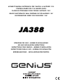 1
1
-
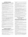 2
2
-
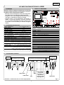 3
3
-
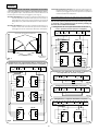 4
4
-
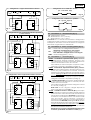 5
5
-
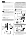 6
6
-
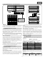 7
7
-
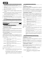 8
8
-
 9
9
-
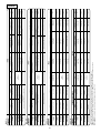 10
10
-
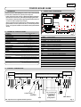 11
11
-
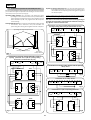 12
12
-
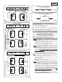 13
13
-
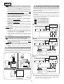 14
14
-
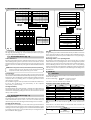 15
15
-
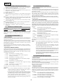 16
16
-
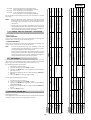 17
17
-
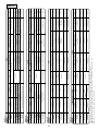 18
18
-
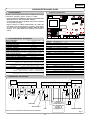 19
19
-
 20
20
-
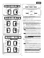 21
21
-
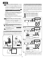 22
22
-
 23
23
-
 24
24
-
 25
25
-
 26
26
-
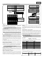 27
27
-
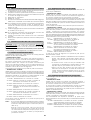 28
28
-
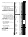 29
29
-
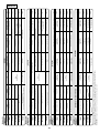 30
30
-
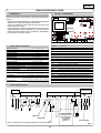 31
31
-
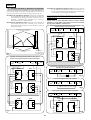 32
32
-
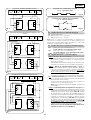 33
33
-
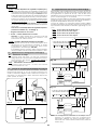 34
34
-
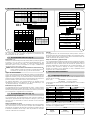 35
35
-
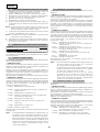 36
36
-
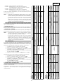 37
37
-
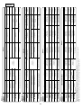 38
38
-
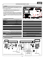 39
39
-
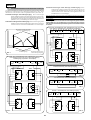 40
40
-
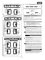 41
41
-
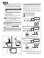 42
42
-
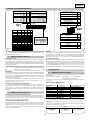 43
43
-
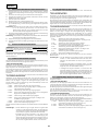 44
44
-
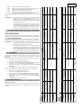 45
45
-
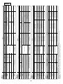 46
46
-
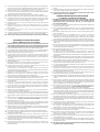 47
47
-
 48
48


en otros idiomas
- français: Genius JA388 Mode d'emploi
- italiano: Genius JA388 Istruzioni per l'uso
- English: Genius JA388 Operating instructions
- Deutsch: Genius JA388 Bedienungsanleitung
Artículos relacionados
-
Genius JA592 Use And Installation Instructions
-
-
-
-
-
-
-
-
Genius JA574 Instrucciones de operación
-