
A
Обзор оборудования
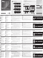
Передняя панель CE611L
1
Контакт заземления
2
Последовательный порт
RS-232
3
Кнопка обновления МП
4
Выходной аудиопорт
5
Входной аудиопорт
6
Индикатор соединения
7
Индикатор питания
Задняя панель CE611L
8
Разъем питания
9
Выходной порт HDBaseT
10
Входной порт DVI
11
Порт USB (типа B)
Передняя панель CE611R
1
Контакт заземления
2
Последовательный порт RS-232
3
Кнопка обновления МП
4
Выходной аудиопорт
5
Входной аудиопорт
6
Индикатор видеовыхода
7
Индикатор соединения
8
Индикатор питания
Задняя панель CE611R
9
Разъем питания
10
Входной порт HDBaseT
11
Выходной порт DVI
12
Порты USB (типа A)
B
Установка оборудования
Убедитесь, что все подключаемое оборудование выключено, а
затем, руководствуясь схемой установки, выполните следующую
процедуру безопасной установки устройств CE611.
1
Заземлите устройство CE611L, подсоединив один конец
заземляющего провода к контакту заземления на устройстве, а
другой конец к подходящему заземленному объекту. Выполните
ту же операцию для CE611R.
Примечание: Не пропускайте это действие. Надлежащее
заземление помогает предотвратить повреждение
устройств из-за перепадов напряжения или
разрядов статического электричества.
2
Подключите входной и выходной аудиопорты на CE611L к локальному
компьютеру с помощью кабелей микрофона и динамиков.
3
Подключите порт USB Type-B на CE611L к порту USB Type-A
локального компьютера с помощью кабеля USB.
4
Подключите входной порт DVI на CE611L к локальному
компьютеру.
5
Подключите выходной порт HDBaseT на CE611L к входному
порту HDBaseT на CE611R с помощью кабеля Cat 6/ATEN
2L-2910 для поддержки разрешений вплоть до 1920x1200 /
1600x1200.
6
Подключите один из прилагаемых адаптеров питания к
источнику питания, а затем подключите кабель адаптера
питания к гнезду питания на CE611L.
7
Подключите монитор DVI к выходному порту DVI на CE611R с
помощью кабеля DVI.
8
Подключите USB-устройства (мышь, клавиатура и т.д.) к USB-
портам на CE611R.
9
Подключите микрофон и динамики к соответствующим
аудиопортам на CE611R.
10
Подключите второй адаптер питания к источнику питания, а затем
подключите кабель адаптера питания к гнезду питания на CE611R.
11
Для удаленного управления компьютером с помощью команд
RS-232 подсоедините последовательный порт компьютера к
последовательному порту RS-232 на CE611L. Затем подключите
Повторитель CE611 Mini USB DVI HDBaseT KVM
www.aten.com
аппаратный контроллер или ПК (с установленным программным
контроллером) к порту RS-232 на CE611R.
Эксплуатация
Светодиодные индикаторы
Индикатор Индикация Описание
Питание
Вкл Устройство включено.
Выкл Устройство выключено.
Соединение
Вкл
Имеется соединение между
устройствами CE611L и CE611R.
Выкл
Отсутствует соединение между
устройствами CE611L и CE611R.
Видеовыход
Вкл Видео отображается.
Выкл Отображение видео невозможно.
Примечание: Индикатор видеовыхода имеется только на CE611R.
A
Revisione Hardware
Vista anteriore CE611L
1
Terminale di messa a terra
2
Porta seriale RS-232
3
Interruttore aggiornamento
fi rmware
4
Porta Audio Out
5
Porta Audio In
6
Link LED
7
LED accensione
Vista posteriore CE611L
8
Connettore d'alimentazione
9
Porta HDBaseT Out
10
Porta DVI In
11
Porta USB Tipo-B
Vista anteriore CE611R
1
Terminale di messa a terra
2
Porta seriale RS-232
3
Interruttore aggiornamento fi rmware
4
Porta Audio Out
5
Porta Audio In
6
LED Video Out
7
Link LED
8
LED accensione
Vista posteriore CE611R
9
Connettore d'alimentazione
10
Porta HDBaseT In
11
Porta DVI Out
12
Porte USB Tipo-A
B
Installazione dell'hardware
Assicurarsi che tutte le apparecchiature da collegare siano spente, quindi
usare lo scherma di installazione e seguire i passaggi per installare le unità
CE611 in modo sicuro.
1
Usare un cavo per la messa a terra per collegare a massa l'unità CE611L
collegando un'estremità all'unità e l'altra estremità del cavo a un oggetto
collegato a terra adatto. Eseguire la stessa operazione per l'unità CE611R.
Nota: Non saltare questo passaggio. La messa a terra adeguata aiuta a
prevenire danni alle unità dovuti a sovraccarico o elettricità statica.
2
Collegare le porte Audio In e Audio Out CE611L a un computer locale
usando un cavo per microfono o altoparlante.
3
Collegare la porta USB di tipo A del CE611L alla porta USB di tipo A
del computer locale usando un cavo USB.
4
Collegare la porta DVI del CE611L al computer locale.
5
Collegare la porta HDBaseT Out del CE611L alla porta HDBaseT In del
CE611R usando un cavo Cat 6/ATEN 2L-2910 per una risoluzione fi no
a 1920 x 1200/1600 x 1200.
6
Inserire uno degli adattatori di alimentazione in dotazione in una fonte
di alimentazione, quindi collegare il cavo di alimentazione al jack di
alimentazione del CE611L.
7
Collegare un monitor abilitato DVI alla porta DVI Out del CE611R
usando un cavo DVI.
8
Collegare i dispositivi USB (mouse, tastiera, ecc.) alle porte USB del
CE611R.
9
Inserire un microfono e gli altoparlanti nelle rispettive porte audio del
CE611R.
10
Collegare il secondo adattatore di corrente a una fonte di
alimentazione; quindi inserire il cavo di alimentazione nel jack di
alimentazione del CE611R.
11
Per controllare da remoto il computer tramite i comandi seriali RS-232,
collegare la porta seriale del computer alla porta seriale del CE611L
usando un cavo seriale RS-232, quindi collegare un controller hardware
o un PC (su cui è installato un controller software) alla porta RS-232
del CE611R.
Estensore KVM CE611 mini USB DVI HDBaseT
www.aten.com
Funzionamento
Indicatori LED
LED Display LED Descrizione
Alimentazione
Acceso L'unità è accesa.
Spento L'unità è spenta.
Link
Acceso
Le unità CE611L e CE611R sono
collegate.
Spento
Le unità CE611L e CE611R non sono
collegate.
Video Out
Acceso Il video viene riprodotto.
Spento Impossibile riprodurre il video
Nota: Il LED Video Out è disponibile solo sul CE611R.
A
Revisión del hardware
Vista frontal del CE611L
1
Terminal de conexión a tierra
2
Puerto serie RS-232
3
Interruptor de actualización de
fi rmware
4
Puerto de salida de audio
5
Puerto de audio
6
LED de conexión
7
LED de alimentación
Vista posterior del CE611L
8
Conector de alimentación
9
Puerto de salida HDBaseT
10
Puerto de entrada DVI
11
Puerto USB tipo B
Vista frontal del CE611R
1
Terminal de conexión a tierra
2
Puerto serie RS-232
3
Interruptor de actualización de
fi rmware
4
Puerto de salida de audio
5
Puerto de audio
6
LED de salida de vídeo
7
LED de conexión
8
LED de alimentación
Vista posterior del CE611R
9
Conector de alimentación
10
Puerto de entrada HDBaseT
11
Puerto de salida DVI
12
Puertos USB tipo A
B
Instalación del hardware
Asegúrese de que todos los equipos a conectar estén apagados y luego
utilice el diagrama de instalación y los siguientes pasos para instalar de
manera segura las unidades CE611.
1
Use un cable de conexión a tierra para conectar a tierra el CE611L
conectando un extremo a la unidad y el otro extremo del cable a un
objeto adecuadamente conectado a tierra. Haga lo mismo con el
CE611R.
Nota: No omita este paso. La conexión a tierra adecuada ayuda
a evitar daños a las unidades por sobrecargas de energía o
electricidad estática.
2
Conecte el puerto de entrada y salida de audio del CE611L a un
ordenador local con micrófono y cable de altavoz.
3
Conecte el puerto USB tipo B del CE611L al puerto USB tipo A del
ordenador local mediante un cable USB.
4
Conecte el puerto de entrada DVI del CE611L al ordenador local.
5
Conecte el puerto de salida HDBaseT del CE611L al puerto de entrada
HDBaseT del CE611R usando un cable Cat 6/ATEN 2L-2910 para una
resolución de hasta 1920 x 1200/1600 x 1200.
6
Enchufe uno de los adaptadores de alimentación suministrados a una
fuente de alimentación y luego conecte el cable de alimentación al
conector de alimentación del CE611L.
7
Conecte un monitor habilitado para DVI al puerto de salida DVI del
CE611R mediante un cable DVI.
8
Conecte los dispositivos USB (ratón, teclado, etc.) a los puertos USB del
CE611R.
9
Conecte un micrófono y altavoces a sus respectivos puertos de audio
en el CE611R.
10
Conecte el segundo adaptador de alimentación a una fuente de
alimentación y luego enchufe el cable de alimentación en el conector
de alimentación del CE611R.
11
Para controlar el ordenador de forma remota a través de los comandos
serie RS-232, conecte el puerto serie del ordenador al puerto serie RS-
Extensor KVM CE611 Mini USB DVI HDBaseT
www.aten.com
232 del CE611L mediante un cable serie RS-232 y luego conecte un
controlador de hardware o un PC (instalado con un controlador de
software) al puerto RS-232 del CE611R.
Funcionamiento
Indicadores LED
LED Vista de los LEDs Descripción
Alimentación
Activado La unidad está encendida.
Desactivado La unidad no está encendida.
Conexión
Activado
Las unidades CE611L y CE611R
están conectadas.
Desactivado
Las unidades CE611L y CE611R no
están conectadas.
Salida de
vídeo
Activado Aparece el vídeo.
Desactivado El vídeo no puede mostrarse
Nota: El LED de salida de vídeo sólo está disponible en el CE611R.
A
Hardware Übersicht
CE611L – Ansicht von vorne
1
Erdungsanschluss
2
Serielle RS-232 Schnittstelle
3
Schalter für Firmware-
Aktualisierung
4
Audio Ausgang
5
Audio Eingang
6
Link LED
7
Netz-LED
CE611L – Ansicht von hinten
8
Netzbuchse
9
HDBaseT Ausgang
10
DVI Eingang
11
USB Typ-B Port
CE611R – Ansicht von vorne
1
Erdungsanschluss
2
Serielle RS-232 Schnittstelle
3
Schalter für Firmware-Aktualisierung
4
Audio Ausgang
5
Audio Eingang
6
Video Ausgang LED
7
Link LED
8
Netz-LED
CE611R – Ansicht von hinten
9
Netzbuchse
10
HDBaseT-Eingang
11
DVI Ausgang
12
USB Typ-A Ports
B
Hardwareinstallation
Stellen Sie sicher, dass alle Geräte, die angeschlossen werden sollen,
ausgeschaltet sind, und verwenden Sie dann das Installationsschema und
die folgenden Schritte, um die CE611 Geräte sicher zu installieren.
1
Verwenden Sie ein Erdungskabel, um den CE611L zu erden, indem Sie
ein Ende mit dem Gerät und das andere Ende des Kabels mit einem
geeigneten geerdeten Objekt verbinden. Machen Sie dasselbe mit dem
CE611R.
Hinweis: Lassen Sie diesen Schritt nicht aus. Eine angemessene
Erdung hilft bei der Verhinderung von Geräteschäden durch
Spannungsspitzen oder statische Elektrizität.
2
Verbinden Sie den Audio Ein- und Ausgang des CE611L mit einem
lokalen Computer über ein Mikrofon und ein Lautsprecherkabel.
3
Verbinden Sie den USB Typ-B Port des CE611L mit dem USB Typ-A Port
des lokalen Computers über ein USB-Kabel.
4
Verbinden Sie den DVI-Eingang des CE611L mit dem lokalen Computer.
5
Verbinden Sie den HDBaseT-Ausgang des CE611L mit dem HDBaseT-
Eingang des CE611R über ein Cat 6/ATEN 2L-2910 Kabel mit einer
Aufl ösung von bis zu 1920 x 1200/1600 x 1200.
6
Verbinden Sie eines der mitgelieferten Netzteile mit einer Steckdose und
schließen Sie das Netzkabel am Netzanschluss des CE611L an.
7
Verbinden Sie einen DVI-fähigen Monitor mit dem DVI-Ausgang des
CE611R über ein DVI-Kabel.
8
Schließen Sie USB-Geräte (Maus, Tastatur, usw.) an die USB-Ports des
CE611R an.
9
Schließen Sie ein Mikrofon und die Lautsprecher an die entsprechenden
Audioanschlüsse am CE611R an.
10
Verbinden Sie das zweite Netzteil mit einer Steckdose und schließen Sie
das Netzkabel am Netzanschluss des CE611R an.
11
Um den Computer über serielle RS-232 Befehle fernzusteuern,
verbinden Sie den seriellen Port des Computers mit dem seriellen
RS-232 Port des CE611L über ein serielles RS-232 Kabel und verbinden
CE611 Mini USB DVI HDBaseT KVM Extender
www.aten.com
Sie dann einen Hardware Controller oder einen PC (installiert mit
einem Software Controller) mit dem RS-232 Port des CE611R.
Bedienung
LED Anzeigen
LED LED-Display Beschreibung
Betrieb
Ein Das Gerät ist eingeschaltet.
Aus Das Gerät ist nicht eingeschaltet.
Verbindung
Ein
Die CE611L und CE611R Geräte sind
verbunden.
Aus
Die CE611L und CE611R Geräte sind
nicht verbunden.
Video
Ausgang
Ein Video wird angezeigt.
Aus Video kann nicht angezeigt werden
Hinweis: Die LED für den Video-Ausgang ist nur am CE611R verfügbar.
A
Présentation du matériel
Vue de devant du CE611L
1
Prise de terre
2
Port série RS-232
3
Commutateur de mise à
niveau du microprogramme
4
Port de sortie audio
5
Port d’entrée audio
6
LED Link (Liaison)
7
LED d'alimentation
Vue de derrière du CE611L
8
Prise d'alimentation
9
Port de sortie HDBaseT
10
Port d'entrée HDMI
11
Port USB Type B
Vue de devant du CE611R
1
Prise de terre
2
Port série RS-232
3
Commutateur de mise à niveau
du microprogramme
4
Port de sortie audio
5
Port d’entrée audio
6
LED de sortie vidéo
7
LED Link (Liaison)
8
LED d'alimentation
Vue de derrière du CE611R
9
Prise d'alimentation
10
Port d’entrée HDBaseT
11
Port de sortie HDMI
12
Ports USB Type A
B
Installation matérielle
Assurez-vous que tous les équipements à connecter soient éteints, puis
utilisez le diagramme d’installation en suivant les étapes ci-dessous pour
installer correctement les unités CE611.
1
Utilisez un câble de mise à la terre pour mettre à terre le CE611L en
reliant une extrémité du câble de terre et l'autre extrémité à un objet
mis à la terre adapté. Faites pareil avec le CE611R.
Remarque : N'ignorez pas cette étape. Une mise à la terre appropriée
permet d'éviter que l'appareil ne soit endommagé par
des surtensions ou de l'électricité statique.
2
Connectez le Port d’Entrée Audio et de Sortie Audio du CE611L à un
ordinateur local en utilisant un câble de microphone et des enceintes.
3
Connectez le port USB Type B du CE611L au ports USB Type A de
l’ordinateur local en utilisant un câble USB.
4
Connectez le port d'entrée HDMI du CE611L à l’ordinateur local.
5
Connectez le port de sortie HDBaseT du CE611L au port d’entrée
HDBaseT du CE611R en utilisant un câble Cat 6/ATEN 2L-2910 pour
une résolution jusqu’à 1920 x 1200/1600 x 1200.
6
Branchez un des adaptateurs d'alimentation fournis à une source
d'alimentation, puis branchez le câble d'alimentation à la prise
d'alimentation du CE611L.
7
Connectez un écran HDMI au port de sortie HDMI du CE611R en
utilisant un câble HDMI.
8
Branchez les périphériques USB (souris, clavier, etc.) à leurs ports USB
respectifs sur le CE611R.
9
Branchez le microphone et les enceintes à leurs ports audio respectifs
sur le CE611R.
10
Branchez le second adaptateurs d'alimentation à une source
d'alimentation, puis branchez le câble d'alimentation à la prise
d'alimentation du CE611R.
11
Pour contrôler l’ordinateur à distance via les commandes sérielles RS-
232, connectez le port sériel de l’ordinateur au port sériel RS-232
du CE611L en utilisant un câble sériel RS-232, puis connectez un
contrôleur de matériel ou un PC (équipé d’un contrôleur de logiciel) au
port RS-232 du CE611R.
Extenseur KVM HDBaseT HDMI Mini USB CE611
www.aten.com
Fonctionnement
Indicateurs LED
LED
Affi chage
LED
Description
Alimentation
ACTIVÉ L’unité est active.
Éteint L’unité est inactive.
Liaison
ACTIVÉ
Les unités CE611L et CE611R sont
connectées.
Éteint
Les unités CE611L et CE611R ne sont
pas connectées.
Sortie vidéo
ACTIVÉ La vidéo est affi chée
Éteint La vidéo ne peut pas s’affi cher
Remarque : La LED de sortie vidéo est uniquement disponible sur le
CE611R.
A
Hardware Review
CE611L Front View
1
Grounding Terminal
2
RS-232 Serial Port
3
Firmware Upgrade Switch
4
Audio Out Port
5
Audio In Port
6
Link LED
7
Power LED
CE611L Rear View
8
Power Jack
9
HDBaseT Out Port
10
DVI In Port
11
USB Type-B Port
CE611R Front View
1
Grounding Terminal
2
RS-232 Serial Port
3
Firmware Upgrade Switch
4
Audio Out Port
5
Audio In Port
6
Video Out LED
7
Link LED
8
Power LED
CE611R Rear View
9
Power Jack
10
HDBaseT In Port
11
DVI Out Port
12
USB Type-A Ports
B
Hardware Installation
Make sure that all the equipment to be connected is powered off, and
then use the installation diagram and the following steps to safely install
the CE611 units.
1
Use a grounding wire to ground the CE611L by connecting one end to
the unit and the other end of the wire to a suitable grounded object.
Do the same to the CE611R.
Note: Do not omit this step. Proper grounding helps prevent damage
to the units from power surges or static electricity.
2
Connect the CE611L’s Audio In and Audio Out port to a local computer
using a microphone and a speaker cable.
3
Connect the CE611L’s USB Type-B port to the local computer’s USB
Type-A port using a USB cable.
4
Connect the CE611L’s DVI In port to the local computer.
5
Connect the CE611L’s HDBaseT Out port to the CE611R’s HDBaseT
In port using a Cat 6/ATEN 2L-2910 cable for resolution up to 1920 x
1200/1600 x 1200.
6
Plug one of the supplied power adapters into a power source, and
then plug the power cable into the CE611L’s Power Jack.
7
Connect a DVI-enabled monitor to the CE611R’s DVI Out port using a
DVI cable.
8
Plug USB devices (mouse, keyboard, etc.) into the USB ports on the
CE611R.
9
Plug a microphone and speakers into their respective audio ports on
the CE611R.
10
Plug the second power adapter into a power source, and then plug the
power cable into the CE611R’s Power Jack.
11
To remotely control the computer via RS-232 serial commands, connect
the computer’s serial port to the CE611L’s RS-232 Serial port using an
RS-232 serial cable, and then connect a hardware controller or a PC
(installed with a software controller) to the CE611R’s RS-232 port.
B
Hardware Installation
© Copyright 2018 ATEN
®
International Co., Ltd.
ATEN and the ATEN logo are trademarks of ATEN International Co., Ltd. All rights reserved. All
other trademarks are the property of their respective owners.
Part No. PAPE-1223-Q10G Printing Date: 11/2018
Mini USB DVI HDBaseT KVM Extender
Quick Start Guide
CE611
CE611 Mini USB DVI HDBaseT KVM Extender
www.aten.com
Operation
LED Indicators
LED LED Display Description
Power
On The unit is powered on.
Off The unit is not powered on.
Link
On
The CE611L and CE611R units are
connected.
Off
The CE611L and CE611R units are not
connected.
Video Out
On Video is displayed.
Off Video cannot be displayed
Note: The Video Out LED is only available on the CE611R.
Package Contents
1 CE611L Mini USB DVI HDBaseT KVM Extender (Local Unit)
1 CE611R Mini USB DVI HDBaseT KVM Extender (Remote Unit)
2 Power Adapters
1 User Instructions
Support and Documentation Notice
All information, documentation, fi rmware,
software utilities, and specifi cations
contained in this package are subject to
change without prior notifi cation by
the manufacturer.
To reduce the environmental impact of our
products, ATEN documentation and software
can be found online at
http://www.aten.com/download/
Technical Support
www.aten.com/support
이 기기는 업무용(A급) 전자파적합기기로서 판매자 또는
사용자는 이 점을 주의하시기 바라며, 가정외의 지역에
서 사용하는 것을 목적으로 합니다.
Scan for
more information
EMC Information
FEDERAL COMMUNICATIONS COMMISSION INTERFERENCE
STATEMENT:
This equipment has been tested and found to comply with the limits
for a Class A digital device, pursuant to Part 15 of the FCC Rules.
These limits are designed to provide reasonable protection against
harmful interference when the equipment is operated in a commercial
environment. This equipment generates, uses, and can radiate radio
frequency energy and, if not installed and used in accordance with
the instruction manual, may cause harmful interference to radio
communications. Operation of this equipment in a residential area
is likely to cause harmful interference in which case the user will be
required to correct the interference at his own expense.
FCC Caution: Any changes or modifi cations not expressly approved by
the party responsible for compliance could void the user's authority to
operate this equipment.
Warning: Operation of this equipment in a residential environment
could cause radio interference.
Suggestion: Shielded twisted pair (STP) cables must be used with the
unit to ensure compliance with FCC & CE standards.
This device complies with Part 15 of the FCC Rules. Operation is subject
to the following two conditions: (1) this device may not cause harmful
interference, and (2) this device must accept any interference received,
including interference that may cause undesired operation.
A
Hardware Review
4
1
2
3
7
5
6
10
8
9
11
11
9
10
12
4
1
2
3
8
5
76
CE611L Rear View
CE611L Front View
CE611R Rear View
CE611R Front View
CE611L
(Rear)
CE611L
(Front)
CE611R
(Rear)
CE611R
(Front)
4
1
1
2
3
7
8
9
11
11
10
5
6
La página se está cargando...
Transcripción de documentos
A Hardware Review CE611L Front View 1 2 3 4 Support and Documentation Notice 1 1 2 1 All information, documentation, firmware, software utilities, and specifications contained in this package are subject to change without prior notification by the manufacturer. To reduce the environmental impact of our products, ATEN documentation and software can be found online at http://www.aten.com/download/ B 6 7 5 Package Contents CE611L Rear View 1 CE611L Mini USB DVI HDBaseT KVM Extender (Local Unit) CE611R Mini USB DVI HDBaseT KVM Extender (Remote Unit) Power Adapters User Instructions Hardware Installation Technical Support www.aten.com/support CE611L (Front) CE611L (Rear) Scan for more information 6 11 8 CE611 9 10 5 EMC Information 2 CE611R Front View Mini USB DVI HDBaseT KVM Extender Quick Start Guide 3 4 11 FEDERAL COMMUNICATIONS COMMISSION INTERFERENCE STATEMENT: This equipment has been tested and found to comply with the limits for a Class A digital device, pursuant to Part 15 of the FCC Rules. These limits are designed to provide reasonable protection against harmful interference when the equipment is operated in a commercial environment. This equipment generates, uses, and can radiate radio frequency energy and, if not installed and used in accordance with the instruction manual, may cause harmful interference to radio communications. Operation of this equipment in a residential area is likely to cause harmful interference in which case the user will be required to correct the interference at his own expense. FCC Caution: Any changes or modifications not expressly approved by the party responsible for compliance could void the user's authority to operate this equipment. Warning: Operation of this equipment in a residential environment could cause radio interference. Suggestion: Shielded twisted pair (STP) cables must be used with the unit to ensure compliance with FCC & CE standards. 1 2 © Copyright 2018 ATEN® International Co., Ltd. 3 4 5 6 7 8 1 CE611R (Front) CE611R (Rear) CE611R Rear View ATEN and the ATEN logo are trademarks of ATEN International Co., Ltd. All rights reserved. All other trademarks are the property of their respective owners. Part No. PAPE-1223-Q10G 11 Printing Date: 11/2018 9 10 11 9 10 7 8 This device complies with Part 15 of the FCC Rules. Operation is subject to the following two conditions: (1) this device may not cause harmful interference, and (2) this device must accept any interference received, including interference that may cause undesired operation. 12 이 기기는 업무용(A급) 전자파적합기기로서 판매자 또는 사용자는 이 점을 주의하시기 바라며, 가정외의 지역에 서 사용하는 것을 목적으로 합니다. CE611 Mini USB DVI HDBaseT KVM Extender A Hardware Review CE611L Front View 1 2 3 4 5 6 7 B CE611R Front View Grounding Terminal RS-232 Serial Port Firmware Upgrade Switch Audio Out Port Audio In Port Link LED Power LED Grounding Terminal RS-232 Serial Port Firmware Upgrade Switch Audio Out Port Audio In Port Video Out LED Link LED Power LED 1 2 3 4 5 6 7 8 CE611L Rear View 8 CE611R Rear View 9 Power Jack 10 HDBaseT In Port 11 DVI Out Port 12 USB Type-A Ports Power Jack HDBaseT Out Port 10 DVI In Port 11 USB Type-B Port www.aten.com 9 Hardware Installation Make sure that all the equipment to be connected is powered off, and then use the installation diagram and the following steps to safely install the CE611 units. 1 Use a grounding wire to ground the CE611L by connecting one end to the unit and the other end of the wire to a suitable grounded object. Do the same to the CE611R. Note: Do not omit this step. Proper grounding helps prevent damage to the units from power surges or static electricity. 2 Connect the CE611L’s Audio In and Audio Out port to a local computer using a microphone and a speaker cable. 3 Connect the CE611L’s USB Type-B port to the local computer’s USB Type-A port using a USB cable. 4 Connect the CE611L’s DVI In port to the local computer. 5 Connect the CE611L’s HDBaseT Out port to the CE611R’s HDBaseT In port using a Cat 6/ATEN 2L-2910 cable for resolution up to 1920 x 1200/1600 x 1200. 6 7 8 9 10 11 Plug one of the supplied power adapters into a power source, and then plug the power cable into the CE611L’s Power Jack. Connect a DVI-enabled monitor to the CE611R’s DVI Out port using a DVI cable. Plug USB devices (mouse, keyboard, etc.) into the USB ports on the CE611R. Plug a microphone and speakers into their respective audio ports on the CE611R. Plug the second power adapter into a power source, and then plug the power cable into the CE611R’s Power Jack. To remotely control the computer via RS-232 serial commands, connect the computer’s serial port to the CE611L’s RS-232 Serial port using an RS-232 serial cable, and then connect a hardware controller or a PC (installed with a software controller) to the CE611R’s RS-232 port. Operation LED Indicators LED Power Link Video Out LED Display Description On The unit is powered on. Off The unit is not powered on. The CE611L and CE611R units are On connected. The CE611L and CE611R units are not Off connected. On Video is displayed. Off Video cannot be displayed Note: The Video Out LED is only available on the CE611R. Extenseur KVM HDBaseT HDMI Mini USB CE611 A Présentation du matériel Vue de devant du CE611L 1 2 3 4 5 6 7 B Vue de devant du CE611R Prise de terre Port série RS-232 Commutateur de mise à niveau du microprogramme Port de sortie audio Port d’entrée audio LED Link (Liaison) LED d'alimentation 1 2 3 4 5 6 7 8 Vue de derrière du CE611L Prise de terre Port série RS-232 Commutateur de mise à niveau du microprogramme Port de sortie audio Port d’entrée audio LED de sortie vidéo LED Link (Liaison) LED d'alimentation 8 Vue de derrière du CE611R 9 Prise d'alimentation 10 Port d’entrée HDBaseT 11 Port de sortie HDMI 12 Ports USB Type A Prise d'alimentation Port de sortie HDBaseT 10 Port d'entrée HDMI 11 Port USB Type B www.aten.com 9 Installation matérielle Assurez-vous que tous les équipements à connecter soient éteints, puis utilisez le diagramme d’installation en suivant les étapes ci-dessous pour installer correctement les unités CE611. 1 Utilisez un câble de mise à la terre pour mettre à terre le CE611L en reliant une extrémité du câble de terre et l'autre extrémité à un objet mis à la terre adapté. Faites pareil avec le CE611R. Remarque : N'ignorez pas cette étape. Une mise à la terre appropriée permet d'éviter que l'appareil ne soit endommagé par des surtensions ou de l'électricité statique. 2 Connectez le Port d’Entrée Audio et de Sortie Audio du CE611L à un ordinateur local en utilisant un câble de microphone et des enceintes. 3 Connectez le port USB Type B du CE611L au ports USB Type A de l’ordinateur local en utilisant un câble USB. 4 Connectez le port d'entrée HDMI du CE611L à l’ordinateur local. 5 Connectez le port de sortie HDBaseT du CE611L au port d’entrée HDBaseT du CE611R en utilisant un câble Cat 6/ATEN 2L-2910 pour une résolution jusqu’à 1920 x 1200/1600 x 1200. 6 7 8 9 10 11 Branchez un des adaptateurs d'alimentation fournis à une source d'alimentation, puis branchez le câble d'alimentation à la prise d'alimentation du CE611L. Connectez un écran HDMI au port de sortie HDMI du CE611R en utilisant un câble HDMI. Branchez les périphériques USB (souris, clavier, etc.) à leurs ports USB respectifs sur le CE611R. Branchez le microphone et les enceintes à leurs ports audio respectifs sur le CE611R. Branchez le second adaptateurs d'alimentation à une source d'alimentation, puis branchez le câble d'alimentation à la prise d'alimentation du CE611R. Pour contrôler l’ordinateur à distance via les commandes sérielles RS232, connectez le port sériel de l’ordinateur au port sériel RS-232 du CE611L en utilisant un câble sériel RS-232, puis connectez un contrôleur de matériel ou un PC (équipé d’un contrôleur de logiciel) au port RS-232 du CE611R. Fonctionnement Indicateurs LED Affichage LED ACTIVÉ Éteint LED Alimentation ACTIVÉ Liaison Éteint ACTIVÉ Éteint Sortie vidéo Description L’unité est active. L’unité est inactive. Les unités CE611L et CE611R sont connectées. Les unités CE611L et CE611R ne sont pas connectées. La vidéo est affichée La vidéo ne peut pas s’afficher Remarque : La LED de sortie vidéo est uniquement disponible sur le CE611R. CE611 Mini USB DVI HDBaseT KVM Extender A Hardware Übersicht CE611L – Ansicht von vorne 1 2 3 4 5 6 7 B CE611R – Ansicht von vorne Erdungsanschluss Serielle RS-232 Schnittstelle Schalter für FirmwareAktualisierung Audio Ausgang Audio Eingang Link LED Netz-LED CE611L – Ansicht von hinten Netzbuchse HDBaseT Ausgang 10 DVI Eingang 11 USB Typ-B Port 8 9 www.aten.com 1 2 3 4 5 6 7 8 Erdungsanschluss Serielle RS-232 Schnittstelle Schalter für Firmware-Aktualisierung Audio Ausgang Audio Eingang Video Ausgang LED Link LED Netz-LED CE611R – Ansicht von hinten Netzbuchse HDBaseT-Eingang 11 DVI Ausgang 12 USB Typ-A Ports 9 10 Hardwareinstallation Stellen Sie sicher, dass alle Geräte, die angeschlossen werden sollen, ausgeschaltet sind, und verwenden Sie dann das Installationsschema und die folgenden Schritte, um die CE611 Geräte sicher zu installieren. 1 Verwenden Sie ein Erdungskabel, um den CE611L zu erden, indem Sie ein Ende mit dem Gerät und das andere Ende des Kabels mit einem geeigneten geerdeten Objekt verbinden. Machen Sie dasselbe mit dem CE611R. Hinweis: Lassen Sie diesen Schritt nicht aus. Eine angemessene Erdung hilft bei der Verhinderung von Geräteschäden durch Spannungsspitzen oder statische Elektrizität. 2 Verbinden Sie den Audio Ein- und Ausgang des CE611L mit einem lokalen Computer über ein Mikrofon und ein Lautsprecherkabel. 3 Verbinden Sie den USB Typ-B Port des CE611L mit dem USB Typ-A Port des lokalen Computers über ein USB-Kabel. 4 Verbinden Sie den DVI-Eingang des CE611L mit dem lokalen Computer. 5 6 7 8 9 10 11 Verbinden Sie den HDBaseT-Ausgang des CE611L mit dem HDBaseTEingang des CE611R über ein Cat 6/ATEN 2L-2910 Kabel mit einer Auflösung von bis zu 1920 x 1200/1600 x 1200. Verbinden Sie eines der mitgelieferten Netzteile mit einer Steckdose und schließen Sie das Netzkabel am Netzanschluss des CE611L an. Verbinden Sie einen DVI-fähigen Monitor mit dem DVI-Ausgang des CE611R über ein DVI-Kabel. Schließen Sie USB-Geräte (Maus, Tastatur, usw.) an die USB-Ports des CE611R an. Schließen Sie ein Mikrofon und die Lautsprecher an die entsprechenden Audioanschlüsse am CE611R an. Verbinden Sie das zweite Netzteil mit einer Steckdose und schließen Sie das Netzkabel am Netzanschluss des CE611R an. Um den Computer über serielle RS-232 Befehle fernzusteuern, verbinden Sie den seriellen Port des Computers mit dem seriellen RS-232 Port des CE611L über ein serielles RS-232 Kabel und verbinden Sie dann einen Hardware Controller oder einen PC (installiert mit einem Software Controller) mit dem RS-232 Port des CE611R. Bedienung LED Anzeigen LED Betrieb LED-Display Ein Aus Ein Verbindung Aus Video Ausgang Ein Aus Beschreibung Das Gerät ist eingeschaltet. Das Gerät ist nicht eingeschaltet. Die CE611L und CE611R Geräte sind verbunden. Die CE611L und CE611R Geräte sind nicht verbunden. Video wird angezeigt. Video kann nicht angezeigt werden Hinweis: Die LED für den Video-Ausgang ist nur am CE611R verfügbar. Extensor KVM CE611 Mini USB DVI HDBaseT A Revisión del hardware Vista frontal del CE611L 1 2 3 4 5 6 7 Terminal de conexión a tierra Puerto serie RS-232 Interruptor de actualización de firmware Puerto de salida de audio Puerto de audio LED de conexión LED de alimentación Vista posterior del CE611L Conector de alimentación 9 Puerto de salida HDBaseT 10 Puerto de entrada DVI 11 Puerto USB tipo B 8 www.aten.com B Vista frontal del CE611R 1 2 3 4 5 6 7 8 Terminal de conexión a tierra Puerto serie RS-232 Interruptor de actualización de firmware Puerto de salida de audio Puerto de audio LED de salida de vídeo LED de conexión LED de alimentación Vista posterior del CE611R Conector de alimentación Puerto de entrada HDBaseT 11 Puerto de salida DVI 12 Puertos USB tipo A 9 10 Instalación del hardware Asegúrese de que todos los equipos a conectar estén apagados y luego utilice el diagrama de instalación y los siguientes pasos para instalar de manera segura las unidades CE611. 1 Use un cable de conexión a tierra para conectar a tierra el CE611L conectando un extremo a la unidad y el otro extremo del cable a un objeto adecuadamente conectado a tierra. Haga lo mismo con el CE611R. Nota: No omita este paso. La conexión a tierra adecuada ayuda a evitar daños a las unidades por sobrecargas de energía o electricidad estática. 2 Conecte el puerto de entrada y salida de audio del CE611L a un ordenador local con micrófono y cable de altavoz. 3 Conecte el puerto USB tipo B del CE611L al puerto USB tipo A del ordenador local mediante un cable USB. 4 Conecte el puerto de entrada DVI del CE611L al ordenador local. 5 6 7 8 9 10 11 Conecte el puerto de salida HDBaseT del CE611L al puerto de entrada HDBaseT del CE611R usando un cable Cat 6/ATEN 2L-2910 para una resolución de hasta 1920 x 1200/1600 x 1200. Enchufe uno de los adaptadores de alimentación suministrados a una fuente de alimentación y luego conecte el cable de alimentación al conector de alimentación del CE611L. Conecte un monitor habilitado para DVI al puerto de salida DVI del CE611R mediante un cable DVI. Conecte los dispositivos USB (ratón, teclado, etc.) a los puertos USB del CE611R. Conecte un micrófono y altavoces a sus respectivos puertos de audio en el CE611R. Conecte el segundo adaptador de alimentación a una fuente de alimentación y luego enchufe el cable de alimentación en el conector de alimentación del CE611R. Para controlar el ordenador de forma remota a través de los comandos serie RS-232, conecte el puerto serie del ordenador al puerto serie RS- 232 del CE611L mediante un cable serie RS-232 y luego conecte un controlador de hardware o un PC (instalado con un controlador de software) al puerto RS-232 del CE611R. Funcionamiento Indicadores LED LED Alimentación Vista de los LEDs Activado Desactivado Activado Conexión Desactivado Salida de vídeo Activado Desactivado Descripción La unidad está encendida. La unidad no está encendida. Las unidades CE611L y CE611R están conectadas. Las unidades CE611L y CE611R no están conectadas. Aparece el vídeo. El vídeo no puede mostrarse Nota: El LED de salida de vídeo sólo está disponible en el CE611R. Estensore KVM CE611 mini USB DVI HDBaseT A Revisione Hardware Vista anteriore CE611L 1 2 3 4 5 6 7 Terminale di messa a terra Porta seriale RS-232 Interruttore aggiornamento firmware Porta Audio Out Porta Audio In Link LED LED accensione B Vista anteriore CE611R 1 2 3 4 5 6 7 8 Terminale di messa a terra Porta seriale RS-232 Interruttore aggiornamento firmware Porta Audio Out Porta Audio In LED Video Out Link LED LED accensione Vista posteriore CE611L Vista posteriore CE611R Connettore d'alimentazione 9 Porta HDBaseT Out 10 Porta DVI In 11 Porta USB Tipo-B Connettore d'alimentazione 10 Porta HDBaseT In 11 Porta DVI Out 12 Porte USB Tipo-A 8 www.aten.com 9 Installazione dell'hardware Assicurarsi che tutte le apparecchiature da collegare siano spente, quindi usare lo scherma di installazione e seguire i passaggi per installare le unità CE611 in modo sicuro. 1 Usare un cavo per la messa a terra per collegare a massa l'unità CE611L collegando un'estremità all'unità e l'altra estremità del cavo a un oggetto collegato a terra adatto. Eseguire la stessa operazione per l'unità CE611R. Nota: Non saltare questo passaggio. La messa a terra adeguata aiuta a prevenire danni alle unità dovuti a sovraccarico o elettricità statica. 2 Collegare le porte Audio In e Audio Out CE611L a un computer locale usando un cavo per microfono o altoparlante. 3 Collegare la porta USB di tipo A del CE611L alla porta USB di tipo A del computer locale usando un cavo USB. 4 Collegare la porta DVI del CE611L al computer locale. 5 Collegare la porta HDBaseT Out del CE611L alla porta HDBaseT In del CE611R usando un cavo Cat 6/ATEN 2L-2910 per una risoluzione fino a 1920 x 1200/1600 x 1200. 6 7 8 9 10 11 Inserire uno degli adattatori di alimentazione in dotazione in una fonte di alimentazione, quindi collegare il cavo di alimentazione al jack di alimentazione del CE611L. Collegare un monitor abilitato DVI alla porta DVI Out del CE611R usando un cavo DVI. Collegare i dispositivi USB (mouse, tastiera, ecc.) alle porte USB del CE611R. Inserire un microfono e gli altoparlanti nelle rispettive porte audio del CE611R. Collegare il secondo adattatore di corrente a una fonte di alimentazione; quindi inserire il cavo di alimentazione nel jack di alimentazione del CE611R. Per controllare da remoto il computer tramite i comandi seriali RS-232, collegare la porta seriale del computer alla porta seriale del CE611L usando un cavo seriale RS-232, quindi collegare un controller hardware o un PC (su cui è installato un controller software) alla porta RS-232 del CE611R. Funzionamento Indicatori LED LED Alimentazione Link Video Out Display LED Descrizione Acceso L'unità è accesa. Spento L'unità è spenta. Le unità CE611L e CE611R sono Acceso collegate. Le unità CE611L e CE611R non sono Spento collegate. Acceso Il video viene riprodotto. Spento Impossibile riprodurre il video Nota: Il LED Video Out è disponibile solo sul CE611R. Повторитель CE611 Mini USB DVI HDBaseT KVM A Обзор оборудования Передняя панель CE611L 1 2 3 4 5 6 7 Контакт заземления Последовательный порт RS-232 Кнопка обновления МП Выходной аудиопорт Входной аудиопорт Индикатор соединения Индикатор питания Задняя панель CE611L Разъем питания Выходной порт HDBaseT 10 Входной порт DVI 11 Порт USB (типа B) 8 9 B Передняя панель CE611R 1 2 3 4 5 6 7 8 Контакт заземления Последовательный порт RS-232 Кнопка обновления МП Выходной аудиопорт Входной аудиопорт Индикатор видеовыхода Индикатор соединения Индикатор питания Задняя панель CE611R Разъем питания Входной порт HDBaseT 11 Выходной порт DVI 12 Порты USB (типа A) 9 10 www.aten.com Установка оборудования Убедитесь, что все подключаемое оборудование выключено, а затем, руководствуясь схемой установки, выполните следующую процедуру безопасной установки устройств CE611. 1 Заземлите устройство CE611L, подсоединив один конец заземляющего провода к контакту заземления на устройстве, а другой конец к подходящему заземленному объекту. Выполните ту же операцию для CE611R. Примечание: Не пропускайте это действие. Надлежащее заземление помогает предотвратить повреждение устройств из-за перепадов напряжения или разрядов статического электричества. 2 Подключите входной и выходной аудиопорты на CE611L к локальному компьютеру с помощью кабелей микрофона и динамиков. 3 Подключите порт USB Type-B на CE611L к порту USB Type-A локального компьютера с помощью кабеля USB. 4 Подключите входной порт DVI на CE611L к локальному компьютеру. 5 6 7 8 9 10 11 Подключите выходной порт HDBaseT на CE611L к входному порту HDBaseT на CE611R с помощью кабеля Cat 6/ATEN 2L-2910 для поддержки разрешений вплоть до 1920x1200 / 1600x1200. Подключите один из прилагаемых адаптеров питания к источнику питания, а затем подключите кабель адаптера питания к гнезду питания на CE611L. Подключите монитор DVI к выходному порту DVI на CE611R с помощью кабеля DVI. Подключите USB-устройства (мышь, клавиатура и т.д.) к USBпортам на CE611R. Подключите микрофон и динамики к соответствующим аудиопортам на CE611R. Подключите второй адаптер питания к источнику питания, а затем подключите кабель адаптера питания к гнезду питания на CE611R. Для удаленного управления компьютером с помощью команд RS-232 подсоедините последовательный порт компьютера к последовательному порту RS-232 на CE611L. Затем подключите аппаратный контроллер или ПК (с установленным программным контроллером) к порту RS-232 на CE611R. Эксплуатация Светодиодные индикаторы Индикатор Питание Соединение Видеовыход Индикация Вкл Выкл Вкл Выкл Вкл Выкл Описание Устройство включено. Устройство выключено. Имеется соединение между устройствами CE611L и CE611R. Отсутствует соединение между устройствами CE611L и CE611R. Видео отображается. Отображение видео невозможно. Примечание: Индикатор видеовыхода имеется только на CE611R.-
 1
1
-
 2
2


ATEN CE611 Guía de inicio rápido
- Tipo
- Guía de inicio rápido
- Este manual también es adecuado para
en otros idiomas
- français: ATEN CE611 Guide de démarrage rapide
- italiano: ATEN CE611 Guida Rapida
- English: ATEN CE611 Quick start guide
- Deutsch: ATEN CE611 Schnellstartanleitung
- русский: ATEN CE611 Инструкция по началу работы
- português: ATEN CE611 Guia rápido
- polski: ATEN CE611 Skrócona instrukcja obsługi
- 日本語: ATEN CE611 クイックスタートガイド
- Türkçe: ATEN CE611 Hızlı başlangıç Kılavuzu
Artículos relacionados
-
ATEN CE624 Guía de inicio rápido
-
-
ATEN VE1830 Guía de inicio rápido
-
ATEN CE820-AT-U Guía de inicio rápido
-
ATEN CE620 Guía de inicio rápido
-
ATEN CE620 USB DVI HDBaseT 2.0 KVM Extender Guía del usuario
-
ATEN UCE32100 Guía de inicio rápido
-
ATEN CE920L Guía del usuario
-
ATEN CE924 Guía de inicio rápido
-