Proctor Silex 84131 El manual del propietario
- Categoría
- Barbacoas
- Tipo
- El manual del propietario

STOP! TO PREVENT DAMAGING YOUR GRILL, READ THiS
MANUAL FIRST FOR iMPORTANT UNPACKING AND
ASSEMBLY iNSTRUCTiONS!
m
|
Type Gas Gri
Assembly and Operation Manual
Consumer Affairs: 1-800-851-8900
FOR OUTDOOR USE ONLY
Hamilton Beach Brands, Inc.
Glen Allen, Virginia 23060
8402081 O0

BEFORE YOU BEGIN
Message to Our Users .............................................................................................................. 3
Safety Symbols ......................................................................................................................... 3
Installation/Safety Precautions ................................................................................................. 4
Propane and Gas Warning ....................................................................................................... 4
Grill Parts List ............................................................................................................................ 5
Grill Parts Diagram .................................................................................................................... 7
ASSEMBLY
Before the Assembly ................................................................................................................ 8
Assembly Steps ...................................................................................................................... 11
POST-ASSEMBLY
Gas Connection ...................................................................................................................... 19
Leak Testing ............................................................................................................................ 23
Final Installation Checklist ...................................................................................................... 24
Grill Lighting Instruction .......................................................................................................... 24
Operating Instruction .............................................................................................................. 26
Safety Tips .............................................................................................................................. 28
Care and Maintenance ........................................................................................................... 28
Troubleshooting ...................................................................................................................... 30
Food Safety ............................................................................................................................ 31
Grill Storage ............................................................................................................................ 31
,, If you smell gas:
1. Shut off gas to the grill.
2. Extinguish any open flames immediately.
3. Open the grill lid.
4. If the odor persists, keep away from the grill and call your gas supplier or your
fire department immediately.
• Do not store or use gasoline or other flammable items in the vicinity of this grill or
any other appliance.
• Any LP cylinder that is not connected for use should not be stored in the vicinity of
this grill or any other appliance.

MESSAGE TO OUR USERS
Thank you for your purchase of our Gas Grill. We sincerely wish you wilt enjoy using our fine
products.
,, Please read this user's manual in its entirety before using the grill.
,, Please contact Consumer Affairs if you have any questions.
,, Please read this user's manual carefully. Failure to follow the provided instruction can
result in serious bodily injury and/or property damage.
,, Some parts of this grill may have sharp edges. Please wear suitable protective gloves.
IMPORTANT: This grill is intended for outdoor use only and is not intended to be installed in
or on recreational vehicles or boats.
NOTE TO INSTALLER: Leave this user's manual with the customer after delivery and/or
installation.
NOTE TO CONSUMER: Leave this user's manual in a convenient place for future reference.
SAFETY SYMBOLS
The symbols listed here are being used throughout this manual. Please pay
special attention to them. The meaning of each of the symbols is listed here:
This symbol indicates an imminently hazardous
situation which wilt result in death or serious bodily
injury if not followed properly.
This symbol indicates serious bodily injury may result
if the instructions are not followed.
This symbol indicates a hazardous situation which
may result in minor or moderate bodily injury if the
instructions are not properly followed.
3

CALiFORNiA PROPOSiTiON 65
1. Combustion by=products produced when using this product contain chemicals
known to the State of California to cause cancer, birth defects, and other
reproductive harm.
2. This product contains chemicals, including lead and lead compounds, known to
the State of California to cause cancer, birth defects, or other reproductive harm.
Wash your hands after handling this product.
INSTALLATION/SAFETY PRECAUTIONS
READ THiS SECTION FIRST BEFORE iNSTALLiNG THE GRILL
,, This grill is designed to use LP gas only. The regulator supplied by Hamilton Beach must
be used.
,, The installation of this appliance must conform with local codes or, in the absence of local
codes, with either the National Fuel Gas Code, ANSI Z223.1/NFPA 54, or CAN/CSA
B149.1, Natural Gas and Propane Installation Code, or CAN/CSA B149.2, Propane
Storage and Handling Code.
,, The LP gas supply tank is to be constructed and marked in accordance with the
specifications for LP gas tanks of the U.S. Department of Transportation (DOT} or the
National Standard of Canada, CAN/CSA=B339, Tanks, Spheres, and Tubes for the
Transportation of Dangerous Goods.
,, If an external electrical source is utilized, the outdoor cooking gas appliance, when installed,
must be electrically grounded in accordance with local codes or, in the absence of local
codes, with the National Electrical Code, ANSI/NFPA 70, or the Canadian Electrical
Code, CSA C22.1. Keep the power cord of the motor away from the hot surfaces of the
grill while in use. Remove and store the motor in a dry place when not in use.
,, This grill is safety-certified for use in the United States and Canada only. Never modify
to use in other places. Modification may cause serious bodily injury or property damage.
Hamilton Beach is not responsible for any modifications, and all warranties wilt be void.
TOTAL GAS CONSUMPTION:
Total gas consumption (per hour) of OG01 grill with all burners on HI:
3 Main burners x 11,000 Btu/hr each: Total 33,000 Btu/h

GRILL PARTS LiST
KEY DESCRIPTION QUANTITY PART NUMBER
1 Lid 1 990130100
2 Temperature Gauge 1 990127300
3 Bezel, Temperature Gauge 1 990127400
4 Logo Plate 1 990130500
5 Lid Handle 1 990127500
6 Rotate Rod, Lid 2 990127600
7 Bezel, Rotate Rod 2 990127700
8 Firebox 1 990129900
9 Left-Side Shelf 1 990127800
10 Warming Rack 1 990127900
11 Cooking Grate 2 990128000
12 Heat Diffuser (Flame Tamer) 3 990128100
13 Main Burner 3 990128200
14 Manifold, Main Burner 1 990128300
15 Gas Valve, Main Burner 3 990128400
16 Regulator 1 990129700
17 Control Panel 1 990130200
18 Control Knob 3 990128500
19 Rear Panel 1 990139500
20 Right-Side Shelf 1 990128700
21 Grease Cup Clip 1 990135000
22 Grease Cup 1 990135100
23 Cart Frame 1 990130400
24 Tank Hold Chain 1 990128800
25 Left Panel 1 990130300
26 Match Holder Bracket (Nylon 1 990137000
Knot)
5

GRILL PARTS LiST
KEY DESCRIPTION QUANTITY PART NUMBER
27 Match Holder 1 990137100
28 Tank Baffle 1 990139600
29 Right Panel 1 990135600
30 Front Panel 1 990130000
31 Bottom Shelf 1 990129800
32 Standard Caster 2 990128900
33 Foot 2 990129000

GRILL PARTS DIAGRAM
@
®
7

BEFORE THE ASSEMBLY
READ AND FOLLOW THE iNSTRUCTiONS BELOW TO CORRECTLY UNPACK
GRILL PARTS FROM SHiPPiNG BOX.
STEP 1"
1. Open shipping box by slicing down its edges with a box cutter. Take out all the parts out of
protective styrofoam as shown in Fig. A. Remove all parts from plastic bags.
Grill Head
Bottom Shelf
Left and Right
Panels
Grill Head
Warming Rack
Front Panel
Tank Baffle _%
Cart Frame
Styrofoam
Fig. A

BEFORE THE ASSEMBLY
STEP 2:
1. Open grill lid, and take out the small boxes packed within the grill head. Remove all packing
materials and remove all parts from boxes as shown in Fig. B below.
Grill Head
Cooking Grids
Left and Right
Styrofoam Shelves
Cardboard
Heat Diffusers
Box
Tank Hold Chain
Grease Cup Clip _ _ ,_
and Grease Cup '_i__"_
PositioningGage _ Feet
Casters
.... _ Hardware Pack
Fig. B
9

BEFORE THE ASSEMBLY
PLEASE READ AND FOLLOW THESE iNSTRUCTiONS CAREFULLY
STEP BY STEP
Tools Required:
,, #2 Phillips screwdriver (not provided)
,, The following hardware is provided in the blister pack:
M4 x 10 Screws (16) M5 x 10 Screws (5) M6 x 26 Screws (2)
M6 x 13 Screws (16)
©
Flat M6 Washer (4) M6 Compression Washer (2)
Wrench (1)
M4 Nut (4)
©
Match Holder Bracket (Nylon Knot) (1) Match Holder (1)
©
10

ASSEMBLY STEPS
STEP 1" Bottom Shelf
1. Turn bottom shelf upside down. Attach the two (2) standard casters to right side of bottom
shelf with eight (8) M6 x 13 screws as shown in Fig. 1.
2. Screw one foot into the bottom shelf by hand, using the positioning gage to determine the
proper depth as shown in Fig. 1. Once the foot is screwed in to the proper depth, hold it in
place while tightening the nut to the bottom shelf with the provided wrench, as also shown in
Fig. 1. This will secure the foot in place.
3. Repeat Step 2 with the other foot.
Positioning Gage (Packed with feet)
Wrench
Fig. 1
11

ASSEMBLY STEPS
STEP 2: Cart
1. Turn bottom shelf right side up as shown in Fig. 2.
2. Attach front panel with the correct direction marked "UP" to front of bottom shelf with three
(3) M5 x 10 screws as shown in Fig. 2.
3. Attach left panel (marked "L') to front panel with three (3) M4 x 10 screws as shown in Fig. 2.
Attach left panel to bottom shelf with one (1) M5 × 10 screw as shown in Fig. 2.
4. Attach right panel (marked "R") to front panel with three (3) M4 × 10 screws. Attach right
panel to bottom shelf with one (1) M5 x 10 screw as shown in Fig. 2.
Fig. 2
12

ASSEMBLY STEPS
STEP 3: Cart Frame
1. To attach cart frame, align cart frame with side panels as shown in Fig. 3.
2. Attach cart frame to left panel and right panel with six (6) M4 x 10 screws (3 on each side) as
shown in Fig. 3.
3. Attach cart frame to bottom shelf with two (2) M6 x 13 screws (1 on each side) as shown in
Fig. 3.
4. Position the ends of the tank baffle so that the holes in the ends of the baffle are aligned with
the holes in the side panels, then attach the tank baffle to the left and right panel with four (4)
M4 x 10 screws (2 on each side) from the outside to the inside, and four (4) M4 nuts on the
inside (2 on each side), all as shown in Fig. 3.
Fig. 3
13

ASSEMBLY STEPS
STEP 4: Grill Head to Cart
1. Remove the tie wraps securing regulator hose to underside of grill head.
2. Carefully lower the grill head onto the cart. Make sure the regulator hose is hanging outside
the cart. Attach head to cart with two (2) M6 x 13 screws and two (2) M6 flat washer in the
front; two (2) M6 x 26 screws in the back as shown in Fig. 4.
0
Note regulator hose is routed
outside of cart.
Fig. 4
14

ASSEMBLY STEPS
STEP 5: Side Shelves
Attach the right shelf to firebox as follows:
1. Locate side shelf onto support brackets located on side of the fire box as shown in Fig. 5a
and remove the cooking grids from the firebox.
2. From the outside of the firebox, attach the right shelf (marked "R") with two (2) M6 x 13
screws and two (2) M6 flat washers as shown in Fig. 5b.
3. From the inside of the firebox, attach the right shelf with two (2) M6 x 13 screws and two (2)
M6 compression washers as shown in Fig. 5c.
4. Repeat above Steps 1-3 for the left shelf (marked "L').
@ @
®
Support Brackets
Fig. 5a
15

ASSEMBLY STEPS
STEP 5: Side Shelves
j_J
©
• •
. ///
Fig. 5c
16

ASSEMBLY STEPS
STEP 6: Nylon Knot
1. Insert the nylon knot to the hole on the right side panel; then put the match holder in it and
capture it as shown in Fig. 6.
(4 • •
i/ ',,
/ 7,uJ L') \
i
i
f
\
STEP 7: Grease Cup
1. Place grease cup into grease cup clip and hang grease cup clip from bottom of firebox and
as shown in Fig. 7.
i
i
i
/
I
i \
i'
i
,\ /i
17

ASSEMBLY STEPS
STEP 8: Cooking Grates
1. Place heat diffusers over burners by inserting tabs into slots in front and back of the firebox
as shown in Fig. 8b and Fig. 8c.
2. Place cooking grates onto grate rests as shown in Fig. 8a.
3. Insert warming rack at the top of the firebox as shown as shown in Fig. 8a.
/
/
,/
®
®
Fig. 8a
\
Front of heat
diffusers
\
Rear of heat
diffusers
View from rear of the firebox
Fig. 8c
18

GAS CONNECTION
ONLY USE THE REGULATOR AND HOSE ASSEMBLY PROVIDED WiTH THiS
GRILL. REPLACEMENT PRESSURE REGULATORS AND HOSE ASSEMBLIES
MUST BE THOSE SUPPLIED BY THE MANUFACTURER.
This is an LP (Liquefied Petroleum Gas) configured grill. Do not attempt to use a natural gas
supply unless the grill has been reconfigured for natural gas use.
The installation of this appliance must conform with local codes or, in the absence of local
codes, with either the National Fuel Gas Code, ANSI Z223.1/NFPA 54, or CAN/CSA B149.1,
Natural Gas and Propane Installation Code, or CAN/CSA B149.2, Propane Storage and
Handling Code.
LP TANK REQUIREMENTS -
THE LP TANK USED WiTH YOUR GRILL MUST MEET THE FOLLOWING:
1, Measurement: 12" (30.5=cm) diameter x 18" (45.7-cm) tall.
2. Maximum capacity: 20 Ibs. (9 kg).
3, Constructed and marked in accordance with the specification for LP gas cylinders of the U.S.
Department of Transportation (DOT) or the National Standard of Canada, CAN/CSA=B339,
Cylinders, Spheres, and Tubes for the Transportation of Dangerous Goods. See LP tank collar
for marking.
4, Tank must be oriented to provide proper vapor withdrawal, as shown in Fig, 9.
5. Includes a collar to protect the tank valve.
6, Has no dents or rust. A dented or rusty LP tank may be hazardous and should be checked
by your supplier.
7, Provides a shut=off valve terminating in an LP gas tank valve outlet specified, as applicable,
for connection type QCC1 in the standard for compressed gas tank valve outlet and inlet
connection ANSI/CGA V-1.
8, Other tanks may be acceptable for use with your grill provided they are compatible with the
tank retention means in Fig, 9.
LP TANK VALVE USED MUST MEET THE FOLLOWING:
1, Have type I outlet compatible with regulator provided.
2. Have safety relief valve.
3. UL=listed Overfill Protection Device (OPD). This OPD safety feature is identified by a unique
triangular hand wheel. Only use tanks equipped with this type of valve (as the figure shown
on the next page).
19

GAS CONNECTION
FOR YOUR SAFETY:
Ensure that the black plastic grommets of the regulator provided are in place and that the hose
does not come into contact with the heat shield or the grill head.
Set the LP tank into the hole in the bottom shelf. Make sure the threaded connection at the top
points toward the rear of the grill as shown in Fig. 9. Secure the tank in place with the tank hold
chain as shown in Fig. 9.
Fig. 9
20

GAS CONNECTION
CONNECT THE REGULATOR TO THE LP TANK - VERY INIPORTANT:
,, THE REGULATOR SHALL NOT BE iN A LOCATION THAT WiLL ATTAIN A TEMPERATURE
ABOVE 140°F (60°C).
,, THE REGULATOR SHALL iNCORPORATE A PRESSURE RELIEF VALVE OR
OVERPRESSURE DEVICE.
,, THE iNLET OF THE PRESSURE REGULATOR SHALL BE FITTED TO CONNECT THE
TYPE I CONNECTION OF THE TANK VALVE PER ANSI Z21.81/CSA 6.25.
1. Make sure tank valve is in its full OFF position (turn clockwise to stop).
2. Check tank valve to ensure it has proper external male threads (type I connection per ANSI
Z21.81/CSA 6.25).
3. Make sure all burner knobs are in their OFF position.
4. Remove the protective cap from LP tank valve. Always use cap and strap supplied with valve.
5. Inspect valve connection port and regulator assembly. Look for any damage or debris.
Remove any debris. Inspect hose for damage. Never attempt to use damaged or plugged
equipment. Contact your local LP gas dealer for repair.
6. When connecting regulator assembly to the valve, hand-tighten nut clockwise to a positive
stop as shown in Fig. 10. Do not use a wrench to tighten. Use of a wrench may damage the
quick-coupling nut and result in a hazardous condition.
Tank Valve
Regulator Assembly
Fig. 10
7. Open tank valve fully (counterclockwise). Use a soapy water solution to check all connections
for leaks before attempting to light grill, If a leak is found, turn tank valve OFF and do not use
grill until a local LP gas dealer can make repairs,
21

GAS CONNECTION
,, Never insert any foreign objects into the valve outlet. It may damage the valve and cause
a leak. Leaking gas may result in fire, explosion, heavy body injury, or even death.
,, Do not connect this grill to the self-contained LP gas system of a motor home or camper
trailer.
,, Do not use this grill until leak-tested.
,, STOP and call the fire department if any leaks are detected.
,, If you cannot stop a gas leak, close the LP tank valve IMMEDIATELY and call the LP gas
supplier or the fire department.
Failure to follow these instructions exactly could start a fire causing death or serious
injury.
,, NEVER store a spare LP tank under or near grill or in an enclosed area.
,, NEVER fill the tank beyond 80% full. An overfilled spare LP tank is dangerous because
surplus gas may leak from the safety relief valve. The safety relief valve on an LP tank
could activate to release gas and cause a fire.
,, Place dust cap on cylinder valve outlet whenever the cylinder is not in use. Only install the
type of dust cap on the cylinder valve outlet that is provided with the cylinder valve. Other
types of caps or plugs may result in leakage of propane.
,, If any gas leaks are found on the spare LP tank, IMMEDIATELY step away from the grill
and call the fire department.
VERY iMPORTANT:
TO DISCONNECT LP GAS TANK:
1. Turn all the knobs OFF.
2. Turn the tank valve off fully (turn clockwise to stop).
3. Detach the regulator assembly from tank valve by turning the quick=coupling nut
counterclockwise.
4. Install the protective cap back onto the LP tank valve.
22

LEAK TESTING
GENERAL
,, Although all gas connections on the grill are leak-tested at the factory prior to shipment,
a complete gas tightness check must be performed at the installation site due to possible
mishandling in shipment or excessive pressure unknowingly being applied to the unit.
Periodically check the whole system for leaks or immediately check if the smell of gas
is detected,
BEFORE TESTING
1. Make sure that all packing material is removed from the grill, including the burner tie-down
straps.
2. Do not smoke while leak-testing,
3. Never leak-test with an open flame,
4. Make a soapy solution with one part liquid detergent (or soap) and one part water. Prepare a
spray bottle, brush, or rag to apply the solution to the connections, For the initial leak test,
make sure the LP cylinder is full,
5. Grill must be leak-tested outdoors in a well-ventilated area, away from ignition sources such
as gas-fired or electrical appliances and flammable materials,
6. Keep grill away from open flames and/or sparks while testing.
TO TEST
1. Make sure all control knobs are in the OFF position.
2. Make sure the regulator is connected tightly to the LP tank.
3. Completely open LP tank valve by turning counterclockwise, If you hear a "POP" sound,
turn gas off IMMEDIATELY because it indicates a heavy leak at the connection, Call your
gas dealer or fire department,
4. Check every connection from the LP tank up to and including the connection to the manifold
pipe assembly (the pipe that goes to the burner) by brushing or spraying the soapy solution
on the connections,
5. If soap bubbles appear, there is a leak. Turn off LP tank valve IMMEDIATELY and retighten
connections, Open LP tank valve again and recheck.
6. If leaks cannot be stopped, DO NOT ATTEMPT TO REPAIR, Call Consumer Affairs for help,
7. Always close the LP tank valve after leak-testing by turning clockwise. Only those parts
recommended by the manufacturer should be used on the grill. Substitution wilt void the
warranty, Do not use the grill until all connections have been checked and do not leak.
23

FINAL iNSTALLATiON CHECKLIST
,, At least 36" (91=cm) clearance must be maintained from combustible constructions to the
sides and back of the grill.
,, There is no combustible construction material over the grill.
,, All internal packaging is removed.
,, Burners are sitting properly on orifices. The orifice of the valve must be located in the center
of the burner section after removal and cleaning. Otherwise, it may cause serious bodily injury
and property damage. Swing the burner slightly after replacing to check whether it has been
installed properly.
,, Knobs turn freely.
,, The regulator and hose connected to the grill are provided by the manufacturer (preset for
11" [28-cm] water column).
,, Unit tested and free of leaks.
,, User informed of gas supply shut-off valve location.
GRILL LIGHTING INSTRUCTION
VERY IMPORTANT:
ALWAYS INSPECT THE HOSE PRIOR TO EACH USE.
BEFORE LIGHTING:
,, Inspect the gas supply hose before turning the gas ON. If there is evidence of cuts, wear,
or abrasion, it must be replaced before use. The replacement hose assembly must be that
specified by the manufacturer.
TO LIGHT MAIN BURNERS OF THE GRILL:
Read instructions before lighting. _ ...............
1. Open the lid and make sure all knobs are in the "OFF" position.
2. Push and turn the knob slowly counterclockwise to the ignite _
position ( @ ) as shown in Fig. 11. Keep pushing until the burner
lights and then release. Repeat for additional burners.
3. If burner does not light, immediately turn the control knob to Fig. 11
the "OFF" position and repeat Step 2.
4. If burner does not light after Step 3, TURN OFF GAS SUPPLY and WAIT 15 MINUTES for the
gas to disperse; then repeat Steps 1 and 2 or light with external flame.
Shutdown instructions:
1. Turn all control knobs to the "OFF" position.
2. Turn gas supply off at the tank.
24

GRILL LiGHTiNG iNSTRUCTiON
iMPORTANT:
Lid must be open when lighting burners. TURN OFF GAS supply when not in use.
For Consumer Affairs, call: 1-800=851-8900,
TO LIGHT THE MAiN BURNERS BY MATCH:
If the burner will not light after several attempts, the burner can be match-lit,
Tools: Match holder (hanging under right-side shelf)
Usage:
1. Read instructions before lighting,
2. Open the lid and remove the cooking grids during lighting.
3. Turn a control knob to the ignite position ( _ ) as shown in Fig. 12,
4. Remove match holder from knot on side of base. Place a lighted match between the coils
on the end of the match holder and hold next to the burner to ignite as shown in Fig. 12.
If ignition does not occur in 5 seconds, turn the burner control knob OFF and contact
Consumer Affairs,
5. For lighting the others burners, please repeat Steps 3 and 4,
Fig. 12
\ /.
\1
\i
\
25

OPERATING iNSTRUCTiON
,, Clean the grill often. A grease fire that may damage the grill may occur if the grill has
not been cleaned frequently. See "Cleaning" in "Care and Maintenance" section for
instructions.
,, NEVER leave the grill unattended while using.
,, Do not use water to extinguish the grease fire, because it may cause body injury. Turn
knobs to OFF and LP tank off in case grease fire occurs.
,, Grease fires cannot be put out by closing the lid. Turn knobs and LP tank to OFF
IMMEDIATELY if any grease fire occurs.
For your safety:
,, Keep grill area clear and free from any flammable material.
,, NEVER let children operate the grill or play near the grill.
,, This grill is for OUTDOOR USE ONLY. NEVER use in a enclosed area such as a carport,
porch, covered patio, garage, or under a surface that can catch fire.
,, Do not block the ventilation holes in the four sides of the grill cart, since it may affect the
combustion performance of the burner due to insufficient air.
,, Use the grill at least 36" (91 cm) away from any wall or surface and 120" (305 cm) away
from objects that may spark and ignite gas (i.e., live electrical appliances or pilot lights of
water heaters).
,, Do not use this grill on or under wood balconies.
,, This grill is designed to use only LP gas. DO NOT use lava rock, briquettes, or charcoal
in it.
,, NEVER light the burner with the lid closed. Nonignited gas accumulated inside a closed
grill may cause explosions.
,, Check the burner flames periodically.
,, Turn off the gas supply when the grill is not in use.
,, Always turn off the LP tank completely and detach from the grill before moving.
26

OPERATING iNSTRUCTiON
GENERAL USE OF THE GRILL:
The grill burners encompass the entire cooking area and are side=ported to minimize
blockage from falling grease and debris. Above the burners are stainless=steel heat diffusers,
The igniter knobs are located on the valve panel, Follow the lighting instructions printed on
the control panel,
USING THE GRILL:
Grilling requires high heat for searing and proper browning. Most foods are cooked at the
HI heat setting for the entire cooking time, However, when grilling large pieces of meat or
poultry, it may be necessary to turn the heat to a lower setting after the initial browning,
This cooks the food through without burning the outside, Foods cooked for a long time or
basted with a sugary marinade may need a lower heat setting near the end of the cooking
time.
1. Make sure the grill has been leak=tested and is properly located,
2. Remove any packing material,
3. Light the grill burners using the instructions in this manual.
4. Turn the control knob to HI and preheat the grill for 15 minutes, or to desired temperature,
5. The grill lid is to be closed during the preheat period,
6. Place food on the grill and cook to the desired doneness. Adjust heat setting, if necessary,
The control knob may be set to any position between HI and LO,
7. The grill is designed to grill efficiently without the use of lava rocks or briquettes of any
kind, Heat is radiated by the stainless=steel flame tamers under the cast iron cooking
grids.
8. The hot grill sears the food, sealing in the juices, The longer the preheat, the faster the
meat browns,
27

SAFETY TIPS
SAFETY TIPS:
1. Always check for leaks after every LP tank change.
2. Always check for leaks before each use.
3. Use long barbeque tools to avoid burns.
4. Check all gas supply fittings for leaks before each use. It is handy to keep a spray bottle
of soapy water near the shut-off valve of the gas supply line. Spray all of the fittings.
Bubbles indicate leaks.
5. Disconnected LP tanks must have threaded valve plugs tightly installed and must not be
stored in a building, garage, or any other enclosed areas.
6. Turn off all control knobs and LP tank valve when the grill is not in use.
7. If the appliance is stored indoors, the LP tank must be disconnected and removed from
the grill.
8. LP tanks must be stored outdoors in a well-ventilated area. Disconnected LP tanks in
storage or being transported must have a safety cap.
9. Never leave an LP tank in a recreational vehicle or boat which may become overheated
by the sun.
10. Do not store LP tank in or near an area where children play.
11. For any other problems, see "Troubleshooting" or contact Consumer Affairs.
CARE AND MAINTENANCE
MAINTENANCE:
1. Keep the grill area clear and free from combustible materials, gasoline, and other
flammable vapors and liquids.
2. Keep the holes in the three sides of the cart clear and free from debris, ensuring the flow
of combustion and ventilation air is unobstructed.
3. Visually check burner flames as following:
,, Remove cooking grids and flame tamers.
,, Light burners.
,, Turn knobs from Hi to LO and check the flame status. The flame in the LO position
should be smaller than in the Hi position, as figure shown below.
,, Always check flame before each use. See "Troubleshooting" if any abnormal status is
found.
LQ " ....:}
4. Visit our website, www.hamiltonbeach.com, or call Consumer Affairs at 1-800-851-8900 for
replacement parts.
28

CARE AND MAINTENANCE
CLEANING
COOKING AREA CLEANING
The easiest way to clean the grill is to clean it immediately after turning off the flame when
cooking is completed. Wear a barbeque mitt to protect your hand from the heat and steam.
Dip a brass bristle barbeque brush in tap water and scrub the hot grill. Dip the brush
frequently in the water. Steam, created as water contacts the hot grill, assists the cleaning
process by softening any food particles. The food particles will fall and burn. Never immerse
a hot part in water.
GRILL BURNER CLEANING
,, Be sure the tank valve and the knobs are in the OFF position. Make sure the grill is cool.
,, Clean the exterior of the burner with a wire brush. Clear stubborn scale with a metal
scraper. Clear any clogged ports with a straightened paper clip. Never use a wooden
toothpick since it may break off and clog the port.
,, Please note that if insects or other obstructions are blocking the flow of gas through the
burner, you wilt need to call Consumer Affairs.
VERY iMPORTANT." The orifice of the valve must be located in the center of the burner
section after removal and cleaning. Otherwise, it may cause serious bodily injury and
property damage. Swing the burner slightly after replacing to check whether it has been
installed properly.
GREASE TRAY CLEANING
The grease tray should be emptied, wiped down periodically, and washed in a mild detergent
and warm water solution. A small amount of sand may be placed in the bottom of the grease
tray to absorb the grease.
SPIDER AND iNSECT WARNING
Spiders and insects can nest in the burners after storing. These nests can cause fires inside the
tube or beneath the grill. This is a very dangerous condition. Always clean the burners before
use.
WHEN TO LOOK FOR SPIDERS
Inspect the burners at least once a year or
1. Yellow flame with burning smell.
2. Temperature will not rise.
3. Heats unevenly.
4. Burners make popping noises.
immediately if any of the following conditions occur:
29

TROUBLESHOOTING
BEFORE CALLING FOR SERVICE:
Please check the following problems/solutions before contacting Consumer Affairs.
PROBLEM
Burner wilt not light
after turning and
pushing the knobs.
Burner cannot light
by match.
Yellow or orange flame
with gas odor
Low heat with knob
in HI position
Flare=up
Flameout
Flame lifting
Flashback
Grease fire
POSSIBLE CAUSE
Propane tank is empty.
Igniter deposited with
cooking residues.
Igniter damaged.
Igniter wires are loose or
fall off.
Orifice blocked.
Wire is shorting.
No gas
Gas flow is not smooth.
Incorrect assembly
between burner and valve
Incomplete combustion
Gas hose bent or kinked.
Burner or orifice blocked.
Low gas pressure
Grill not preheated
Excessive meat fat
Temperature too high
Grease deposit
High winds
Gas pressure too high
Burner port blocked.
Grease accumulated in
food.
SOLUTION
Refill or replace propane tank.
Use clean swab and alcohol to
clean.
Replace.
Reconnect or replace with new
igniter assembly with wires.
Check the orifice for blockage.
Replace with new igniter
assembly with wires.
Open the LP tank valve or replace
LP tank valve.
Clear burner tubes.
Reassemble.
Call Consumer Affairs at
1=800=851 =8900.
Smooth out the hose.
Clear blockage.
Call the gas dealer.
Preheat the grill for 15 minutes.
Cut off fat before grilling.
Adjust.
Clean.
Find a less windy place.
Call the gas dealer.
Clean burner port.
Turn off knobs and LP tank valve.
Leave lid open and let fire burn out.
Clean the grill after cooling.
3O

FOOD SAFETY
1. Always follow the following tips to enjoy safe and healthy outdoor grilling.
2. Always use hot, soapy water to wash hands, surfaces, and utensils after processing
raw meat,
3. Always separate raw meat from cooked foods to avoid cross=contamination,
4. Always use clean utensils to handle food.
5. Always cook meat thoroughly to kilt germs, Use a thermometer to inspect the inner
temperature of the meat, if necessary.
6. Place cooked foods and leftovers promptly into the refrigerator when done eating.
VERY IMPORTANT: DO NOT LEAVE THE GRILL UNATTENDED WHILE COOKING,
GRILL STORAGE
1. Clean the grill. Turn the gas off at the supply cylinder.
2. Store the grill in a well-ventilated, dry, outdoor area. Keep out of the reach of children
when LP tank is connected to the grill.
3. Store the grill indoors ONLY after the LP tank is turned off and removed. The LP tank
must be stored outdoors out of the reach of children, NEVER store the tank in a building,
garage, or any other enclosed area,
31

This warranty applies to products purchased in the U.S. and Canada. This is
the only express warranty for this product and is in lieu of any other warranty
or condition.
This product is warranted to be free from defects in material and workmanship
for a period of five (5) years for the burners and one (1) year for all other parts from
the date of original purchase. During this period, your exclusive remedy is repair
or replacement of the part found to be defective, at our option; however, you are
responsible for all costs associated with processing a warranty claim made more
than thirty (30) days after the purchase date, including shipping and handling, for
returning a part to us and our returning a part under this warranty to you. The
original warranty period is not extended or renewed by the repair or replacement
of any part.
This warranty does not cover igniter batteries, wear from normal use (such as
paint loss, discoloration, or rust of the product or its parts), use not in conformity
with the printed directions, or damage to the product resulting from accident,
alteration, abuse, or misuse. This warranty extends only to the original consumer
purchaser. Keep the original sales receipt, as proof of purchase is required to
make a warranty claim. This warranty is void if the product is used for other than
single-family household use, such as commercial or rental uses.
We exclude all claims for special, incidental, and consequential damages caused
by breach of express or implied warranty. All liability is limited to the amount of
the purchase price. Every implied warranty, including any statutory warranty
or condition of merchantability or fitness for a particular purpose, is
disclaimed except to the extent prohibited by law, in which case such
warranty or condition is limited to the duration of this written warranty. This
warranty gives you specific legal rights. You may have other legal rights that vary
depending on where you live. Some states or provinces do not allow limitations
on implied warranties or special, incidental, or consequential damages, so the
foregoing limitations may not apply to you.
To make a warranty claim, do not return this appliance to the store. Please
call 1.800.851.8900 in the U.S. or 1.800.267.2826 in Canada or visit
hamiltonbeach.com in the U.S. or hamiltonbeach.ca in Canada. For faster
service, locate the model, type, and series numbers on your appliance.
32

iDETi_NGASE! PARA NO PROVOCAR DANOS A SU
PARRILLA, LEA PRIMERO ESTE MANUAL A FiN DE
OBTENER INSTRUCCIONES IMPORTANTES DE
DESEMPAQUE Y MONTAJE.
®
Parri a
Manual
Asuntos del
a Gas Tipo OG01
de Montaje y Operaci6n
Consumidor: 1-800-851-8900
SOLO PARA USO EN EL EXTERIOR
Hamilton Beach Brands, Inc.
Glen Allen, Virginia 23060
33

ANTES DE COMENZAR
Mensaje a Nuestros Usuarios ............................................................................................... 35
Simbolos de Seguridad ......................................................................................................... 35
Precauciones de Instataci6n/Seguridad .............................................................................. 36
Advertencia para Propano y Gas .......................................................................................... 36
Lista de Piezas de la Parrilla ................................................................................................. 37
Diagrama de Piezas de la Parrifla .......................................................................................... 39
MONTAJ E
Antes det Montaje .................................................................................................................. 40
Pasos del Montaje ................................................................................................................. 43
DESPU¢:S DEL MONTAJE
Conexi6n de Gas ................................................................................................................... 51
Prueba de Perdidas ................................................................................................................ 55
Lista de Control Final de la Instataci6n .................................................................................. 56
Instrucci6n de Iluminaci6n de la Parrilla ................................................................................. 57
Instrucciones de Operaci6n ................................................................................................... 59
Consejos de Seguridad .......................................................................................................... 61
Cuidado y Mantenimiento ..................................................................................................... 62
Resolviendo Problemas ........................................................................................................ 64
Seguridad de los Atimentos .................................................................................................. 66
Almacenamiento de la Parritla ................................................................................................ 66
• Si huele gas:
1. Corte la conexi6n de gas a la parrilla.
2. Apague cualquier llama abierta de inmediato.
3. Abra la tapa de la parrilla.
4. Si el olor continua, al_jese de la parrilla y Ilame inmediatamente al proveedor
de gas o al departamento de bomberos.
,, No almacene ni use gasolina u otros elementos inflamables cerca de esta parrilla o
cualquier otro aparato.
• No debera almacenarse ning_n cilindro de LP sin conectar para su uso en cercania de
esta parrilla o cualquier otro aparato.
34

MENSAJE A NUESTROS USUARIOS
Gracias por haber adquirido nuestra parrilla a gas. Deseamos sinceramente que disfrute el
uso de nuestros excelentes productos.
,, Tenga a bien leer este manual de usuario pot completo antes de utilizar la parrilta.
,, Tenga a bien comunicarse con asuntos del consumidor si tiene alguna pregunta.
,, Tenga a bien leer este manual de usuario con detenimiento. No seguir estas instrucciones
puede provocar lesiones corporates graves y/o dafios a la propiedad.
,, Algunas partes de esta parrilta pueden tener bordes afilados. Utilice guantes de
proteccion adecuados.
IMPORTANTE: Esta parritla debe utilizarse s61o al aire libre y no debe instalarse dentro o
sobre vehfculos recreativos o barcos.
NOTA AL INSTALADOR: Deje este manual del usuario al consumidor despues de la entrega
y/o instalaci6n.
NOTA AL CONSUMIDOR: Deje este manual de usuario en un lugar conveniente para
referencia futura.
S|MBOLOS DE SEGURIDAD
Los sfmbolos listados aquf se utitizan en todo el manual. Preste especial
atenci6n a los mismos. El significado de cada uno de los sfmbolos se encuentra
aquf:
Este sfmbolo indica una situaci6n inminentemente
peligrosa que puede provocar la muerte o una lesi6n
corporal grave si no se cumple en forma adecuada.
Este sfmbolo indica que se pueden provocar
lesiones corporales graves si no se cumplen las
instrucciones.
Este sfmbolo indica una situaci6n peligrosa que
puede provocar una lesion corporal menor o
moderada si las instrucciones no se cumplen en
forma adecuada.
35

PROPOSICION 65 DE CALiFORNiA
1. Los subproductos de la combusti6n generados cuando se utiliza este producto
contienen qufmicos que seg_n el Estado de California provocan c&ncer, defectos
cong_nitos y otros daSos reproductivos.
2. Este producto contiene productos qufmicos, como plomo y compuestos de plomo,
que seg_n el Estado de California provocan c&ncer, defectos cong_nitos u otros
daSos reproductivos.
Lbvese #as manos despu_s de maniDular este producto.
PRECAUCIONES DE INSTALACION/SEGURIDAD
LEA ESTA SECCION PRllVlERO ANTES DE INSTALAR LA PARRILLA
• Esta parrilta estb. dise_ada para usar s61o gas LR Debe utilizarse el regutador provisto por
Hamilton Beach.
La instalacion de este artefacto debe cumplir con c6digos locales o, si no existieran, con
el C6digo National de Gas Combustible, ANSI Z223.1/NFPA 54, o el C6digo de
Instalaci6n de Gas Natural y Propano CAN/CSA B149.1., o el C6digo de
Almacenamiento y Manipulaci6n de Propano CAN/CSA B149.2.
El tanque de suministro de gas LP utilizado debe estar construido y rotutado de acuerdo
con las especificaciones para tanques de gas LP det Departamento de Transporte de los
EE.UU. (DOT} o la Norma Nacional de Canad& CAN/CSA=B339, Tanques, esferas y
tubos para el transporte de materiales peligrosos.
• Si se utiliza una fuente etectrica externa, e! aparato a gas para cocci6n at aire Nbre, cuando
se instale, debe conectarse a tierra de acuerdo con los c6digos locales o, si no los hubiere,
con et C6digo El_ctrico Nacional, ANSI/NFPA 70, o el C6digo El_ctrico Canadiense,
CSA C22.1o Mantenga el cable electrico det motor alejado de superficies caNentes de la
parritla cuando se encuentre en uso. Quite y almacene el motor en un lugar seco cuando
no se encuentre en usoo
Esta parriNa cuenta con un certificado de seguridad s61o para usarse en los EEoUU. y
Canadb.. Nunca la modifique para poder utilizarla en otros lugares. La modificaci6n puede
provocar graves lesiones corporales o da_os a la propiedad. Hamilton Beach no se hace
responsable de ninguna modificaci6n, y todas las garantfas perderb.n su validez.
CONSUMO TOTAL DE GAS:
Consumo total de gas (pot hora) de la parrilla OG01 con todos los quemadores en HI (alta):
3 Quemadores principales x 11,000 Btu/hr, cada: Total 33,000 Btu/h
36

LISTA DE PIEZAS DE LA PARRILLA
CLAVE DESCRIPCION CANTIDAD N01VIERO DE PIEZA
1 Tapa 1 990130100
2 Indicador de Temperatura 1 990127300
3 Bisel, Indicador de 1 990127400
Temperatura
4 Placa con Logotipo 1 990130500
5 Manija de la Tapa 1 990127500
6 Varilta Giratoria, Tapa 2 990127600
7 Bisel, Varilta Giratoria 2 990127700
8 Cb.mara de Combusti6n 1 990129900
9 Estante Lateral Izquierdo 1 990127800
10 Bandeja de Calentamiento 1 990127900
11 Rejitla de Cocci6n 2 990128000
12 Difusor de Calor (Difusor de 3 990128100
Llamas)
13 Quemador Principal 3 990128200
14 Colector, Quemador Principal 1 990128300
15 V_ttvula de Gas, Quemador 3 990128400
Principal
16 Reg ulador 1 990129700
17 Panel de Control 1 990130200
18 Perilta de Control 3 990128500
19 Panel Trasero 1 990139500
20 Estante Lateral Derecho 1 990128700
21 Gancho del Recipiente para 1 990135000
Grasa
22 Recipiente para Grasa 1 990135100
23 Armaz6n del Carrito 1 990130400
24 Cadena de Sujeci6n del 1 990128800
Tanque
37

LISTA DE PIEZAS DE LA PARRILLA
CLAVE DESCRIPCION CANTIDAD NOMERO DE PIEZA
25 Panel Izquierdo 1 990130300
26 Soporte para Portaceriltos 1 990137000
(Nudo de Nylon)
27 Portaceriltos 1 990137100
28 Deflector del Tanque 1 990139600
29 Panel Derecho 1 990135600
30 Panel Frontal 1 990130000
31 Estante Inferior 1 990129800
32 Rueda Normal 2 990128900
33 Pata 2 990129000
38

DIAGRAMA DE PIEZAS DE LA PARRILLA
J
@
J
I
I
i
I
®
®
39

ANTES DEL MONTAJE
LEA Y SIGA LAS SIGUIENTES INSTRUCCIONES PARA DESEMPACAR
CORRECTAMENTE LAS PIEZAS DE LA PARRILLA DE LA CAJA DE ENV|O.
PASO 1"
1, Abra la caja de envio cortando los bordes con un cortador de cajas, Quite todas las piezas
del poliestireno de protecci6n como se indica en la Fig, A. Quite todas las piezas de las
bolsas pla.sticas,
Cabezal de la Parrilla
Estante inferior
Bandeja de
Calentamiento
Panel Frontal
Panel Derecha y Izquierda
Cabezal de la Parrilla
Deflector del
Tanque
Armaz6n del
Carrito
Poliestireno
Fig. A
40

ANTES DEL MONTAJE
PASO 2:
1. Abra la tapa de la parritla y quite las cajas pequeSas empacadas con el cabezat de la parrilla.
Quite todo el material de empaque y saque todas las piezas de las cajas como se indica a
continuaci6n en la Fig. B.
Cabezal de la Parrilla
Rejilla de Cocci6n
Poliestireno
Puerta y
Derecha Estante
Difusor
Calor
Caja
........ _ Herramientas el
Gancho del ;...... _ \
_-- Paquete
Grasa y Recipiente _i _ _ D_,., \
_a_a
para Grasa ,d:t; _ _ " Cadena de Sujeci6n
J ........ _ del
Tanque
Ruedas
Calibrador de /
Posici6n
Fig. B
41

ANTES DEL MONTAJE
LEA Y SIGA ESTAS INSTRUCCIONES CON CUIDADO PASO POR PASO
Herramientas necesarias:
,, Destornitlador de estrella #2 (no provisto)
,, Las siguientes herramientas se incluyen en el paquete de protecci6n:
M4 x 10 Tornillos (16) M5 x 10 Tornillos (5) M6 x 26 Tornillos (2)
M6 x 13 Tornillos (16)
©
M6 Arandela de Plana (4) M6 Arandela de Compresi6n (2)
Llave (1) M4 Nuez (4)
©
Soporte para Portaceriltos
(Nudo de Nylon) (1)
Portaceritlos (1)
42

PASOS DEL MONTAJE
PASO 1" Estante inferior
1. De vuelta el estante inferior. Sujete las dos (2) ruedas normates al lado derecho del estante
inferior con ocho (8) tornillos M6 x 13 como se indica en la Fig. 1,
2. Atomitte una pata en el estante inferior a mano, utilizando et calibrador de posici6n para
determinar la profundidad adecuada como se indica en ta Fig. 1, Una vez que la pata se ha
atornillado a la profundidad adecuada, sostengala en su lugar mientras ajusta la tuerca al
estante inferior con la Itave provista, como tambien se indica en la Fig. 1, Esto asegurarb, la
pata en su lugar.
3. Repita el paso 2 con la otra pata,
/
/
Calibrador de posici6n (empacado con
las patas}
Llave
Fig. 1
43

PASOS DEL MONTAJE
PASO 2: Carrito
1. Gire el estante inferior con el lado derecho hacia arriba como se indica en la Fig. 2.
2. Sujete et panel frontal con la direcci6n correcta marcada "UP" (arriba) al frente del estante
inferior con tres (3) tomillos M5 x 10 como se indica en la Fig. 2.
3. Sujete el panel izquierdo (marcado "L') at panel frontal con tres (3) tornillos M4 x 10 como
se indica en la Fig. 2, Sujete el panel izquierdo al estante inferior con un (1) tornillo M5 x 10
como se indica en la Fig. 2,
4. Sujete el panel derecho (marcado "R") at panel frontal con tres (3) tornitlos M4 x 10. Sujete el
panel derecho al estante inferior con un (1) tornillo M5 x 10 como se indica en la Fig. 2.
Fig. 2
44

PASOS DEL MONTAJE
PASO 3: Armaz6n del Carrito
1. Para sujetar el armaz6n del carrito, alinee el mismo con los paneles laterales como se indica
en la Fig. 3.
2. Sujete el armaz6n del carrito at panel izquierdo y panel derecho con seis (6) tornillos M4 x 10
(3 en cada lado) como se indica en la Fig. 3.
3. Sujete et armaz6n del carrito al estante inferior con dos (2) tornillos M6 x 13 (1 en cada lado)
como se indica en la Fig. 3.
4. Coloque los extremos del deflector det tanque de modo que los orificios de los extremos del
deflector se encuentren alineados con los orificios de los paneles laterates, luego sujete el
deflector det tanque a los panetes izquierdo y derecho con cuatro (4) tornillos M4 x 10 (2 en
cada lado) desde la parte exterior hacia la interior, y cuatro (4) tuercas M4 desde la parte
interior (2 en cada lado), todo como se seSala en la Fig. 3,
Fig. 3
45

PASOS DEL MONTAJE
PASO 4: Cabezal de la Parrilla en el Carrito
1, Quite las sujeciones que fijan la manguera del regulador a la parte inferior del cabezal de la
parrilla,
2, Con cuidado baje el cabezal de la parritta sobre el carrito, Verifique que la manguera del
regulador se encuentre colgando fuera del carrito. Sujete el cabezal al carrito con dos (2)
tornillos M6 x 13 y dos (2) arandelas planas M6 en el frente; dos (2) torniltos M6 x 26 en la
parte trasera como se indica en la Fig, 4,
0
La manguera del regulador
debe guiarse fuera del carrito.
Fig. 4
46

PASOS DEL MONTAJE
PASO 5: Estante de Lados
Sujete el estante derecho a la cb.mara de combusti6n de la siguiente manera:
1. Coloque el estante lateral sobre los soportes ubicados en el costado de la cb.mara de
combusti6n como se indica en la Fig. 5a y quite las parritlas de cocci6n de la ca.mara de
combusti6n,
2. Desde la parte exterior de la cb.mara de combusti6n, sujete el estante derecho (marcado "R")
con dos (2) tornillos M6 x 13 y dos (2) arandelas planas M6 como se indica en la Fig. 5b,
3. Desde la parte interior de la camara de combusti6n, sujete el estante derecho con dos (2)
tornillos M6 x 13 y dos (2) arandelas de compresi6n M6 como se indica en la Fig. 5c,
4. Repita los pasos anteriores del 1-3 para el estante izquierdo (marcado "L'),
@®@
Soportes
Fig. 5a
47

PASOS DEL MONTAJE
PASO 5: Estante de Lados
I \
jjJ
Fig. 5b
Fig. 5c
48

PASOS DEL MONTAJE
PASO 6: Nudo de Nylon
1. Introduzca el nudo de nylon en el orificio del panel lateral derecho, luego coloque el
portaceritlos dentro de 61y captOrelo como puede verse en la Fig. 6,
\
U _
J /'
\\•. _ /_
PASO 7: Recipiente para Grasa
1. Cotoque el recipiente para grasa dentro det gancho del recipiente para grasa y cuelguelo
desde la parte inferior de la ca.mara de combusti6n como se indica en la Fig. 7,
Fig. 7
49

PASOS DEL MONTAJE
PASO 8: Rejillas de Cocci6n
1. Coloque los difusores de calor sobre los quemadores introduciendo las lengOetas dentro de
las ranuras en el frente y la parte trasera de la ca.mara de combusti6n como se muestra en
las Fig. 8b y Fig. 8c.
2. Coloque las rejillas de cocci6n sobre los soportes de las rejillas como se indica en la Fig. 8a.
3. Introduzca la bandeja de catentamiento en la parte superior de la ca.mara de combusti6n
como se muestra en la Fig. 8a.
/
./
/
®®
Fig. 8a
Frente de los
difusores de caior
50
Parte trasera de
los difusores de
caior
Visi6n desde la parte trasera
de la c_mara de combusti6n
Fig. 8c

CONE×ION DE GAS
SOLO UTILICE EL REGULADOR Y EL IVIONTAJE DE MANGUERA
PROVISTOS CON LA PARRILLA. LOS REGULADORES DE PRESION Y
NIONTAJES DE MANGUERA DE REPUESTO DEBE SOLICITARSE AL
FABRICANTE DE LOS MISMOS.
Esta es una parrilla configurada para uso con gas LP (gas licuado de petroleo). No intente
utilizar un suministro de gas natural a menos que la parrilla haya sido reconfigurada para uso
con gas natural,
La instalaci6n de este artefacto debe cumplir con codigos locales o, si no existieran, con et
C6digo Nacional de Gas Combustible, ANSI Z223.1/NFPA 54, o el Codigo de Instataci6n de
Gas Natural y Propano CAN/CSA B149,1 ,, o el C6digo de Atmacenamiento y Manipulaci6n de
Propano CAN/CSA B149,2,
REQUISITOS DEL TANQUE DE LP -
EL TANQUE DE LP UTILIZADO CON SU PARRILLA DEBE CUMPLIR CON:
1. Medidas: 12" (30.5=cm) de dib.metro x 18" (45.7-cm) de altura.
2. Capacidad maxima: 20 Ibs, (9 kg).
3. Debe estar construido y rotulado de acuerdo con las especificaciones para tanques de gas
LP del Departamento de Transporte de los EE,UU, (DOT) o la Norma Nacional de Canada.
CAN/CSA-B339, Tanques, esferas y tubos para el transporte de materiales peligrosos, Ver
el coltarfn del tanque de LP para verificar los r6tutos.
4. El tanque debe estar orientado de modo de brindar una eliminaci6n de vapor adecuada,
como se indica en la Fig. 9,
5. Debe incluir un cotlarfn para proteger la va.lvuta det tanque,
6. No debe tenet abotladuras u 6xido, Un tanque de LP con aboltaduras u 6xido puede ser
peligroso y su proveedor debe controlarlo,
7. Debe contar con una va.tvula de cierre que termine en una salida de va.lvuta del tanque de gas
LP especificada, segOn sea aplicable, para una conexi6n tipo QCC1 en la norma para salida
de vb.tvula de tanque de gas comprimido y conexi6n de entrada ANSl/CGA V-1.
8. Pueden utitizarse otros tanques con su parritla siempre y cuando sean compatibles con los
medios de retenci6n del tanque indicados en la Fig. 9,
LA VALVULA DEL TANQUE DE LP DEBE CUIVIPLIR CON:
1. Debe tener una salida tipo I compatible con el regutador provisto,
2. Debe contar con una vb.tvula de alivio de seguridad.
3. Debe contar con un dispositivo de protecci6n de sobretlenado (OPD, pot sus sigtas en ingles)
listado UL Esta caracterfstica de seguridad det OPD se identifica con una manivela triangular
especial. $61o utilice tanques equipados con este tipo de va.lvula (como la figura indicada en
la pa.gina siguiente),
51

CONE×ION DE GAS
PARA SU SEGURIDAD:
Verifique que las arandelas plb.sticas negras del regutador provisto se encuentren en su lugar y
que la manguera no entre en contacto con la protecci6n termica o el cabezal de la parrilta.
Coloque el tanque de LP en et orificio del estante inferior. Verifique que la conexi6n roscada de
la parte superior apunte hacia la parte trasera de la parrilla como se indica en la Fig. 9. Fije el
tanque en su lugar utilizando la cadena de sujeci6n del tanque como se indica en la Fig. 9.
Fig. 9
52

CONE×ION DE GAS
PARA SU SEGURIDAD:
Verifique que las arandetas pla.sticas negras del regutador provisto se encuentren en su lugar y
que la manguera no entre en contacto con la protecci6n termica o el cabezal de la parrilla,
CONEXION DEL REGULADOR AL TANQUE DE LP - MUY IMPORTANTE:
• EL REGULADOR NO DEBE HALLARSE EN UN LUGAR QUE SUPERE UNA
TEMPERATURA DE 140°F (60°C).
• EL REGULADOR DEBERA INCORPORAR UNA VALVULA DE ALIVIO DE PRESION
O UN DISPOSITIVO DE SOBREPRESION.
• LA ENTRADA DEL REGULADOR DE PRESION DEBERA CONTAR CON UNA CONEXION
TIPO I DE LA VALVULA DEL TANQUE SEGUN ANSI Z21.81/CSA 6.25.
1, Verifique que la v_ttvuta del tanque se encuentre en la posici6n OFF (apagado) total (gire en
sentido de las agujas del reloj para detener),
2, Controte la va.tvuta del tanque para asegurar que cuente con roscas macho externas
adecuadas (conexi6n tipo I segOn ANSI Z21.81/CSA 6.25),
3, Verifique que todas las periNas de los quemadores se encuentren en la posici6n OFF
(apagado).
4, Quite la tapa protectora de la va.lvula del tanque de LR Siempre use la tapa y abrazadera
suministradas con la va.tvuta,
5, Inspeccione la boca de conexi6n de la vatvuta y el montaje de! regutador. Verifique que no
haya da_os o residuos, Quite los residuos, Inspeccione la manguera en busca de dafios,
Nunca intente utilizar equipamiento da_ado o tapado. Comunfquese con su proveedor local
de gas LP para cualquier reparaci6n,
6, Cuando conecte el montaje del regutador a la va.tvuta, ajuste la tuerca a mano en sentido
de las agujas del reloj hasta una detenci6n positiva, como se indica en la Fig, 10, No utilice
una Nave para ajustar. El uso de una Ilave puede da_ar la tuerca de acoplamiento rb.pido y
provocar una situaci6n peligrosa,
V_ivula del Tanque
IVlontaje del Regulador
Fig. 10
7, Abra la va.tvuta del tanque por completo (en sentido contrario alas agujas det reloj). Utilice
una sotuci6n de agua jabonosa para controtar todas las conexiones en busca de perdidas
antes de encender la parriNa, Si encuentra una perdida, gire la va.tvuta del tanque a OFF
(apagado) y no utitice la parriNa hasta que el proveedor local de gas LP pueda efectuar las
reparaciones,
53

CONE×ION DE GAS
,, Nunca introduzca objetos extrafios dentro de la salida de la vb.tvula. Podria dafiar la v_tlvuta
y provocar una perdida. Una perdida de gas puede generar un incendio, una explosi6n,
lesiones personales graves o incluso la muerte.
,, No conecte esta parrilta al sistema de gas LP aut6nomo de un camper o casa rodante.
,, No utitice la parrilta hasta que haya descartado la presencia de perdidas.
,, DETENGASE y Ilame al departamento de bomberos si detecta cualquier clase de perdidas.
,, Si no puede detener la perdida de gas, cierre la va.lvuta del tanque de LP INMEDIATAMENTE
y Ilame al proveedor de gas LP o al departamento de bomberos.
No seguir estas instrucciones al pie de la letra puede iniciar un incendio, Io que puede
provocar la rnuerte o una lesi6n grave.
,, NUNCA almacene un tanque de LP de repuesto debajo o cerca de la parrilta o en un a.rea
cerrada.
,, NUNCA Ilene et tanque mb.s alia de su capacidad del 80%. Un tanque de LP de repuesto
que supera su capacidad de Ilenado es peligroso porque el gas excedente puede
escaparse de la va.lvuta de alivio de seguridad. La valvula de alivio de seguridad del tanque
de LP puede activarse, liberar gas y provocar un incendio.
,, Coloque una tapa guardapolvos en la salida de la vb.tvula del tanque cuando este no se
encuentre en uso. S61o instale la clase de tapa guardapolvos en la salida de la va.tvula
del tanque provista con la v_tlvuta det tanque. Otros tipos de tapas o tapones pueden
provocar una perdida de propano.
,, Si detecta cuatquier ctase de perdida en el tanque de LP, INMEDIATAMENTE alejese de
la parrilta y Ilame al departamento de bomberos.
IVlUY IlVIPORTANTE"
PARA DESCONECTAR UN TANQUE DE GAS LP:
1. Gire todas las periltas de control a OFF (apagado).
2. Apague la va.lvula det tanque por completo (gire en sentido de las agujas del reloj
hasta detenerse).
3. Desconecte el montaje del regutador de la vb.lvula del tanque girando la tuerca de
acoplamiento ra.pido en sentido contrario alas agujas del reloj.
4. Instale de vuelta la tapa protectora de la va.lvuta del tanque de LR
54

PRUEBA DE PI RDIDAS
GENERALIDADES
,, Aunque todas las conexiones de gas de la parrilta son sometidas a una prueba de
perdidas en la fb.brica antes de su envio, debe Ilevarse a cabo una prueba completa de
hermeticidad en el sitio de la instalaci6n debido a una posible manipulaci6n inadecuada o
la aplicaci6n sin intencion de presi6n excesiva sobre la unidad. Controle todo el sistema
en forma peri6dica en busca de perdidas o inmediatamente controle el sistema si detecta
olor a gas.
ANTES DE LA PUESTA A PRUEBA
1. Aseg0rese de quitar todo et material de empaque de la parrilta, incluyendo las
abrazaderas de los quemadores.
2. No fume durante la prueba de perdidas.
3. Nunca realice una prueba de perdidas con una llama abierta.
4. Prepare una soluci6n jabonosa con una parte de detergente liquido (o jabon) y una parte de
agua. Prepare una botella pulverizadora, un cepitto, o un patio para aplicar la soluci6n alas
conexiones. Para la prueba inicial de perdidas, verifique que el tanque de LP este Ileno.
5. Se deben controlar las perdidas de la parritta al aire libre en un a.rea bien ventitada, lejos de
fuentes de ignici6n como artefactos a gas o electricos y materiales inflamables.
6. Mantenga la parrilla alejada de llamas abiertas y/o chispas durante la prueba.
PARA EFECTUAR LA PUESTA A PRUEBA
1. Verifique que todas las periltas de control se encuentren en la posici6n OFF (apagado).
2. AsegOrese de que et regutador este conectado firmemente al tanque de LR
3. Abra pot completo la va.tvula del tanque de LP girando en sentido contrario alas agujas del
reloj. Si oye un sonido fuerte ("PUM"), apague et gas DE INMEDIATO porque indica que hay
una perdida importante en la conexion. Llame al proveedor de gas o al departamento de
bomberos.
4. Controle todas las conexiones desde el tanque de LP hasta e incluyendo la conexi6n al
montaje de la tubeda del colector (la tubeda que va hasta el quemador) cepillando o
putverizando la soluci6n jabonosa en las conexiones.
5. Si aparecen burbujas de jab6n, hay una perdida. Cierre et tanque de LP DE INMEDIATO y
vuelva a ajustar las conexiones. Abra la va.lvula del tanque de LP de nuevo para volver a
probar.
6. Si las perdidas no pueden detenerse, NO TRATE DE REPARARLAS. Llame a Asuntos del
Consumidor para obtener ayuda.
7. Siempre cierre la vb.tvuta del tanque de LP despues de hacer una prueba de perdidas
girb.ndola en sentido de las agujas det retoj. En esta parritla s61o deben utilizarse las piezas
recomendadas pot el fabricante. Una sustituci6n dejarb, anutada la garantia. No utitice la
parritla hasta haber controlado todas las conexiones y haber verificado que no sufren
perdidas.
55

LISTA DE CONTROL FINAL DE LA INSTALACION
,, Debe mantenerse por Io menos un espacio de 36" (91 cm) respecto de construcciones
combustibles hacia los costados y parte trasera de la parrilla.
,, No debe haber material de construcci6n combustible sobre la parritla.
,, Debe quitarse todo et material de empaque interno.
,, Los quemadores deben estar bien colocados sobre los orificios. El orificio de la va.lvula debe
colocarse en el centro de la secci6n det quemador despues de la remoci6n y limpieza. De
otro modo, puede provocar graves lesiones corporales y dafios a la propiedad. Balancee el
quemador ligeramente despues de volver a colocarlo para verificar que se haya instalado
correctamente.
,, Las perillas deben girar libremente.
,, El regutador y la manguera conectados a la parritla deben ser provistos por et fabricante
(predeterminado para una columna de agua de 11" [28 cm]).
,, Se tiene que haber efectuado una prueba de perdidas y la unidad debe hallarse libre de las
mismas.
,, El usuario debe saber la ubicaci6n de la va.lvula de cierre del suministro de gas.
56

INSTRUCCION DE ILUMINACION DE LA PARRILLA
MUY IMPORTANTE:
SIEMPRE INSPECCIONE LA MANGUERA ANTES DE CADA USO.
ANTES DE ENCENDER:
• Inspeccione la manguera de suministro de gas antes de encender (ON) el gas. Si hay
evidencia de cortes, desgaste o abrasi6n, debe cambiarse antes del uso. La manguera
de reemplazo deber#, ser la especificada por el fabricante.
PARA ENCENDER LOS QUEMADORES PRINCIPALES DE LA PARRILLA:
Lea las instrucciones antes del encendido.
1. Abra la tapa y verifique que todas las peritlas se encuentren en la posici6n
"OFF" (apagado).
2. Presione y gire la perilta lentamente en sentido contrario alas agujas del
reloj para encender (@) como se se_ala en la Fig. 11, ContinOe
presionando hasta que el quemador se encienda, luego libere. Repita
para los otros quemadores,
3. Si el quemador no se enciende, inmediatamente gire la perilla de control
a la posici6n "OFF" (apagado) y repita el paso 2,
Fig. 11
4. Si et quemador no se enciende despues del paso 3, CORTE EL SUMINISTRO DE GAS y
ESPERE 15 MINUTOS para que el gas se disperse y luego repita los pasos 1 y 2 o encienda
con una llama extema.
Instrucciones de apagado:
1. Gire todas las periltas de control a "OFF" (apagado).
2. Apague el suministro de gas desde el tanque.
57

INSTRUCCION DE ILUMINACION DE LA PARRILLA
IMPORTANTE:
La tapa debe estar abierta cuando encienda los quemadores. APAGUE EL SUMINISTRO
DE GAS cuando no se encuentre en uso.
Para Asuntos del Consumidor, Itamar: 1-800-851-8900,
PARA ENCENDER LOS QUENIADORES PRINCIPALES CON UNA CERILLA:
Si el quemador no se enciende despues de varios intentos, puede encenderse con una cerifla,
Herramientas: Portaceritlos (colgado debajo del estante del lado derecho)
Uso:
1. Lea las instrucciones antes del encendido.
2. Abra la tapa durante el encendido.
3. Gire la perilta de control a la posici6n de encendido (@) como se indica en la Fig. 12.
4. Quite el portaceriltos del nudo en el costado de la base. Coloque un cerillo encendido entre
las bobinas en el extremo del portacerillos y sostenga at lado del quemador para encender
como se muestra en la Fig. 12. Si no se produce el encendido en 5 segundos, apague (OFF)
la peritta de control del quemador y comunfquese con Asuntos del Consumidor.
5. Para encender los otros quemadores, repita los pasos 3-4,
58 Fig. 12
\\
\
\ /
\,i
\i
\
//
/
/
f
I
\

INSTRUCCIONES DE OPERACION
,, Limpie la parritla a menudo. Si la parrilla no se limpia con frecuencia, puede provocarse
un incendio de grasa que podr[a dafiar la parrilta. Para obtener instrucciones, vet
"Limpieza" en la secci6n "Cuidado y Mantenimiento'.
,, NUNCA deje la parrilta sin atenci6n mientras la utitiza.
,, No utilice agua para apagar un incendio de grasa porque puede provocar lesiones
corporales. Si se inicia un incendio de grasa, gire las periltas a "OFF" (apagado) y apague
el tanque de LR
,, Los incendios de grasa no pueden apagarse cerrando la tapa. Si se inicia un incendio de
grasa, gire las perillas a "OFF" (apagado) y apague el tanque de LP INMEDIATAMENTE.
Para su seguridad:
,, Mantenga el a.rea de la parrilta limpia y libre de material inflamable.
,, NUNCA permita que los nifios utilicen la parrilta o jueguen cerca de la misma.
,, Esta parrilta debe ser utilizada SOLO AL AIRE LIBRE. NUNCA la utilice en un a.rea
cerrada, como una cochera abierta, porche, patio cubierto, garaje, o debajo de una
superficie que pueda prenderse fuego.
,, No bloquee los orificios de ventilaci6n ubicados en los costados del carrito de la parrilla,
porque puede afectar la combusti6n del quemador debido a una presencia insuficiente
de aire.
,, Utitice la parrilla a por Io menos 36" (91 cm) de cualquier pared o superficie y a 120"
(305 cm) de objetos que pueden provocar chispas y encender el gas (por ej., aparatos
etectricos o luces pitoto de calentadores).
,, No utitice esta parrilla sobre o debajo de balcones de madera.
,, Esta parrilla esta disefiada para usar s61o con gas LR NO USE piedras de lava, briquetas
o carb6n en la parrilla.
,, NUNCA encienda el quemador con la tapa cerrada. El gas sin encender acumutado
dentro de la parritla cerrada puede provocar explosiones.
,, Verifique las llamas det quemador regutarmente.
,, Corte el suministro de gas cuando la parritla no este en uso.
,, Siempre apague el tanque de LP por completo y desconecte de la parrilta antes de
moverlo.
59

INSTRUCCIONES DE OPERACION
USO GENERAL DE LA PARRILLA:
Los quemadores de la parrilta abarcan toda el a.rea de cocci6n y tienen las bocas en los
costados para minimizar el bloqueo de grasa y desechos que caen. Sobre los quemadores
se incluyen difusores de calor revestidos de porcelana. Las perillas del encendedor se
encuentran en el panel de la va.lvula. Siga las instrucciones de encendido impresas en el
panel de control o en este manual.
COMO USAR LA PARRILLA:
La cocci6n a parrilla requiere fuego alto para un dorado adecuado. La mayor parte de los
alimentos se cocinan en la configuraci6n de calor atta (HI) durante todo el tiempo de
cocci6n. Sin embargo, si se asan pedazos grandes de came de res o de ave, puede ser
necesario reducir el calor a una configuraci6n mb.s baja despues del dorado inicial. Esto
cocina los atimentos pot completo sin quemar la parte exterior. Los alimentos que se
cocinan por un periodo prolongado o que se marinan con una mezcla azucarada pueden
necesitar una configuraci6n de calor mb.s baja cerca de la finalizaci6n del tiempo de
cocci6n.
1. Verifique que se haya efectuado la prueba de perdidas de gas en la parrilta y que esta
se encuentre correctamente ubicada.
2. Quite cualquier material de empaque.
3. Encienda los quemadores de la parritta utilizando las instrucciones de este manual.
4. Gire la perilla de control a la configuraci6n ma.s alta posible y precaliente la parrilta a
la temperatura deseada.
5. La tapa de la parrilta debe cerrarse durante el pedodo de precatentamiento.
6. Coloque los alimentos en la parritta y cocine hasta et punto de cocci6n deseado. Ajuste
la configuraci6n de calor, si fuera necesario. La perilla de control puede girarse a cualquier
posici6n entre las configuraciones mb.s bajas y mb.s attas posibtes.
7. La parrilla se encuentra disefiada para asar eficientemente sin el uso de piedras de lava o
briquetas de cualquier clase. El cator es irradiado por los difusores de cator revestidos de
porcetana ubicados debajo de las rejillas de cocci6n de hierro fundido.
8. La parrilla caliente setla los alimentos, conservando todos los jugos. Cuando mb.s dure el
precalentamiento, mb.s ra.pido se dorarb, la carne.
60

CONSEJOS DE SEGURIDAD
CONSEJOS DE SEGURIDAD"
1. Siempre descarte la presencia de perdidas despues de cambiar los tanques de LP.
2. Siempre controle la presencia de perdidas antes de cada uso.
3. Utilice herramientas para asado largas a fin de evitar quemaduras.
4. Controle todos los accesorios de suministro de gas en busca de perdidas antes de cada
uso. Resutta conveniente contar con una botella pulverizadora con agua jabonosa cerca
de la va.lvuta de cierre de la linea de suministro de gas. Pulverice el liquido sobre todos
los accesorios. La presencia de burbujas indica perdidas.
5. Los tanques de LP desconectados deben contar con la instataci6n de tapones de
v&lvula roscados ajustados firmemente y no deben almacenarse en un edificio, garaje
o cualquier otra clase de a.rea cerrada.
6. Apague todas las periltas de control y la va.lvula del tanque de LP cuando no utilice la
parrilla.
7. Si el artefacto se almacena en el interior, el tanque de LP debe desconectarse y quitarse
de la parritta.
8. Los tanques de LP deben almacenarse at aire libre en un b.rea bien ventitada. Los
tanques de LP desconectados que se esta.n almacenando o transportando deben
contar con una tapa de seguridad.
9. Nunca deje un tanque de LP dentro de un vehicuto recreativo o barco que pueda
sobre calentarse por el sol.
10. No almacene tanques de LP en un a.rea donde juegan niSos o cercana a ella.
11. Por cualquier otro problema, vet "Resolviendo Problemas" o comuniquese con Asuntos
del Consumidor.
61

CUIDADO Y MANTENIMIENTO
MANTENIMIENTO:
1. Mantenga et area de la parrilta limpia y libre de materiales combustibles, gasolina y otros
vapores y liquidos inflamables.
2. Mantenga los orificios ubicados en los costados det carrito libres de desechos, asegurando
que el flujo de aire de combusti6n y ventilaci6n se encuentre libre de obstrucciones.
3. Controle visualmente las llamas de los quemadores de la siguiente manera:
,, Quite las rejillas de cocci6n y los difusores de calor.
,, Encienda los quemadores.
,, Gire las periltas de la configuraci6n mb.s alta a la mb.s baja y controle el estado de las
llamas. La llama en la posici6n mb.s baja debe ser m_.s peque_a que en la posici6n
m_.s alta, como se indica en la figura de abajo.
,, Siempre verifique la llama antes de cada uso. Vet "Resolviendo Problemas" si se
detecta un estado anormal.
M_.s baja____M_salta
4. Visite nuestro sitio Web, www.hamiltonbeach.com, o Itame a Asuntos del Consumidor al
1-800-851-8900 para solicitar piezas de repuesto.
62

CUIDADO Y MANTENIMIENTO
LIMPIEZA
LIMPIEZA DEL AREA DE COCClON
La manera mb.s sencitla de limpiar la parrilta es limpiarla inmediatamente despues de apagar
la llama cuando haya finatizado la cocci6n. Utitice guantes de cocina para proteger sus
manos det calor y vapor. Sumerja un cepillo de cerdas de bronce para parritlas en agua
corriente y frote la rejilla caliente. Sumerja el cepillo frecuentemente en el agua. El vapor,
que se genera cuando el agua hace contacto con la parrilta caliente, ayuda en el proceso
de limpieza ablandando las partfculas de comida. Las parficutas de alimento caera.n y se
quemarb.n. Nunca sumerja una pieza caliente en agua.
LIMPIEZA DE LOS QUEMADORES DE LA PARRILLA
,, AsegOrese de que la v_ttvuta del tanque y las perillas de control se encuentren en la posici6n
OFF (apagado). Verifique que la parritta este fria.
,, Limpie la parte exterior de los quemadores con un cepillo de alambre. Limpie la limpieza
mas rebelde con un raspador de metal. Limpie las bocas obstruidas con un gancho para
papel estirado. Nunca use un escarbadientes de madera porque puede quebrarse y tapar
la boca.
,, Tenga a bien saber que si hay insectos u otras obstrucciones bloqueando el flujo de gas
a traves det quemador, usted deberb. Itamar a Asuntos de Consumidor.
MUY IMPORTANTE: El orificio de la v_tlvula debe colocarse en el centro de la secci6n del
quemador despues de la remoci6n y limpieza. De otto modo, puede provocar graves
lesiones corporales y dafios a la propiedad. Balancee et quemador ligeramente despues
de volver a colocarlo para verificar que se haya instalado correctamente.
LIMPIEZA DE LA BANDEJA PARA GRASA
La bandeja para grasa debe vaciarse, limpiarse en forma peri6dica y lavarse en una soluci6n
de agua tibia y detergente suave. Puede cotocarse una pequefia cantidad de arena en el
fondo de la bandeja para grasa para que la absorba.
ADVERTENCIA SOBRE ARANAS E INSECTOS
Despues del atmacenamiento, arafias e insectos pueden hacer nidos en los quemadores.
Estos nidos pueden provocar incendios dentro de las tuberias o debajo de la parrilla. Esta
es una condici6n muy peligrosa. Siempre limpie los quemadores antes de cada uso.
CUANDO SE DEBEN BUSCAR ARAI_AS
Usted debe inspeccionar los quemadores por Io menos una vez al afio o
despues de la aparici6n de una de las siguientes situaciones:
1. Llama amarilta con otor a quemado.
2. No se eleva la temperatura.
3. La parrilta calienta en forma despareja.
4. Los quemadores hacen ruidos de crujidos.
inmediatamente
63

RESOLVIENDO PROBLEMAS
ANTES DE LLAlVlAR AL SERVICIO TI_CNICO:
Controle los siguientes problemas/soluciones antes de contactar nuestro centro de servicio
tecnico.
PROBLElVlA
El quemador no se
enciende despues de
girar y presionar las
periltas
El quemador no puede
encenderse con una
cerilla
Llamas amarillas o
naranjas con olor a
gas
Calor bajo con la
peritla en la posici6n
alta (HI)
POSIBLE CAUSA
El tanque de propano esta.
vacio.
SOLUCION
Rellene o cambie el tanque de
propano.
Utilice un hisopo limpio y alcohol
para limpiar.
C#.mbielo.
El encendedor tiene
residuos de cocci6n.
El encendedor esta.
daSado.
Los cables del encendedor Vuelva a conectar o reemplace con
esta.n flojos o se han un nuevo montaje de encendedor
caido, con cables.
El orificio esta. bloqueado. Controle que el orificio este libre de
bloqueos.
El cable ha sufrido un
cortocircuito.
No hay gas
Reemptace con un nuevo montaje
de encendedor con cables.
Abra la vatvuta del tanque de LP o
cambie la va.lvuta del tanque de LR
El flujo de gas no es Limpie la tubeHa de los
parejo, quemadores.
Vuelva a ensamblar.
Montaje incorrecto entre
el quemador y la va.lvula
Combusti6n incompleta
Manguera de gas torcida
o enredada.
Quemador u orificio
bloqueado.
Presi6n baja de gas
La parritla no se precalent6
Llame a Asuntos del Consumidor al
1-800-851-8900.
Estire la manguera.
Limpie el bloqueo.
Llame al proveedor de gas.
Precaliente la parrilta por 15
minutos.
64

RESOLVIENDO PROBLEMAS
PROBLElVlA
Llamaradas
POSIBLE CAUSA
Excesiva grasa en la came
Temperatura demasiado
elevada
Dep6sito de grasa
Viento intenso
SOLUCION
Corte y etimine la grasa antes de
colocar la comida en la parriNa.
Ajuste.
Acumutaci6n de grasa en
los aNmentos.
Extinci6n de las llamas
Las llamas se elevan Presi6n del gas muy
elevada
Retroceso de la llama Boca del quemador Limpie la boca del quemador.
bloqueada.
Incendio por grasa
Limpie.
Encuentre un lugar menos ventoso.
Llame al proveedor de gas.
Apague todas las periltas y la
va.lvuta del tanque de LR Deje la
tapa abierta y deje que el fuego
se consuma.
Limpie la parriNa despues de que se
haya enfriado.
65

SEGURIDAD DE LOS ALIMENTOS
1. Siempre siga los siguientes consejos para disfrutar de un asado al aire libre seguro y
saludable.
2. Siempre utitice agua caliente jabonosa para lavarse las manos, las superficies y utensilios
despues de procesar carne cruda.
3. Siempre separe la came cruda de los alimentos cocidos para evitar la contaminaci6n
cruzada,
4. Siempre utitice utensilios limpios para maniputar alimentos.
5. Siempre cocine la came pot completo para eliminar los germenes, Utitice un term6metro
para inspeccionar la temperatura interna de la came, si fuera necesario,
6. Coloque los alimentos cocidos y los restos ra.pidamente dentro del refrigerador cuando
haya finalizado de comer.
ALMACENAMIENTO DE LA PARRILLA
1. Limpie la parrilla, Apague et suministro de gas desde el tanque.
2. Almacene la parrilta en un #.rea al aire libre seca y bien ventilada, Mantenga fuera del
alcance de los nifios cuando el tanque de LP se encuentra conectado a la parrilla.
3. Almacene la parritta en el interior SOLO despues de haber desconectado y quitado et
tanque de LR El tanque de LP debe almacenarse en el exterior fuera del alcance de los
nifios, NUNCA almacene el tanque en un edificio, garaje o en otra a.rea cerrada,
66

67

Esta garantia aplica a productos comprados en EE.UU. y CanadA. Esta es la Onica
garantia expresa para este producto y esta en lugar de cualquier otra garantia o
condici6n.
Se garantiza que este producto se encuentra libre de defectos de los materiales
o de la mano de obra por un periodo de cinco (5) a_os para los quemadores y un
(1) a_o para todas las demas partes desde la fecha de compra original. Durante
este periodo, su Onico recurso es la reparaci6n o el reemplazo de la pieza
defectuosa, segOn nuestro criterio; sin embargo, usted sera responsable de todos
los costos asociados con el procesamiento de un reclamo de garantia hecho mas
de treinta (30) dias despues de la fecha de compra, incluyendo el envio y el
manipulaci6n, por devolvernos una pieza y porque nosotros debamos devolverle
una pieza a usted bajo las condiciones de esta garantia. El periodo de garantia
original no se extiende o renueva mediante la reparaci6n o reemplazo de ninguna
parte.
Esta garantia no cubre el encendedor baterias, desgaste por uso normal (tales
como la perdida de pintura, decoloraci6n o corrosi6n del producto o sus partes),
un uso que no sea de acuerdo con las direcciones impresas, o dano al producto
resultante de un accidente, alteraci6n, abuso o un mal uso. Esta garantia se
extiende s61o al comprador original. Conserve el recibo de venta original, ya que
se requiere una prueba de compra para poder efectuar un reclamo de garantia.
Esta garantia pierde su validez si el producto se utiliza para un objetivo diferente
del uso de una vivienda unifamiliar, como fines comerciales o de alquiler.
Excluiremos todas las reclamaciones por da_os especiales, incidentales o
consecuentes causados por una ruptura de la garantia expresa o implicita.
Toda responsabilidad se limita a la cantidad del precio de compra. Cada garantia
implicita, incluyendo cualquier garantia estatutaria o condici6n de mercantibilidad
o ajuste para un prop6sito en particular, es renunciada excepto hasta la
extensi6n prohibida por la ley, en cuyo caso tal garantia o condici6n se limita
a la duraci6n de esta garantia por escrito. Esta garantia le da derechos legales
especificos. Puede usted tener otros derechos legales que varian dependiendo
de donde vive. Algunos estados o provincias no permiten limitaciones en
garantias implicitas o da_os especiales, incidentales o consecuentes, asi
que las limitaciones anteriores pueden no aplicar a usted.
Para efectuar un reclamo de garantia, no devuelva esta parrilla a la tienda.
Llame al 1.800.851.8900 en los EE.UU. o al 1.800.267.2826 en Canada o visite
hamiltonbeach, com en los EE.UU. o hamiltonbeach.ca en CanadA. Para una
atenci6n mas rapida, ubique los nOmeros de modelo, tipo y serie en su parrilla.
840208100 10/11
-
 1
1
-
 2
2
-
 3
3
-
 4
4
-
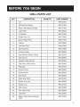 5
5
-
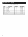 6
6
-
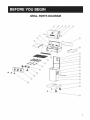 7
7
-
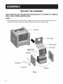 8
8
-
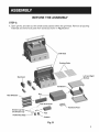 9
9
-
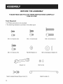 10
10
-
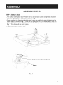 11
11
-
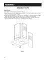 12
12
-
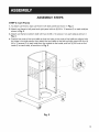 13
13
-
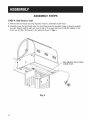 14
14
-
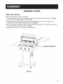 15
15
-
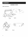 16
16
-
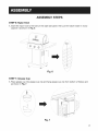 17
17
-
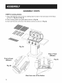 18
18
-
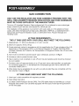 19
19
-
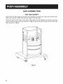 20
20
-
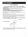 21
21
-
 22
22
-
 23
23
-
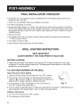 24
24
-
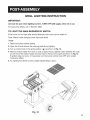 25
25
-
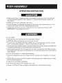 26
26
-
 27
27
-
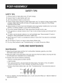 28
28
-
 29
29
-
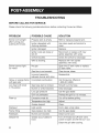 30
30
-
 31
31
-
 32
32
-
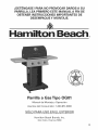 33
33
-
 34
34
-
 35
35
-
 36
36
-
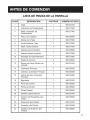 37
37
-
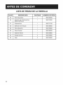 38
38
-
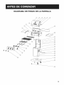 39
39
-
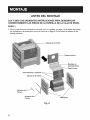 40
40
-
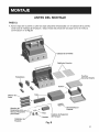 41
41
-
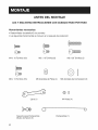 42
42
-
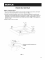 43
43
-
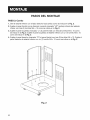 44
44
-
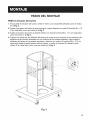 45
45
-
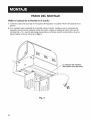 46
46
-
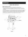 47
47
-
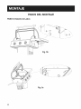 48
48
-
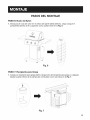 49
49
-
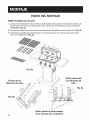 50
50
-
 51
51
-
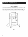 52
52
-
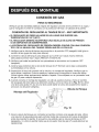 53
53
-
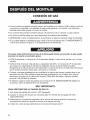 54
54
-
 55
55
-
 56
56
-
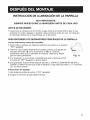 57
57
-
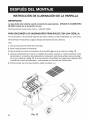 58
58
-
 59
59
-
 60
60
-
 61
61
-
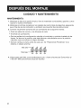 62
62
-
 63
63
-
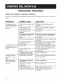 64
64
-
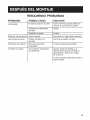 65
65
-
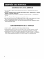 66
66
-
 67
67
-
 68
68


Proctor Silex 84131 El manual del propietario
- Categoría
- Barbacoas
- Tipo
- El manual del propietario
en otros idiomas
- English: Proctor Silex 84131 Owner's manual
Artículos relacionados
Otros documentos
-
Hamilton Beach OG01 Manual de usuario
-
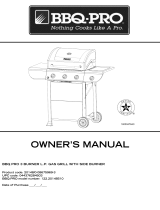 BBQ-Pro 720-0894 El manual del propietario
-
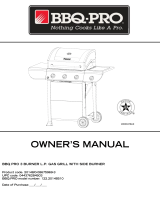 BBQ Pro 720-0894 El manual del propietario
-
Kenmore PG-40602SRL El manual del propietario
-
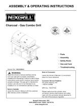 Nexgrill 720-718C El manual del propietario
-
-
 Nexgrill 720-0783D El manual del propietario
-
-
-
Electrolux EHED63CS Manual de usuario


