
Passion.Technology.Design.
12-24 Vdc
+
Art.20003400
A B D
-
Mod Bus
IT
MANUALE
TECNICO
EN
TECHNICAL
MANUAL
FR
MANUEL
TECHNIQUE
NL
TECHNISCHE
HANDLEIDING
ES
MANUAL
TÉCNICO
Interfaccia SimpleHome ModBus HVAC - Art. 20003400
HVAC ModBus SimpleHome interface - Art. 20003400
Interface SimpleHome Modbus - Art. 20003400
SimpleHome Modbus Interface - Art. 20003400
Interfaz SimpleHome Modbus HVAC - Art. 20003400

-
+
D
20004120
TEMPERATURE
SENSOR
NL
230V
~ ~
20022101 2A 24V
FAIL
-
+
NO
8
C8
8
NCNC
77
NO
C7C4
NO
4 4
NC NC
5
C5
5
NO
6
NC
C6
6
NO
NO
3
C3
NC
3
NO
2
C2
2
NCNC
11
NO
C1
IS
-
VV
+
K
I8I7I6I5I4I3I2I1
-
D
+
-
20046606 9I 8O 16A
HEATING CIRCUITS
TO VIP SYSTEM
D
+
-
L
N
D
+
-
L
N
-
VV
+
NO
4
C4
NC
4
NO
3
C3
NC
3
NO
2
C2
2
NCNC
11
NO
C1
KI4I3I2I1IS
-
D
+
-
20046604 5I 4O 16A
LOAD
LIGHT
M
ROLLING SHUTTER
COMMAND BUTTONS
20003400
-
+
D
-
BA
INTERFACE CDZ
BA
INTERFACE CDZ
BA
INTERFACE CDZ
BA
MODBUS
HEATING / COOLING MACHINE HEATING / COOLING MACHINE HEATING / COOLING MACHINE
ModBus Termination ON
-
+
-
+
-
+
CV1
POWER SUPPLY POWER SUPPLY
POWER SUPPLY
JP1
D
V
V
+
AL
PAN
CFP
J5
+
S
-
S
-
V
A
B
MA
MB
-
20003310W
20003310B
Icona Manager
• This Comelit product was designed for use in the creation of security and home automation systems in residential, commercial or industrial
settings and in public buildings or buildings used by the public.
• All activities connected to the installation of Comelit products must be carried out by qualified technical personnel, with careful observation
of the indications provided in the manuals / instruction sheets supplied with those products.
• Cut off the power supply before carrying out any maintenance procedures.
• Use wires with a cross-section suited to the distances involved, observing the instructions provided in the system manual.
• We advise against running the system wires through the same duct as the power cables (230V or higher).
• To ensure Comelit products are used safely: carefully observe the indications provided in the manuals / instruction sheets and make sure the
system created using Comelit products has not been tampered with / damaged.
• Comelit products do not require maintenance aside from routine cleaning, which should be carried out in accordance with the indications
provided in the manuals / instruction sheets. Any repair work must be carried out: for the products themselves, exclusively by Comelit Group
S.p.A., for systems, by qualified technical personnel.
• Comelit Group S.p.A. does not assume any responsibility for: any usage other than the intended use; non-observance of the indications
and warnings contained in this manual / instruction sheet. Comelit Group S.p.A. nonetheless reserves the right to change the information
provided in this manual / instruction sheet at any time and without prior notice.
32
IT
AVVERTENZE
WAARSCHUWINGEN
WARNING
AVERTISSEMENTS
ADVERTENCIAS
• Questo prodotto Comelit è progettato e realizzato con lo scopo di essere utilizzato nella realizzazione di sistemi per la sicurezza e la domotica
in edifici residenziali, commerciali, industriali e in edifici pubblici o ad uso pubblico.
• Tutte le attività connesse all’installazione dei prodotti Comelit devono essere realizzate da personale tecnicamente qualificato, seguendo
attentamente le indicazioni di manuali / istruzioni dei prodotti stessi.
• Togliere l’alimentazione prima di effettuare qualsiasi operazione.
• Utilizzare conduttori con sezione adeguata in funzione delle distanze, rispettando le indicazioni riportate nel manuale di sistema.
• Si consiglia di non posare i conduttori per l’impianto nella stessa tubazione dove transitano i cavi di potenza (230V o superiori).
• Per l’utilizzo sicuro dei prodotti Comelit è necessario: seguire con attenzione le indicazioni di manuali e istruzioni; curare che l’impianto
realizzato con i prodotti Comelit non sia manomesso / danneggiato.
• I prodotti Comelit non prevedono interventi di manutenzione ad eccezione delle normali operazioni di pulizia, da effettuarsi comunque
secondo quanto indicato in manuali / istruzioni. Eventuali riparazioni devono essere effettuate: per i prodotti, esclusivamente da Comelit
Group S.p.A., per gli impianti, da personale tecnicamente qualificato.
• Comelit Group S.p.A. non assume alcuna responsabilità per usi differenti da quello previsto e mancato rispetto di indicazioni ed avvertenze
presenti in questo manuale / istruzioni. Comelit Group S.p.A. si riserva comunque il diritto di modificare in qualsiasi momento e senza
preavviso quanto descritto nel presente manuale.
• Ce produit Comelit a été conçu et réalisé pour être utilisé dans la réalisation d'installations de systèmes de sécurité et domotiques dans des
bâtiments résidentiels, commerciaux, industriels et publics ou à usage public.
• Toutes les opérations liées à l'installation des produits Comelit sont réservées à des techniciens qualifiés qui devront suivre attentivement
les consignes des manuels desdits produits.
• Couper l'alimentation avant d'effectuer toute opération.
• Utiliser des conducteurs d'une section adéquate en fonction des distances et en respectant les explications contenues dans le manuel du système.
• Il est conseillé de ne pas poser les conducteurs destinés à l’installation dans la canalisation destinée aux câbles de puissance (230 V ou plus).
• Pour utiliser les produits Comelit en toute sécurité : suivre attentivement les consignes contenues dans les Manuels / Instructions; s'assurer
que l’installation réalisée avec les produits Comelit n'est pas sabotée / endommagée.
• Les produits Comelit sont sans maintenance, exception faite pour les opérations de nettoyage qui devront être effectuées selon les consignes
contenues dans les Manuels / Instructions. Les réparations concernant : les produits, sont réservées exclusivement à Comelit Group S.p.A.,
les installations, sont réservées à des techniciens qualifiés.
• Comelit Group S.p.A. ne sera pas tenue pour responsable en cas d'utilisation contraire aux indications, de non-respect des indications et
des recommandations présentes dans ce manuel. Comelit Group S.p.A. se réserve le droit de modifier à tout moment et sans préavis le
contenu de ce manuel.
• Dit product van Comelit is ontworpen en ontwikkeld om te worden gebruikt bij de realisatie van beveiligings- en huisautomatiseringssystemen
in woningen, winkels, bedrijven en openbare gebouwen of in openbare ruimtes.
• Alle functies die zijn aangesloten op de installatie van de Comelit-producten moeten zijn uitgevoerd door gekwalificeerd technisch personeel,
volgens de aanwijzingen in de handleiding/instructies van de betreffende producten.
• Sluit de voeding af voordat u onderhoudswerkzaamheden uitvoert.
• Gebruik kabels met een geschikte doorsnede, afhankelijk van de afstanden, volgens de aanwijzingen in de handleiding van de installatie.
• Het is raadzaam om de kabels voor de installatie niet in dezelfde leiding te plaatsen als die waar de vermogenskabels (230v of hoger) doorheen lopen.
• Voor een veilig gebruik van de producten Comelit is het volgende noodzakelijk: het zorgvuldig opvolgen van de aanwijzingen in de handleiding/
instructies, ervoor zorgen dat de installatie die met de Comelit-producten is uitgevoerd niet wordt gesaboteerd / beschadigd raakt.
• De producten van Comelit hebben geen onderhoud nodig, behalve de normale reiniging, welke moet worden uitgevoerd zoals is aangegeven
in de handleiding/instructies. Eventuele reparaties moeten worden uitgevoerd voor de producten, uitsluitend door Comelit Group S.p.A., voor
de installatie, door gekwalificeerd technisch personeel.
• Comelit Group S.p.A. is niet verantwoordelijkheid voor andere toepassingen dan het beoogde gebruik, het niet in acht nemen van de
aanwijzingen en waarschuwingen in deze handleiding/instructies. Comelit Group S.p.A. behoudt zich het recht voor om op elk moment,
zonder waarschuwing vooraf, wijzigingen aan te brengen in deze handleiding/instructies.
• Este producto Comelit ha sido diseñado y realizado para usarse en instalaciones de sistemas de seguridad y domótica tanto en edificios
residenciales, comerciales e industriales como en edificios públicos o de uso público.
• Todos los productos Comelit deben ser instalados por personal técnicamente cualificado, siguiendo con atención las indicaciones de los
manuales proporcionados con cada producto.
• Antes de efectuar cualquier operación hay que cortar la alimentación.
• Utilizar conductores de sección adecuada teniendo en cuenta las distancias y respetando las instrucciones del manual de sistema.
• Se aconseja no colocar los conductores de la instalación en el mismo conducto eléctrico por donde pasan los cables de potencia (230 V o superiores).
• Para el uso seguro de los productos Comelit, es necesario seguir con atención las indicaciones de los manuales / las instrucciones e
garantizar que la instalación realizada con los productos Comelit no pueda ser manipulada ni dañada.
• Los productos Comelit no prevén intervenciones de mantenimiento, salvo las normales operaciones de limpieza, que se deben efectuar
siempre según lo indicado en los manuales / las instrucciones. Las reparaciones deben ser efectuadas: exclusivamente por Comelit Group
S.p.A. cuando afecten a productos, por personal técnicamente cualificado cuando afecten a instalaciones.
• Comelit Group S.p.A. quedará libre de cualquier responsabilidad en caso de usos diferentes a los previstos e incumplimiento de las
indicaciones y advertencias proporcionadas en el manual. Comelit Group S.p.A. se reserva siempre el derecho de modificar en cualquier
momento y sin preaviso el manual.

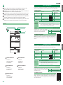
ART. 20003400
DESCRIZIONE DEL MODULO
1. Jumper CV1
2.
Morsetti di collegamento
3. Segnalazioni LED
BESCHRIJVING MODULE
1. Jumper CV1
2. Aansluitklemmen
3. Signaleringsled
MODULE DESCRIPTION
1. Jumper CV1
2. Connection terminal
3. Indicator LED
DESCRIPCIÓN DEL MÓDULO
1. Jumper CV1
2. Bornes de conexión
3. Led de señalización
DESCRIPTION MODULE
1. Jumper CV1
2. Bornes de connexion
3. LED de signalisation
INTERFACCIA SIMPLEHOME MODBUS
SIMPLEHOME MODBUS INTERFACE
PROGRAMMAZIONE E INDIRIZZAMENTO
PROGRAMMING AND ADDRESSING
JUMPER CV1
JUMPER CV1
Per la programmazione e l'indirizzamento dei dispositivi di automazione SimpleHome è necessario il software
SimpleProg scaricabile dal sito pro.comelitgroup.com. Per maggiori informazioni di programmazione e
per le funzionalità vedere il manuale SimpleProg sul sito pro.comelitgroup.com, o decodificare il seguente
codice QR:
SimpleHome automation devices must be programmed and addressed using the SimpleProg software,
available to download from the website pro.comelitgroup.com. For further information relating to
programming and functions, please refer to the SimpleProg manual on the website pro.comelitgroup.com
or decode the following QR code:
MORSETTI DI COLLEGAMENTO
A ModBus RS485 - A
B ModBus RS485 - B
D Linea BUS dati SimpleHome
+ Positivo di alimentazione
- Negativo di alimentazione
LAN /
CONNECTION TERMINALS
A ModBus RS485 - A
B ModBus RS485 - B
D BUS data line
+ Power supply positive
- Power supply negative
LAN /
CARATTERISTICHE TECNICHE
Tensione di alimentazione
12 / 24Vdc
Assorbimento 2,1W
Temperatura di funzionamento -5 - +45°C
Umidità di funzionamento 5 - 95%
Dimensioni 95 x 70 x 59 mm (4 moduli DIN)
Compatibilità Documento disponibile on-line
TECHNICAL CHARACTERISTICS
Power supply voltage
12 / 24Vdc
Consumption 2,1W
Operating temperature
-5 - +45°C
Operating humidity 5 - 95%
Dimensions 95 x 70 x 59 mm (4 DIN modules)
Compatibility Document available online
Chiuso Terminazione seriale ModBus abilitata
Aperto Terminazione seriale ModBus disabilitata
Closed ModBus serial termination enabled
Open ModBus serial termination disabled
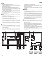
Il modulo 20003400 è un’interfaccia tra il sistema SimpleHome e il protocollo ModBus RTU/ASCII. Montato su barra DIN, il
dispositivo a 4 moduli è in grado di dialogare con sistemi di condizionamento attraverso interfacce ModBus dedicate.
Module 20003400 is an interface between the SimpleHome system and the Modbus RTU/ASCII protocol. Installed on a DIN rail, the
4-module device is capable of communicating with air conditioning systems via dedicated ModBus interfaces.
Sull’interfaccia 20003400 è presente un jumper per abilitare o
disabilitare la terminazione della linea seriale ModBus. La linea va
terminata sul primo e sull’ultimo dispositivo della linea.
The 20003400 interface includes a jumper for enabling or disabling
ModBus serial line termination. The line should be terminated at the
first and last device on the line.
SEGNALAZIONI
DL1 LED verde: stato tensione di alimentazione
DL4 • LED lampeggiante giallo: trasmissione di dati sul BUS SimpleHome
• LED fisso giallo: mancanza del negativo di alimentazione o collegamento errato del dispositivo
• LED rosso: possibile collisione di messaggi sul BUS SimpleHome
FLAGS
DL1 Green LED : power supply voltage status
DL4 • Flashing yellow LED: data transmission on BUS SimpleHome
• Steady yellow LED: power supply negative absent or incorrect connection of device
• Red LED: possible collision of messages on BUS SimpleHome
(Vedere schema di collegamento)
(See wiring diagram)
IT EN
12-24 Vdc
+
Art.20003400
A B D
-
Mod Bus
1.
3.
2.
È possibile utilizzare una sonda di temperatura del sistema SimpleHome per gestire più zone clima.
Non è possibile utilizzare sonde di temperatura di terze parti per effettuare la regolazione.
Er kan een temperatuursensor van het systeem SimpleHome worden gebruikt om meerdere klimaatzones te
beheren. Het is niet mogelijk om voor de regeling sensoren van andere merken te gebruiken.
A temperature sensor in the SimpleHome system can be used to manage several climate zones.
Third-party temperature sensors cannot be used for adjustment purposes.
Il est possible d’utiliser un capteur de température du système SimpleHome pour gérer plusieurs zones
climatisées. Il n'est pas possible d'utiliser des sondes de température de tiers pour procéder au réglage.
Es posible utilizar una sonda de temperatura del sistema SimpleHome para gestionar varias zonas de
climatización. No es posible utilizar sondas de temperatura de terceros para efectuar la regulación.
54

SIMPLEHOME-INTERFACE MODBUS
INTERFAZ SIMPLEHOME MODBUS
INTERFACE SIMPLEHOME MODBUS
PROGRAMMERING - ADRESSERING
PROGRAMACIÓN - DIRECCIONAMIENTO
PROGRAMMATION ET L'ADRESSAGE
JUMPER CV1
PUENTE CV1
CAVALIER CV1
Voor de programmering en adressering van de SimpleHome-automatiseringsapparaten kan de software
SimpleProg worden gedownload van de site pro.comelitgroup.com. Raadpleeg voor meer informatie
over de programmering en de functies de handleiding van SimpleProg via de website pro.comelitgroup.
com of scan de volgende QR-code:
Para programar y direccionar los dispositivos de automatización SimpleHome, se requiere el software
SimpleProg, que se puede descargar en el sitio pro.comelitgroup.com. Para más información sobre
la programación y las funciones, consultar el manual SimpleProg en el sitio pro.comelitgroup.com o
decodificando el siguiente código QR:
Pour la programmation et l'adressage des dispositifs d'automatisation SimpleHome, utiliser le logiciel
SimpleProg après l'avoir téléchargé sur le site pro.comelitgroup.com. Pour de plus amples informations
sur la programmation et le fonctionnement, consulter le manuel SimpleProg sur le site pro.comelitgroup.
com ou en lisant le code QR ci-après :
AANSLUITKLEMMEN
A ModBus RS485 - A
B ModBus RS485 - B
D Datalijn BUS
+ Plus van voeding
- Min van voeding
LAN /
BORNES DE CONEXIÓN
A ModBus RS485 - A
B ModBus RS485 - B
D Línea BUS datos
+ Positivo de alimentación
- Negativo de alimentación
LAN /
BORNES DE CONNEXION
A ModBus RS485 - A
B ModBus RS485 - B
D Ligne BUS données
+ Positif d'alimentation
- Négatif d'alimentation
LAN /
TECHNISCHE KENMERKEN
Voedingsspanning
12 / 24Vdc
Verbruik 2,1W
Bedrijfstemperatuur
-5 - +45°C
Vochtigheidsgraad voor bedrijf 5 - 95%
Afmetingen 95 x 70 x 59 mm (4 DIN-modulen)
Compatibiliteit Document online beschikbaar
CARACTERÍSTICAS TÉCNICAS
Tensión de alimentación
12 / 24Vdc
Consumo 2,1W
Temperatura de funcionamiento -5 - +45°C
Humedad de funcionamiento 5 - 95%
Dimensiones 95 x 70 x 59 mm (4 módulos DIN)
Compatibilidad Documento disponible en línea
CARACTÉRISTIQUES TECHNIQUES
Tension d'alimentation
12 / 24Vdc
Absorption 2,1W
Température de fonctionnement -5 - +45°C
Humidité de service 5 - 95%
Dimensions 95 x 70 x 59 mm (4 modules DIN)
Compatibilité Document disponible en ligne
Gesloten Seriële afsluiting ModBus ingeschakeld
Open Seriële afsluiting ModBus uitgeschakeld
Cerrado Terminación serial ModBus habilitada
Abierto
Terminación serial ModBus deshabilitada
Fermé Terminaison série ModBus activée
Ouvert Terminaison série ModBus désactivée
De module 20003400 is een interface tussen het systeem SimpleHome en het protocol ModBus RTU/ASCII. Het systeem met 4
modules is gemonteerd op een DIN-rail en kan communiceren met de airconditioningsystemen via de speciale ModBus-interface.
El módulo 20003400 es una interfaz entre el sistema SimpleHome y el protocolo ModBus RTU/ASCII. Montado en una barra DIN, el
dispositivo de 4 módulos puede dialogar con sistemas de aire acondicionado a través de interfaces específicas.
Le module 20003400 fait office d'interface entre le système SimpleHome et le protocole ModBus RTU/ASCII. Monté sur rail DIN,
le dispositif à 4 modules est en mesure de dialoguer avec systèmes de climatisation à travers des interfaces ModBus dédiées.
Op de interface 20003400 is een jumper aanwezig om de ModBus
seriële lijnafsluiting in of uit te schakelen. De lijn wordt afgesloten op
het eerste en het laatste apparaat van de lijn.
En la interfaz 20003400 hay un puente para habilitar o deshabilitar la
terminación de la línea serial ModBus. La línea se tiene que terminar
en el primer y el último dispositivo de la línea.
L'interface 20003400 présente un cavalier permettant d'activer ou de
désactiver la terminaison de la ligne série ModBus. La ligne termine
sur le premier et sur le dernier dispositif.
SIGNALERINGEN
DL1 Groene LED: Voedingsspanning
DL4 • Knipperende gele LED: gegevensoverdracht op BUS SimpleHome
• Vast brandende gele LED: min voeding ontbreekt of verkeerde aansluiting van de inrichting
• Rode LED: mogelijke interferentie van berichten op de BUS SimpleHome
SEÑALIZACIONE
DL1 LED verde: estado de tensión de alimentación
DL4 • LED parpadeante amarillo: transmisión de datos por el BUS SimpleHome
• LED fijo amarillo: falta el negativo de la alimentación o conexión del dispositivo errónea
• LED rojo: posible choque de mensajes por el BUS SimpleHome
SIGNALISATIONS
DL1 LED verte : état de tension d'alimentation
DL4 • LED jaune clignotante : transmission des données sur le BUS SimpleHome
• LED jaune allumée : absence du négatif d'alimentation ou connexion défectueuse du dispositif
• LED rouge : collision possible de messages sur le BUS SimpleHome
(zie aansluitschema)
(Véase el esquema de conexión)
(Voir schéma de connexion)
FR
NL
ES
76

2ª edizione 07/2019
cod. 2G40002401
www.comelitgroup.com
Via Don Arrigoni, 5 - 24020 Rovetta (BG) - Italy
CERTIFIED MANAGEMENT SYSTEMS
[Check for update]
Transcripción de documentos
IT EN FR NL ES MANUALE TECNICO TECHNICAL MANUAL MANUEL TECHNIQUE TECHNISCHE HANDLEIDING MANUAL TÉCNICO + - A B D Mod Bus 12-24 Vdc Art.20003400 Interfaccia SimpleHome ModBus HVAC - Art. 20003400 HVAC ModBus SimpleHome interface - Art. 20003400 Interface SimpleHome Modbus - Art. 20003400 SimpleHome Modbus Interface - Art. 20003400 Interfaz SimpleHome Modbus HVAC - Art. 20003400 Passion.Technology. Design. IT AVVERTENZE • Questo prodotto Comelit è progettato e realizzato con lo scopo di essere utilizzato nella realizzazione di sistemi per la sicurezza e la domotica in edifici residenziali, commerciali, industriali e in edifici pubblici o ad uso pubblico. • Tutte le attività connesse all’installazione dei prodotti Comelit devono essere realizzate da personale tecnicamente qualificato, seguendo attentamente le indicazioni di manuali / istruzioni dei prodotti stessi. • Togliere l’alimentazione prima di effettuare qualsiasi operazione. • Utilizzare conduttori con sezione adeguata in funzione delle distanze, rispettando le indicazioni riportate nel manuale di sistema. • Si consiglia di non posare i conduttori per l’impianto nella stessa tubazione dove transitano i cavi di potenza (230V o superiori). • Per l’utilizzo sicuro dei prodotti Comelit è necessario: seguire con attenzione le indicazioni di manuali e istruzioni; curare che l’impianto realizzato con i prodotti Comelit non sia manomesso / danneggiato. • I prodotti Comelit non prevedono interventi di manutenzione ad eccezione delle normali operazioni di pulizia, da effettuarsi comunque secondo quanto indicato in manuali / istruzioni. Eventuali riparazioni devono essere effettuate: per i prodotti, esclusivamente da Comelit Group S.p.A., per gli impianti, da personale tecnicamente qualificato. • Comelit Group S.p.A. non assume alcuna responsabilità per usi differenti da quello previsto e mancato rispetto di indicazioni ed avvertenze presenti in questo manuale / istruzioni. Comelit Group S.p.A. si riserva comunque il diritto di modificare in qualsiasi momento e senza preavviso quanto descritto nel presente manuale. WARNING • This Comelit product was designed for use in the creation of security and home automation systems in residential, commercial or industrial settings and in public buildings or buildings used by the public. • All activities connected to the installation of Comelit products must be carried out by qualified technical personnel, with careful observation of the indications provided in the manuals / instruction sheets supplied with those products. • Cut off the power supply before carrying out any maintenance procedures. • Use wires with a cross-section suited to the distances involved, observing the instructions provided in the system manual. • We advise against running the system wires through the same duct as the power cables (230V or higher). • To ensure Comelit products are used safely: carefully observe the indications provided in the manuals / instruction sheets and make sure the system created using Comelit products has not been tampered with / damaged. • Comelit products do not require maintenance aside from routine cleaning, which should be carried out in accordance with the indications provided in the manuals / instruction sheets. Any repair work must be carried out: for the products themselves, exclusively by Comelit Group S.p.A., for systems, by qualified technical personnel. • Comelit Group S.p.A. does not assume any responsibility for: any usage other than the intended use; non-observance of the indications and warnings contained in this manual / instruction sheet. Comelit Group S.p.A. nonetheless reserves the right to change the information provided in this manual / instruction sheet at any time and without prior notice. AVERTISSEMENTS • Ce produit Comelit a été conçu et réalisé pour être utilisé dans la réalisation d'installations de systèmes de sécurité et domotiques dans des bâtiments résidentiels, commerciaux, industriels et publics ou à usage public. • Toutes les opérations liées à l'installation des produits Comelit sont réservées à des techniciens qualifiés qui devront suivre attentivement les consignes des manuels desdits produits. • Couper l'alimentation avant d'effectuer toute opération. • Utiliser des conducteurs d'une section adéquate en fonction des distances et en respectant les explications contenues dans le manuel du système. • Il est conseillé de ne pas poser les conducteurs destinés à l’installation dans la canalisation destinée aux câbles de puissance (230 V ou plus). • Pour utiliser les produits Comelit en toute sécurité : suivre attentivement les consignes contenues dans les Manuels / Instructions; s'assurer que l’installation réalisée avec les produits Comelit n'est pas sabotée / endommagée. • Les produits Comelit sont sans maintenance, exception faite pour les opérations de nettoyage qui devront être effectuées selon les consignes contenues dans les Manuels / Instructions. Les réparations concernant : les produits, sont réservées exclusivement à Comelit Group S.p.A., les installations, sont réservées à des techniciens qualifiés. • Comelit Group S.p.A. ne sera pas tenue pour responsable en cas d'utilisation contraire aux indications, de non-respect des indications et des recommandations présentes dans ce manuel. Comelit Group S.p.A. se réserve le droit de modifier à tout moment et sans préavis le contenu de ce manuel. WAARSCHUWINGEN • Dit product van Comelit is ontworpen en ontwikkeld om te worden gebruikt bij de realisatie van beveiligings- en huisautomatiseringssystemen in woningen, winkels, bedrijven en openbare gebouwen of in openbare ruimtes. • Alle functies die zijn aangesloten op de installatie van de Comelit-producten moeten zijn uitgevoerd door gekwalificeerd technisch personeel, volgens de aanwijzingen in de handleiding/instructies van de betreffende producten. • Sluit de voeding af voordat u onderhoudswerkzaamheden uitvoert. • Gebruik kabels met een geschikte doorsnede, afhankelijk van de afstanden, volgens de aanwijzingen in de handleiding van de installatie. • Het is raadzaam om de kabels voor de installatie niet in dezelfde leiding te plaatsen als die waar de vermogenskabels (230v of hoger) doorheen lopen. • Voor een veilig gebruik van de producten Comelit is het volgende noodzakelijk: het zorgvuldig opvolgen van de aanwijzingen in de handleiding/ instructies, ervoor zorgen dat de installatie die met de Comelit-producten is uitgevoerd niet wordt gesaboteerd / beschadigd raakt. • De producten van Comelit hebben geen onderhoud nodig, behalve de normale reiniging, welke moet worden uitgevoerd zoals is aangegeven in de handleiding/instructies. Eventuele reparaties moeten worden uitgevoerd voor de producten, uitsluitend door Comelit Group S.p.A., voor de installatie, door gekwalificeerd technisch personeel. • Comelit Group S.p.A. is niet verantwoordelijkheid voor andere toepassingen dan het beoogde gebruik, het niet in acht nemen van de aanwijzingen en waarschuwingen in deze handleiding/instructies. Comelit Group S.p.A. behoudt zich het recht voor om op elk moment, zonder waarschuwing vooraf, wijzigingen aan te brengen in deze handleiding/instructies. ADVERTENCIAS • Este producto Comelit ha sido diseñado y realizado para usarse en instalaciones de sistemas de seguridad y domótica tanto en edificios residenciales, comerciales e industriales como en edificios públicos o de uso público. • Todos los productos Comelit deben ser instalados por personal técnicamente cualificado, siguiendo con atención las indicaciones de los manuales proporcionados con cada producto. • Antes de efectuar cualquier operación hay que cortar la alimentación. • Utilizar conductores de sección adecuada teniendo en cuenta las distancias y respetando las instrucciones del manual de sistema. • Se aconseja no colocar los conductores de la instalación en el mismo conducto eléctrico por donde pasan los cables de potencia (230 V o superiores). • Para el uso seguro de los productos Comelit, es necesario seguir con atención las indicaciones de los manuales / las instrucciones e garantizar que la instalación realizada con los productos Comelit no pueda ser manipulada ni dañada. • Los productos Comelit no prevén intervenciones de mantenimiento, salvo las normales operaciones de limpieza, que se deben efectuar siempre según lo indicado en los manuales / las instrucciones. Las reparaciones deben ser efectuadas: exclusivamente por Comelit Group S.p.A. cuando afecten a productos, por personal técnicamente cualificado cuando afecten a instalaciones. • Comelit Group S.p.A. quedará libre de cualquier responsabilidad en caso de usos diferentes a los previstos e incumplimiento de las indicaciones y advertencias proporcionadas en el manual. Comelit Group S.p.A. se reserva siempre el derecho de modificar en cualquier momento y sin preaviso el manual. D D + + - - Icona Manager 20003310W 20003310B MB + - D + - IS I1 I2 I3 I4 I5 I6 I7 I8 V V K D + + - - IS I1 I2 I3 I4 V V K + - D + V B FAIL - 20046606 9I 8O 16A ~230V~ B D + - - JP1 S NO C1 NC NO C2 NC NO C3 NC NO C4 NC 1 1 2 2 3 3 4 4 + NO C7 NC NO C8 NC 7 7 8 8 AL J5 NO C4 NC NO C5 NC NO C6 NC 4 4 5 5 6 6 A 20003400 SNO C1 NC NO C2 NC NO C3 NC 1 1 2 2 3 3 CV1 V- - 20046604 5I 4O 16A 20004120 N - V+ A 20022101 2A 24V L D MA - MODBUS TEMPERATURE SENSOR PAN CFP TO VIP SYSTEM L L N N ModBus Termination ON A M B + - INTERFACE CDZ LIGHT LOAD ROLLING SHUTTER + - A B + - INTERFACE CDZ POWER SUPPLY POWER SUPPLY COMMAND BUTTONS HEATING / COOLING MACHINE 2 B INTERFACE CDZ POWER SUPPLY HEATING CIRCUITS A HEATING / COOLING MACHINE HEATING / COOLING MACHINE 3 INTERFACCIA SIMPLEHOME MODBUS CARATTERISTICHE TECNICHE MORSETTI DI COLLEGAMENTO Tensione di alimentazione 12 / 24Vdc A ModBus RS485 - A Assorbimento 2,1W B ModBus RS485 - B Temperatura di funzionamento -5 - +45°C D Linea BUS dati SimpleHome Er kan een temperatuursensor van het systeem SimpleHome worden gebruikt om meerdere klimaatzones te beheren. Het is niet mogelijk om voor de regeling sensoren van andere merken te gebruiken. Umidità di funzionamento 5 - 95% + Positivo di alimentazione Dimensioni 95 x 70 x 59 mm (4 moduli DIN) - Negativo di alimentazione Es posible utilizar una sonda de temperatura del sistema SimpleHome para gestionar varias zonas de climatización. No es posible utilizar sondas de temperatura de terceros para efectuar la regulación. Compatibilità Documento disponibile on-line LAN DL1 SEGNALAZIONI ART. 20003400 1. 2. 3. DL4 IT È possibile utilizzare una sonda di temperatura del sistema SimpleHome per gestire più zone clima. Non è possibile utilizzare sonde di temperatura di terze parti per effettuare la regolazione. A temperature sensor in the SimpleHome system can be used to manage several climate zones. Third-party temperature sensors cannot be used for adjustment purposes. Il est possible d’utiliser un capteur de température du système SimpleHome pour gérer plusieurs zones climatisées. Il n'est pas possible d'utiliser des sondes de température de tiers pour procéder au réglage. Il modulo 20003400 è un’interfaccia tra il sistema SimpleHome e il protocollo ModBus RTU/ASCII. Montato su barra DIN, il dispositivo a 4 moduli è in grado di dialogare con sistemi di condizionamento attraverso interfacce ModBus dedicate. / LED verde: stato tensione di alimentazione • LED lampeggiante giallo: trasmissione di dati sul BUS SimpleHome • LED fisso giallo: mancanza del negativo di alimentazione o collegamento errato del dispositivo • LED rosso: possibile collisione di messaggi sul BUS SimpleHome JUMPER CV1 (Vedere schema di collegamento) Sull’interfaccia 20003400 è presente un jumper per abilitare o disabilitare la terminazione della linea seriale ModBus. La linea va terminata sul primo e sull’ultimo dispositivo della linea. Chiuso Terminazione seriale ModBus abilitata Aperto Terminazione seriale ModBus disabilitata PROGRAMMAZIONE E INDIRIZZAMENTO A B D + Mod Bus - 12-24 Vdc Art.20003400 Per la programmazione e l'indirizzamento dei dispositivi di automazione SimpleHome è necessario il software SimpleProg scaricabile dal sito pro.comelitgroup.com. Per maggiori informazioni di programmazione e per le funzionalità vedere il manuale SimpleProg sul sito pro.comelitgroup.com, o decodificare il seguente codice QR: SIMPLEHOME MODBUS INTERFACE TECHNICAL CHARACTERISTICS DESCRIZIONE DEL MODULO BESCHRIJVING MODULE 1. Jumper CV1 2. Morsetti di collegamento 3. Segnalazioni LED 1. Jumper CV1 2. Aansluitklemmen 3. Signaleringsled MODULE DESCRIPTION DESCRIPCIÓN DEL MÓDULO 1. Jumper CV1 2. Connection terminal 3. Indicator LED 1. Jumper CV1 2. Bornes de conexión 3. Led de señalización DESCRIPTION MODULE 1. Jumper CV1 2. Bornes de connexion 3. LED de signalisation 4 CONNECTION TERMINALS Power supply voltage 12 / 24Vdc A ModBus RS485 - A Consumption 2,1W B ModBus RS485 - B Operating temperature -5 - +45°C D BUS data line Operating humidity 5 - 95% + Power supply positive Dimensions 95 x 70 x 59 mm (4 DIN modules) - Power supply negative Compatibility Document available online DL1 FLAGS DL4 LAN / Green LED : power supply voltage status • Flashing yellow LED: data transmission on BUS SimpleHome • Steady yellow LED: power supply negative absent or incorrect connection of device • Red LED: possible collision of messages on BUS SimpleHome JUMPER CV1 The 20003400 interface includes a jumper for enabling or disabling ModBus serial line termination. The line should be terminated at the first and last device on the line. (See wiring diagram) Closed ModBus serial termination enabled Open ModBus serial termination disabled PROGRAMMING AND ADDRESSING SimpleHome automation devices must be programmed and addressed using the SimpleProg software, available to download from the website pro.comelitgroup.com. For further information relating to programming and functions, please refer to the SimpleProg manual on the website pro.comelitgroup.com or decode the following QR code: 5 EN Module 20003400 is an interface between the SimpleHome system and the Modbus RTU/ASCII protocol. Installed on a DIN rail, the 4-module device is capable of communicating with air conditioning systems via dedicated ModBus interfaces. FR INTERFAZ SIMPLEHOME MODBUS El módulo 20003400 es una interfaz entre el sistema SimpleHome y el protocolo ModBus RTU/ASCII. Montado en una barra DIN, el dispositivo de 4 módulos puede dialogar con sistemas de aire acondicionado a través de interfaces específicas. CARACTÉRISTIQUES TECHNIQUES BORNES DE CONNEXION Tension d'alimentation 12 / 24Vdc A ModBus RS485 - A Absorption 2,1W B ModBus RS485 - B Température de fonctionnement -5 - +45°C D Ligne BUS données Humidité de service 5 - 95% + Positif d'alimentation Dimensions 95 x 70 x 59 mm (4 modules DIN) - Négatif d'alimentation Compatibilité Document disponible en ligne DL1 SIGNALISATIONS DL4 LAN / CARACTERÍSTICAS TÉCNICAS 12 / 24Vdc A ModBus RS485 - A Consumo 2,1W B ModBus RS485 - B Temperatura de funcionamiento -5 - +45°C D Línea BUS datos Humedad de funcionamiento 5 - 95% + Positivo de alimentación Dimensiones 95 x 70 x 59 mm (4 módulos DIN) - Negativo de alimentación Compatibilidad Documento disponible en línea LED verte : état de tension d'alimentation DL1 • LED jaune clignotante : transmission des données sur le BUS SimpleHome • LED jaune allumée : absence du négatif d'alimentation ou connexion défectueuse du dispositif • LED rouge : collision possible de messages sur le BUS SimpleHome CAVALIER CV1 (Voir schéma de connexion) L'interface 20003400 présente un cavalier permettant d'activer ou de désactiver la terminaison de la ligne série ModBus. La ligne termine sur le premier et sur le dernier dispositif. Fermé Terminaison série ModBus activée Ouvert Terminaison série ModBus désactivée PROGRAMMATION ET L'ADRESSAGE BORNES DE CONEXIÓN Tensión de alimentación SEÑALIZACIONE DL4 LAN / LED verde: estado de tensión de alimentación • LED parpadeante amarillo: transmisión de datos por el BUS SimpleHome • LED fijo amarillo: falta el negativo de la alimentación o conexión del dispositivo errónea • LED rojo: posible choque de mensajes por el BUS SimpleHome PUENTE CV1 En la interfaz 20003400 hay un puente para habilitar o deshabilitar la terminación de la línea serial ModBus. La línea se tiene que terminar en el primer y el último dispositivo de la línea. (Véase el esquema de conexión) Cerrado Terminación serial ModBus habilitada Abierto Terminación serial ModBus deshabilitada PROGRAMACIÓN - DIRECCIONAMIENTO Pour la programmation et l'adressage des dispositifs d'automatisation SimpleHome, utiliser le logiciel SimpleProg après l'avoir téléchargé sur le site pro.comelitgroup.com. Pour de plus amples informations sur la programmation et le fonctionnement, consulter le manuel SimpleProg sur le site pro.comelitgroup. com ou en lisant le code QR ci-après : Para programar y direccionar los dispositivos de automatización SimpleHome, se requiere el software SimpleProg, que se puede descargar en el sitio pro.comelitgroup.com. Para más información sobre la programación y las funciones, consultar el manual SimpleProg en el sitio pro.comelitgroup.com o decodificando el siguiente código QR: NL SIMPLEHOME-INTERFACE MODBUS De module 20003400 is een interface tussen het systeem SimpleHome en het protocol ModBus RTU/ASCII. Het systeem met 4 modules is gemonteerd op een DIN-rail en kan communiceren met de airconditioningsystemen via de speciale ModBus-interface. TECHNISCHE KENMERKEN AANSLUITKLEMMEN Voedingsspanning 12 / 24Vdc A ModBus RS485 - A Verbruik 2,1W B ModBus RS485 - B Bedrijfstemperatuur -5 - +45°C D Datalijn BUS Vochtigheidsgraad voor bedrijf 5 - 95% + Plus van voeding Afmetingen 95 x 70 x 59 mm (4 DIN-modulen) - Min van voeding Compatibiliteit Document online beschikbaar DL1 SIGNALERINGEN DL4 LAN / Groene LED: Voedingsspanning • Knipperende gele LED: gegevensoverdracht op BUS SimpleHome • Vast brandende gele LED: min voeding ontbreekt of verkeerde aansluiting van de inrichting • Rode LED: mogelijke interferentie van berichten op de BUS SimpleHome JUMPER CV1 Op de interface 20003400 is een jumper aanwezig om de ModBus seriële lijnafsluiting in of uit te schakelen. De lijn wordt afgesloten op het eerste en het laatste apparaat van de lijn. (zie aansluitschema) Gesloten Seriële afsluiting ModBus ingeschakeld Open Seriële afsluiting ModBus uitgeschakeld PROGRAMMERING - ADRESSERING Voor de programmering en adressering van de SimpleHome-automatiseringsapparaten kan de software SimpleProg worden gedownload van de site pro.comelitgroup.com. Raadpleeg voor meer informatie over de programmering en de functies de handleiding van SimpleProg via de website pro.comelitgroup. com of scan de volgende QR-code: 6 7 ES INTERFACE SIMPLEHOME MODBUS Le module 20003400 fait office d'interface entre le système SimpleHome et le protocole ModBus RTU/ASCII. Monté sur rail DIN, le dispositif à 4 modules est en mesure de dialoguer avec systèmes de climatisation à travers des interfaces ModBus dédiées. 2ª edizione 07/2019 cod. 2G40002401 [Check for update] CERTIFIED MANAGEMENT SYSTEMS w w w.comelitgroup.com Via Don Arrigoni, 5 - 24020 Rovetta (BG) - Italy-
 1
1
-
 2
2
-
 3
3
-
 4
4
-
 5
5


en otros idiomas
- français: Comelit 20003400
- italiano: Comelit 20003400
- English: Comelit 20003400
- Nederlands: Comelit 20003400
Artículos relacionados
-
Comelit ONE Technical Manual
-
-
Comelit 6702W El manual del propietario
-
-
Comelit 20004606 Manual de usuario
-
-
-
Comelit 6214C Technical Sheet
-
-