
ACCESSORY ITEMS
•Power cable
Taiwan, Mexico, Middle Latin America models x 2
All other models x 1
•RCA plug cord x 1
• Operating instructions
FEATURES
• Deep bass sound
• Phase Control engineering
• Simply and clean design
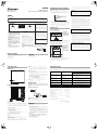
IN COMBINATION WITH SPEAKERS
The frequency characteristics of the S-51W combined with small-size
speakers are shown below. As shown in these figures, the low
frequency range is improved.
• These special characteristics are obtained in an echoless chamber.
The effect of an additional S-51W in an ordinary listening room is
better than the chart indicates when positioned adequately.
• With playback of Dolby* Digital, establishment of a special channel
for the subwoofer is recommended; and with playback of LFE (Low
Frequency Effect: sound effect like the rumbling of the earth, whose
purpose is to intensify the force of the video), the S-51W is especially
effective.
* Manufactured under license from Dolby Laboratories. “Dolby” and
the double-D symbol are trademarks of Dolby Laboratories.
INSTALLATION
Speaker Installation
• Subwoofer Installation Criteria
1 Left speaker
2 Right speaker
3 Recommended
installation range
for the subwoofer
4 Listening position
The subwoofer plays back the bass in monaural, making use of the fact
that the human ear is not very sensitive to the direction of low-pitched
sound. Because of this, the subwoofer can be installed almost
anywhere. If it is installed too far away, however, the sound from the
other speakers may become unnatural.
• An example of speaker positioning
1 Front left speaker
2 Center speaker
3 Front right speaker
4Subwoofer
5 Listening area
6 Rear left speaker
7 Rear right speaker
NOTES:
• Position the left and right channel speakers at equal distances from
the TV set and approximately 1.8 meters from each other.
• Install the center speaker above or below the TV so that the sound of
the center channel is localized at the TV screen.
• The rear (surround) speakers are most effective when installed in
parallel locations directly to the side, or slightly behind, the listener,
at a level about 1 meter above the listener’s ears.
Installation Precautions
• Do not attach the subwoofer to the wall or ceiling. They may fall off
and cause injury.
• Install the unit in a well-ventilated location where it will not be
exposed to high temperatures and high humidity.
• Do not place the unit near stoves or other heating equipment or at
locations exposed to direct sunlight, as these can have an adverse
effect on the cabinet and internal components. Also, do not install
the unit where there is too much dust or high humidity, as these can
cause malfunctioning or breakdowns. (Avoid cooking tables and
other locations where the unit would be exposed to heat, steam and
soot.)
• Do not place heavy or large objects on top of the speaker. Doing so
could provoke the speaker to fall, causing damages or bodily injury.
If speakers fall from their installation locations, they may suffer
irreparable cracks in their finish.
• Keep the unit away from devices such as cassette decks which are
sensitive to magnetic fields.
• Do not place the speaker on an unstable surface, as doing so may
cause the speaker to fall and cause damage or bodily injury.
• Do not place cups, glasses, or other containers with fluids on top of
the units, since the units may be damaged if the liquid spills.
• The installation location selected should have a sturdy floor surface.
Mounting the speaker on a long-pile carpet should be avoided, since
the carpet may touch the driver’s diaphram, causing distorted
sound.
• Please install this unit away from the antenna cable of the tuner, as
noise can be caused with installation close to the antenna cable. In
such a case, use this unit at a position away from the antenna and
the antenna cable, or when playback of extra bass is not required,
switch off the power for this unit.
Small-size speakers + S-51W
Small-size speaker
FREQUENCY (Hz)
RESPONCE (dB)
3
12
4
1
4
2
3
67
5
CAUTION:
When installing the center speaker on top of the TV, be sure to
secure it with tape or some other suitable means.
Otherwise, the speaker may fall from the TV due to external shocks
such as earthquakes, and it may lead to endangering those nearby
or damaging the speaker.
The subwoofer is not magnetically shielded and so should not be
placed near a CRT-based TV or color monitor. Magnetic storage
media (such as floppy discs and tape or video cassettes) should
also not be kept close to the subwoofer.
MAINTENANCE OF EXTERNAL SURFACES:
• Clean the surface by wiping with a soft, dry cloth.
• When the surfaces are very dirty, wipe with a soft cloth dipped in
some neutral cleanser diluted five or six times with water, and
wrung out well, and then wipe again with a dry cloth. Do not use
furniture wax or cleaners.
• Never use thinners, benzine, insecticide sprays and other
chemicals on or near this unit, since these will corrode the
surfaces.
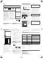
PANEL FACILITIES
FRONT PANEL
REAR PANEL
1 Power Indicator (STANDBY/ON)
Lights blue when the power has been switched ON.
NOTE:
• The power is still supplied even when the power indicator is off. The
power plug (interrupter) must be unplugged in order to completely
cut the power supply. When not using this product for long periods
of time, such as when traveling, unplug the power cord (interrupter)
from the power outlet for safety purposes. Failure to do so could lead
to fire.
2 Power switch (POWER)
Switches the subwoofer between ON and OFF.
3 Volume knob (VOLUME)
Sets the subwoofer volume.
• Turn the knob slowly from the MIN position.
• With this unit, the bass level can be independently set, so do not
turn up the bass on the AV amplifier.
4 Auto Standby switch (AUTO STANDBY)
Turning the Auto Standby function on or off.
NOTE:
• The default setting for Auto Standby switch is ON.
Auto standby function
The power is automatically set to the standby mode (off) if there is no
input signal for approximately 12 minutes (the power indicator turns
red). The power automatically turns on when a signal is input. The auto
standby function is deactivated when Auto Standby switch is set to OFF.
NOTE:
• There may be cases where a connected component outputs noise or
some other non-audio signal which causes this system to
automatically power on when in Auto Standby mode. If this happens,
switch off the Auto Standby mode and switch the system on/off
manually.
5 Phase switch (PHASE)
When set to 180
°, the output phase becomes the reverse of the input
signal, and when set to 0
°, it is in the same phase as the input signal.
• Normally, the switch is set to 0
°.
But when the sound connection between the subwoofer and the
left and right speakers sounds unnatural, try switching to 180
° and
set the switch in the position where the sound is natural.
6 Line Level Input terminal (LINE IN)
Connect to the SUBWOOFER PREOUT terminal of an amplifier or
receiver, with the specially provided RCA plug cord.
7AC IN
• Connect the power cord to the powered subwoofer unit’s AC IN.
• Connect the power cord to a AC socket.
CONNECTIONS
Before making or changing any connections, switch off the power
and disconnect both this unit and the amplifier/receiver from the
AC outlet.
LINE LEVEL CONNECTION
Connect the set's LINE IN terminal to the amplifier or receiver's
SUBWOOFER PREOUT terminal using the included RCA pin cord.
NOTE:
• When connected to the PREOUT terminal for surround center
channel on the amplifier or receiver, the bass is heard only on the
center channel, so it will be insufficient.
OPERATION
For details regarding operating part functions, refer to PANEL
FACILITIES above.
1. Turn the POWER switch (2) ON.
• If the unit’s power cord is connected to a switched AC outlet on
the amplifier or receiver and the switch is left ON, the unit can be
turned ON/OFF together with the amplifier or receiver.
• If the unit cannot be connected to the amplifier or receiver, turn
the power to the amplifier or receiver ON before turning the power
to the unit ON. When turning the power OFF, turn the power to the
unit OFF before turning the power to the amplifier or receiver OFF.
2. Operate the amplifier or receiver and adjust the volume of the
other speakers.
3. Adjust the volume of the bass with the VOLUME knob (3).
• When necessary, operate the PHASE switch (5) and then adjust
with the VOLUME knob (3).
4. Turn the POWER switch (2) OFF.
•The power indicator disappears.
1
STANDBY/ON
3
5
7
4
6
2
Rear Panel
Supplied RCA plug cord
TROUBLESHOOTING
Incorrect operations are often mistaken for trouble and malfunctions. If you think that there is something wrong with this component, check the
points below. Sometimes the trouble may lie in another component. Investigate the other components and electrical appliances being used. If the
trouble cannot be rectified even after exercising the checks listed below, ask your nearest PIONEER authorized service center or your dealer to carry
out repair work.
SPECIFICATIONS
Cabinet ............................................................Bass-reflex, floor-standing type
Speaker..................................................................................... 20 cm cone type
Power Amplifier Continuous Power Output (RMS)
Taiwan, Mexico, Middle Latin America models .............130 W/6 Ω (100 Hz)
All other models................................................................150 W/6 Ω (100 Hz)
Input (sensitivity at 100 Hz)
LINE LEVEL (RCA jack) .........................................................................190 mV
Outline Dimension ..........................360 mm (W) x 382 mm (H) x 360 mm (D)
Weight (without package)....................................................................... 13.5 kg
Power Requirements
Taiwan, Mexico, Middle Latin America models .......110 V to 127 V~, 60 Hz
All other models............................................... 220 V to 240 V~, 50 Hz/60 Hz
Power Consumption..................................................................................130 W
Power consumption in standby.................................................. 0.45 W or less
Specifications and design subject to possible modification without
notice, due to improvements.
Published by Pioneer Corporation.
Copyright © 2009 Pioneer Corporation.
All rights reserved.
SYMPTOM CAUSE REMEDY
1 No power is being supplied
(Indicator does not light up when
power switch is turned on.)
• Power supply plug is not correctly
inserted.
• Insert plug securely.
2No sound
(Indicator is lit.)
• Connection of accessory RCA plug
cord is wrong or disconnected.
• VOLUME knob is set to MIN.
• Check again and connect correctly.
• Turn clockwise slowly.
3 Sound is distorted. • Level is too high.
• Input level is too high.
• Turn the VOLUME knob counter-clockwise to lower the level.
• Turn the amplifier’s output level (volume, bass control, bass
boost) counter-clockwise to lower the level.
4 Howling noise occurs. • No power supplied to the amplifier.
• Subwoofer level is set too high.
• Connect an amplifier and supply power.
• Place the subwoofer a good distance from speakers. Turn the
VOLUME knob counter-clockwise to lower the volume.
5 Much noise when listening to
AM or FM broadcasts.
• The AM loop antenna or the FM indoor
antenna is close to this unit.
• Increase the distance between the AM or FM antenna (for
indoor use) and this unit.
6 Sound is broken. • Auto standby function is on. • Turn the auto standby function off.
7 Power indicator is lit red. • Auto Standby function is on. • Turn the auto standby function off.
Operating Instructions
Manual de instrucciones
S-51W
POWERED SUBWOOFER
ALTAVOCES DE GRAVES SECUNDARIOS ENERGIZADOS
WARNING
This equipment is not waterproof. To prevent a fire
or shock hazard, do not place any container filled
with liquid near this equipment (such as a vase or
flower pot) or expose it to dripping, splashing, rain
or moisture.
D3-4-2-1-3_B_En
WARNING
The voltage of the available power supply differs
according to country or region. Be sure that the
power supply voltage of the area where this unit
will be used meets the required voltage (e.g., 230 V
or 120 V) written on the rear panel.
D3-4-2-1-4_A_En
Before plugging in for the first time, read the following
section carefully.
WARNING
To prevent a fire hazard, do not place any naked
flame sources (such as a lighted candle) on the
equipment.
D3-4-2-1-7a_A_En
VENTILATION CAUTION
When installing this unit, make sure to leave space
around the unit for ventilation to improve heat
radiation (at least 15 cm at top, 15 cm at rear, and
15 cm at each side).
WARNING
Slots and openings in the cabinet are provided for
ventilation to ensure reliable operation of the
product, and to protect it from overheating. To
prevent fire hazard, the openings should never be
blocked or covered with items (such as newspapers,
table-cloths, curtains) or by operating the
equipment on thick carpet or a bed.
D3-4-2-1-7b_A_En
CAUTION
The POWER switch on this unit will not completely
shut off all power from the AC outlet. Since the
power cord ser ves as the main disconnect device for
the unit, you will need to unplug it from the AC outlet
to shut down all power. Therefore, make sure the
unit has been installed so that the power cord can
be easily unplugged from the AC outlet in case of an
accident. To avoid fire hazard, the power cord should
also be unplugged from the AC outlet when left
unused for a long period of time (for example, when
on vacation).
D3-4-2-2-2a_A_En
POWER-CORD CAUTION
Handle the power cord by the plug. Do not pull out the
plug by tugging the cord and never touch the power
cord when your hands are wet as this could cause a
short circuit or electric shock. Do not place the unit, a
piece of furniture, etc., on the power cord, or pinch the
cord. Never make a knot in the cord or tie it with other
cords. The power cords should be routed such that they
are not likely to be stepped on. A damaged power cord
can cause a fire or give you an electrical shock. Check
the power cord once in a while. When you find it
damaged, ask your nearest PIONEER authorized
ser vice center or your dealer for a replacement.
S002*_En
Thank you for buying this PIONEER product. Please read through these operating instructions so you will know how to operate your model properly. After you
have finished reading the instructions, put them away in a safe place for future reference.
In some countries or regions, the shape of the power plug and power outlet may sometimes differ from that shown in the explanatory drawings. However, the
method of connecting and operating the unit is the same.
For Taiwan and Mexico exclusively
Taiwanese two pin flat-bladed plug
WARNING:
Do not climb or sit on this unit. Be especially
careful when children are around. The unit may be
damaged, or may fall over causing injury.
This product is for general household purposes. Any
failure due to use for other than household purposes
(such as long-term use for business purposes in a
restaurant or use in a car or ship) and which
requires repair will be charged for even during the
warranty period.
K041_En
The exclamation point within an equilateral
triangle is intended to alert the user to the
presence of important operating and
maintenance (servicing) instructions in the
literature accompanying the appliance.
The lightning flash with arrowhead symbol,
within an equilateral triangle, is intended to
alert the user to the presence of uninsulated
“dangerous voltage” within the product’s
enclosure that may be of sufficient
magnitude to constitute a risk of electric
shock to persons.
CAUTION:
TO PREVENT THE RISK OF ELECTRIC
SHOCK, DO NOT REMOVE COVER (OR
BACK). NO USER-SERVICEABLE PARTS
INSIDE. REFER SERVICING TO QUALIFIED
SERVICE PERSONNEL.
CAUTION
RISK OF ELECTRIC SHOCK
DO NOT OPEN
IMPORTANT
D3-4-2-1-1_A1_En
If the AC plug of this unit does not match the AC
outlet you want to use, the plug must be removed
and appropriate one fitted. Replacement and
mounting of an AC plug on the power supply cord of
this unit should be performed only by qualified
service personnel. If connected to an AC outlet, the
cut-off plug can cause severe electrical shock. Make
sure it is properly disposed of after removal.
The equipment should be disconnected by removing
the mains plug from the wall socket when left unused
for a long period of time (for example, when on
vacation).
D3-4-2-2-1a_A1_En
Operating Environment
Operating environment temperature and humidity:
+5 °C to +35 °C (+41 °F to +95 °F); less than 85 %RH
(cooling vents not blocked)
Do not install this unit in a poorly ventilated area, or in
locations exposed to high humidity or direct sunlight (or
strong artificial light)
D3-4-2-1-7c*_A1_En
English
S-51W_XRC3475A.book 1 ページ 2009年6月4日 木曜日 午後3時5分

ACCESORIOS INCLUIDOS
•Cable de alimentación
Taiwán, México, Latinoamérica central x 2
Todos los otros modelos x 1
• Cable de clavija RCA x 1
• Manual de instrucciones
CARACTERÍSTICAS
• Sonido con graves intensos
• Ingeniería de control de fase
• Diseño sencillo y organizado
EN COMBINACIÓN CON ALTAVOCES
A continuación se muestran las características de frecuencia del
S-51W combinado con altavoces de tamaño pequeño. Como se
muestra en estas figuras, la gama de frecuencias bajas es mejorada.
• Estas características especiales se obtienen en una cámara sin eco.
El efecto de un S-51W en una sala de audición normal es major que
la que indica la gráfica cuando se ubica adecuadamente.
•
Con la reproducción de Dolby* Digital, se recomienda el establecimiento
de un canal especial para el altavoz de subgraves, y con la
reproducción de LFE (efecto de bajas frecuencias: efecto de sonido
similar al retumbar de la tierra, cuyo propósito es el de intensificar la
fuerza del vídeo), el S-51W es especialmente efectivo.
* Fabricado bajo licencia de Dolby Laboratories. “Dolby” y el símbolo de
la doble D son marcas comerciales de Dolby Laboratories.
INSTALACIÓN
Insalación de altavoz
• Criterio de instalación del altavoz de subgraves
1 Altavoz izquierdo
2Altavoz derecho
3
Espacio recomendado
para la instalación
del altavoz de
subgraves
4 Posición de audición
El altavoz de subgraves reproduce los graves con sonido monofónico,
empleando el hecho de que el oído humano no es muy sensible a la
dirección de los sonidos de tono bajo. Por este motivo, el altavoz de
subgraves puede instalarse casi en cualquier lugar. Sin embargo, si se
instala demasiado alejado, el sonido de los otros altavoces puede
perder naturalidad.
• Un ejemplo de ubicación de los altavoces
1 Altavoz izquierdo
delantero
2 Altavoz central
3 Altavoz derecho
delantero
4 Altavoz de subgraves
5 Area de audición
6 Altavoz izquierdo
trasero
7 Altavoz derecho
trasero
NOTAS:
• Ubique los altavoces de los canales izquierdo y derecho
equidistantes del televisor, y aproximadamente a 1,8 metros entre sí.
• Instale el altavoz central encima o debajo del televisor, de forma que
el sonido del canal central quede ubicado a la altura de la pantalla.
• Los altavoces traseros (envolvente) son más efectivos cuando se
instalan en ubicaciones paralelas directamente al lado, o
ligeramente detrás del oyente, en un nivel de aproximadamente
1 metro por encima de los oídos del oyente.
Precauciones de instalación
• No instale el subwoofer en la pared o en el techo. Podría caerse y
causar daños.
• Instale la unidad en un lugar bien ventilado en donde no quede
expuesta a altas temperaturas ni alta humedad.
• No coloque la unidad cerca de estufas u otros equipos de
calefacción ni en lugares expuestos a la luz directa del sol, ya que
puede tener un efecto adverso sobre la caja y los componentes
internos. No instale tampoco la unidad en donde haya mucho polvo
o alta humedad, ya que pueden ocasionarse fallas de
funcionamiento o averías. (Evite las cocinas y otros lugares en donde
la unidad quede expuesta al calor, vapor y humedad.)
• No ponga objetos pesados ni grandes sobre el altavoz. De lo
contrario podría ocasionar la caída del altavoz y sufrir daños
materiales o heridas personales. Si los altavoces se caen de las
posiciones en las que están instalados, pueden sufrir roturas
irreparables en su acabado.
• Mantenga la unidad alejada de dispositivos tales como platinas de
cassettes que son sensibles a los campos magnéticos.
• No ponga el altavoz sobre una superficie inestable, porque, de lo
contrario, el altavoz podría caerse y causar daños materiales o
heridas personales.
• No ponga tazas, vasos, ni otros tipos de recipientes con líquidos
encima de las unidades, porque si se derramase el líquido podrían
dañarse las unidades.
• El lugar de instalación seleccionado deberá tener una superficie del
piso que sea dura. Deberá evitarse el montaje del altavoz sobre una
alfombra de pelo largo, porque la alfombra podría tocar el diafragma
del excitador, y causar distorsión del sonido.
• Instale esta unidad alejada del cable de la antena del sintonizador, ya
que pueden ocasionarse ruidos con la instalación cercana al cable
de antena. En tal caso, utilice esta unidad en una posición alejada de
la antena y del cable de antena, o cuando la reproducción de sonidos
graves extras no son requeridos, deconecte la alimentación de esta
unidad.
Altavoces de tamaño pequeño + S-51W
Altavoz de tamaño pequeño
Frecuencia (Hz)
RESPUESTA (dB)
3
12
4
1
4
2
3
67
5
ATENCIÓN:
Al instalar el altavoz central sobre el TV, procure asegurarlo con
algún medio que evite su posible caída.
De lo contrario, podría caer debido a sacudidas externas como
temblores de tierra, provocando daños a las personas próximas o el
propio altavoz.
El altavoz de subgraves no tiene protección magnética, por lo que
no deberá ponerse cerca del televisor de TRC ni de un monitor en
color. Tampoco se deben dejar cerca del subwoofer soportes de
almacenamiento magnéticos tales como los disquetes, casetes y
cintas de vídeo.
MANTENIMIENTO DE LAS SUPERFICIES EXTERNAS:
• Limpie la superficie frotándola con un paño suave y seco.
• Cuando la superficie esté muy sucia, limpie con un paño
humedecido en agente limpiador neutro diluido cinco o seis
veces en agua, exprima bien, y luego vuelva a frotar con un paño
seco. No utilice ceras o agentes limpiadores para muebles.
• No utilice diluyentes, bencinas, rociadores de insecticidas ni
otros agentes químicos sobre ni cerca de esta unidad, ya que
pueden corroer las superficies.
ELEMENTOS DEL PANEL
PANEL DELANTERO
PANEL TRASERO
1 Indicador de la alimentación (STANDBY/ON)
Se enciende en
azul cuando se conecta la alimentación.
NOTA:
• Aunque el indicador de la alimentación esté apagado sigue
circulando alimentación eléctrica. Para desconectar por completo la
alimentación es necesario desenchufar la clavija del cable de
alimentación (interruptor). Cuando no utilice el aparato durante
largos períodos de tiempo, como cuando se vaya de viaje,
desenchufe el cable de la alimentación (interruptor) de la toma de
corriente para mayor seguridad. De lo contrario, correría el peligro
de incendios.
2 Interruptor de alimentación (POWER)
Para conectar y desconectar la alimentación del altavoz de
subgraves.
3 Perilla de volumen (VOLUME)
Ajusta el volumen del altavoz de subgraves.
• Gire la perilla lentamente desde la posición MIN.
• Con esta unidad, podrá ajustar independientemente el nivel de los
graves para no tener que incrementar los graves en el
amplificador audiovisual.
4 Interruptor de espera automática (AUTO STANDBY)
Activación y desactivación de la función de estado de espera
automática.
NOTA:
• El ajuste predeterminado del interruptor de espera automática es ON
(activada).
Función de estado de espera automática
Activa/desactiva la función de estado en espera automática. Cuando se
activa poniéndolo en ON (el ajuste predeterminado es OFF ), se activa
la función de espera automática. En este modo, si no hay ninguna señal
de entrada durante 12 minutos, el sistema se establece
automáticamente en el modo de espera. La alimentación vuelve a
conectarse automáticamente cuando se detecta una señal de entrada.
NOTA:
• Pueden haber casos en los que un componente conectado emite
ruido o alguna otra señal que no es de audio, lo cual causa la
conexión automática de la alimentación del sistema cuando se
encuentra en el modo de espera automática. Si así sucede, desactive
el modo de espera automática y conecte/desconecte manualmente
la alimentación del sistema.
5 Interruptor de fase (PHASE)
Cuando se ajusta a 180
°, la fase de salida pasa a ser la inversa que
la de la señal de entrada, y cuando se ajusta a 0
°, está en la misma
fase que la señal de entrada.
• Normalmente, el interruptor se ajusta a 0
°.
Pero cuando la conexión de sonido entre el altavoz de subgraves
y los sonidos de los altavoces derecho e izquierdo no son
naturales, trate de cambiar a 180
°, y ajuste el interruptor en la
posición en donde el sonido sea natural.
• Cuando se emplean dos o más altavoces de subgraves al mismo
tiempo, asegúrese de que el selector de fase de todos ellos esté
ajustado en la misma posición.
6 Terminal de entrada de nivel de línea (LINE IN)
Conéctelo al terminal de salida de preamplificador de altavoz de
subgraves (SUBWOOFER PREOUT) de un amplificador o receptor,
con el cable con clavija RCA especialmente suministrado.
7 Entrada de CA (AC IN)
• Conecte el cable de alimentación a la entrada AC IN de la unidad
de altavoz de subgraves alimentada.
• Conecte el cable de alimentación a una toma de corriente de CA.
CONEXIONES
Antes de realizar o cambiar cualquier conexión, desconecte la
alimentación y desenchufe esta unidad y el amplificador/receptor
de la toma de corriente de CA.
CONEXIÓN DEL NIVEL DE LÍNEA
Conecte el terminal LINE IN al terminal SUBWOOFER PREOUT del
amplificador o receptor empleando el cable con clavija RCA
suministrado.
NOTA:
• Cuando se conecta al terminal PREOUT para el canal central de
sonido Surround del amplificador o receptor, los graves sólo se oirán
por el canal central, por lo que serán insuficientes.
OPERACIÓN
Para los detalles respecto a la operación de las funciones de las partes,
refiérase al apartado ELEMENTOS DEL PANEL anterior.
1. Conecte la alimentación poniendo el interruptor POWER (2) en
ON.
• Si se conecta el cable de alimentación de la unidad a una toma de
CA activa del amplificador o receptor y se deja el interruptor en la
posición ON, la unidad podrá conectarse/desconectarse al mismo
tiempo que el amplificador o receptor.
1
STANDBY/ON
3
5
7
4
6
2
Panel trasero
Cable de clavija RCA suministrado
• Si la unidad no puede conectarse al amplificador o receptor,
conecte la alimentación del amplificador o receptor antes de
conectar la alimentación de la unidad. Para desconectar la
alimentación desconecte la alimentación de la unidad antes de
desconectar la alimentación del amplificador o receptor.
2. Opere el amplificador o receptor y ajuste el volumen de los
otros altavoces.
3. Ajuste el volumen de los graves con la perilla VOLUME (3).
• Cuando sea necesario, opere la interruptor PHASE (5) y luego
ajuste con la perilla VOLUME (3).
4. Desconecte la alimentación poniendo el interruptor POWER (2)
en OFF.
• Desaparecerá el indicador de la alimentación.
SOLUCIÓN DE PROBLEMAS
Las operaciones incorrectas son a menudo confundidas por averías o fallas en el funcionamiento. Si piensa que algo está fallando con este
componente, compruebe los puntos siguientes. Algunas veces el problema puede estar en otro componente. Revise los otros componentes y
aparatos eléctricos que se están usando, si el problema no puede resolverse aun luego de realizar las comprobaciones listadas a continuación,
solicite a su concesionario o centro de servicio autorizado PIONEER para que lleve a cabo el trabajo de reparación.
ESPECIFICACIONES
Caja acústica ...................................... Tipo de reflejo de graves, para el suelo
Altavoz ................................................................................. Tipo cono de 20 cm
Salida de potencia continua (eficaz) del amplificador de potencia
Taiwán, México, Latinoamérica central ..........................130 W/6 Ω (100 Hz)
Todos los otros modelos ..................................................150 W/6 Ω (100 Hz)
Entrada (sensibilidad en 100 Hz)
Nivel de línea (LINE LEVEL) (toma RCA).............................................190 mV
Dimensiones exteriores ...............360 mm (An) x 382 mm (Al) x 360 mm (Pr)
Peso (sin embalaje) ................................................................................. 13,5 kg
Alimentación
Taiwán, México, Latinoamérica central ..................... 110 V a 127 V~, 60 Hz
Todos los otros modelos .................................. 220 V a 240 V~, 50 Hz/60 Hz
Consumo de energía .................................................................................130 W
Consumo de energía en el modo de espera ..........................0,45 W o menos
Las especificaciones y diseño están sujetos a posibles cambios sin
previo aviso, debido a mejoras en el producto.
Publicado por Pioneer Corporation.
Copyright © 2009 Pioneer Corporation.
Todos los derechos reservados.
Síntoma Causa Solución
1 No hay suministro de
alimentación
(el indicador no se ilumina
cuando se conecta el interruptor
de alimentación.)
• El enchufe de suministro de energía no
está correctamente insertado.
• Inserte correctamente el enchufe.
2No hay sonido
(indicador iluminado)
• La conexión del cable con clavija RCA
es incorrecta o está desconectado.
• La perilla VOLUME está fijada en MIN.
• Compruebe de nuevo y conecte correctamente.
• Gire hacia la derecha lentamente.
3 Sonido distorsionado. • El nivel está muy alto.
• El nivel de entrada está muy alto.
• Gire la perilla VOLUME hacia la izquierda para disminuir el
nivel.
• Gire el nivel de salida del amplificador (volumen, control de
graves, refuerzo de graves) hacia la izquierda para disminuir
el nivel.
4 Se produce sonidos de alta
frecuencia.
• No se suministra alimentación al
amplificador.
• El nivel de altavoz de subgraves está
ajustado demasiado alto.
• Conecte un amplificador y conecte la alimentación.
• Coloque el altavoz de subgraves a una buena distancia de los
altavoces. Gire la perilla VOLUME hacia la izquierda para
disminuir el volumen.
5 Demasiado ruido cuando se
escucha emisiones de AM o FM.
• La antena de cuadro de AM o la antena
interior de FM está muy cerca de la
unidad.
• Aumente la distancia entre la antena de AM o FM (para uso
interior) y esta unidad.
6 El sonido es quebradizo. • La función de estado de espera
automática está activada.
• Desactive la función de estado de espera automática.
7 El indicador de la alimentación
está encendido en rojo.
• La función de estado de espera
automática está activada.
• Desactive la función de estado de espera automática.
PIONEER CORPORATION
4-1, Meguro 1-Chome, Meguro-ku, Tokyo 153-8654, Japan
PIONEER ELECTRONICS (USA) INC.
P.O. BOX 1540, Long Beach, California 90801-1540, U.S.A. TEL: (800) 421-1404
PIONEER ELECTRONICS OF CANADA, INC.
300 Allstate Parkway, Markham, Ontario L3R 0P2, Canada TEL: 1-877-283-5901, 905-479-4411
PIONEER EUROPE NV
Haven 1087, Keetberglaan 1, B-9120 Melsele, Belgium TEL: 03/570.05.11
PIONEER ELECTRONICS ASIACENTRE PTE. LTD.
253 Alexandra Road, #04-01, Singapore 159936 TEL: 65-6472-7555
PIONEER ELECTRONICS AUSTRALIA PTY. LTD.
178-184 Boundary Road, Braeside, Victoria 3195, Australia, TEL: (03) 9586-6300
PIONEER ELECTRONICS DE MEXICO S.A. DE C.V.
Blvd.Manuel Avila Camacho 138 10 piso Col.Lomas de Chapultepec, Mexico,D.F. 11000 TEL: 55-9178-4270
K002_B_En
Printed in <XRC3475-A>
Gracias por la adquisición de este producto PIONEER. Para saber cómo utilizar correctamente su modelo, lea cuidadosamente este manual de
instrucciones. Después de haber finalizado su lectura, guárdelo en un lugar seguro para futuras referencias.
En algunos países o regiones, la forma de la clavija de alimentación y de la toma de corriente pueden ser diferentes a la indicada en las ilustraciones
explicatorias, sin embargo el método de conexión y operación de la unidad es idéntico.
Exclusivamente para Taiwán y México
Clavija de dos cuchillas planas de Taiwán
ADVERTENCIA
La tensión de la red eléctrica es distinta según el
país o región. Asegúrese de que la tensión de la
alimentación de la localidad donde se proponga
utilizar este aparato corresponda a la tensión
necesaria (es decir, 230 V ó 120 V) indicada en el
panel posterior. D3-4-2-1-4_A_Sp
Antes de enchufar el aparato a la corriente, lea la
sección siguiente con mucha atención.
PRECAUCIÓN PARA LA VENTILACIÓN
Cuando instale este aparato, asegúrese de dejar
espacio en torno al mismo para la ventilación con el
fin de mejorar la disipación de calor (por lo menos
15 cm encima, 15 cm detrás, y 15 cm en cada lado).
ADVERTENCIA
Las ranuras y aberturas de la caja del aparato sirven
para su ventilación para poder asegurar un
funcionamiento fiable del aparato y para protegerlo
contra sobrecalentamiento. Para evitar el peligro de
incendio, las aberturas nunca deberán taparse ni
cubrirse con nada (como por ejemplo, periódicos,
manteles, cortinas) ni ponerse en funcionamiento el
aparato sobre una alfombra gruesas o una cama.
D3-4-2-1-7b_A_Sp
PRECAUCIONES CONCERNIENTES A LA
MANIPULACIÓN DEL CABLE DE
ALIMENTACIÓN
Tome el cable de alimentación por la clavija. No
extraiga la clavija tirando del cable. Nunca toque el
cable de alimentación cuando sus manos estén
mojadas, ya que esto podría causar cortocircuitos o
descargas eléctricas. No coloque la unidad, algún
mueble, etc., sobre el cable de alimentación. Asegúrese
de no hacer nudos en el cable ni de unirlo a otros
cables. Los cables de alimentación deberán ser
dispuestos de tal forma que la probabilidad de que
sean pisados sea mínima. Una cable de alimentación
dañado podrá causar incendios o descargas eléctricas.
Revise el cable de alimentación está dañado, solicite el
reemplazo del mismo al centro de ser vicio autorizado
PIONEER más cercano, o a su distribuidor.
S002*_Sp
ADVERTENCIA
Este aparato no es impermeable. Para evitar el
riesgo de incendio y de descargas eléctricas, no
ponga ningún recipiente lleno de líquido (como
pueda ser un vaso o un florero) cerca del aparato ni
lo exponga a goteo, salpicaduras, lluvia o
humedad.
D3-4-2-1-3_A_Sp
ADVERTENCIA
No se suba ni se siente sobre esta unidad. Tenga
cuidado especialmente cuando haya niños en el
lugar. La unidad podría sufrir daños o podría caerse
y ocasionar heridas.
ADVERTENCIA
Para evitar el peligro de incendio, no ponga nada
con fuego encendido (como pueda ser una vela)
encima del aparato.
D3-4-2-1-7a_A_Sp
PRECAUCIÓN
El interruptor de la alimentación POWER de este
aparato no corta por completo toda la alimentación
de la toma de corriente de CA. Puesto que el cable
de alimentación hace las funciones de dispositivo de
desconexión de la corriente para el aparato, para
desconectar toda la alimentación del aparato deberá
desenchufar el cable de la toma de corriente de CA.
Por lo tanto, asegúrese de instalar el aparato de
modo que el cable de alimentación pueda
desenchufarse con facilidad de la toma de corriente
de CA en caso de un accidente. Para evitar correr el
peligro de incendio, el cable de alimentación
también deberá desenchufarse de la toma de
corriente de CA cuando no se tenga la intención de
utilizarlo durante mucho tiempo seguido (por
ejemplo, antes de ir
se de vacaciones).
D3-4-2-2-2a_A_Sp
Este producto es para tareas domésticas generales.
Cualquiera avería debida a otra utilización que
tareas domésticas (tales como el uso a largo plazo
para motivos de negocios en un restaurante o el uso
en un coche o un barco) y que necesita una
reparación hará que cobrarla incluso durante el
período de garantía.
K041_Sp
El punto exclamativo dentro un triángulo
equilátero convenido para avisar el usuário
de la presencia de importantes
instrucciones sobre el funcionamiento y la
manutención en la libreta que acompaña el
aparato.
La luz intermitente con el símbolo de punta
de flecha dentro un triángulo equilátero.
Está convenido para avisar el usuario de la
presencia de “voltaje peligrosa” no aislada
dentro el producto que podría constituir un
peligro de choque eléctrico para las
personas.
ATENCIÓN:
PARA PREVENIR EL PELIGRO DE CHOQUE
ELÉCTRICO NO REMOVER LA TAPA NI LAS
PARTES DENTRO NO UTILIZADAS,
LLAMAR UNA PERSONA CUALIFICADA.
CAUTION
RISK OF ELECTRIC SHOCK
DO NOT OPEN
IMPORTANTE
D3-4-2-1-1_A1_Es
Si la clavija del cable de alimentación de CA de este
aparato no se adapta a la toma de corriente de CA
que usted desea utilizar, deberá cambiar la clavija por
otra que se adapte apropiadamente. El reemplazo y
montaje de una clavija del cable de alimentación de
CA sólo deberá realizarlos personal de ser vicio
técnico cualificado. Si se enchufa la clavija cortada a
una toma de corriente de CA, puede causar fuertes
descargas eléctricas. Asegúrese de que se tira de la
forma apropiada después de haberla extraído.
El aparato deberá desconectarse desenchufando la
clavija de la alimentación de la toma de corriente
cuando no se proponga utilizarlo durante mucho
tiempo (por ejemplo, antes de ir
se de vacaciones).
D3-4-2-2-1a_A1_Es
Entorno de funcionamiento
Temperatura y humedad del entorno de funcionamiento
+5 °C a +35 °C; menos del 85 % de humedad relativa
(rejillas de refrigeración no obstruidas)
No instale este aparato en un lugar mal ventilado, ni en
lugares expuestos a alta humedad o a la luz directa del
sol (o de otra luz artificial potente).
D3-4-2-1-7c*_A1_Es
Español
S-51W_XRC3475A.book 1 ページ 2009年6月4日 木曜日 午後3時5分
-
 1
1
-
 2
2


en otros idiomas
- English: Pioneer S-51 User manual
Artículos relacionados
-
Pioneer s 51 w Manual de usuario
-
Pioneer s lx70w El manual del propietario
-
-
-
-
-
Pioneer S-W90-S Instrucciones de operación
-
Pioneer S-HS100 Manual de usuario
-