Velp Scientifica DLS DLH Manual de usuario
- Tipo
- Manual de usuario

1
Instruction Manual
Manuale di istruzioni
Manuel d’instructions
Manual de instrucciones
Bedienungsanleitung
指导手册
DLH - DLS Overhead stirrers
F201A0157, F201A0155
General Information / Informazioni Generali / Informations Générales / Información General /
Allgemeine Hinweise / 一般信息
Before using the unit, please read the following instruction manual carefully.
Prima dell’utilizzo dello strumento si raccomanda di leggere attentamente il seguente manuale operativo.
Avant d’utiliser l’instrument, il est recommandé de lire attentivement le présent manuel d’instructions.
Antes de utilizar el instrumento, le recomendamos que lea con atención el siguiente manual de funcionamiento.
Bitte lesen Sie vor Inbetriebnahme des Geräts diese Bedienungsanleitung sorgfältig durch
在使用本装置之前,请仔细阅读以下使用说明书。
Do not dispose of this equipment as urban waste, in accordance with EEC directive 2002/96/CE.
Non smaltire l’apparecchiatura come rifiuto urbano, secondo quanto previsto dalla Direttiva 2002/96/CE.
Ne pas recycler l’appareil comme déchet solide urbain, conformément à la Directive 2002/96/CE.
No tirar el aparato en los desechos urbanos, como exige la Directiva 2002/96/CE.
Dieses Gerät unterliegt der Richtlinie 2002/96/EG und darf nicht mit dem normalen Hausmüll entsorgt werden.
根据 EEC指令 2002/96/CE,请不要将本设备作为城市垃圾处理。
This unit must be used for laboratory applications only.
The manufacturer declines all responsibility for any use of the unit that does not comply with these instructions.
Questo strumento deve essere utilizzato solo per applicazioni di laboratorio.
La società produttrice declina ogni responsabilità sull’impiego non conforme alle istruzioni degli strumenti.
Cet instrument ne peut être utilisé que pour des applications de laboratoire.
Le fabriquant décline toute responsabilité en cas d’utilisation non conforme aux instructions concernant ces instruments.
Este dispositivo sólo debe utilizarse para aplicaciones de laboratorio.
El fabricante declina toda responsabilidad por el uso no conforme a las instrucciones de los dispositivos.
Dieses Gerät darf nur für Laboranwendungen verwendet werden.
Der Hersteller lehnt jede Haftung für unsachgemäße Verwendung oder Nichtbeachtung dieser Bedienungsanleitung ab.
本装置必须仅用于实验室应用。
制造商对任何不符合这些说明的使用不承担任何责任。
This unit has been designed and manufactured in compliance with the following standards:
Lo strumento è stato progettato e costruito in accordo con le seguenti norme:
L’instrument a été conçu et fabriqué conformément aux normes suivantes:
El dispositivo se ha sido diseñado y fabricado de acuerdo con las siguientes normas:
Das Gerät wurde in Übereinstimmung mit folgenden Normen entwickelt und gebaut:

2
本装置的设计和制造符合以下标准。
Safety requirements for electrical equipment for measurement, control and for laboratory use
Prescrizioni di sicurezza per apparecchi elettrici di misura, controllo e per l’utilizzo in laboratorio
Règles de sécurité pour appareils électriques de mesurage, de régulation et de laboratoire
Prescripciones de seguridad para equipos eléctricos de medición, control y su uso en laboratorio
Sicherheitsbestimmungen für elektrische Mess-, Steuer-, Regel- und Laborgeräte
测量、控制和实验室用电气设备的安全要求
IEC/EN 61010-1
IEC/EN 61010-2-051
Electrical equipment for laboratory use
UL 61010-1
General requirement - Canadian electrical code
CAN/CSA-C22.2 No.61010-1
VELP reserves the right to modify the characteristics of its products with the aim to constantly improving their quality.
Nell’impegno di migliorare costantemente la qualità dei prodotti, VELP si riserva la facoltà di variarne le caratteristiche.
Dans le but d’améliorer constamment la qualité de ses produits, VELP se réserve le droit d’apporter des modifications aux
caractéristiques de ceux-ci.
VELP se reserva el derecho de modificar las características de sus productos con el objetivo de mejorar constantemente su
calidad.
VELP behält sich zum Zwecke der ständigen Verbesserung der Produktqualität das Recht auf Änderung der
Geräteeigenschaften vor.
VELP 保留修改其产品特性的权利,目的是不断提高其质量。
Safety Regulations / Norme di Sicurezza / Consignes de Securité / Advertencias de Seguridad / Sicherheitshinweise
/ 安全条例
The plug disconnects the instrument. Therefore, place the instrument where it can be quickly disconnected. / La spina è il
mezzo di disconnessione dell’apparecchio. Pertanto, non posizionare l’apparecchio in modo che sia difficile azionare il
mezzo di disconnessione. / Le bouchon est le moyen de déconnexion de l'appareil. Par conséquent, placer l'appareil où il
peut être rapidement débranché. / El tapón es el medio de desconexión del dispositivo. No coloque el dispositivo en una
forma que es difícil de desconectar. / Der Stecker trennt das Gerät. Daher Stellen Sie das Instrument, wo es schnell
getrennt werden kann. / 该插头可以断开仪器的连接。因此,要把仪器放在可以快速断开的地方。
The values indicated on the rating plate of the instrument must correspond to those of the power supply.
I valori di tensione indicato sulla targhetta del modello e quello di rete devono coincidere.
Les valeurs indiquées sur la plaque signalétique de l'appareil doivent correspondre à ceux de l'alimentation.
Los valores de tensión indicados en la placa y que de la red debe ser los mismos.
Die angegebene Spannung Wert auf dem Typenschild und das Netzwerk muss gleich sein.
仪表铭牌上的数值必须与电源的数值一致。
Position the instrument on a flat surface, with a distance from the wall of 30 cm (at least).
Posizionare lo strumento su superfici piane, ad una distanza dalle pareti di almeno 30 cm.
Positionner l'appareil sur une surface plat, avec une distance de la paroi de 30 cm (au moins).
Coloque la unidad sobre una superficie plana, con una distancia de la pared de 30 cm (por lo menos).
Stellen Sie das Gerät auf einer ebenen Fläche mit einem Abstand zur Wand von 30 cm (mindestens).
将仪器放置在一个平坦的表面上,与墙壁的距离为 30 厘米(至少)。
Fasten the unit to the H-Stand (A00000366 or A00000369) using the double clamp (A00001301). Secure the receptacle
using the ribbon clamp (A00001302).
Fissare saldamente lo strumento allo stativo (A00000366 o A00000369) mediante il morsetto doppio (A00001301) e il
recipiente di agitazione con l’apposita cinghia (A00001302).
Fixez l'unité à lou support (A00000366 ou A00000369) con le noix de fixation double (A00001301). Fixer le réceptacle à
l'attache souple avec ruban (A00001302).
Asegurar firmemente la herramienta a stand H (A00000366 ò A00000369) con la abrazadera doble (A00001301) y el
recipiente con la abrazadera de cinta (A00001302).
Befestigen Sie das Gerät an der H-Stander (A00000366 oder A00000369) mit der Kreuzmuffe (A00001301). Sichern Sie die
Aufnahme mit der Spannhalter (A00001302).
使用双夹子(A00001301)型支架(A00000366 或 A00000369)上。用带状夹子(A00001302)固定插座
Safe working conditions are ensured only when the accessories described in the dedicated chapter are used.
Il funzionamento sicuro è garantito soltanto con gli accessori descritti nel relativo capitolo.
Conditions de travail sûres sont assurées que lorsque les accessoires décrits dans le chapitre dédié sont utilisés.
El funcionamiento es seguro sólo con los accesorios descritos en el capítulo correspondiente.
Sichere Arbeitsbedingungen sind gewährleistet, wenn das Zubehör in dem Kapitel beschrieben verwendet werden.
只有在使用专用章节中描述的附件时,才能确保安全的工作条件。

3
The working speed set on the instrument must be such as to avoid wobbling and/or splashes.
Il numero di giri impostato deve escludere eventuali squilibri dell’agitatore e possibili spruzzi del prodotto agitato.
Le nombre de tours de l'ensemble agitateur doit exclure les déséquilibres et les éclaboussures du produit agité.
El número de revoluciones del agitador debe excluir cualquier desequilibrio y posible de salpicar de el producto agitado.
Die Arbeitsgeschwindigkeit des Gerätes muss gesetzt sein, wie Wackeln und / oder Spritzer zu vermeiden.
仪器上设定的工作速度必须能够避免摇晃和/或飞溅。
Do not use the instrument in explosive environment or with dangerous or flammable substances. The unit must not be
immerged in water.
Non utilizzare l’apparecchio in atmosfere esplosive, unitamente a sostanze pericolose o infiammabili né immerso nell’acqua.
Ne pas utiliser l'instrument dans des environnements explosifs ou de substances dangereuses or inflammable. L'unité ne
doit pas être immergé dans l'eau.
No utilizar el aparato en atmósferas explosivas, junto con las sustancias peligrosas/inflamable o sumergido en agua.
Kennen Sie das Instrument nicht in explosionsgefährdeten Umgebungen oder mit gefährlichen Stoffen brennbar. Das Gerät
darf nicht in Wasser eingetaucht werden.
不要在爆炸性环境或危险或易燃物质中使用本仪器。本仪器不得浸泡在水中。
It is dangerous to run the unit with the stirring blade turning in free air. Always place the stirring shaft in the receptacle before
turning the unit on.
Il funzionamento con estremità dell’albero in rotazione libera è pericoloso. Per ragioni di sicurezza, quindi, inserire l’asta di
agitazione nel recipiente di agitazione prima di avviare lo strumento.
Il est dangereux de faire fonctionner l'unité avec la lame d'agitation tournant à l'air libre. Toujours placer la tige d'agitation
dans le récipient avant de mettre l'appareil en marche.
Es peligroso ejecutar la unidad con la paleta de agitación en el aire libre. Coloque siempre la varilla de agitación en el
recipiente antes de encender la unidad.
Es ist gefährlich, das Gerät mit dem Rührklinge Drehen in freier Luft laufen. Legen Sie immer die Rührwelle in der
Aufnahme, bevor Sie das Gerät einschalten.
在自由空气中转动搅拌叶片的情况下运行设备是很危险的。在打开设备之前,一定要把搅拌轴放在容器中。
The unit is fitted with two fuses (2xT1,6 A L 250 V), found in the socket on the back. To replace one or more disconnect the
mains cable and, using a screwdriver, lift up the small cover on the fuse box.
Lo strumento è dotato di due fusibili (2xT1,6 A L 250 V), annessi alla presa posta sul lato posteriore. Per la sostituzione,
disconnettere il cavo di alimentazione, e con un cacciavite fare leva nell’intaglio dello sportellino portafusibili.
L'appareil est équipé de deux fusibles (2xT1,6 A L 250 V), qui se trouvent dans la douille placée sur le dos. Pour remplacer,
débranchez le cordon d'alimentation et, à l'aide d'un tournevis, soulever le petit couvercle sur la boîte à fusibles.
El instrumento está equipado con dos fusibles (2xT1,6 A L 250), que se adjunta a la toma en la parte posterior. Para
reemplazar, use un destornillador para hacer palanca en la muesca de la tapa de la puerta.
Zwei Sicherungen (2xT1,6 A L 250 V), ausgestattet sind, in die Buchse an der Rückseite positioniert werden . So ersetzen
Sie eine oder mehrere der Sicherungen entfernen Sie die Anschlussbuchse und mit einem Schraubendreher, heben Sie die
kleine Abdeckung auf dem Sicherungskasten.
本设备装有两个保险丝(2xT1,6 A L 250 V), 在背面的插座上可以找到。要更换一个或多个保险丝,请断开电源线,用螺
丝刀将保险丝盒上的小盖子提起。
It is responsibility of the user appropriately decontaminate the instrument in case of dangerous substances fall on or in it.
It is also responsibility of the user to use safety substances for cleaning or decontaminating, which do not react with internal
parts of the instrument or with the material contained in it. In case of doubts on the compatibility of a cleaning solution,
contact the manufacturer or local distributor.
È responsabilità dell’utilizzatore un’appropriata decontaminazione in caso di versamento di sostanze pericolose sul o dentro
l’apparecchio. È inoltre responsabilità dell’utilizzatore l’uso di sostanze decontaminanti o per la pulizia che non producano
pericolo a causa di reazioni con parti dell’apparecchio o con il materiale in esso contenuto. In caso di dubbio sulla
compatibilità di un agente pulente o decontaminante, contattare il produttore o un distributore locale.
Est responsabilité de l'utilisateur la décontamination en cas de déversement de matières dangereuses sur ou à l'intérieur de
l'équipement. Est responsabilité de l'utilisateur à utiliser des substances qui ne produisent pas de danger pour le nettoyage
ou de décontamination, qui ne réagissent pas avec les parties internes de l'appareil ou avec la matière qu'il contient. En cas
de doute sur la compatibilité d'une solution de nettoyage, contactez le fabricant ou le distributeur local.
Es responsabilidad del usuario una descontaminación adecuada en caso de derrame de sustancias peligrosas en o dentro
el equipo. Es responsabilidad del usuario también utilizar sustancias que no producen peligro para limpiar o descontaminar,
que no reaccionan con las partes internas del instrumento o con el material contenido en él. En caso de duda sobre la
compatibilidad de una solución de limpieza, póngase en contacto con el fabricante o el distribuidor local.
Der Benutzer ist dafür verantwortlich, für die ordnungsgemäße Dekontamination beim Freiwerden gefährlicher Stoffe auf
oder im Inneren des Geräts. Der Benutzer ist dafür verantwortlich, für die Reinigung oder Dekontaminierungsmitteln, die
nicht mit internen Teile des Gerätes oder mit dem Material in ihm enthaltenen reagieren. Im Zweifelsfall über die
Vereinbarkeit einer Reinigungslösung den Hersteller, den Vertreiber oder den Händler.
如果有危险物质落在仪器上或里面,用户有责任对仪器进行适当的净化。

4
用户也有责任使用安全的物质进行清洁或去污,这些物质不会与仪器的内部零件或其中的材料发生反应。如果对清洁液的兼
容性有疑问,请联系制造商或当地经销商。
The solution may release toxic, dangerous or poisonous gases. Adequate safety measures must be taken, in accordance
with the safety regulations in force, including the presence of hood and personal protective equipment (masks, gloves,
goggles, etc.).
Le sostanze potrebbero emanare gas tossici e/o pericolosi e/o velenosi. Adeguate misure di sicurezza devono essere
prese, in accordo con le normative di sicurezza dei prodotti in lavorazione e/o vigenti nei laboratori, compresa la presenza di
cappe aspiranti e mezzi di protezione individuale (maschere, guanti, occhiali, camici, ecc.).
La solution peut libérer gaz toxiques ou dangereux. Des mesures de sécurité adéquates doivent être prises, en conformité
avec les règlements de sécurité en vigueur, compris la présence de la hotte de laboratoire et équipements de protection
individuelle (masques, gants, lunettes, etc.).
Las sustancias pueden emitir tóxicos o peligrosos gas. Medidas de seguridad adecuadas deben ser adoptadas, de acuerdo
con las normas de seguridad vigentes en los laboratorios, incluyendo la presencia de la campana de humos y el equipo de
protección personal (mascarillas, guantes, gafas, etc.)
Die erwärmte Lösung kann giftige oder gefährliche Gase freigeben. Angemessene Sicherheitsmaßnahmen zu treffen,
werden in Übereinstimmung mit den geltenden Sicherheitsvorschriften, einschließlich der Anwesenheit Dunstabzug und
persönliche Schutzausrüstungen (Masken, Handschuhe, Schutzbrille, etc.).
溶液可能会释放出有毒、危险或有毒的气体。必须按照现行的安全规定采取适当的安全措施,包括配备头罩和个人防护设备
(口罩、手套、护目镜等)。


6
Contents / Indice / Index / Índice / Inhalt / 内容
1. INTRODUCTION .............................................................................................................................................................. 8
2. ASSEMBLY AND INSTALLATION ................................................................................................................................... 8
2.1 ELECTRICAL CONNECTION .................................................................................................................................................................... 8
2.2 START-UP ........................................................................................................................................................................................ 8
3. OPERATING CONTROLS ............................................................................................................................................... 8
3.1 TORQUE INDICATOR ........................................................................................................................................................................... 8
3.2 OVERLOAD PROTECTION ..................................................................................................................................................................... 8
3.3 SET START MODE .............................................................................................................................................................................. 9
4. MAINTENANCE ............................................................................................................................................................... 9
4.1 CLEANING ........................................................................................................................................................................................ 9
5. TECHNICAL DATA .......................................................................................................................................................... 9
6. ACCESSORIES / SPARE PARTS ................................................................................................................................. 10
1. INTRODUZIONE ............................................................................................................................................................ 11
2. MONTAGGIO ED INSTALLAZIONE .............................................................................................................................. 11
2.1 COLLEGAMENTO ALLA RETE ELETTRICA ................................................................................................................................................. 11
2.2 AVVIO ........................................................................................................................................................................................... 11
3. CONTROLLI DI FUNZIONAMENTO .............................................................................................................................. 11
3.1 VISUALIZZAZIONE DELLA COPPIA RELATIVA ............................................................................................................................................ 11
3.2 REGIMI DI SOVRACCARICO ................................................................................................................................................................. 11
3.3 IMPOSTAZIONE MODALITÀ DI AVVIO .................................................................................................................................................... 12
4. MANUTENZIONE ........................................................................................................................................................... 12
4.1 PULIZIA ......................................................................................................................................................................................... 12
5. CARATTERISTICHE TECNICHE .................................................................................................................................. 12
6. ACCESSORI / PARTI DI RICAMBIO ............................................................................................................................. 13
1. INTRODUCTION ............................................................................................................................................................ 14
2. MONTAGE ET INSTALLATION ..................................................................................................................................... 14
2.1 RACCORDEMENT AU RESEAU ELECTRIQUE ............................................................................................................................................. 14
2.2 MONTAGE ..................................................................................................................................................................................... 14
3. MISE EN SERVICE ET FONCTIONNEMENT ............................................................................................................... 14
3.1 INDICATEUR DE COUPLE .................................................................................................................................................................... 14
3.2 PROTECTION CONTRE LES SURCHARGES ................................................................................................................................................ 14
3.3 REGLAGE DU MODE DE DEMARRAGE .................................................................................................................................................... 15
4. ENTRETIEN ................................................................................................................................................................... 15
4.1 NETTOYAGE ................................................................................................................................................................................... 15
5. CARACTÉRISTIQUES TECHNIQUES .......................................................................................................................... 15
6. ACCESSOIRES / PIÈCES DE RECHANGE.................................................................................................................. 16
1. INTRODUCCIÓN ........................................................................................................................................................... 17
2. ENSAMBLE E INSTALACIÓN ....................................................................................................................................... 17
2.1 CONEXIÓN A RED ELÉCTRICA .............................................................................................................................................................. 17
2.2 INICIO ........................................................................................................................................................................................... 17
3. CONTROLES DE OPERACIÓN .................................................................................................................................... 17
3.1 INDICADOR DE TORQUE .................................................................................................................................................................... 17
3.2 PROTECCIÓN DE SOBRE CARGA .......................................................................................................................................................... 17
3.3 AJUSTE DE MODO DE INICIO ............................................................................................................................................................... 18
4. MANTENIMIENTO ......................................................................................................................................................... 18
4.1 LIMPIEZA ....................................................................................................................................................................................... 18
5. CARACTERÍSTICAS TÉCNICAS .................................................................................................................................. 18
6. ACCESORIOS / REFACCIONES .................................................................................................................................. 19

7
1. EINFÜHRUNG ............................................................................................................................................................... 20
2. MONTAGE UND INSTALLATION .................................................................................................................................. 20
2.1 ANSCHLUSS AN DAS STROMNETZ ........................................................................................................................................................ 20
2.2 INBETRIEBNAHME ............................................................................................................................................................................ 20
3. BEDIENUNGSELEMENTE ............................................................................................................................................ 20
3.1 DREHMOMENT ............................................................................................................................................................................... 20
3.2 ÜBERLASTSCHUTZ ............................................................................................................................................................................ 20
3.3 STARTMODUS EINSTELLEN ................................................................................................................................................................. 21
4. WARTUNG ..................................................................................................................................................................... 21
4.1 REINIGUNG .................................................................................................................................................................................... 21
5. TECHNISCHE MERKMALE ........................................................................................................................................... 21
6. ZUBEHÖR / ERSATZTEILE .......................................................................................................................................... 21
1. 简介 ................................................................................................................................................................................ 22
2. 装配和安装 ..................................................................................................................................................................... 22
2.1 电气连接 .................................................................................................................................................................................... 22
2.2 开机 ............................................................................................................................................................................................ 22
3. 操作控制 ......................................................................................................................................................................... 22
3.1 扭矩指示器 ................................................................................................................................................................................ 22
3.2 过载保护 .................................................................................................................................................................................... 22
3.3 设置启动模式 ............................................................................................................................................................................ 23
4. 维护 ................................................................................................................................................................................ 23
4.1 清洗 ............................................................................................................................................................................................ 23
5. 技术数据 ......................................................................................................................................................................... 23
6. 附件 / 备件 ...................................................................................................................................................................... 24
7. WIRING DIAGRAM / SCHEMA ELETTRICO / SCHÉMA ÉLECTRIQUE / ESQUEMA ELÉCTRICO / SCHALTPLAN / 接
线图 ................................................................................................................................................................................ 25
8. DECLARATION OF CONFORMITY / DICHIARAZIONE DI CONFORMITA / DECLARATION DE CONFORMITE /
DECLARACIÓN DE CONFORMIDAD / KONFORMITÄTSERKLÄRUNG ........................................................... 25
9. DECLARATION OF CONFORMITY ........................................................................................................................ 26

8
1. Introduction
The DLS and DLH overhead stirrers with electronic speed control and advanced safety features are able to satisfy the most
diverse needs of the laboratory in terms of both viscosity and volume. The chuck is keyless and ensures a secure and easy-
to-fit mount for stirring shafts of up to 10mm in diameter. The stirring speed is electronically controlled. The shaft bearings
and belt drive ensure silent running. The stirring time is controlled electronically, values of up to 999 minutes and 59
seconds can be set and the time remaining displayed on the LCD. The relative torque value can also be displayed.
Fig. 1
2. Assembly and installation
Check the integrity of the unit after unpacking. The box includes:
• Overhead stirrer
• Instruction manual • Allen key
• Allen head screw • Shaft
• Power suppy cable
2.1 Electrical connection
After unpacking the instrument, place the unit on the laboratory bench. Before connecting the instrument to the power
supply, make sure that the values on the rating plate correspond to those of the power supply.
Ensure that the socket and the relative cut-off device conform to current safety norms and are easy to reach.
2.2 Start-up
Assemble the shaft using the Allen head screw. Fasten the instrument securely to the H-Stand (A00000366 or A00000369)
with the double clamp (A00001301). Secure the receptacle using the ribbon clamp (A00001302) to avoid damage.
3. Operating controls
After a few seconds the instrument model and the software version will appear on the display. When the instrument is in use
the graphic display shows the real chuck speed (rpm) and the set speed (rpm set). Speed and time functions are controlled
by an encoder. Turn the encoder knob to select stirring speeds of from 50 to 2000 rpm. Press the encoder knob to activate
the timer and turn the knob to select the stirring time. Stirring times of up to 999’:59” can be selected. Press the encoder
knob to start count-down. At the end of the set time stirring stops and “END” will appear on the display.
NOTE: the speed setting is saved when the instrument is turned off or if there is a power failure. When the instrument is
turned on again, the value flashes for approximately 8 seconds before stirring starts. During this time the speed setting can
be changed using the stirring speed knob.
3.1 Torque indicator
Keep the encoder knob pressed for 3 seconds to display the torque trend value, e.g. the value in Ncm of the effective torque
on the stirring shaft. To reset the torque value and measure the relative torque, keep the knob pressed for 3 seconds.
NOTE: The torque value indicated is not an absolute value. The reading indicates the variation in the torque value
compared to a set value defined by the operator. The most precise torque trend values are obtained once the instrument
has reached the optimum working temperature. Optimum time 10-15 minutes.
3.2 Overload protection
The current and voltage are electronically limited in order to safeguard the motor and the electronic parts against electric
surges. In the event of abnormal conditions arising the unit shuts down automatically.
Over Load Current surges
The stirrer can compensate for eventual current surges for a limited period of time; in this case appears in the top rh
corner of the display. If the situation persists, the speed of the motor is gradually reduced, when a speed of 0 is reached the
unit shuts down.
Over Curr Rpm error
This error occurs if the chuck is accidentally blocked or if the number of revs exceeds the max. permitted value.
Over Temp Temperature error
This error occurs if the unit is used for heavy-duty work for prolonged periods of time and at an ambient temperature that
exceeds the max. permitted temperature. Before resetting the instrument allow it to cool down.
EN
1- Chuck
2- ON/OFF switch
3- Control knob
4- Display

9
Over Volt Voltage surge
The software limits the power supply of the motor to the nominal value of the motor itself (60V).
A high speed setting or a heavy load on the chuck may prompt a higher voltage. In this case the voltage is limited to the
nominal value of the motor (60 Volt) and the number of revs is reduced accordingly. In this case, appears in the top rh
corner of the display. If for any reason the power supply of the motor exceeds the maximum threshold value of 70V,
“OVERLOAD” the unit will shut down.
NOTE: to reset the unit remove the load from the chuck and turn the unit off and on again using the mains switch.
3.3 Set Start Mode
The instrument can start to work in two different modes:
- Stop: when the instrument is switched on through the main switch, 0000 rpm is the speed visualized on the display.
The operator has to set the speed manually.
- Run: when the instrument is switched on, it restarts to work reaching the last set point without any operator’s action.
The default Start Mode is “Run”. It’s possible to switch to “Stop” through the following steps:
- Switch on the instrument through the main switch. Set the speed to 0 rpm.
- Click the control knob to highlight the timer.
- Keep the control knob pressed for 3 seconds.
- The menu Start Mode is visualized. Rotate the control knob to switch from “Run” to “Stop”.
- Click the knob to confirm the choice.
Repeat the previous operations to set “Run” Start Mode again.
4. Maintenance
No routine or extraordinary maintenance is necessary apart from periodically cleaning the unit as described in this manual.
In compliance with the product guarantee law, repairs to our units must be carried out in our factory, unless previously
agreed otherwise with local distributors. The instrument must be transported in its original packaging and any indications
present on the original packaging must be followed (e.g. palletized).
It is the responsibility of the user, to properly decontaminate the unit in case of hazardous substances remaining on the
surface or interior of the device. If in doubt about the compatibility of a cleaning or decontamination product, contact the
manufacturer or distributor.
4.1 Cleaning
Disconnect the unit from the power supply and use a cloth dampened with a mild, non-flammable detergent.
5. Technical data
Code Model
F201A0157 DLH
F201A0155 DLS
Admitted power supply
110-230V, 50/60Hz (+/-10%)
110-230V, 50/60Hz (+/-10%)
Max. input / output power
190 W / 280 W
120 W / 180 W
Dimensions (WxHxD)
80x230x196 mm (3.1x9.0x7.7 in)
80x215x196 mm (3.1x8.5x7.7 in)
Weight
3 Kg (6,6 lbs)
2,5 Kg (5,5 lbs)
Speed range at nominal load
50 – 2000rpm
50 – 2000rpm
Speed indicator / resolution / accuracy
LCD / 1rpm / ±10 rpm ≤ 300rpm;
±5% > 300rpm
LCD / 1rpm / ±10 rpm ≤ 300rpm;
±5% > 300rpm
Max torque stirrer shaft
80Ncm
40Ncm
Max stirring quantity H2O
40 litres
25 litres
Timer with automatic cut-off
From 000’:00” to 999’:59”
From 000’:00” to 999’:59”
Clamping chuck clamping range
From 1 to 10mm
From 1 to 10mm
Overload and overtemperature protection
Automatic cut-off
Automatic cut-off
Enviromental ambient temperature
5 - 40°C (41 - 104°F)
5 - 40°C (41 - 104°F)
Storage temperature range
-10… + 60°C (14 - 140°F)
-10… + 60°C (14 - 140°F)
Max humidity
80%
80%
Noise Level
<<80dBa
<<80dBa
Operating mode
Continuous
Continuous
Overvoltage category
CEI-EN 61010-1
II
II
Pollution degree / installation cat. CEI-EN61010-1
2
2
Max altitude installation
2000m (6561 ft) asl
2000m (6561 ft) asl
Fuse diam. 5x20mm
2xF1,6A L 250V
2xF1,6A L 250V

10
6. Accessories / Spare parts
A00000369 Telescopic H-Stand
A00000366 Universal H-Stand
A00001301 Double clamp
A00001302 Ribbon clamp
A00001304 Stirring shaft with floating blade
A00001305 Stirring shaft with folding blade
A00001306 Stirring shaft with fixed blade
A00001307 Stirring shaft with propeller
A00001308 Stirring shaft with paddle,
6 holes
A00001309 Stirring shaft with turbine
A00001310 Stirring shaft with turbo propeller
A00001311 Stirring shaft with anchor
10005266 Knob 26D blue
10000132 Gasket for overhead stirrer
A00000369
A00000366
A00001302
A00001301
A00001305
A00001306
A00001307
A00001308
A00001304
A00001309
A00001310
A00001311

11
1- Mandrino
2- Interruttore ON/OFF
3- Manopola
1. Introduzione
Gli agitatori ad asta DLH e DLS sono dotati di regolazione elettronica della velocità nonché di avanzati dispositivi di
sicurezza, in grado di rispondere ampiamente alle esigenze di laboratorio più diversificate (sia in termini di viscosità che di
volumi dei campioni da agitare). Il mandrino senza chiave permette un sicuro e facile alloggiamento delle aste di agitazione
fino a 10 mm di diametro. La velocità di agitazione è controllata elettronicamente e la silenziosità è assicurata dalla
rotazione su cuscinetti dell’albero e dalla trasmissione del moto tramite cinghia. Il timer permette di selezionare il tempo di
funzionamento fino a 999 min. e 59 sec., visualizzando il conto alla rovescia. Lo strumento permette inoltre di visualizzare il
valore della coppia relativa.
Fig. 1
2. Montaggio ed installazione
Verificare l’integrità dello strumento al ricevimento. Gli elementi contenuti nell’imballo sono i seguenti:
• Agitatore ad asta
• Manuale di istruzioni • Chiave esagonale
• Vite testa esagono incassato • Asta di sostegno
• Cavo di alimentazione
2.1 Collegamento alla rete elettrica
Dopo avere rimosso lo strumento dall’imballo, posizionarlo su una superficie piana di un banco da laboratorio. Prima di
collegare lo strumento alla rete di alimentazione elettrica, assicurarsi che i dati di targa dello strumento corrispondano a
quelli disponibili alla presa di energia elettrica. Assicurarsi che sia la presa di corrente che il relativo dispositivo di
sezionamento siano conformi alle norme di sicurezza e di facile accessibilità.
2.2 Avvio
Fissare l’asta di sostegno allo strumento mediante l’apposita vite testa esagono incassato. Fissare saldamente lo strumento
allo stativo (A00000366 o A00000369) con il morsetto doppio (A00001301) e il recipiente di agitazione con la cinghia
(A00001302).
3. Controlli di funzionamento
L’accensione dello strumento avviene mediante l’interruttore generale posto sul pannello comandi. Il display indica il
modello e la versione software installata e successivamente la velocità di rotazione effettiva del mandrino (rpm) e quella
selezionata per il lavoro (rpm set). Tutti i comandi avvengono con la rotazione e la pressione dell’encoder. Ruotando
l’encoder è possibile selezionare la velocità di agitazione da 50 a 2000 rpm. Pigiando lo stesso si attiva il tempo di
funzionamento; ruotandolo è possibile selezionare il tempo di funzionamento dell’agitazione, da 000’:00” a 999’:59”. Avviare
il conto alla rovescia, pigiando l’encoder. Allo scadere del tempo l’agitazione si ferma ed END appare sul display.
NOTA: la velocità selezionata per il lavoro rimane memorizzata dopo lo spegnimento o black out. A seguito di una nuova
accensione, o ripristino dell’energia, il valore lampeggia per circa 8 secondi durante i quali è possibile modificare il valore.
3.1 Visualizzazione della coppia relativa
Mantenendo premuto l’encoder per circa 3 secondi il display visualizza il valore della tendenza di coppia ovvero la coppia
che agisce sull’albero di agitazione espressa in Ncm. Per azzerare il valore di coppia al fine di effettuare la misura relativa
tenere premuto l’encoder per 3 secondi. Per tornare a visualizzare il numero di giri impostato premere l’encoder.
NOTA: la coppia misurata non è la coppia assoluta. Viene misurata e visualizzata unicamente la variazione relativa della
coppia in relazione ad un determinato punto di misurazione stabilito dall’utente. Per ottenere valori di tendenza di coppia il
più possibile esatti, è necessario che lo strumento abbia raggiunto la temperatura ottimale di funzionamento (10-15 minuti).
3.2 Regimi di sovraccarico
La corrente e tensione di alimentazione del motore sono limitate elettronicamente a protezione del motore stesso e dei
componenti elettronici. Le condizioni di anomalia provocano lo spegnimento automatico dello strumento.
Over Load Errore di sovraccarico
L’agitatore può erogare per un periodo limitato nel tempo una potenza più alta di quella consentita per compensare punte di
carico che potrebbero subentrare. Questo stato è segnalato dall’accensione sul display (in alto a destra) del simbolo .
In questa situazione la velocità del motore diminuisce fino ad arrivare a 0 bloccando il funzionamento.
Over Curr Errore numero di giri
Questo errore avviene in caso di blocco accidentale del mandrino o di superamento del numero di giri ammesso.
Over Temp Errore di sovra temperatura interna
In condizioni di lavoro gravose prolungate e con temperatura ambiente oltre quella ammessa può subentrare questo errore.
IT
4- Display

12
Prima di ripristinare il funzionamento lasciare raffreddare lo strumento.
Over Volt Errore di sovra tensione
Il software limita l’alimentazione al motore con una tensione non superiore a quella nominale del motore stesso (60 Volt).
Se durante il funzionamento a causa dell’alta velocità impostata e dell’elevato carico sul mandrino il motore richiede una
tensione oltre la tensione nominale del motore (60 Volt) essa viene limitata a tale soglia con conseguente diminuzione del
numero di giri. Questo stato è segnalato dall’accensione sul display (in alto a destra) del simbolo . Se in altre situazioni
particolari l’alimentazione al motore supera la soglia massima di 70 Volt il funzionamento viene bloccato.
NOTA: per ripristinare il funzionamento togliere il carico dal mandrino, spegnere e riaccendere lo strumento mediante
l’interruttore generale.
3.3 Impostazione modalità di avvio
Lo strumento può iniziare a lavorare in due diverse modalità:
- Stop: quando lo strumento viene acceso, 0000 rpm è la velocità visualizzata sul display. L’operatore deve impostare
un nuovo set di velocità manualmente.
- Run: quando lo strumento viene acceso, riprende a funzionare con l’ultimo set point impostato, senza alcuna azione
da parte dell’operatore.
La modalità impostata di default è “Run”. È possibile passare a “Stop” attraverso i seguenti passaggi:
- Accendere lo strumento tramite l’interruttore principale. Impostare set point di velocità 0 rpm.
- Con un click della manopola si evidenzia la scritta timer.
- Tenere quindi premuta la manopola per 3 secondi.
- Viene visualizzato il menu Start Mode. Ruotare la manopola per passare da “Run” a “Stop”.
- Con un ulteriore click della manopola viene confermata la scelta.
Ripetere le precedenti operazioni per reimpostare la modalità “Run”.
4. Manutenzione
La manutenzione ordinaria e straordinaria non è prevista salvo la pulizia periodica dello strumento come descritto in questo
manuale. In conformità alla legge sulla garanzia dei prodotti, le riparazioni dei nostri strumenti devono essere eseguite
presso la nostra sede, salvo accordi diversi con i distributori locali. Il trasporto dello strumento tramite spedizionieri, corrieri o
altro, deve essere effettuato utilizzando l'imballo originale antiurto di cui lo strumento è dotato quando spedito da nuovo.
Seguire le istruzioni eventualmente riportate sullo stesso (es. pallettizzare).
È responsabilità dell'utente procedere alla decontaminazione dell'unità nel caso in cui sostanze pericolose rimangano sulla
superficie o all'interno del dispositivo. In caso di dubbi sulla compatibilità di un prodotto per la pulizia o la decontaminazione,
contattare il produttore o il distributore.
4.1 Pulizia
La pulizia dello strumento deve essere eseguita, dopo aver staccato l’alimentazione, con un panno inumidito con detergenti
non infiammabili e non aggressivi.
5. Caratteristiche tecniche
Codice Modello
F201A0157 DLH
F201A0155 DLS
Tensione di alimentazione
110-230V, 50/60Hz (+/-10%)
110-230V, 50/60Hz (+/-10%)
Potenza assorbita / erogata
190 W / 280 W
120 W / 180 W
Dimensioni (BxHxP)
80x230x196 mm
80x215x196 mm
Peso
3 Kg (6,6 lbs)
2,5 Kg (5,5 lbs)
Ambito regolazione velocità
50 – 2000rpm
50 – 2000rpm
Visualizzazione / risoluzione / precisione velocità
LCD / 1rpm / ±10 rpm ≤ 300rpm;
±5% >300rpm
LCD / 1rpm / ±10 rpm ≤ 300rpm;
±5% >300rpm
Coppia massima al mandrino
80 Ncm
40Ncm
Volume max agitabile (H2O)
40 litri
25 litri
Temporizzatore con spegnimento automatico
Da 000’:00” a 999’:59”
Da 000’:00” a 999’:59”
Campo di serraggio mandrino ø
Da 1 a 10mm
Da 1 a 10mm
Protezione di sovraccarico e sovratemperatura
Con spegnimento automatico
Con spegnimento automatico
Ambito temperatura operativo / stoccaggio
5 - 40°C / -10… + 60°C
5 - 40°C / -10… + 60°C
Max umidità relativa
80%
80%
Rumorosità
<<80dBa
<<80dBa
Modalità operativa
Continuo
Continuo
Categoria di sovratensione. CEI-EN61010-1
II
II
Grado inquinam. / categoria install. CEI-EN61010-1
2
2
Max altitudine di installazione
2000m slm
2000m slm
Fusibili diam. 5x20mm
2xF1,6A L 250V
2xF1,6A L 250V

13
6. Accessori / Parti di ricambio
A00000369 H-Stand Telescopico
A00000366 H-Stand Universale
A00001301 Morsetto doppio per stativo
A00001302 Pinza a nastro
A00001304 Asta di agitazione pale flottanti
A00001305 Asta di agitazione pale
basculanti
A00001306 Asta di agitazione a pala fissa,
A00001307 Asta di agitazione ad elica
A00001308 Asta di agitazione pala a 6 fori
A00001309 Asta di agitazione pala a turbina
A00001310 Asta di agitazione turbo elica
A00001311 Asta di agitazione ad ancora
10005266 Manopola 26D blu
10000132 Guarnizione per asta
A00000369
A00000366
A00001302
A00001301
A00001305
A00001306
A00001307
A00001308
A00001304
A00001309
A00001310
A00001311

14
1. Introduction
Les agitateurs à hélice DLH et DLS avec régulateur électronique de vitesse et fonctions de sécurité avancées sont en
mesure de satisfaire les besoins les plus divers de laboratoire, aussi bien en termes de viscosité que de capacité
d'agitation. Le mandrin sans clé assure un montage facile en toute sécurité de la tige d'agitation jusqu'à 10 mm de diamètre.
La vitesse d'agitation est commandé électroniquement. Les roulements de l'arbre et entraînement par courroie assurent un
fonctionnement silencieux. Le temps d'agitation est contrôlé électroniquement, réglage de 0 à 999 minutes et 59 secondes.
Le temps restant s'affiche sur l'écran LCD. La valeur du couple relatif peut également être affiché.
Fig. 1
2. Montage et installation
Vérifier l'intégrité de l'appareil après le déballage. L'emballage contient:
• Agitateur à hélice
• Manuel d'instruction • Clé Allen
• Vis à tête Allen • Tige de fixation au statif
• Cordon d'alimentation
2.1 Raccordement au réseau électrique
Après avoir ôté l’instrument de son emballage, le positionner correctement sur un banc de laboratoire. Avant de brancher
l’instrument au réseau d’alimentation électrique, vérifier que les données de la plaque de l’instrument correspondent aux
données disponibles à la prise d’alimentation.
2.2 Montage
Monter la tige de fixation au statif sur l'appareil en utilisant la vis à tête Allen. Fixer l'appareil solidement à lou support
(A00000366 ou A00000369) avec la noix de serrage double (A00001301). Fixer le récipient avec l'attache souple à ruban
(A00001302) pour éviter tout dommage.
3. Mise en service et fonctionnement
Mettre en service l'appareil en utilisant l'interrupteur d'alimentation. Après quelques secondes, le modèle de l'appareil et la
version du logiciel apparaît sur l'écran. Quand l'appareil est utilisé, l'affichage graphique indique la vitesse réelle mandrin
(rpm = tr/min) et la vitesse de consigne (rpm-set = vitesse de consigne en tr/min). Les fonctions vitesse et temps sont
commandés par un encodeur. Tournez le bouton rotatif pour sélectionner la vitesse d'agitation de 50 à 2000 rpm (tr/min).
Appuyez sur le bouton rotatif pour activer la fonction temps et tournez pour sélectionner le temps d'agitation dans une
gamme de 0 à 999 minutes 59 secondes. Appuyez sur l'encodeur pour commencer décompte. A la fin du temps écoulé,
l'appareil s'arrête et "End" (Fin) apparaîtra sur l'écran.
REMARQUE: le réglage de la vitesse est sauvegardé lorsque l'appareil est éteint ou s'il y a une panne d'alimentation
secteur. Lorsque l'appareil est rallumé, la valeur clignote pendant environ 8 secondes avant que l'agitation ne commence.
Pendant ce temps, le réglage de la vitesse peut être changée en utilisant le bouton de régalge de la vitesse d'agitation.
3.1 Indicateur de couple
Appuyez sur le bouton de l'encodeur pendant environ 3 secondes, l'écran affiche la valeur de la tendance du couple en Ncm
sur l'arbre d'agitation. Pour réinitialiser la valeur du couple et pour mesurer le couple en valeur relative, maintenir le bouton
de l'encodeur appuyé pendant environ 3 secondes.
REMARQUE: la valeur de couple indiquée n'est pas une valeur absolue. La lecture indique la variation de la valeur du
couple par rapport à une valeur de consigne définie par l'opérateur. Les valeurs de la courbe de couple plus précises sont
obtenues lorsque l'appareil a atteint la température de fonctionnement optimal (10 à 15 minutes).
3.2 Protection contre les surcharges
Le courant et la tension sont limitées électroniquement afin de préserver le moteur et les composants électroniques contre
les surtensions électriques. En cas de conditions anormales l'appareil se met hors service automatiquement.
Over Load surcharge
L'agitateur peut compenser une éventuelle surtension d'alimentation pendant une période de temps limitée. Dans ce cas, le
symbole suivant apparaît dans le coin en haut à droite de l'écran . Si la situation persiste, la vitesse du moteur est
graduellement réduite. Quand une vitesse de 0 est atteinte "surcharge" apparaît sur l'écran et l'appareil s'arrête.
Over Curr erreur de vitesse
Cette erreur est provoquée si le mandrin est accidentellement bloqué ou si la vitesse dépasse la valeur limite.
FR
1- Mandrin
2- Interrupteur
arrêt/marche
3- Bouton de
commande
4- Affichage

15
Over Temp surchauffe
Cete erreur est provoquée si l'appareil est utilisé pour les charges trop importantes (quantité trop grande ou viscosité trop
élevée) pendant de longues périodes de temps et à une température qui dépasse la température maximum. Avant de
réinitialiser l'instrument lui permettre de refroidir.
Over Volt surtension
Le logiciel limite l'alimentation du moteur à sa valeur nominale (60 V). Une vitesse trop élevée ou une charge trop lourde sur
le mandrin peuvent provoquer une tension plus élevée. Dans ce cas, la tension est limitée à la valeur nominale du moteur
(60 V) et la vitesse est réduite en conséquence. Dans ce cas, le symbole suivant apparaît dans le coin en haut à droite de
l'écran .Si pour une raison quelconque, l'alimentation du moteur est supérieure à la valeur maximum de 70 V, l'appareil
s'éteint.
3.3 Réglage du mode de démarrage
La machine peut commencer à travailler dans deux modes différents:
- Stop: Lorsque l'appareil est alimenté, 0000 rpm est indiquée sur l'affichage. L'opérateur introduit manuellement une
nouvelle série de vitesse.
- Run: Lorsque l'appareil est alimenté, le fonctionnement reprend avec le dernier point de consigne, sans aucune
intervention de l'opérateur.
Le mode par défaut est “Run”. Vous pouvez passer à “Stop” par les étapes suivantes:
- Allumez l'appareil à l'aide de l'interrupteur principal. Régler la consigne vitesse 0 rpm.
- Avec un clic du bouton met le minuteur par écrit
- Maintenez le bouton enfoncé pendant 3 secondes
- Cette affiche le menu Start Mode. Tournez le bouton pour passer de “Run” à “Stop”.
- Avec un autre clic du bouton la sélection est confirmé.
Répétez les étapes ci-dessus pour réinitialiser le mode “Run”.
4. Entretien
Aucun entretien ordinaire ou extraordinaire n’est prévu excepté le nettoyage périodique de l’instrument comme décrit dans
le présent manuel. Conformément à la loi sur la garantie des produits, les réparations de nos instruments doivent être
effectuées dans nos ateliers, sauf accords différents avec les distributeurs locaux. L'instrument doit être transporté dans son
emballage d'origine et les indications présentes sur l'emballage d'origine doivent être suivies (par exemple palettisér).
Il est de la responsabilité de l'utilisateur de décontaminer correctement l'unité en cas de substances dangereuses restant
sur la surface ou à l'intérieur de l'appareil. En cas de doute sur la compatibilité d'un produit de nettoyage ou de
décontamination, contactez le fabricant ou le distributeur.
4.1 Nettoyage
Le nettoyage de l’instrument doit être effectué après avoir débranché l’appareil, à l’aide un chiffon légèrement imbibé de
détergent non inflammable et non agressif.
5. Caractéristiques techniques
Code - modèle
F201A0157 DLH
F201A0155 DLS
Alimentateur externe
110-230V, 50/60Hz (+/-10%)
110-230V, 50/60Hz (+/-10%)
Puissance d'entrée / sortie
190 W / 280 W
120 W / 180 W
Dimensions (LxHxP)
80x230x196 mm
80x215x196 mm
Poids
3 Kg (6,6 lbs)
2,5 Kg (5,5 lbs)
Ecart de réglage vitesse
50 – 2000rpm
50 – 2000rpm
Afficheur / résolution / précision vitesse
LCD / 1rpm / ±10 rpm ≤ 300rpm;
±5% >300rpm
LCD / 1rpm / ±10 rpm ≤ 300rpm;
±5% >300rpm
Couple max.
80 Ncm
40Ncm
Volume d’agitation
40 litres de H2O
25 litres de H2O
Minuterie avec arrêt automatique
De 000’:00” à 999’:59”
De 000’:00” à 999’:59”
Serrage mandrin ø
De 1 à 10mm
De 1 à 10mm
Protection contre les surcharges et les surchauffes
Avec arrêt automatique
Avec arrêt automatique
Température admise - Milieu environnant / Stockage
5 - 40°C / -10… + 60°C
5 - 40°C / -10… + 60°C
Humidité max. admise
80%
80%
Niveau de bruit
<<80dBa
<<80dBa
Fonctionnement permis
Continu
Continu
Catégorie de surtension CEI-EN61010-1
II
II
Degré de pollution CEI-EN61010-1
2
2
Altitude max. d'installation
2000m slm
2000m slm
Fusibles diam. 5x20mm
2xF1,6A L 250V
2xF1,6A L 250V

16
6. Accessoires / Pièces de rechange
A00000369 Support télescopique en H
A00000366 Support H universel
A00001301 Noix de fixation double
A00001302 Attache souple avec ruban
A00001304 Tige d'agitation à lames mobiles
A00001305 Tige d'agitation à lame pliante
A00001306 Tige d'agitation à lame fixe
A00001307 Tige d'agitation à hélice
A00001308 Tige d'agitation à pale perforée 6
trous
A00001309 Tige d'agitation à turbine
A00001310 Tige d'agitation à hélice
A00001311 Tige d'agitation à ancre
10005266 Bouton 26D bleu
10000132 Joint pour agitateur
A00000369
A00000366
A00001302
A00001301
A00001305
A00001306
A00001307
A00001308
A00001304
A00001309
A00001310
A00001311

17
1. Introducción
Los agitadores DLS y DLH con control electrónico de velocidad y características de seguridad avanzadas son capaces de
satisfacer las más diversas necesidades del laboratorio en términos de viscosidad y volumen. El mandril no posee llaves y
permite un fácil montaje para ejes de agitación de hasta 10mm en diámetro. La velocidad de agitación se controla por un
microprocesador y está en constante y automáticamente re-alineada al valor de ajuste, incluso cuando hay variaciones en
la viscosidad del líquido. Las fluctuaciones en el voltaje dentro del rango aceptado no alteran la calidad de la alineación de
la velocidad de agitación. El tiempo de agitación se controla electrónicamente, se pueden ajustar valores de hasta 999
minutos y 59 segundos y el tiempo restante se muestra en la pantalla LCD. El valor del torque también se puede mostrar.
Fig. 1
2. Ensamble e instalación
Chequee la integridad de la unidad después de desempacar. La caja incluye:
• Agitador vertical
• Manual de instrucciones • Llave allen
• Tornillo de cabeza allen • Eje
• Cable de potencia
2.1 Conexión a red eléctrica
Colocar el aparato en una superficie plana. Asegúrarse que las características de la placa corresponden y que la toma de
corriente cumplia con las normas de seguridad y accesibilidad.
2.2 Inicio
Ensamble el eje usando el tornillo de cabeza Allen. Fije el instrumento de forma segura a Stand H (A00000366 ò
A00000369) con la abrazadera doble (A00001301). Asegure el recipiente con la abrazadera de cinta (A00001302) para
evitar daños.
3. Controles de Operación
Encienda la unidad con el interruptor principal. Después de unos segundos aparecerá el modelo de instrumento y la versión
del software en la pantalla. Cuando el instrumento está en uso, la pantalla gráfica muestra la velocidad real del mandril
(rpm) y la velocidad de ajuste (set rpm). Las funciones de velocidad y tiempo se controlan mediante un codificador. Gire la
perilla para seleccionar velocidades de agitación de 50 a 2000 rpm. Presione el botón del codificador para activar el
temporizador y gire la perilla para seleccionar el tiempo de agitación. Se puede seleccionar tiempos de Agitación de hasta
999 ': 59 ". Presione el botón del codificador para comenzar el conteo. Al final del tiempo programado se mostrará en la
pantalla paradas de agitación y "End".
NOTA: el ajuste de la velocidad se guarda cuando el instrumento está apagado o si hay un corte de energía. Cuando el
instrumento se enciende de nuevo, el valor parpadea durante aproximadamente 8 segundos antes de que comience la
agitación. Durante este tiempo, el ajuste de la velocidad se puede cambiar con el control de velocidad de agitación.
3.1 Indicador de Torque
Mantenga presionado el botón del codificador durante aprox. 3 segundos para mostrar el valor de la tendencia del Torque,
es decir, el valor en Ncm del Torque efectivo en el eje de agitación. Para restablecer el valor del Torque y medir el Torque
relativo, mantenga presionado el botón del codificador durante aprox. 3 segundos.
NOTA: el valor del torque indicado no es un valor absoluto. La lectura indica la variación en el valor del Torque en
comparación con un valor de referencia definido por el operador. Los valores de la curva de Torque más precisas se
obtienen una vez que el instrumento ha alcanzado la temperatura de trabajo óptima. Tiempo óptimo de 10 a 15 minutos
3.2 Protección de Sobre Carga
La corriente y el voltaje están limitados electrónicamente a fin de proteger el motor y los componentes electrónicos contra
picos de voltaje. En caso de condiciones anormales que surgen la unidad se apaga automáticamente.
Over Load Sobre Carga, Picos en Corriente
El agitador puede compensar eventuales picos de corriente durante un periodo limitado de tiempo, en cuyo caso el
siguiente símbolo aparece en la esquina superior rh de la pantalla . Si la situación persiste, la velocidad del motor se
reduce gradualmente, cuando se alcanza una velocidad de 0 la unidad se apaga.
Over Curr Sobre Carga, Error Rpm
Este error se produce si el mandril está bloqueado accidentalmente o si el número de revoluciones excede el máximo valor.
Over Temp Sobre Temperatura, Error en la Temperatura
ES
1- Eje
2- Encendido /
apagado
3- Perilla
4- Pantalla

18
Este error se produce si la unidad se utiliza para trabajos pesados durante períodos prolongados de tiempo y a una
temperatura ambiente que excede el máximo de temperatura. Antes de restablecer el instrumento deje que se enfríe.
Over Volt Sobre Voltaje, Picos en el Voltaje
El software limita la fuente de alimentación del motor para el valor nominal de la misma (60V) del motor. Un ajuste de alta
velocidad o una carga pesada en el mandril puede provocar un voltaje más alto. En este caso, la tensión se limita al valor
nominal del motor (60 voltios) y el número de revoluciones se reduce en consecuencia. En estas condiciones, el siguiente
símbolo aparece en la esquina superior rh de la pantalla . Si por alguna razón la fuente de alimentación del motor
supera el valor de umbral máximo de 70 V, "Over Curr" aparecerá en la pantalla y la unidad se apagará.
NOTA: para restablecer remueva la carga del mandril y apague la unidad y vuelva a utilizar el interruptor de red para
prenderlo.
3.3 Ajuste de modo de inicio
La máquina puede empezar a trabajar en dos modos diferentes:
- Stop: cuando se enciende el instrumento, 0000 rpm es la velocidad mostrada en el display. El operador introduce
un nuevo juego de velocidad a mano.
- Run: cuando se enciende el instrumento, la operación se repite con el último punto de ajuste, sin ninguna acción
por parte del operador
El modo de ajuste por default es “Run”. Puede cambiar a "Stop" a través de los siguientes pasos:
- Encender el equipo mediante el interruptor principal. Ajuste la velocidad de consigna 0 rpm
- Un clic del botón destacará el temporizador.
- Mantener el botón presionado 3 segundos.
- Se muestra el menú Start Mode. Gire el mando para cambiar de “Run” a “Stop”.
- Con otro clic del botón se confirma la selección
Repita los pasos anteriores para restablecer los modos “Run”.
4. Mantenimiento
El mantenimiento ordinario y extraordinario no está previsto excepto para la limpieza periódica del aparato como se
describe en este manual. De acuerdo con la ley de garantía del producto, las reparaciones de nuestros aparatos se deben
llevar a cabo en nuestras instalaciones, a menos que se acuerde otra cosa con los distribuidores locales.
El equipo debe transportarse sólo en su embalaje original y todas las indicaciones presentes en el embalaje original debe
seguirse (por ejemplo, paletizado).
Es responsabilidad del usuario descontaminar la unidad en el caso de que haya restos de sustancias peligrosas tanto en la
superficie como en el interior del equipo. En caso de duda sobre la compatibilidad de los productos a usar para limpieza y/o
descontaminacion, contacte con su distribuidor o con fabricante.
4.1 Limpieza
La limpieza del aparato debe llevarse a cabo, después de desconectar la alimentación, con un paño húmedo con
detergentes no inflamables y no agresivos.
5. Características técnicas
Código - producto
F201A0157 DLH
F201A0155 DLS
Voltaje
110-230V, 50/60Hz (+/-10%)
110-230V, 50/60Hz (+/-10%)
Potencia de entrada / salida
190 W / 280 W
120 W / 180 W
Dimensiones (LxHxP)
80x230x196 mm
80x215x196 mm
Peso
3 Kg (6,6 lbs)
2,5 Kg (5,5 lbs)
Regulación de velocidad
50 – 2000rpm
50 – 2000rpm
Pantalla / resolución / exactitud de velocidad
LCD / 1rpm / ±10 rpm ≤ 300rpm;
±5% >300rpm
LCD / 1rpm / ±10 rpm ≤ 300rpm;
±5% >300rpm
Momento torcente màximo
80 Ncm
40Ncm
Volumen agitable (H2O)
40 litros max.
25 litros max.
Temporizador con apagado automático
000’:00” - 999’:59”
000’:00” - 999’:59”
Capacidad del mandril ø
1 - 10mm
1 - 10mm
Sobre carga y sobre temperatura
Apagado automático
Apagado automático
Temperatura admitida – almacenamiento / ambiente
5 - 40°C / -10… + 60°C
5 - 40°C / -10… + 60°C
Humedad admitida
80%
80%
Nivel de ruido
<< 80 dBa
<< 80 dBa
Funcionamiento permitido
Continuo
Continuo
Categoria de sobratension CEI-EN61010-1
II
II
Grado de contaminación
2
2
Altura máxima de instalación
2000m slm
2000m slm
Fusible 5x20mm
2xF1,6A L 250V
2xF1,6A L 250V

19
6. Accesorios / Refacciones
A00000369 Stand H Telescopico
A00000366 Stand H Universal
A00001301 Gancho doble
A00001302 Gancho tipo cinta
A00001304 Eje de agitación con cuchilla
flotante
A00001305 Eje de agitación con hoja
plegable
A00001306 Eje de agitación con cuchilla fija
A00001307 Eje de agitación con hélice
A00001308 Eje de agitación con paletas
6 huecos
A00001309 Eje de agitación con turbina
A00001310 Eje de agitación con turbo hélice
A00001311 Eje de agitación con ancla
10005266 Perilla
10000132 Empaque para agitador vertical
A00000369
A00000366
A00001302
A00001301
A00001305
A00001306
A00001307
A00001308
A00001304
A00001309
A00001310
A00001311

20
1. Einführung
DLH und DLS Rührwerke mit elektronischer Drehzahlregelung können die unterschiedlichsten Bedürfnisse des Labors
sowohl in Bezug auf Viskosität und Volumen zu erfüllen. Das Futter ist ohne Schlüssel und sorgt für eine sichere und
einfach zu montierende Halterung für Rühren Wellen von bis zu 10 mm im Durchmesser. Die Rührgeschwindigkeit wird
elektronisch gesteuert. Das Rühren Zeit wird elektronisch gesteuert, bis zu 999 Minuten und 59 Sekunden. Die verbleibende
Zeit wird auf dem LCD angezeigt, sowie der Drehmomentwert.
Abb. 1
2. Montage und installation
Bitte überprüfen Sie nach dem Auspacken den einwandfreien Zustand des Gerätes. Im Lieferumfang sind enthalten:
• Rührwerk
• Bedienungsanleitung • Inbusschlüssel
• Innensechskantschraube • Welle
• Netzteil
2.1 Anschluss an das Stromnetz
Bitte stellen Sie das Gerät auf einer stabilen, waagerechten Oberfläche auf. Prüfen Sie bitte vor dem Anschluß an das
Stromnetz, dass der Netzschalter ausgeschaltet ist und der Drehknopf auf Linksanschlag steht. Dann können Sie das Gerät
mit der Anschlußleitung an das Stromnetz anschließen.
2.2 Inbetriebnahme
Bauen Sie die Welle mit der Innensechskantschraube. Befestigen Sie das Gerät an der H-Stander (A00000366 oder
A00000369) mit der Kreuzmuffe (A00001301). Sichern Sie die Aufnahme mit der Spannhalter (A00001302).
3. Bedienungselemente
Wenn das Gerät bei der Verwendung ist, der Anzeige zeigt die reale und die eingestellte Geschwindigkeit (rpm).
Geschwindigkeit und Zeit-Funktionen werden durch einen Encoder gesteuert. Drehen Sie den Drehknopf, um
Rührgeschwindigkeiten von 50 bis 2000 min zu wählen. Drücken Sie den Drehknopf, um den Timer zu aktivieren und
drehen Sie den Knopf, um das Rühren zu wählen. Drücken Sie den Drehknopf zu starten. Am Ende der eingestellten Zeit,
Rühren stoppt und "END" erscheint auf der Anzeige.
HINWEIS: Die Rührgeschwindigkeit wird gespeichert, wenn das Gerät ausgeschaltet ist oder wenn es einen Stromausfall.
Wenn das Gerät wieder eingeschaltet wird, startet Rühren bei der zuvor eingestellten Geschwindigkeit, der Wert blinkt für
ca. 8 Sekunden, bevor Rühren beginnt. Während dieser Zeit, die Geschwindigkeit kann modifiziert sein.
3.1 Drehmoment
Halten Sie den Drehknopf für 3 Sekunden gedrückt, um das Drehmoment Wert zu anzeigen. Um das Drehmoment Wert
zurückzusetzen und messen die relative Drehmoment, halten Sie den Knopf für 3 Sekunden gedrückt.
HINWEIS: die genaueste Drehmoment Trend Werte erhalten sind, sobald das Gerät die optimale Betriebstemperatur
erreicht hat. Optimum Zeit: 10-15 Minuten.
3.2 Überlastschutz
Der Strom und Spannung werden elektronisch begrenzt.
Im Falle von anormalen Bedingungen, das Gerät automatisch abschaltet.
Over Load Stromstöße. Der Rührer kompensiert für eventuelle Stromspitzen für einen begrenzten Zeitraum;
erscheint in der rechten oberen Ecke der Anzeige. Die Geschwindigkeit des Motors allmählich verringert wird, wenn eine
Geschwindigkeit 0 erreicht, das Gerät abschaltet.
Over Curr Rpm Fehler. Wenn das Spannfutter versehentlich blockiert wird oder wenn die max. Anzahl der
Umdrehungen überschreiten wird.
Over Temp Temperature Fehler. Wenn das Gerät für schwere Arbeit für längere Zeit verwendet wird. Vor dem
Zurücksetzen, lassen Sie es abkühlen.
Over Volt Volt Überspannungs. Die Software begrenzt die Stromversorgung des Motors auf den Sollwert des Motors
selbst (60 V); erscheint in der rechten oberen Ecke der Anzeige. Wenn die Stromversorgung des Motors überschreitet
die maximale Schwellenwert von 70V, das Gerät wird abgeschaltet.
HINWEIS: um das Gerät zu setzen, entfernen Sie die Last und schalten Sie aus und wieder ein.
DE
1- Schnellspannfutter
2- Schalter
4- Anzeige
3- Drehknopf

21
3.3 Startmodus einstellen
Das Instrument kann in zwei verschiedenen Modi arbeiten:
- Stop: Wenn das Gerät über den Hauptschalter eingeschaltet wird, ist 0000 rpm die auf dem Display sichtbare
Geschwindigkeit. Der Bediener muss die Geschwindigkeit manuell einstellen.
- Run: Wenn das Instrument eingeschaltet ist, startet es neu, um den letzten Sollwert ohne Bedienung des Bedieners
zu erreichen.
Der Standard-Startmodus ist “Run”. Es ist möglich, durch die folgenden Schritte auf "Stop" umzuschalten:
- Schalten Sie das Gerät über den Hauptschalter ein. Stellen Sie die Geschwindigkeit auf 0 rpm ein.
- Klicken Sie auf den Steuerknopf, um den Timer zu markieren. Halten Sie den Steuerknopf für 3 Sekunden gedrückt.
- Das Menü Start Mode wird visualisiert. Drehen Sie den Regler, um von "Run" auf "Stop" umzuschalten.
- Klicken Sie auf den Knopf, um die Auswahl zu bestätigen.
Wiederholen Sie die vorherigen Operationen Um den Startmodus erneut auszuführen.
4. Wartung
Abgesehen von einer regelmäßigen Reinigung gemäß der nachfolgenden Hinweise benötigt das Gerät keine gewöhnliche
oder außergewöhnliche Wartung. In Übereinstimmung mit dem Produkthaftungsgesetz müssen Reparatureingriffe an den
Geräten in unserem Hause durchgeführt werden, soweit keine anderweitigen Vereinbarungen mit den örtlichen Händlern
getroffen werden. Das Gerät muss in der Originalverpackung transportiert werden.
Es liegt in der Verantwortung des Benutzers, das Gerät ordnungsgemäß zu dekontaminieren, falls gefährliche Substanzen
auf der Oberfläche oder im Inneren des Geräts verbleiben. Wenn Sie Zweifel an der Verträglichkeit eines Reinigungs- oder
Dekontaminationsprodukts haben, wenden Sie sich an den Hersteller oder Händler.
4.1 Reinigung
Trennen Sie das Gerät zur Reinigung vom Stromnetz und verwenden Sie ein weiches Tuch mit einem sanften, nicht
entzündlichen Reiniger.
5. Technische merkmale
6. Zubehör / Ersatzteile
A00000369 Teleskopischer H-Ständer
A00000366 H-Ständer Universal
A00001301 Kreuzmuffe
A00001302 Spannhalter
A00001304 Blattrührer (schwimmenden
Klinge)
A00001305 Blattrührer (klappbarer Klinge)
A00001306 Blattrührer (feststehender
Klinge)
A00001307 Propellerrührer
A00001308 Flächenrührer
A00001309 Dissolverrührer
A00001310 Turninenrührer
A00001311 Ankerrührer
Code Modell
F201A0157 DLH
F201A0155 DLS
Externes Netzteil
110-230V, 50/60Hz (+/-10%)
110-230V, 50/60Hz (+/-10%)
Leistung
190 W / 280 W
120 W / 180 W
Außenmaße (BxHxT)
80x230x196 mm (3.1x9.0x7.7 in)
80x215x196 mm (3.1x8.5x7.7 in)
Gewicht
3 Kg (6,6 lbs)
2,5 Kg (5,5 lbs)
Geschwindigkeitsbereich
50 – 2000rpm
50 – 2000rpm
Geschwindigkeitsanzeige / Auflösung / Genauigkeit
LCD / 1rpm / ±10 rpm ≤ 300rpm; ±5%
>300rpm
LCD / 1rpm / ±10 rpm ≤ 300rpm; ±5%
>300rpm
Max. Drehmoment
80Ncm
40Ncm
Rührmenge H2O
40 L
25 L
Timer mit Abschaltautomatik
000’:00” - 999’:59”
000’:00” - 999’:59”
Spannfutter Bereich
1 - 10mm
1 - 10mm
Überlast-und Übertemperaturschutz
Automatische Abschaltung
Automatische Abschaltung
Zulässige Temperatur - Betrieb
5 - 40°C (41 - 104°F)
5 - 40°C (41 - 104°F)
Zulässige Temperatur - Aufbewahrung
-10… + 60°C (14 - 140°F)
-10… + 60°C (14 - 140°F)
Zulässige Feuchtigkeit
80%
80%
Geräuschpegel
<< 80 dBa
<< 80 dBa
Betriebsarten
Dauerbetrieb
Dauerbetrieb
Überspannungskategorie CEI-EN61010-1
II
II
Verschmutzungsgrad CEI-EN61010-1
2
2
Max. Höhe
2000m (6561 ft) asl
2000m (6561 ft) asl
Sicherung 5x20mm
2xF1,6A L 250V
2xF1,6A L 250V
A00000369
A00000366
A00001302
A00001301
A00001305
A00001306
A00001307
A00001308
A00001304
A00001309
A00001310
A00001311

22
10005266 Drehknopf
10000132 Dichtung für Rührwerk
1. 简介
DLS 和DLH 顶置搅拌器具有电子速度控制和先进的安全功能,能够满足实验室在粘度和体积方面的最多样化的需求。卡盘是
无键的,确保一个安全的和易于安装的直径达 10mm 搅拌轴。搅拌速度由电子控制。轴轴承和皮带传动确保无声运行。搅拌
时间是电子控制,数值高达 999 分钟 59 秒,可以在 LCD 上设置和显示剩余时间。还可以显示相对转矩值。
图
1
2. 装配和安装
拆包后检查主机的完整性。包括:
• 顶置搅拌器
• 说明书
• 内六角扳手
• 内六角螺丝
• 支撑轴
• 电源线
2.1 电气连接
拆开仪器后,将装置放在实验室的桌子上。在将仪器连接到电源之前,请确保额定板上的值与电源值相对应。
确保插座和相对切断装置符合当前的安全规范,并且易于重新开关。
2.2 开机
使用内六角螺丝组装支撑轴。用双夹(A00001301)将仪器牢牢地固定在支撑杆(A00000366 或 A00000369)上。使用带夹
(A00001302) 固定插座以避免损坏。
3. 操作控制
开机几秒钟后,仪器型号和软件版本将出现在显示器上。当仪器在使用时,屏幕显示真正的卡盘速度(rpm)和设定的速度(rpm
set)。速度和时间功能由编码器控制。旋转编码器旋钮,选择搅拌速度从 50 到2000 rpm。按下编码器旋钮激活计时器,旋转
旋钮选择搅拌时间。搅拌时间高达 999 ':59 "可选择。按下编码器旋钮开始倒计时。在设定的时间结束时,搅拌停止,“结
束”将出现在显示屏上。
注意:当仪器关闭或断电时,速度设置保存。当仪器再次打开时,数值闪烁大约 8秒,然后开始搅拌。在此期间,可以使用搅
拌速度旋钮来改变速度设置。
3.1 扭矩指示器
按下编码器旋钮 3秒,显示转矩趋势值,例如搅拌轴上的有效转矩的 Ncm 值。要复位扭矩值和测量相对扭矩,请按住旋钮 3
秒。
注意: 所示的扭矩值不是绝对值。读数表明扭矩值与操作人员定义的设定值相比的变化。一旦仪器达到最佳工作温度,即可
得到最精确的转矩趋势值。最佳时间是 10-15 分钟。
3.2 过载保护
电流和电压被电子限制,以保护电机和电子部件免受电涌。一旦出现异常情况,主机将自动关闭。
过载 电流波动
搅拌器可以在有限的时间内补偿最终的电流波动。在这种情况下, 显示在显示器的右上角。如果情况持续,电机的速度会
逐渐降低,当 0的速度达到,主机关闭。
转速异常 转速错误
中文
1- 卡盘
2- 开/关开关
3- 控制旋钮
4- 屏幕

23
如果夹具被意外阻止或转速异常超过最大值,则会发生此错误。
温度过高 温度误差
如果该装置用于长时间和超过最大值的环境温度的工作,则会出现错误。允许温度。在重置仪器之前,将其冷却.
电压异常 电压波动
该软件将电机的电源限制在电机本身的值 (60V)。
高速设置或卡盘上的重载可能会导致更高的电压。在这种情况下,电压被限制在电机的标称值(60 伏)和转速的数量相应减少。
在这种情况下, 显示在显示器的右上角。如果由于任何原因,电机的电源超过了 70V 的最大阈值,“过载”主机将关闭。
注意:重置主机从夹具中卸下,然后使用电源开关并重新打开主机。
3.3 设置启动模式
仪器可以以两种不同的模式开始工作:
- Stop: 当仪器通过主开关打开时 ,0000 rpm 是显示屏上可视化的速度。操作员必须手动设置速度.
- Run: 当仪器打开时,会重新启动最后一次工作到达的设定点, 无需任何操作员的操作.
默认的启动模式是"Run运行"。可以通过以下步骤切换到"停止":
- 通过主开关打开仪器。将速度设置为 0 rpm.
- 单击控制旋钮以突出显示计时器.
- 按下控制旋钮 3 秒.
- 菜单启动模式即可视化。旋转控制旋钮从"Run运行"切换到"Stop停止".
- 单击旋钮以确认选择.
重复以前的操作以再次设置"运行"启动模式.
4. 维护
除了定期清洁本手册中描述的装置外,无需进行常规或特殊维护。
根据产品保证法,除非事先与当地经销商达成其他协议,否则我们工厂必须进行维修。
仪器必须以原始包装运输,并且必须遵循原始包装上的任何指示(例如托盘化)。
用户有责任在设备表面或内部残留有害物质的情况下,对装置进行适当净化。如对清洁或净化产品的兼容性有疑问,请联系
制造商或分销商。
4.1 清洗
将装置与电源断开,并使用用温和、不可燃洗涤剂的布.
5. 技术数据
型号
F201A0157 DLH
F201A0155 DLS
允许的电源
110-230V, 50/60Hz (+/-10%)
110-230V, 50/60Hz (+/-10%)
最大输入/输出功率
190 瓦/280 瓦
120 W / 180 W
尺寸(宽x高x深
80x230x196 毫米 (3.1x9.0x7.7 英寸)
80x215x196 毫米 (3.1x8.5x7.7 英寸)
重量
3公斤(6,6 磅)
2,5 Kg (5,5 lbs)
额定负载下的速度范围
50 – 2000rpm
50 – 2000rpm
速度指示器/分辨率/精度
LCD / 1rpm / ±10 rpm ≤ 300rpm; ±5% >
300rpm
LCD / 1rpm / ±10 rpm ≤ 300rpm;
±5% > 300rpm
搅拌器轴的最大扭矩
80Ncm
40Ncm
最大搅拌量 H2O
40 升
25 升
带自动切断功能的计时器
从000':00 "到999':59"
从000':00 "到999':59"
夹持卡盘夹持范围
从1到10 毫米
从1到10 毫米
过载和过温保护
自动断电
自动断电
周围环境温度
5 - 40°C (41 - 104°F)
5 - 40°C (41 - 104°F)
储存温度范围
-10… + 60°C (14 - 140°F)
-10… + 60°C (14 - 140°F)
最大湿度
80%
80%
噪声水平
<<80dBa
<<80dBa

24
6. 附件 / 备件
A00000369 伸缩式 H 型支架
A00000366 通用 H 型支架
A00001301 双夹
A00001302 带夹
A00001304 带浮动刀片的搅拌轴
A00001305 带折叠刀片搅拌轴
A00001306 带固定刀片搅拌轴
A00001307 带螺旋桨搅拌轴
A00001308 带桨的搅拌轴,6孔
A00001309 带涡轮的搅拌轴
A00001310 带涡轮螺旋桨的搅拌轴
A00001311 带锚的搅拌轴
10005266 旋钮 26D 蓝色
10000132 顶置搅拌器的垫片
操作模式
连续的
连续的
过电压类别
CEI-EN 61010-1
II
II
污染程度/安装类别 CEI-EN61010-1
2
2
安装的最大海拔高度
2000m (6561 ft) asl
2000m (6561 ft) asl
保险丝直径 5x20mm
2xF1,6A L 250V
2xF1,6A L 250V
A00000369
A00000366
A00001302
A00001301
A00001305
A00001306
A00001307
A00001308
A00001304
A00001309
A00001310
A00001311

25
7. Wiring diagram / Schema elettrico / Schéma électrique / Esquema eléctrico /
Schaltplan / 接线图
8. Declaration of conformity / Dichiarazione di conformità / Déclaration de conformité /
Declaración de conformidad / Konformitätserklärung
We, the manufacturer VELP Scientifica, under our responsibility declare that the product is manufactured in conformity with
the following standards:
Noi, casa costruttrice VELP SCIENTIFICA, dichiariamo sotto la ns. responsabilità che il prodotto è conforme alle seguenti
norme:
Nous, VELP Scientifica, déclarons sous notre responsabilité que le produit est conforme aux normes suivantes:
Nosotros casa fabricante, VELP Scientifica, declaramos bajo nuestra responsabilidad que el producto es conforme con las
siguientes normas:
Der Hersteller, VELP Scientifica, erklärt unter eigener Verantwortung, dass das Gerät mit folgenden Normen übereinstimmt:
EN 61010-1 EN 61326-1 2015/863/EU (RoHS III) 2012/19/EU (WEEE)
EN 61010-2-051
and satisfies the essential requirements of the following directives:
e soddisfa i requisiti essenziali delle direttive:
et qu’il satisfait les exigences essentielles des directives:
y cumple con los requisitos esenciales de las directivas:
und den Anforderungen folgender Richtlinien entspricht:
- Machinery directive 2006/42/EC / Macchine 2006/42/CE / Machines 2006/42/CE / Máquinas 2006/42/CE / Maschinen
2006/42/EG
- Electromagnetic compatibility directive 2014/30/EU / Compatibilità elettromagnetica 2014/30/EU / Compatibilité
électromagnétique 2014/30/EU / Compatibilidad electromagnética 2014/30/EU / Elektromagnetische Verträglichkeit
2014/30/EU
- plus modifications / più modifiche / plus modifications / más sucesivas modificaciones / in der jeweils gültigen Fassung.
MULTI
1. Fuse / Fusibile / Fusibles / Fusible / Sicherung / 保险丝
2. Electric motor / Motore elettrico / Moteur électrique / Motor eléctrico / Elektromotor
3. Electronic board / Scheda elettronica / Fiche électronique / Tarjeta electrónica / Steckkarte
4. Encoder / Encoder / Encoder / Encoder / Encoder
5. ON-OFF switch / Interruttore generale / Interrupteur général / Interruptor general / Netzschalter
6. Network filter / Filtro di rete / Filtre de réseau / Filtro de red / Netzfilter
7. Thermostat / Termostato / Thermostat / Termostato / Thermostat
8. Fan / Ventilatore / Ventilateur / Ventilador / Fan

26
9. Declaration of conformity
We, the manufacturer VELP Scientifica, under our responsibility declare that the product is manufactured in conformity with
the following regulations:
S.I. 2016/1101
Electrical Equipment (Safety) Regulations 2016
S.I. 2016/1091
Electromagnetic Compatibility Regulations 2016
according to the relevant designated standards:
EN 61010-1
Safety requirements for electrical equipment for measurement, control, and laboratory use
Part 1: General requirements
EN 61010-2-051
Particular requirements for laboratory equipment for mixing and stirring
EN 61326-1
Electrical equipment for measurement, control and laboratory use - EMC requirements -
Part 1: General requirements
and satisfies the essential requirements of regulations:
S.I. 2008/1597
Supply of Machinery (Safety) Regulations 2008
S.I. 2012/3032
Restriction of the Use of Certain Hazardous Substances in Electrical and Electronic
Equipment Regulations 2012
S.I. 2013/3113
Waste Electrical and Electronic Equipment Regulations 2013
plus modifications.


Thank you for having chosen VELP!
Established in 1983, VELP is today one of the world’s
leading manufacturer of analytical instruments and
laboratory equipment that has made an impact on the
world-wide market with Italian products renowned for
innovation, design and premium connectivity. VELP
works according to ISO 9001, ISO14001 and OHSAS
18001 Quality System Certification.
Our instruments are manufactured in Italy according
to the IEC 1010-1 and CE regulation.
Our product lines:
Grazie per aver scelto VELP!
Fondata nel 1983, VELP è oggi tra i leader mondiali nella
produzione di strumenti analitici e apparecchiature da
laboratorio grazie ai suoi prodotti italiani rinomati per
innovazione, design e connettività.
VELP opera secondo le norme della Certificazione del
Sistema Qualità ISO 9001, ISO14001 e OHSAS 18001.
Tutti i nostri strumenti vengono costruiti in Italia in
conformità alle norme internazionali IEC 1010-1 e alle
regole della marcatura CE.
Le nostre Linee di prodotti:
Analytical instruments
Elemental Analyzers
Digestion Units
Distillation Units
Solvent Extractors
Fiber Analyzers
Dietary Fiber Analyzers
Oxidation Stability Reactor
Consumables
Analytical Instruments
Analizzatori Elementari
Digestori e Mineralizzatori
Distillatori
Estrattori a Solventi
Estrattori di Fibra
Estrattori di Fibra Dietetica
Reattore di Ossidazione
Consumabili
Laboratory Equipment
Magnetic Stirrers
Heating Magnetic Stirrers
Heating Plates
Overhead stirrers
Vortex mixers
Homogenizers
COD Thermoreactors
BOD and Respirometers
Cooled Incubators
Flocculators
Overhead Shakers
Turbidimeter
Radiation Detector
Open Circulating Baths
Pumps
Laboratory Equipment
Agitatori Magnetici
Agitatori Magnetici Riscaldanti
Piastre Riscaldanti
Agitatori ad Asta
Agitatori Vortex
Omogeneizzatori
Termoreattori COD
BOD e Analizzatori Respirometrici
Frigotermostati e Incubatori
Flocculatori
Mescolatore Rotativo
Torbidimetro
Rilevatore di Radiazioni
Bagni Termostatici
Pompe
www.velp.com
VELP Scientifica Srl
20865 Usmate (MB) ITALY
Via Stazione, 16
Tel. +39 039 62 88 11
Fax. +39 039 62 88 120
Distributed by:
We respect the environment by printing our manuals on recycled paper.
Rispettiamo l’ambiente stampando i nostri manuali su carta riciclata.
10005598/B2
-
 1
1
-
 2
2
-
 3
3
-
 4
4
-
 5
5
-
 6
6
-
 7
7
-
 8
8
-
 9
9
-
 10
10
-
 11
11
-
 12
12
-
 13
13
-
 14
14
-
 15
15
-
 16
16
-
 17
17
-
 18
18
-
 19
19
-
 20
20
-
 21
21
-
 22
22
-
 23
23
-
 24
24
-
 25
25
-
 26
26
-
 27
27
-
 28
28
Velp Scientifica DLS DLH Manual de usuario
- Tipo
- Manual de usuario
en otros idiomas
- français: Velp Scientifica DLS DLH Manuel utilisateur
- italiano: Velp Scientifica DLS DLH Manuale utente
- Deutsch: Velp Scientifica DLS DLH Benutzerhandbuch
Artículos relacionados
-
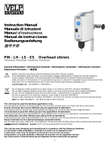 Velp Scientifica PW-LH-LS-ES Manual de usuario
-
 Velp Scientifica SP311 Manual de usuario
-
 VELP Scientific VSI-F20510531 El manual del propietario
-
 VELP Scientific VSI-SA20500465 El manual del propietario
-
VELP Scientific VLP-F20500425 El manual del propietario
-
 Velp Scientifica BOD Sensor Manual de usuario
-
 Velp Scientifica JPV Manual de usuario
-
 Velp Scientifica Vortex Wizard Manual de usuario
-
 Velp Scientifica OHS Digital Manual de usuario
-
 Velp Scientifica OHS Advanvce Manual de usuario
Otros documentos
-
 VELP Scientific F20510051 El manual del propietario
-
 VELP Scientific F20510011 El manual del propietario
-
 VELP Scientific SA20510061 El manual del propietario
-
 VELP Scientific VSI-SC20510410 El manual del propietario
-
 VELP Scientific VSI-F20500420 El manual del propietario
-
VELP Scientific F20510162 El manual del propietario
-
 VELP Scientific F20500101 El manual del propietario


