Marantec Control x.301 El manual del propietario
- Tipo
- El manual del propietario
Marantec Control x.301 es un producto que puede controlar cómodamente sus puertas, portones, persianas y otros dispositivos eléctricos a través de un smartphone o tablet. El producto es fácil de instalar y utilizar, y se puede integrar sin problemas. Le proporciona control total sobre sus dispositivos desde cualquier lugar y en cualquier momento.
Marantec Control x.301 es un producto que puede controlar cómodamente sus puertas, portones, persianas y otros dispositivos eléctricos a través de un smartphone o tablet. El producto es fácil de instalar y utilizar, y se puede integrar sin problemas. Le proporciona control total sobre sus dispositivos desde cualquier lugar y en cualquier momento.


Transcripción de documentos
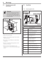
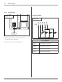
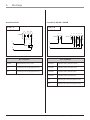
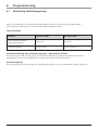
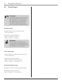
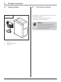
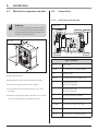
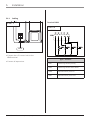
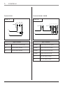
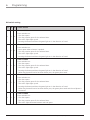
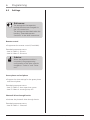
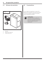
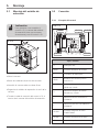
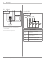
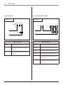
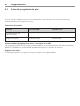
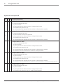
E GB D Erweiterungsmodul Expansion module Módulo de extensión Handbuch für Einbau und Bedienung Manual for installation and operation Manual para el montaje y el manejo 1. Symbolerklärung Hinweise Vorsicht! Gefahr von Personenschäden! Hier folgen wichtige Sicherheitshinweise, die zur Vermeidung von Personenschäden unbedingt beachtet werden müssen! 2. Inhaltsverzeichnis 1. Symbolerklärung . . . . . . . . . . . .2 2. Inhaltsverzeichnis . . . . . . . . . . . .2 3. Allgemeine Sicherheitshinweise 3 4. Produktübersicht . . . . . . . . . . . .5 4.1 4.2 5. Gefahr von Sachschäden! Hier folgen wichtige Sicherheitshinweise, die zur Vermeidung von Sachschäden unbedingt beachtet werden müssen! 6. Erweiterungsmodul montieren .6 Anschluss . . . . . . . . . . . . . . . .6 Programmierung . . . . . . . . . . . . .9 6.1 6.2 7. Hinweis / Tipp Montage . . . . . . . . . . . . . . . . . . .6 5.1 5.2 Achtung! Lieferumfang . . . . . . . . . . . . . .5 Leistungsmerkmale . . . . . . . . .5 Einstellung Fahrbahnregelung .9 Einstellungen . . . . . . . . . . . . .12 Anhang . . . . . . . . . . . . . . . . . . .13 EG-Konformitätserklärung . . . . . . . . .13 Kontrolle i 2 Verweis Handbuch für Einbau und Bedienung, Erweiterungsmodul D (#81439) 3. Allgemeine Sicherheitshinweise Bitte unbedingt lesen! Zielgruppe Dieses Produkt darf nur von qualifiziertem und geschultem Fachpersonal montiert, angeschlossen und in Betrieb genommen werden! Qualifiziertes und geschultes Fachpersonal im Sinne dieser Beschreibung sind Personen - mit Kenntnis der allgemeinen und speziellen Sicherheits- und Unfallverhütungsvorschriften, - mit Kenntnis der einschlägigen elektrotechnischen Vorschriften, - mit Ausbildung in Gebrauch und Pflege angemessener Sicherheitsausrüstung, - mit ausreichender Unterweisung und Beaufsichtigung durch Elektrofachkräfte, - mit der Fähigkeit, Gefahren zu erkennen, die durch Elektrizität verursacht werden können, - mit Kenntnis in der Anwendung der EN 12635 (Anforderungen an Installation und Nutzung). Gewährleistung Für eine Gewährleistung in Bezug auf Funktion und Sicherheit müssen die Hinweise in dieser Anleitung beachtet werden. Bei Missachtung der Warnhinweise können Körperverletzungen und Sachschäden auftreten. Für Schäden, die durch Nichtbeachtung der Hinweise eintreten, haftet der Hersteller nicht. Um Einbaufehler und Schäden am Gerät zu vermeiden, ist unbedingt nach den Montageanweisungen der Einbauanleitung vorzugehen. Das Produkt darf erst nach Kenntnisnahme der zugehörigen Einbau- und Bedienungsanleitung betrieben werden. Die Einbau- und Bedienungsanleitung ist dem Betreiber der Toranlage zu übergeben und aufzubewahren. Sie beinhaltet wichtige Hinweise für Bedienung, Prüfung und Wartung. Das Produkt wird gemäß den in der Hersteller- und Konformitätserklärung aufgeführten Richtlinien und Normen gefertigt. Das Produkt hat das Werk in sicherheitstechnisch einwandfreiem Zustand verlassen. Kraftbetätigte Fenster, Türen und Tore müssen vor der ersten Inbetriebnahme und nach Bedarf, jedoch jährlich mindestens einmal von einem Sachkundigen geprüft werden (mit schriftlichem Nachweis). Bestimmungsgemäße Verwendung Das Erweiterungsmodul erweitert die Steuerung x.21 um die Funktionen Funksteuerung, Ampelfunktion und Durchfahrtslichtschranke. Neben den Hinweisen in dieser Anleitung sind die allgemein gültigen Sicherheits- und Unfallvorschriften zu beachten! Es gelten unsere Verkaufs- und Lieferbedingungen. Handbuch für Einbau und Bedienung, Erweiterungsmodul D (#81439) 3 3. Allgemeine Sicherheitshinweise Bitte unbedingt lesen! Hinweise zum Einbau • Stellen Sie sicher, dass sich die anzuschließenden Anlagen (Türen etc.) mechanisch in einem einwandfreien Zustand befinden. • Vor Verkabelungsarbeiten trennen Sie das System unbedingt von der Stromversorgung. Stellen Sie sicher, dass während der Verkabelungsarbeiten die Stromversorgung unterbrochen bleibt. • Beachten Sie die örtlichen Schutzbestimmungen. • Verlegen Sie die Netz- und Steuerleitungen unbedingt getrennt. Die Betriebsspannung beträgt 24 V. Hinweise zur Reinigung Auf keinen Fall dürfen zur Reinigung eingesetzt werden: direkter Wasserstrahl, Hochdruckreiniger, Säuren oder Laugen. 4 Handbuch für Einbau und Bedienung, Erweiterungsmodul D (#81439) 4. Produktübersicht 4.1 Lieferumfang 4.1 / 1 1 4.2 Leistungsmerkmale Das Erweiterungsmodul erweitert die Steuerung x.21 um die Funktionen: - Ampelfunktion (Fahrbahnregelung) - Durchfahrtslichtschranke Hinweis: 2 Um das Erweiterungsmodul an der Steuerung x.21 betreiben zu können, muss eine 2-Draht-Lichtschranke angeschlossen und aktiviert sein. 3 1 2 3 Gehäuse Erweiterungsmodul Schraubenset Handbuch für Einbau und Bedienung, Erweiterungsmodul D (#81439) 5 5. Montage 5.1 Erweiterungsmodul montieren Hinweis: 5.2 Anschluss 5.2.1 Steuerungsübersicht 5.2.1 / 1 Um einen Anschluss an die Steuerung x.21 zu gewährleisten, muss das Gehäuse des Erweiterungsmoduls direkt neben die Steuerung x.21 montiert werden. B XB99 A XH14 XH19B 5.1 / 1 XB48 A Art / Funktion • Öffnen Sie das Gehäuse. • Nehmen Sie die Abdeckungen (A) an beiden Gehäusen heraus. • Schrauben Sie das Gehäuse an einen festen Untergrund. • Stecken Sie das Erweiterungsmodul auf die Schiene im Gehäuse. • Führen Sie das Anschlusskabel aus der Steuerung x.21 in das Gehäuse Erweiterungsmodul. 6 C D E F XH19A A Dippschalter XB99 Anschluss Bedienelement B Entriegelungsschieber XB48 Anschlussbuchse für Steuerung x.21 C Anzeige Signalleuchte Ausfahrt Rot/Grün D Anzeige Signalleuchte Einfahrt Rot/Grün E Anzeige Lichtschranke ZU F Anzeige Endposition AUF / ZU XH19A Anschluss Signalleuchten EIN XH19B Anschluss Signalleuchten XH14 Anschluss Wischimpuls Handbuch für Einbau und Bedienung, Erweiterungsmodul D (#81439) 5. Montage 5.2.2 Verkabelung Anschluss XB99 5.2.2 / 1 5.2.2 / 2 M07E026 XB48 • Schließen Sie die Steuerung x.21 an die Anschlussbuchse XB48 an. Art / Funktion • Schließen Sie alle Erweiterungen an. SB31 Schaltkontakt Vorrang SB33 Schaltkontakt Tor AUF SB36 Impulstaster Einfahrt SB37 Impulstaster Ausfahrt Handbuch für Einbau und Bedienung, Erweiterungsmodul D (#81439) 7 5. Montage Anschluss XH14 Anschluss XH19A / XH19B 5.2.2 / 3 5.2.2 / 4 M07E026 H1 42A M07E026 42B H1 94 H1 92A 94A 92B 94B -XH14 -HH92B A1 -HH94B L1 L1 -HH94A -XH19B -HH92A -XH19A -KH42 A2 N N Art / Funktion 8 Art / Funktion KH42 Zentralrelais 3-min.-Licht HH92A Signalleuchte Ausfahrt Grün L1 Bauseitige Versorgungsspannung HH92B Signalleuchte Einfahrt Grün N Bauseitige Versorgungsspannung HH94A Signalleuchte Ausfahrt Rot HH94B Signalleuchte Einfahrt Rot L1 Bauseitige Versorgungsspannung N Bauseitige Versorgungsspannung Handbuch für Einbau und Bedienung, Erweiterungsmodul D (#81439) 6. Programmierung 6.1 Einstellung Fahrbahnregelung Wenn eine Zeitschaltuhr am Anschluss XB99 angeschlossen ist, können mit den Dippschaltern verschiedene Einstellungen für die Fahrbahnregelung gewählt werden. Tasteranschlüsse Funktion Anschluss SB36 Anschluss SB37 Keine Fahrbahnregelung (Standardeinstellung) Taster AUF Taster ZU Fahrbahnregelung Taster Einfahrt Taster Ausfahrt Standardeinstellung (keine Fahrbahnregelung – Dippschalter auf 000) Die Anschlüsse XH19A, XH19B und XH14 sind für potentialfreie Endtastermeldungen AUF und ZU verwendbar. Der Anschluss XB99 kann für einen Impulstaster verwendet werden. Fahrbahnregelung Die unterschiedlichen Einstellungen der Fahrbahnregelungen sind in nachstehender Tabelle aufgeführt. Handbuch für Einbau und Bedienung, Erweiterungsmodul D (#81439) 9 6. Programmierung Dippschaltereinstellung S1 1 0 1 0 1 10 S2 0 1 1 0 0 S3 Fahrbahnregelung 0 Zeitschaltuhr an SB33 Zeitschaltung schaltet ein: - Das Tor öffnet sich. - Das Tor bleibt für die gewählte Zeitspanne offen. - Die Ampeln leuchten rot. - Tasterbetätigung gibt Grünlicht in Fahrtrichtung. 0 Zeitschaltuhr an SB33 Zeitschaltung schaltet ein: - Tor öffnet bei Betätigung eines Tasters. - Das Tor bleibt für die gewählte Zeitspanne offen. - Die Ampeln leuchten rot. - Tasterbetätigung gibt Grünlicht in Fahrtrichtung. 0 Zeitschaltuhr an SB33 Zeitschaltung schaltet ein: - Das Tor öffnet sich. - Das Tor bleibt für die gewählte Zeitspanne offen. - Die Ampeln leuchten rot. - Tasterbetätigung gibt Grünlicht in Fahrtrichtung. - Beim Verlassen der Lichtschranke wird die Grünzeit beendet. 1 Zeitschaltuhr an SB33 Zeitschaltung schaltet ein: - Das Tor öffnet sich. - Das Tor bleibt für die gewählte Zeitspanne offen. - Die Ampeln leuchten rot. - Tasterbetätigung gibt Grünlicht in Fahrtrichtung. - Beim Verlassen der Lichtschranke wird die Grünzeit beendet und die Rotzeit verkürzt. 1 Zeitschaltuhr an SB33 Zeitschaltung schaltet ein: - Das Tor öffnet sich. - Das Tor bleibt für die gewählte Zeitspanne offen. - Die Ampeln leuchten rot und grün im Wechsel. Handbuch für Einbau und Bedienung, Erweiterungsmodul D (#81439) 6. S1 Programmierung S2 S3 0 1 1 1 1 1 Fahrbahnregelung Zeitschaltuhr an SB33 (Zeitschaltung mit zwei Zeitschaltuhren) Zeitschaltung 1 schaltet ein: - Das Tor öffnet sich. - Das Tor bleibt für die gewählte Zeitspanne offen. - Ein- / Ausfahrt 1 leuchtet dauerhaft grün. - Ein- / Ausfahrt 2 leuchtet dauerhaft rot. - Ein- / Ausfahrt 2 bekommt grün durch Tasterbetätigung. Zeitschaltuhr an SB31 (Zeitschaltung mit zwei Zeitschaltuhren) Zeitschaltung 2 schaltet ein: - Das Tor öffnet sich. - Das Tor bleibt für die gewählte Zeitspanne offen. - Ein- / Ausfahrt 1 leuchtet dauerhaft rot. - Ein- / Ausfahrt 2 leuchtet dauerhaft grün. - Ein- / Ausfahrt 1 bekommt grün durch Tasterbetätigung. - Handbuch für Einbau und Bedienung, Erweiterungsmodul D (#81439) 11 6. Programmierung 6.2 Einstellungen i Verweis: Die Einstellungen für die Funktionen des Erweiterungsmoduls werden in der Steuerung x.21 vorgenommen. Die Einstellungen sind im Kapitel “Erweiterte Antriebsfunktionen” der Antriebsanleitung beschrieben. Funksteuerung • Programmieren Sie die Funksteuerung (falls vorhanden). Erweitertes Programmiermenü: - Ebene 4 / Menü 1: Einfahrt - Ebene 4 / Menü 2: Ausfahrt Hinweis: Bei Anschluss des Erweiterungsmoduls ändert sich die Programmierungsbelegung der Antriebssteuerung auf “Einfahrt” und “Ausfahrt”. Grün- und Rotzeit • Programmieren Sie Zeiteinstellungen für die Grün- und Rotzeit. Erweitertes Programmiermenü: - Ebene 3 / Menü 3: Toraufzeit grün - Ebene 3 / Menü 4: Vorwarnzeit rot Durchfahrtslichtschranke • Aktivieren Sie die Durchfahrtslichtschranke. Erweitertes Programmiermenü: - Ebene 8 / Menü 1: Lichtschranke 12 Handbuch für Einbau und Bedienung, Erweiterungsmodul D (#81439) 7. Anhang EG-Konformitätserklärung Hiermit erklären wir, dass das nachfolgend bezeichnete Produkt aufgrund seiner Konzipierung und Bauart sowie in der von uns in Verkehr gebrachten Ausführung den einschlägigen grundlegenden Sicherheits- und Gesundheitsanforderungen der EG-Richtlinie Elektromagnetische Verträglichkeit, der Maschinen-Richtlinie und der Niederspannungsrichtlinie entspricht. Bei einer nicht mit uns abgestimmten Änderung der Produkte verliert diese Erklärung ihre Gültigkeit. Produkt: Einschlägige EG-Richtlinien: EG-Richtlinie Elektromagnetische Verträglichkeit (89/336/EWG), Maschinen-Richtlinie (98/37/EWG) und Niederspannungsrichtlinie (73/23/EWG und 93/68/EWG). Angewandte harmonisierte Normen, insbesondere: EN 292-1 / EN 61000-6-2 / EN 61000-6-3 / EN 55014 / EN 61000-3-2 / EN 61000-3-3 / EN 60335-1 / EN 60335-2-95 / EN 12445 / EN 12453 / EN 300220-1 / EN 301489-3 / ETS 300683 Datum / Unterschrift Handbuch für Einbau und Bedienung, Erweiterungsmodul D (#81439) 13 1. Meaning of symbols Advice Caution! Danger of personal injury! The following safety advice must be observed at all times so as to avoid personal injury! Table of contents 1. Meaning of symbols . . . . . . . . .14 2. Table of contents . . . . . . . . . . .14 3. General safety advice . . . . . . . .15 4. Product overview . . . . . . . . . . .17 4.1 4.2 5. Attention! Danger of material damage! The following safety advice must be observed at all times so as to avoid material damage! Advice / Tip 2. Installation . . . . . . . . . . . . . . . .18 5.1 5.2 6. Mount the expansion module 18 Connection . . . . . . . . . . . . . .18 Programming . . . . . . . . . . . . . .21 6.1 6.2 7. Supply package . . . . . . . . . . .17 Performance Features . . . . . .17 Adjustment of traffic control .21 Settings . . . . . . . . . . . . . . . . .24 Attachment . . . . . . . . . . . . . . . .25 EC Declaration of Conformity . . . . . . .25 Check i 14 Reference Manual for installation and operation, Expansion module GB (#81439) 3. General safety advice Please read carefully! Target group This operator system may only be installed, connected and put into operation by qualified and trained professionals! Qualified and trained specialist personnel are persons - who have knowledge of the general and special safety regulations, - who have knowledge of the relevant electro-technical regulations, - with training in the use and maintenance of suitable safety equipment, - who are sufficiently trained and supervised by qualified electricians, - who are able to recognise the particular hazards involved when working with electricity, - with knowledge regarding applications of the EN 12635 standard (installation and usage requirements). Warranty For an operations and safety warranty, the advice in this instruction manual has to be observed. Disregarding these warnings may lead to personal injury or material damage. If this advice is disregarded, the manufacturer will not be liable for damages that might occur. To avoid installation errors and damage to the device, it is imperative that the installation instructions are followed. The product may only be operated after reading these installation and operating instructions. The installation and operating instructions are to be given to the door system user, who must keep them safe. They contain important advice for operation, checks and maintenance. This item is produced according to the directives and standards mentioned in the Manufacturer's Declaration and in the Declaration of Conformity. The product has left the factory in perfect condition with regard to safety. Power-operated windows, doors and gates must be checked by an expert (and this must be documented) before they are put into operation and thereafter as required, but at least once a year. Correct use The expansion module expands the x.21 control unit by the functions: radio control, traffic light function and photocell drive-through barrier. Beside the advice in these instructions, please observe the general safety and accident prevention regulations! Our sales and supply terms and conditions are effective. Manual for installation and operation, Expansion module GB (#81439) 15 3. General safety advice Please read carefully! Installation tips • Ensure that the devices to be connected (doors etc.) are in a mechanically faultless state. • Before commencing cabling works it is very important to disconnect the system from the electricity supply. Ensure that the electricity supply remains disconnected throughout the cabling works. • Adhere to the local protection regulations. • Lay the electricity supply cables and control cables; these MUST be laid separately. The operating voltage is 24 V. Cleaning tips Never use water jets, high pressure cleaners, acids or bases for cleaning. 16 Manual for installation and operation, Expansion module GB (#81439) 4. Product overview 4.1 Supply package 4.1 / 1 1 4.2 Performance Features The expansion module expands the x.21 control unit by the functions: - traffic light functions (traffic control) - photocell drive-through barrier Advice: 2 In order to operate the expansion module at the x.21 control unit, a 2-wire photocell barrier has to be connected and activated. 3 1 2 3 Housing Expansion module Screw set Manual for installation and operation, Expansion module GB (#81439) 17 5. Installation 5.1 Mount the expansion module Advice: 5.2 Connection 5.2.1 Overview of control unit 5.2.1 / 1 To ensure a proper connection to the x.21 controls, the expansion module housing must be mounted right next to the x.21 control unit. B XB99 A XH14 XH19B 5.1 / 1 XB48 C D E F XH19A A Type / function A DIP switch XB99 Connection of control element B Release slide XB48 Connection of x.21 control unit C Display signal light Drive-out red/green D Display signal light Drive-in red/green E Display photocell CLOSED F Display OPEN/CLOSED end position XH19A Connection signal lights ON XH19B Connection of signal lights XH14 Connection of wiping impulse • Open the housing. • Remove the covers (A) from both housings. • Screw the housing onto a firm surface. • Fit the expansion module onto the rail in the housing. • Feed the connection cable from the x.21 control unit into the expansion module housing. 18 Manual for installation and operation, Expansion module GB (#81439) 5. Installation 5.2.2 Cabling Terminal XB99 5.2.2 / 1 5.2.2 / 2 M07E026 XB48 • Connect the x.21 control unit to the XB48 terminal. Type / function • Connect all expansions. SB31 Switching contact priority SB33 Switching contact door OPEN SB36 Impulse button, drive-in SB37 Impulse button, drive-out Manual for installation and operation, Expansion module GB (#81439) 19 5. Installation Terminal XH14 Terminal XH19A / XH19B 5.2.2 / 3 5.2.2 / 4 M07E026 H1 42A 42B M07E026 H1 94 H1 92A 94A 92B 94B -XH14 -HH92B A1 -HH94B L1 L1 -HH94A -XH19B -HH92A -XH19A A2 -KH42 N N Type / function Type / function KH42 Central relay, 3 minute light HH92A Signal light drive-out green L1 On-site supply voltage HH92B Signal light drive-in green N On-site supply voltage HH94A Signal light drive-out red HH94B Signal light drive-in red L1 On-site supply voltage N On-site supply voltage 20 Manual for installation and operation, Expansion module GB (#81439) 6. Programming 6.1 Adjustment of traffic control If a timer is connected to terminal XB99, different settings for the traffic control system can be selected with the DIP switches. Button connections Function Terminal SB36 Terminal SB37 no traffic control (default) OPEN button CLOSE button Traffic control DRIVE-IN button DRIVE-OUT button Standard setting (no traffic control – DIP switches set to 000) Terminals XH19A, XH19B and XH14 can be used for potential-free limit switch messages, OPEN and CLOSE. Terminal XB99 can be used for an impulse button. Traffic control The different traffic control settings are listed in the table below. Manual for installation and operation, Expansion module GB (#81439) 21 6. Programming DIP switch setting S1 1 0 1 0 1 22 S2 0 1 1 0 0 S3 Traffic control 0 Timer at SB33 Timer switches on: - The door opens. - The door remains open for the selected time. - The traffic lights light up red. - Pressing the button switches the green light on in the direction of travel. 0 Timer at SB33 Timer switches on: - Door opens when a button is pushed. - The door remains open for the selected time. - The traffic lights light up red. - Pressing the button switches the green light on in the direction of travel. 0 Timer at SB33 Timer switches on: - The door opens. - The door remains open for the selected time. - The traffic lights light up red. - Pressing the button switches the green light on in the direction of travel. - When the photocell barrier has been driven past, the green phase ends. 1 Timer at SB33 Timer switches on: - The door opens. - The door remains open for the selected time. - The traffic lights light up red. - Pressing the button switches the green light on in the direction of travel. - When the photocell barrier has been driven past, the green phase ends and the red phase is shortened. 1 Timer at SB33 Timer switches on: - The door opens. - The door remains open for the selected time. - The traffic lights alternate between red and green. Manual for installation and operation, Expansion module GB (#81439) 6. S1 Programming S2 S3 0 1 1 1 1 1 Traffic control Timer at SB33 (Timed switching with two timers) Time switch 1 switches on: - The door opens. - The door remains open for the selected time. - Drive-in/drive out 1 lights continuously green. - Drive-in/drive out 2 lights continuously red. - Drive-in/drive out 2 gets green light when button is pressed. Timer at SB33 (Timed switching with two timers) Time switch 2 switches on: - The door opens. - The door remains open for the selected time. - Drive-in/drive out 1 lights continuously red. - Drive-in/drive out 2 lights continuously green. - Drive-in/drive out 1 gets green light when button is pressed. - Manual for installation and operation, Expansion module GB (#81439) 23 6. Programming 6.2 Settings i Reference: The settings for the expansion module functions are changed via the x.21 control unit. The settings are described under the heading “Extended operator functions” in the drive instructions. Remote control • Programme the remote control (if available). Extended programme menu: - Level 4 / Menu 1: Drive-in - Level 4 / Menu 2: Drive-out Advice: When the expansion module is connected, the programming configuration of the drive controls changes to “Drive-in” and “Driveout”. Green phase and red phase • Program the time settings for the green phase and the red phase. Extended programme menu: - Level 3 / Menu 3: door open time, green - Level 3 / Menu 4: warning time, red Photocell drive-through barrier • Activate the photocell drive-through barrier. Extended programme menu: - Level 8 / Menu 1: Photocell 24 Manual for installation and operation, Expansion module GB (#81439) 7. Attachment EC Declaration of Conformity We hereby declare that the product sold by us and mentioned below corresponds in its design, construction and version to the relevant and basic health and safety requirements of the following EC regulations: EMC Directive, Machinery Directive and Low Voltage Directive. Product changes made without our consent will render this Declaration void. Product: Relevant EC Regulations: - EC EMC Directive (89/336/EWG), - Machinery Directive (98/37/EWG) and - Low Voltage Directive (73/23/EWG und 93/68/EWG). Applied harmonised standards, in particular: EN 292-1 / EN 61000-6-2 / EN 61000-6-3 / EN 55014 / EN 61000-3-2 / EN 61000-3-3 / EN 60335-1 / EN 60335-2-95 / EN 12445 / EN 12453 / EN 300220-1 / EN 301489-3 / ETS 300683 Date / Signature Manual for installation and operation, Expansion module GB (#81439) 25 1. Explicación de los símbolos Indicaciones ¡Precaución! ¡Peligro de daños a personas! Aquí aparecen indicaciones importantes de seguridad que tienen que ser observadas de modo estrictamente necesario con objeto de evitar daños personales. 2. Índice 1. Explicación de los símbolos . . .26 2. Índice . . . . . . . . . . . . . . . . . . . . .26 3. Indicaciones generales de seguridad . . . . . . . . . . . . . . . . .27 4. Sinopsis del producto . . . . . . . .29 4.1 4.2 5. ¡Peligro de daños materiales! Aquí aparecen indicaciones importantes de seguridad que tienen que ser observadas de modo estrictamente necesario con objeto de evitar daños materiales. Indicación / Consejo Montaje . . . . . . . . . . . . . . . . . . .30 5.1 ¡Atención! 5.2 6. Montaje del módulo de extensión . . . . . . . . . . . . . . . .30 Conexión . . . . . . . . . . . . . . . .30 Programación . . . . . . . . . . . . . .33 6.1 6.2 7. Volumen de suministro . . . . .29 Características . . . . . . . . . . . .29 Ajuste de la regulación de pista . . . . . . . . . . . . . . . . . . .33 Ajustes . . . . . . . . . . . . . . . . .36 Apéndice . . . . . . . . . . . . . . . . . .37 Declaración de conformidad CE . . . . .37 Controles i 26 Referencia Manual para el montaje y el manejo, Módulo de extensión E (#81439) 3. Indicaciones generales de seguridad ¡Por favor, lea lo siguiente en cualquier caso! Grupo de destino ¡Este automatismo tiene que ser montado, conectado y puesto en funcionamiento exclusivamente por especialistas cualificados e instruidos! Especialistas cualificados e instruidos, en el sentido de estas instrucciones, son personas - con conocimiento de las prescripciones generales y especiales de seguridad y de prevención de accidentes, - con conocimiento de las prescripciones electrotécnicas pertinentes, - con formación en el uso y el cuidado de los equipamientos adecuados de seguridad, - con una instrucción y dirección suficiente por parte de electricistas profesionales, - con la capacidad de reconocer los peligros que pueden ser causados por la electricidad, - con conocimientos de la aplicación práctica de EN 12635 (Requerimientos a la instalación y al empleo). Garantía Para que sea efectiva la garantía relativa al funcionamiento y a la seguridad, es necesario que se observen las indicaciones de estas instrucciones. En caso de no observancia de las indicaciones de advertencia pueden producirse lesiones corporales y daños materiales. El fabricante no se hace responsable de los daños que se produzcan como consecuencia de la no observancia de las indicaciones. Con objeto de evitar errores de montaje y daños en el aparato es estrictamente necesario proceder conforme a las indicaciones de las instrucciones de montaje. Sólo se debe poner en funcionamiento el producto después de haber leído las instrucciones de montaje y de manejo correspondientes. Las instrucciones de montaje y de manejo se le tienen que entregar al usuario de la instalación de la puerta, el cual ha de guardarlas debidamente. Ellas contienen importantes indicaciones para el manejo, el control y el mantenimiento. El producto se fabrica en conformidad con las directivas y normas aducidas en la declaración del fabricante y en la declaración de conformidad. El producto ha salido de la fábrica en un estado impecable en lo que respecta a la técnica de seguridad. Es necesario que un perito inspeccione puertas, portones y ventanas accionadas mediante motor antes de la primera puesta en funcionamiento y siempre que ello sea preciso, pero como mínimo una vez al año (con certificación escrita). Utilización reglamentaria Con el módulo de extensión, el control x.21 dispone adicionalmente de las funciones de control por radio, de la función de semáforo y de la barrera fotoeléctrica de paso. ¡Además de las indicaciones contenidas en estas instrucciones, hay que observar también las prescripciones generales vigentes para la seguridad y para la prevención de accidentes! Rigen nuestras condiciones de venta y de suministro. Manual para el montaje y el manejo, Módulo de extensión E (#81439) 27 3. Indicaciones generales de seguridad ¡Por favor, lea lo siguiente en cualquier caso! Indicaciones para el montaje • Asegúrese de que las instalaciones que se van a conectar (puertas etc.) se encuentran en un estado mecánicamente perfecto. • Antes de realizar trabajos de cableado, es estrictamente necesario cortar el suministro eléctrico del sistema. Asegúrese de que la corriente se mantiene cortada mientras que se llevan a cabo los trabajos de cableado. • Observe las normativas locales de protección. • ¡Es estrictamente necesario tender por separado las líneas de red y de control! La tensión de servicio es de 24 V. Indicaciones para la limpieza Para la limpieza no se debe emplear en ningún caso: chorro de agua directo, equipo de limpieza a alta presión, ácidos o lejías. 28 Manual para el montaje y el manejo, Módulo de extensión E (#81439) 4. Sinopsis del producto 4.1 Volumen de suministro 4.1 / 1 1 4.2 Características Con el módulo de extensión, el control x.21 dispone de las siguientes funciones adicionales: - Función de semáforo (regulación de pista) - Barrera fotoeléctrica de paso Indicación: 2 Para poder operar el módulo de extensión con el control x.21 tiene que estar conectada y activada una barrera fotoeléctrica de dos conductores. 3 1 2 3 Carcasa Módulo de extensión Juego de tornillos Manual para el montaje y el manejo, Módulo de extensión E (#81439) 29 5. Montaje 5.1 Montaje del módulo de extensión Indicación: 5.2 Conexión 5.2.1 Sinopsis del control 5.2.1 / 1 Para garantizar una conexión al control x.21, la carcasa del módulo de extensión tiene que montarse directamente junto al control x.21. B XB99 A XH14 XH19B 5.1 / 1 XB48 C D E F XH19A A Tipo / Función A Interruptor DIP XB99 Conexión elemento de mando B Corredera de desbloqueo XB48 Hembrilla de conexión para el control x.21 • Atornille la carcasa sobre una base firme. C Indicación lámpara de señales Salida rojo / verde • Enganche el módulo de expansión al carril de la carcasa. D Indicación lámpara de señales Entrada rojo / verde • Tienda el cable de conexión del control x.21 al interior de la carcasa del módulo de extensión. E Indicación barrera fotoeléctrica CERRADO F Indicación posición final ABIERTO / CERRADO XH19A Conexión lámparas de señal CONECTADAS XH19B Conexión de lámparas de señal XH14 Conexión impulso transitorio • Abra la carcasa. • Retire las cubiertas (A) de las dos carcasas. 30 Manual para el montaje y el manejo, Módulo de extensión E (#81439) 5. Montaje 5.2.2 Cableado Conexión XB99 5.2.2 / 1 5.2.2 / 2 M07E026 XB48 • Conecte el control x.21 a la hembrilla de conexión XB48. Tipo / Función • Conecte todas las expansiones. SB31 Contacto de conmutación preferencia SB33 Contacto de conmutación puerta ABIERTO SB36 Pulsador de impulsos entrada SB37 Pulsador de impulsos salida Manual para el montaje y el manejo, Módulo de extensión E (#81439) 31 5. Montaje Conexión XH14 Conexión XH19A / XH19B 5.2.2 / 3 5.2.2 / 4 M07E026 H1 42A M07E026 42B H1 94 H1 92A 94A 92B 94B -XH14 -HH92B A1 -HH94B L1 L1 -HH94A -XH19B -HH92A -XH19A -KH42 A2 N N Tipo / Función Tipo / Función KH42 Relé central 3 min. luz HH92A Lámpara de señales salida verde L1 Tensión de alimentación de parte de la obra HH92B Lámpara de señales entrada verde HH94A Lámpara de señales salida rojo N Tensión de alimentación de parte de la obra HH94B Lámpara de señales entrada rojo L1 Tensión de alimentación de parte de la obra N Tensión de alimentación de parte de la obra 32 Manual para el montaje y el manejo, Módulo de extensión E (#81439) 6. Programación 6.1 Ajuste de la regulación de pista Si en la conexión XB99 hay conectado un temporizador, con el interruptor DIP es posible seleccionar diversos ajustes para la regulación de pista. Conexiones de pulsador Función Conexión SB36 Conexión SB37 Sin regulación de pista (Ajuste estándar) Pulsador ABIERTO Pulsador CERRADO Regulación de pista Pulsador entrada Pulsador salida Ajuste estándar (sin regulación de pista – interruptor DIP a 000) Las conexiones XH19A, XH19B y XH14 pueden emplearse para avisos de palpador final libre de potencial ABIERTO y CERRADO. La conexión XB99 puede empelarse para un pulsador de impulsos. Regulación de pista Los diferentes ajustes de la regulación de pista se aducen en la siguiente tabla. Manual para el montaje y el manejo, Módulo de extensión E (#81439) 33 6. Programación Ajustes del interruptor DIP S1 1 0 1 0 1 34 S2 0 1 1 0 0 S3 Regulación de pista 0 Temporizador en SB33 La conexión temporal se activa: - La puerta se abre. - La puerta permanece abierta durante el tiempo seleccionado. - Los semáforos se ponen en rojo. - Un accionamiento del pulsador da luz verde en la dirección de la marcha. 0 Temporizador en SB33 La conexión temporal se activa: - La puerta se abre al accionar el pulsador. - La puerta permanece abierta durante el tiempo seleccionado. - Los semáforos se ponen en rojo. - Un accionamiento del pulsador da luz verde en la dirección de la marcha. 0 Temporizador en SB33 La conexión temporal se activa: - La puerta se abre. - La puerta permanece abierta durante el tiempo seleccionado. - Los semáforos se ponen en rojo. - Un accionamiento del pulsador da luz verde en la dirección de la marcha. - Al abandonar la barrera fotoeléctrica finaliza el tiempo de verde. 1 Temporizador en SB33 La conexión temporal se activa: - La puerta se abre. - La puerta permanece abierta durante el tiempo seleccionado. - Los semáforos se ponen en rojo. - Un accionamiento del pulsador da luz verde en la dirección de la marcha. - Al abandonar la barrera fotoeléctrica finaliza el tiempo de verde y se acorta el tiempo de rojo. 1 Temporizador en SB33 La conexión temporal se activa: - La puerta se abre. - La puerta permanece abierta durante el tiempo seleccionado. - Los semáforos se ponen en rojo y en verde alternativamente. Manual para el montaje y el manejo, Módulo de extensión E (#81439) 6. S1 Programación S2 S3 0 1 1 1 1 1 Regulación de pista Temporizador en SB33 (Conexión temporal con dos temporizadores) La conexión temporal 1 se activa: - La puerta se abre. - La puerta permanece abierta durante el tiempo seleccionado. - Entrada / salida 1 se ilumina permanentemente en verde. - Entrada / salida 2 se ilumina permanentemente en rojo. - La entrada / salida 2 se pone verde accionando el pulsador. Temporizador en SB31 (Conexión temporal con dos temporizadores) La conexión temporal 2 se activa: - La puerta se abre. - La puerta permanece abierta durante el tiempo seleccionado. - Entrada / salida 1 se ilumina permanentemente en rojo. - Entrada / salida 2 se ilumina permanentemente en verde. - La entrada / salida 1 se pone verde accionando el pulsador. - Manual para el montaje y el manejo, Módulo de extensión E (#81439) 35 6. Programación 6.2 Ajustes i Referencia: Los ajustes para las funciones del módulo de extensión se llevan a cabo en el control x.21. Los ajustes se describen en el capítulo “Funciones ampliadas de operación” de las instrucciones. Radiocontrol • Programe el radiocontrol (si lo hubiera). Menú de programación ampliado: - Nivel 4 / Menú 1: Entrada - Nivel 4 / Menú 2: Salida Indicación: Al conectar el módulo de expansión cambia la asignación de programación del control del operador a “Entrada” y “Salida”. Tiempo de verde y de rojo • Programe los ajustes de tiempo para verde y para rojo. Menú de programación ampliado: - Nivel 3 / Menú 3: Tiempo de apertura de la puerta verde - Nivel 3 / Menú 4: Tiempo de preadvertencia rojo Barrera fotoeléctrica de paso • Active la barrera fotoeléctrica de paso. Menú de programación ampliado: - Nivel 8 / Menú 1: Barrera fotoeléctrica 36 Manual para el montaje y el manejo, Módulo de extensión E (#81439) 7. Apéndice Declaración de conformidad CE Por la presente declaramos que el producto especificado a continuación, tanto en su diseño y modo de construcción como en el modelo lanzado por nosotros al mercado, cumple con los requerimientos básicos pertinentes de seguridad y de salud de las directiva comunitaria de compatibilidad electromagnética, de la directiva de máquinas y de la directiva de baja tensión. Esta declaración pierde su validez en caso de que se lleven a cabo modificaciones de los productos que no hayan sido acordadas con nosotros. Producto: Directivas CE pertinentes: Directiva CE de compatibilidad electromagnética (89/336/EWG), Directiva de máquinas (98/37/EWG) Directiva de baja tensión (73/23/EWG und 93/68/EWG) Normas armonizadas aplicadas, especialmente: EN 292-1 / EN 61000-6-2 / EN 61000-6-3 / EN 55014 / EN 61000-3-2 / EN 61000-3-3 / EN 60335-1 / EN 60335-2-95 / EN 12445 / EN 12453 / EN 300220-1 / EN 301489-3 / ETS 300683 Fecha / Firma Manual para el montaje y el manejo, Módulo de extensión E (#81439) 37 38 Manual para el montaje y el manejo, Módulo de extensión E (#81439) Manual para el montaje y el manejo, Módulo de extensión E (#81439) 39 Urheberrechtlich geschützt. Nachdruck, auch auszugsweise, nur mit unserer Genehmigung. Änderungen, die dem technischen Fortschritt dienen, vorbehalten. English Copyright. No part of this manual may be reproduced without our prior consent. Subject to changes which are in the interest of technical improvements. Español Propiedad intelectual. Reimpresión, aunque se trate sólo de extractos, sólo con nuestro permiso. Sujeto a modificaciones en función del progreso técnico. 81439 Stand: 08.2009 #81 439 1 - D/GB/E/KD 36-1-0163 - M - 0.5 - 0407 Deutsch-
 1
1
-
 2
2
-
 3
3
-
 4
4
-
 5
5
-
 6
6
-
 7
7
-
 8
8
-
 9
9
-
 10
10
-
 11
11
-
 12
12
-
 13
13
-
 14
14
-
 15
15
-
 16
16
-
 17
17
-
 18
18
-
 19
19
-
 20
20
-
 21
21
-
 22
22
-
 23
23
-
 24
24
-
 25
25
-
 26
26
-
 27
27
-
 28
28
-
 29
29
-
 30
30
-
 31
31
-
 32
32
-
 33
33
-
 34
34
-
 35
35
-
 36
36
-
 37
37
-
 38
38
-
 39
39
-
 40
40


Marantec Control x.301 El manual del propietario
- Tipo
- El manual del propietario
Marantec Control x.301 es un producto que puede controlar cómodamente sus puertas, portones, persianas y otros dispositivos eléctricos a través de un smartphone o tablet. El producto es fácil de instalar y utilizar, y se puede integrar sin problemas. Le proporciona control total sobre sus dispositivos desde cualquier lugar y en cualquier momento.
en otros idiomas
Artículos relacionados
-
Marantec EM 131 El manual del propietario
-
Marantec EM 171 El manual del propietario
-
-
Marantec EM 113 El manual del propietario
-
Marantec EM 110 El manual del propietario
-
-
-
Marantec EM 111 El manual del propietario
-
-
Marantec Comfort 390 plus El manual del propietario