Yamaha RX-A800 El manual del propietario
- Categoría
- Receptores AV
- Tipo
- El manual del propietario

Owner’s Manual
AV Receiver English for Canada

En 2
CONTENTS
INTRODUCTION
Features and capabilities ...................................................4
Using the TV OSD to operate the unit .............................5
View or modify content for the current input source
<Content window> ...........................................................5
Configuring settings for this unit
<ON SCREEN menu>......................................................5
Adjust settings for each input source
<OPTION menu> ............................................................. 6
About this manual............................................................. 7
Supplied accessories......................................................... 7
Part names and functions..................................................8
Front panel........................................................................8
Rear panel.........................................................................9
Front panel display .........................................................10
Remote control ...............................................................11
On-screen display ........................................................... 12
CONNECTIONS
Connecting speakers ........................................................13
Speaker channels and functions...................................... 13
Speaker layout ................................................................14
Connecting speakers and subwoofer .............................. 17
Connecting external components....................................21
Cable plugs and jacks .....................................................21
Connecting a TV monitor............................................... 22
Connecting BD/DVD players and other devices............25
Connecting game consoles ............................................. 29
Connecting a multi-format player
or an external decoder .................................................... 29
Connecting an external amplifier ................................... 30
Connecting a SCENE link
playback-compatible device ...........................................30
Using the Trigger function to link
external component power.............................................. 31
Connecting audio/video recording devices.....................31
Connecting the FM/AM antennas .................................. 32
Setting up the speaker parameters automatically
(YPAO).............................................................................. 33
PLAYBACK
Basic playback procedure ............................................... 41
Adjusting high/low-frequency sound (Tone control) ..... 42
Changing input settings with a single key
(SCENE function) ............................................................ 43
Registering input sources/sound program/
HDMI OUT .................................................................... 43
Enjoying the desired sound field effect.......................... 43
Selecting sound programs and sound decoders.............. 43
Sound programs.............................................................. 47
Using the TV display to control this unit....................... 49
Basic operations via the TV screen display ................... 49
Configuring settings specific to
an individual input source (OPTION menu)................. 51
OPTION menu display and setup................................... 51
OPTION menu ............................................................... 52
Confirming and operating input sources
from the Content window ............................................... 55
Displaying the Content window on the TV screen......... 55
Switching the display between the Now Playing view
and the Content browse view ......................................... 55
FM/AM tuning ................................................................. 56
Selecting a frequency for reception (Normal tuning)..... 56
Confirming and operating the FM/AM tuner
from the Content window............................................... 58
Playing back tunes from your iPod™/iPhone™ ........... 60
Connecting the Universal Dock for iPod/iPhone ........... 60
Controlling an iPod™/iPhone™ .................................... 60
Playing iPod/iPhone from the menu screen
(Menu browse control) ................................................... 61
Operating basic playback functions
via the remote control (Simple remote control) ............. 63
Playing iPod™/iPhone™
with wireless connection................................................ 63
Playing back tunes from Bluetooth™ components ...... 65
Connecting a Yamaha Bluetooth
wireless audio receiver................................................... 65
Pairing Bluetooth™ components ................................... 65
Using Bluetooth™ components ..................................... 66

En 3
SETUP
Configuring input sources (Input menu) .......................67
Configuring input sources .............................................. 67
Input menu......................................................................68
Editing the SCENE function (SCENE menu) ...............71
Editing a scene................................................................71
SCENE menu..................................................................72
Setting sound program parameters
(Sound Program menu) ...................................................74
Editing sound programs..................................................74
CINEMA DSP parameters ............................................. 75
Parameters usable in certain sound programs ................77
Parameters usable in surround decoder .......................... 78
Setting various functions (Setup menu) .........................79
Operating the Setup menu ..............................................79
Setup menu .....................................................................80
Manages settings for speakers ........................................80
Setting the audio output function of this unit .................84
Setting this unit’s video output function.........................85
Setting HDMI functions .................................................86
Setting this unit’s multi-zone function ...........................89
Making the receiver easier to use ................................... 89
Language ........................................................................ 92
Confirming information of this unit
(Information menu) .........................................................93
Selecting information .....................................................93
Controlling other components
with the remote control.................................................... 94
Keys connecting external components ...........................94
Default remote control code settings.............................. 95
Registering remote control codes
for external component operations .................................95
Resetting all remote control codes .................................96
Extended functionality that can be configured
as needed (Advanced Setup menu).................................97
Displaying/Setting the Advanced Setup menu ...............97
Setting the impedance of speakers ................................97
Avoiding crossing remote control signals
when using multiple Yamaha receivers .......................... 98
Changing TV format ...................................................... 98
Removing HDMI video output up-scaling limits........... 98
Initializing various settings for this unit......................... 99
Using the HDMI Control function ............................... 100
Using multi-zone configuration .................................... 104
Connecting Zone2 ........................................................ 104
Controlling Zone2 ........................................................ 105
Using the party mode ................................................... 105
APPENDIX
Troubleshooting ............................................................. 106
General ......................................................................... 106
HDMI™ ....................................................................... 108
Tuner (FM/AM) ........................................................... 109
iPod™/iPhone™ .......................................................... 110
Bluetooth™ .................................................................. 110
Remote control ............................................................. 111
Glossary .......................................................................... 112
Audio information ........................................................ 112
Sound program information ......................................... 113
Video information ........................................................ 113
Video conversion .......................................................... 114
Information on HDMI™............................................... 115
About trademarks.......................................................... 115
Specifications.................................................................. 116
Index ............................................................................... 118

En 4
INTRODUCTION
■ Built-in high-quality, high-power 7-channel amplifier
■ 6 HDMI input jacks (5 + 1 VIDEO AUX) supporting Audio Return Channel and 3D
video signal
■ 2 HDMI output jacks
– Selecting the HDMI OUT jack ................................................................................................................41
■ 1-button input/sound program switching (SCENE function)................................43
■ Speaker connections for 2- to 7.1-channel configurations
– Speaker impedance configuration............................................................................................................18
– Speaker channels and functions ...............................................................................................................13
– Speaker layout..........................................................................................................................................14
– Speaker cable connection.........................................................................................................................17
– Subwoofer cable connection ....................................................................................................................20
– High quality playback using bi-amplification connections .....................................................................18
■ Automatic settings for speaker acoustic parameters
(YPAO - Yamaha Parametric Room Acoustic Optimizer) ......................................33
■ External component connection (max. 16 inputs) and playback
– External component connection...............................................................................................................21
– Protective cover for front panel jacks ........................................................................................................7
– Configuring the settings specific for each input source <OPTION menu>.............................................51
– Playback from external components........................................................................................................41
– Playback from an iPod/iPhone with wired connection............................................................................61
– Playback from an iPod/iPhone with wireless connection........................................................................63
– Playback from a Bluetooth component (Bluetooth and components sold separately) ............................65
■ FM/AM tuner
– Receiving an FM/AM broadcast..............................................................................................................56
– Presetting stations ....................................................................................................................................56
– Simple preset tuning ................................................................................................................................56
– Changing FM mode (Stereo/Mono).........................................................................................................58
■ Multi-channel, multi-format playback
– Sound field effect selection......................................................................................................................43
– Playback without sound field effects .......................................................................................................44
– Stereo playback........................................................................................................................................44
– Compressed-music playback ...................................................................................................................46
■ Front panel information display/on-screen display (OSD) on the TV screen
– Switching information on the front panel display ...................................................................................10
– Operating this unit using the on-screen display.......................................................................................12
■ Volume adjustment functions
– Easy listening at low volumes < Adaptive DRC> ...................................................................................53
– Adjusting volume between input sources <Volume Trim> .....................................................................54
■ Remote control operation
– External component operation with this unit’s remote control................................................................94
■ Playing back the audio source in another room
– Using the internal amplifier for playback ................................................................................................18
– Using the external amplifier for playback .............................................................................................104
– Configuring the settings for another room.............................................................................................104
– Controlling the external component in another room............................................................................105
■ Other features
– Standby mode after a specific amount of time <Sleep timer>.................................................................11
– Charging the iPod/iPhone when this unit is in standby mode <iPod Standby Charge> ..........................69
Features and capabilities
Most of this unit’s functions can be operated by following instructions displayed on the TV screen.
Refer to “Using the TV OSD to operate the unit” on the following pages for information on
functions that can be controlled using the on-screen display.

INTRODUCTION
En 5
This unit features a sophisticated on-screen display (OSD) for the TV screen. The OSD is designed to enable visual guidance that simplifies operations. The OSD mainly displays the ON SCREEN and
OPTION menus, as well as the Content window that displays the content of current input sources.
■ Select an input source, SCENE and sound program
– Select an input source ..............................................................................................................................49
– Select a SCENE .......................................................................................................................................50
– Select a sound program............................................................................................................................50
View or modify content for the current input source <Content
window>
■ Operate the AM/FM tuner
– Display a list of preset stations for selection ...........................................................................................59
– Display information on the station currently received.............................................................................58
– Perform operations such as searching for and registering stations using the Utility
<Utility>...................................................................................................................................................58
■ Display the list of iPod music sources
– Display the list of iPod music sources for selection ................................................................................61
– Perform operations such as play, stop and pause using the TV screen <Menu browse control> ............61
– Perform basic playback functions such as play, stop and pause
via the remote control <Simple remote control> .....................................................................................63
Configuring settings for this unit <ON SCREEN menu>
– Display the ON SCREEN menu on the TV screen..................................................................................49
■ Select and configure an input source
– Select an input source ..............................................................................................................................49
– Play the audio/video signal from the selected input source.....................................................................41
– Change the input source name <Rename/Icon Select> ...........................................................................68
– Select the audio input jack separately from the video input jack <Audio In>.........................................69
– Specify a format for digital audio signals <Decoder Mode>...................................................................69
– Enhance the sound of compressed audio <Enhancer>.............................................................................69
– Output a video signal input from another input source
while playing a multi-channel audio signal <Video Out> .......................................................................70
– Charge the iPod/iPhone when this unit is in standby mode <Standby Charge>......................................69
■ Select and customize a SCENE
– Select a SCENE .......................................................................................................................................50
– Register or clear settings for a selected SCENE <Save>, <Reset> .........................................................72
– Turn on a Yamaha BD/DVD player or CD player connected to this unit automatically
when a SCENE is selected <SCENE IR>................................................................................................72
■ Select and adjust a sound program (sound program)
– Select a sound program............................................................................................................................50
– Adjust sound program parameters ...........................................................................................................74
■ Display settings information for this unit
– Display audio signal information <Audio Signal>..................................................................................93
– Display video signal information <Video Signal> ..................................................................................93
– Display HDMI signal information <HDMI - Monitor Info.>..................................................................93
■ Adjust acoustic parameters to match your speakers and listening environment
– Specify speaker acoustic parameters automatically
(Yamaha Parametric Room Acoustic Optimizer - YPAO).......................................................................33
– Set up this unit’s speaker configuration simply <Power Amp Assign> ..................................................80
– Specify settings for each speaker <Configuration>.................................................................................81
– Control volume control for each speaker <Level> ..................................................................................82
– Apply speaker distance settings <Distance> ...........................................................................................82
– Control equalizer sound quality <Parametric EQ>..................................................................................83
– Adjust test tone speaker <Test Tone> ......................................................................................................83
■ Adjust audio signals output from this unit
– Correct lag between audio and video signals <Lipsync> ........................................................................84
– Select a dynamic range adjustment method <Dynamic Range> .............................................................84
– Specify the maximum volume <Max Volume>.......................................................................................84
– Specify the initial volume <Initial Volume>............................................................................................85
– Adjust DSP effect and volume level <Adaptive DSP Level>..................................................................85
Using the TV OSD to operate the unit
Continues to the
next page

INTRODUCTION
Using the TV OSD to operate the unit
En 6
■ Adjust video signals output from this unit
– Convert analog video signal to another type of signal <Analog to Analog Conversion> .......................85
– Specify the resolution and aspect ratio of analog video signal converted to HDMI or specify
upscaling resolution for 480i/576i- or 480p/576p-HDMI output signal <Processing>...........................86
■ HDMI settings
– Assign the audio input source for the TV <TV Audio Input>.................................................................87
– Listen to TV audio with HDMI cable connection <ARC (Audio Return Channel)>..............................87
– Transmit HDMI audio/video to the TV during standby mode <Standby Through> ...............................88
– Change the output destination of HDMI input audio signals <Audio Output>.......................................88
■ Enable listening in multiple rooms (multi-zone function)
– Adjust Zone2 volume <Zone2 Set>.........................................................................................................89
■ Specify other functions for this unit
– Enter standby mode automatically when no operations are performed <Auto Power Down>................90
– Adjust the brightness of the front panel display <Dimmer> ...................................................................90
– Change the wall paper displayed on the TV screen <Wall Paper>..........................................................90
– Specify the function of the TRIGGER OUT jack for controlling external components
<Trigger Output> .....................................................................................................................................91
– Prohibit changes to settings <Memory Guard> .......................................................................................92
■ Select a language
– Change the language displayed on the TV screen <Language>..............................................................92
Adjust settings for each input source <OPTION menu>
– Display the OPTION menu on the TV screen .........................................................................................51
– Select the 5.1-channel signal playback method <Extended Surround>...................................................53
– Adjust bass and treble levels <Tone Control> .........................................................................................52
– Enable low-volume background music <Adaptive DRC>.......................................................................53
– Adjust the volume of input sources <Volume Trim>...............................................................................54
– Adjust the vertical position of dialogues <Dialogue Lift> ......................................................................53

En 7
INTRODUCTION
Using the TV OSD to operate the unit
About this manual
Supplied accessories
Check that you received all of the following parts.
• Remote control
• Batteries (AAA, R03, UM-4) x 2
• YPAO microphone
• AM loop antenna
• Indoor FM antenna
• VIDEO AUX input cover
• Some features are not available in certain regions.
• This manual is created prior to production. Design and
specifications are subject to change in part as a result of
improvements, etc. In case of differences between the manual and
product, the product has priority.
• “
dHDMI1” (example) indicates the name of the parts on the
remote control. Refer to the “Remote control” (☞
p. 11) for the
information about each position of the parts.
• J
1 indicates that the reference is in the footnote. Refer to the
corresponding numbers on the bottom of the page.
• ☞
indicates the page describing the related information.
• Click on the “ ” at the bottom of the page to display the
corresponding page in “Part names and functions.”
Front panel
Rear panel
Front panel display
Remote control
■ Attaching the VIDEO AUX input cover (supplied)
To protect against dust, attach the supplied VIDEO AUX input
cover to the VIDEO AUX jacks when you do not use the jacks.
To remove the cover, push the left section of it.
Attach the cover
PUSH
Remove the cover
■ Installing batteries in the remote control
When inserting batteries in the remote control, remove the
battery compartment cover from the reverse side of the remote
control, and insert two AAA batteries into the battery
compartment so that they match with the polarity markings (+
and -).
Replace the batteries with new ones if the remote control can
only be operated within a narrow range.
NOTE
If there are remote control codes for external components
registered to the remote control, removing the batteries for more
than 2 minutes, or leaving exhausted batteries in the remote
control, may clear the remote control codes. If this should occur,
replace the batteries with new ones, and set the remote control
codes.
a
c
b
Battery compartment
cover
Battery compartment

INTRODUCTION
En 8
Front panel
a MAIN ZONE A (Power)
Switches this unit between on and standby mode.
b HDMI Through/iPod Charge indicator
Lights up in any of the following cases while the unit is in standby
mode.
• When the Standby Through function is enabled and audio/video from
an external component connected with HDMI is output to a TV
during standby mode (☞
p. 88).
• When an iPod/iPhone, which is placed in the Universal Dock for iPod/
iPhone, is charging while the unit is in standby mode (☞
p. 63).
This indicator also lights up when the Yamaha iPod wireless receiver
is connected to this unit (☞
p. 63).
c ZONE2
Switches to enable/disable the audio output to Zone2 (☞
p. 105).
d ZONE CONTROL
Switches to Zone2 operation mode. This unit, or its remote control,
can be used to select input sources or adjust volume for an external
amplifier in another room or the built-in amplifier for speakers in
another room (☞
p. 105).
e INFO
Changes the information displayed on the front panel display
(☞
p. 10).
f MEMORY
Registers FM/AM stations as preset stations (☞
p. 56). J1
g PRESET j / i
Selects an FM/AM preset station (☞
p. 58). J1
h FM/AM
Sets the FM/AM tuner band to FM or AM (☞
p. 56). J1
i Front panel display
Displays information on this unit (☞
p. 10).
j TUNING jj / ii
Changes FM/AM tuner frequencies (☞
p. 56). J1
k PURE DIRECT
Switches this unit to Pure Direct mode (☞
p. 46).
l INPUT selector
Selects an input source from which to playback. Rotate this selector to
cycle through the input sources in order.
m PHONES jack
For plugging headphones in. Sound effects applied during playback
can also be heard through the headphones.
n YPAO MIC jack
Connect the supplied YPAO microphone and adjust the speaker balance
automatically (☞
p. 33).
o TONE CONTROL
Adjusts high-frequency/low-frequency output of speakers/headphones
(☞
p. 42).
p SCENE
Switches the input source, the sound program, and the HDMI OUT
with a single button (☞
p. 43, p. 71). When this unit is in standby
mode, press this key to switch on.
q PROGRAM selector
Selects a sound program (☞
p. 43). Rotate this selector to cycle
through sound programs.
r STRAIGHT
Changes a sound program to straight decoding mode (☞
p. 44).
s VIDEO AUX jacks
For connecting game consoles to this unit temporarily (☞
p. 29).
Attach the supplied VIDEO AUX input cover when not using this jack
(☞
p. 7).
t VOLUME
Adjusts the volume level.
Part names and functions
VIDEO
AUX
PHONES
YPAO MIC
SILENT
CINEMA
TONE
CONTROL
STRAIGHT
VOLU ME
TV
BD
DVD
CD
RADIO
INPUT
PROGRAM
SCENE
VIDEO
AUDI O
HDMI IN
L
R
INFO
ZONE
CONTROL
ZONE2
MAIN ZONE
MEMORY
PRESET
FM AM
TUNING
PURE DIRECT
rm n q
a
olts
ic f g ked h jb
p
J
1 : Usable when you have selected TUNER input.

En 9
INTRODUCTION
Part names and functions
Rear panel
a DOCK jack
For connecting an optional Universal Dock for iPod/iPhone (such as
YDS-12), iPod wireless receiver (YID-W10), or Bluetooth wireless
audio receiver (YBA-10) (☞
p. 60, p. 63, p. 65).
b ANTENNA jacks
For connecting AM and FM antennas (☞
p. 32).
c HDMI OUT 1-2 jacks
For connecting an HDMI - compatible TV to output audio/video
signals (☞
p. 23).
d MONITOR OUT jacks
e REMOTE IN/OUT jacks
For connecting an external component that supports the remote
control function (☞
p. 30).
f HDMI1-5 jacks
For connecting external components equipped with HDMI-
compatible outputs to receive audio/video signals (☞
p. 25).
g RS-232C terminal
This is a control expansion terminal for custom installation. Consult
your dealer for details.
h SPEAKERS terminals
For connecting the front, center, surround and surround back speakers
(☞
p. 17). Connect the presence speakers (☞p. 17) or the speakers for
Zone2 (☞
p. 18) to the EXTRA SP jacks.
i Power cable
For connecting this unit to an AC wall outlet.
j AV1-6 jacks
For connecting to external components equipped with audio/video
outputs to receive audio/video signals (☞
p. 26).
k AV OUT jacks
For outputting audio/video signals received when analog inputs (AV3-
6 or AUDIO1-2) are selected (☞
p. 31).
l AUDIO1-2 jacks
For connecting external components equipped with analog audio
outputs to input sound into this unit (☞
p. 28).
m TRIGGER OUT jack
For connecting an external component that supports the trigger
function to operate it linked with operation of this unit (☞
p. 31).
n MULTI CH INPUT jacks
For connecting a player that supports a multi-channel output
(☞
p. 29).
o AUDIO OUT jacks
For outputting audio signals received when analog jacks, such as the
AV5-6 or AUDIO1-2 are selected (☞
p. 31).
p ZONE2 OUT jacks
Outputs sound of this unit to an external amplifier set in a different
room. (☞
p. 104).
q PRE OUT terminals
For connecting a subwoofer with built-in amplifier or an external
power amplifier (☞
p. 20, p. 30).
VIDEO jack For connecting a TV capable of receiving video
input, and outputting video signals to it (☞p. 23).
COMPONENT
VIDEO jacks
For connecting TV that are compatible with
component video signals, using three cables to
output video signal (☞p. 23).
AV
OUT
AUDIO
OUT
ZONE2
OUT
SURROUND
SUR.BACK
PRE OUT
SUBWOOFER
1
2
FRONT
CENTERSINGLE
HDMI OUT
12
ARC ARC
SELECTABLE
COMPONENT
VIDEO
VIDEO
P
R
P
B
Y
(
TV
)
AV 4
AV 5
AV 6
AUD
IO 1
AUD
IO 2
MULTI CH INPUT
O
PTI
C
AL
HDMI 1
(
BD
/
DV
D
)
HDMI 2
HDMI
3
HDMI 4 HDMI 5
C
ENTER
SU
RR
OU
N
D
SU
RR
OU
ND BA
C
K
/
BI
-
AMP
S
INGL
E
F
R
O
N
T
SUBWOOFE
R
SU
R.BA
CK
SU
RR
OU
ND
TRIGGER OUT
+12V
0
.1
A
MAX.
FR
O
NT
CENTE
R
IN
REMOTE
O
U
T
S
PEA
K
ANTENNA
FM
75
RS
-2
3
2
C
G
N
D
AM
Distinguishing the input and output jacks
The area around the audio/video output jacks is marked
in white to prevent connection errors. Use these jacks to
output audio/video signals to a TV or other external
component.
Output jacks
DOCK
(
TV
)
AV 3
AV 4
AV 5
AV 6
AUDI O 1
AUDI O 2
MULTI CH INPUT
(
CD
)
COAXIAL
OPTICAL
VIDEO
HDMI 1
(
BD/DVD
)
HDMI 2 HDMI 3
HDMI 4 HDMI 5
CENTER
SURROUND
SURROUND BACK/
BI-AMP
SINGLE
EXTRA SP
FRONT
AV
OUT
SUBWOOFER
AUDIO
OUT
ZONE2
OUT
SUR.BACK
SURROUND
SURROUND
SUR.BACK
PRE OUT
SUBWOOFER
1
2
FRONT
TRIGGER OUT
+12V
0.1A MAX.
FRONT
CENTER
IN
REMOTE
OUT
CENTERSINGLE
HDMI OUT
12
ARC ARC
SELECTABLE
SPEAKERS
ANTENNA
FM
75
OPTICAL
AV 1
AV 2
COAXIAL
COMPONENT
VIDEO
P
R
P
B
Y
RS-232C
COMPONENT
VIDEO
VIDEO
MONITOR OUT
P
R
P
B
Y
ZONE2/PRESENCE
GND
AM
adcfg ihe
opjkl n q
b
m

En 10
INTRODUCTION
Part names and functions
Front panel display
a HDMI indicator
Lights up during normal HDMI communication when any of the
HDMI1-5 inputs are selected.
OUT 1/OUT 2 indicators
Lights up which outputs audio/video signals from the HDMI OUT
jack (☞
p. 23).
b CINEMA DSP indicator
Lights up when a sound field effect that uses CINEMA DSP
technology is selected.
c ENHANCER indicator
Lights up when the Compressed Music Enhancer mode is turned on
(☞
p. 46).
d CINEMA DSP 3D indicator
Lights up when CINEMA DSP 3D is activated (☞
p. 45).
e Tuner indicator
Light up according to the status of a received station (☞
p. 56).
f SLEEP indicator
Lights up when the sleep timer is on (☞
p. 11).
g ZONE2 indicator
Lights up when the audio output to Zone2 is enabled (☞
p. 105).
h MUTE indicator
Flashes when audio is muted.
i VOLUME indicator
Displays the current volume level.
j Cursor indicators
Light up if corresponding cursors on the remote control are available
for operations.
k Multi information display
Displays a range of information on menu items and settings.
l Speaker indicators
Indicate speaker terminals from which signals are output.
SW
C
LR
SL SR
SBL SBRSB
PR
PL
Front speaker L
Surround speaker L
Subwoofer
Front speaker R
Surround speaker R
Center speaker
Surround back
speaker L
Surround back
speaker R
Surround back
speaker J1
Presence speaker L
Presence speaker
R
■ Switching information on the front panel display
The front panel can display sound programs and surround
decoder names as well as the active input source.
Press INFO Key repeatedly to cycle through input source J2
→ sound program → surround decoder in order.
SWSW
C
LR
SL SR
SBL SBR
STRAIGHT
HDMI1
VOL.
Input source name
Sound program (DSP program)
STEREO
SLEEP
VOL.
TUNED
SW
C
LR
SL SR
MUTE
ENHANCER
OUT 1 OUT 2
3
ZONE
2
SBL SBRSB
PR
PL
jk lj
abcdefihg
J
1 : “SB” is displayed when using a 6.1-channel configuration only.
J
2 : During FM/AM reception, the frequency is displayed instead of the input source.

En 11
INTRODUCTION
Part names and functions
Remote control
a Remote control signal transmitter
Transmits infrared signals.
b MAIN/ZONE2
Switches the zone to be operated by the remote control between the
Main zone and Zone2 (☞
p. 105).
c SOURCE A (SOURCE Power)
Switches an external component on and off.
d Input selector
Select an input source on this unit from which to playback.
e Radio control keys
Operates the FM/AM tuner. These keys are used when using the tuner
input.
f INFO
Cycles the information displayed on the front panel display (the name
of the currently selected input source, the sound program, the
surround decoder, the FM/AM tuner frequency, etc.).
g SLEEP
Switches this unit to standby mode automatically after a specified
period of time has elapsed (sleep timer). Press this key repeatedly to
set the time for the sleep timer function.
The SLEEP indicator lights up when the sleep timer is on.
h PART Y
Switches the party mode on and off (☞
p. 105).
i SCENE
Switch the input source and the sound program with a single button
(☞
p. 43). When this unit is in standby mode, press this key to switch on.
j ON SCREEN
Turns on and off the ON SCREEN menu.
k Cursor B / C / D / E, ENTER, RETURN
l External component operation keys
Operate recording, playback, and menu displays etc. for external
components (☞
p. 94). J1
m Numeric keys
Enter numbers.
n TV control keys
Operate a monitor such as a TV.
o CODE SET
Sets remote control codes for external component operations
(☞
p. 95).
p SOURCE/RECEIVER
Switches remote control key function to operate this unit or an
external component (☞
p. 94). Operate an external component when
this key glows green, or this unit when this key glows orange.
q RECEIVER A (RECEIVER Power)
Switches this unit between on and standby mode.
r HDMI OUT
Switches the output jack connected to an HDMI compatible TV (☞
p. 41).
s Sound selection keys
Switch between the sound field effect (sound program) you are using
and the surround decoder (☞
p. 43).
t OPTION
Turns on and off the OPTION menu (☞
p. 51).
u VOLUME +/-
Adjust the volume level (☞
p. 41).
v MUTE
Turns the mute function of the sound output on and off (☞
p. 41).
SCENE
RETURN
VOLUME
ENHANCER
SUR. DECODE
STRAIGHTSLEEP PURE DIRECT
HDMI
AV
AUDIO
1234
125
V-AU X
FM
INFO
MEMORY
AM
PRESET
PART Y
MOVIE MUSIC
BD
DVD
TV
CD
RADIO
MUTE
ENTER
7856
90
10
1234
REC
ENT
TV
TV VOL TV CH
TOP
MENU
POP-UP
MENU
DISPLAY
SOURCE
MAIN
ZONE 2
RECEIVER
CODE SET
INPUT
MUTE
DOCK
HDMI OUT
MULTI
OPTION
ON SCREEN
5
1234
6
[ A ]
TUNER
TUNING
a
c
b
e
i
j
t
u
v
m
n
k
f
l
g
h
p
q
r
o
d
s
HDMI1-5 HDMI1-5 jacks
V-AUX Front panel VIDEO AUX jacks
AUDIO1-2 AUDIO1-2 jacks
AV1-6 AV1-6 jacks
[A] Changes the external component to operate with
the lExternal component operation keys
without changing inputs. J1
MULTI CH INPUT MULTI CH INPUT jacks
DOCK A Universal Dock for iPod/iPhone, iPod wireless
receiver, or Bluetooth wireless audio receiver
connected to the DOCK jack.
TUNER FM/AM tuner
FM Sets the FM/AM tuner band to FM.
AM Sets the FM/AM tuner band to AM.
MEMORY Presets radio stations.
PRESET F / G Selects a preset station.
TUNING H / I Changes tuning frequencies.
Sleep 120min. Sleep 90min.
Sleep 60min.Sleep 30min.Sleep Off
Cursor B / C / D / E Select menu items and change settings when
menus, etc, are displayed.
ENTER Confirms a selected item.
RETURN Returns to the previous screen when menus are
displayed, or close the menu.
J
1 : You can use lExternal component operation keys for each input source to operate registered components. Remote control codes must be registered for each input
in advance if you want to operate external components (☞
p. 95).

INTRODUCTION
Part names and functions
En 12
On-screen display
When a TV is connected to this unit, the supplied remote control can be used to specify and verify this
unit’s settings via menus and options displayed on the TV screen.
The following displays are available in the on-screen display.
■ Displaying the following menus or viewing the current status of this unit on the
TV screen
• ON SCREEN menu
Press ON SCREEN to display the ON SCREEN menu.
• OPTION menu
Press OPTION to display the OPTION menu.
• Content window
Press Input selector to display the Content window.
ON SCREEN menu
Detailed settings for this unit can be
configured. Use this menu to select desired
settings, change their values, or check the
current status of this unit.
Refer to “SETUP” (☞
p. 67) for details.
OPTION menu
Configure the optional settings for each input
source. Settings such as “Tone Control” and
“Volume Trim” are applied to this unit
regardless of the input source.
Refer to “Configuring settings specific to an
individual input source (OPTION menu)”
(☞
p. 51) for details.
Content window
Includes the Content browse view and the
Now Playing view. The Now Playing view
displays the status of the source from which
music is currently played back. Adjust settings
for music content from the Content browse
view.
Refer to “Confirming and operating input
sources from the Content window” (☞
p. 55)
for details.

En 13
CONNECTIONS
This unit uses acoustic field effects and sound decoders to bring you the impact of a real movie theater or concert hall. These effects will be brought to you with ideal speaker positioning and
connections in your listening environment.
Speaker channels and functions
■
Front left and right speakers
The front speakers are used for the front channel sounds (stereo
sound) and effect sounds.
Front speaker layout:
Place these speakers at an equal distance from the ideal listening
position in the front of the room. When using a projector screen,
the appropriate top positions of the speakers are about 1/4 of the
screen from the bottom.
■
Center speaker
The center speaker is for the center channel sounds (dialog, vocals,
etc.).
Center speaker layout:
Place it halfway between the left and right front speakers. When
using a TV, place the speaker just above or just under the center of
the TV with the front surfaces of the TV and the speaker aligned.
When using a screen, place it just under the center of the screen.
■
Surround left and right speakers
The surround speakers are for effect and vocal sounds with the 5.1-
channel speakers providing rear-area sounds. When used with 6.1/
7.1-channel (including surround back channel), sound for right and
left rear-area is output.
Surround speaker layout:
Place the speakers at the rear of the room on the left and right sides
facing the listening position. They should be placed between 60
degrees and 80 degrees from the listening position and with the
speaker tops at a height of 1.5 – 1.8 m from the floor.
■
Presence left and right speakers
The presence speakers are used for front effect sounds. When used
in combination with the sound programs (☞
p. 43), a sound with a
richer and more spatial presence is possible.
Presence speaker layout:
Place the left and right presence speakers 0.5 – 1 m to the outside
of the left and right front speakers respectively. The tops of the
presence speakers should be 1.8 m above the floor.
■
Surround back left and right speakers
Outputs the rear effect. When used with 6.1ch sound, sound from
the left and right sound surround back speakers is mixed and output
from a single speaker. When used with 5.1ch sound, sound from
surround back speakers is distributed between the left and right
surround speakers.
Surround back speaker layout:
When used with 7.1ch sound, arrange the left and right speakers
towards the listening position, to the rear of the listening position.
Arrange the left and right speakers at least 30 cm apart. The same
separation as with the front left and right speakers is optimum.
When used with 6.1ch sound, arrange these to the rear of the
listening position.
■
Subwoofer
The subwoofer speaker is used for bass sounds and low-frequency
effect (LFE) sounds included in Dolby Digital and DTS. Use a
subwoofer that is equipped with built-in amplifier.
Subwoofer speaker layout:
Place it to the outside of the front left and right speakers facing
slightly inward to reduce echoes from the wall.
Connecting speakers
Ex.
Ex.
Ex.
Ex.
Ex.
Ex.

CONNECTIONS
Connecting speakers
En 14
Speaker layout
■
Enjoying the 7.1 channel audio source
■ 7.1-channel speaker layout
(7 speakers + subwoofer)
■ Connections of speakers
Connect the speakers to the following jacks according to the
speaker layout. Refer to “Front/Center/Surround/Surround back
speaker and Subwoofer connection” and “Presence speaker
connection” for details on connecting speakers (☞
p. 17).
■ Assigning a speaker configuration
A speaker configuration must be assigned to this unit to activate the
speakers. Use the “Power Amp Assign” function to easily apply the
appropriate speaker settings to this unit according to the speaker
configuration. Speakers for this layout can be activated at the
default “Power Amp Assign” setting (☞
p. 80).
■
Adding the presence speakers for a richer
sound field effect
■ Presence speaker layout
(7 speakers + subwoofer + presence speakers)
■ Connections of speakers
Connect the speakers to the following jacks according to the
speaker layout. Refer to “Front/Center/Surround/Surround back
speaker and Subwoofer connection” and “Presence speaker
connection” for details on connecting speakers (☞
p. 17).
■ Assigning a speaker configuration
A speaker configuration must be assigned to this unit to activate the
speakers. Use the “Power Amp Assign” function to easily apply the
appropriate speaker settings to this unit according to the speaker
configuration. Speakers for this layout can be activated at the
default “Power Amp Assign” setting (☞
p. 80).
Audio from a 7.1-channel audio source can be played back with
no degradation with this speaker configuration.
Speaker jacks FRONT L/R, CENTER, SURROUND L/R,
SURROUND BACK L/R, SUBWOOFER
EXTRA SP jack No used
Front speaker L
Front speaker R
Subwoofer
Center speaker
Surround speaker L
Surround
speaker R
Surround back speaker RSurround back speaker L
30 cm or more
Power Amp Assign 7ch Normal (Default)
This unit automatically selects the presence speakers or
surround back speakers to output sounds according to the
selected sound program.
When the sound program is changed, the speakers that output
the sound are switched between the presence speakers and
surround back speakers automatically.
Front
speaker L
Front speaker R
Subwoofer
Center speaker
Surround speaker L
Surround
speaker R
Presence speaker R
Presence
speaker L
Surround back speaker RSurround back speaker L
30 cm or more
Speaker jacks FRONT L/R, CENTER, SURROUND L/R,
SURROUND BACK L/R, SUBWOOFER
EXTRA SP jack Presence L/R speakers
Power Amp Assign 7ch Normal (Default)
Continues to the
next page

CONNECTIONS
Connecting speakers
En 15
■
Enjoying the 7.1 channel audio source
without surround back speakers
■ 5.1-channel speaker layout
(5 speakers + subwoofer)
■ Connections of speakers
Connect the speakers to the following jacks according to the
speaker layout. Refer to “Front/Center/Surround/Surround back
speaker and Subwoofer connection” and “Presence speaker
connection” for details on connecting speakers (☞
p. 17).
■ Assigning a speaker configuration
A speaker configuration must be assigned to this unit to activate the
speakers. Use the “Power Amp Assign” function to easily apply the
appropriate speaker settings to this unit according to the speaker
configuration. Speakers for this layout can be activated at the
default “Power Amp Assign” setting (☞
p. 80).
■
Using the front speakers that support bi-
amp connections for a high quality sound
■ 5.1-channel speaker layout
(Front speakers (Bi-amp) + 3 speakers)
■ Connections of speakers
Connect the speakers to the following jacks according to the
speaker layout. Refer to “Front/Center/Surround/Surround back
speaker and Subwoofer connection” and “Bi-amp connection” for
details on connecting speakers (☞
p. 17, p. 18).
■ Assigning a speaker configuration
Use the “Power Amp Assign” function which can easily apply the
appropriate speaker settings to this unit according to the speaker
configuration (☞
p. 80).
This unit can mix 7.1-channel audio source down to 5.1-channel
sound. This enables 7.1-channel sound without surround back
speakers.
Speaker jacks FRONT L/R, CENTER, SURROUND L/R,
SUBWOOFER
EXTRA SP jack No used
Front speaker L
Front speaker R
Subwoofer
Center speaker
Surround speaker L
Surround
speaker R
Power Amp Assign 7ch Normal (Default)
Using the front speakers that support bi-amp connections
reproduces a high quality sound.
Front speaker L
(Bi-amp connection)
Front speaker R
(Bi-amp connection)
Center speaker
Surround speaker L
Surround
speaker R
Subwoofer
Speaker jacks FRONT L/R, CENTER, SURROUND L/R,
SURROUND BACK L/R, SUBWOOFER
EXTRA SP jack No used
Power Amp Assign 5ch BI-AMP
Continues to the
next page

CONNECTIONS
Connecting speakers
En 16
■
Using speakers in two rooms (Zone2
function)
■ 7.1-channel speaker layout + Zone2
(7 speakers (in main zone) + subwoofer (in main
zone) + front speakers (in secondary zone))
Main zone
Zone2
■ Connections of speakers
Connect the speakers to the following jacks according to the
speaker layout. Refer to “Front/Center/Surround/Surround back
speaker and Subwoofer connection” and “Multi-zone audio system
using the internal amplifier of this unit” for details on connecting
speakers (☞
p. 17, p. 18).
■ Assigning a speaker configuration
Use the “Power Amp Assign” function which can easily apply the
appropriate speaker settings to this unit according to the speaker
configuration (☞
p. 80).
Front speaker L
Front speaker R
Center speaker
Subwoofer
Surround
speaker R
Surround speaker L
Surround back speaker L Surround back speaker R
30 cm or more
Front
speaker R
Front speaker L
In addition to the main room, speakers in another room can also
be controlled.
When the built-in amplifier for the speakers in another room is
turned on, the speakers that output the sound are switched from
the surround back speakers to the speakers in another room
automatically. J1
Speaker jacks FRONT L/R, CENTER, SURROUND L/R,
SURROUND BACK L/R, SUBWOOFER
EXTRA SP jack Zone2 speakers
Power Amp Assign 7ch + 1ZONE
J
1 : Sound cannot be output from both the surround back speakers and the speakers
in the second zone at the same time.

CONNECTIONS
Connecting speakers
En 17
Connecting speakers and subwoofer
Connect your speakers to their respective terminals on the rear panel.
■ Front/Center/Surround/Surround back speaker and
Subwoofer connection
■ Presence speaker connection
When using the presence speakers, connect the speakers to the
EXTRA SP jacks as shown in the diagram below.
The presence speakers (PL/PR) that output front effect sounds can
be connected to this unit. With the sound programs (☞
p. 47),
sound with a richer and more spatial presence can be created.
CAUTION
• Remove the AC power cable of this unit from the power outlet before connecting the speakers.
• Generally speaker cables consist of two parallel insulated cables. One of these cables is a different color, or has a line running along it, to indicate different polarity. Insert the different colored (or lined) cable into the “+”
(positive, red) terminal on this unit and the speakers, and the other cable into the “–” (negative, black) terminal.
• Be careful that the core of the speaker cable does not touch anything or come into contact with the metal areas of this unit. This may damage this unit or the speakers. If the speaker cables short circuit, “CHECK SP
WIRES!” will appear on the front panel display when this unit is switched on.
CENTER
SURROUND
SURROUND BACK/
BI-AMP
SINGLE
FRONT
1
MULTI CH INPUT
MI
1
DVD
)
HDMI
2
HDMI
3
HDMI 4
HDMI
5
E
XTRA
SP
SU
BW
OO
FE
R
A
U
DI
O
OUT
ZO
NE2
OU
T
SU
R.BA
C
K
SU
RR
OU
ND
SURROUND
SUR.BACK
PRE OU
T
W
OOFE
R
2
F
RONT
T
RI
GG
ER
OUT
+12V
0
.1A MAX.
C
ENTE
R
IN
REM
O
TE
OU
T
C
ENTER
S
IN
G
LE
A
KER
S
R
S
-2
3
2
C
ZO
NE2
/
PRE
S
EN
C
E
SubwooferCenter speaker
Front speaker Surround
speaker
Surround back
speaker
RL
RL RL
EXTRA SP
ZONE2/PRESENCE
M
I
5
SU
RR
OU
N
D
S
URROUND BACK/
BI
-
AMP
S
IN
G
LE
S
URROUND
SUR.BACK
PRE
OU
T
S
UBWOOFE
R
1
2
C
ENTER
S
IN
G
LE
S
P
E
RS
-232
C
Presence speaker
RL
• Connection of presence speakers is recommended to take full
advantage of the effects of CINEMA DSP sound programs.
• Although you can connect both surround back speakers and
presence speakers to this unit, you cannot output sounds from
those speakers at the same time.
0.5 – 1 m 0.5 – 1 m
PL PR
FL FR
1.8 m 1.8 m
Continues to the
next page

CONNECTIONS
Connecting speakers
En 18
■ Bi-amp connection
This unit can be connected to speakers that support bi-amp
connections. When connecting speakers, connect the FRONT jacks
and the SURROUND BACK/BI-AMP jacks as in the diagram
below. Configure the bi-amp settings to activate connections.
■ Multi-zone audio system using the internal
amplifier of this unit
Connect the speakers in the second zone to the EXTRA SP jacks as
in the diagram below.
■
Changing speaker impedance
This unit is configured for 8 Ω speakers at the factory setting.
When connecting to 6 Ω speakers, carry out the following
procedure to switch to 6 Ω. When this unit is configured for 6 Ω
speakers, 4 Ω speakers can also be used as the front speakers.
1
Switch this unit to the standby mode.
2
Press MAIN ZONE A while pressing and holding
STRAIGHT on the front panel.
Release the keys when “ADVANCED SETUP” is displayed on
the front panel display.
After approximately a few seconds, the top menu item is
displayed. J1
NOTES
• Before making bi-amplification connections, remove any
brackets or cables that connect a woofer with a tweeter. Refer to
the instruction manuals of speakers for details. When not making
bi-amplification connections, make sure that the brackets or
cables are connected before connecting the speaker cables.
• If connecting a bi-amp, then surround back speakers cannot be
used.
FRONT
SINGLE
SURROUND BACK/
BI-AMP
CAUTION
The EXTRA SP jacks of this unit should not be connected to a
Passive Loudspeaker Selector Box or more than one loudspeaker
per channel.
Connection to a Passive Loudspeaker Selector Box or multiple
speakers per channel could create an abnormally low impedance
load resulting in amplifier damage. See this owner’s manual for
correct usage.
Compliance with minimum speaker impedance information for all
channels must be maintained at all times. This information is found
on the back panel of this unit.
DOCK
(
TV
)
A
V
3
A
V
4
A
V
5
A
V
6
AUDIO 1
AUDIO 2
M
U
L
T
I
C
H
IN
P
U
T
(
CD
)
COAXIAL
OPTICAL
VIDEO
HDMI 1
(
BD/DVD
)
HDMI 2 HDMI 3
HDMI 4 HDMI 5
CENTER
SURROUND
SURROUND BACK/
BI-AMP
SINGLE
EXTRA SP
FRONT
AV
OUT
SUBWOOFER
AUDIO
OUT
ZONE2
OUT
SUR.BACK
SURROUND
SURROUND
SUR.BACK
PRE OUT
SUBWOOFER
1
2
FRONT
TRIGGER OUT
+12V
0.1A MAX.
FRONT
CENTER
IN
REMOTE
OUT
CENTERSINGLE
HDMI OUT
12
ARC ARC
SELECTABLE
SPEAKERS
ANTENNA
FM
75
OPTICAL
A
V
1
A
V
2
COAXIAL
COMPONENT
VIDEO
P
R
P
B
Y
RS-232C
COMPONENT
VIDEO
VIDEO
MONITOR OUT
P
R
P
B
Y
ZONE2/PRESENCE
GND
AM
ZONE2/PRESENCE
EXTRA SP
Zone2
PHONES
YPAO MIC
SILENT
CINEMA
TONE
CONTROL
STRAIGHT
TV
BD
DVD
CD
RADIO
INPUT
PROGRAM
SCENE
H
INFOZONE
CONTROL
ZONE2
MAIN ZONE
MEMORY
PRESET
FM AM
MAIN ZONE A
STRAIGHT
Continues to the
next page
J
1 : Refer to the “Extended functionality that can be configured as needed
(Advanced Setup menu)” (☞
p. 97) for details on the Advanced Setup menu.

CONNECTIONS
Connecting speakers
En 19
3
Check that “SP IMP.” is displayed on the front panel.
4
Press STRAIGHT repeatedly to select a “6ΩMIN.”
5
Switch this unit to the standby mode, and then
switch it on again.
The power turns on, when the settings you made has been
configured.
■
Connecting speakers
This type of jack can connect to the following speakers or
connection.
1
Remove approximately 10 mm of insulation from the
ends of the speaker cables, and twist the bare wires
of the cables together firmly so that they will not
cause short circuits.
2
Loosen the speaker terminals.
3
Insert the bare wire of the speaker cable into the gap
on the side of the terminal.
4
Tighten the terminal.
SPIMP.-8MIN
• Front L/R speakers
• Center speaker
• Surround L/R speakers
• Surround back L/R speakers
• Bi-amp connection (Front speaker L/R speakers)
FRONT
2
2
3
1
4
4
Connecting the banana plug
Tighten the knob, and then insert the banana plug into the end of
the terminal.
FRONT
Banana plug

CONNECTIONS
Connecting speakers
En 20
■
Connecting the subwoofer
1
Connect the subwoofer input jack to the
SUBWOOFER 1 or 2 jack on this unit with an audio
pin cable.
2
Set the subwoofer volume as follows.
Volume: Set to approximately half volume (or slightly less than
half).
Crossover frequency (if available): Set to maximum.
NOTE
After connection, applying this setting to this unit is required to
activate all speaker connections. With using “Power Amp
Assign” function, you can easily apply the speaker
configuration.
Refer to “Power Amp Assign” (☞
p. 80) for details on using
“Power Amp Assign” function.
VOLUME
MIN MAX
CROSSOVER/
HIGH CUT
MIN MAX
Subwoofer examples

CONNECTIONS
En 21
Cable plugs and jacks
This unit is equipped with the following input/output jacks. Use jacks and cables appropriate for
components that you are going to connect.
■
Audio/Video jacks
HDMI jacks
Digital video and digital sound are transmitted through a single jack.
Only use an HDMI cable.
■
Analog video jacks
■
Audio jacks
Connecting external components
• Use a 19-pin HDMI cable with the HDMI logo.
• We recommend using a cable less than 5.0 m long to prevent signal quality degradation.
• When a TV that supports HDMI functions and Audio Return Channel function is connected, audio
output from the TV can be input to this unit (☞
p. 102).
• When a player and TV that support the 3D video format are connected to this unit, 3D content can be
played back.
• If you connect this unit to a component that has a DVI jack, an HDMI/DVI-D cable is required.
COMPONENT VIDEO jacks
The signal is separated into three components:
luminance (Y), chrominance blue (P
B), and chrominance red (PR).
Use component video pin cables with three plugs.
HDMI cable
Component video pin cable
VIDEO jacks
These jacks transmit conventional analog video
signals.
Use video pin cables.
OPTICAL jacks
These jacks transmit optical digital audio signals.
Use fiber-optic cables for optical digital audio
signals.
COAXIAL jacks
These jacks transmit coaxial digital audio signals.
Use pin cables for digital audio signals.
AUDIO jacks
These jacks transmit conventional analog audio
signals.
Use stereo pin cables, connecting the red plug to
the red R jack, and the white plug to the white L
jack.
Video pin cable
Digital audio fiber-optic cable
Digital audio pin cable
Stereo pin cable

CONNECTIONS
Connecting external components
En 22
Connecting a TV monitor
This unit is equipped with the following three types of output jack for connection to a TV.
HDMI OUT 1-2, COMPONENT VIDEO or VIDEO. Select the proper connection according to the
input signal format supported by your TV.
When connecting to an HDMI compatible TV
Video signal such as component video and video received by this unit is converted to HDMI and output to
the TV. Just select HDMI input on the TV to view video from any external source connected to this unit. J1
When connecting to a non-HDMI compatible TV
Connect to the TV using the same type of connection that you used to connect to the external
component, and change the inputs on your TV to match that of the external component you are using
for playback. If the external component and TV are equipped with different types of analog video
jacks, this unit will convert the video signal to component video signal, or vice-versa, according to the
type of video input jacks used by the TV. J2, J3
HDMI OUT
12
ARC ARC
SELECTABLE
COMPONENT
VIDEO
VIDEO
MONITOR OUT
P
R
P
B
Y
D
OCK
VIDE
O
HDMI
1
(
B
D
/
DV
D
)
HDM
I
TRI
GG
ER
OUT
+
12
V
0
.1
A
MAX
.
IN
R
EM
O
T
E
OUT
ANTENNA
FM
75
CO
MP
O
NEN
T
V
IDE
O
P
R
P
B
Y
G
N
D
A
M
HDMI OUT 1-2 jacks
COMPONENT VIDEO jacks
(MONITOR OUT)
VIDEO jack
(MONITOR OUT)
HDMI
COMPONENT
VIDEO
HDMI
VIDEO
Input Output
HDMI input
Through
Converted
TV
COMPONENT
VIDEO
HDMI
VIDEO
COMPONENT
VIDEO
HDMI
VIDEO
Input Output
Video input
Through
Component
video input
TV
Converted
J
1 : You can change the resolution and aspect ratio when converting to HDMI to suit your requirements (☞p. 86).
J
2 : Set “Analog to Analog Conversion” to “On” (☞p. 85).
J
3 : Analog to analog conversion is available only for 480i/576i-resolution video signal.

CONNECTIONS
Connecting external components
En 23
■
Connecting an HDMI video monitor
Connect the HDMI cable to one of the HDMI OUT 1-2 jacks.
■
Connecting a component video monitor
Connect the component video cable to the COMPONENT VIDEO (MONITOR OUT) jacks.
■
Connecting a video monitor
Connect the video pin cable to the VIDEO (MONITOR OUT) jack.
• Use a 19-pin HDMI cable with the HDMI logo.
• We recommend using a cable less than 5.0 m long to prevent signal quality degradation.
• When a TV that supports the HDMI function and Audio Return Channel function is connected, audio
output from the TV can be input to this unit (☞
p. 102).
• When a player and TV that support the 3D video format are connected to this unit, 3D content can be
played back.
• This unit is equipped with HDMI OUT 1 and 2 jacks. The active HDMI OUT jack(s) can be selected
(☞
p. 41). The active HDMI OUT jack(s) can be registered with the SCENE function (☞p. 43).
HDMI OUT
12
ARC ARC
SELECTABLE
D
OC
K
(
TV
)
AV 3
AV 4
AV 5
AV 6
AUDIO 1
AUDIO 2
MULT
(
C
D
)
CO
AXIAL
O
PTICAL
V
IDEO
HDMI 1
(
B
D
/
DVD
)
AV
OUT
S
URRO
U
TRI
GG
FRON
T
IN
R
E
O
U
T
ANTENNA
FM
7
5
OPTICA
L
AV 1
AV 2
CO
AXIA
L
CO
MP
O
NEN
T
V
IDE
O
P
R
P
B
Y
COMPONEN
T
VIDE
O
VIDE
O
MO
NIT
O
R
OU
T
P
R
P
B
Y
G
N
D
A
M
HDMI
HDMI
HDMI
HDMI
HDMI
HDMI
HDMI input
TV
Projector
J1
COMPONENT
VIDEO
P
R
P
B
Y
DOC
K
(
TV
)
AV 3
AV 4
AV 5
AV 6
AUDI O 1
AUDIO 2
MULT
(
C
D
)
CO
AXIA
L
O
PTI
C
A
L
V
IDE
O
HDMI 1
(
BD
/
DVD
)
AV
OUT
SU
RR
OU
T
RI
GG
F
R
O
NT
IN
RE
O
UT
H
DMI OUT
1
2
ARC
A
R
C
S
ELECTABLE
ANTENNA
FM
75
O
PTICAL
AV
1
AV
2
CO
AXIAL
COMPONEN
T
VIDE
O
P
R
P
B
Y
V
IDE
O
O
R
OU
T
G
ND
AM
COMPONENT
VIDEO
Y
P
R
P
B
Y
P
R
P
B
Component video input
TV
J1
DOC
K
(
TV
)
AV 3
AV 4
AV 5
AV 6
AUDIO 1
AUDI O 2
MULT
(
C
D
)
CO
AXIA
L
O
PTI
C
AL
V
IDE
O
HDMI 1
(
BD
/
DVD
)
AV
O
UT
SU
RR
OU
T
RI
GG
FR
O
N
T
IN
R
E
O
UT
HDMI
O
U
T
1
2
A
RC AR
C
S
ELECTABL
E
ANTENNA
FM
75
O
PTICAL
AV
1
AV
2
C
OAXIAL
COMPONEN
T
V
IDE
O
P
R
P
B
Y
CO
MP
O
NEN
T
VIDE
O
MO
NIT
O
P
R
P
B
Y
G
N
D
AM
VIDEO
V
V
Video input
TV
J
1 : When connecting to a TV that supports HDMI input, the video signal for the COMPONENT VIDEO/VIDEO jacks is
converted and output from HDMI OUT 1-2 jacks. When connecting to a TV via the HDMI jack, you do not need to use these
jacks.

En 24
CONNECTIONS
Connecting external components
■ Listening to TV audio
To transmit sound from the TV to this unit, connect as followings according to the TV:
When using a TV that supports the Audio Return Channel function and HDMI
Control function
When your TV supports both HDMI Control (e.g., Panasonic VIERA Link) and Audio Return
Channel functions, audio/video output from the unit to the TV and audio output from the TV to the
unit are possible using a single HDMI cable.
The input source is switched automatically to match operations carried out on the TV, and that
makes TV sound control easier to use.
For the connections and settings, refer to “Single HDMI cable input to TV audio with Audio Return
Channel function” (☞
p. 102).
When using a TV that supports the HDMI Control functions
When using a TV that supports HDMI Control functions (e.g., Panasonic VIERA Link), if HDMI
Control functions are enabled on the unit, then input source can be switched automatically to match
operations carried out on the TV.
For the connections and settings, refer to “Switching the input source on this unit automatically
when listening to TV audio” (☞
p. 101).
When using other TVs
To transmit sound from the TV to this unit, connect AV1-6 or AUDIO1-2 jacks to the TV’s audio
output jacks.
Select the input source connected via TV’s audio output jack to enjoy the TV sound.
If the TV supports optical digital audio output, we recommend that you connect the TV audio output
to the receiver’s AV4 jack.
Connecting to AV4 allows you to switch the input source to AV4 with just a single key operation
using the SCENE function (☞
p. 43).
You can control your TV using the receiver’s remote control by entering the TV’s remote control
code (☞p. 95).
TV audio output Connection
Optical digital audio output Connect to the OPTICAL jack of the AV1 or AV4 with a fiber-optic cable.
Coaxial digital audio output Connect to the COAXIAL jack of the AV2 or AV3 with a digital audio pin
cable.
Analog stereo output Connect to one of the AV5, AV6, AUDIO1, or AUDIO2 with a stereo pin
cable.
(
TV
)
AV
3
AV 4
AV 5
AV 6
AUDI O
1
AUDI O
2
(
CD
)
COAXIAL
OPTICAL
OPTICAL
AV 1
AV 2
COAXIAL
DOCK
MULT
V
IDE
O
H
DMI 1
(
B
D
/
DV
D
)
AV
OU
T
S
URR
OU
TRI
GG
FR
O
NT
IN
RE
OUT
H
DMI OU
T
1
2
A
R
C
A
R
C
S
ELE
C
TABL
E
ANTENNA
F
M
75
C
OMPONEN
T
V
IDE
O
P
R
P
B
Y
CO
MP
O
NEN
T
V
IDE
O
V
IDE
O
MO
NIT
O
R
O
UT
P
R
P
B
Y
G
N
D
AM
OPTICALCOAXIALAUDIO
Audio output
(Optical, coaxial, or analog)
TV
Available input jacks

CONNECTIONS
Connecting external components
En 25
Connecting BD/DVD players and other devices
This unit has the following input jacks. Connect them to the appropriate output jacks on
the playback devices such as BD/DVD players.
■
Connecting BD/DVD players and other devices with
HDMI
Connect the device with an HDMI cable to one of the HDMI1-5 jacks. The HDMI IN
jack on the front panel can also be used.
Select the HDMI input (HDMI1-5 or VIDEO AUX) that the playback device is
connected to for playback.
ENTER
ON SCREEN
SCENE
RETURN
VO
L
U
ME
ENHANCE
R
S
UR. DE
CO
DE
STRAIGHTSLEEP
P
URE DIRECT
PART Y
M
OVI
E
M
USI
C
BD
DVD
TV
CD
RADI
O
M
U
T
E
7
8
5
6
9
0
10
1
2
3
4
R
EC
ENT
TOP
MENU
P
OP-U
P
M
EN
U
DI
S
PLAY
SO
UR
C
E
M
AIN
Z
O
NE 2
RE
C
EIVE
R
CODE SE
T
I
NP
U
T
MUTE
O
PTION
H
DMI
AV
A
UDI
O
1
2
3
4
1
2
5
V
-
AUX
DOCK
HDMI
O
U
T
MULTI
5
1
2
3
4
6
[
A
]
FM
I
NF
O
M
EM
O
RY
AM
P
RESET
TU
NER
TUNING
k
j
jON SCREEN
kCursor B / C / D / E
kENTER
Input Video input Audio input
HDMI1 HDMI HDMI
HDMI2 HDMI HDMI
HDMI3 HDMI HDMI
HDMI4 HDMI HDMI
HDMI5 HDMI HDMI
AV1 Component video Optical digital
AV2 Component video Coaxial digital
AV3 Video Coaxial digital
AV4 Video Optical digital
AV5 Video Analog (Stereo)
AV6 Video Analog (Stereo)
AUDIO1 — Analog (Stereo)
AUDIO2 — Analog (Stereo)
VIDEO AUX HDMI/Video HDMI/Analog (Stereo)
(
BD/DVD
)
AV 5
AV 6
AUDIO 1
AUDIO 2
MULTI CH INPUT
C
ENTER
SURROUN
D
F
RONT
A
V
OU
T
S
UBW
OO
FE
R
AU
DI
O
OUT
ZO
NE
2
OU
T
S
UR.BA
CK
S
URR
O
UND
S
URROUN
D
SUR.BA
C
P
RE
OU
FRONT
T
RIGGER OUT
+12
V
0
.1
A
MAX.
FR
O
N
T
CENTER
IN
REM
O
TE
OU
T
S
INGL
E
H
DMI
OU
T
2
AR
C
A
R
C
S
ELE
C
TABLE
A
NTENN
A
F
M
75
RS
-
CO
MP
O
NEN
T
VIDE
O
V
IDE
O
M
ONITOR OUT
P
R
P
B
Y
G
ND
AM
HDMI
HDMI
HDMI
HDMI output
BD/DVD player
■ Receiving video signals from the HDMI jack and audio signals
from a jack other than HDMI
This unit can use the AV1-6 or AUDIO1-2 input jacks to receive audio signals from
other input jacks.
For example, if a playback device cannot produce audio signals from an HDMI jack,
use the following method to change the audio input.
1
Press jON SCREEN to display the ON SCREEN menu.
2
Press kCursor B / C repeatedly to select “Input,” and then press
kENTER. J1
3
Press kCursor D / E repeatedly to select the desired HDMI input
source, and then press kCursor B.
4
Press kCursor C repeatedly to select “Audio In,” and then press
kENTER.
5
Press kCursor B / C to select the audio input source.
6
Once you have completed the setup, press jON SCREEN to close
the menu.
J
1 : Refer to the “Configuring input sources (Input menu)” (☞p. 67) for details on selecting the input source.
(
BD/DVD
)
OPTICAL
DOCK
(
TV
)
AV 3
AV 4
AV 5
AV 6
AUD
IO
1
AUD
IO
2
MULTI CH IN
(
CD
)
COAXIA
L
OPTICAL
V
IDE
O
H
AV
OU
T
SU
SU
RR
OU
N
D
TRI
GG
ER
O
U
T
+12V
0
.1A MA
X
FR
O
NT
I
N
REMOTE
OUT
H
DMI OUT
1
2
A
R
C
A
R
C
S
ELE
C
TABL
E
ANTENNA
F
M
7
5
AV 2
CO
AXIAL
COMPONEN
T
V
IDE
O
P
R
P
B
Y
COMPONEN
T
V
IDE
O
V
IDE
O
MO
NIT
O
R
O
U
T
P
R
P
B
Y
G
N
D
AM
HDMI
OPTICAL
HDMI
HDMI
O
O
HDMI/Audio (Optical)
output
BD/DVD player

En 26
CONNECTIONS
Connecting external components
■
Connecting BD/DVD players and other devices with component
video cables
Connect the device with a component video cable to one of the AV1-2 input jacks.
Using optical digital audio output sources
Select the AV1 input to which the playback device is connected for playback.
Using coaxial digital audio output sources
Select the AV2 input to which the playback device is connected for playback.
OPTICAL
COMPONENT
VIDEO
P
R
P
B
Y
DOCK
(
TV
)
AV 3
AV 4
AV 5
AV 6
AUDIO 1
AUDIO 2
MULT
(
C
D
)
CO
AXIA
L
O
PTI
C
A
L
VIDE
O
HDMI 1
(
B
D
/
DV
D
)
AV
OU
T
SU
RR
OU
T
RI
GG
F
R
O
NT
IN
RE
O
U
T
HDMI
OUT
1
2
A
R
C
AR
C
S
ELE
C
TABL
E
ANTENNA
FM
75
AV
2
CO
AXIA
L
CO
MP
O
NENT
V
IDE
O
VIDE
O
M
O
NIT
O
R
OUT
P
R
P
B
Y
G
ND
AM
COMPONENT
Y
P
R
P
B
Y
P
R
P
B
O
OPTICAL
O
Component video / Audio (Optical)
output
BD/DVD player
COAXIAL
DOC
K
(
TV
)
AV 3
AV 4
AV 5
AV 6
AUDIO 1
AUDIO 2
MULT
(
C
D
)
CO
AXIA
L
O
PTI
C
AL
V
IDE
O
HDMI 1
(
BD
/
DVD
)
AV
OUT
SU
RR
OU
T
RI
GG
FR
O
N
T
IN
R
E
O
UT
HDMI
OUT
1
2
A
R
C
AR
C
S
ELE
C
TAB L
E
ANTENNA
FM
75
O
PTICAL
AV
1
COMPONEN
T
V
IDE
O
P
R
P
B
Y
CO
MP
O
NEN
T
VIDE
O
V
IDEO
MO
NIT
O
R
OU
T
P
R
P
B
Y
G
N
D
AM
COMPONENT
VIDEO
COAXIAL
Y
P
R
C
P
B
Y
P
R
P
B
C
Component video / Audio (Coaxial)
output
BD/DVD player
■ Component connections to analog audio output devices
The video input from the AV1-2 jacks can be used in combination with the audio input from other
AV inputs or AUDIO1-2.
When connecting these devices, select the AV input jacks or the AUDIO1-2 jacks as the audio input
for AV1 or AV2. Refer to “Receiving video signals from the HDMI jack and audio signals from a
jack other than HDMI” (☞
p. 25) for detailed setup guidance.
For playback of the connected device, select the AV input source (AV1-2) to which the device is
connected with the component video cable.
COMPONENT
VIDEO
P
R
P
B
Y
D
OCK
(
TV
)
A
V
3
A
V
4
A
V
5
A
V
6
AUD
IO 2
M
ULTI CH
IN
(
C
D
)
COAXIA
L
O
PTI
C
A
L
VIDE
O
HDMI 1
(
B
D
/
DV
D
)
H
AV
OUT
S
U
SURROUND
TRI
GG
ER
OU
T
+12V
0
.1
A
MAX
F
RON
T
I
N
REMOTE
OUT
H
DMI
OUT
1
2
AR
C
AR
C
S
ELE
C
TABLE
ANTENNA
FM
75
O
PTI
C
A
L
A
V
1
A
V
2
CO
AXIA
L
CO
MP
O
NEN
T
V
IDE
O
VIDE
O
MO
NIT
O
R
OUT
P
R
P
B
Y
G
ND
AM
AUDIO
COMPONENT
VIDEO
R
L
R
L
Y
P
R
P
B
Y
P
R
P
B
Component video / Audio
output
Game console

En 27
CONNECTIONS
Connecting external components
■
Connecting BD/DVD players and other devices with video cables
Connect the playback device with a video pin cable to one of the AV3-6 input jacks.
Using optical digital audio output sources
Select the AV4 input to which the playback device is connected for playback.
Using coaxial digital audio output sources
Select the AV3 input to which the playback device is connected for playback.
Using analog stereo audio output sources
Select the AV5 or AV6 input to which the playback device is connected for playback.
OPTICAL
DOCK
AV 3
AV 5
AV 6
AUDI O 1
AUDIO 2
MULT
(
C
D
)
CO
AXIA
L
VIDE
O
HDMI 1
(
B
D
/
DV
D
)
AV
OU
T
SU
RR
OU
TRI
GG
F
R
O
NT
IN
RE
O
U
T
H
DMI OUT
1
2
AR
C
ARC
SELECTABLE
ANTENNA
FM
75
O
PTICA
L
AV
1
AV
2
CO
AXIA
L
COMPONEN
T
VIDE
O
P
R
P
B
Y
CO
MP
O
NENT
V
IDE
O
VIDE
O
M
O
NIT
O
R
OUT
P
R
P
B
Y
G
ND
AM
VIDEO
OPTICAL
V
V
O
O
Video / Audio (Optical)
output
BD/DVD player
(
CD
)
COAXIAL
VIDEO
D
OC
K
(
TV
)
AV 4
AV 5
AV 6
AUDIO 1
AUDI O 2
MULT
O
PTI
C
AL
HDMI 1
(
BD
/
DVD
)
AV
O
UT
SU
RR
OU
T
RI
GG
FR
O
N
T
IN
R
E
O
UT
H
DMI OUT
1
2
ARC
A
R
C
S
ELECTABLE
ANTENNA
FM
75
OPTICA
L
AV
1
AV
2
CO
AXIAL
C
OMPONENT
V
IDEO
P
R
P
B
Y
CO
MP
O
NEN
T
VIDE
O
V
IDEO
MO
NIT
O
R
OU
T
P
R
P
B
Y
G
N
D
AM
VIDEO
COAXIAL
V
V
C
C
Video / Audio (Coaxial)
output
BD/DVD player
D
OC
K
(
TV
)
AV 3
AV 4
AV 6
AUDI O 1
AUDI O 2
MULT
(
C
D
)
CO
AXIAL
O
PTI
C
AL
V
IDE
O
HDMI 1
(
B
D
/
DVD
)
AV
O
UT
SU
RR
OU
TRI
GG
FR
O
N
T
IN
R
E
O
UT
H
DMI
OU
T
1 2
ARC
A
R
C
S
ELECTABLE
ANTENNA
FM
75
OPTICA
L
AV
1
AV
2
CO
AXIAL
C
OMPONENT
V
IDEO
P
R
P
B
Y
CO
MP
O
NEN
T
VIDE
O
VIDEO
MO
NIT
O
R
OU
T
P
R
P
B
Y
G
N
D
AM
AUDIO
VIDEO
R
L
R
L
V
V
Video / Audio
output
BD/DVD player

En 28
CONNECTIONS
Connecting external components
■
Connecting CD players and other audio devices
Using analog stereo output sources
Select the audio input (AUDIO1-2) to which the playback device is connected for playback.
Using optical digital output sources
Select the AV input (AV1 or AV4) to which the playback device is connected for playback.
Using coaxial digital output sources
Select the AV input (AV2 or AV3) to which the playback device is connected for playback.
D
OC
K
(
TV
)
AV 3
AV 4
AV 5
AV 6
MULT
(
C
D
)
CO
AXIAL
O
PTI
C
AL
V
IDE
O
HDMI 1
(
BD
/
DVD
)
AV
O
UT
SU
RR
OU
T
RI
GG
FR
O
N
T
IN
R
E
O
UT
H
DMI
O
UT
1
2
ARC
A
R
C
S
ELECTABLE
ANTENNA
FM
75
OPTICA
L
AV
1
AV
2
CO
AXIAL
C
OMPONENT
V
IDEO
P
R
P
B
Y
CO
MP
O
NEN
T
VIDE
O
V
IDE
O
MO
NIT
O
R
OU
T
P
R
P
B
Y
G
N
D
AM
AUDIO
R
L
R
L
Audio output
CD player
OPTICAL
OPTICAL
D
OC
K
AV 3
AV 5
AV 6
AUDIO 1
AUDI O 2
MULT
(
C
D
)
CO
AXIAL
V
IDE
O
HDMI 1
(
BD
/
DVD
)
AV
O
UT
SU
RR
OU
T
RI
GG
FR
O
N
T
IN
R
E
O
UT
HDMI
OUT
1
2
A
R
C
AR
C
S
ELE
C
TABL
E
ANTENNA
FM
75
AV
2
CO
AXIAL
C
OMPONENT
V
IDEO
P
R
P
B
Y
CO
MP
O
NEN
T
VIDE
O
V
IDEO
MO
NIT
O
R
OU
T
P
R
P
B
Y
G
N
D
AM
O
O
OPTICAL
CD player
Audio (Optical) output
We recommend connecting audio devices with a coaxial digital output to the AV3 coaxial digital
jack on this unit. This connection allows you to switch to the AV input 3 just by pressing the “CD”
SCENE key (☞
p. 43).
(
CD
)
COAXIAL
COAXIAL
D
OC
K
(
TV
)
AV 4
AV 5
AV 6
AUDI O 1
AUDI O 2
MULT
O
PTI
C
AL
V
IDE
O
HDMI 1
(
BD
/
DVD
)
AV
O
UT
SU
RR
OU
T
RI
GG
FR
O
N
T
IN
R
E
O
UT
H
DMI
OU
T
1
2
AR
C
A
R
C
S
ELE
C
TABLE
ANTENNA
FM
75
OPTICA
L
AV
1
C
OMPONENT
V
IDEO
P
R
P
B
Y
CO
MP
O
NEN
T
VIDE
O
V
IDEO
MO
NIT
O
R
O
UT
P
R
P
B
Y
G
N
D
AM
C
C
COAXIAL
Audio (Coaxial) output
CD player

En 29
CONNECTIONS
Connecting external components
Connecting game consoles
Use the VIDEO AUX jacks on the front panel to temporarily connect devices such as a game console to
the receiver.
Select the V-AUX input to use these connected devices.
■
When connecting an HDMI compatible device
Connect the HDMI output of the device to the HDMI IN jack of this unit.
■
When connecting an non-HDMI compatible device
Connect the video and audio outputs of the device to the VIDEO and AUDIO jacks of this unit.
Connecting a multi-format player or an external decoder
This unit has 8 sets of input jacks (FRONT L/R, CENTER, SURROUND L/R, SUR. BACK and
SUBWOOFER) to input multi-channel analog sound signals. If your playback component, such as a
DVD player or SACD player, has multi-channel analog output capability, you can enjoy up to 7.1-
channel multi-channel sound. To output multi-channel sound, connect the audio output jacks of your
playback component to the MULTI CH INPUT jacks of this unit, and set the input source of this unit to
“MULTI CH.”
• Be sure to turn down the volume when connecting this unit and the other devices.
• When both the HDMI connection and the analog video/audio connection are performed between the
HDMI compatible device and this unit, only the HDMI signal will be input.
VIDEO
AUX
STRAIGHT
RADIO
VIDEO
AUDIO
HDMI IN
LR
HDMI
HDMI
HDMI
HDMI output
Game console
VIDEO
AUX
STRAIGHT
RADIO
VIDEO
AUDIO
HDMI IN
LR
AUDIO
VIDEO
R
L
V
V
RL
Video output
Analog audio output
Game console
• When you select “MULTI CH” as the input source, the digital sound field processor and tone control are
automatically disabled.
• Since this unit does not redirect signals input at the MULTI CH INPUT jacks to accommodate for
missing speakers, connect at least a 5.1-channel speaker system when using this feature.
• When the input source is switched to “MULTI CH,” images input from a component connected to the
HDMI1-5, AV1-6, or VIDEO AUX jacks can be displayed on a video monitor (☞
p. 70). If your DVD
player does not support multi-channel digital output, connect it to these input jacks.
M
UL
TI CH INPUT
SUBWOOFER
SUR.BACK
SURROUND
FRONT
CENTER
RL RL RL
Surround out
Front out
Subwoofer out
Center out
Multi-format player/External decoder
(7.1-channel output)
Surround back out

En 30
CONNECTIONS
Connecting external components
Connecting an external amplifier
The same channel signals are output from the jacks of the PRE OUT terminals as from their
corresponding SPEAKERS terminals. When connecting an external power amplifier (pre-main
amplifier) to enhance speaker output, connect the input terminals of the power amplifier to the PRE
OUT terminals of this unit.
Connecting a SCENE link playback-compatible device
When the components are the Yamaha products and have the capability of the transmission of the
remote control signals, connect the REMOTE IN and REMOTE OUT jacks to the remote control input
and output jack with the monaural analog mini cable as follows.
NOTE
When a component is connected to the PRE OUT terminals, do not connect speakers to the
SPEAKERS terminals corresponding to those PRE OUT terminals.
a FRONT (PRE OUT) jacks
Front channel output jacks.
b SURROUND (PRE OUT) jacks
Surround channel output jacks.
c SUR. BACK (PRE OUT) jacks
Surround back output jacks. When you only connect one external amplifier for the surround back channel,
connect it to the SUR. BACK (SINGLE) jack.
d SUBWOOFER (PRE OUT) 1/2 jack
Connect a subwoofer with a built-in amplifier. When two subwoofers are connected, the same sound is
output from them.
e CENTER (PRE OUT) jack
Center channel output jack.
SURROUND
SUR.BACK
PRE OUT
SUBWOOFER
1
2
FRONT
CENTERSINGLE
abc d e
• When a Yamaha component that supports the SCENE link playback function is connected via the
REMOTE OUT jack, playback begins automatically when the SCENE function is used (☞
p. 43).
• If the component connected to the REMOTE OUT jack is not a Yamaha product, set “SCENE IR” in the
SCENE menu to “Off” (☞
p. 72).
IN
OUT
(
TV
)
AV 3
AV 4
AV 5
AV 6
AUDIO 1
AUDI O 2
MULTI CH INPUT
(
C
D
)
CO
AXIAL
OPTICA
L
VIDEO
HDMI 1
(
B
D
/
DV
D
)
HDMI 2
HDMI
3
FR
O
N
T
A
V
OUT
SU
BW
OO
FER
A
U
DI
O
OUT
SUR.BACK
S
URROUN
D
TRI
GG
ER
OUT
+
12V
0
.1A MAX.
FRON
T
C
ENTE
R
HDMI
O
U
T
1
2
A
R
C
ARC
SELECTABL
E
ANTENNA
FM
7
5
AV
2
CO
AXIA
L
COMPONEN
T
V
IDE
O
VIDE
O
M
O
NIT
O
R
OUT
P
R
P
B
Y
G
N
D
A
M
Remote control out
Remote control in
Infrared signal receiver or
Yamaha component
Yamaha component
(CD or DVD player, etc.)

En 31
CONNECTIONS
Connecting external components
Using the Trigger function to link external component power
When this unit is connected to a Yamaha subwoofer that supports the system connection or the
component with TRIGGER IN jack, you can turn on and off the component by using this unit.
■
When connecting a Yamaha subwoofer
■
When connecting a component with the TRIGGER IN jack
Connecting audio/video recording devices
This receiver can transmit selected incoming analog audio/video signals to external components
through the AV OUT and AUDIO OUT jacks. You can record these input audio and video signals to
VCRs or similar devices, or send them to other TVs or external components.
Using the AV OUT jacks
Connect this jacks to the external component’s video input jack and analog audio input jacks.
Using the AUDIO OUT jacks
Connect this jack to the external component’s analog audio input jacks.
Functions of the TRIGGER OUT jack can be specified (☞
p. 91).
+12V
0.1A MAX.
(
TV
)
AV 3
AV 4
AV 5
AV 6
AUDIO 1
AUDIO 2
MULTI CH INPUT
(
C
D
)
CO
AXIA
L
O
PTI
C
AL
V
IDE
O
HDMI 1
(
BD
/
DVD
)
HDMI 2
HDMI
3
F
R
O
NT
AV
OUT
SU
BW
OO
FE
R
A
UDIO
O
U
T
SU
R.BA
CK
SU
RR
OU
ND
F
R
O
NT
C
ENTER
IN
R
EMOTE
O
UT
H
DMI
O
UT
1
2
A
R
C
ARC
SELECTABL
E
ANTENNA
FM
75
CO
MP
O
NEN
T
VIDE
O
V
IDEO
MO
NIT
O
R
OU
T
P
R
P
B
Y
G
ND
AM
System connection input
Yamaha subwoofer
that supports the system
connection
+12V
0.1A MAX.
(
TV
)
AV 3
AV 4
AV 5
AV 6
AUDIO 1
AUDIO 2
MULTI CH INPUT
(
C
D
)
CO
AXIA
L
O
PTI
C
AL
V
IDE
O
HDMI 1
(
BD
/
DVD
)
HDMI 2
HDMI
3
F
R
O
NT
AV
OUT
SU
BW
OO
FE
R
A
UDIO
O
U
T
SU
R.BA
CK
SU
RR
OU
ND
F
R
O
NT
C
ENTER
IN
R
EMOTE
O
UT
H
DMI
OU
T
1
2
A
R
C
AR
C
S
ELE
C
TABL
E
ANTENNA
FM
75
CO
MP
O
NEN
T
VIDE
O
V
IDEO
MO
NIT
O
R
OU
T
P
R
P
B
Y
G
ND
AM
TRIGGER IN
Trigger input
Component with the
TRIGGER IN jack
(Power amplifier or
DVD player, etc.)
HDMI audio/video signals, component video signals, and digital audio signals cannot be transmitted
from these jacks.
AV
OUT
AUDIO
OUT
DOC
K
(
TV
)
AV 3
AV 4
AV 5
AV 6
AUDI O 1
AUDIO 2
MULTI CH INPUT
(
CD
)
CO
AXIA
L
O
PTICAL
V
IDE
O
HDMI 1
(
BD
/
DVD
)
HDMI 2
HDMI
3
F
R
O
NT
SU
BW
OO
FE
R
S
UR.BAC
K
SURROUND
T
RI
GG
ER
OU
T
+12
V
0.1A MAX
.
FRON
T
C
ENTER
IN
REMOTE
O
UT
H
DMI
OU
T
1
2
AR
C
A
R
C
S
ELE
C
TABLE
ANTENNA
F
M
7
5
O
PTI
C
AL
AV 1
AV 2
CO
AXIAL
CO
MP
O
NEN
T
V
IDE
O
P
R
P
B
Y
C
OMPONEN
T
VIDE
O
V
IDE
O
MO
NIT
O
R
OU
T
P
R
P
B
Y
GN
D
A
M
AUDIO
VIDEO
R
L
V
AUDIO
R
L
R
L
V
R
L
Audio recorder
Audio input
VCR
Video / Audio
input

CONNECTIONS
En 32
An indoor FM antenna and an AM loop antenna are supplied with this receiver. Connect these antennas
properly to their respective jacks.
Assembling the AM loop antenna
Connecting the FM/AM antennas
ANTENNA
FM
75
GND
AM
D
OC
K
VIDEO
HDMI 1
(
B
D
/
DV
D
)
HDMI 2
HDMI
3
F
R
O
N
T
TRI
GG
ER
OUT
+12V
0
.1A MAX.
IN
REMOTE
O
U
T
HDMI
OUT
1
2
A
R
C
AR
C
S
ELE
C
TABL
E
C
OMPONEN
T
V
IDEO
P
R
P
B
Y
COMPONEN
T
VIDE
O
VIDE
O
MO
NIT
O
R
OU
T
P
R
P
B
Y
Indoor FM antenna
AM loop antenna
Position the AM antenna away from the receiver.
The wires of the AM antenna have no polarity.
You can connect either wire to the AM jack or the
GND jack.
Connecting the AM loop antenna
ReleaseInsertPress and hold
■ Improving FM reception
We recommend using an outdoor antenna. For more information, consult the nearest authorized
dealer.
■ Improving AM reception
Connect this unit to an outdoor antenna with a 5 – 10 m vinyl-coated wire. Make sure the AM loop
antenna is still connected.
Connecting the GND jack can reduce noise. Connect the jack to a store-bought ground bar or copper
plate with a vinyl-covered wire and bury this new attachment in moist ground.
The GND jack is not to be connected to the ground socket of an electrical outlet.

CONNECTIONS
En 33
This unit is equipped with a Yamaha Parametric Room Acoustic Optimizer (YPAO) that adjusts the status, size, and volume balance of the speakers in order to provide an optimal sound field. Using
YPAO allows you to automatically configure settings, such as adjusting speaker output and acoustic parameters to suit your listening room (the room in which this unit is placed). J1
1
Check the following before using YPAO.
This unit
• The headphones are removed.
TV
• This unit is connected to the TV correctly.
• The power is turned on.
• The video input to which the video output from this unit has been
selected.
Subwoofer
• The power is turned on.
• Volume is set to approximately half, and the cross-over frequency (if
present) is set to maximum.
2
Place the supplied YPAO microphone at ear height in
your listening position.
Face the head of the YPAO microphone upwards.
3
Switch this unit on.
Setting up the speaker parameters automatically (YPAO)
The amount of time for measurement varies from about two to
ten minutes according to settings. Be aware of the following
when using YPAO.
• The test tone is output at high volume. Refrain from using this
function at night when it may be a nuisance to others.
• Take care that the test tone does not frighten small children.
YPAO operations can be viewed on the front panel display or
TV screen.
VOLUME
MIN MAX
CROSSOVER/
HIGH CUT
MIN MAX
Subwoofer examples
When positioning the microphone, we recommend that you use
equipment that allows you to adjust the height (such as a tripod)
as a microphone stand. When using a tripod, use the tripod
screws to fix the microphone in place.
YPAO microphone
Continues to the
next page
J
1 : When you have changed the number of speakers or the locations in which they
are installed, first use YPAO to adjust the speaker balance.

CONNECTIONS
Setting up the speaker parameters automatically (YPAO)
En 34
4
Connect the YPAO microphone to the YPAO
MIC jack on the front panel.
“Mic On. View ON SCREEN” appears on the front
panel display, and the following display appears on the
front panel display or TV screen.
5
Press kCursor B / C to select the “Multi
Position” and press kENTER to set the
number of listening positions to measure.
To measure at the multiple listening positions (up to 8),
press
kCursor B / C to select “Yes” and press
kENTER.
To measure at one listening position, press
kCursor B / C to select “No” and press kENTER.
kCursor B / C
kENTER
ENTER
SCENE
RETURN
VO
L
U
ME
ENHANCE
R
S
UR. DE
CO
DE
STRAIGHTSLEEP
P
URE DIRECT
PART Y
M
OVI
E
M
USI
C
BD
DVD
TV
CD
RADI
O
M
U
T
E
7
8
5
6
9
0
10
1
2
3
4
R
EC
ENT
TOP
MENU
P
OP-U
P
M
EN
U
DI
S
PLAY
SO
UR
C
E
M
AIN
Z
O
NE 2
RE
C
EIVE
R
CODE SE
T
I
NP
U
T
MUTE
O
PTION
O
N
SC
REE
N
H
DMI
AV
A
UDI
O
1
2
3
4
1
2
5
V
-
AUX
DOCK
HDMI
O
U
T
MULTI
5
1
2
3
4
6
[
A
]
FM
I
NF
O
M
EM
O
RY
AM
P
RESET
TU
NER
TUNING
k
PHONES
YPAO MIC
SILENT
CINEMA
TONE
CONTROL
TV
BD
DVD
PROG
R
SCE
N
VOL.
SW
C
LR
SL SR
SBL SBR
PR
PL
ENTER to Start
YPAO
VOL.
“Multi Position” is set to “Yes” at initial factory
settings. It is not necessary to perform step 5 when
measuring at the multiple listening positions.
VOL.
MLT.Position>
YPAO
VOL.
This completes preparation. To achieve more accurate
results, take note of the following when measuring
acoustics.
• It takes a few minutes to accurately measure acoustics
for one position. Keep the room as quiet as possible
while acoustics are measured.
• Wait in a corner of the room, or leave it entirely, while
acoustics are measured to avoid creating an
obstruction between the speakers and the YPAO
microphone.
Continues to the
next page

CONNECTIONS
Setting up the speaker parameters automatically (YPAO)
En 35
6
Press kCursor B / C repeatedly to select
the “Measure” and press kENTER to start
measurement.
Auto measurement starts in 10 seconds.
Display during measurement
When “Multi Position” is set to “No” in step 5
The following display appears when measurement
finishes without any problems.
Go to step 8.
When “Multi Position” is set to “Yes” in step 5
The following display appears when measurement at the
first position finishes without any problems.
Go to step 7.
7
Replace the optimizer microphone at your
choosing position and press kENTER to
restart the automatic measurement.
Auto measurement restarts in 10 seconds.
Repeat step 7 until the measurement at all listening
positions are made.
kCursor B / C
kENTER
kRETURN
RETURN
ENTER
SCENE
VO
L
U
ME
ENHANCE
R
S
UR. DE
CO
DE
STRAIGHTSLEEP
P
URE DIRECT
PART Y
M
OVI
E
M
USI
C
BD
DVD
TV
CD
RADI
O
M
U
T
E
7
8
5
6
9
0
10
1
2
3
4
R
E
C
ENT
TOP
MENU
P
OP-U
P
M
EN
U
D
I
S
PLA
Y
SO
UR
C
E
M
AIN
Z
O
NE 2
RE
C
EIVE
R
C
ODE SE
T
I
NP
U
T
MUTE
OPTION
O
N
SC
REE
N
H
DMI
AV
A
UDI
O
1
2
3
4
1
2
5
V
-
AUX
DOCK
HDMI
O
U
T
MULTI
5
1
2
3
4
6
[
A
]
FM
I
NF
O
M
EM
O
RY
AM
P
RESET
TU
NER
T
UNING
k
• To start the measurement immediately, press
kENTER again.
• To cancel the automatic setup and return to the
previous screen, press
kRETURN and then
kENTER.
SW
C
LR
SL SR
SBL SBR
PR
PL
Progress 0%
YPAO
VOL.
VOL.
SW
C
L
SL SR
R
Save/Exit
YPAO
VOL.
SW
C
L
SL SR
R
>Yes No
YPAO
VOL.
The following illustration shows how to place the
optimizer microphone to optimize the setup of this
unit for seven listening positions for example.
6 7
4 5
12 3
Continues to the
next page

CONNECTIONS
Setting up the speaker parameters automatically (YPAO)
En 36
The following display appears again when
measurement at the last position finishes without any
problems.
8
Press kCursor B / C to select “Save/Exit”
and press kENTER.
9
Press kCursor D / E to select “SAVE”
and press kENTER.
10
Press kENTER.
YPAO is automatically terminated. Disconnect the
YPAO microphone.
kCursor B / C / D / E
kENTER
ENTER
SCENE
RETURN
VO
L
U
ME
ENHANCE
R
S
UR. DE
CO
DE
STRAIGHTSLEEP
P
URE DIRECT
PART Y
M
OVI
E
M
USI
C
BD
DVD
TV
CD
RADI
O
M
U
T
E
7
8
5
6
9
0
10
1
2
3
4
R
EC
ENT
TOP
MENU
P
OP-U
P
M
EN
U
DI
S
PLAY
SO
UR
C
E
M
AIN
Z
O
NE 2
RE
C
EIVE
R
CODE SE
T
I
NP
U
T
MUTE
O
PTION
O
N
SC
REE
N
H
DMI
AV
A
UDI
O
1
2
3
4
1
2
5
V
-
AUX
DOCK
HDMI
O
U
T
MULTI
5
1
2
3
4
6
[
A
]
FM
I
NF
O
M
EM
O
RY
AM
P
RESET
TU
NER
TUNING
k
NOTE
If a problem occurs, an error message or report is
displayed either during or after acoustic measurement.
Refer to “When an error message is displayed during
measurement” (☞
p. 38), or “When a warning
message is displayed after measurement” (☞
p. 38) to
resolve the problem and measure acoustics with
YPAO again.
Result Displays the results of automatic
acoustics measurement. Refer to
“Reviewing and reloading automatic
setup parameters” for details (☞p. 37).
Save/Exit Applies the result to the speaker setup and
finishes the automatic measurement.
VOL.
SW
C
L
SL SR
R
Save/Exit
YPAO
VOL.
SW
C
L
SL SR
R
Select:Save
YPAO
VOL.
SW
C
L
SL SR
R
Disconnect Mic
YPAO
VOL.
The YPAO microphone is sensitive to heat. When you
have finished measuring, store the microphone out of
direct sunlight, and away from locations that may
experience high temperatures, such as on top of AV
equipment.

CONNECTIONS
Setting up the speaker parameters automatically (YPAO)
En 37
■
Reviewing and reloading automatic
setup parameters
The results of automatic acoustics measurement can be
reviewed once measurement is complete. Automatic
setup parameters can also be reloaded if you are not
satisfied with manually configured speaker setup and
sound adjustments.
1
Press kCursor B / C repeatedly to select
“Result” and press kENTER immediately
after the automatic measurement.
The results of acoustics measurement are displayed.
a
List of menu items
Menu items available in the Result menu are displayed.
b Number of measurement
Indicates the number of measurements for multiple
listening positions.
c Diagram
Shows the speaker setup and sound adjustment as diagram.
d Message
Displays warning or error messages.
2
Select the desired menu item (or enable a
function) using kCursor B / C / D / E and
kENTER.
3
Press kRETURN to finish “Result” menu.
k
Cursor B / C / D / E
kENTER
kRETURN
RETURN
ENTER
SCENE
VO
L
U
ME
ENHANCE
R
S
UR. DE
CO
DE
STRAIGHTSLEEP
P
URE DIRECT
PART Y
M
OVI
E
M
USI
C
BD
DVD
TV
CD
RADI
O
M
U
T
E
7
8
5
6
9
0
10
1
2
3
4
R
E
C
ENT
TOP
MENU
P
OP-U
P
M
EN
U
D
I
S
PLA
Y
SO
UR
C
E
M
AIN
Z
O
NE 2
RE
C
EIVE
R
C
ODE SE
T
I
NP
U
T
MUTE
OPTION
O
N
SC
REE
N
H
DMI
AV
A
UDI
O
1
2
3
4
1
2
5
V
-
AUX
DOCK
HDMI
O
U
T
MULTI
5
1
2
3
4
6
[
A
]
FM
I
NF
O
M
EM
O
RY
AM
P
RESET
TU
NER
T
UNING
k
NOTE
When automatic setup parameters are reloaded,
manually configured settings are cleared. To save
manually configured settings before reloading
automatic setup parameters, see “Prohibiting setting
changes” (☞
p. 92).
The “Result” menu can also be viewed from the
display shown after the YPAO microphone is
connected.
a
c
b
d
Wiring Displays the polarity of each connected
speaker.
• “Normal” is displayed when the
polarity of the connected speaker is
normal.
Size Displays the size of the connected
speakers.
• “Large” is displayed when the
connected speaker has the ability to
reproduce the low-frequency signals
effectively.
• “Small” is displayed when the
connected speaker does not have the
ability to reproduce the low-frequency
signals effectively.
Distance Displays the distance from the listening
position to speakers. The unit for distance
can be switched between “ft” (feet) and
“m” (meter) by pressing kCursor D / E.
Level Displays the result of the adjustment of
each connected speaker output level.
Setup Reload Applies “Result” menu settings to this
unit.

CONNECTIONS
Setting up the speaker parameters automatically (YPAO)
En 38
■
When an error message is
displayed during measurement
See “Error messages” (☞p. 39) for instructions on
resolving the problem and measure acoustics again.
Check the error code displayed and use YPAO to
measure acoustics again as described below.
When “E-1,” “E-2,” “E-3,” “E-4” or “E-6” is
displayed
1
Press kENTER.
2
Press kCursor E to select “EXIT.”
3
Press kENTER to terminate YPAO, and
switch the unit to standby mode.
4
Check that the speakers are properly
connected.
5
Turn on the unit and use YPAO again.
When “E-5,” “E-7,” “E-8” or “E-9” is displayed
1
Press kENTER.
2
Check that the environment is suitable for
accurate measurement.
3
Press kCursor E to select “RETRY.”
4
Press kENTER to use YPAO again.
When “E-10” is displayed
1
Press kENTER.
2
Press kCursor E to select “EXIT.”
3
Press kENTER to terminate YPAO.
4
Switch the unit to standby mode.
5
Turn on the unit and use YPAO again.
■
When a warning message is
displayed after measurement
See “Warning messages” (☞p. 39) for instructions on
resolving the problem. The speaker causing the problem
can be confirmed from the TV screen display.
To exit YPAO with some options
1
Use kCursor B / C to select “Save/Exit”
and press kENTER.
2
Use kCursor D / E to select one of the
following options and press kENTER.
SAVE:
Exits YPAO applying the results of measurement.
CANCEL:
Returns to the previous screen (warning message
screen).
EXIT:
Exits YPAO without saving the results.
kCursor B / C / D / E
kENTER
kRETURN
RETURN
ENTER
SCENE
VO
L
U
ME
ENHANCE
R
S
UR. DE
CO
DE
STRAIGHTSLEEP
P
URE DIRECT
PART Y
M
OVI
E
M
USI
C
BD
DVD
TV
CD
RADI
O
M
U
T
E
7
8
5
6
9
0
10
1
2
3
4
R
E
C
ENT
TOP
MENU
P
OP-U
P
M
EN
U
D
I
S
PLA
Y
SO
UR
C
E
M
AIN
Z
O
NE 2
RE
C
EIVE
R
C
ODE SE
T
I
NP
U
T
MUTE
OPTION
O
N
SC
REE
N
H
DMI
AV
A
UDI
O
1
2
3
4
1
2
5
V
-
AUX
DOCK
HDMI
O
U
T
MULTI
5
1
2
3
4
6
[
A
]
FM
I
NF
O
M
EM
O
RY
AM
P
RESET
TU
NER
T
UNING
k
NOTE
Although the results of acoustics measurement can be
applied when a warning message is displayed, optimal
sound will not be achieved. Resolving the problem
and using YPAO to measure acoustics again is
recommended.

CONNECTIONS
Setting up the speaker parameters automatically (YPAO)
En 39
■
Message list
■ When a warning message is displayed before
measurement
■ Error messages
■ Warning messages
NOTE
If the following messages appear, resolve the problems that have
occurred and carry out the measurement process again.
Connect MIC! The YPAO microphone is
not connected.
Connect the YPAO
microphone to the YPAO
MIC jack on the front
panel.
Unplug HP! The headphones are
connected.
Remove the headphones.
Memory Guard! The settings of this unit
are protected.
Set “Memory Guard” in
the Setup menu to “Off”
(☞p. 92).
E-1:
No Front SP
The unit was not able to
find the front channel.
Check that the left and
right front speakers are
connected correctly.
E-2:
No Sur. SP
The unit was only able to
find one of side of the
surround channels.
Check that the left and
right surround speakers
are connected correctly.
E-3:
No F.PRNS SP
The unit was only able to
find one of side of the
presence channels.
Check that the left and
right presence speakers
are connected correctly.
E-4:
SBR→SBL
Only one surround back
speaker is connected and
only the right side
surround back channel
sound is detected.
When only one surround
back speaker is
connected, connect to the
left side (SINGLE)
terminal.
E-5:
Noisy
The noise is too loud,
preventing accurate
measurements from
being taken.
Measure again in quiet
surroundings. Turn off any
devices in the room that
may be emitting noise, or
place them further away
from the YPAO
microphone.
When this message is
displayed, selecting
“PROCEED” will allow
you to continue measuring.
However, we recommend
resolving the problem and
measuring again, as
continuing measurement
without doing so will not
give accurate results.
E-6:
Check Sur.
Even though surround
left and right speakers are
not connected, only the
surround back speakers
are connected.
When using surround back
speakers, connection of the
surround left/right
speakers is necessary.
E-7:
No MIC
The YPAO microphone
has been removed.
While measuring, take
care not to touch the
YPAO microphone.
E-8:
No Signal
The YPAO microphone
could not distinguish a
test tone.
Check that the YPAO
microphone has been
installed correctly.
Check that each speaker
has been connected and
installed correctly.
The YPAO microphone
or the YPAO MIC jack
may be broken. Inquire at
the retailer where you
purchased this unit, or the
nearest Yamaha service
center.
E-9:
User Cancel
You have carried out an
operation that has
cancelled the measuring
process.
Carry out the measuring
process again. Do not
operate this unit by, for
example, adjusting the
volume.
E-10:
Internal Error
An internal error has
occurred.
Carry out the measuring
process again. Contact a
Yamaha service center if
“E-10” is displayed
again.

CONNECTIONS
Setting up the speaker parameters automatically (YPAO)
En 40
W-1:
Out of Phase
The speakers displayed
are connected with the
opposite polarity.
Depending on the type of
speakers you are using
and the environment in
which you have them
installed, this message
may occur even if the
speakers are connected
correctly.
Depending on the type of
speakers, “W-1” may
display even if the
speakers are connected
correctly.
Check that the speaker
polarity + (positive), and
- (negative) are correct. If
these are connected
correctly, you can use the
speakers normally even
this message appears.
W-2:
Over 24m/80ft
The speakers displayed
are separated from the
listening position by
more than 24 m, and
cannot be adjusted
correctly.
Install the speakers with
24 m of the listening
position.
W-3:
Level Error
Volume level varies
greatly for individual
channels, and cannot be
adjusted correctly.
Check that all speakers
are installed in the same
surroundings.
Check that the speaker
polarity + (positive), and
- (negative) are correct.
We recommend the same
speakers or speakers with
as similar specifications
as possible.
Adjust the volume of the
subwoofer.
If “W-2” or “W-3” appears, you can apply measurement results,
but they will not give optimal results. We recommend that you
resolve the problem and carry out the measurement process
again.

En 41
PLAYBACK
1
Turn on external components (TV, DVD
player, etc.) connected to this unit.
2
Use the dInput selector to select the input
source.
The name of the selected input source is displayed for
a few seconds. J1
When DOCK or TUNER is selected, the Content
window is displayed (☞
p. 55).
3
Play the external component that you have
selected as the source input, or select a
radio station on the tuner.
Refer to the instruction manuals provided with the
external component for details on playback.
For details on the following operations, refer to the
corresponding pages:
• “FM/AM tuning” (☞p. 56)
• “Playing back tunes from your iPod™/iPhone™”
(☞
p. 60)
• “Playing back tunes from Bluetooth™ components”
(☞
p. 65)
4
Press uVOLUME +/- to adjust the volume.
To mute the output.
Press vMUTE to mute the audio output.
Press vMUTE again to unmute.
■
Selecting the active HDMI OUT jack
Use this function to select the HDMI OUT jack(s) used
to output signal.
Press rHDMI OUT repeatedly to select setting.
The HDMI output setting changes as follows.
Basic playback procedure
dInput selector
rHDMI OUT
uVOLUME +/-
vMUTE
VOLUME
HDMI
AV
AUDIO
1234
125
V-AUX
MUTE
DOCK
HDMI OUT
MULTI
5
1234
6
TUNER
SCENE
RETURN
ENHANCE
R
S
UR. DE
CO
DE
STRAIGHTSLEEP
P
URE DIRECT
PART Y
M
OVI
E
M
USI
C
BD
DVD
TV
CD
RADI
O
ENTER
7
8
5
6
9
0
10
1
2
3
4
R
E
C
ENT
TOP
MENU
P
OP-U
P
M
EN
U
DI
S
PLAY
SO
UR
C
E
M
AIN
Z
O
NE 2
RE
C
EIVE
R
CODE SE
T
I
NP
U
T
MUTE
O
PTION
O
N
SC
REE
N
[
A
]
FM
I
NF
O
M
EM
O
RY
AM
P
RESET
TUNING
u
v
r
d
HDMI OUT 1+2 Outputs the signal at both the HDMI
OUT 1 and HDMI OUT 2 jacks
simultaneously.
HDMI OUT 1 Outputs the signals at the HDMI OUT 1
jack.
HDMI OUT 2 Outputs the signals at the HDMI OUT 2
jack.
HDMI OUT OFF Any signals are not output at the HDMI
OUT 1 and HDMI OUT 2 jacks. Select
this setting when you do not use the video
monitor connected to one of the HDMI
OUT jacks.
• The HDMI OUT jack that utilizes the HDMI Control
function can be selected with “Control Select”
(☞
p. 87).
• The active HDMI OUT jack(s) can be registered with
the SCENE function (☞
p. 43).
HDMI OUT 1+2
HDMI OUT OFF
HDMI OUT 1
HDMI OUT 2
J
1 : You can change the input source name displayed on the front
panel display as necessary (☞
p. 68).

En 42
PLAYBACK
Basic playback procedure
Adjusting high/low-frequency sound (Tone
control)
You can adjust the balance of the high-frequency range (Treble)
and low-frequency range (Bass) of sounds output from the front
left and right speakers to obtain desired tone.
1
Press TONE CONTROL on the front panel repeatedly
to select “Treble” or “Bass.”
The current setting is displayed on the front panel display.
2
Rotate PROGRAM selector to adjust the output level
in those frequency ranges.
The display returns to the previous display soon after you release
the key.
The tone control of the speakers or headphones can be set
separately. Set the headphone tone control with the headphones
connected.
PHONES
YPAO MIC
SILENT
CINEMA
TONE
CONTROL
STRAIGHT
TV
BD
DVD
CD
RADIO
INPUT
PROGRAM
SCENE
H
INFOZONE
CONTROL
ZONE2
MAIN ZONE
MEMORY
PRESET
FM AM
TONE CONTROL
PROGRAM selector
SW
C
L
SL SR
R
SBL SBR
SW
C
L
SL SR
R
Treble +0.5dB
TONE
VOL.
Adjustable range -6.0 dB to +6.0 dB
Adjustment
increments
0.5 dB
• The tone control settings are not effective when this unit is in the
Pure Direct mode or “MULTI CH” is selected as an input source.
• If you set the balance extremely off, sounds may not match those
from other channels well.
• The tone control can also be adjusted in the OPTION menu
(☞
p. 52).

PLAYBACK
En 43
This unit has a SCENE function that allows you switch this unit on and change input sources, sound programs, and HDMI OUT with one key.
Four scenes are available for different uses, such as
playing movies or music. The following input sources,
sound programs, and HDMI OUT are provided as the
initial factory settings.
Registering input sources/sound
program/HDMI OUT
1
Use dInput selector to select the input
source you want to register.
2
Use the sSound selection keys to select
the sound program, Compressed Music
Enhancer mode, or HDMI OUT you want to
register.
3
Press the iSCENE key until “SET
Complete” appears on the front panel
display.
This unit is also equipped with a Yamaha digital sound field processing (DSP) chip. Multi-channel playback from almost any audio source can be enjoyed using a variety
of sound decoders and various sound field effect programs stored on the chip. Sound field effect programs built into this unit are called “sound programs.”
Selecting sound programs and
sound decoders
This unit offers sound programs in many different
categories suitable for movies, music and other uses.
Choose a sound program that sounds best with the
source you are playing back, rather than relying on the
name or explanation of the program.
Changing input settings with a single key (SCENE function)
dInput selector
iSCENE
sSound selection keys
SCENE
ENHANCER
SUR. DECODE
STRAIGHT PURE DIRECT
HDMI
AV
AUDIO
1234
125
V-AUX
MOVIE MUSIC
BD
DVD
TV
CD
RADIO
DOCK
MULTI
5
1234
6
TUNER
RETURN
VO
L
U
ME
SLEEP
PART Y
MU
T
E
ENTER
7
8
5
6
9
0
10
1
2
3
4
R
EC
ENT
TOP
MENU
P
OP-U
P
M
EN
U
DI
S
PLAY
SO
UR
C
E
M
AIN
Z
O
NE 2
RE
C
EIVE
R
CODE SE
T
I
NP
U
T
MUTE
OPTION
O
N
SC
REE
N
FM
I
NF
O
M
EM
O
RY
AM
P
RESET
HDMI
OUT
[
A
]
TUNING
d
i
s
SCENE Input
Sound
program
Compressed
Music
Enhancer
mode
HDMI
OUT
BD/
DVD
HDMI1 Drama Off HDMI
OUT 1+2
TV AV4 STRAIGHT On HDMI
OUT 1+2
CD AV3 STRAIGHT Off HDMI
OUT 1+2
RADIO TUNER STRAIGHT On HDMI
OUT 1+2
• When changing “SCENE,” also change the external
component that the remote control operates (☞
p. 94).
• Selecting a scene and editing the scene function are
also available in the SCENE menu (☞
p. 71).
SW
C
L
SL SR
R
SET Complete
SCENE1
VOL.
SBL SBR
Release the key when “SET Complete” is displayed
Enjoying the desired sound field effect
• Sound programs are stored for each input source.
When you change the input source, the sound program
previously selected for that input source is applied
again.
• When you playback DTS Express sources or audio
signals with sampling frequency of higher than
96 kHz, the straight decoding mode (☞
p. 44) is
automatically selected.
• When you playback DTS-HD sources with CINEMA
DSP, the DTS decoder is automatically selected.
Continues to the
next page

PLAYBACK
Enjoying the desired sound field effect
En 44
Selecting sound program (☞p. 47):
MOVIE category: Press sMOVIE repeatedly
MUSIC category: Press sMUSIC repeatedly
Selecting stereo reproduction:
Press sMUSIC repeatedly
Selecting surround decoder:
Press sSUR. DECODE repeatedly
Turning on Straight decoding mode:
Press sSTRAIGHT
Turning on Pure Direct mode (☞p. 46):
Press sPURE DIRECT
Turning on Compressed Music Enhancer
mode (☞
p. 46):
Press sENHANCER repeatedly
■
Enjoying unprocessed playback
(Straight decoding mode)
Use straight decoding mode when you want to playback
sound without sound field processing. You can playback
as follows in straight decoding mode.
2-channel sources such as CD
Stereo sound plays through the front left and right
speakers.
Multi-channel playback sources such as BD/
DVD
Plays back audio from a playback source without
applying sound field effects, using an appropriate
decoder to split the signal into multiple channels.
Press sSTRAIGHT to enable the straight
decoding mode.
■
Enjoying stereo playback
Select “2ch Stereo” from the sound programs when you
want to playback 2-channel stereo sound (from the front
speakers only), regardless of the playback source.
Selecting “2ch Stereo” will playback as follows for the
playback of CD and BD/DVD sources.
2-channel sources such as CD
Stereo sound plays back through the front speakers.
Multi-channel sources such as BD/DVD
Playback channels other than the front channels in the
playback source are mixed with the front channels and
played back through the front speakers.
Press sMUSIC repeatedly to select “2ch
Stereo.”
s
Sound selection keys
sMOVIE
sMUSIC
sENHANCER
sSUR. DECODE
sSTRAIGHT
sPURE DIRECT
ENHANCER
SUR. DECODE
STRAIGHT PURE DIRECT
MOVIE MUSIC
SCENE
RETURN
VO
L
U
ME
SLEEP
PART Y
BD
DVD
TV
CD
RADI
O
MU
T
E
ENTER
7
8
5
6
9
0
10
1
2
3
4
R
E
C
ENT
TOP
MENU
P
OP-U
P
M
EN
U
DI
S
PLAY
SO
UR
C
E
M
AIN
Z
O
NE 2
RE
C
EIVE
R
CODE SE
T
I
NP
U
T
MUTE
H
DMI
AV
A
UDI
O
1
2
3
4
1
2
5
V
-
AUX
DOC
K
HDMI
O
U
T
MULTI
OPTION
O
N
SC
REE
N
5
1
2
3
4
6
[
A
]
FM
I
NF
O
M
EM
O
RY
AM
P
RESET
TU
NER
TUNING
s
• You can use the speaker indicators on the front panel
display to check what speakers are currently
outputting sound (☞
p. 10).
• You can adjust sound field elements (sound field
parameters) for each of the programs (☞
p. 74).
SW
C
L
SL SR
R
Sci-Fi
MOVIE
VOL.
SBL SBR
Sound program categories
Program
To disable straight decoding mode, press
sSTRAIGHT again.
SW
C
L
SL SR
R
Straight
VOL.
SBL SBR
SW
C
L
SL SR
R
Sci-Fi
MOVIE
VOL.
SBL SBR
Previously selected program
To disable stereo playback, press any of the
sSound selection keys to select a sound program
other than “2ch Stereo.”
SW
L
R
2ch Stereo
MUSIC
VOL.

PLAYBACK
Enjoying the desired sound field effect
En 45
■
Enjoying sound programs without
surround speakers
This unit allows you to use virtual surround speakers to enjoy
sound field surround effects, even without any surround speakers
(Virtual CINEMA DSP mode). You can even enjoy surround sound
presence with just a minimal configuration of the front speakers
only.
This unit will switch to Virtual CINEMA DSP mode automatically
when surround speakers are unavailable. J1
■
Enjoying sound programs with
headphones
Even when headphones are connected, you can enjoy the
reproduction sound field presence with ease (SILENT CINEMA
mode). J2
■
Enjoying more spatial sound fields
(CINEMA DSP 3D mode)
CINEMA DSP 3D mode creates an intensive and accurate
stereoscopic sound field in the listening room.
Connection of presence speakers is recommended to take full
advantage of the effects of CINEMA DSP 3D mode. Do the
following steps. J3
• Connect the presence speakers to the EXTRA SP jacks and set the
speakers to use (☞
p. 14).
• Enable CINEMA DSP 3D in the OPTION menu (☞
p. 52).
When a sound program runs in CINEMA DSP 3D mode, the
CINEMA DSP 3D indicator on the front panel lights up.
■
Enjoying sound programs without
presence speakers
This unit allows you to use virtual presence speakers to create an
intensive and accurate stereoscopic sound field, even when no
presence speakers are connected (Virtual CINEMA DSP 3D
mode). You can even enjoy surround sound presence with front
speakers, center speaker, and surround speakers.
This unit automatically switches to Virtual CINEMA DSP 3D
mode when presence speakers are not available.
Do the following steps.
• Connect the front speakers, center speaker, and surround speakers.
• Enable center speaker and surround speakers in “Configuration”
(☞p. 81).
• Enable CINEMA DSP 3D in the OPTION menu (☞
p. 52).
PL PR
SW
C
L
SL SR
R
3
Hall in Vienna
MUSIC
VOL.
SBL SBR
Lights up
J
1 : However, Virtual CINEMA DSP mode is not available under the following
conditions:
• When headphones are connected to this unit.
• When a “7ch Stereo” or “2ch Stereo” sound program is selected.
• When Pure Direct mode or straight decoding mode is selected.
J
2 : However, SILENT CINEMA mode is not available under the following
conditions:
• When a “2ch Stereo” sound program is selected.
• When Pure Direct mode or straight decoding mode is selected.
J
3 : However, CINEMA DSP 3D mode is not available under the following
conditions:
• When headphones are connected to this unit.
• When a “7ch Stereo” or “2ch Stereo” sound program is selected.
• When Pure Direct mode or straight decoding mode is selected.

PLAYBACK
Enjoying the desired sound field effect
En 46
■
Enjoying Hi-Fi Sound Quality
(Pure Direct mode)
Use Pure Direct mode to enjoy the pure high fidelity
sound of the selected source. When Pure Direct mode is
enabled, this unit plays back the selected source with the
least circuitry. J1
Press sPURE DIRECT to turn Pure Direct mode
on. J2
■
Enjoying enhanced compression
artifacts (Compressed Music
Enhancer mode)
Compressed Music Enhancer mode improves the sound
enhancer near to the original depth and width of
compression artifacts. J3
This mode can be used along with any other DSP modes.
Press sENHANCER to turn Compressed Music
Enhancer mode on.
s
ENHANCER
sPURE DIRECT
ENHANCER
PURE DIRECT
SCENE
RETURN
VO
L
U
ME
S
UR. DE
CO
DE
STRAIGHTSLEEP
PART Y
M
OVI
E
M
USI
C
BD
DVD
TV
CD
RADI
O
MU
T
E
ENTER
H
DMI
AV
A
UDI
O
1
2
3
4
1
2
5
V
-
AUX
7
8
5
6
9
0
10
1
2
3
4
R
E
C
ENT
TOP
MENU
P
OP-U
P
M
EN
U
DI
S
PLAY
SO
UR
C
E
M
AIN
Z
O
NE 2
RE
C
EIVE
R
CODE SE
T
I
NP
U
T
MUTE
DOC
K
HDMI
O
U
T
MULTI
OPTION
O
N
SC
REE
N
5
1
2
3
4
6
[
A
]
FM
I
NF
O
M
EM
O
RY
AM
P
RESET
TU
NER
TUNING
s
To disable Pure Direct mode, press
sPURE DIRECT again.
To disable Compressed Music Enhancer mode, press
sENHANCER again.
SW
C
L
SL SR
ENHANCER
R
Enhancer On
VOL.
SBL SBR
Lights up
J
1 : The following features are disabled in Pure Direct mode.
• sound program, tone control, YPAO PEQ, and Adaptive DRC
• displaying and operating the OPTION menu and Setup menu
J
2 : While Pure Direct mode is on, the front panel display screen turns
off in order to reduce noise. When turning Pure Direct mode off,
the screen returns on.
J
3 : However, Compressed Music Enhancer mode is not available in
the following audio:
• Signals of which sampling rate is over 48kHz
• High Definition stream

PLAYBACK
Enjoying the desired sound field effect
En 47
Sound programs
■
Category: MOVIE
Sound programs optimized for viewing video sources such as movies, TV programs, and games.
in the table indicates the sound program for CINEMA DSP.
Standard This program creates a sound field emphasizing the surround feeling without disturbing the
original acoustic positioning of multi-channel audio such as Dolby Digital and DTS. It has
been designed with the concept of an ideal movie theater, in which the audience is
surrounded by beautiful reverberations from the left, right and rear.
Spectacle This program represents the spectacular feeling of large-scale movie productions. It
reproduces a broad theater sound field that matches cinemascope and wider-screen movies
with an excellent dynamic range providing everything from very small sound effects to
large, impressive sounds.
Sci-Fi This program clearly reproduces the finely elaborated sound design of the latest science
fiction and special effects-featuring movies. You can enjoy a variety of cinematographically
created virtual spaces reproduced with clear separation between dialog, sound effects and
background music.
Adventure This program is ideal for precisely reproducing the sound design of action and adventure
movies. The sound field restrains reverberations but puts emphasis on reproducing a
powerful space expanded widely to the left and right. The reproduced depth is also
restrained relatively to ensure the separation between audio channels and the clarity of the
sound.
Drama This sound field features stable reverberations that match a wide range of movie genres from
serious dramas to musicals and comedies. The reverberations are modest but offer an
optimum 3D feeling, reproducing effects tones and background music softly but cubically
around clear words and center positioning in a way that does not fatigue the listener even
after long hours of viewing.
Mono Movie This program is provided for reproducing monaural video sources such as a classic movie in
an atmosphere of a good old movie theater. The program produces the optimum expansion
and reverberation to the original audio to create a comfortable space with a certain sound
depth.
Sports This program allows the listeners to enjoy stereo sport broadcasts and studio variety
programs with enriched live feeling. In sports broadcasts, the voices of the commentator and
sportscaster are positioned clearly at the center while the atmosphere of the stadium expands
in an optimal space to offer the listeners a feeling of presence in the stadium.
Action Game This sound field is suitable for action games such as car racing, fighting games and FPS
games. The reality of, and emphasis on, various effects makes the player feel like they are
right in the middle of the action, allowing for greater concentration.
Use this program in combination with Compressed Music Enhancer mode for a more
dynamic sound field.
Roleplaying Game This sound field is suitable for role-playing and adventure games. This program adds depth
to the sound field for natural and realistic reproduction of background music, special effects
and dialog from a wide variety of scenes.
Use this program in combination with Compressed Music Enhancer mode for a more
dynamic sound field.
Music Video This sound field offers an image of a concert hall for live performance of pop, rock and jazz
music. The listener can indulge oneself in a hot live space thanks to the presence sound field
that emphasizes the vividness of vocals and solo play and the beat of rhythm instruments,
and to the surround sound field that reproduces the space of a big live hall.

PLAYBACK
Enjoying the desired sound field effect
En 48
■
Category: MUSIC
This sound field is suitable when listening to music sources such as CDs.
■
Category: SUR.DEC (Surround decode mode)
Select this program to playback sources with selected decoders. You can playback 2-channel audio
sources in up to 7-channels using a surround decoder.
Hall in Munich This sound field simulates a concert hall with approximately 2500 seats in Munich, using
stylish wood for the interior finishing as normal standards for European concert halls. Fine,
beautiful reverberations spread richly, creating a calming atmosphere. The listener’s virtual
seat is at the center left of the arena.
Hall in Vienna This is an approximately 1700-seat, middle-sized concert hall with a shoebox shape that is
traditional in Vienna. Pillars and ornate carvings create extremely complex reflections from
all around the audience, producing a very full, rich sound.
Chamber This program creates a relatively wide space with a high ceiling like an audience hall in a
palace. It offers pleasant reverberations that are suitable for courtly music and chamber
music.
Cellar Club This program simulates a live house with a low ceiling and homey atmosphere. A realistic,
live sound field features powerful sound as if the listener is in a row in front of a small stage.
The Roxy Theatre This is the sound field of a rock music live house in Los Angeles, with approximately 460
seats. The listener’s virtual seat is at the center left of the hall.
The Bottom Line This is the sound field at stage front in The Bottom Line, a famous New York jazz club once.
The floor can seat 300 people to the left and right in a sound field offering real and vibrant
sound.
2ch Stereo Use this program to mix down multi-channel sources to 2-channels. When multi-channel
signals are input, they are down mixed to 2-channels and output from the front left and right
speakers.
7ch Stereo Use this program to output sound from all speakers. When you playback multi-channel
sources, this unit down-mixes the source to 2-channels, and then outputs the sound from all
speakers. This program creates a larger sound field and is ideal for background music at
parties, etc.
q Pro Logic Reproduces sound using the Dolby Pro Logic decoder. This is suitable for all kinds of audio
sources.
q PLIIx Movie /
q PLII Movie
Reproduces sound using the Dolby Pro Logic IIx (or Dolby Pro Logic II) decoder. This is
suitable for movies. J1
q PLIIx Music /
q PLII Music
Reproduces sound using the Dolby Pro Logic IIx (or Dolby Pro Logic II) decoder. This is
suitable for music. J1
q PLIIx Game /
q PLII Game
Reproduces sound using the Dolby Pro Logic IIx (or Dolby Pro Logic II) decoder. This is
suitable for games. J1
Neo:6 Cinema Reproduces sound using the DTS Neo:6 decoder. This is suitable for movies.
Neo:6 Music Reproduces sound using the DTS Neo:6 decoder. This is suitable for music.
J
1 : You cannot select the Dolby Pro Logic IIx decoder in the following conditions:
• When “Surround Back” is set to “None” (☞
p. 81).
• When headphones are connected.

PLAYBACK
En 49
This unit features a sophisticated on-screen display (OSD) that helps you to control the amplifier function of this unit. With the OSD, you can view information of the
signals being input and the status of this unit. Visual guidance simplifies operations for menus.
Basic operations via the TV screen
display
This section describes basic operations for configuring
“Input,” “Scene” and “Sound Program” using the OSD.
Press jON SCREEN.
The ON SCREEN menu is displayed on the TV screen.
■
Selecting an input source
1
Use kCursor B / C to select “Input” and
press kENTER.
Input source icons are displayed at the bottom of the
TV screen.
2
Use kCursor D / E to select a Input source
press kENTER.
The input source is selected.
Using the TV display to control this unit
jON SCREEN
kCursor B / C / D / E
kENTER
kRETURN
RETURN
ENTER
ON SCREEN
SCENE
VO
L
U
ME
ENHANCE
R
S
UR. DE
CO
DE
STRAIGHTSLEEP
P
URE DIRECT
PART Y
M
OVI
E
M
USI
C
BD
DVD
TV
CD
RADI
O
M
U
T
E
7
8
5
6
9
0
10
1
2
3
4
R
E
C
ENT
TOP
MENU
P
OP-U
P
M
EN
U
DI
S
PLAY
SO
UR
C
E
M
AIN
Z
O
NE 2
RE
C
EIVE
R
CODE SE
T
I
NP
U
T
MUTE
O
PTION
H
DMI
AV
A
UDI
O
1
2
3
4
1
2
5
V
-
AUX
DOCK
HDMI
O
U
T
MULTI
5
1
2
3
4
6
[
A
]
FM
I
NF
O
M
EM
O
RY
AM
P
RESET
TU
NER
TUNING
k
j
A TV screen is required to display the ON SCREEN
or OPTION menu. Refer to “Connecting a TV
monitor” for instructions on connecting a TV screen
(☞
p. 22).
• Pressing kRETURN displays the previous menu
screen. Press
kRETURN repeatedly to close the ON
SCREEN menu.
• In addition to selecting an input source, detailed
settings for each input source can be configured. Refer
to “Configuring input sources (Input menu)” (☞
p. 67)
for details.

PLAYBACK
Using the TV display to control this unit
En 50
■
Selecting a scene
1
Use kCursor B / C to select “Scene” and
press kENTER.
Scene icons are displayed at the bottom of the TV
screen.
2
Use kCursor D / E to select a scene and
press kENTER.
The scene is selected.
■
Selecting a sound program
1
Use kCursor B / C to select “Sound
Program” and press kENTER.
Sound program icons are displayed at the bottom of the
TV screen.
2
Use kCursor D / E to select a sound
program and press kENTER.
The sound program is selected.
RETURN
ENTER
SCENE
VO
L
U
ME
ENHANCE
R
S
UR. DE
CO
DE
STRAIGHTSLEEP
P
URE DIRECT
PART Y
M
OVI
E
M
USI
C
BD
DVD
TV
CD
RADI
O
M
U
T
E
7
8
5
6
9
0
1
0
1
2
3
4
R
EC
ENT
TOP
MENU
PO
P-U
P
MENU
DI
S
PLAY
SO
UR
C
E
M
AIN
Z
O
NE 2
RE
C
EIVE
R
CODE SET
I
NP
U
T
MUTE
O
PTION
O
N
SC
REE
N
H
DMI
AV
A
UDI
O
1
2
3
4
1
2
5
V
-
AUX
DOCK
HDMI
O
U
T
MULTI
5
1
2
3
4
6
[
A
]
FM
I
NF
O
M
EM
O
RY
AM
P
RESET
TU
NER
TUNIN
G
k
kCursor B / C / D / E
kENTER
kRETURN
• Pressing kRETURN displays the previous menu
screen. Press
kRETURN repeatedly to close the ON
SCREEN menu.
• Refer to “Changing input settings with a single key
(SCENE function)” (☞
p. 43) for details on the default
scene settings.
• Detailed SCENE function settings can be edited. Refer
to “Editing the SCENE function (SCENE menu)”
(☞
p. 71) for details.
• Pressing kRETURN displays the previous menu
screen. Press
kRETURN repeatedly to close the ON
SCREEN menu.
• Refer to “Enjoying the desired sound field effect”
(☞
p. 43) for various sound programs.
• You can configure the detailed settings for each sound
program. Refer to “Setting sound program parameters
(Sound Program menu)” (☞
p. 74) for details.
NOTES
Menus can be operated and the status of this unit
confirmed from the following three main displays.
• ON SCREEN menu (☞
p. 67)
• OPTION menu (☞
p. 51)
• Content window (☞
p. 55)
These menus and status features can be used to
configure more various functions in addition to
selecting “Input,” “Scene” and “Sound Program.”
Refer to each references for details on menus and
status.

PLAYBACK
En 51
This unit has a unique OPTION menu for each input source. OPTION menus can be used to enable features such as volume trim for compatible input sources or to display
audio/video data.
OPTION menu display and setup
OPTION menu operations are displayed on the front
panel display or TV screen. TV display is used here to
explain operation.
1
Use dInput selector to select an input
source to which options will be applied.
2
Press tOPTION.
The OPTION menu is displayed.
The displayed OPTION menu settings differ
depending on the input source.
For more information, refer to the “OPTION menu” on
the next page.
3
Use kCursor B / C to select the desired
setting and press kENTER.
Parameters of the selected item are displayed.
4
Use kCursor B / C / D / E to select the
desired item (or enable a function).
5
Press tOPTION to close the OPTION menu.
Configuring settings specific to an individual input source (OPTION menu)
dInput selector
kCursor B / C / D / E
kENTER
kRETURN
tOPTION
RETURN
HDMI
AV
AUDIO
1234
125
V-AUX
ENTER
DOCK
MULTI
OPTION
5
1234
6
TUNER
SCENE
VO
L
U
ME
ENHANCE
R
S
UR. DE
CO
DE
STRAIGHTSLEEP
P
URE DIRECT
PART Y
M
OVI
E
M
USI
C
BD
DVD
TV
CD
RADI
O
MU
T
E
7
8
5
6
9
0
10
1
2
3
4
R
EC
ENT
TOP
MENU
P
OP-U
P
M
EN
U
DI
S
PLAY
SO
UR
C
E
M
AIN
Z
O
NE 2
RE
C
EIVE
R
CODE SE
T
I
NP
U
T
MUTE
FM
I
NF
O
M
EM
O
RY
AM
P
RESET
HDMI
OUT
O
N
SC
REE
N
[
A
]
TUNING
t
k
d
OPTION menu
• Press kRETURN to display the previous screen or
close the OPTION menu.
• The OPTION menu may close automatically when
some functions are enabled.
The keys on the remote control may not respond for a
few seconds after the OPTION menu is closed.
Should this occur, select the input source again.

PLAYBACK
Configuring settings specific to an individual input source (OPTION menu)
En 52
OPTION menu
The following items are provided for each input source. J1
■
Adjusting high/low-frequency sound
Tone Control
Input source: All input sources except MULTI CH
You can adjust the balance of the high-frequency range (Treble)
and low-frequency range (Bass) of sounds output from the front
left and right speakers to obtain desired tone.
HDMI1-5 Tone Control Adaptive DRC CINEMA DSP 3D
Mode
Dialogue Lift J2 Extended
Surround
Volume Trim
AV1-4 Tone Control Adaptive DRC CINEMA DSP 3D
Mode
Dialogue Lift J2 Extended
Surround
Volume Trim
AV5-6 Tone Control Adaptive DRC CINEMA DSP 3D
Mode
Dialogue Lift J2 Vo l u m e Tr i m
AUDIO1-2 Tone Control Adaptive DRC CINEMA DSP 3D
Mode
Dialogue Lift J2 Vo l u m e Tr i m
V-AUX Tone Control Adaptive DRC CINEMA DSP 3D
Mode
Dialogue Lift J2 Extended
Surround
Volume Trim
TUNER Tone Control Adaptive DRC CINEMA DSP 3D
Mode
Dialogue Lift J2 Vo l u m e Tr i m
DOCK
(iPod)
Tone Control Adaptive DRC CINEMA DSP 3D
Mode
Dialogue Lift J2 Volume Trim Shuffle J3
Repeat J3
DOCK
(Bluetooth)
Tone Control Adaptive DRC CINEMA DSP 3D
Mode
Dialogue Lift J2 Volume Trim Pairing
Connect/
Disconnect
MULTI CH Volume Trim
Adjustable range -6.0 dB to +6.0 dB
Adjustment
increments
0.5 dB
• The tone control of the speakers or headphones can be set
separately. Set the headphone tone control with the headphones
connected.
• TONE CONTROL
on the front panel can also be used (☞p. 42).
J
1 : When “Tone Control,” “Adaptive DRC,” “CINEMA DSP 3D Mode,”
“Dialogue Lift,” or “Extended Surround” is adjusted for an input source, the
same value is applied to other input sources and “ALL” is displayed on the
front panel display. When settings specific to a certain input source are
selected, the input source name is displayed on the front panel display. If the
name of the input source has been changed (☞
p. 68), the original name of the
input source is displayed.
J
2 : “Dialogue Lift” can be adjusted only when the presence speakers are available.
J
3 : Not available for Yamaha iPod wireless receiver.

PLAYBACK
Configuring settings specific to an individual input source (OPTION menu)
En 53
■
Auto-adjusting the sound level to make
even low volumes more audible
Adaptive DRC
Input source: All input sources except MULTI CH
Adjusts the dynamic range in conjunction with the volume level
(from minimum to maximum). When you play audio at night or at
low volumes, it is a good idea to set parameter to “On.” J1
When “On” is selected, the dynamic range is adjusted as follows.
If the volume level is low, the dynamic range is narrow.
If the volume level is high, the dynamic range is wide.
■
Enjoying more spatial sound fields
CINEMA DSP 3D Mode
Input source: All input sources except MULTI CH
When CINEMA DSP 3D is enabled, set whether to use sound
programs in CINEMA DSP 3D mode (☞
p. 45).
■
Adjusts the vertical position of dialogues
Dialogue Lift
Input source: All input sources except MULTI CH
Adjusts the vertical position of center sound such as dialogues
when presence speakers are used. Increasing this parameter raises
the position.
If the dialog seems to come out from a lower position than the
video monitor screen, increase this parameter.
“0” (default) corresponds to the lowest position and “5” to the
highest position.
■
Selecting the 5.1-channel signal playback
method
Extended Surround
Input source: HDMI1-5, AV1-4, V-AUX J2
Selects whether to reproduce 5.1-channel input signals in 6.1- or
7.1-channel when surround back speakers are used.
On Adjusts the dynamic range automatically.
Off (Default) Does not adjust the dynamic range automatically.
On
Off
On
Off
Input Level Input Level
Volume: low Volume: high
Output Level
Output Level
• “Dialogue Lift” can be adjusted only when the presence speakers
are available.
• You cannot move the dialog position lower than the default
setting.
The ideal dialog
position
Move up to the ideal
dialog position
Auto (Default) Automatically selects the most suitable decoder if a
flag for reproducing surround back channel is present,
and reproduces the signals in 6.1- or 7.1-channel.
q PLIIx Movie Always reproduces signals in 7.1-channel using the
Dolby Pro Logic IIx Movie decoder whether or not
surround back channel signals are contained. You can
select this parameter when two surround back
speakers are connected.
q PLIIx Music Always reproduces signals in 6.1- or 7.1-channel
using the Dolby Pro Logic IIx Music decoder whether
or not surround back channel signals are contained.
You can select this parameter when one or two
surround back speakers are connected.
EX/ES Automatically selects the most suitable decoder for
input signals whether or not the flag for reproducing
surround back channel is present, and always
reproduces signals in 6.1-channel.
Off Always reproduces original channels whether or not
the flag for reproducing surround back channel is
present.
J
1 : “Adaptive DRC” is also effective when you use headphones.
J
2 : AV5-6 or AUDIO1-2 are also available when “Audio Return Channel” is on,
and the input source is used for “TV Audio Input.”

PLAYBACK
Configuring settings specific to an individual input source (OPTION menu)
En 54
■
Adjusting volume between input sources
Volume Trim
Input source: All
Reduces any change in volume when switching between input
sources by correcting volume differences in each input source. You
can adjust this parameter for each input source.
■
Shuffle playback with iPod/iPhone
Shuffle
Input source: DOCK (iPod) J1
Plays back songs or albums in random order. When the shuffle
function is enabled, “ ” appears on the TV screen.
■
Repeat playback with iPod/iPhone
Repeat
Input source: DOCK (iPod) J1
Plays songs or albums repeatedly. When the repeat function is
enabled, “ (One)” or “ (All)” appears on the TV screen.
■
Connect / Disconnect Bluetooth
component
Connect
Disconnect
Input source: DOCK (Bluetooth)
Switches communication with a Bluetooth component on and off
(☞
p. 65).
■
Pairing Bluetooth component
Pairing
Input source: DOCK (Bluetooth)
Performs pairing of this unit and a Bluetooth component (☞p. 65).
Adjustable range -6.0 dB to 0.0 dB to +6.0 dB
Default setting 0.0 dB
Adjustment
increments
0.5 dB steps
Off The shuffle function is turned off.
Songs Plays songs back in random order.
Albums Plays albums back in random order.
Off The repeat function is turned off.
One Plays a song back repeatedly.
All When all songs have completed playback, returns to
the start and repeats playback.
J
1 : Not available for Yamaha iPod wireless receiver.

PLAYBACK
En 55
When DOCK or TUNER is selected, the Content window is displayed on the TV screen. Playback style for iPod and functions for FM/AM tuner can be set in the Content
window.
Displaying the Content window on
the TV screen
Press dDOCK or dTUNER to display the
Content window.
The Content window consists of two main displays, the
Now Playing view and the Content browse view.
Below is the example of the Now playing view for TUNER.
a Image display
Icon for each input source or album art is displayed.
b Information display
Information on the current input source is displayed.
c Screen button area
Buttons to operate each input source are displayed here.
These buttons vary depending on the selected input. For
details on operations for each input, see the following.
– FM/AM tuner (☞
p. 58)
– iPod (☞
p. 61)
Switching the display between the
Now Playing view and the Content
browse view
You can switch the display between the Now Playing
view and the Content browse view by the following
methods.
• Press lDISPLAY to cycle between the Now Playing
view and the Content browse view.
• In the Now Playing view, press
kENTER and use
kCursor B / C to select the icon. Then press
kENTER to switch to the Content browse view.
• In the Content browse view, press
kCursor E and use
kCursor B / C to select the icon. Then press
kENTER to switch to the Now Playing view.
Confirming and operating input sources from the Content window
dDOCK
dTUNER
kCursor B / C / D / E
kENTER
kRETURN
lDISPLAY
ENTER
DISPLAY
DOCK
TUNER
SCENE
RETURN
VO
L
U
ME
ENHANCE
R
S
UR. DE
CO
DE
STRAIGHTSLEEP
P
URE DIRECT
PART Y
M
OVI
E
M
USI
C
BD
DVD
TV
CD
RADI
O
MU
T
E
7
8
5
6
9
0
10
1
2
3
4
R
EC
ENT
TOP
MENU
P
OP-U
P
M
EN
U
SO
UR
C
E
M
AIN
Z
O
NE 2
RE
C
EIVE
R
CODE SE
T
I
NP
U
T
MUTE
OPTION
O
N
SC
REE
N
FM
I
NF
O
M
EM
O
RY
AM
P
RESET
H
DMI
AV
A
UDI
O
1
2
3
4
1
2
5
V
-
AUX
HDMI
O
U
T
MULTI
5
1
2
3
4
6
[
A
]
TUNING
d
k
l
A TV screen is required to display the Content
window. Refer to “Connecting a TV monitor” for
instructions on connecting a TV monitor (☞
p. 22).
bac
• In the Now playing view, press kENTER and use
kCursor B / C to select the button. Then press
kENTER to execute the selection.
• In the Content browse view, press
kCursor E and
use
kCursor B / C to select the button. Then press
kENTER to execute the selection.
• Press
kRETURN repeatedly to exit from the
operation.
Now playing view
Content browse view
or
lDISPLAY
or
lDISPLAY

PLAYBACK
En 56
Selecting a frequency for reception
(Normal tuning)
1
Press dTUNER to switch to the tuner input.
2
Press eFM or eAM to select a band to
receive.
3
Use eTUNING H / I to set a frequency to
receive.
eTUNING H
Increases the frequency. Press and hold this key for
longer than a second to search automatically for a station
on a higher frequency than the current one. J1
e
TUNING I
Decreases the frequency. Press and hold this key for
longer than a second to search automatically for a station
on a lower frequency than the current one. J1
FM/AM tuning
dTUNER
eFM
eAM
eMEMORY
eTUNING H / I
mNumeric keys
FM
MEMORY
AM
7856
90
1234
TUNER
TUNING
SCENE
RETURN
VO
L
U
ME
ENHANCE
R
S
UR. DE
CO
DE
STRAIGHTSLEEP
P
URE DIRECT
PART Y
M
OVI
E
M
USI
C
BD
DVD
TV
CD
RADI
O
M
U
T
E
ENTER
10
R
EC
ENT
TOP
MENU
P
OP-U
P
M
EN
U
H
DMI
AV
A
UDI
O
1
2
3
4
1
2
5
V
-
AUX
DI
S
PLAY
SO
UR
C
E
M
AIN
Z
O
NE 2
RE
C
EIVE
R
CODE SE
T
I
NP
U
T
MUTE
DOCK
HDMI
O
U
T
MULTI
O
PTION
O
N
SC
REE
N
5
1
2
3
4
6
[
A
]
I
NF
O
P
RESET
d
m
e
When using the FM/AM tuner, adjust the direction of
the FM/AM antenna connected to this unit to get the
best reception.
SW
C
L
SL SR
R
FM87.5 MHz
VOL.
SBL SBR
■ Entering a frequency number
In normal tuning mode, use the mNumeric keys to
enter a frequency. Leave the decimal point out when
entering a number. J2
For example, enter as follows to select a station on
98.5 MHz.
STEREO
TUNED
SW
C
L
SL SR
R
SBL SBR
FM98.5 MHz
STEREO
TUNED
VOL.
Lights up when a broadcast
is received from a station
Lights up when a stereo
broadcast is received
9 8
5
■ Registering stations manually (Manual
Preset)
Select stations manually and register them as presets
individually.
1
Tune in to the station you want to
register, referring to “Selecting a
frequency for reception (Normal tuning).”
2
Use one of the following methods to
register the station you are currently
receiving.
■ Registering to a preset number to which
no station is registered
Press eMEMORY for 3 seconds or longer.
The station will be registered automatically to the
lowest open preset number (or the next number after
the one registered most recently).
STEREO
TUNED
SW
C
L
SL SR
R
01:FM98.5 MHz
MEMORY
VOL.
SBL SBR
Registered frequencies
J
1 : When searching for a station, release the key once the search has
started.
J
2 : “Wrong Station!” appears on the front panel display when you
enter a frequency that is out of receivable range. Make sure that
the frequency entered is correct.

PLAYBACK
FM/AM tuning
En 57
eMEMORY
ePRESET F / G
mNumeric keys
MEMORY
PRESET
7856
90
1234
SCENE
RETURN
VO
L
U
ME
ENHANCE
R
S
UR. DE
CO
DE
STRAIGHTSLEEP
P
URE DIRECT
PART Y
M
OVI
E
M
USI
C
BD
DVD
TV
CD
RADI
O
MU
T
E
ENTER
10
R
EC
ENT
TOP
MENU
P
OP-U
P
M
EN
U
H
DMI
AV
A
UDI
O
1
2
3
4
1
2
5
V
-
AUX
DI
S
PLAY
SO
UR
C
E
M
AIN
Z
O
NE 2
RE
C
EIVE
R
CODE SE
T
I
NP
U
T
MUTE
DOC
K
HDMI
O
U
T
MULTI
O
PTION
O
N
SC
REE
N
5
1
2
3
4
6
[
A
]
FM
I
NF
O
AM
TU
NER
TUNING
m
e
■ Designating a preset number for
registration
Press eMEMORY once, to display “Manual Preset”
on the front panel display. After a small wait, the
preset number that the station has been registered to
will appear.
Press ePRESET F / G to select the preset number
to register the station to, and then press eMEMORY
to register.
To select a registered station, press
ePRESET F / G to select the preset number
of the station. J1
STEREO
TUNED
SW
C
L
SL SR
R
01:Empty
985
VOL.
SBL SBR
Preset number
The newly registered frequency
Empty, or the frequency
registered most previously
Blinks
J
1 : To select a station by selecting a preset number, use the
mNumeric keys to enter the preset number of the station you
want to listen. When an invalid number is entered, “Wrong Num.”
appears on the front panel display. Check that you have entered
the correct number.

PLAYBACK
FM/AM tuning
En 58
Confirming and operating the
FM/AM tuner from the Content
window
The station currently received can be confirmed from the
menu displayed on the TV screen. Various FM/AM tuner
operations can be performed from the Content window
rather than controls on the front panel display. The
Content window is displayed when dTUNER is
pressed.
You can operate the FM/AM tuner from the Now Playing
view or the Content browse view.
■
Operating from the Now playing
view
a Tuned indicator
Lights up when a station is received.
b Stereo indicator
Lights up when a stereo broadcast is received. When “FM
Mode” is set to “Mono,” the indicator does not light.
c Preset number
The selected preset number is displayed.
d Band
The selected band (FM or AM) is displayed.
e Frequency
The frequency currently received is displayed.
f Frequency guide
The frequency currently received is displayed as a cursor
on the bar.
g Screen button area
Buttons for available operations are displayed. See
“Screen buttons on the Now playing view” for details.
Screen buttons on the Now playing view
To use these buttons, first press kENTER. Then select
the desired one with kCursor B / C and kENTER.
Manual Tuning
You can tune in to a desired FM/AM station by
specifying its frequency.
Preset Select
You can call preset stations.
Utility
Scroll
Switches the scroll target.
Browse
Switches the display to the Content browse view.
d
TUNER
kCursor B / C
kENTER
ENTER
TUNER
SCENE
RETURN
VO
L
U
ME
ENHANCE
R
S
UR. DE
CO
DE
STRAIGHTSLEEP
P
URE DIRECT
PART Y
M
OVI
E
M
USI
C
BD
DVD
TV
CD
RADI
O
M
U
T
E
7
8
5
6
9
0
10
1
2
3
4
R
EC
ENT
TOP
MENU
P
OP-U
P
M
EN
U
DI
S
PLAY
SO
UR
C
E
M
AIN
Z
O
NE 2
RE
C
EIVE
R
CODE SE
T
I
NP
U
T
MUTE
O
PTION
O
N
SC
REE
N
H
DMI
AV
A
UDI
O
1
2
3
4
1
2
5
V
-
AUX
DOCK
HDMI
O
U
T
MULTI
5
1
2
3
4
6
[
A
]
FM
I
NF
O
M
EM
O
RY
AM
P
RESET
TUNING
d
k
a b
e
f
d
c
g
FM Switches a band to FM.
AM Switches a band to AM.
Tuning - Decreases the frequency.
Tuning + Increases the frequency.
Auto - Automatically searches for a station on a
lower frequency than the current station.
Auto + Automatically searches for a station on a
higher frequency than the current station.
Direct Selects the frequency manually.
Memory Registers the station currently received as
a preset station. Up to 40 FM/AM stations
can be registered.
PRESET - Selects the previous preset number.
PRESET + Selects the next preset number.
Preset -8 Returns the previous page.
Preset +8 Goes to the next page.
Direct Selects a station directly by entering the
preset number.
Memory Registers the station currently received as
a preset station. Up to 40 FM/AM stations
can be registered.
FM Mode Selects “Stereo” or “Mono” when
receiving the FM station.
Continues to the
next page

PLAYBACK
FM/AM tuning
En 59
■
Operating from the Content browse
view
a Preset station list
The list of preset stations is displayed.
b Screen button area
Buttons for available operations are displayed. See
“Screen buttons on the Content browse view” for details.
Screen buttons on the Content browse view
To use these buttons, first press kCursor E. Then
select the desired one with kCursor B / C and
kENTER.
Utility
1 Page Up
1 Page Down
Scrolls the list to the next or previous page.
Now Playing
Switches the display to the Now playing view.
k
Cursor B / C / D / E
kENTER
ENTER
SCENE
RETURN
VO
L
U
ME
ENHANCE
R
S
UR. DE
CO
DE
STRAIGHTSLEEP
P
URE DIRECT
PART Y
M
OVI
E
M
USI
C
BD
DVD
TV
CD
RADI
O
M
U
T
E
7
8
5
6
9
0
10
1
2
3
4
R
EC
ENT
TOP
MENU
P
OP-U
P
M
EN
U
DI
S
PLAY
SO
UR
C
E
M
AIN
Z
O
NE 2
RE
C
EIVE
R
CODE SE
T
I
NP
U
T
MUTE
O
PTION
O
N
SC
REE
N
H
DMI
AV
A
UDI
O
1
2
3
4
1
2
5
V
-
AUX
DOCK
HDMI
O
U
T
MULTI
5
1
2
3
4
6
[
A
]
FM
I
NF
O
M
EM
O
RY
AM
P
RESET
TU
NER
TUNING
k
Auto Preset Detects stations with a strong signal and
automatically registers up to 40 stations,
beginning with the next number after the
current number.
Clear Preset Clears registration of the preset station
currently selected.
Clear All Preset Clears registration of all preset stations.
b
a

PLAYBACK
En 60
Once you have connected a Universal Dock for iPod/iPhone (such as the YDS-12, sold separately) to this unit, you can enjoy playback of your iPod/iPhone using the
remote control supplied with this unit. When playing back from an iPod/iPhone, you can also use the compressed music enhancer sound programs to give compressed
audio formats such as MP3 a sharper, more dynamic sound (☞
p. 46). A Yamaha iPod wireless system (YID-W10, sold separately) can also be connected to this unit to
play back iPod/iPhone with wireless connection.
Connecting the Universal Dock for
iPod/iPhone
Use the dedicated cable to connect the dock to the
DOCK jack on the rear panel of this unit. Refer to the
operating instructions of the Universal Dock for iPod/
iPhone for information on how to connect your iPod/
iPhone.
Switch this unit on and place your iPod/iPhone in the
dock. The unit is now ready for playback.
When this unit is in standby mode, iPod/iPhone can be
charged automatically (☞
p. 69).
Controlling an iPod™/iPhone™
After setting your iPod/iPhone in your dock, just press
dDOCK to switch to DOCK input to play your iPod/
iPhone.
The iPod/iPhone can be operated in the following two
ways.
Menu browse control:
Plays the iPod/iPhone while viewing the menu displayed
on the TV. Refer to “Playing iPod/iPhone from the menu
screen (Menu browse control)” (☞
p. 61).
Simple remote control:
Plays audio and video through this unit while viewing
the menu displayed on the iPod/iPhone screen. Refer to
“Operating basic playback functions via the remote
control (Simple remote control)” (☞
p. 63).
Playing back tunes from your iPod™/iPhone™
dDOCK
fINFO
INFO
DOCK
SCENE
RETURN
VO
L
U
ME
ENHANCE
R
S
UR. DE
CO
DE
STRAIGHTSLEEP
P
URE DIRECT
PART Y
M
OVI
E
M
USI
C
BD
DVD
TV
CD
RADI
O
M
U
T
E
ENTER
FM
M
EM
O
RY
AM
P
RESET
H
DMI
AV
A
UDI
O
1
2
3
4
1
2
5
V
-
AUX
7
8
5
6
9
0
10
1
2
3
4
R
EC
ENT
TOP
MENU
P
OP-U
P
M
EN
U
DI
S
PLAY
SO
UR
C
E
M
AIN
Z
O
NE 2
RE
C
EIVE
R
CODE SE
T
I
NP
U
T
MUTE
HDMI
O
U
T
MULTI
O
PTION
O
N
SC
REE
N
5
1
2
3
4
6
[
A
]
TU
NER
TUNING
d
f
• When playing back iPod/iPhone with wired
connection
Refer to “Connecting the Universal Dock for iPod/
iPhone.”
• When playing back iPod/iPhone with
wireless connection
Refer to “Playing iPod™/iPhone™ with wireless
connection” (☞
p. 63).
• iPod touch, iPod (4th Gen/5th Gen/Classic), iPod
nano, iPod mini, iPhone, iPhone 3G, and iPhone 3GS
are supported (As of March 2010).
• When connecting iPhone, iPhone 3G and iPhone 3GS,
use a YDS-12.
• Some features may not be compatible depending on
the model or the software version of your iPod/iPhone.
• Some functions may not be available for some
Universal Dock for iPod
/iPhone models. This
explanation focuses on the YDS-12.
CAUTION
To prevent accidents, switch this unit to standby mode
before connecting the Universal Dock for iPod/
iPhone.
SW
C
L
SL SR
R
SBL SBR
iPodconnected
DOCK
VOL.
DOCK
(
TV
AV
3
AV
(
C
D
)
CO
AXIAL
OPTI
VIDEO
OPTICA
L
AV 1
AV 2
CO
AXIA
L
C
OMPONEN
T
V
IDEO
P
R
P
B
Y
Universal Dock
for iPod/iPhone
Locate the dock at the distance as far as from
the unit.
• Song information (artist, album, song) is displayed on
the front panel. Press
fINFO repeatedly to display
subsequent/previous information.
• The Yamaha logo is displayed on the iPod screen
when iPod stationed in the Universal Dock for iPod/
iPhone (does not apply to the iPod touch or iPhone).
• Manual control of the iPod/iPhone is not possible
while the iPod stationed in the Universal Dock for
iPod/iPhone.

PLAYBACK
Playing back tunes from your iPod™/iPhone™
En 61
Playing iPod/iPhone from the menu
screen (Menu browse control)
The iPod/iPhone can be operated from the menu
displayed on the TV screen.
You can operate the iPod/iPhone from the Now playing
view or the Content browse view.
■
Operating from the Content browse
view
a Input name / List name
b Menu items
c Input icon
d Screen button area
Buttons for available operations are displayed. See
“Screen buttons on the Content browse view” for details.
e Current menu number / Number of all menu items
Screen buttons on the Content browse view
To use these buttons, first press kCursor E. Then
select the desired one with kCursor B / C and
kENTER.
10 Pages Up
10 Pages Down
Goes to 10 pages forwards or backwards.
1 Page Up
1 Page Down
Scrolls the list to the next or previous page.
Now Playing
Switches the display to the Now playing view.
Close
Returns to the video playback, turning off the menu
display.
1
Press dDOCK to switch to the DOCK input.
2
Press kCursor B / C to select the content
(music or video) that you want to play, and
press kENTER. J1
3
Press kCursor B / C to select iPod/iPhone
menu items, and press kENTER to play.
The Now playing view appears during playback.
■
Operating from the Now playing
view
a Repeat icon
b Shuffle icon
c Play icon
d Album image
e Artist name
f Album title
g Screen button area
Buttons for available operations are displayed. See
“Screen buttons on the Now playing view” for details.
h Song title
i Remaining time
j Progress bar
k Elapsed time
Screen buttons on the Now playing view
To use these buttons, first press kENTER. Then select
the desired one with kCursor B / C and kENTER.
ENTER
DOCK
SCENE
RETURN
VO
L
U
ME
ENHANCE
R
S
UR. DE
CO
DE
STRAIGHTSLEEP
P
URE DIRECT
PART Y
M
OVI
E
M
USI
C
BD
DVD
TV
CD
RADI
O
M
U
T
E
7
8
5
6
9
0
10
1
2
3
4
R
EC
ENT
TOP
MENU
P
OP-U
P
M
EN
U
DI
S
PLAY
SO
UR
C
E
M
AIN
Z
O
NE 2
RE
C
EIVE
R
CODE SE
T
I
NP
U
T
MUTE
O
PTION
O
N
SC
REE
N
FM
I
NF
O
M
EM
O
RY
AM
P
RESET
H
DMI
AV
A
UDI
O
1
2
3
4
1
2
5
V
-
AUX
HDMI
O
U
T
MULTI
5
1
2
3
4
6
[
A
]
TU
NER
TUNING
d
k
dDOCK
kCursor B / C / D / E
kENTER
a
e
d
b
c
b ca
j
i
d
e
f
h
k
g
J
1 : Videos will not be displayed when your iPod or Universal Dock
for iPod/iPhone do not support the browser function for browsing
video files.

PLAYBACK
Playing back tunes from your iPod™/iPhone™
En 62
Play Control
Operates the basic playback functions of iPod/iPhone.
Scroll
Switches the scroll target (artist name, album name, or
song name).
Browse
Switches the display to the Content browse view.
Close
Returns to the video playback, turning off the menu
display.
k
ENTER
ENTER
SCENE
RETURN
VO
L
U
ME
ENHANCE
R
S
UR. DE
CO
DE
STRAIGHTSLEEP
P
URE DIRECT
PART Y
M
OVI
E
M
USI
C
BD
DVD
TV
CD
RADI
O
MU
T
E
7
8
5
6
9
0
10
1
2
3
4
R
E
C
ENT
TOP
MENU
P
OP-U
P
M
EN
U
DI
S
PLAY
SO
UR
C
E
M
AIN
Z
O
NE 2
RE
C
EIVE
R
CODE SE
T
I
NP
U
T
MUTE
OPTION
O
N
SC
REE
N
H
DMI
AV
A
UDI
O
1
2
3
4
1
2
5
V
-
AUX
DOC
K
HDMI
O
U
T
MULTI
5
1
2
3
4
6
[
A
]
FM
I
NF
O
M
EM
O
RY
AM
P
RESET
TU
NER
TUNING
k
p (Play) Starts playback.
s (Stop) Stops playback.
e (Pause) Stops playback temporarily.
b (Skip -) Skips to the beginning of the currently
playing song. Press kENTER at the
beginning of the song to skip to a
previous song.
a (Skip +) Skips to the beginning of the next song.
w (Scan -) Searches backwards.
f (Scan +) Searches forwards.

PLAYBACK
Playing back tunes from your iPod™/iPhone™
En 63
Operating basic playback functions
via the remote control (Simple
remote control)
Use the following remote control keys to operate
(playback, stop, skip, etc.) your iPod/iPhone.
Press lREC to enable the Simple remote control.
Press lREC again to return to the Menu browse
control.
Playing iPod™/iPhone™ with
wireless connection
A Yamaha iPod wireless system (YID-W10, sold
separately) can be connected to this unit to play back
iPod/iPhone with wireless connection. The iPod/iPhone
can be used as the remote control. J1
■
Connecting the Yamaha iPod
wireless transmitter and playing
back iPod/iPhone
Use the dedicated cable to connect the wireless receiver
to the DOCK jack on the rear panel of this unit. Refer to
the operating instructions of the YID-W10 for more
information.
Place the iPod/iPhone in the wireless transmitter. Setup
is complete.
When this unit is in standby mode, iPod/iPhone can be
charged automatically, if “Standby Charge” is set to
“Auto” (☞
p. 69) or “Power & Input” of “iPod Interlock”
is set to “On” (☞
p. 70).
dDOCK
kCursor B / C
kENTER
kRETURN
lREC
ls
le
lp
lw
lf
l b
la
RETURN
ENTER
REC
DOCK
SCENE
VO
L
U
ME
ENHANCE
R
S
UR. DE
CO
DE
STRAIGHTSLEEP
P
URE DIRECT
PART Y
M
OVI
E
M
USI
C
BD
DVD
TV
CD
RADI
O
M
U
T
E
7
8
5
6
9
0
10
1
2
3
4
ENT
TOP
MENU
P
OP-U
P
M
EN
U
DI
S
PLAY
SO
UR
C
E
M
AIN
Z
O
NE 2
RE
C
EIVE
R
CODE SE
T
I
NP
U
T
MUTE
O
PTION
O
N
SC
REE
N
FM
I
NF
O
M
EM
O
RY
AM
P
RESET
HDMI
O
U
T
MULTI
H
DMI
AV
A
UDI
O
1
2
3
4
1
2
5
V
-
AUX
5
1
2
3
4
6
[
A
]
TU
NER
TUNING
d
l
k
dDOCK Switches to the DOCK (iPod) input.
kCursor B / C Move the cursor up and down to different
fields.
kRETURN Returns to the previous menu.
kENTER Enables the selected menu.
l w Searches backwards while held down.
l f Searches forwards while held down.
l b Skips to the beginning of the currently
playing song. Pressing repeatedly skips
one song backwards with each press.
l a Skips to the beginning of the next song.
l s Stops playback.
l e Switches between playback and pause.
l p Switches between playback and pause.
CAUTION
To prevent accidents, unplug the power cable of this
unit before connecting the iPod wireless receiver.
SW
C
L
SL SR
R
SBL SBR
iPodconnected
DOCK
VOL.
DOCK
AV
3
(
C
D
)
CO
AXIA
L
O
VIDE
O
O
PTICA
L
AV 1
AV 2
CO
AXIA
L
COMPONEN
T
VIDE
O
P
R
P
B
Y
A
B
1
2
3
Yamaha iPod
wireless receiver
Position the wireless receiver as far as possible
from the unit.
J
1 : Video signals cannot be transmitted wirelessly.

PLAYBACK
Playing back tunes from your iPod™/iPhone™
En 64
Use iPod/iPhone to start playback.
• This unit, which is placed in the main zone, functions as
follows when iPod/iPhone controls are used to start
playback.
– The input source switches to DOCK (iPod) when this
unit is turned on.
– When this unit is in standby mode when iPod/iPhone
playback starts, this unit turns on and the input source
switches to DOCK (iPod). J1
• This unit automatically enters standby mode when the
following operations are performed.
– iPod/iPhone is removed from the YID-W10
– iPod/iPhone is not operated for a while after playback
is stopped
• Adjusting volume control on the iPod/iPhone also adjusts
the volume (max 0.0 dB) of this unit.
dDOCK
DOCK
SCENE
RETURN
VO
L
U
ME
ENHANCE
R
S
UR. DE
CO
DE
STRAIGHTSLEEP
P
URE DIRECT
PART Y
M
OVI
E
M
USI
C
BD
DVD
TV
CD
RADI
O
MU
T
E
ENTER
FM
I
NF
O
M
EM
O
RY
AM
P
RESET
H
DMI
AV
A
UDI
O
1
2
3
4
1
2
5
V
-
AUX
7
8
5
6
9
0
10
1
2
3
4
R
E
C
ENT
TOP
MENU
P
OP-U
P
M
EN
U
DI
S
PLAY
SO
UR
C
E
M
AIN
Z
O
NE 2
RE
C
EIVE
R
CODE SE
T
I
NP
U
T
MUTE
HDMI
O
U
T
MULTI
O
PTION
O
N
SC
REE
N
5
1
2
3
4
6
[
A
]
TU
NER
TUNING
d
• Pressing dDOCK also switches the input source to
DOCK (iPod).
• When a menu is operated, this function is not
activated.
• When “iPod Interlock” →
“Power & Input” in the
Input menu is set to “Off,” the power and the input
source do not switch automatically (☞
p. 70).
When “iPod Interlock” → “Volume” in the Input
menu is set to “Off,” the volume of this unit is not
adjusted when iPod/iPhone volume controls are
adjusted
(☞p. 70).
CAUTION
When iPod/iPhone controls are used to adjust volume,
playback volume may be unexpectedly loud. This
could result in damage to this unit or the speakers. If
the volume suddenly increases during playback,
immediately remove the iPod/iPhone from the
Universal Dock for iPod/iPhone. “Max Volume” can
be used to specify the maximum volume level to
prevent excessively loud playback (☞
p. 84).
J
1 : This function is also activated when sound of application is
reproduced or ringtone is received.

PLAYBACK
En 65
You can connect a Yamaha Bluetooth wireless audio receiver (such as the YBA-10, sold separately) to this unit and enjoy wireless playback from Bluetooth-compatible
portable music players. J1
Connecting a Yamaha Bluetooth
wireless audio receiver
Use the dedicated cable to connect the dock to the
DOCK jack on the rear panel of this unit.
The Bluetooth wireless audio receiver connection will be
complete when this unit is turned on.
Pairing Bluetooth™ components
Be sure to carry out pairing when connecting a Bluetooth
component for the first time, or when settings have been deleted.
Refer to the operating instructions of your Bluetooth
component as necessary when carrying out pairing.
1
Press dDOCK to switch to the DOCK input.
2
Turn on the Bluetooth component you want
to pair with and set it to pairing mode.
3
Press tOPTION to display the OPTION
menu and use kCursor B / C to select
“Pairing.”
4
Press kENTER to start pairing.
Playing back tunes from Bluetooth™ components
NOTE
When playing back from a Bluetooth component for the first time, you must first pair the devices (register the Bluetooth components). When establishing a wireless connection
you must carry out pairing on both this unit and on the Bluetooth component.
dDOCK
eMEMORY
kCursor B / C
kENTER
kRETURN
tOPTION
RETURN
MEMORY
ENTER
DOCK
OPTION
SCENE
VO
L
U
ME
ENHANCE
R
S
UR. DE
CO
DE
STRAIGHTSLEEP
P
URE DIRECT
PART Y
M
OVI
E
M
USI
C
BD
DVD
TV
CD
RADI
O
M
U
T
E
7
8
5
6
9
0
10
1
2
3
4
R
EC
ENT
TOP
MENU
P
OP-U
P
M
EN
U
DI
S
PLAY
SO
UR
C
E
M
AIN
Z
O
NE 2
RE
C
EIVE
R
CODE SE
T
I
NP
U
T
MUTE
O
N
SC
REE
N
FM
I
NF
O
AM
P
RESET
H
DMI
AV
A
UDI
O
1
2
3
4
1
2
5
V
-
AUX
HDMI
O
U
T
MULTI
5
1
2
3
4
6
[
A
]
TU
NER
TUNING
k
d
e
t
CAUTION
To prevent accidents, switch this unit to standby mode
before connecting a Bluetooth wireless audio receiver.
DOCK
(
TV
AV
3
AV
(
C
D
)
CO
AXIAL
OPTI
VIDEO
OPTICA
L
AV 1
AV 2
CO
AXIAL
C
OMPONENT
V
IDEO
P
R
P
B
Y
Yamaha Bluetooth
wireless audio receiver
The Yamaha Bluetooth wireless audio receiver can be
paired with up to eight Bluetooth components. When
the ninth device is paired, the pairing settings for the
device which has not been used for the longest period
of time will be deleted.
• To cancel pairing, press kRETURN.
• You can also press and hold
eMEMORY on the front
panel to begin pairing.
SW
C
L
SL SR
R
SBL SBR
Pairing
OPTION
VOL.
SW
C
L
SL SR
R
SBL SBR
Searching...
DOCK
VOL.
Continues to the
next page
J
1 : This unit supports A2DP (Advanced Audio Distribution Profile)
of the Bluetooth profile.

PLAYBACK
Playing back tunes from Bluetooth™ components
En 66
5
Make sure the Bluetooth component
recognizes the Bluetooth wireless audio
receiver.
When the device is recognized, it will appear in the
Bluetooth component list, for example as “YBA-10
YAMAHA.”
6
Select the Bluetooth wireless audio receiver
from the Bluetooth component list, and
enter a pass key “0000” into the Bluetooth
component. J1
Using Bluetooth™ components
When pairing is complete, perform the following
procedure to achieve a wireless connection between this
unit and the Bluetooth component. When the wireless
connection is complete, Bluetooth components can be
played back.
1
Press dDOCK to switch to the DOCK input.
2
Press tOPTION to display the OPTION
menu.
3
Use kCursor B / C to select “Connect” and
press kENTER. J2
4
Operate the Bluetooth component for
playback.
d
DOCK
kCursor B / C
kENTER
tOPTION
ENTER
DOCK
OPTION
SCENE
RETURN
VO
L
U
ME
ENHANCE
R
S
UR. DE
CO
DE
STRAIGHTSLEEP
P
URE DIRECT
PART Y
M
OVI
E
M
USI
C
BD
DVD
TV
CD
RADI
O
M
U
T
E
7
8
5
6
9
0
10
1
2
3
4
R
EC
ENT
TOP
MENU
P
OP-U
P
M
EN
U
DI
S
PLAY
SO
UR
C
E
M
AIN
Z
O
NE 2
RE
C
EIVE
R
CODE SE
T
I
NP
U
T
MUTE
O
N
SC
REE
N
FM
I
NF
O
M
EM
O
RY
AM
P
RESET
H
DMI
AV
A
UDI
O
1
2
3
4
1
2
5
V
-
AUX
H
DMI
O
UT
MULTI
5
1
2
3
4
6
[
A
]
TU
NER
TUNING
d
t
k
SW
C
L
SL SR
R
SBL SBR
Completed
DOCK
VOL.
When pairing occurs correctly
Depending on Bluetooth components, a wireless
connection is established automatically or by
operating the Bluetooth components. In that case, it is
not necessary to carry out the following procedure.
“Not found” is displayed when there is an error
connecting. Check that the following conditions have
been satisfied, and try to establish a wireless
connection again.
• Both this unit and the Bluetooth component are paired.
• The Bluetooth component is switched on.
• The Bluetooth component is within 10 m of the
Bluetooth wireless audio receiver.
To disconnect a wireless connection, repeat the same
steps, and in step 3, select “Disconnect.”
SW
C
L
SL SR
R
SBL SBR
BTconnected
DOCK
VOL.
When wireless connection is complete
J
1 : Depending on Bluetooth components, wireless connection is
carried out right after the pairing. In this case, “BT connected” is
displayed instead of “Completed.”
J
2 : “Disconnect” is displayed when a Bluetooth component has been
connected.

En 67
SETUP
Settings, such as the name of an input source or the icon displayed for an input source can be changed from the Input menu.
Configuring input sources
The name of an input source and its icon, as well as other
input source settings, can be changed from the Input
menu displayed on the TV screen.
1
Press jON SCREEN.
2
Use kCursor B / C to select “Input” and
press kENTER.
3
Use kCursor D / E to select an input source
to be configured and press kCursor B.
4
Use kCursor B / C to select an item and
press kENTER.
5
Use kCursor B / C to adjust the setting.
6
Press jON SCREEN to close the menu.
Configuring input sources (Input menu)
jON SCREEN
kCursor B / C / D / E
kENTER
kRETURN
RETURN
ENTER
ON SCREEN
SCENE
VO
L
U
ME
ENHANCE
R
S
UR. DE
CO
DE
STRAIGHTSLEEP
P
URE DIRECT
PART Y
M
OVI
E
M
USI
C
BD
DVD
TV
CD
RADI
O
M
U
T
E
7
8
5
6
9
0
10
1
2
3
4
R
EC
ENT
TOP
MENU
P
OP-U
P
M
EN
U
DI
S
PLAY
SO
UR
C
E
M
AIN
Z
O
NE 2
RE
C
EIVE
R
CODE SE
T
I
NP
U
T
MUTE
O
PTION
H
DMI
AV
A
UDI
O
1
2
3
4
1
2
5
V
-
AUX
DOCK
HDMI
O
U
T
MULTI
5
1
2
3
4
6
[
A
]
FM
I
NF
O
M
EM
O
RY
AM
P
RESET
TU
NER
TUNING
k
j
If the selected item contains additional items, use
kCursor B / C to select the desired item and press
kENTER.
Pressing kRETURN displays the previous menu
screen. Repeat steps 4 to 5 to adjust multiple settings.

SETUP
Configuring input sources (Input menu)
En 68
Input menu
■
Changing an input source name or
icon
Rename/Icon Select
Input source: HDMI1-5, AV1-6, AUDIO1-2, V-AUX, DOCK
(iPod), DOCK (Bluetooth), MULTI CH
Changes the input source name (up to nine characters)
and icon displayed on the front panel display or TV
screen.
1
Use kCursor B / C repeatedly to select
“Rename/Icon Select” and press kENTER.
2
Use kCursor D / E to choose an icon and
press kCursor C.
3
Press kENTER, and then press
kCursor B / C / D / E to edit the new input
name.
4
Press kENTER and press kCursor C to
select “OK” and press kENTER.
Confirm the new input name.
kCursor B / C / D / E
kENTER
ENTER
SCENE
RETURN
VO
L
U
ME
ENHANCE
R
S
UR. DE
CO
DE
STRAIGHTSLEEP
P
URE DIRECT
PART Y
M
OVI
E
M
USI
C
BD
DVD
TV
CD
RADI
O
M
U
T
E
7
8
5
6
9
0
10
1
2
3
4
R
EC
ENT
TOP
MENU
P
OP-U
P
M
EN
U
DI
S
PLAY
SO
UR
C
E
M
AIN
Z
O
NE 2
RE
C
EIVE
R
CODE SE
T
I
NP
U
T
MUTE
O
PTION
O
N
SC
REE
N
H
DMI
AV
A
UDI
O
1
2
3
4
1
2
5
V
-
AUX
DOCK
HDMI
O
U
T
MULTI
5
1
2
3
4
6
[
A
]
FM
I
NF
O
M
EM
O
RY
AM
P
RESET
TU
NER
TUNING
k
HDMI1-5 Rename/
Icon Select
Audio In Decoder
Mode
Enhancer
AV 1 - 2 Rename/
Icon Select
Audio In Decoder
Mode
Enhancer
AV 3 - 4 Rename/
Icon Select
Decoder
Mode
Enhancer
AV 5 - 6 Rename/
Icon Select
Enhancer
AUDIO1-2 Rename/
Icon Select
Enhancer
V-AUX Rename/
Icon Select
Decoder
Mode
Enhancer
TUNER Enhancer
DOCK (iPod) Rename/
Icon Select
Enhancer Standby
Charge
iPod
Interlock J1
DOCK (Bluetooth) Rename/
Icon Select
Enhancer
MULTI CH Rename/
Icon Select
Video Out
J
1 : Not available when playing back iPod/iPhone with wired
connection.

SETUP
Configuring input sources (Input menu)
En 69
■
Combining HDMI/AV1-2 input source
video and audio
Audio In
Input source: HDMI1-5, AV1-2
Combines video from HDMI or AV input sources with analog/
digital audio inputs in situations such as:
– an playback device is connected with an HDMI cable but cannot
transmit audio through HDMI
– an playback device with component video output and analog
audio output (such as certain game consoles) are connected to the
system
To change assignments, select an input source (HDMI1-5 or AV1-2)
as the video input first, and then select audio input jacks in this
menu.
Set as follows according on the desired combination of audio input
jacks.
■
Setting the format of digital audio signals
Decoder Mode
Input source: HDMI1-5, AV1-4, V-AUX J1
Sets the format of digital audio to playback to DTS. For example, if
the format is not automatically detected correctly even during
playback of DTS format audio, this item can be used to set the
playback format to DTS.
■
Selecting the sound program suitable for
listening to compressed audio, such as
MP3
Enhancer
Input source: All input sources other than MULTI CH
Turns on/off the Compressed Music Enhancer mode.
■
Charging an iPod™/iPhone™ in standby
mode
Standby Charge
Input source: DOCK (iPod)
Charges an iPod/iPhone stationed in the Universal Dock for iPod /
iPhone or iPod wireless receiver while the receiver is in standby
mode.
Audio inputs Settings method
Optical digital audio
input
Select AV1 or AV4. Connect the external component
audio cable to the optical digital jack for the selected
input.
Coaxial digital audio
input
Select AV2 or AV3. Connect the external component
audio cable to the coaxial digital jack for the selected
input.
Analog audio input Select one of AV5, AV6, AUDIO1, or AUDIO2.
Connect the external component audio cable to the
audio jack for the selected input.
Auto (Default) The audio format is automatically selected to match
the format of the input audio.
DTS Selects DTS signals only. Other input signals are not
reproduced.
Off (Default) Turns off the Compressed Music Enhancer mode.
On Turns on the Compressed Music Enhancer mode.
Auto (Default) This unit charges iPod/iPhone when this unit is in
standby mode. While charging an iPod/iPhone, the
HDMI Through/iPod Charge indicator lights. When
HDMI Through function is off, the indicator goes out
after the charging is complete.
Off This unit does not charge iPod/iPhone.
J
1 : AV5-6 or AUDIO1-2 are also available when “Audio Return Channel” is on,
and the input source is used for “TV Audio Input.”

En 70
SETUP
Configuring input sources (Input menu)
■
Setting the interlock functions with iPod/
iPhone (when a Yamaha iPod wireless
receiver is connected)
iPod Interlock
Input source: DOCK (iPod)
This unit can be automatically operated in conjunction with
operations on iPod when the iPod wireless receiver is connected to
this unit.
■
Outputting a video signal input from
another input source while playing a
multi-channel audio signal
Video Out
Input source: MULTI CH
When “MULTI CH” is selected as the input source, a video signal
input from another terminal can be output to the video monitor. For
example, even if an audio and video component such as a DVD
player that does not support a multi-channel digital audio output,
the video signal can be output to the video monitor while
reproducing a multi-channel analog audio signal.
Power & Input Starting playback of iPod/iPhone turns on this unit
and switches the input source to DOCK (iPod)
automatically when this item is set to “On.” This unit
automatically enters standby mode when iPod/iPhone
is not operated for a while after playback is stopped.
This interlock function is disable with “Off.”
Volume Adjusting the volume on the iPod/iPhone also adjusts
the volume of this unit when this item is set to “On.”
This interlock function is disable with “Off.”

SETUP
En 71
The SCENE function (☞p. 43) can be edited from the SCENE menu displayed on the TV screen.
Editing a scene
Various settings, such as the name of a scene or the icon
displayed for a scene, can be changed from the SCENE
menu.
1
Press jON SCREEN.
2
Use kCursor B / C to select “Scene” and
press kENTER.
3
Use kCursor D / E to select a scene to be
edited and press kCursor B.
4
Use kCursor B / C to select an item and
press kENTER.
5
Use kCursor B / C / D / E to adjust the
setting.
6
Press jON SCREEN to close the menu.
Editing the SCENE function (SCENE menu)
jON SCREEN
kCursor B / C / D / E
kENTER
kRETURN
RETURN
ENTER
ON SCREEN
SCENE
VO
L
U
ME
ENHANCE
R
S
UR. DE
CO
DE
STRAIGHTSLEEP
P
URE DIRECT
PART Y
M
OVI
E
M
USI
C
BD
DVD
TV
CD
RADI
O
M
U
T
E
7
8
5
6
9
0
10
1
2
3
4
R
EC
ENT
TOP
MENU
P
OP-U
P
M
EN
U
DI
S
PLAY
SO
UR
C
E
M
AIN
Z
O
NE 2
RE
C
EIVE
R
CODE SE
T
I
NP
U
T
MUTE
O
PTION
H
DMI
AV
A
UDI
O
1
2
3
4
1
2
5
V
-
AUX
DOCK
HDMI
O
U
T
MULTI
5
1
2
3
4
6
[
A
]
FM
I
NF
O
M
EM
O
RY
AM
P
RESET
TU
NER
TUNING
k
j
When the Utility is available in the selected item, use
kCursor B / C to select the Utility and press
kENTER.
Pressing kRETURN displays the previous menu
screen. Repeat steps 4 and 5 to adjust multiple
settings.

En 72
SETUP
Editing the SCENE function (SCENE menu)
SCENE menu
■
Registering SCENE function settings
Save
Registers the setting currently applied to this unit for each SCENE.
■
Adjusting settings registered with the
SCENE function
Load
Loads input sources or sound programs that have been registered
with the SCENE function, or specifies whether or not an external
component registered as the input source is automatically turned on
when a scene is selected.
SCENE IR
Specify whether or not a Yamaha BD/DVD player or CD player
connected to this unit turns on automatically.
Detail
Display details of settings registered with the SCENE function.
Items indicated with a check mark in “Setting” are loaded.
SCENE1
SCENE2
SCENE3
SCENE4
Save
Load
Rename/Icon Select
Reset
Save
Load
Rename/Icon Select
Reset
Save
Load
Rename/Icon Select
Reset
Save
Load
Rename/Icon Select
Reset
Ok Loads items indicated with a check mark in “Setting.”
Cancel Cancels settings applied with “Setting.”
DETAIL Specifies “SCENE IR” function and displays settings
registered with the SCENE function in detail.
Foe more information, see “SCENE IR” and “Detail”
at right.
Off Disables the SCENE IR function.
Yamaha BD/DVD
Player1
Select this when a Yamaha BD/DVD player is
connected to this unit.
Yamaha BD/DVD
Player2
Select this if the player dose not turn on when
“Yamaha BD/DVD Player1” is selected.
Yamaha CD Player Select this when a Yamaha CD player is connected to
this unit.
Input Displays the “Input” setting registered with the
SCENE function.
Mode Displays the sound program registered with the
SCENE function.
Enhancer Displays the “Enhancer” setting registered with the
SCENE function.

SETUP
Editing the SCENE function (SCENE menu)
En 73
■
Changing a scene name and icon
Rename/Icon Select
Changes the scene name and icon displayed on the front
panel display or TV screen.
1
Use kCursor B / C repeatedly to select
“Rename/Icon Select” and press kENTER.
2
Use kCursor D / E to choose an icon and
press kCursor C.
3
Press kENTER, and then press
kCursor B / C / D / E to edit the new scene
name.
4
Press kENTER and press kCursor C to
select “OK” and press kENTER.
Confirm the new scene name.
■
Resetting a scene
Reset
Restores all settings to their default values.
k
Cursor B / C / D / E
kENTER
ENTER
SCENE
RETURN
VO
L
U
ME
ENHANCE
R
S
UR. DE
CO
DE
STRAIGHTSLEEP
P
URE DIRECT
PART Y
M
OVI
E
M
USI
C
BD
DVD
TV
CD
RADI
O
M
U
T
E
7
8
5
6
9
0
10
1
2
3
4
R
EC
ENT
TOP
MENU
P
OP-U
P
M
EN
U
DI
S
PLAY
SO
UR
C
E
M
AIN
Z
O
NE 2
RE
C
EIVE
R
CODE SE
T
I
NP
U
T
MUTE
O
PTION
O
N
SC
REE
N
H
DMI
AV
A
UDI
O
1
2
3
4
1
2
5
V
-
AUX
DOCK
H
DMI
O
UT
MULTI
5
1
2
3
4
6
[
A
]
FM
I
NF
O
M
EM
O
RY
AM
P
RESET
TU
NER
TUNING
k

SETUP
En 74
Sound effects can be adjusted from the Sound Program menu.
Editing sound programs
Adjust sound field elements (sound program parameters)
to achieve sound effects suited to the acoustics of audio/
video sources or rooms if you are not satisfied with the
results achieved with default sound program settings.
Follow the procedure described below to adjust sound
program parameters.
1
Press jON SCREEN.
2
Press kCursor B / C repeatedly to select
“Sound Program” and press kENTER.
3
Use kCursor D / E to select a sound
program and press kCursor B.
4
Use kCursor B / C to select a parameter
and press kENTER.
5
Use kCursor D / E to adjust the parameter
and press kRETURN. J1
6
Press jON SCREEN to close the Sound
Program menu.
Setting sound program parameters (Sound Program menu)
jON SCREEN
kCursor B / C / D / E
kENTER
kRETURN
RETURN
ENTER
ON SCREEN
SCENE
VO
L
U
ME
ENHANCE
R
S
UR. DE
CO
DE
STRAIGHTSLEEP
P
URE DIRECT
PART Y
M
OVI
E
M
USI
C
BD
DVD
TV
CD
RADI
O
M
U
T
E
7
8
5
6
9
0
10
1
2
3
4
R
EC
ENT
TOP
MENU
P
OP-U
P
M
EN
U
DI
S
PLAY
SO
UR
C
E
M
AIN
Z
O
NE 2
RE
C
EIVE
R
CODE SE
T
I
NP
U
T
MUTE
O
PTION
H
DMI
AV
A
UDI
O
1
2
3
4
1
2
5
V
-
AUX
DOCK
H
DMI
O
UT
MULTI
5
1
2
3
4
6
[
A
]
FM
I
NF
O
M
EM
O
RY
AM
P
RESET
TU
NER
TUNING
k
j
Sound programs
Sound program parameters
Choices
When there are multiple parameters in the selected
sound program, repeat steps 4 and 5 to adjust other
parameters.
■ To initialize sound program parameters
To set the parameters of the sound program back to
their default settings, use kCursor B / C repeatedly
to select “Reset” in step 4 and press kENTER.
When the following message is displayed, select
“OK” and press kENTER to initialize.
To cancel initializing, select “CANCEL” and press
kENTER when the message above is displayed.
J
1 : An asterisk (*) appears on the left of the sound field parameter
name displayed on the TV when you change the parameter from
its default setting.

En 75
SETUP
Setting sound program parameters (Sound Program menu)
CINEMA DSP parameters
DSP Level
Change the effect level (level of the sound field effect to be added).
You can adjust the level of the sound field effect while checking the
sound effect.
Initial Delay
Surround Initial Delay
Surround Back Initial Delay
Initial delay. Presence, surround, and surround back sound field
initial delay. Changes the apparent size of the sound field by
adjusting the delay between the direct sound and the first reflection
heard by the listener. The smaller the value, the smaller the sound
field seems to the listener.
Room Size
Surround Room Size
Surround Back Room Size
Room size. Presence, surround, and surround back room size.
Adjusts the apparent size of the sound field. The larger the value,
the larger the surround sound field becomes. As the sound is
repeatedly reflected around a room, the larger the hall is, the longer
the time between the original reflected sound and the subsequent
reflections. By controlling the time between the reflected sounds,
you can change the apparent size of the virtual venue. Changing
this parameter from one to two doubles the apparent length of the
room.
Adjustable range -6 dB to +3 dB
Default setting 0 dB
Adjust “DSP Level” as follows:
• The effect sound is too soft.
• There are no differences between effects of the sound programs.
→ Increase the effect level.
• The sound is dull.
• The sound field effect is added too much.
→ Reduce the effect level.
Adjustable range 1 to 99 ms (Initial Delay)
1 to 49 ms (Surround Initial Delay and Surround Back
Initial Delay)
When you adjust the initial delay parameters, we also
recommend that you adjust the corresponding room size
parameters likewise.
Source sound
Delay
Audio source
Level
Early
reflections
Time
Large value = 99 ms
Reflection face
Time
Delay
Level
Time
Delay
Small value = 1 ms
Level
Adjustable range 0.1 to 2.0
When you adjust the room size parameters, we also recommend
that you adjust the corresponding initial delay parameters
likewise.
Level
Time
Level
Time
Level
Time
A
udio source
Early
reflections
Large value = 2.0Small value = 0.1
Source sound

En 76
SETUP
Setting sound program parameters (Sound Program menu)
Liveness
Surround Liveness
Surround Back Liveness
Liveness. Surround and surround back liveness. Adjusts the
reflectivity of the virtual walls in the hall by changing the rate at
which the early reflections decay. The early reflections of an audio
source decay much faster in a room with acoustically absorbent
wall surfaces than in one which has highly reflective surfaces. A
room with acoustically absorbent surfaces is referred to as “dead,”
while a room with highly reflective surfaces is referred to as “live.”
This parameter lets you adjust the early reflection decay rate and
thus the “liveness” of the room.
Reverb Time
Reverberation time. Adjusts the amount of time taken for the
dense, subsequent reverberation sound to decay by 60 dB at 1 kHz.
This changes the apparent size of the acoustic environment over an
extremely wide range. Set a longer reverberation time to get more
sustaining reverberation sound, and set a shorter time to get
articulate sound.
Reverb Delay
Reverberation delay. Adjusts the time difference between the
beginning of the direct sound and the beginning of the
reverberation sound. The larger the value, the later the
reverberation sound begins. A later reverberation sound makes you
feel as if you are in a larger acoustic environment.
Adjustable range 0 to 10
Level
Time
Level
Time
Level
Time
Large value = 10
Small value = 0
Source sound
Small reflected
sound
Large reflected
sound
Dead
Live
Adjustable range 1.0 to 5.0 s
Small value = 1.0 s
Reverberation Reverberation
Source sound
Early reflections
60 dB 60 dB 60 dB
Rev. Time Rev. Time Rev. Time
Audio source
Short
reverberation
Long
reverberation
Large value = 5.0 s
Time Time Time
Adjustable range 0 to 250 ms
Rev. Delay
Source sound
(dB)
60 dB
Reverberation
Time
Rev. Time
Level

SETUP
Setting sound program parameters (Sound Program menu)
En 77
Reverb Level
Reverberation level. Adjusts the volume of the reverberation
sound. The larger the value, the stronger the reverberation
becomes.
Decode Type
Selects a surround decoder to be used with a sound program in the
MOVIE category. J1
Parameters usable in certain sound
programs
2ch Stereo only
Direct
Automatically bypasses the DSP circuit and tone control circuit
depending on the condition of tone control etc., when an analog
audio source is played back. You can enjoy a higher quality sound.
7ch Stereo only
Center Level
Adjusts the center channel volume. J2
Surround L Level
Adjusts the volume of the surround L channel. J2
Surround R Level
Adjusts the volume of the surround R channel. J2
Surround Back L Level
Adjusts the volume of the surround back L channel. J2
Surround Back R Level
Adjusts the volume of the surround back R channel. J2
Front Presence L Level
Adjusts the volume of the front presence L channel. J2
Adjustable range 0 to 100%
PLIIx Movie
PLII Movie
Selects the Dolby Pro Logic IIx Movie (or
Dolby Pro Logic II Movie) decoder.
Neo:6 Cinema Selects the Neo:6 (Cinema) decoder.
Level
Source sound
Time
Rev. Level
Auto (Default) Outputs sound by bypassing the DSP circuit and tone
control circuit when both tone controls of “Bass” and
“Treble” are set to 0 dB.
Off Does not bypass the DSP circuit and tone control
circuit.
Adjustable range 0 to 100%
Default setting 100%
Adjustable range 0 to 100%
Default setting 100%
Adjustable range 0 to 100%
Default setting 100%
Adjustable range 0 to 100%
Default setting 35% (7.1-channel configuration)
50% (6.1-channel configuration)
Adjustable range 0 to 100%
Default setting 35% (7.1-channel configuration)
50% (6.1-channel configuration)
Adjustable range 0 to 100%
Default setting 33%
J
1 : Surround decoders cannot be changed when used with the following MOVIE
sound programs.
• Mono Movie
• Sports
• Action Game
• Roleplaying Game
J
2 : Not displayed when speakers are set to be inactive.

SETUP
Setting sound program parameters (Sound Program menu)
En 78
Front Presence R Level
Adjusts the volume of the front presence R channel. J1
Parameters usable in surround decoder
Decode Type
Selects a surround decoder.
Dolby PLIIx Music and Dolby PLII Music only
Panorama
Adjusts the soundscape of the front sound field. Sends front left/
right channels sounds to the surround speakers as well as the front
speakers for a wraparound effect.
Center Width
Spreads the center channel sound to the front left and right
speakers to suit your needs or preferences. Set this parameter to 0
for outputting the center sound from the center speaker only, or to 7
for outputting it from the front left/right speaker only.
Dimension
Adjusts the difference in level between the front sound field and
the surround sound field. You can adjust the difference in level
created by the software being played back to obtain the preferred
sound balance.
The surround sound gets stronger as you make the value more
negative, and the front sound gets stronger as you make the value
more positive.
When Neo:6 Music is selected
Center Image
Adjusts the front left and right channel output relative to the center
channel to make the center channel more or less dominant as
necessary.
Adjustable range 0 to 100%
Default setting 33%
Pro Logic Reproduces sound using the Dolby Pro Logic
decoder. This is suitable for all kinds of audio sources.
PLIIx Movie /
PLII Movie
Reproduces sound using the Dolby Pro Logic IIx (or
Dolby Pro Logic II) decoder. This is suitable for
movies. J2
PLIIx Music /
PLII Music
Reproduces sound using the Dolby Pro Logic IIx (or
Dolby Pro Logic II) decoder. This is suitable for
music. J2
PLIIx Game /
PLII Game
Reproduces sound using the Dolby Pro Logic IIx (or
Dolby Pro Logic II) decoder. This is suitable for
games. J2
Neo:6 Cinema Reproduces sound using the DTS Neo:6 decoder. This
is suitable for movies.
Neo:6 Music Reproduces sound using the DTS Neo:6 decoder. This
is suitable for music.
Off (Default) Disables the effect.
On Enables the effect.
Adjustable range 0 to 7
Default setting 3
Adjustable range -3 to +3
Default setting 0
Adjustable range 0.0 to 1.0
Default setting 0.3
J
1 : Not displayed when speakers are set to be inactive.
J
2 : You cannot select the Dolby Pro Logic IIx decoder in the following conditions:
• When “Surround Back” is set to “None” (☞
p. 81).
• When headphones are connected.

SETUP
En 79
Various settings, such as speaker volume or HDMI functions, can be changed from the Setup menu.
Operating the Setup menu
1
Press jON SCREEN.
2
Press kCursor B / C repeatedly to select
“Setup” and press kENTER.
3
Use kCursor D / E to select a menu and
press kENTER.
Setup menu setting
4
Use kCursor B / C to select an item and
press kENTER.
5
Use kCursor B / C / D / E to adjust the
setting.
6
Press jON SCREEN to close the menu.
Setting various functions (Setup menu)
jON SCREEN
kCursor B / C / D / E
kENTER
kRETURN
RETURN
ENTER
ON SCREEN
SCENE
VO
L
U
ME
ENHANCE
R
S
UR. DE
CO
DE
STRAIGHTSLEEP
P
URE DIRECT
PART Y
M
OVI
E
M
USI
C
BD
DVD
TV
CD
RADI
O
M
U
T
E
7
8
5
6
9
0
10
1
2
3
4
R
EC
ENT
TOP
MENU
P
OP-U
P
M
EN
U
DI
S
PLAY
SO
UR
C
E
M
AIN
Z
O
NE 2
RE
C
EIVE
R
CODE SE
T
I
NP
U
T
MUTE
O
PTION
H
DMI
AV
A
UDI
O
1
2
3
4
1
2
5
V
-
AUX
DOCK
H
DMI
O
UT
MULTI
5
1
2
3
4
6
[
A
]
FM
I
NF
O
M
EM
O
RY
AM
P
RESET
TU
NER
TUNING
k
j
Speaker Adjusts parameters for speakers, such as
speaker status, and volume adjustment for
each speaker (☞p. 80).
Sound Sets functions related to audio output,
such as adjustment of maximum volume
and of dynamic range (☞p. 84).
Video Sets video output functions, such as video
conversion settings (resolution and aspect
ratio) (☞p. 85).
HDMI Sets HDMI functions, such as the HDMI
Control function and output destination
for HDMI sound (☞p. 86).
Multi Zone Sets multi-zone functions, such as
volume adjustment for speakers in the
secondary zone (☞p. 89).
Function Sets functions such as the Auto Power
Down function, that make the unit easier
to use (☞p. 89).
Language Selects the language of the menus and
messages displayed on TV screen
(☞p. 92).
When the selected item contains detailed ones, use
kCursor B / C to select the detailed item and press
kENTER.
Pressing kRETURN displays the previous menu
screen. Repeat steps 4 to 5 to adjust multiple settings.

En 80
SETUP
Setting various functions (Setup menu)
Setup menu Manages settings for speakers
Speaker Setup items
■
Automatic speaker setup
Auto Setup
Optimizes the speaker configuration automatically using YPAO
(☞
p. 33).
■
Manual speaker setup
Manual Setup
The following parameters can be specified manually.
Power Amp Assign
In addition to the 7.1-channel speaker connection, various speaker
configurations are possible using the presence speakers connection,
bi-amp connection or Zone2 function (☞
p. 17, p. 18).
Auto Setup
Manual Setup
Lipsync
Dynamic Range
Max Volume
Initial Volume
Adaptive DSP Level
Analog to Analog Conversion
Processing
Zone2 Set
Party Mode Set
Auto Power Down
Display Set
Trigger Output
Memory Guard
Speaker
Sound
Video
Multi Zone
Function
Language
HDMI Control
Control Select
ARC (Audio Return Channel)
TV Audio Input
Audio Output
Standby Through
HDMI
Auto Setup Optimizes the speaker configuration automatically.
Manual Setup Manually adjusts parameters for speakers.
Power Amp Assign Adds the extra speakers to the 7.1-channel speaker
connection.
Configuration Manually manages speaker configuration, such as
speaker size (sound production capacity), and bass
audio processing.
Distance Manually adjusts the output of each speaker based on
distance to the listening position.
Level Manually adjusts the volume of each speaker.
Parametric EQ Selects an equalizer to adjust speaker output
characteristics.
Test Tone Generates test tones.

SETUP
Setting various functions (Setup menu)
En 81
Configuration
Adjusts the output characteristics of the speakers based on
manually set parameters.
Front
Selects the size (sound reproduction capacity) of the front
speakers. J1
Center
Selects the size of the center speakers.
Surround
Selects the size of the surround speakers.
Surround Back
Selects the size of the surround back speakers.
Front Presence
Specify connection of front presence speakers.
In the “Configuration,” you can select the speaker size
characteristic (Large or Small). Select the size (sound
reproduction capacity) that matches your speakers.
When speaker size is set to “Small,” low-frequency components
of the speakers that you configured are produced from the
subwoofer (or from the front speakers if there is no subwoofer).
Woofer diameter
• 16 cm or larger → Large
• 16 cm or smaller → Small
Large Select this for large speakers. The front speakers will
produce all of the front channel frequency
components.
Small (Default) Select this for small speakers. The subwoofer will
produce front channel low-frequency
components. J2
Large Select this when a large center speaker is connected.
Small (Default) Select this when a small center speaker is connected.
None Select this when there is no center speaker. The front
speakers will produce center channel audio.
Large Select this when the surround speakers are large.
Small (Default) Select this when the surround speakers are small.
None Select this when no surround speakers are connected.
The front speakers will produce surround channel
audio signals.
• When set to “None,” no sound is produced from the surround
back speaker even if that speaker is connected.
• When set to “None,” the sound programs will change to Virtual
CINEMA DSP mode.
Largex1 Select when one large surround back speaker is
connected.
Largex2 Select when two large surround back speakers are
connected.
Smallx1 Select when one small surround back speaker is
connected.
Smallx2 (Default) Select when two small surround back speakers are
connected.
None Select this when no surround back speakers are
connected.
• When there are no surround speakers are connected, the setting
will automatically change to “None.”
• You can set surround back audio signals, including from the
playback source, to be mixed down and produced from a single
speaker (6.1-channel layout) or produced from left and right
surround speakers (5.1-channel layout).
Use (Default) Select this when front presence speakers are
connected.
None Select this when front presence speakers are not
connected.
J
1 : When “Subwoofer” is set to “None,” you can only choose “Large.” If the front
speaker setting is “Small” and you change “Subwoofer” to “None,” it will
automatically change to “Large.”
J
2 : You can set the low-frequency components of audio signals transmitted from
the front speakers to the subwoofer by using “Bass Cross Over.”

SETUP
Setting various functions (Setup menu)
En 82
Subwoofer
Confirms the subwoofer.
Phase
Sets the phase of the subwoofer if the bass audio is lacking or
unclear.
Extra Bass
Allows the front channel low-frequency components to be
produced exclusively by the subwoofer, or by both the subwoofer
and the front speakers.
Bass Cross Over
Sets the lower limit of low-frequency component which is
produced from speakers of which the size is set to “Small.”
A frequency sound which is lower than the specified frequency will
be produced from the subwoofer or the front speakers. J2
Distance
Adjusts the timing at which the speakers produce audio so that
sounds from the speakers reach the listening position at the same
time.
Selecting adjustment units
Use kCursor B / C to select the unit for distance (meters or
feet), and press kENTER.
Setting distances for each speaker
Use kCursor B / C to select the speaker you want to configure,
and press kENTER. Then use kCursor D / E to set the distance
from the speaker to your listening position.
Level
Separately adjusts the volume of each speaker.
Use kCursor B / C to select the desired speaker, and press
kENTER. Then use kCursor D / E to adjust the volume for the
selected speaker.
Use (Default) Select this when subwoofer is connected. During
playback, the subwoofer will produce audio from the
LFE (low-frequency effect) channel and bass audio
from other channels. J1
None Select this when subwoofer is not connected. The
front speakers will produce audio from the LFE (low-
frequency effect) channel and bass frequency audio
from other channels.
Normal (Default) Does not change the subwoofer phase.
Reverse Reverses the subwoofer phase.
Off (Default) Depending on the size of the front speakers, either the
front speakers or the subwoofer produce the front
channel low-frequency components.
On The subwoofer and the front speakers produce the
front channel low-frequency components.
When “Subwoofer” is set to “None” or “Front” is set to “Small,”
“Extra Bass” is disabled.
40Hz 110Hz
60Hz 120Hz
80Hz (Default) 160Hz
90Hz 200Hz
100Hz
Adjustable range 1.0 ft to 80.0 ft (0.30 m to 24.0 m)
Default setting 10.0 ft (3.00 m) (Front L/Front R/Center/Surround L/
Surround R/Surround Back L/Surround Back R/
Front Presence L/Front Presence R/Subwoofer)
Adjustment
increments
0.2 ft (0.05 m)
Adjustable range -10.0 dB to +10.0 dB
Default setting 0.0 dB (Front L/Front R/Center/Surround L/
Surround R/Surround Back L/Surround Back R/
Front Presence L/Front Presence R/Subwoofer)
Adjustment
increments
0.5 dB
J
1 : Enabling “Extra Bass” allows both the subwoofer and the front speakers to
produce bass audio.
J
2 : If your subwoofer has a volume control or a crossover frequency control, set
the crossover frequency to maximum and the volume to half (or slightly less).

SETUP
Setting various functions (Setup menu)
En 83
Parametric EQ
Adjusts sound quality of tone using a parametric
equalizer.
PEQ Select
Select an equalizer type.
PEQ Data Copy
Select 1 of the 3 parametric equalizer types acquired with
automatic setup and manually copy that information to the
manual adjustments.
Front L / Front R / Center / Surround L / Surround R /
Surround Back L / Surround Back R / Front Presence L /
Front Presence R
The parametric equalizer can be used to manually adjust
sound quality for individual speakers.
Set “PEQ Select” to “Manual” and use “PEQ Data
Copy” to copy information acquired with automatic
setup. This information can be used as a basis for
performing manual adjustments.
1
Use kCursor B / C repeatedly to select
“Band / Gain,” “Freq. / Gain,” or “Q / Gain”
and press kENTER.
2
Use kCursor D / E repeatedly to adjust the
parameter and use kCursor B / C
repeatedly to adjust the gain.
3
Press kENTER to exit the edit window.
4
Repeat steps 1 to 3 to configure other
parameters.
5
Press jON SCREEN to close the menu.
Test Tone
Turns the test tone generator on or off.
ENTER
ON SCREEN
SCENE
RETURN
VO
L
U
ME
ENHANCE
R
S
UR. DE
CO
DE
STRAIGHTSLEEP
P
URE DIRECT
PART Y
M
OVI
E
M
USI
C
BD
DVD
TV
CD
RADI
O
M
U
T
E
7
8
5
6
9
0
10
1
2
3
4
R
EC
ENT
TOP
MENU
P
OP-U
P
M
EN
U
DI
S
PLAY
SO
UR
C
E
M
AIN
Z
O
NE 2
RE
C
EIVE
R
CODE SE
T
I
NP
U
T
MUTE
O
PTION
H
DMI
AV
A
UDI
O
1
2
3
4
1
2
5
V
-
AUX
DOCK
HDMI
O
U
T
MULTI
5
1
2
3
4
6
[
A
]
FM
I
NF
O
M
EM
O
RY
AM
P
RESET
TU
NER
TUNING
k
j
jON SCREEN
kCursor B / C / D / E
kENTER
Manual Manually adjust equalizer sound.
Flat Adjust individual speakers to achieve the
same characteristics. Select this option if
speakers offer the same quality.
Front Adjust individual speakers to achieve the
same characteristics as the front left and
right speakers. Select this option if front
left and right speakers offer significantly
greater quality than other speakers.
Natural Adjust all speakers to achieve a natural
sound. Select this if high-frequency
sounds seem too strong when “PEQ
Select” is set to “Flat.”
Through (Default) Disable the equalizer.
Flat > Manual Copy the “Flat” parametric equalizer
information acquired with automatic
setup.
Front > Manual Copy the “Front” parametric equalizer
information acquired with automatic
setup.
Natural > Manual Copy the “Natural” parametric equalizer
information acquired with automatic
setup.
To reset all parameter settings for the selected
speaker, select “Reset to Flat” and press kENTER.
Off (Default) Does not generate test tones.
On Generates test tones. While “On” is
selected, test tones are produced
constantly.
You can use the test tone in a variety of
circumstances. For example, you can adjust the
volume balance settings for each speaker, or whenever
you adjust the settings on the internal parametric
equalizer, you can listen to the actual effect while
operating this unit. Turn the test tone off when you
have finished making adjustments.

SETUP
Setting various functions (Setup menu)
En 84
Setting the audio output function of this
unit
Sound Setup items
■
Synchronizing audio/video output
Lipsync
Adjusts the delay between audio and video output (Lipsync
function).
Mode
Selects a compensation method for the delay between audio and
video output.
Delay
■
Auto-adjusting Dolby Digital and DTS
dynamic range
Dynamic Range
Selects the dynamic range adjustment method for audio bitstream
(Dolby Digital and DTS) signal playback.
■
Setting the maximum volume
Max Volume
Specify the maximum volume level so that sound is not too loud.
The default setting of +16.5 dB produces the highest volume.
Lipsync Adjusts the delay between video and audio output.
Dynamic Range Selects the dynamic range adjustment method for
Dolby Digital and DTS playback.
Max Volume Sets the maximum volume for this receiver.
Initial Volume Sets the initial volume for when this receiver is turned
on.
Adaptive DSP Level Adjusts the level of DSP effect in conjunction with the
volume level.
Auto (Default) J1 When connecting to a TV via HDMI, automatically
adjusts output timing if the TV supports an automatic
lipsync function.
Manual Manually adjusts the correction time. Select this when
the monitor does not support the automatic lipsync
function.
Adjustable range 0 ms to +250 ms
Default setting 0 ms
Adjustment
increments
1 ms
MAX (Default) Produces audio without adjusting the dynamic range.
STD Adjusts the dynamic range for optimum volume for
regular home use.
MIN/AUTO (MIN) Sets the dynamic range suitable for low
volume or a quiet environment, such as at night, for
bitstream signals except for Dolby TrueHD signals.
(AUTO) Adjusts the dynamic range for Dolby
TrueHD signals based on input signal information.
Adjustable range -30.0 dB to +16.5 dB (maximum volume)
Default setting +16.5 dB
Adjustment
increments
5.0 dB
J
1 : This setting is effective at the HDMI OUT jack selected by using
rHDMI OUT.

SETUP
Setting various functions (Setup menu)
En 85
■
Setting the startup volume
Initial Volume
Sets the initial volume for when this receiver is turned on. When
this parameter is set to “Off,” the volume is set at the level when the
receiver last entered standby mode. J1
■
Adjusting DSP effect and volume level
Adaptive DSP Level
Automatically adjust the level of DSP effect in conjunction with
the volume level.
Setting this unit’s video output function
Video Setup items
■
Analog-to-analog video conversion
Analog to Analog Conversion
Enables or disables video conversion between analog video jacks.
Adjustable range Off, Mute, -80 dB to +16.5 dB
Default setting Off
Adjustment
increments
0.5 dB
Off Disables automatic adjustment of the level of DSP
effect.
On (Default) Adjusts the degree of DSP effect in conjunction with
volume level. The higher the volume level, the less the
DSP effect applied. The lower the volume level, the
greater the DSP effect applied.
Analog to Analog
Conversion
Enable or disable video conversion between analog
video jacks.
Processing Enable or disable adjustment of resolution and aspect
ratio for video signal converted to HDMI video.
Off Disables video conversion between analog video
jacks.
On (Default) Enables video conversion between analog video jacks.
• Analog-to-HDMI video conversion is always possible unless
video signals are being input at the HDMI input jacks or 1080p-
resolution analog video signals are being input (☞
p. 114).
• This unit does not convert 480 line video signals and 576 line
video signals interchangeably.
• 480p-, 576p-, 1080i- and 720p-resolution video signals can not
be output at the VIDEO MONITOR OUT jack (☞
p. 114).
• The converted video signals are only output at the MONITOR
OUT jacks.
• When composite video signals from a VCR are converted into
component video signals, the picture quality may suffer
depending on your VCR.
• Unconventional signals input at the composite video jacks cannot
be converted or may be output abnormally. In such cases, set
“Analog to Analog Conversion” to “Off.”
J
1 : When you set “Max Volume” at a lower level than “Initial Volume,” “Max
Volume” has priority.

SETUP
Setting various functions (Setup menu)
En 86
■
Adjusting resolution and aspect ratio with
conversion of video signal to HDMI
Processing
Adjust resolution and aspect ratio with conversion of video input to
HDMI video (upscaling).
Resolution
Aspect
Setting HDMI functions
HDMI Setup items
Off (Default) Resolution and aspect ratio are not adjusted with
processing.
On Resolution and aspect ratio are adjusted with
processing.
Auto (Default) Automatic upscaling in accordance with TV
resolution.
480p Upscaling to 480p (576p).
720p Upscaling to 720p.
1080i Upscaling to 1080i.
1080p Upscaling to 1080p.
Through No upscaling.
• The 720p-, 1080i- and 1080p-resolution video signals cannot be
upscaled (☞
p. 114).
• When a TV is connected to this unit via the HDMI jack, this unit
automatically detects a resolution that the TV supports. Only the
detected resolution can be selected.
• If this unit cannot detect the resolution that the TV supports, set
“MON.CHK” in the Advanced Setup menu to “SKIP” (☞
p. 98)
and try again.
Through (Default) The aspect ratio of HDMI video signal sources is not
adjusted.
16:9 Normal Transmits 4:3 aspect ratio video signals to a 16:9 TV
with black bands on either side of the screen.
• The Aspect setting is automatically disabled when “Resolution”
is set to “Through.”
• The Aspect setting is automatically disabled for video input with
aspect ratios other than 4:3.
• Changing the aspect ratio of 720p, 1080i, or 1080p has no effect.
HDMI Control Turns the HDMI Control on or off.
Control Select Choose an HDMI OUT jack on which HDMI
Control function is enabled.
ARC (Audio Return
Channel)
Turns the Audio Return Channel function on or
off.
TV Audio Input Chooses automatically selected audio input in
conjunction with TV operation when the
HDMI Control is turned on.
Audio Output Specifies whether or not audio signal is output
through this unit and a TV connected via the
HDMI OUT 1-2 jacks.
Standby Through J1 Turns the Standby Through function on or off.
J
1 : This item appears depending on “HDMI Control.”

SETUP
Setting various functions (Setup menu)
En 87
■
Receiver operation via TV (HDMI Control)
HDMI Control
Set the HDMI Control function to “On” to operate devices
connected via HDMI. If the TV or other external components
support HDMI Control (e.g., Panasonic VIERA Link), you can use
the remote controls of those devices to operate some of this unit’s
functions, and to synchronize this unit with the operation of those
devices.
Refer to “Using the HDMI Control function” (☞
p. 100) for setting
instructions.
■
Selecting an HDMI OUT jack for the HDMI
Control function
Control Select
Select the HDMI OUT jack that utilizes the HDMI Control
function.
Refer to “Using the HDMI Control function” (☞
p. 100) for setting
instructions.
■
Listening to TV audio via single HDMI
cable (Audio Return Channel)
ARC (Audio Return Channel)
You can enable or disable the Audio Return Channel function.
When using a TV that supports Audio Return Channel function and
the function is enabled, the TV’s audio output is transmit to this
unit via an HDMI cable.
The TV audio input to this unit is regarded as the input source
selected in “TV Audio Input.” J2
By means of this function, you do not need to connect the TV’s
audio output (digital audio output or analog audio output) to the
unit.
When the TV audio is input to the unit using Audio Return
Channel, “TV” is displayed on the front panel display.
■
Selecting an input source to assign audio
input for the TV
TV Audio Input
Select the input source that receives audio signals from TV while
the HDMI Control function is on.
When using a TV that supports Audio Return Channel function and
the function is enabled, the audio input for the TV is assigned to
the input source selected here. J2
TV1
TV2
Off (Default) Sets HDMI Control to “Off.”
On Sets HDMI Control to “On.” J1
If this unit is connected to HDMI devices that do not support the
HDMI Control function, these functions will not operate.
Out1(TV1) Applies the HDMI Control function for the HDMI
OUT 1 jack.
Out2(TV2) Applies the HDMI Control function for the HDMI
OUT 2 jack.
Off (Default) Sets the Audio Return Channel to “Off.”
On Sets the Audio Return Channel to “On.”
• “ARC (Audio Return Channel)” is enabled only for the HDMI
OUT 1 or 2 jack selected with “Control Select.”
• Refer to “Single HDMI cable input to TV audio with Audio
Return Channel function” (☞
p. 102) for setting instructions.
SW
C
L
SL SR
R
SBL SBR
AV4
TV
VOL.
Audio input AV1-6 or AUDIO1-2
Default setting AV 4
Audio input AV1-6 or AUDIO1-2
Default setting AV 1
• “TV Audio Input” is enabled only for the HDMI OUT 1 or 2 jack
selected with “Control Select.”
• Refer to “Switching the input source on this unit automatically
when listening to TV audio” (☞
p. 101) for instructions.
J
1 : When the HDMI Control is “On,” the Standby Through function is
automatically enabled. When this unit enters standby mode, the audio and
video signals from the last-selected HDMI input source will continue to be
transmitted to the TV. The HDMI input source can only be changed using the
remote control.
J
2 : While the Audio Return Channel function is on, the jack selected for the input
source cannot be used.

En 88
SETUP
Setting various functions (Setup menu)
■
Specify whether or not audio signal is
output through this unit and a TV
Audio Output
Choose whether audio is played back through this unit or through a
TV.
Amp
Specify whether or not audio signal is output through this unit.
OUT1
Specify whether or not audio signal is output through a TV
connected via the HDMI OUT 1 jack.
OUT2
Specify whether or not audio signal is output through a TV
connected via the HDMI OUT 2 jack.
■
Transmitting HDMI audio/video to the TV
during standby mode (Standby Through)
Standby Through
This function allows audio/video signals from HDMI inputs to
continue to be transmitted to a TV when this unit is in standby
mode.
When the Standby Through function is “On,” audio/video signals
continue to be output to the TV from the last
HDMI input source
before this unit enters standby mode.
The HDMI input source can be
selected using dHDMI1-5 or dV-AUX in standby mode.
Off Audio is not output through this unit.
On (Default) Audio is output through this unit. When this setting is
selected, audio from the external component is output
in a format compatible with this unit.
Off (Default) Audio is not output through a TV connected via the
HDMI OUT 1 jack.
On Outputs audio through a TV connected via the HDMI
OUT 1 jack. When this setting is selected, audio from
the external component is output in a format
compatible with the TV.
Off (Default) Audio is not output through a TV connected via the
HDMI OUT 2 jack.
On Outputs audio through a TV connected via the HDMI
OUT 2 jack. When this setting is selected, audio from
the external component is output in a format
compatible with the TV.
Off (Default) Sets Standby Through to “Off.”
On Transmits audio/video signals from the selected
HDMI input source to the TV.
• When “HDMI Control” is “On,” Standby Through function is
automatically enabled and “Standby Through” is not displayed.
• When the Standby Through function is on, the HDMI Through/
iPod Charge indicator on the front panel lights during the standby
mode. This unit consumes approximately 3 W of power.

En 89
SETUP
Setting various functions (Setup menu)
Setting this unit’s multi-zone function
Multi Zone Setup items
■
Adjusting Zone2 volume
Zone2 Set
Max Volume
Specify the maximum volume level in Zone2 so that sound is not
too loud.
Initial Volume
Specify the initial volume level in Zone2 when this unit is turned on.
■
Setting the party mode
Party Mode Set
In party mode, the main zone sources can be played in Zone2
simultaneously (☞
p. 105). Select “Zone2,” and then select
“Enable” or “Disable.”
Making the receiver easier to use
Function Setup items
Zone2 Set Adjusts Zone2 volume level.
Party Mode Set Enable or disable the party mode function.
Adjustable range -30.0 dB to +16.5 dB (maximum volume)
Default setting +16.5 dB
Adjustment
increments
5.0 dB
Adjustable range Off, Mute, -80 dB to +16.5 dB
Default setting Off
Adjustment
increments
0.5 dB
Enable (Default) Enables the party mode function.
Disable Disables the party mode function.
Auto Power Down This unit enters standby mode if no operations are
performed.
Display Set Specifies menu items displayed on TV screen and the
front panel.
Trigger Output Specifies TRIGGER OUT jack function.
Memory Guard Protects some settings against accidental
modification.

En 90
SETUP
Setting various functions (Setup menu)
■
Goes enter standby mode automatically
when you leave it without operating
Auto Power Down
If you do not operate this unit or use the remote control for an
extended period of time, it will automatically go into standby mode
(Auto Power Down function). This function’s default setting is
“Off.” When you want to enable this function, set the amount of
time to pass before this unit will enter standby.
■
Specifying menu display
Display Set
Specify front panel display brightness and TV screen wall paper.
Front Panel Display
Specify front panel display brightness and message scroll pattern.
Wall Paper
Specify the wall paper displayed on the TV screen when no video
signal is input. Select one that you prefer.
4hours Goes into standby mode, when you have not operated
this unit for four hours.
8hours Goes into standby mode, when you have not operated
this unit for eight hours.
12hours Goes into standby mode, when you have not operated
this unit for twelve hours.
Off (Default) Auto Power Down function is disabled.
This unit starts a countdown of 30 seconds before entering the
standby mode. Pressing any key of the remote control during the
countdown cancels entering the standby mode and reset the
timer.
Dimmer Adjustable range: -4 - 0
Reduce brightness of the front panel display. As the
value is lowered, the panel display darkens.
Scroll Selects the manner in which display scrolls when the
total number of characters exceeds the display area on
the front panel display.
Select “Continue” for continuous scrolling of all
characters.
Select “Once” to scroll through all characters once
and then halt scrolling for display of only the first 14
characters.
Picture Displays an image on the TV screen when there is no
video signal.
Gray Displays a gray background on the TV screen when
there is no video signal.

En 91
SETUP
Setting various functions (Setup menu)
■
Setting TRIGGER OUT functions
Trigger Output
Sets the TRIGGER OUT jack to function synchronized with power
status of each zone or input switching.
Trigger Mode
Specify the condition for the TRIGGER OUT jack to function.
Target Zone
Specify the zone with which the TRIGGER OUT jack functions
synchronized.
Target Source
Specify the output level of the electronic signal transmitted with
each input switching.
Manual
Manually switch the output level for electronic signal transmission.
This setting can also be used to confirm proper function of the
external component connected via the TRIGGER OUT jack.
Power (Default) The TRIGGER OUT jack functions synchronized
with the power status of the zone specified with
“Target Zone.”
Source The TRIGGER OUT jack functions synchronized
with the input switching in the zone specified with
“Target Zone.”
Electronic signal is transmitted according to the
setting made in “Target Source.”
Manual Select this to manually switch the output level for
electronic signal transmission with “Manual.”
Main (Default) When “Trigger Mode” is set to “Power,” electronic
signal transmission is synchronized with power status
of the main zone.
When “Trigger Mode” is set to “Source,” electronic
signal transmission is synchronized with input
switching in the main zone.
Zone2 When “Trigger Mode” is set to “Power,” electronic
signal transmission is synchronized with power status
of Zone2.
When “Trigger Mode” is set to “Source,” electronic
signal transmission is synchronized with input
switching in Zone2.
All When “Trigger Mode” is set to “Power,” electronic
signal transmission is synchronized with power status
of the main zone or Zone2.
When “Trigger Mode” is set to “Source,” electronic
signal transmission is synchronized with input
switching in the main zone or Zone2.
Low Stops the electronic signal transmission when you
switch to the input source specified in this option.
High (Default) Transmits the electronic signal when you switch to the
input source specified in this option.
This setting is available only when “Trigger Mode” is set to
“Source.”
Low Stops the electronic signal transmission.
High (Default) Transmits the electronic signal.
This setting is available only when “Trigger Mode” is set to
“Manual.”

SETUP
Setting various functions (Setup menu)
En 92
■
Prohibiting setting changes
Memory Guard
Prohibits setting changes to prevent careless changes being made
to the settings on Setup menu.
Language
Select the language used for display of menus and messages. J1
Choices: English (English), (Japanese), (French),
(German), (Spanish),
(Russian)
Off (Default) Settings are not protected.
On Prohibits changes to the settings on Setup menu until
it is returned to “Off.”
While set to “On,” the unit displays “Memory
Guard!” when an attempt is made to change the
settings.
J
1 : Content window information is displayed in the language in which that
information was released.

SETUP
En 93
A variety of information for this unit can be displayed.
Selecting information
1
Press jON SCREEN.
2
Use kCursor B / C to select “Information”
and press kENTER.
3
Use kCursor D / E to select an Information
menu and press kENTER.
■
Audio information
Displays information on the current audio signal.
■
Video information
Displays information on the current video signal.
■
HDMI monitor
Displays information on the TV screen connected to this
unit’s HDMI OUT 1-2 jacks.
■
System information
Displays information on the current settings of “Remote
ID,” “TV Format” and “Speaker Impedance.”
■
Zone information
Displays information on Zone2 settings.
Confirming information of this unit (Information menu)
jON SCREEN
kCursor B / C / D / E
kENTER
ENTER
ON SCREEN
SCENE
RETURN
VO
L
U
ME
ENHANCE
R
S
UR. DE
CO
DE
STRAIGHTSLEEP
P
URE DIRECT
PART Y
M
OVI
E
M
USI
C
BD
DVD
TV
CD
RADI
O
MU
T
E
7
8
5
6
9
0
10
1
2
3
4
R
EC
ENT
TOP
MENU
P
OP-U
P
M
EN
U
DI
S
PLAY
SO
UR
C
E
M
AIN
Z
O
NE 2
RE
C
EIVE
R
CODE SE
T
I
NP
U
T
MUTE
OPTION
H
DMI
AV
A
UDI
O
1
2
3
4
1
2
5
V
-
AUX
DOC
K
HDMI
O
U
T
MULTI
5
1
2
3
4
6
[
A
]
FM
I
NF
O
M
EM
O
RY
AM
P
RESET
TU
NER
TUNING
k
j
Format Signal format. When this unit is unable to
detect a digital signal, it automatically
switches to analog input.
Sampling The number of samples taken per second
from a continuous signal to make a
discrete signal.
Channel The number of source channels in the
input signal (front/surround/LFE). For
example, a multi-channel soundtrack with
3 front channels, 2 surround channels and
LFE is displayed as “3/2/0.1”.
Bitrate The number of bits passing a given point
per second.
Dialogue The dialogue normalization level preset
to the current input bitstream signal.
• “___” is displayed when this unit cannot display the
corresponding information.
• Some high-definition audio bitstream contents may not
include the discrete surround back left and right
channel signals, but are encoded at a bitrate of 192
kHz.
• Even when direct bitstream output settings are applied,
some players convert the Dolby TrueHD or Dolby
Digital Plus bitstreams to the Dolby Digital bitstreams,
while converting DTS-HD Master Audio or DTS-HD
High Resolution Audio bitstreams to DTS bitstreams.
HDMI signal Source video signal type and video signal
output to this unit’s HDMI OUT 1-2
jacks.
HDMI Resolution Input signal (analog or HDMI) and output
signal (HDMI) resolution.
Analog Resolution Resolution of the source video signal and
the analog video signal output to this
unit’s COMPONENT MONITOR OUT
jacks.
HDMI Error Error message for HDMI sources or
connected HDMI devices (☞p. 106).
Interface Displays information on the current
connection interface.
Video Resolution Displays the frequency for each video
resolution of the TV currently connected.

SETUP
En 94
You can operate an external component such as TV and DVD player with the remote control of this unit by setting the code for external component (remote control code).
The remote control code can be set for each input source. Individual setting allows you to switch external components seamlessly depending on the selected input source.
Selecting input source connected to DVD
player
Selecting input source connected to CD
player
Keys connecting external
components
cSOURCE A
Switches an external component on and off.
k
Cursor, kENTER, kRETURN
Operates the menus of external components.
l
DISPLAY
Switches an external component display.
l
External component operation keys
Functions as a recording or playback key of an external
component, or a menu display key.
mNumeric keys
Functions as numeric keys of an external component.
nTV control keys J1
Controlling other components with the remote control
cSOURCE A
dInput selector
kCursor B / C / D / E
kENTER
kRETURN
lExternal component
operation keys
lDISPLAY
mNumeric keys
nTV control keys
nINPUT
nMUTE
nTV VOL +/-
nTV CH +/-
nA
pSOURCE/RECEIVER
RETURN
HDMI
AV
AUDIO
1234
125
V-AUX
ENTER
7856
90
10
1234
REC
TV
TV VOL TV CH
TOP
MENU
POP-UP
MENU
DISPLAY
SOURCE
RECEIVER
INPUT
MUTE
DOCK
MULTI
5
1234
6
[ A ]
TUNER
SCENE
VO
L
U
ME
ENHANCE
R
S
UR. DE
CO
DE
STRAIGHTSLEEP
P
URE DIRECT
PART Y
M
OVI
E
M
USI
C
BD
DVD
TV
CD
RADI
O
M
U
T
E
ENT
M
AIN
Z
O
NE 2
CODE SE
T
HDMI
OUT
O
PTION
O
N
SC
REE
N
FM
I
NF
O
M
EM
O
RY
AM
P
RESET
TUNING
m
l
d
p
c
k
n
Playback/Stop
DVD player
CD player
If you are unable to operate this unit after operating
an external component, light up
pSOURCE/RECEIVER in orange by pressing it,
and then try operating the remote control again.
Playback/Stop
DVD player
CD player
The remote control keys for controlling external
components are available only when the external
components have corresponding control keys.
nINPUT Switches video inputs of TV.
nMUTE Mutes TV volume temporarily.
nTV VOL +/- Controls the volume of TV.
nTV CH +/- Switches TV channels.
nA Turns on and off TV.
J
1 : When remote control codes for external components are
registered with
dInput selector or nA (nTV control
keys), the following operations are possible.
• When a TV remote control code is registered with
dInput
selector, the
kCursor, mNumeric keys and nTV
control keys can be used to control the TV selected with
dInput selector.
• When a remote control code for a device other than a TV is
registered with
dInput selector, keys including the
kCursor and mNumeric keys can be used to control
external components, and the
nTV control keys can be used
to control the TV registered with
nA.
• When a TV remote control code is registered with nA, only
nTV control keys can be used to control the TV.

SETUP
Controlling other components with the remote control
En 95
Default remote control code
settings
The following remote control codes are assigned to input
sources as factory default settings. For a complete list of
available remote control codes, refer to “Remote Control
Code Search” in the CD-ROM.
Registering remote control codes
for external component operations
The following section describes how to register remote
control code using an example of the registration of the
remote control codes of a Yamaha BD player connected
to HDMI2 jack.
1
Use “Remote Control Code Search” in the CD-
ROM to search the available remote control
codes from the category or manufacturer of
external components.
“2064” can be used for a Yamaha BD player.
2
Press oCODE SET using a pointed object
such as the tip of a ballpoint pen.
3
Press dHDMI2 to switch the input source to
HDMI2. J2
Perform the following steps to register the selected
input source here to the remote control code.
dHDMI2
nTV control keys
nA
oCODE SET
2
TV
TV VOL TV CH
CODE SET
INPUT
MUTE
SC
ENE
RET
U
R
N
V
OLUME
ENHAN
C
E
R
SU
R. DE
CO
DE
S
TRAI
G
HT
S
LEEP
PU
RE DIRE
C
T
P
ART
Y
MO
VI
E
MUS
I
C
BD
D
V
D
TV
CD
RADI
O
MUTE
ENTER
7
8
5
6
9
0
1
0
1
2
3
4
R
E
C
EN
T
TOP
MEN
U
PO
P-
UP
MENU
DI
S
PLAY
SOU
R
C
E
MAIN
ZONE 2
RECEIVE
R
O
PTI
O
N
ON SCREE
N
HDMI
AV
AU
DI
O
1
3
4
1
2
5
V
-A
UX
D
OC
K
H
DMI OUT
MU
LT
I
5
1
2
3
4
6
[
A
]
FM
I
NF
O
M
EMORY
AM
P
RE
S
ET
TUNER
TUNIN
G
o
n
d
Input Category Manufacturer
Remote
control code
HDMI1 Blu-ray player/
recorder
Yamaha 2064
HDMI2 —— —
HDMI3 —— —
HDMI4 —— —
HDMI5 —— —
AV1 —— —
AV2 —— —
AV3 CD player Yamaha 5095
AV4 —— —
AV5 —— —
AV6 —— —
AUDIO1 —— —
AUDIO2 —— —
V-AUX —— —
A J1 —— —
DOCK —— —
TUNER —— —
• Perform each of the following steps within 1 minute.
Settings will be automatically stopped if more than 1
minute passes since the last operation. To reset, repeat
from step 1.
• Remote control code of an external component cannot
be set from the name or model number of a unit. Use
“Remote Control Code Search
” in the CD-ROM to
search the available remote control codes from the
category or manufacturer of external components.
• If multiple remote control codes exist, first set the first
code in the list, if it does not work then try the other
codes.
SOURCE
RECEIVER
CODE SET
MAI
N
ZO
NE
2
HDM
I
1
2
3
4
blinks twice
Continues to the
next page
J
1 : Use A for external component operations only. Set these keys to
remote control codes if you want to perform external component
operations without linking to input source selection of this unit.
For example, it may be convenient to assign remote control codes
for devices such as TVs.
J
2 : When you want to register a remote control code to the
nTV control keys, press nA (nTV control keys) in step
3.

SETUP
Controlling other components with the remote control
En 96
4
Enter a remote control code “2064” using
mNumeric keys. J1
Once the remote control code is registered successfully
pSOURCE/RECEIVER will blink twice.
5
To switch between BD player linked to
scene selections, press iSCENE and at the
same time press dHDMI2 and hold it for
approximately 3 seconds.
Then you can operate the external components by
switching the input source to HDMI2, or selecting
HDMI2 in the registered scene.
Same steps for operating other external components,
press
iSCENE and at the same time press the input
source key selected in step 3 and hold it for
approximately 3 seconds.
Resetting all remote control codes
Resetting all remote control codes for external
components to the initial factory settings.
1
Press oCODE SET using a pointed object
such as the tip of a ballpoint pen.
2
Press pSOURCE/RECEIVER on the remote
control.
3
Enter “9981” using mNumeric keys.
d
HDMI2
iSCENE
mNumeric keys
oCODE SET
pSOURCE/RECEIVER
SCENE
2
BD
DVD
TV
CD
RADIO
7856
90
1234
SOURCE
RECEIVER
CODE SET
RETURN
V
OLUME
ENHAN
C
E
R
SU
R. DE
CO
DE
S
TRAI
G
HT
S
LEEP
PU
RE DIRE
C
T
P
ART
Y
MO
VI
E
MUS
I
C
MUTE
ENTER
1
0
R
EC
EN
T
TOP
MEN
U
PO
P-
UP
MENU
DI
S
PLAY
MAIN
ZONE 2
INPUT
MUTE
HDMI
AV
AU
DI
O
1
3
4
1
2
5
V
-A
UX
D
OC
K
H
DMI OUT
MU
LT
I
O
PTI
O
N
ON SCREE
N
5
1
2
3
4
6
[
A
]
FM
I
NF
O
M
EMORY
AM
P
RE
S
ET
TUNER
TUNIN
G
m
o
p
i
d
• If the registration fails, repeat from step 2.
• In case of an external component with multiple remote
control codes, the other remote control codes may be
supported. Repeat from step 2 with the other remote
control codes.
2 0
6
4
SOURCE
RECEIVER
MAI
N
ZO
NE
2
C
ODE SE
T
HDM
I
1
2
3
4
Registration successful: blinks twice
Registration failed: blinks 6 times
Perform each of the following steps within 1 minute.
Settings will be automatically stopped if more than 1
minute passes since the last operation. To reset, repeat
from step 1.
SOURCE
RECEIVER
CODE SET
MAI
N
ZO
NE
2
HDM
I
1
2
3
4
blinks twice
Once the remote control code is reset successfully
pSOURCE/RECEIVER will blink twice.
If setup fails, repeat from step 1.
9 9
8
1
SOURCE
RECEIVER
MAI
N
ZO
NE
2
C
ODE SE
T
HDM
I
1
2
3
4
Reset successful: blinks twice
Reset failed: blinks 6 times
J
1 : When you want to register a remote control code to the
nTV control keys, enter the TV remote control code in step 4.

SETUP
En 97
The Advanced Setup menu can be used for unit initialization and other useful extended functions. The Advanced Setup menu can be operated as follows.
Displaying/Setting the Advanced Setup
menu
1
Switch this unit to the standby mode.
2
Press MAIN ZONE A while pressing and holding
STRAIGHT on the front panel.
Release STRAIGHT when “ADVANCED SETUP” is displayed
on the front panel display.
After a few seconds, the top menu items are displayed.
3
Rotate PROGRAM selector to select the item to be
set from the following items.
In the Advanced Setup menu, you can set the following settings.
4
Press STRAIGHT repeatedly to select the value you
want to change.
5
Switch this unit to the standby mode, and then
switch it on again.
The settings become effective and the unit is powered on.
Setting the impedance of speakers
Changes the unit settings depending on the impedance of the
speakers connected. J1
Extended functionality that can be configured as needed (Advanced Setup menu)
PHONES
YPAO MIC
SILENT
CINEMA
TONE
CONTROL
STRAIGHT
TV
BD
DVD
CD
RADIO
INPUT
PROGRAM
SCENE
INFOZONE
CONTROL
ZONE2
MAIN ZONE
MEMORY
PRESET
FM
STRAIGHT
PROGRAM selector
MAIN ZONE A
SP IMP. Sets the impedance of speakers.
REMOTE ID Changes the remote control ID of a receiver.
TV FORMAT Specifies the TV’s color encoding format.
MON.CHK Removes the up-scaling limitation on HDMI video
output.
INIT Initializes various settings for this unit.
6ΩMIN Select the impedance when 6 Ω speakers are
connected.
8ΩMIN (Default) Select the impedance when speakers above 8 Ω are
connected.
SPIMP.-8MIN
J
1 : For detailed procedures of speaker impedance settings, refer to “Changing
speaker impedance” (☞
p. 18).

SETUP
Extended functionality that can be configured as needed (Advanced Setup menu)
En 98
Avoiding crossing remote control
signals when using multiple
Yamaha receivers
The remote control of the unit can only receive signals
from a receiver which has an identical ID (remote
control ID). When using multiple Yamaha AV receivers,
you can set each remote control with a unique remote
control ID for its corresponding receiver.
On the contrary, if you are setting the same remote
control ID for all receivers, you can use one remote
control to operate 2 receivers.
Changing TV format
Change the color encoding format of OSD to PAL or
NTSC (default), to match the format used by the TV
connected via the HDMI OUT 1-2 or VIDEO
(MONITOR OUT) jack.
Removing HDMI video output up-
scaling limits
Removes the up-scaling limitation on video resolution
when this unit and a TV are connected via HDMI jacks.
If a resolution supported by the monitor cannot be
detected when configuring the up-scaling settings, this
setting will remove the output limitation.
m
Numeric keys
oCODE SET
pSOURCE/RECEIVER
7856
90
1234
SOURCE
RECEIVER
CODE SET
SC
ENE
RETURN
V
OLUME
ENHAN
C
E
R
SU
R. DE
CO
DE
S
TRAI
G
HT
S
LEEP
PU
RE DIRE
C
T
P
ART
Y
MO
VI
E
MUS
I
C
BD
D
V
D
TV
CD
RADI
O
MUTE
ENTER
10
R
EC
EN
T
TOP
MEN
U
PO
P-
UP
MENU
DI
S
PLAY
MAIN
ZONE 2
INPUT
MUTE
O
PTI
O
N
ON SCREE
N
HDMI
AV
AU
DI
O
1
2
3
4
1
2
5
V
-A
UX
D
OCK
HDMI OU
T
MU
LT
I
5
1
2
3
4
6
[
A
]
FM
I
NF
O
M
EMORY
AM
P
RE
S
ET
TUNER
TUNIN
G
o
p
m
ID1 (Default) Receives the remote control signals set in
ID1.
ID2 Receives the remote control signals set in
ID2.
ID1 is set for both remote control and receiver by
default. To avoid crossing remote control, change the
remote control ID for both remote control and
receiver.
REMOTEID-ID1
■ To change the remote control ID
1
Press oCODE SET using a pointed
object such as the tip of a ballpoint pen.
2
Press pSOURCE/RECEIVER.
3
Enter the desired remote control ID code.
To switch to ID1:
Enter “5019” using
mNumeric keys.
To switch to ID2:
Enter “5020” using
mNumeric keys.
Once the remote control code is registered successfully
pSOURCE/RECEIVER will blink twice.
Perform each of the following steps within
1 minute. Settings will be automatically stopped if
more than 1 minute passes since the last operation.
To reset, repeat from step 1.
SOURCE
RECEIVER
MAI
N
ZO
NE
2
C
ODE SE
T
HDM
I
1
2
3
4
Registration successful: blinks twice
Registration failed: blinks 6 times
• If setup fails, repeat from step 1.
• Returns to ID1 after the remote control code is
initialized (☞
p. 96).
YES (Default) Video output signals of a resolution not
supported by the TV will not be
transmitted.
SKIP This unit ignores the TV’s support
capability and transmits input video
signals to the TV.
TVFORMAT-NTSC
MON.CHK-YES

En 99
SETUP
Extended functionality that can be configured as needed (Advanced Setup menu)
Initializing various settings for this unit
Initializes various settings stored in this unit and sets it back to
default.
Select the items to be initialized from the following.
When an option other than CANCEL is selected, the applicable
default settings will be restored when the unit switches to standby
mode.
DSP PARAM Initializes all parameters for the sound programs.
VIDEO Resets video conversion settings (resolution/aspect
ratio) in the Setup menu.
ALL Resets this unit to default factory settings.
CANCEL (Default) Does not initialize.
INIT- CANCEL

SETUP
En 100
This unit supports the HDMI Control function, which allows you to
operate external components via HDMI. If devices that support
HDMI Control (e.g., Panasonic VIERA Link-compatible TVs,
DVD/Blu-ray Disc players, etc.) are connected J1, remote
controls for those devices can be used to perform the following
operations:
– Power synchronization (on/standby)
– Volume control, including Mute
– Changing the volume of the audio output signal device (either the
TV or this unit)
1
Connect the TV that supports the HDMI Control
function to this unit’s HDMI output jack.
2
Connect the DVD recorder that supports the HDMI
Control function to this unit’s HDMI input jack.
3
Turn on the TV and this unit.
Refer to the TV’s instruction manual on how to operate external
components.
4
Set the TV and this unit’s HDMI Control function to
“On.”
5
Turn the TV off.
Other synchronized HDMI Control devices are turned off with the
TV. If they are not synchronized, turn them off manually.
6
Turn the TV on.
Confirm that this unit has turned on in conjunction with the TV. If
it is still off, turn it on manually.
7
Change the TV’s input setting to the input jack that
is connected to this unit (e.g., HDMI1).
8
If DVD/BD player that supports the HDMI Control
function are connected to this unit, turn them on.
9
Confirm that this unit is properly synchronized with
the TV through the following operations by using the
TV remote control.
• Power On/Off
• Volume Control
• Switching between audio output devices
Using the HDMI Control function
NOTE
The following is an example of how to connect this unit, a TV,
and a DVD/BD player. Follow the instructions in your TV and
DVD/BD player manuals, as well as the ones written below.
– Set the TV’s HDMI Control function to “On”
– Follow the AV amplifier connection instructions, and connect
this unit to the TV
HDMI
Control signal
(such as volume control)
Remote control of TV
This unit
TV
HDMI connection
This unit Confirm that “HDMI Control” is set to “On” (☞p. 87)
and select the HDMI OUT jack connected to the TV
in “Control Select” (☞p. 87). J2
TV and DVD/BD
player
Check the instruction manuals for those devices.
This unit Confirm that the input source for the DVD/BD players
has been selected. If a different input source has been
selected, change it manually.
TV and DVD/BD
player
Confirm that the video signal from the player is being
properly received by the TV.
Operations 1-8 will not be required more than twice.
If this unit is not synchronized to the TV’s power operations,
check that the HDMI Control function is set to “On” for both
devices.
If they will not properly synchronize, unplugging and re-
plugging the devices and turning them on and off may solve the
problem.
J
1 : We recommend that you use TVs and DVD/BD players from the same
manufacturer whenever possible.
J
2 : The default setting for the HDMI Control function is “Off.”

SETUP
Using the HDMI Control function
En 101
■
Switching the input source on this
unit automatically when listening
to TV audio
When the HDMI Control (☞p. 100) is operating
properly, the input source of this unit is automatically
changed to match operations carried out on the TV.
When the TV is connected with HDMI OUT 1, the
default input jack is AV4. If the AV4 optical digital jack
is connected to the TV’s audio output jack, then you can
enjoy TV sound through this unit right away.
When the TV is connected with HDMI OUT 2, the
default input jack is AV1. If the AV1 optical digital jack
is connected to the TV’s audio output jack, then you can
enjoy TV sound through this unit right away.
To use other jacks to input audio signals from TV, carry
out the following procedure.
1
Connect this unit and the TV with an HDMI
cable.
2
Connect TV’s audio output to this unit.
The input jacks listed below are available to input TV’s
audio signals. Use the same jack type as used for the
TV.
3
Press jON SCREEN. J1
4
Press kCursor B / C repeatedly to select
“Setup” and press kENTER.
5
Press kCursor D / E repeatedly to select
“HDMI” and press kENTER.
jON SCREEN
kCursor B / C / D / E
kENTER
ENTER
ON SCREEN
SCENE
RETURN
VO
L
U
ME
ENHANCE
R
S
UR. DE
CO
DE
STRAIGHTSLEEP
P
URE DIRECT
PART Y
M
OVI
E
M
USI
C
BD
DVD
TV
CD
RADI
O
M
U
T
E
7
8
5
6
9
0
10
1
2
3
4
R
EC
ENT
TOP
MENU
P
OP-U
P
M
EN
U
DI
S
PLAY
SO
UR
C
E
M
AIN
Z
O
NE 2
RE
C
EIVE
R
CODE SE
T
I
NP
U
T
MUTE
O
PTION
H
DMI
AV
A
UDI
O
1
2
3
4
1
2
5
V
-
AUX
DOCK
HDMI
O
U
T
MULTI
5
1
2
3
4
6
[
A
]
FM
I
NF
O
M
EM
O
RY
AM
P
RESET
TU
NER
TUNING
k
j
OPTICAL
D
OC
K
A
V 3
AV 5
AV 6
AUDIO 1
AUDIO 2
MU
(
CD
)
CO
AXIAL
V
IDE
O
HDMI
1
(
B
D
/
DVD
)
AV
OUT
S
URR
TR
F
R
O
N
T
IN
R
O
U
T
H
DMI
O
UT
1
2
ARC
A
R
C
SELECTABLE
ANTENNA
FM
75
O
PTICA
L
A
V
1
AV
2
CO
AXIAL
C
OMPONENT
VIDE
O
P
R
P
B
Y
CO
MP
O
NEN
T
V
IDE
O
VIDE
O
MO
NIT
O
R
OU
T
P
R
P
B
Y
G
ND
AM
OPTICAL
O
O
Audio output
(Optical)
TV
TV output jack Input jack
Optical digital audio output AV1 or AV4 (Default)
Coaxial digital audio output AV2 or AV3
Analog stereo output AV5, AV6, AUDIO1, or AUDIO2
(
TV
)
A
V
3
A
V
4
A
V
5
A
V
6
AUDIO 1
AUDIO 2
(
CD
)
COAXIAL
OPTICAL
OPTICAL
A
V
1
A
V
2
COAXIAL
D
OCK
MULTI CH INPUT
VIDE
O
HDMI 1
(
BD
/
DV
D
)
HDMI 2
HDMI
3
HDMI 4
HDMI 5
C
ENTER
SU
RR
O
FR
O
N
T
AV
OUT
S
UBWOOFE
R
AU
DI
O
OUT
ZO
NE2
O
UT
SU
R.BA
C
K
SU
RR
OU
ND
SUR
F
R
O
N
T
TRIGGER OUT
+12V
0
.1
A
MAX.
FR
O
NT
C
ENTE
R
IN
REMOTE
O
U
T
HDMI OU
T
1
2
A
R
C
A
R
C
S
ELE
C
TABL
E
ANTENNA
FM
75
C
OMPONENT
VIDEO
P
R
P
B
Y
CO
MP
O
NEN
T
V
IDE
O
VIDE
O
M
O
NIT
O
R
OUT
P
R
P
B
Y
G
ND
AM
Available input jacks
Continues to the
next page
J
1 : Refer to the “Setting various functions (Setup menu)” (☞p. 79)
for details on the Setup menu.

SETUP
Using the HDMI Control function
En 102
6
Make sure that “HDMI Control” is “On”
When “HDMI Control” is set to “Off,” press
kENTER and kCursor B / C to set to “On.”
7
Press kCursor C to select “Control Select”
and press kENTER.
8
Use kCursor B / C to select the HDMI OUT
jack connected to the TV.
9
Press kCursor C to select “TV Audio
Input” and press kENTER.
10
Use kCursor B / C to select the input
jack connected in step 2.
11
Press jON SCREEN when you have
finished changing the settings.
If the TV hereafter transmits audio output signals,
this unit will automatically switch to the input
source chosen in step 10.
■
Single HDMI cable input to TV
audio with Audio Return Channel
function
When using a TV that supports HDMI functions and
Audio Return Channel function, audio/video output
from this unit to the TV or audio output from the TV to
this unit can be transmitted through a single HDMI cable
(Audio Return Channel function). Audio signals
transmitted from the TV to this unit can be assigned to
any input source.
1
Connect this unit and the TV with an HDMI
cable.
2
Press jON SCREEN. J1
3
Press kCursor B / C repeatedly to select
“Setup” and press kENTER.
4
Press kCursor D / E repeatedly to select
“HDMI” and press kENTER.
jON SCREEN
kCursor B / C / D / E
kENTER
ENTER
ON SCREEN
SCENE
RETURN
VO
L
U
ME
ENHANCE
R
S
UR. DE
CO
DE
STRAIGHTSLEEP
P
URE DIRECT
PART Y
M
OVI
E
M
USI
C
BD
DVD
TV
CD
RADI
O
M
U
T
E
7
8
5
6
9
0
10
1
2
3
4
R
EC
ENT
TOP
MENU
P
OP-U
P
M
EN
U
DI
S
PLAY
SO
UR
C
E
M
AIN
Z
O
NE 2
RE
C
EIVE
R
CODE SE
T
I
NP
U
T
MUTE
O
PTION
H
DMI
AV
A
UDI
O
1
2
3
4
1
2
5
V
-
AUX
DOCK
HDMI
O
U
T
MULTI
5
1
2
3
4
6
[
A
]
FM
I
NF
O
M
EM
O
RY
AM
P
RESET
TU
NER
TUNING
k
j
HDMI OUT
12
ARC ARC
SELECTABLE
V
IDE
O
HDMI 1
(
B
D
/
DV
D
)
HDMI
2
HDMI 3
HDMI 4
C
ENTE
R
F
R
O
NT
IN
R
EM
O
TE
O
U
T
ANTENNA
FM
7
5
NT
C
OMPONENT
VIDE
O
V
IDE
O
P
R
P
B
G
N
D
AM
HDMI
HDMI
HDMI
TV
TV audio
output
Video / Audio
output
Continues to the
next page
J
1 : Refer to the “Setting various functions (Setup menu)” (☞p. 79)
for details on the Setup menu.

SETUP
Using the HDMI Control function
En 103
5
Make sure that “HDMI Control” is “On.”
When “HDMI Control” is set to “Off,” press
kENTER and kCursor B / C to set to “On.”
6
Press kCursor C to select “Control Select”
and press kENTER.
7
Use kCursor B / C to select the HDMI OUT
jack connected to the TV.
8
Press kCursor C to select “TV Audio
Input” and press kENTER.
9
Use kCursor B / C to select the input
source to which the HDMI audio signals will
be assigned, and press kRETURN.
10
Press kCursor C to select “ARC (Audio
Return Channel)” and press
kENTER. J1
11
Press kCursor C to select “On.”
The Audio Return Channel function will turn on.
12
Press jON SCREEN to close the Setup
menu.
If the TV hereafter transmits audio output signals,
this unit will automatically switch to the input
source chosen in step 9.
jON SCREEN
kCursor B / C
kENTER
kRETURN
RETURN
ENTER
ON SCREEN
SCENE
VO
L
U
ME
ENHANCE
R
S
UR. DE
CO
DE
STRAIGHTSLEEP
P
URE DIRECT
PART Y
M
OVI
E
M
USI
C
BD
DVD
TV
CD
RADI
O
M
U
T
E
7
8
5
6
9
0
10
1
2
3
4
R
EC
ENT
TOP
MENU
P
OP-U
P
M
EN
U
DI
S
PLAY
SO
UR
C
E
M
AIN
Z
O
NE 2
RE
C
EIVE
R
CODE SE
T
I
NP
U
T
MUTE
O
PTION
H
DMI
AV
A
UDI
O
1
2
3
4
1
2
5
V
-
AUX
DOCK
HDMI
O
U
T
MULTI
5
1
2
3
4
6
[
A
]
FM
I
NF
O
M
EM
O
RY
AM
P
RESET
TU
NER
TUNING
j
k
J
1 : While the Audio Return Channel function is on, the jack selected
for the input source cannot be used.

SETUP
En 104
This unit allows you to configure a multi-zone audio system. The Zone2 feature allows you to set this unit to reproduce separate input sources in the main zone and the second zone (Zone2). You can
control this unit from the second zone using the supplied remote control.
Connecting Zone2
You need the following additional equipment to use the multi-zone functions of this unit:
• An infrared signal receiver in the second zone.
• An infrared signal emitter in the main zone. This emitter transmits infrared signals from the remote control
to a CD player or a DVD player, etc. in the main zone via the infrared signal receiver in the second zone.
• An amplifier and speakers in the second zone.
■
Using the external amplifier
An amplifier located in the secondary zone can be connected to this unit as shown below.
■
Using the internal amplifier of this unit
Connect the speakers in the second zone to the EXTRA SP jacks directly (☞p. 18).
■
Using REMOTE IN/OUT jacks for multi-zone components
This unit is equipped with REMOTE IN and REMOTE OUT jacks. You can use these jacks to control
this unit and other components from Zone2 (☞
p. 30).
Using multi-zone configuration
Only analog signal can be sent to Zone2. If you want to output sound from Zone2, connect an
external component to AV5-6, AUDIO1-2, or VIDEO AUX by analog connection. For example, if
you want to output sound from an HDMI DVD player in Zone2, you must connect the component to
this unit by both HDMI and analog connections.
Since there are many possible ways to connect and use this unit in a multi-zone configuration, we
recommend that you consult with your nearest authorized Yamaha dealer or service center about the
Zone2 connections that best meet your requirements.
To the REMOTE IN jack
Infrared signal
emitter
DVD player (etc.)
Amplifier
Remote control
Second zone
(Zone2)
This unit
From the ZONE2 OUT jacks
Infrared signal
receiver
From the REMOTE OUT jack
Main zone
To avoid unexpected noise, DO NOT USE the Zone2 feature with CDs encoded in DTS.
Some Yamaha models can be directly connected to the REMOTE jacks of this unit. These models
may not require an infrared signal emitter. Up to 6 Yamaha components can be connected as shown
below.
ZONE2
OUT
HDMI
3
HDMI 4
HDMI
5
C
ENTE
R
SU
RR
OU
ND
S
URROUND BACK
/
BI
-
AMP
S
IN
G
LE
FR
O
N
T
WOO
FER
AUDI
O
OU
T
SU
RR
OU
ND
SU
R.BA
C
K
PRE
OU
T
SU
BW
OO
FE
R
1
2
F
R
O
N
T
N
TE
R
EXTRA
SP
CENTERSINGLE
S
PEAKER
S
RS
-2
3
2
C
Z
O
NE2
/
PRE
S
EN
CE
AUDIO
R
L
R
L
Amplifier
Second Zone
(Zone2)
Audio input
REMOTE
IN
Infrared signal
receiver
This unit Yamaha
component
REMOTE
OUT IN
REMOTE
OUT

SETUP
Using multi-zone configuration
En 105
Controlling Zone2
The remote control can be used to select and control
Zone2 devices. The available operations are as follows:
• Selecting the input source of Zone2.
• Tuning into FM or AM when “TUNER” is selected as the
input source of Zone2.
• Adjust the volume of Zone2 devices (when connected via
the built-in amplifier).
■
Activating the Zone2 operation
mode
Set bMAIN/ZONE2 to ZONE2 before attempting to
use the remote control to control Zone2 devices.
■
Operating Zone2
To enable and disable the audio output to Zone2
Press qRECEIVER A.
To select an input source for Zone2
Press dInput selector.
To enable the sleep timer for Zone2
Automatically switch the Zone2 device to standby mode
after a specified period of time has elapsed (sleep timer).
Press gSLEEP repeatedly to specify a time for the
sleep timer function.
Using the party mode
Use this feature to play main zone sources in Zone2
simultaneously. This feature is useful when you want to
play back main sources as background music in a home
party, etc. When using the party mode, set “Party Mode
Set” to “Enable” (☞
p. 89).
Press hPARTY to turn on or off the party mode.
“PARTY MODE ON” or “PARTY MODE OFF” appears
on the front panel display or the TV screen.
While this unit is in the party mode, the ZONE2
indicators turn on in the front panel display.
b
MAIN/ZONE2
dInput selector
gSLEEP
hPARTY
qRECEIVER A
SLEEP
AUDIO
12
V-AUX
PART Y
MAIN
ZONE 2
DOCK
5
6
TUNER
SCENE
RETURN
VO
L
U
ME
ENHANCE
R
S
UR. DE
CO
DE
STRAIGHT
P
URE DIRECT
M
OVI
E
M
USI
C
BD
DVD
TV
CD
RADI
O
M
U
T
E
ENTER
7
8
5
6
9
0
10
1
2
3
4
R
EC
ENT
TOP
MENU
P
OP-U
P
M
EN
U
DI
S
PLAY
SO
UR
C
E
RE
C
EIVE
R
CODE SE
T
I
NP
U
T
MUTE
O
PTION
O
N
SC
REE
N
FM
I
NF
O
M
EM
O
RY
AM
P
RESET
H
DMI
AV
1
2
3
4
5
HDMI
OUT
MULTI
1
2
3
4
[
A
]
TUNING
q
b
h
g
d
Sleep 120min. Sleep 90min.
Sleep 60min.Sleep 30min.Sleep Off
Input audio signals are mixed down to 2ch Stereo and
output at the analog ZONE2 OUT jacks.

En 106
APPENDIX
Refer to the table below when this unit does not function properly.
If the problem you are experiencing is not listed below, or if the instructions below do not help, turn off this unit, disconnect the power cable, and contact the nearest authorized Yamaha dealer or service
center.
General
Troubleshooting
Problem Cause Remedy
See
page
The power will not
turn on.
The protection circuitry operated
3 times consecutively.
As a safety precaution, when the protection
circuitry operates 3 times consecutively, the
capability to turn on the power is disabled.
Contact your nearest Yamaha dealer or
service center to request repair.
—
The unit enters
standby mode soon
after the power is
turned on.
The power cable is not completely
inserted.
Connect the power cable properly to an AC
wall outlet.
—
(When this unit is turned back on
and “CHECK SP WIRES!” is
displayed.) The protection
circuitry has been activated
because this unit was turned on
while a speaker cable was shorted.
Make sure that all speaker cables between
this unit and speakers are connected
properly.
19
This unit cannot be
turned off or does
not work properly.
The internal microcomputer is
hung-up due to an external electric
shock (such as lightning or
excessive static electricity) or by a
drop in power supply voltage.
Disconnect the power cable from the AC
wall outlet, wait about 30 seconds and then
plug it in again.
—
The batteries in the remote control
may have lost their charge.
Replace all batteries. 7
The unit enters
standby mode.
The protection circuitry has been
activated because of a short circuit,
etc.
Check that the speaker with an impedance
of at least 6 Ω.
—
Check that the speaker impedance settings
are correct.
18
Check that the speaker wires are not
touching each other, then turn the unit back
on.
—
The sleep timer has turned off the
unit.
Turn on the unit, and play the source again. —
After display of a
countdown on the
front panel, the unit
goes into standby
mode.
If you do not use take any action,
the Auto Power Down function
operates.
Turn on the unit, and play the source again. —
In the Setup menu “Auto Power Down”
(“Function” → “Auto Power Down”),
increase the time until switching to standby
mode, or turn off the Auto Power Down
function.
90
No sound. Incorrect input or output cable
connections.
Connect the cables properly. If the problem
persists, the cables may be defective.
25
Speaker connections are not
secure.
Secure the connections. 19
The HDMI components connected
to the unit do not support the
HDCP copy protection standards.
Connect HDMI components that support the
HDCP copy protection standards.
—
The audio input into the device is
set to playback through the TV.
In the Setup menu, set the “Amp” of “Audio
Output” (“HDMI” → “Audio Output” →
“Amp”) to “On.”
88
No appropriate input source has
been selected.
Select an appropriate input source with
Input selector.
41
The volume is turned down or
muted.
Turn up the volume. —
Signals that this unit cannot
reproduce are being input from a
source component, such as a CD-
ROM.
Use an input source that has signals that can
be reproduced on this unit.
—
Problem Cause Remedy
See
page

En 107
APPENDIX
Troubleshooting
No picture. The video signal output from this
unit is not supported by a monitor
connected to this unit via the
HDMI OUT 1-2 jacks.
Displays the Advanced Setup menu and
select “VIDEO” in “INIT” to reset the video
parameters.
99
Displays the Advanced Setup menu and set
“MON.CHK” to “YES.”
98
An appropriate video input is not
selected on the TV.
Select an appropriate video input on the TV. —
No sound is output
from a specific
speaker.
The speaker is malfunctioning.
Check the Speaker indicators on
the front panel display. If the
corresponding indicator lights up,
connect another speaker and check
if sound is output.
If sound is not output, the unit may be
malfunctioning.
10
The playback component or
speakers are not connected
properly.
Connect the cables properly. If the problem
persists, the cables may be defective.
19, 25
Output from that speaker is
disabled.
Check the Speaker indicators on the front
panel display. If the corresponding indicator
is turned off, try the following.
1) Change to a different input source.
2) With the selected sound program, sound
is not output from that speaker. Select
another sound program.
3) “None” may have been selected for that
speaker on this unit. Display “Speaker” in
the Setup menu, and set respective
parameters to enable output from that
speaker (“Speaker” → “Manual Setup” →
“Configuration”).
10, 80
The volume of that speaker is set
to the minimum in “Speaker” in
the Setup menu.
Display “Speaker” in the Setup menu and
adjust the volume (“Speaker” → “Manual
Setup” → “Level”).
82
(If hardly any sound comes from
one channel)
Speaker output balance is not set
correctly.
Balance the volume of each speaker from
“Level” in the Setup menu (“Speaker” →
“Manual Setup” → “Level”).
82
Sound may not be output from
certain channels, depending on the
input source or sound program.
Try another sound program. 43
Problem Cause Remedy
See
page
Only the center
speaker outputs
substantial sound.
When a monaural source sound
program is applied, for some
surround decoders, sound from all
channels is output from the center
speaker.
Try another sound program. 43
No sound is heard
from the presence
speakers.
This unit is in straight decoding
mode and a monaural source is
being played back.
Press STRAIGHT to exit straight decoding
mode.
44
Sound may not be output from
certain channels depending on
input sources or sound programs.
Try another sound program. 43
No sound is heard
from the surround
back speakers.
“Extended Surround” in the
OPTION menu is set to “OFF,” or
an input signal does not contain a
surround back flag with “Extended
Surround” set to “Auto.”
Set “Extended Surround” other than “OFF”
or “Auto.”
53
No sound is heard
from the subwoofer.
A subwoofer is not connected, or it
is inactive.
Check that a subwoofer is connected
correctly, and from the Setup menu
“Subwoofer” (“Speaker” → “Manual
Setup” → “Configuration” →
“Subwoofer”), set the subwoofer to “Use.”
20, 82
The subwoofer is turned off. Turn the subwoofer power on.
If the subwoofer includes an Auto Power
Off function, then lower the Auto Power Off
sensitivity settings.
—
The source does not contain LFE
(☞p. 113) or low frequency
signals.
—
The right
combination of audio
/ video jacks to
connect cannot be
found.
Combine input connected to the
external component video output
with another input audio jack.
Display the Input menu for the connected
video output, select “Audio In” and select
the jack to use for audio input.
69
Problem Cause Remedy
See
page

En 108
APPENDIX
Troubleshooting
HDMI™
The audio input
sources cannot be
played in the desired
digital audio signal
format.
The connected component is not
set to output the desired digital
audio signals.
Set the playback component properly
referring to its instruction manual.
—
There is noise
interference from
digital or radio
frequency
equipment.
This unit is too close to other
digital or radio frequency
equipment.
Move this unit further away from such
equipment.
—
Noise/hum noise is
heard.
Incorrect cable connection.
Connect the audio cables properly.
If the problem persists, the cables may be
defective.
—
A DTS-CD is being played back. 1) When only noise is output
If a DTS bitstream signal is not properly
input to this unit, only noise is output.
Connect the playback component to this
unit by digital connection and playback the
DTS-CD. If the condition is not improved,
the problem may results from the playback
component. Consult the manufacturer of the
playback component.
2) When noise is output during playback or
skip operation
Before playing back the DTS-CD, display
the Input menu after selecting the input
source and set “Decoder Mode” to “DTS.”
—
The volume cannot
be increased, or the
sound is distorted.
The component connected to the
output jacks of this unit is not
turned on.
When the component connected to the
output jacks of this unit is not turned on, the
sound may be distorted, or the volume may
decreased due to the nature of AV receivers.
Turn on all components connected to this
unit.
—
“Max Volume” is set to a low
value.
Set it to a higher value. 84
Problem Cause Remedy
See
page
Problem Cause Remedy
See
page
The front panel
display HDMI
indicator is flashing.
An error with the HDMI
connection has occurred.
Try re-inserting the HDMI cable. —
Confirm that HDMI video that is not
supported by the unit is not being input
(Information menu → “Video
information”).
93
No picture or sound. The number of components is over
the limit.
Disconnect some of the HDMI components. —
The connected HDMI component
does not support high-bandwidth
digital copyright protection
(HDCP).
Connect an HDMI component that supports
HDCP.
—
(When using HDMI
Control function)
TV sound is not
output from this unit
when operating the
remote control of the
TV.
The TV audio output is not
connected to this unit, or the
setting to match operations carried
out on TV is not set.
Connect the TV audio output to this unit,
and then select the connected input source
in “TV Audio Input” (Setup menu → HDMI
→ TV Audio Input).
87
(When using Audio Return
Channel function)
The Audio Return Channel
function is not working.
Make sure that your TV supports Audio
Return Channel.
Set the Audio Return Channel function to
on (Setup menu → HDMI → ARC (Audio
Return Channel)).
87

En 109
APPENDIX
Troubleshooting
Tuner (FM/AM)
FM
AM
Problem Cause Remedy
See
page
FM stereo reception
is noisy.
You are too far from the station
transmitter, or the input from the
antenna is weak.
Check the antenna connections. 32
Switch to monaural mode. 58
Replace the outdoor antenna with a more
sensitive multi-element antenna.
—
There is distortion,
and clear reception
cannot be obtained
even with a good FM
antenna.
There is multi-path interference. Adjust the antenna height or orientation, or
place it in a different location.
—
The desired station
cannot be tuned into
with the automatic
tuning method.
You are in an area far from a
station, or input from the antenna
is weak.
Replace the outdoor antenna with a more
sensitive multi element antenna.
—
Use TUNING H / I to manually select the
station.
56
“No Presets” is
displayed.
No preset stations are registered. Register stations you want to listen to as
preset stations before operation.
56
“Wrong Station” is
displayed.
An invalid FM/AM frequency has
been input.
Input a frequency that can be received. —
Problem Cause Remedy
See
page
The desired station
cannot be tuned into
with the automatic
tuning method.
The signal is weak, or the antenna
connections are loose.
Adjust the AM loop antenna orientation. 32
Use the manual tuning method. 56
Automatic station
preset does not
work.
Automatic station preset is not
available for AM stations.
Use manual station preset. 56
Continuous
crackling and
hissing noises are
heard.
The supplied AM loop antenna is
not connected.
Connect the AM loop antenna correctly
even if you use an outdoor antenna.
32
The noises may be caused by
lightning, fluorescent lamps,
motors, thermostats, or other
electrical equipment.
It is difficult to completely eliminate noise,
but it can be reduced by installing and
properly grounding an outdoor AM antenna.
32
Buzzing and whining
noises are heard.
A TV set is being used nearby. Move this unit away from the TV set. —

En 110
APPENDIX
Troubleshooting
iPod™/iPhone™ Bluetooth™
Display Cause Remedy
See
page
Loading... The unit is in the process of
recognizing the connection with
your iPod/iPhone.
—
The unit is in the middle of
acquiring song lists from your
iPod/iPhone.
—
Connect error There is a problem with the signal
path from your iPod/iPhone to the
unit.
Turn off the unit and reconnect the
Universal Dock for iPod/iPhone to the
DOCK jack of the unit.
60
Remove your iPod/iPhone from the
Universal Dock for iPod/iPhone and then
place it back in the dock.
60
Unknown iPod The iPod/iPhone being used is not
supported by the unit.
Connect an iPod/iPhone supported by the
unit.
—
iPod connected Your iPod/iPhone is properly
placed in the Universal Dock for
iPod/iPhone.
—
Your iPod/iPhone is properly
placed in the Yamaha iPod
wireless transmitter and connected
with this unit via wireless
transmission.
63
Disconnected Your iPod/iPhone is removed from
the Universal Dock for iPod/
iPhone.
—
Your iPod/iPhone is disconnected
with this unit via wireless
transmission.
—
Unable to play The unit cannot playback the
songs currently stored on your
iPod/iPhone.
Check that songs are currently stored on
your iPod/iPhone.
—
Display Cause Remedy
See
page
Searching... The Yamaha Bluetooth wireless
audio receiver and the Bluetooth
component are in the process of
pairing.
—
The Yamaha Bluetooth wireless
audio receiver and the Bluetooth
component are in the process of
establishing a connection.
—
Completed The pairing is completed. —
Canceled The pairing is canceled. —
BT connected The connection between the
Yamaha Bluetooth wireless audio
receiver and the Bluetooth
component is established.
—
Disconnected The Bluetooth component is
disconnected from the Yamaha
Bluetooth wireless audio receiver.
—
Not found The Bluetooth component is not
found.
During pairing:
– pairing must be performed on the
Bluetooth component and this unit
simultaneously. Check if the Bluetooth
component is in pairing mode.
During connecting:
– check if the Bluetooth component is
turned on.
– check if the Bluetooth component is
within 10 m of the Yamaha Bluetooth
wireless audio receiver.
—
Pairing may not have been
achieved.
Try pairing again. 65

En 111
APPENDIX
Troubleshooting
Remote control
Problem Cause Remedy
See
page
The remote control
does not work or
function properly.
Wrong distance or angle. The remote control will function within a
maximum range of 6 m, and no more than
30 degrees off-axis from the front panel.
—
Direct sunlight or lighting (from
an inverter type of fluorescent
lamp, strobe light, etc.) is striking
the remote control sensor of this
unit.
Adjust the lighting angle, or reposition this
unit.
—
The batteries are weak. Replace all batteries. 7
The remote control ID of the
remote control and this unit do not
match.
Match the remote control ID of this unit and
the remote control.
95
External components
cannot be controlled
using the remote
control.
The remote control code is not
correctly set.
Set the remote control code correctly using
“Remote control code search” on the CD-
ROM.
—
Try setting another code for the same
manufacturer using “Remote control code
search” on the CD-ROM.
—
If this unit does not work when you press
Cursor B / C / D / E, do the following.
When the key does not work during DVD
disc menu operation: press the Input
selector again.
When there is no response with remote
control operation of the OPTION menu/
Setup menu: press SOURCE/RECEIVER
(it should glow orange) and try operating the
remote control again.
—
Even if the remote control code is
correctly set, there are some
models that do not respond to the
remote control.
—

APPENDIX
En 112
Audio information
Audio and video synchronization (Lipsync)
Lip sync, an abbreviation for lip synchronization, is a technical term that
involves both a problem, and the capability of maintaining audio and video
signals synchronized during post-production and transmission.
Whereas the audio and video latency requires complex end-user
adjustment, HDMI version 1.3 incorporates an automatic audio and video
syncing capability that allows devices to perform this synchronization
automatically and accurately without user interaction.
Bi-amplification connection (Bi-amp)
A bi-amplification connection uses two amplifiers for a speaker. One
amplifier is connected to the woofer section of a loudspeaker while the
other is connected to the combined mid and tweeter section. With this
arrangement each amplifier operates over a restricted frequency range. This
restricted range presents each amplifier with a much simpler job and each
amplifier is less likely to influence the sound in some way.
Dolby Digital
Dolby Digital is a digital surround sound system that gives you completely
independent multi-channel audio. With 3 front channels (front L/R and
center), and 2 surround stereo channels, Dolby Digital provides 5 full-range
audio channels. With an additional channel especially for bass effects,
referred to as LFE (Low-Frequency Effect), the system has a total of 5.1-
channels (LFE is counted as 0.1 channel). By using 2-channel stereo for the
surround speakers, more accurate moving sound effects and surround sound
environments are possible than with Dolby Surround. The wide dynamic
range from maximum to minimum volumes that are reproduced by the 5
full-range channels, and the precise sound orientation generated using
digital sound processing provides listeners with unprecedented excitement
and realism. With this unit, any sound environment from monaural up to a
5.1-channel configuration can be freely selected for your enjoyment.
Dolby Pro Logic II
Dolby Pro Logic II is an improved technique used to decode vast numbers
of existing Dolby Surround sources. This new technology enables a discrete
5-channel playback with 2 front left and right channels, 1 center channel,
and 2 surround left and right channels, instead of only 1 surround channel
for conventional Pro Logic technology. There are three modes available:
“Music mode” for music sources, “Movie mode” for movie sources, and
“Game mode” for game sources.
Dolby Pro Logic IIx
Dolby Pro Logic IIx is a new technology enabling discrete multichannel
playback from 2-channel or multi-channel sources. There are three modes
available: “Music mode” for music sources, “Movie mode” for movie
sources (for 2-channel sources only) and “Game mode” for game sources.
Dolby Surround
Dolby Surround uses a 4-channel analog recording system to reproduce
realistic and dynamic sound effects: 2 front left and right channels (stereo),
a center channel for dialog (monaural), and a surround channel for special
sound effects (monaural). The surround channel reproduces sound within a
narrow frequency range. Dolby Surround is widely used with nearly all
video tapes and laser discs, as well as in many TV and cable broadcasts.
The Dolby Pro Logic decoder built into this unit employs a digital signal
processing system that automatically stabilizes the volume on each channel
to enhance moving sound effects and directionality.
Dolby TrueHD
Dolby TrueHD is an advanced lossless audio technology developed for
high-definition disc-based media including Blu-ray Disc. Selected as an
optional audio standard for Blu-ray Disc, this technology delivers sound
that is bit-for-bit identical to the studio master, offering a high-definition
home theater experience. Supporting bitrates up to 18.0 Mbps, Dolby
TrueHD can carry up to 8 discrete channels of 24-bit/96 kHz audio
simultaneously. Dolby TrueHD also remains fully compatible with the
existing multichannel audio systems and retains the metadata capability of
Dolby Digital, allowing dialog normalization and dynamic range control.
DTS 96/24
DTS 96/24 offers an unprecedented level of audio quality for multichannel
sound on DVD video, and is fully backward-compatible with all DTS
decoders. “96” refers to a 96 kHz sampling rate compared to the typical
48 kHz sampling rate. “24” refers to 24-bit word length. DTS 96/24 offers
sound quality transparent to the original 96/24 master, and 96/24 5.1-
channel sound with full-quality full-motion video for music programs and
motion picture soundtracks on DVD video.
DTS Digital Surround
DTS Digital Surround was developed to replace the analog soundtracks of
movies with a 5.1-channel digital sound track, and is now rapidly gaining
popularity in movie theaters around the world. DTS, Inc. has developed a
home theater system so that you can enjoy the depth of sound and natural
spatial representation of DTS Digital Surround in your home. This system
produces practically distortion-free 5.1-channel sound (technically, left,
right and center channels, 2 surround channels, plus an LFE 0.1 channel as
a subwoofer, for a total of 5.1-channels). This unit incorporates a DTS-ES
decoder that enables 6.1-channel reproduction by adding the surround back
channel to the existing 5.1-channel format.
DTS Express
This is an audio format for next-generation optical discs such as Blu-ray
discs. It uses optimized low bit rate signals for network streaming. In the
case of a Blu-ray disc, this format is used with secondary audio, enabling
you to enjoy the commentary of the movie producer via the Internet while
playing the main program.
DTS-HD High Resolution Audio
DTS-HD High Resolution Audio is a high resolution audio technology
developed for high-definition disc-based media including Blu-ray Disc.
Selected as an optional audio standard for Blu-ray Disc, this technology
delivers sound that is virtually indistinguishable from the original, offering
a high-definition home theater experience.
Supporting bitrates up to 6.0 Mbps for Blu-ray Disc, DTS-HD High
Resolution Audio can carry up to 7.1 discrete channels of 24-bit/96 kHz
audio simultaneously.
DTS-HD High Resolution Audio also remains fully compatible with the
existing multichannel audio systems that incorporate DTS Digital
Surround.
DTS-HD Master Audio
DTS-HD Master Audio is an advanced lossless audio technology developed
for high-definition disc-based media including Blu-ray Disc. Selected as an
optional audio standard for Blu-ray Disc, this technology delivers sound
that is bit-for-bit identical to the studio master, offering a high-definition
home theater experience.
Supporting bitrates up to 24.5 Mbps for Blu-ray Disc, DTS-HD Master
Audio can carry up to 7.1 discrete channels of 24-bit/96 kHz audio
simultaneously. Supported by HDMI version 1.3 and designed for the
optical disc players and AV receivers/amplifiers of the future, DTS-HD
Master Audio also remains fully compatible with the existing multichannel
audio systems that incorporate DTS Digital Surround.
Glossary

APPENDIX
Glossary
En 113
DSD
Direct Stream Digital (DSD) technology stores audio signals on digital
storage media, such as Super Audio CDs. Using DSD, signals are stored as
single bit values at a high-frequency sampling rate of 2.8224 MHz, while
noise shaping and oversampling are used to reduce distortion, a common
occurrence with very high quantization of audio signals. Due to the high
sampling rate, better audio quality can be achieved than that offered by the
PCM format used for normal audio CDs. The frequency is equal to or
higher than 100 kHz, with a dynamic range of 120 dB. This unit can
transmit or receive DSD signals via the HDMI jack.
LFE 0.1 channel
This channel reproduces low-frequency bass signals, and has a frequency
range from 20 Hz to 120 Hz. This channel is counted as 0.1, because it only
enforces a low-frequency range compared to the full-range reproduced by
the other 5-channels in Dolby Digital or DTS 5.1-channel systems.
Neo:6
Neo:6 decodes the conventional 2-channel sources for 6-channel playback
by the specific decoder. It enables playback with the full-range channels
with higher separation just like digital discrete signal playback. There are
two modes available: “Music mode” for music sources and “Cinema mode”
for movie sources.
PCM (Linear PCM)
Linear PCM is a signal format under which an analog audio signal is
digitized, recorded and transmitted without using any compression. This is
used as a method of recording CDs and DVD audio. The PCM system uses
a technique for sampling the size of the analog signal per very small unit of
time. Standing for “Pulse Code Modulation,” the analog signal is encoded
as pulses and then modulated for recording.
Sampling frequency and number of quantized bits
When digitizing an analog audio signal, the number of times the signal is
sampled per second is called the sampling frequency, while the degree of
accuracy when converting the sound level into a numeric value is called the
number of quantized bits. The range of rates that can be played back is
determined based on the sampling rate, whereas the dynamic range
representing the sound level difference is determined by the number of
quantized bits. In principle, the higher the sampling frequency, the wider
the range of frequencies that can be played back, and the higher the number
of quantized bits, the more accurately the sound level can be reproduced.
Sound program information
CINEMA DSP
Since the Dolby Surround and DTS systems were originally designed for
use in movie theaters, their effect is best felt in a theater having many
speakers designed for acoustic effects. Since home conditions, such as
room size, wall material, number of speakers, and so on, can differ so
widely, it is inevitable that there are differences in the sound that is heard.
Based on a wealth of actually measured data, Yamaha CINEMA DSP uses
Yamaha’s original DSP technology to combine Dolby Pro Logic, Dolby
Digital, and DTS systems to provide the audiovisual experience of a movie
theater in the listening room of your own home.
Compressed Music Enhancer
The Compressed Music Enhancer feature of this unit enhances your
listening experience by regenerating the missing harmonics in compression
artifacts. As a result, it compensates for flattened complexity due to the loss
of high-frequency fidelity as well as lack of bass due to the loss of low-
frequency bass, providing improved performance for the overall sound
system.
SILENT CINEMA
Yamaha has developed a natural, realistic sound effect DSP algorithm for
headphones. Parameters for headphones have been set for each sound
program, so that accurate representations of all the sound programs can be
enjoyed on headphones.
Virtual CINEMA DSP
Yamaha has developed a Virtual CINEMA DSP algorithm that allows you
to enjoy DSP surround effects even without any surround speakers, by
using virtual surround speakers. It is even possible to enjoy Virtual
CINEMA DSP using a minimal two-speaker system that does not include a
center speaker.
CINEMA DSP 3D
The actually measured sound field data contain the information of the
height of the sound images. CINEMA DSP 3D feature achieves the
reproduction of the accurate height of the sound images so that it creates
the accurate and intensive stereoscopic sound fields in a listening room.
Video information
Component video signal
With the component video signal system, the video signal is separated into
the Y signal for luminance and the P
B and PR signals for chrominance.
Color can be reproduced more faithfully with this system because each of
these signals is independent. The component signal is also called the “color
difference signal” because the luminance signal is subtracted from the color
signal. A monitor with component input jacks is required in order to output
component signals.
Composite video signal
With the composite video signal system, the video signal comprises the
three basic elements of a video picture: color, brightness and
synchronization data. A composite video jack on a video component
transmits these three elements combined.
Deep Color
Deep Color refers to the use of various color depths in displays, up from the
24-bit depths in previous versions of the HDMI specification. This extra bit
depth allows HDTVs and other displays increase from millions of colors to
billions of colors and eliminate on-screen color banding for smooth tonal
transitions and subtle gradations between colors. The increased contrast
ratio can represent many times more shades of gray between black and
white. Additionally, Deep Color increases the number of available colors
within the boundaries defined by the RGB or YCbCr color space.
HDMI
HDMI (High-Definition Multimedia Interface) is the first industry
supported, uncompressed, all-digital audio/video interface. Providing an
interface between any sources (such as set-top boxes or AV receivers) and
audio/video monitors (such as digital televisions), HDMI supports
standard, enhanced or high-definition video as well as multichannel digital
audio using a single cable. HDMI transmits all ATSC HDTV standards and
supports 8-channel digital audio, with bandwidth to spare to accommodate
future enhancements and requirements.
When used in combination with HDCP (High-bandwidth Digital Content
Protection), HDMI provides a secure audio/video interface that meets the
security requirements of content providers and system operators. For
further information on HDMI, visit the HDMI website at “http://
www.hdmi.org/.”

APPENDIX
Glossary
En 114
“x.v.Color”
A color space standard supported by HDMI version 1.3. It is a more
extensive color space than sRGB, and allows the expression of colors that
were not hitherto possible. While remaining compatible with the color
gamut of sRGB standards, “x.v.Color” expands the color space, and can
thus produce more vivid, natural images. It is particularly effective for still
pictures and computer graphics.
Video conversion
Analog-to-HDMI video conversion is performed according to resolution of video signals as shown below. Analog-to-analog video conversion is also possible when “Analog to Analog Conversion” is
set to “On” (☞
p. 85).
✓: available conversion
HDMI output COMPONENT VIDEO output VIDEO output
Resolution 480i/576i 480p/576p 720p 1080i 1080p 480i/576i 480p/576p 720p 1080i 1080p 480i/576i
HDMI input
480i/576i ✓✓✓✓✓
480p/576p ✓✓✓✓
720p ✓
1080i ✓
1080p ✓
COMPONENT
VIDEO input
480i/576i ✓✓✓✓✓✓ ✓
480p/576p ✓✓✓✓ ✓
720p ✓ ✓
1080i ✓ ✓
VIDEO input 480i/576i ✓✓✓✓✓✓ ✓

APPENDIX
En 115
■ HDMI signal compatibility
Audio signals
• If the input source component can decode the bitstream audio signals of audio commentaries, you can playback the audio
sources with the audio commentaries mixed down by using the digital audio input (optical or coaxial) connections.
• Refer to the supplied instruction manuals of the input source component, and set the component appropriately.
Video signals
This unit is compatible with the video signals of the following resolutions:
Manufactured under license from Dolby Laboratories. Dolby, Pro Logic and the double-D symbol are
trademarks of Dolby Laboratories.
Manufactured under license under U.S. Patent No’s:
5,451,942;5,956,674;5,974,380;5,978,762;6,226,616;6,487,535 & other U.S. and worldwide patents
issued & pending. DTS is a registered trademark and the DTS logos, Symbol, DTS-HD and DTS-HD
Master Audio are trademark of DTS, Inc. © 1996-2007 DTS, Inc. All Rights Reserved.
iPod™, iPhone™
“iPod” is a trademark of Apple Inc., registered in the U.S. and other countries. “iPhone” is a trademark
of Apple Inc.
Bluetooth™
Bluetooth is a registered trademark of the Bluetooth SIG and is used by Yamaha in accordance with a
license agreement.
“HDMI,” the “HDMI” logo and “High-Definition Multimedia Interface” are trademarks, or registered
trademarks of HDMI Licensing LLC.
“SILENT CINEMA” is a trademark of Yamaha Corporation.
Information on HDMI™
Audio signal types Audio signal formats Compatible media
2ch Linear PCM 2ch, 32-192 kHz, 16/20/24 bit CD, DVD-Video, DVD-Audio, etc.
Multi-ch Linear PCM 8ch, 32-192 kHz, 16/20/24 bit DVD-Audio, Blu-ray Disc, HD DVD,
etc.
DSD 2/5.1ch, 2.8224 MHz, 1 bit SACD, etc.
Bitstream Dolby Digital, DTS DVD-Video, etc.
Bitstream (High definition audio) Dolby TrueHD, Dolby Digital Plus,
DTS-HD Master Audio, DTS-HD
High Resolution Audio, DTS Express
Blu-ray Disc, HD DVD, etc.
NOTES
• When CPPM copy-protected DVD-Audio is played back, video and audio signals may not be output,
depending on the type of the DVD player.
• This unit is not compatible with HDCP-incompatible HDMI or DVI components.
• Refer to the supplied instruction manuals for details.
To decode audio bitstream signals on this unit, set the input source component appropriately so that the
component outputs the bitstream audio signals directly (does not decode the bitstream signals on the
component).
• This unit is not compatible with the audio commentary features (for example, the special audio contents
downloaded via Internet) of Blu-ray Disc or HD DVD. This unit does not playback the audio
commentaries of the Blu-ray Disc or HD DVD content.
– 480i/60 Hz
– 576i/50 Hz
– 480p/60 Hz
– 576p/50 Hz
– 720p/60 Hz, 50 Hz
– 1080i/60 Hz, 50 Hz
– 1080p/60 Hz, 50 Hz, 24 Hz
About trademarks

APPENDIX
En 116
■ Input jacks
• Analog audio
Audio x 5 (AV5, AV6, AUDIO1, AUDIO2, V-AUX)
MULTI CH INPUT x 1 (8ch Input)
• Digital audio
Optical x 2 (AV1, AV4)
Coaxial x 2 (AV2, AV3)
•Video
Composite x 5 (AV3, AV4, AV5, AV6, V-AUX)
Component x 2 (AV1, AV2)
• HDMI input
HDMI (Front Panel) x 1 (V-AUX)
HDMI (Rear Panel) x 5 (HDMI 1-5)
•Other
DOCK x 1 (AUDIO, VIDEO [Composite])
■ Output jacks
• Analog Audio
Speaker out x 9 (7 ch) (FRONT L/R, CENTER, SURROUND L/R,
SURROUND BACK L/R
*1
, EXTRA SP L/R
*2
)
*1 Note: assignment is possible. [SURROUND BACK, BI-AMP (FRONT L/R)]
*2 Note: assignment is possible. [ZONE2, PRESENCE]
Pre Out x 7 [FRONT L/R, CENTER, SURROUND L/R,
SURROUND BACK L/R]
Subwoofer out x 2 (MONO, SUBWOOFER)
AV O U T x 1
AUDIO OUT x 1
ZONE2 OUT x 1
•Video
MONITOR OUT
- Component x 1
- Composite x 1
AV O U T
- Composite x 1
• HDMI Output
HDMI OUT x 2 (HDMI OUT 1-2)
■ Remote jacks
•REMOTE IN x 1
• REMOTE OUT x 1
• TRIGGER OUT x 1
■ HDMI
• HDMI Specification: Deep Color, “x.v.Color,” Auto Lips Sync,
ARC (Audio Return Channel), 3D
• Video Format (Repeater Mode)
- VGA
- 480i/60 Hz
- 576i/50 Hz
- 480p/60 Hz
- 576p/50 Hz
- 720p/60 Hz, 50 Hz
- 1080i/60 Hz, 50 Hz
- 1080p/60 Hz, 50 Hz, 24 Hz
• Analog up Conversion
- 480i/60 Hz (NTSC)
- 576i/50 Hz (PAL)
- 480p/60 Hz
- 576p/50 Hz
- 720p/60 Hz, 50 Hz
- 1080i/60 Hz, 50 Hz
• Up-Scaling
- 480i → 480p/720p/1080i/1080p
- 480p → 720p/1080i/1080p
- 576i → 576p/720p/1080i/1080p
- 576p → 720p/1080i/1080p
•Audio Format
- Dolby Digital
- DTS
- DSD 6ch
- Dolby Digital Plus
- Dolby TrueHD
- DTS-HD
- PCM 2ch-8ch (Max 192 kHz/24 bit)
• Content Protection: HDCP compatible
■ TUNER
• Analog Tuner
FM/AM x 1 (TUNER)
• Satellite Radio Ready [U.S.A. model]
SIRIUS Radio x 1 (SIRIUS)
• HD Radio tuner [U.S.A. model]
HD Radio tuner with iTunes Tagging x1 (TUNER)
■ Compatible Decoding Formats
• Decoding Format
- Dolby TrueHD, Dolby Digital Plus
- DTS-HD Master Audio, DTS-HD High Resolution, DTS Express
- Dolby Digital, Dolby Digital EX
- DTS, DTS 96/24, DTS-ES Matrix 6.1, DTS-ES Discrete 6.1
• Post Decoding Format
- Dolby Pro Logic
- Dolby Pro Logic II Music, Dolby Pro Logic II Movie,
Dolby Pro Logic II Game
- Dolby Pro Logic IIx Music, Dolby Pro Logic IIx Movie,
Dolby Pro Logic IIx Game
- DTS Neo:6 Music, DTS Neo:6 Cinema
■ AUDIO SECTION
• Minimum RMS Output Power for Front, Center, Surround
(20-20 kHz, 0.08% THD, 8 Ω)
FRONT L/R ................................................................... 95 W+95 W
CENTER................................................................................... 95 W
SURROUND L/R ..........................................................95 W+95 W
SURROUND BACK L/R ..............................................95 W+95 W
• Dynamic Power (IHF)
Front Speakers 8/6/4/2 Ω ...................................130/165/195/240 W
• Dynamic Headroom
8 Ω ........................................................................................ 1.36 dB
Specifications

APPENDIX
Specifications
En 117
• Input Sensitivity/Input Impedance
AV5, etc. ....................................................................200 mV/47 kΩ
MULTI CH IN ...........................................................200 mV/47 kΩ
• Maximum Input Voltage
AV5, etc. (1 kHz 0.5% THD) ..................................... 2.3 V or more
• Rated Output Voltage/Output Impedance
AUDIO OUT ............................................................200 mV/1.2 kΩ
PRE OUT......................................................................1.0 V/1.2 kΩ
SUBWOOFER (2ch Stereo & Front: Small)................1.0 V/1.2 kΩ
ZONE2 OUT ............................................................200 mV/1.2 kΩ
• Headphone Jack Rated Output/Impedance
AV5, etc. (1 kHz, 50 mV, 8 Ω) ..................................100 mV/560 Ω
• Frequency Response
AV5 to FRONT ..................................... 10 Hz to 100 kHz, +0/-3 dB
• Total Harmonic Distortion
AV5, etc. to FRONT (PURE DIRECT)
(20-20 kHz, 50 W, 8 Ω) ............................................ 0.06% or less
• Signal to Noise Ratio (IHF-A Network)
[U.S.A. model]
AV5, etc. (PURE DIRECT). Input Shorted
(250 mV to Front Speakers)...................................100 dB or more
[Other models]
PHONO Input Shorted (5 mV to Front Speakers)......81 dB or more
AV5, etc. (PURE DIRECT). Input Shorted
(250 mV to Front Speakers)...................................100 dB or more
• Residual Noise (IHF-A Network)
Front Speakers ............................................................150 µV or less
• Channel Separation (1 kHz/10 kHz)
AV5, etc. (5.1 kΩ shorted)............................... 60 dB/45 dB or more
• Volume Control ...................................... MUTE / -80 dB to +16.5 dB
• Tone Control (Front Speakers)
Bass Boost/Cut ..............................................±6 dB/0.5 dB at 50 Hz
Bass Turnover Frequency ...................................................... 350 Hz
Treble Boost/Cut..........................................±6 dB/0.5 dB at 20 kHz
Treble Turnover Frequency .................................................. 3.5 kHz
• Filter Characteristics (fc=40/60/80/90/100/110/120/160/200 Hz)
H.P.F. (Front, Center, Surround, Surround Back)............. 12 dB/oct.
L.P.F. (Subwoofer) ............................................................ 24 dB/oct.
■ VIDEO SECTION
• Video Signal Type...................................................................... NTSC
• Video Conversion...............................................................NTSC/PAL
• Signal Level
Composite ..................................................................... 1 Vp-p/75 Ω
Component ...................... 1 Vp-p/75 Ω (Y), 0.7 Vp-p/75 Ω (P
B/PR)
• Maximum Input Level (Video Conversion Off) .......1.5 Vp-p or more
• Signal to Noise Ratio .................................................... 50 dB or more
• Frequency Response [MONITOR OUT]
Component (Video Conversion Off) ............ 5 Hz to 60 MHz, -3 dB
■ FM SECTION
• Tuning Range......................................................... 87.5 to 107.9 MHz
• 50 dB Quieting Sensitivity (IHF)
Mono ...................................................................... 3.0 µV (20.8 dB)
• Signal to Noise Ratio (IHF)
[U.S.A. model]
Mono/Stereo/HD ................................................ 74 dB/70 dB/80 dB
[Other models]
Mono/Stereo..................................................................74 dB/70 dB
• Harmonic Distortion (1 kHz)
[U.S.A. model]
Mono/Stereo/HD .........................................................0.3/0.3/0.03%
[Other models]
Mono/Stereo........................................................................0.3/0.3%
• Antenna Input (unbalanced)......................................................... 75 Ω
■ AM SECTION
• Tuning Range.............................................................530 to 1710 kHz
■ GENERAL
• Power Supply............................................................ AC 120 V, 60 Hz
• Power Consumption .....................................................400 W/500 VA
• Standby Power Consumption
HDMI Control off / Standby Through off ....................0.2 W or less
HDMI Control on/ Standby Through on
(Input: HDMI1, when no HDMI signal is input) ... 2.7 W (typical)
• Dimensions (W x H x D)
435 x 171 x 367.5 mm (17-1/8 x 6-3/4 x 14-1/2 in)
• Weight
11.2 kg (24.7 lbs)
* Specifications are subject to change without notice.

APPENDIX
En 118
Numerics
5 channel speaker layout.............................................................. 15
5.1-channel speaker layout........................................................... 15
7.1-channel speaker connection ................................................... 17
7.1-channel speaker layout........................................................... 14
A
Adaptive DRC, OPTION menu ................................................... 53
Advanced Setup menu ................................................................. 97
AM antenna connection ............................................................... 32
AM tuning .................................................................................... 56
Analog to Analog Conversion, Video Setup................................ 85
ARC (Audio Return Channel), HDMI Setup............................... 87
Aspect, Processing, Video Setup ................................................. 86
Audio In, Input menu................................................................... 69
Audio information, Information menu......................................... 93
AUDIO jack ................................................................................. 21
Audio Output, HDMI Setup......................................................... 88
Audio Return Channel function ................................................. 102
Auto Power Down, Function Setup ............................................. 90
Auto Preset................................................................................... 59
Auto Setup, Speaker Setup .......................................................... 80
B
BD player connection .................................................................. 25
Bi-amp connection, speaker......................................................... 18
Bluetooth™ component playback................................................ 65
C
Cable plug .................................................................................... 21
Center Image, Sound Program menu ........................................... 78
Center Level, Sound Program menu............................................ 77
Center speaker.............................................................................. 13
Center Width, Sound Program menu ........................................... 78
Changing speaker impedance ...................................................... 18
CINEMA DSP 3D mode.............................................................. 45
CINEMA DSP 3D Mode, OPTION menu................................... 53
CINEMA DSP indicator .............................................................. 10
Clear All Preset ........................................................................... 59
Clear Preset ................................................................................. 59
COAXIAL jack ........................................................................... 21
COMPONENT VIDEO jack....................................................... 21
Compressed Music Enhancer mode ............................................ 46
Configuration, Manual Setup, Speaker Setup ............................. 81
Connect, OPTION menu ............................................................. 54
Connecting speakers.................................................................... 17
Connections................................................................................. 13
Content browse view................................................................... 55
Content window .......................................................................... 55
Control Select, HDMI Setup ....................................................... 87
Cursor indicators ......................................................................... 10
D
Decode Type, Sound Program menu .................................... 77, 78
Decoder Mode, Input menu......................................................... 69
Dialogue Lift, OPTION menu..................................................... 53
Dimension, Sound Program menu .............................................. 78
Direct, Sound Program menu...................................................... 77
Disconnect, OPTION menu ........................................................ 54
Display Set, Function Setup ........................................................ 90
Distance, Speaker Setup.............................................................. 82
DSP Level, Sound Program menu .............................................. 75
DVD player connection............................................................... 25
Dynamic Range, Sound Setup..................................................... 84
E
Enhancer, Input menu ................................................................. 69
Extended Surround, OPTION menu ........................................... 53
External component connection.................................................. 21
External decoder connection....................................................... 29
F
FM antenna connection ............................................................... 32
FM Mode..................................................................................... 58
FM tuning.................................................................................... 56
Front panel .................................................................................... 8
Front panel display ...................................................................... 10
Front Presence L Level, Sound Program menu........................... 77
Front Presence R Level, Sound Program menu .......................... 78
Front speaker ............................................................................... 13
Function Setup............................................................................. 89
G
Game connection......................................................................... 29
H
HDMI Control function............................................................. 100
HDMI Control, HDMI Setup ...................................................... 87
HDMI indicator ........................................................................... 10
HDMI jack................................................................................... 21
HDMI monitor, Information menu.............................................. 93
HDMI Setup ................................................................................ 86
High-frequency sound adjustment............................................... 42
I
Information menu ........................................................................ 93
INIT, Advanced Setup menu....................................................... 99
Initial Delay, Sound Program menu ............................................ 75
Initial Volume, Sound Setup ....................................................... 85
Input menu................................................................................... 67
iPhone™ playback ...................................................................... 60
iPod Interlock, Input menu.......................................................... 70
iPod wireless system ................................................................... 63
iPod™ playback .......................................................................... 60
J
Jack.............................................................................................. 21
L
Language ..................................................................................... 92
Level, Speaker Setup................................................................... 82
Lipsync, Sound Setup.................................................................. 84
Liveness, Sound Program menu.................................................. 76
Index

APPENDIX
Index
En 119
Load, SCENE menu..................................................................... 72
Low-frequency sound adjustment................................................ 42
M
Manual Preset............................................................................... 56
Manual Setup, Speaker Setup ...................................................... 80
Manual Tuning............................................................................. 58
Max Volume, Sound Setup .......................................................... 84
Memory Guard, Function Setup .................................................. 92
Menu browse control ................................................................... 61
MON.CHK, Advanced Setup menu............................................. 98
Multi information display ............................................................ 10
Multi Zone ................................................................................... 89
Multi-format player connection ................................................... 29
Multi-zone function ................................................................... 104
MUTE indicator ........................................................................... 10
N
Normal tuning .............................................................................. 56
Now playing view ........................................................................ 55
O
ON SCREEN menu...................................................................... 49
On-screen display......................................................................... 12
OPTICAL jack ............................................................................. 21
OPTION menu ............................................................................. 51
P
Pairing, OPTION menu ............................................................... 54
Panorama, Sound Program menu................................................. 78
Parametric EQ, Speaker Setup ..................................................... 83
Party Mode Set, Multi Zone......................................................... 89
PHONES jack ................................................................................ 8
Portable audio player connection................................................. 29
Power Amp Assign, Manual Setup, Speaker Setup..................... 80
PREOUT connection ................................................................... 30
Presence speaker .......................................................................... 13
Presence speaker layout ............................................................... 14
Preset Select ................................................................................. 58
Pure Direct mode......................................................................... 46
R
Rear panel...................................................................................... 9
Remote control ............................................................................ 11
Remote control battery installation ............................................... 7
Remote control connection ......................................................... 30
Remote control, Controlling other components.......................... 94
REMOTE ID, Advanced Setup menu......................................... 98
Rename/Icon Select, Input menu ................................................ 68
Rename/Icon Select, SCENE menu ............................................ 73
Repeat, OPTION menu ............................................................... 54
Reset, SCENE menu ................................................................... 73
Resolution, Processing, Video Setup .......................................... 86
Reverb Delay, Sound Program menu.......................................... 76
Reverb Level, Sound Program menu .......................................... 77
Reverb Time, Sound Program menu........................................... 76
Room Size, Sound Program menu .............................................. 75
S
Save, SCENE menu .................................................................... 72
SCENE function.......................................................................... 43
SCENE menu .............................................................................. 71
Setup menu.................................................................................. 79
Shuffle, OPTION menu .............................................................. 54
SILENT CINEMA mode ............................................................ 45
Simple remote control ................................................................. 63
Sound program ............................................................................ 43
Sound Program menu.................................................................. 74
Sound Setup ................................................................................ 84
SP IMP., Advanced Setup menu ................................................. 97
Speaker connection ..................................................................... 13
Speaker indicators ....................................................................... 10
Speaker layout............................................................................. 14
Speaker setting ............................................................................ 33
Speaker Setup.............................................................................. 80
Standby Charge, Input menu....................................................... 69
Standby Through, HDMI Setup .................................................. 88
Straight Decoding Mode ............................................................. 44
Subwoofer ................................................................................... 13
Supplied accessories...................................................................... 7
Surround Back Initial Delay, Sound Program menu................... 75
Surround Back L Level, Sound Program menu .......................... 77
Surround Back Liveness, Sound Program menu......................... 76
Surround Back R Level, Sound Program menu .......................... 77
Surround Back Room Size, Sound Program menu ..................... 75
Surround back speaker ................................................................ 13
Surround Initial Delay, Sound Program menu ............................ 75
Surround L Level, Sound Program menu.................................... 77
Surround Liveness, Sound Program menu.................................. 76
Surround R Level, Sound Program menu ................................... 77
Surround Room Size, Sound Program menu............................... 75
Surround speaker......................................................................... 13
T
Test Tone, Speaker Setup............................................................ 83
Tone control ................................................................................ 42
Tone Control, OPTION menu ..................................................... 52
Trigger connection ...................................................................... 31
Trigger Output, Function Setup................................................... 91
Tuner indicator ............................................................................ 10
TV Audio Input, HDMI Setup .................................................... 87
TV FORMAT, Advanced Setup menu........................................ 98
TV monitor connection ............................................................... 22
V
VIDEO AUX input cover.............................................................. 7
Video information, Information menu ........................................ 93
VIDEO jack................................................................................. 21
Video Out, Input menu................................................................ 70
Video Setup ................................................................................. 85
Virtual CINEMA DSP 3D mode................................................. 45
Virtual CINEMA DSP mode....................................................... 45
VOLUME...................................................................................... 8
VOLUME indicator..................................................................... 10
Volume Trim, OPTION menu..................................................... 54
Y
YPAO .......................................................................................... 33


© 2010 Yamaha Corporation
YC710A0/OMEN2

- 1 -
TV
A.R. Systems 0320
Acme 0342
Acura 0323, 0343
ADC 0337
Admiral 0054, 0178, 0336,
0337, 0339, 0346,
0347
Advent 0158
Adventura 0057
Adyson 0277, 0282, 0342
Agashi 0277, 0282
Agazi 0337
Aiko 0277, 0282, 0320,
0323, 0342, 0343
Aim 0320
Aiwa 0078, 0379
Akai 0050, 0055, 0109,
0159, 0181, 0277,
0282, 0320, 0323,
0340, 0343, 0349,
0350
Akiba 0320, 0340
Akura 0320, 0323, 0337,
0340
Alaron 0277
Alba 0161, 0277, 0320,
0323, 0340, 0342,
0343, 0344, 0349,
0351, 0372, 0382
Albatron 0140
Alcyon 0171
Alleron 0059
Allorgan 0282
Allstar 0320, 0350
America Action 0179
AMOi 0276
Amplivision 0161, 0282, 0321,
0342
Amstrad 0320, 0323, 0337,
0340, 0343
Amtron 0058
Anam 0179, 0343
Anam National 0052, 0058
Anglo 0323, 0343
Anitech 0171, 0320, 0323,
0337, 0343
Ansonic 0161, 0168, 0320,
0323, 0341, 0343
AOC 0008, 0026, 0050,
0053
Apex 0039, 0111, 0217
Arcam 0277, 0282
Arcam Delta 0342
Aristona 0320, 0349, 0350
Arthur Martin 0321
ASA 0339, 0347
Asberg 0171, 0320, 0350
Astra 0343
Asuka 0277, 0282, 0337,
0340, 0342
Atlantic 0277, 0320, 0342,
0349, 0350
Atori 0323, 0343
Auchan 0321
Audiosonic 0161, 0282, 0320,
0340, 0342, 0343,
0349, 0350
AudioTon 0161, 0282, 0342
Audiovox 0058, 0179, 0194
Ausind 0171
Autovox 0171, 0282, 0337,
0339, 0342
Aventura 0051
Awa 0277, 0282
Axion 0156
Baird 0282
Bang & Olufsen 0180, 0339
Basic Line 0282, 0320, 0323,
0340, 0343, 0350
Bastide 0282, 0342
Baur 0320, 0349
Bazin 0282
Beko 0161, 0269, 0294,
0302, 0311, 0320,
0328, 0351
Belcor 0008
Bell & Howell 0019, 0054
Benq 0097, 0242, 0361
Beon 0320, 0349, 0350
Best 0161
Bestar 0161, 0320, 0350
Binatone 0282, 0342
Blue Sky 0320, 0340
Blue Star 0348
Boots 0282, 0342
BPL 0320, 0348
Bradford 0058, 0179
Brandt 0322, 0345
Brillian 0182
Brinkmann 0320
Brionvega 0320, 0339, 0349,
0350
Britannia 0277, 0282, 0342
Brockwood 0008
Broksonic 0109, 0179
Bruns 0339
BTC 0340
Bush 0269, 0282, 0283,
0304, 0320, 0323,
0328, 0332, 0340,
0343, 0344, 0346,
0348, 0349, 0350,
0372, 0382, 0463,
0470, 0472
Candle 0008, 0026, 0050,
0057
Capsonic 0337
Carena 0320
Carnivale 0050
Carrefour 0344
Carver 0010
Cascade 0320, 0323, 0343
Casio 0367
Cathay 0320, 0349, 0350
CCE 0183, 0282
Celebrity 0055, 0107
Celera 0039
Centurion 0320, 0349, 0350
Century 0339
CGE 0161, 0171
Changhong 0039
Chimei 0273
Cimline 0323, 0343
Citizen 0007, 0008, 0026,
0050, 0058
City 0323, 0343
Clarion 0179
Clarivox 0349
Clatronic 0161, 0171, 0282,
0320, 0323, 0337,
0340, 0342, 0343,
0350, 0351
CMS 0277
CMS Hightec 0282
Coby 0197
Colortyme 0008, 0026
Commercial Solutions
0021
Concerto 0008, 0026
Concorde 0323, 0343
Condor 0161, 0277, 0320,
0323, 0342, 0350,
0351
Contec 0179, 0277, 0323,
0342, 0343, 0344
Contec/Cony 0012, 0058
Continental Edison
0345
Cosmel 0323, 0343
Craig 0058, 0179
Crosley 0010, 0037, 0171,
0339
Crown 0058, 0161, 0171,
0179, 0320, 0323,
0343, 0349, 0350,
0351
CS Electronics 0277, 0340, 0342
CTC Clatronic 0341
CTX 0205
Curtis Mathes 0007, 0008, 0010,
0019, 0021, 0026,
0049, 0050, 0178
CXC 0058, 0179
Cybertron 0340
Cytron 0152
Daewoo 0007, 0008, 0026,
0037, 0053, 0167,
0266, 0275, 0277,
0282, 0315, 0320,
0323, 0331, 0335,
0342, 0343, 0350,
0381, 0465
Dainichi 0277, 0340
Dansai 0277, 0282, 0320,
0337, 0349, 0350
Dantax 0161, 0349
Dawa 0320
Daytron 0007, 0008, 0026,
0323, 0343
De Graaf 0346
Decca 0282, 0320, 0342,
0349, 0350
Dell 0145, 0245
Denver 0358, 0362
Desmet 0320, 0349, 0350
Diamant 0320
Diamond 0277
DiamondVision 0135, 0143
Dimensia 0049
Disney 0219
Dixi 0282, 0320, 0323,
0343, 0349, 0350
Dream Vision 0461, 0498
DTS 0323, 0343
Dual 0282, 0320, 0342
Dual-Tec 0342, 0343
Dumont 0008, 0030, 0062,
0282, 0339, 0341,
0342
Durabrand 0031, 0051, 0179,
0215
Dux 0349
Dwin 0178
Dynatron 0320, 0349, 0350
Dynex 0228, 0231
Elbe 0161, 0168, 0282,
0320
Elcit 0339
Electa 0348
ELECTRO TECH
0343
Electroband 0055, 0107
Electrograph 0176
Electrohome 0008, 0026, 0052,
0055
Element 0230
Elin 0277, 0320, 0323,
0342, 0349, 0350
Elite 0320, 0340, 0350
Elman 0341
Elta 0277, 0323, 0343
Emerson 0000, 0007, 0008,
0012, 0013, 0019,
0026, 0031, 0037,
0051, 0058, 0059,
0161, 0179, 0320,
0339
Emprex 0154
Envision 0008, 0026, 0050
Epson 0155, 0206, 0359
Erres 0320, 0349, 0350
ESA 0051
ESC 0282
Etron 0343
Eurofeel 0282
Euro-Feel 0337
Euroline 0349
Euroman 0161, 0277, 0282
Euromann 0320, 0337, 0342,
0350
Europhon 0277, 0282, 0320,
0341, 0342, 0350
Expert 0321
Exquisit 0320
Fenner 0323, 0343
Ferguson 0322, 0345, 0349
Fidelity 0277, 0320, 0342,
0346
Filsai 0282
Finlandia 0346
Finlux 0171, 0282, 0320,
0339, 0341, 0342,
0349, 0350
FIRST LINE 0342, 0343, 0350
Firstline 0277, 0282, 0320,
0323
Fisher 0019, 0161, 0282,
0339, 0342, 0344,
0351
Flint 0320, 0350
Formenti 0171, 0277, 0336,
0339, 0342, 0349
Formenti/Phoenix
0277
Fortress 0336, 0339
Fraba 0161, 0320
Friac 0161
Frontech 0282, 0323, 0337,
0343, 0346, 0347
Fujitsu 0059, 0069, 0074,
0075, 0282
Fujitsu General 0282
Fujitsu Siemens 0504, 0505, 0507,
0510, 0511
Funai 0051, 0058, 0059,
0112, 0113, 0115,
0118, 0119, 0179,
0337
Futuretech 0058, 0179
Galaxi 0320, 0351
Galaxis 0161, 0320
Gateway 0176, 0177, 0241
GBC 0323, 0343, 0344
GE 0008, 0021, 0023,
0026, 0027, 0031,
0034, 0049, 0052,
0056, 0209
Geant Casino 0321
GEC 0282, 0320, 0342,
0347, 0349, 0350
Geloso 0323, 0343, 0346
General Technic 0323, 0343
List of remote control codes
Liste des codes de commande
Liste der Fernbedienungscodes
Lista över fjärrstyrningskoder
Elenco dei codici di telecomando
Lista de códigos de mando a distancia
Lijst met afstandsbedieningscodes

- 2 -
Genexxa 0320, 0340, 0347,
0350
GFM 0128, 0227
Giant 0282
Gibralter 0008, 0030, 0050,
0062
GoldHand 0277
Goldline 0320
GoldStar 0007, 0008, 0012,
0026, 0031, 0050,
0053, 0161, 0277,
0282, 0320, 0323,
0342, 0343, 0346,
0349, 0350
Goodmans 0246, 0272, 0282,
0320, 0323, 0337,
0343, 0344, 0349,
0350, 0462, 0473,
0477
Gorenje 0161, 0351
GPM 0340
GPX 0129
Gradiente 0240
Graetz 0347
Granada 0171, 0282, 0320,
0321, 0342, 0344,
0346, 0349, 0350
Grandin 0340, 0343, 0348,
0349
Gronic 0282
Grundig 0160, 0161, 0171,
0310, 0320
Grunpy 0058, 0059, 0179
Haier 0157, 0233
Halifax 0277, 0282, 0337,
0342
Hallmark 0008, 0026, 0031
Hampton 0277, 0282, 0342
Hanseatic 0161, 0168, 0282,
0320, 0323, 0342,
0343, 0344, 0349,
0350
Hantarex 0320, 0323, 0343
Hantor 0320
Harman/Kardon 0010
Harvard 0058, 0179
Harwood 0320, 0323
Havermy 0178
HCM 0282, 0320, 0323,
0337, 0342, 0343,
0348
Hema 0282, 0323
Hewlett Packard 0192
Higashi 0277
HiLine 0320
Hinari 0320, 0323, 0340,
0343, 0344, 0349,
0350
Hisawa 0321, 0340, 0348
Hisense 0247
Hitachi 0008, 0012, 0026,
0066, 0084, 0092,
0093, 0120, 0172,
0173, 0255, 0270,
0271, 0282, 0320,
0335, 0338, 0342,
0344, 0346, 0347,
0365, 0382, 0448,
0456, 0467
Hornyphon 0320, 0350
Hoshai 0340
Huanyu 0277, 0342
Hygashi 0277, 0282, 0342
Hyper 0277, 0282, 0323,
0342, 0343
Hypson 0282, 0320, 0321,
0337, 0342, 0348,
0349, 0350
Hyundai 0141
Iberia 0320
ICE 0277, 0282, 0320,
0323, 0337, 0340,
0342, 0343, 0350
ICeS 0277
Ilo 0148, 0153
IMA 0058
Imperial 0161, 0171, 0320,
0347, 0350, 0351
Indiana 0320, 0349, 0350
Infinity 0010
InFocus 0250, 0327, 0363,
0479, 0508
Ingelen 0347
Ingersol 0323, 0343
Initial 0153
Inno Hit 0171, 0282, 0320,
0323, 0340, 0342,
0343, 0349, 0350
Innovation 0337, 0343
Insignia 0131, 0228, 0236,
0238
Inteq 0030
Interactive 0161
Interbuy 0323, 0343
Interfunk 0161, 0320, 0339,
0347, 0349, 0350
International 0277
Intervision 0161, 0282, 0320,
0337, 0341, 0342
Irradio 0171, 0320, 0323,
0340, 0343, 0349,
0350
Isukai 0320, 0340
ITC 0282, 0342
ITS 0277, 0320, 0340,
0348, 0350
ITT 0343, 0347
ITV 0320, 0343, 0349
Janeil 0057
JBL 0010
JC Penney 0007, 0008, 0026,
0027, 0049, 0053,
0056
JCB 0055, 0107
Jensen 0008, 0026
JVC 0012, 0014, 0015,
0056, 0064, 0065,
0067, 0169, 0174,
0297, 0314, 0344,
0350, 0375
Kaisui 0277, 0282, 0320,
0323, 0340, 0342,
0343, 0348
Kamosonic 0342
Kamp 0277, 0342
Kapsch 0347
Karcher 0161, 0320, 0342,
0343, 0349
Kawasho 0008, 0026, 0055,
0277
KEC 0179
Kendo 0161, 0320, 0341,
0346
Kenwood 0008, 0026, 0050
KIC 0282
Kingsley 0277, 0342
KLH 0039
Kloss Novabeam
0057, 0058
Kneissel 0161, 0168, 0320
Kolster 0320, 0350
Konka 0340
Korpel 0320, 0349, 0350
Korting 0161, 0339
Kosmos 0320
Koyoda 0343
KTV 0007, 0050, 0058,
0179, 0183, 0282,
0342
Kyoto 0277, 0282
Lasat 0161
Lenco 0323, 0343
Lenoir 0323, 0342, 0343
Leyco 0320, 0337, 0349,
0350
LG 0031, 0053, 0066,
0116, 0117, 0140,
0161, 0164, 0175,
0195, 0269, 0277,
0282, 0300, 0309,
0317, 0320, 0323,
0328, 0342, 0343,
0346, 0349, 0350,
0366, 0368, 0377,
0466, 0471, 0478
LG/GoldStar 0164
Liesenk 0349
Liesenkotter 0320
Life 0337, 0343
Lifetec 0320, 0323, 0337,
0343
Lloyds 0323
Loewe 0161, 0168, 0265,
0320, 0330, 0352
Loewe Opta 0339, 0349, 0350
Logik 0054
Luma 0320, 0323, 0346,
0349
Lumatron 0282, 0320, 0346,
0349, 0350
Lux May 0350
Luxman 0008, 0026
Luxor 0282, 0342, 0346
LXI 0010, 0019, 0021,
0026, 0027, 0031,
0049, 0111
M Electronic 0342, 0343, 0345,
0347, 0349, 0350
MAG 0096
Magnadyne 0339, 0341, 0349
Magnafon 0171, 0277, 0341,
0342
Magnavox 0008, 0009, 0010,
0013, 0026, 0032,
0033, 0048, 0050,
0128, 0211, 0212,
0224, 0226, 0239
Magnum 0337, 0343
Majestic 0054
Mandor 0337
Manesth 0282, 0320, 0337,
0342, 0349, 0350
Marantz 0008, 0010, 0026,
0050, 0204, 0320,
0349, 0350
Marelli 0339
Mark 0277, 0282, 0320,
0323, 0349, 0350
Masuda 0282
Matsui 0282, 0320, 0323,
0342, 0343, 0344,
0346, 0349, 0350,
0455
Matsushita 0017
Maxent 0147, 0176
Mediator 0320, 0349, 0350
Medion 0320, 0337, 0343
Megapower 0140
Megatron 0026, 0031
MElectronic 0277, 0282, 0320,
0323
Melvox 0321
Memorex 0019, 0026, 0031,
0053, 0054, 0137,
0215, 0323, 0343
Memphis 0323, 0343
Mercury 0320, 0323
Metz 0339
MGA 0008, 0026, 0031,
0050, 0053
Micromaxx 0337, 0343
Microstar 0337, 0343
Midland 0007, 0021, 0023,
0027, 0030, 0056,
0062
Minerva 0171
Minoka 0320, 0350
Mintek 0153
Mitsubishi 0008, 0026, 0031,
0053, 0066, 0084,
0093, 0098, 0150,
0178, 0289, 0320,
0339, 0344, 0350,
0376
Mivar 0161, 0168, 0171,
0277, 0282, 0342
Monivision 0140
Montgomery Ward
0054
Motion 0171
Motorola 0052, 0178
MTC 0008, 0026, 0050,
0053, 0161, 0277
Multi System 0349
Multitech 0058, 0161, 0179,
0183, 0277, 0282,
0320, 0323, 0341,
0342, 0343, 0344,
0346, 0349
Murphy 0277, 0342
NAD 0026, 0031, 0111
Naonis 0346
NEC 0008, 0026, 0050,
0052, 0053, 0072,
0103, 0282, 0344
Neckermann 0161, 0282, 0320,
0339, 0342, 0346,
0349, 0350, 0351
NEI 0320, 0349, 0350
Net-TV 0176
Neufunk 0320, 0323
New Tech 0343, 0350
New World 0340
NewTech 0282, 0320, 0323
Nicamagic 0277, 0342
Nikkai 0277, 0282, 0320,
0323, 0337, 0340,
0342, 0349, 0350
Nikko 0026, 0031, 0050
Nobliko 0171, 0277, 0341,
0342
Nokia 0347
Norcent 0201
Nordic 0282
Nordmende 0339, 0345, 0347,
0350
Nordvision 0349
Novatronic 0320
Oceanic 0321, 0347
Okano 0161, 0320, 0351
Olevia 0102, 0199, 0200,
0207, 0222
ONCEAS 0342
Onwa 0058, 0179
Opera 0320
Oppo 0130
Optimus 0017, 0019
Optoma 0144
Optonica 0178
Orbit 0320, 0350
Orion 0043, 0146, 0283,
0320, 0323, 0328,
0343, 0349, 0350
Orline 0320
Osaki 0282, 0320, 0337,
0340, 0342
Oso 0340
Otto Versand 0282, 0320, 0336,
0342, 0344, 0348,
0349, 0350
Pael 0277, 0342
Palladium 0161, 0282, 0320,
0342, 0351
Palsonic 0282
Panama 0277, 0282, 0320,
0323, 0337, 0342,
0343
Panasonic 0016, 0017, 0020,
0022, 0023, 0035,
0052, 0056, 0084,
0085, 0133, 0163,
0193, 0284, 0286,
0290, 0292, 0320,
0325, 0347, 0356
Panavision 0320
Pathe Cinema 0161, 0168, 0277,
0321, 0342
Pausa 0323, 0343
Penney 0021, 0023, 0031,
0050, 0111
Perdio 0277, 0320
Perfekt 0320
Philco 0008, 0009, 0010,
0012, 0026, 0050,
0052, 0053, 0161,
0171, 0320, 0339
Philharmonic 0282, 0342
Philips 0008, 0009, 0010,
0011, 0012, 0032,
0048, 0049, 0052,
0122, 0128, 0134,
0186, 0187, 0213,
0221, 0224, 0226,

- 3 -
0239, 0256, 0257,
0259, 0261, 0263,
0267, 0280, 0281,
0287, 0296, 0299,
0301, 0303, 0305,
0313, 0319, 0320,
0324, 0333, 0339,
0342, 0349, 0350,
0353, 0357, 0360,
0380, 0383, 0452,
0459, 0460
Philips Magnavox
0011, 0032, 0033
Phoenix 0161, 0277, 0320,
0339, 0349, 0350
Phonola 0277, 0320, 0339,
0349, 0350
Pilot 0007, 0008, 0050
Pioneer 0008, 0026, 0094,
0095, 0161, 0320,
0345, 0347, 0349,
0350, 0458
Plantron 0320, 0323, 0337,
0350
Playsonic 0282
Polaroid 0039, 0142, 0202,
0234
Poppy 0323, 0343
Portland 0007, 0008, 0026,
0053
Prandoni-Prince
0171, 0346
Precision 0282, 0342
Prima 0157, 0243, 0323,
0343, 0347
Princeton 0140
Prism 0023, 0056
Profex 0323, 0343
Profi-Tronic 0320, 0350
Proline 0320, 0350
Proscan 0021, 0027, 0049
Prosonic 0161, 0277, 0282,
0320, 0342, 0349
Protech 0282, 0337, 0341,
0342, 0343, 0349,
0350
Proton 0008, 0012, 0026,
0031
Protron 0196
PROVIEW 0096, 0246
Provision 0320, 0349
Pulsar 0008, 0030, 0062
Pye 0256, 0320, 0349,
0350, 0378
Pymi 0323, 0343
Quandra Vision 0321
Quasar 0017, 0023, 0052,
0056
Quelle 0282, 0320, 0337,
0342, 0349, 0350
Questa 0344
Radialva 0320
RadioShack 0019, 0021, 0031,
0050, 0179, 0320
RadioShack/Realistic
0007, 0008, 0012,
0026, 0049, 0058
Radiola 0282, 0320, 0349,
0350
Radiomarelli 0320, 0339
Radiotone 0161, 0320, 0323,
0350
Rank 0344
RCA 0008, 0021, 0024,
0025, 0026, 0027,
0042, 0049, 0052,
0053, 0063, 0136,
0225
Realistic 0019, 0031, 0050,
0179
Recor 0320
Redstar 0320
Reflex 0320
Revox 0161, 0320, 0349,
0350
Rex 0337, 0346, 0347
RFT 0161, 0168, 0339
Rhapsody 0277
R-Line 0320, 0349, 0350
Roadstar 0323, 0337, 0340,
0343
Robotron 0339
Rowa 0277, 0282
Royal Lux 0161
RTF 0339
Runco 0030, 0050, 0062
Saba 0298, 0322, 0339,
0345, 0347
Saisho 0282, 0323, 0337,
0342, 0343
Salora 0346, 0347
Sambers 0171, 0341
Sampo 0007, 0008, 0026,
0050, 0176
Samsung 0004, 0005, 0006,
0007, 0008, 0012,
0026, 0031, 0036,
0050, 0053, 0076,
0077, 0079, 0114,
0124, 0125, 0126,
0127, 0139, 0161,
0183, 0185, 0190,
0191, 0258, 0264,
0277, 0282, 0320,
0323, 0334, 0337,
0342, 0343, 0349,
0350, 0351, 0373,
0453, 0468
Sandra 0277, 0282, 0342
Sansui 0043, 0109, 0320,
0350
Sanyo 0008, 0019, 0068,
0070, 0071, 0099,
0161, 0168, 0223,
0237, 0277, 0282,
0288, 0295, 0323,
0342, 0344, 0369,
0469
SBR 0320, 0349
Sceptre 0235, 0244
Schaub Lorenz 0347
Schneider 0282, 0316, 0318,
0320, 0333, 0340,
0342, 0349, 0350,
0382
Scotch 0026, 0031
Scott 0008, 0012, 0026,
0031, 0058, 0059,
0149, 0179
Sears 0008, 0010, 0019,
0021, 0026, 0027,
0031, 0049, 0051,
0059, 0111
SEG 0277, 0282, 0320,
0323, 0337, 0341,
0342, 0344, 0349,
0382
SEI 0320
SEI-Sinudyne 0339, 0341, 0347
Seleco 0344, 0346, 0347
Sencora 0323, 0343
Sentra 0323
Serino 0277
Sharp 0000, 0001, 0002,
0003, 0007, 0008,
0012, 0026, 0060,
0088, 0089, 0091,
0138, 0165, 0170,
0178, 0198, 0229,
0262, 0278, 0279,
0291, 0308, 0312,
0336, 0344, 0354,
0370, 0449, 0450,
0451, 0464, 0474,
0476
Sheng Chia 0178
Shogun 0008
Siarem 0320, 0339, 0341
Sierra 0320, 0350
Siesta 0161
Signature 0054
Silva 0277
Silver 0344
Singer 0321, 0339, 0341
Sinudyne 0320, 0339, 0341,
0349
Skantic 0347
Solavox 0347
Sonitron 0161, 0282
Sonoko 0282, 0320, 0323,
0337, 0342, 0343,
0349, 0350
Sonolor 0321, 0347
Sontec 0161, 0320, 0349,
0350
Sony 0038, 0044, 0045,
0047, 0055, 0104,
0105, 0107, 0110,
0123, 0184, 0220,
0248, 0249, 0251,
0252, 0254, 0326,
0343, 0344, 0371,
0374, 0457, 0475
Sound & Vision 0340, 0341
Soundesign 0008, 0026, 0031,
0058, 0059, 0179
Soundwave 0320, 0349, 0350
Squareview 0051
SSS 0008, 0058, 0179
Standard 0282, 0320, 0323,
0340, 0342, 0343,
0350
Starlite 0058, 0179, 0320,
0323, 0349
Stenway 0348
Stern 0346, 0347
Strato 0320, 0323
Stylandia 0282
Sunkai 0343
Sunstar 0320, 0323
Sunwood 0320, 0323, 0343,
0350
Superla 0277, 0282, 0342
Superscan 0013, 0178
SuperTech 0277, 0320, 0323
Supra 0323, 0343
Supre-Macy 0057
Supreme 0055, 0107
Susumu 0340
Sutron 0323, 0343
SVA 0151
Sydney 0277, 0282, 0342
Sylvania 0008, 0009, 0010,
0011, 0013, 0026,
0048, 0050, 0051,
0128, 0227, 0253
Symphonic 0051, 0058, 0062,
0128, 0179, 0215
Syntax 0199
Syntax-Brillian 0199
Sysline 0349
Sytong 0277
Tandy 0178, 0282, 0336,
0340, 0342, 0347
Tashiko 0277, 0282, 0342,
0344, 0346
Tatung 0052, 0177, 0282,
0320, 0342, 0349,
0350
TCM 0337, 0343
Teac 0282, 0320
Tec 0282, 0323, 0342,
0343
Technics 0017, 0023, 0056
TechniSat 0274, 0496, 0497,
0499
Techwood 0008, 0023, 0026,
0056
TEDELEX 0282
Teknika 0007, 0008, 0010,
0012, 0026, 0053,
0054, 0058, 0059,
0179
Teleavia 0345
Telecor 0282, 0320
Telefunken 0320, 0322, 0345,
0350
Telegazi 0320
Telemeister 0320
Telesonic 0320
Telestar 0320
Teletech 0320, 0323, 0343,
0349
Teleton 0282, 0342
Televideon 0277
Televiso 0321
Tensai 0282, 0320, 0323,
0340, 0343, 0350
Tesmet 0350
Tevion 0337, 0343
Texet 0277, 0282, 0323,
0342
Thomson 0162, 0188, 0189,
0285, 0320, 0322,
0342, 0345, 0350
Thorn 0320, 0349
TMK 0008, 0026, 0031
TNCi 0030
Tokai 0282, 0320, 0350
Tokyo 0277, 0342
Tomashi 0348
Toshiba 0018, 0019, 0040,
0041, 0046, 0073,
0100, 0103, 0108,
0109, 0111, 0121,
0132, 0166, 0208,
0210, 0214, 0217,
0260, 0268, 0282,
0283, 0293, 0304,
0306, 0307, 0329,
0344, 0355, 0454
Totevision 0007
Towada 0282, 0347
Trakton 0282
Trans Continens 0282, 0320
Transtec 0277
Trident 0282
Triumph 0320
Uher 0161, 0171, 0320,
0347, 0350
Ultravox 0277, 0320, 0339,
0341, 0342
Unic Line 0320
United 0349
Universum 0161, 0171, 0282,
0320, 0337, 0349,
0350, 0351
Univox 0320
Vector Research 0050
Vestel 0282, 0320, 0346,
0347, 0349, 0350,
0351
Vexa 0320, 0323, 0343,
0349
Victor 0015, 0344, 0350
VIDEOLOGIC 0277
Videologique 0277, 0282, 0340,
0342
VideoSystem 0320, 0350
Videotechnic 0277, 0282
Vidikron 0010
Vidtech 0008, 0026, 0031,
0053
Viewsonic 0176, 0203, 0232,
0364
Viking 0057
Viore 0148
Visiola 0277, 0342
Vision 0282, 0320, 0350
Vizio 0008, 0177, 0218,
0242, 0500, 0501,
0502, 0503, 0506
Vortec 0320, 0349, 0350
Voxson 0171, 0320, 0339,
0346, 0347, 0350
Waltham 0282, 0320, 0342
Wards 0008, 0009, 0010,
0026, 0031, 0048,
0049, 0050, 0053,
0054, 0059
Watson 0320, 0349, 0350
Watt Radio 0277, 0341, 0342
Waycon 0111
Wega 0320, 0339, 0344
Wegavox 0323
Weltblick 0282, 0320, 0349,
0350
Westinghouse 0107, 0216, 0220
White Westinghouse
0037, 0090, 0277,
0320, 0341, 0342,
0349
Wincom 0101, 0106
Xrypton 0320

- 4 -
Yamaha 0008, 0026, 0050,
0053, 0080, 0081,
0082, 0083, 0086,
0087
Yamishi 0282, 0320
Yok an 03 20
Yoko 0161, 0277, 0282,
0320, 0323, 0337,
0340, 0342, 0343,
0349, 0350
Yorx 0340
Zanussi 0282, 0346
Zenith 0008, 0028, 0029,
0030, 0031, 0054,
0061, 0062
VCR
ABS 1016
Adventura 1069
Adyson 1008
Aiwa 1024, 1026, 1027,
1069
Akai 1021, 1027
Akiba 1008, 1029
Akura 1008, 1027, 1029
Alba 1008, 1009, 1024,
1025, 1029, 1030
Alienware 1016
Ambassador 1030
American High 1068
Amstrad 1008, 1009, 1026
Anitech 1008, 1029
Apex 1088
ASA 1028, 1031
Asha 1070
Asuka 1008, 1026, 1028,
1029, 1031
Audio Dynamics 1064
Audiosonic 1009
Audiovox 1071
Baird 1009, 1025, 1026,
1027
Bang & Olufsen 1017
Basic Line 1008, 1009, 1024,
1025, 1029, 1030
Baur 1028
Beaumark 1070
Bell & Howell 1065
Bestar 1009, 1025, 1030
Black Panther Line
1009, 1025
Blaupunkt 1028
Bondstec 1008, 1030
Broksonic 1100
Bush 1008, 1009, 1024,
1025, 1029, 1049,
1051, 1063, 1217
Calix 1071
Candle 1070, 1071
Canon 1068
Cathay 1009
Catron 1030
CGE 1026, 1027
Cimline 1008, 1024, 1029
CineVision 1104
Citizen 1070, 1071
Clatronic 1008, 1030
Colortyme 1064
Condor 1009, 1025, 1030
Craig 1070, 1071
Crown 1008, 1009, 1025,
1029, 1030
Curtis Mathes 1064, 1068, 1070
Cybernex 1070
CyberPower 1016
Daewoo 1009, 1025, 1030,
1038, 1069, 1223
Dansai 1008, 1009, 1029
Dantax 1024
Daytron 1009, 1025
DBX 1064
De Graaf 1028
Decca 1026, 1027, 1028
Dell 1016
Denko 1008
DiamondVision 1096
DigiFusion 1014
DIRECTV 1019, 1105, 1110,
1111, 1113, 1116,
1122
Dish Network 1018
Dishpro 1018
Dual 1009, 1027, 1028
Dumont 1026, 1028
Durabrand 1114
Dynatech 1069
Echostar 1018
Elbe 1009
Elcatech 1008
Electrohome 1071
Electrophonic 1071
Elsay 1008
Elta 1008, 1009, 1029
Emerson 1008, 1020, 1068,
1069, 1071
ESC 1009, 1025
Etzuko 1008, 1029
Expressvu 1018
Ferguson 1027
Fidelity 1008, 1026
Finlandia 1028
Finlux 1026, 1027, 1028
Firstline 1008, 1024, 1029,
1031
Fisher 1065
Flint 1024
Formenti/Phoenix
1028
Frontech 1030
Fuji 1068
Fujitsu 1026
Funai 1026, 1069
Galaxy 1026
Garrard 1069
Gateway 1016
GBC 1029, 1030
GE 1068, 1070
GEC 1028
Geloso 1029
General 1030
General Technic 1024
GOI 1018
GoldHand 1008, 1029
Goldstar 1026, 1031, 1064,
1071
Goodmans 1008, 1009, 1025,
1026, 1029, 1030,
1031
Gradiente 1069
Graetz 1027
Granada 1028
Grandin 1008, 1009, 1025,
1026, 1029, 1030,
1031
Grundig 1028, 1029
Hanseatic 1009, 1028, 1031
Harley Davidson 1069
Harman/Kardon 1064
Harwood 1008
HCM 1008, 1029
Headquarter 1065
Hewlett Packard 1016
Hinari 1008, 1009, 1024,
1029
Hisawa 1024
Hitachi 1011, 1026, 1027,
1028, 1046, 1062
HNS 1110
Howard Computers
1016
HP 1016
HTS 1018
Hughes 1111, 1113, 1122
Hughes Network Systems
1110, 1116
Humax 1012, 1110, 1113
Hush 1016
Hypson 1008, 1009, 1024,
1029
iBUYPOWER 1016
Impego 1030
Imperial 1026
Inno Hit 1008, 1009, 1025,
1028, 1029, 1030
Innovation 1024
Instant Replay 1068
Interbuy 1008, 1031
Interfunk 1028
Intervision 1009, 1026
Irradio 1008, 1029, 1031
ITT 1027
ITV 1009, 1025, 1031
JC Penney 1064, 1065, 1068,
1070, 1071
JCL 1068
JVC 1007, 1018, 1027,
1039, 1064, 1065,
1066, 1067, 1078,
1089, 1092, 1093,
1094, 1095, 1113,
1208, 1209, 1212,
1213, 1215, 1218
Kaisui 1008, 1029
Karcher 1028
Kendo 1008, 1024, 1025,
1030
Kenwood 1027, 1064, 1065
Kodak 1068, 1071
Korpel 1008, 1029
Kyoto 1008
Lenco 1025
Leyco 1008, 1029
LG 1010, 1026, 1031,
1047, 1054, 1056,
1071, 1103, 1221
Lifetec 1024
Linksys 1016
Lloyd's 1069
Loewe Opta 1028, 1031
Logik 1008, 1029
Lumatron 1009, 1025
Luxor 1008
LXI 1071
M Electronic 1026
Magnavox 1020, 1068, 1114,
1126
Magnin 1071
Manesth 1008, 1029
Marantz 1028, 1064, 1065,
1068
Mark 1009
Marta 1071
Matsui 1024, 1031
Matsushita 1068
Media Center PC
1016
Mediator 1028
Medion 1024
MEI 1068
Memorex 1023, 1026, 1031,
1065, 1068, 1069,
1070, 1071, 1098,
1114
Memphis 1008, 1029
MGN Technology
1070
Micromaxx 1024
Microsoft 1016
Microstar 1024
Migros 1026
Mind 1016
Mitsubishi 1026, 1028, 1079
Motorola 1068
MTC 1070
Multitech 1008, 1026, 1028,
1029, 1030, 1069,
1070
Murphy 1026
NEC 1027, 1064, 1065
Neckermann 1027, 1028
NEI 1028
Nesco 1008, 1029
Nikkai 1008, 1009, 1030
Nikko 1071
Niveus Media 1016
Noblex 1070
Nokia 1009, 1027
Nordmende 1027
Northgate 1016
Oceanic 1026, 1027
Okano 1008, 1009, 1024
Olympus 1068
Optimus 1071
Orion 1023, 1024, 1051,
1115, 1217
Orson 1026
Osaki 1008, 1026, 1029,
1031
Otto Versand 1028
Palladium 1008, 1027, 1029,
1031
Panasonic 1000, 1022, 1044,
1055, 1068, 1072,
1085, 1090, 1091,
1120, 1121, 1214
Pathe Marconi 1027
Perdio 1026
Philco 1008, 1068
Philips 1006, 1013, 1028,
1035, 1040, 1045,
1046, 1050, 1058,
1059, 1061, 1068,
1076, 1101, 1110,
1113, 1116, 1117,
1122, 1126, 1210,
1211
Philips Magnavox
1076
Phonola 1028
Pilot 1071
Pioneer 1028, 1036
Polaroid 1088, 1099
Portland 1009, 1025, 1030
Prinz 1026
Profex 1029
Proline 1026
Proscan 1019
Prosonic 1009, 1024
Pulsar 1114
Pye 1028, 1102
Quarter 1065
Quartz 1065
Quasar 1068
Quelle 1026, 1028
Radialva 1008
RadioShack 1071
RadioShack/Realistic
1065, 1068, 1069,
1070, 1071
Radiola 1028
Radix 1071
Randex 1071
RCA 1019, 1068, 1070,
1075, 1110, 1113,
1122, 1125
Realistic 1065, 1068, 1069,
1070, 1071
ReplayTV 1022, 1123
Rex 1027
RFT 1008, 1028, 1030
Ricavision 1016
Roadstar 1008, 1009, 1025,
1029, 1031
Royal 1008
Runco 1114
Saba 1027
Saisho 1024, 1029
Samsung 1002, 1034, 1041,
1043, 1057, 1060,
1070, 1084, 1110,
1116, 1122, 1124,
1220, 1222
Samurai 1008, 1030
Sanky 1114
Sansui 1023, 1027, 1106,
1115
Sanyo 1032, 1065, 1070
Saville 1009
SBR 1028
Schaub Lorenz 1026, 1027
Schneider 1008, 1009, 1024,
1025, 1026, 1028,
1029, 1030, 1031
Sears 1065, 1068, 1071
SEG 1008, 1009, 1029
SEI-Sinudyne 1028
Seleco 1027
Sentra 1008, 1030
Sentron 1008, 1029
Sharp 1003, 1033, 1077,
1107, 1127, 1219
Shintom 1008, 1029
Shivaki 1031
Shogun 1070
Siemens 1031
Silva 1031
Silver 1009
Singer 1068

- 5 -
Sinudyne 1028
Solavox 1030
Sonic Blue 1022, 1123
Sonneclair 1008
Sonoko 1009, 1025
Sontec 1031
Sony 1001, 1016, 1048,
1053, 1073, 1074,
1080, 1081, 1082,
1083, 1108, 1118,
1216
Stack 1016
Stack 9 1016
Standard 1009, 1025
Stern 1009
STS 1068
Sunkai 1024
Sunstar 1026
Suntronic 1026
Sunwood 1008, 1029
Superscan 1020
Sylvania 1020, 1068, 1069,
1102, 1126
Symphonic 1008, 1069, 1126
Systemax 1016
Tagar Systems 1016
Taisho 1024
Tandberg 1009
Tandy 1065
Tashiko 1026, 1071
Tatung 1026, 1027, 1028
TCM 1015, 1024, 1042
Teac 1009, 1069
Tec 1008, 1009, 1030
Technics 1068
Teknika 1068, 1069, 1071
Teleavia 1027
Telefunken 1027
Teletech 1008, 1009
Tenosal 1008, 1029
Tensai 1008, 1026, 1029,
1031
Tevion 1024
Thomson 1005, 1027
Thorn 1027
Tivo 1108, 1110, 1111,
1113, 1117, 1118,
1119, 1122
TMK 1070
Tokai 1008, 1029, 1031
Tonsai 1029
Toshiba 1004, 1016, 1027,
1028, 1037, 1049,
1052, 1086, 1087,
1097, 1109, 1112,
1194
Totevision 1070, 1071
Touch 1016
Towada 1008, 1029
Towika 1008, 1029
TVA 1030
Uher 1031
UltimateTV 1019
Ultravox 1009
Unitech 1070
United Quick Star
1009, 1025
Universum 1026, 1028, 1031
Vector Research 1064
Video Concepts 1064
Videon 1024
Videosonic 1070
Viewsonic 1016
Voodoo 1016
Wards 1068, 1069, 1070,
1071
Weltblick 1031
XR-1000 1068, 1069
Yamaha 1064, 1065
Yamishi 1008, 1029
Yokan 1008, 1029
Yoko 1008, 1029, 1030,
1031
Zenith 1114
ZT Group 1016
DVD
4Kus 2051
Accurian 2142
Advent 2155, 2251
AEG 2362
Airis 2364
Aiwa 2322
Akai 2145, 2177, 2179,
2248
Akura 2356
Alba 2064, 2165, 2186,
2337, 2346
Alco 2149
Alize 2361
Allegro 2133
Amitech 2362
Amphion MediaWorks
2195
AMW 2195, 2363
Apex 2030, 2124, 2125,
2126, 2127, 2130,
2131
Apple 2241
Arrgo 2138
Asono 2364
Aspire 2152, 2222
Astar 2240
ATACOM 2364
Audiovox 2061, 2149
Avious 2367
Awa 2363
Axion 2249
Bang & Olufsen 2128
Baze 2367
BBK 2364
Bellagio 2363
Best Buy 2359
Blaupunkt 2131
Blue Parade 2157
Boghe 2382
Brainwave 2362
Brandt 2148, 2188
Broksonic 2145, 2146
Bush 2064, 2110, 2170,
2268, 2290, 2346,
2358, 2367, 2383
California Audio Labs
2151
Cambridge Audio
2354
CAT 2352, 2353
CAVS 2192
Centrum 2353
CGV 2354, 2362
Changhong 2140
Cinetec 2363
CineVision 2133, 2237
Clatronic 2358, 2367
Coby 2031, 2046, 2360
Conia 2383
Continental Edison
2363
Crown 2362
C-Tech 2355
Curtis Mathes 2139
CVG 2377
CyberHome 2022, 2098, 2138,
2187, 2336
Cytron 2244
Daenyx 2363
Daewoo 2001, 2133, 2276,
2298, 2330, 2362,
2363, 2377
Daewoo International
2363
Dalton 2357
Dansai 2362, 2381
Daytek 2184, 2195, 2363
Dayton 2363
DEC 2358
Decca 2362
Denon 2059, 2151, 2193,
2332
Denver 2356, 2358, 2360,
2370
Denzel 2380
Desay 2205
Diamond 2354, 2355
DiamondVision 2225, 2232
Disney 2010, 2028
DK Digital 2339
Dmtech 2176
Dual 2380
Durabrand 2136
DVX 2355
Easy Home 2359
Eclipse 2354
E-Dem 2364
Electrohome 2362
Elin 2362
Elta 2341, 2361, 2362
Emerson 2129, 2137, 2150
Enterprise 2129
Enzer 2380
Epson 2247
ESA 2137
Finlux 2354, 2362, 2367
Fintec 2377
Fisher 2134
Funai 2137
Gateway 2051
GE 2029, 2131, 2156
Gericom 2351
GFM 2226
Giec 2382
Global Solutions 2355
Global Sphere 2355
Go Video 2133, 2213
Goodmans 2165, 2280, 2291,
2358, 2371, 2376,
2382
GPX 2227
Gradiente 2151
Graetz 2380
Greenhill 2131
Grundig 2349
Grunkel 2362, 2366
GVG 2377
H&B 2358
H_her 2364
Haaz 2354, 2355
Haier 2254
Harman/Kardon 2047, 2135
HiMAX 2359
Hitachi 2062, 2090, 2115,
2274, 2282, 2316,
2359, 2380
Hiteker 2130
Home Tech Industries
2364
Hyundai 2366
Ilo 2245
Initial 2131, 2245
Innovation 2182
Insignia 2002, 2137, 2253
Integra 2157
Irradio 2053
iSymphony 2246
JBL 2135
JVC 2020, 2096, 2097,
2099, 2100, 2101,
2102, 2103, 2106,
2107, 2160, 2257,
2260, 2262, 2263,
2321, 2324, 2326,
2327, 2343, 2464,
2465, 2468, 2469,
2471
Jwin 2198
Kansai 2360
Kawasaki 2149
Kennex 2362
Kenwood 2041, 2151, 2348
KeyPlug 2362
Kiiro 2362
Kingavon 2358
Kiss 2380
KLH 2131, 2149
Koda 2358
Koss 2013, 2148, 2158
KXD 2359
Landel 2143
Lasonic 2132
Lawson 2355
Lecson 2381
Lenco 2358, 2362, 2367
Lenoxx 2136, 2153
LG 2002, 2033, 2038,
2057, 2129, 2133,
2189, 2191, 2223,
2238, 2270, 2288,
2335, 2373, 2375
Life 2182
Lifetec 2182
Limit 2355
Liquid Video 2158
Liteon 2043, 2051, 2142
Loewe 2320
LogicLab 2355
Magnavox 2025, 2050, 2137,
2150, 2159, 2224,
2230, 2358
Magnex 2367
Majestic 2360
Marantz 2328
Marquant 2362
Matsui 2148, 2378
McIntosh 2199
Mecotek 2362
Medion 2182
Memorex 2028, 2145, 2234
MiCO 2354, 2382
Micromaxx 2182
Microsoft 2156
Microstar 2182
Minoka 2362
Minowa 2367
Mintek 2131, 2245
Mitsubishi 2003
Mizuda 2358, 2359
Monyka 2380
Mustek 2186
Mx Onda 2354
Mystral 2366
Naiko 2362
Nesa 2131
Neufunk 2380
Nevir 2362
Next Base 2143
Nexxtech 2243
NU-TEC 2383
Onkyo 2159, 2368
Oopla 2051
Oppo 2196, 2255
Optim 2381
Optimus 2180
Orava 2358
Orbit 2363
Orion 2073, 2110
Oritron 2148, 2158
P&B 2358
Pacific 2355
Panasonic 2011, 2024, 2034,
2042, 2058, 2062,
2066, 2067, 2093,
2116, 2117, 2118,
2119, 2120, 2121,
2122, 2123, 2151,
2159, 2164, 2166,
2167, 2172, 2173,
2175, 2209, 2214,
2275, 2277, 2278,
2281, 2282, 2283,
2301, 2374, 2470
Parasound 2197
peeKTON 2364
Philips 2008, 2012, 2025,
2044, 2050, 2051,
2053, 2060, 2072,
2108, 2111, 2147,
2159, 2163, 2169,
2174, 2181, 2185,
2230, 2261, 2266,
2267, 2286, 2287,
2289, 2295, 2300,
2302, 2317, 2328,
2338, 2342, 2350,
2467
Phonotrend 2367
Pioneer 2016, 2017, 2018,
2019, 2035, 2092,
2094, 2095, 2109,
2157, 2180, 2190,
2212, 2269, 2272,
2299, 2304, 2305,
2306, 2307, 2308,

- 6 -
2309, 2310, 2311,
2344, 2345, 2347,
2379
Pointer 2362
Polaroid 2125, 2215, 2235
Portland 2362
Powerpoint 2363
Prima 2252
Proceed 2130
Proscan 2156
Prosonic 2360, 2377
Protron 2202
Provision 2358
Pye 2144
Qwestar 2148
Raite 2380
RCA 2021, 2029, 2104,
2105, 2131, 2149,
2156, 2157, 2229
RedStar 2356, 2360, 2362
Regent 2153
Reoc 2355
Rimax 2361
Rio 2133
Roadstar 2331, 2358
Ronin 2363
Rotel 2203
Rowa 2154, 2383
Rownsonic 2353
Saba 2148, 2188
Sabaki 2355
Saivod 2362
Sampo 2141
Samsung 2000, 2045, 2077,
2112, 2113, 2114,
2115, 2151, 2200,
2216, 2219, 2228,
2264, 2265, 2271,
2279, 2294, 2303,
2329, 2365
Sansui 2073, 2145, 2354,
2355, 2362
Sanyo 2134, 2145, 2217,
2292
ScanMagic 2186
Schaub Lorenz 2362
Schneider 2176
Scientific Labs 2355
Scott 2161, 2357
Seeltech 2364
SEG 2162, 2355, 2363,
2380
Sharp 2006, 2040, 2088,
2091, 2182, 2194,
2220, 2221, 2231,
2236, 2293, 2340
Shinsonic 2245
Sigmatek 2359, 2364
Silva 2356
Singer 2354, 2355
Skymaster 2325, 2355
Skyworth 2356
Slim Art 2362
SM Electronic 2355
Sonic Blue 2133
Sontech 2366
Sony 2004, 2005, 2007,
2009, 2014, 2015,
2023, 2026, 2027,
2052, 2068, 2069,
2070, 2071, 2074,
2075, 2084, 2085,
2087, 2168, 2171,
2208, 2210, 2211,
2258, 2273, 2284,
2285, 2312, 2313,
2314, 2315, 2318,
2319, 2466
Soundmaster 2355
Soundmax 2355
Spectra 2363
Spectroniq 2201
Standard 2355
Star Cluster 2355
Starmedia 2358, 2364
Sungale 2204
Sunkai 2362
Superscan 2150
Supervision 2355
Sylvania 2012, 2137, 2150,
2178, 2230, 2239
Symphonic 2108, 2230
Synn 2355
T.D.E. Systems 2366
Tatung 2001, 2362
TCM 2182, 2297
Teac 2149, 2333, 2355,
2383
Tec 2356
Technics 2151
Technika 2362, 2367
Telefunken 2353
Tensai 2362
Tevion 2182, 2355, 2357
Theta Digital 2157
Thomson 2183, 2188, 2334,
2372
Tokai 2356, 2380
Top Suxess 2364
Toshiba 2032, 2036, 2037,
2039, 2048, 2049,
2054, 2055, 2072,
2073, 2076, 2078,
2079, 2086, 2145,
2159, 2218, 2233,
2256, 2259, 2296,
2369
TRANScontinents
2363, 2367
Transonic 2367
Trio 2362
Trutech 2242
TruVision 2359
TSM 2364
Umax 2361
United 2367
Urban Concepts 2159
US Logic 2245
Venturer 2149
Viewmaster 2364
Vocopro 2206
VocoStar 2207
Waitec 2364
Welltech 2382
Westinghouse 2063, 2250
Wharfedale 2354, 2355
Woxter 2361, 2364
Xbox 2156, 2183
Xlogic 2355, 2362
XMS 2362
Xoro 2382
Yamada 2051, 2361, 2363
Yamaha 2056, 2064, 2065,
2080, 2081, 2082,
2083, 2089, 2118,
2151, 2323
Yamakawa 2363, 2380
Yukai 2186
Zenith 2002, 2129, 2133,
2159, 2223
Blu-ray Disc
LG 2033
Panasonic 2011, 2209, 2214
Pioneer 2212
Samsung 2045, 2113
Sharp 2194, 2220, 2221
Sony 2075
Yamaha 2064, 2474
DVR
Bush 2110
Hitachi 2090
Panasonic 2066, 2067, 2093,
2116, 2117, 2119,
2120, 2122, 2123
Philips 2108, 2111
Pioneer 2016, 2017, 2018,
2019, 2092, 2094,
2095, 2109
RCA 2105
Samsung 2113, 2219
Sharp 2088, 2091
Sony 2084, 2085, 2087
Toshiba 2086
Yamaha 2089, 2118
DVD Recorder
Aspire 2222
Astar 2240
Broksonic 2146
Go Video 2213
Hitachi 2062
Insignia 2002
Irradio 2053
JVC 2100, 2101, 2106,
2107
LG 2033, 2057, 2223,
2238
Liteon 2043
Panasonic 2011, 2034, 2058,
2062, 2116, 2117,
2119, 2120, 2121,
2123
Philips 2008, 2044, 2050,
2051, 2147
Pioneer 2017, 2035
Pye 2144
Samsung 2000, 2112, 2216
Sansui 2073
Sanyo 2217
Sony 2004, 2005, 2007,
2052, 2068, 2069,
2074, 2208, 2210,
2211
Sylvania 2239
Toshiba 2032, 2036, 2037,
2039, 2049, 2054,
2055, 2076
Yamaha 2056
Cable
ABC 3002, 3003, 3017,
3066, 3067, 3086,
3093, 3119, 3122
ADB 3020
Adelphia 3081
Alcatel 3016
Americast 3124
Amstrad 3022, 3098
Antronix 3065, 3070
Archer 3070
Arcon 3098
AT&T 3095
Axis 3098
Bell South 3124
Cable Vision 3092
Cabletenna 3065
Cabletime 3104
Cableview 3087
Clearmaster 3127
ClearMax 3127
Clyde Cablevision
3105
Colour Voice 3068
Comcast 3084, 3088, 3117
Comcrypt 3107
Comtronics 3069
Contec 3074
Coolmax 3127
COX 3084
Cryptovision 3110
Director 3084
Eastern 3075
Everquest 3123
Fidelity 3098
Filmnet 3107
Filmnet Cablecrypt
3111
Filmnet Comcrypt
3111
Finlux 3097
Focus 3126
Foxtel 3022
France Telecom 3100, 3101
Freebox 3023
GC Electronics 3070
GE 3066, 3093
GEC 3105
Gemini 3072, 3123
General Instrument
3017, 3025, 3066,
3084, 3090, 3096,
3117
Goldstar 3120
Gooding 3099
Grundig 3098, 3099
Hamlin 3073, 3078
Hirschmann 3097
Hitachi 3066
HomeChoice 3106
Humax 3021, 3080, 3083
ITT Nokia 3097
Jasco 3123
Jerrold 3017, 3018, 3025,
3066, 3072, 3084,
3090, 3096, 3119,
3123
JVC 3099
Kabel Deutschland
3024, 3027, 3121
Macab 3101
Magnavox 3079
Maspro 3099
Matsui 3099
MegaCable 3117
Memorex 3076, 3122
Minerva 3099
Mnet 3107
Motorola 3025, 3026, 3084,
3088, 3090, 3095,
3117
Movie Time 3077, 3109
Mr Zapp 3101
Multichoice 3107
Multitech 3127
NEC 3064
NET Brazil 3085
Nokia 3097
Noos 3101
NSC 3077
Oak 3074
Pace 3006, 3089, 3121
Palladium 3099
Panasonic 3112, 3118, 3122
Paragon 3122
Philips 3068, 3071, 3079,
3099, 3100, 3101,
3103
Pioneer 3001, 3006, 3094,
3098, 3114, 3116,
3120
Popular Mechanics
3126
Proscan 3066, 3093
Pulsar 3122
PVP Stereo Visual Matrix
3018
Quasar 3122
RadioShack 3123, 3127
RCA 3030, 3031, 3087,
3118
Realistic 3070
Recoton 3126
Regal 3078
Regency 3075
Rembrandt 3066
Runco 3122
Sagem 3101
Samsung 3069, 3089, 3114,
3120
SAT 3098
Scientific Atlanta
3000, 3001, 3002,
3003, 3006, 3028,
3029, 3081, 3086,
3089, 3094, 3095,
3108
Signal 3072, 3123
Signature 3066
Sony 3092, 3125
Sprucer 3118
Standard Component
3115
Starcom 3017, 3072, 3119,
3123
Stargate 3072, 3123
Starquest 3072, 3123
Supercable 3090
Supermax 3127
Tele+1 3107, 3111
Telepiu 3107
Thomson 3082, 3091
TIME WARNER
3084

- 7 -
Tocom 3067
Torx 3017
Toshiba 3122
Tristar 3127
Tudi 3102
Tusa 3072, 3123
TV86 3077
Unika 3065, 3070
United Cable 3018, 3119
Universal 3065, 3070
Universum 3097, 3099
V2 3127
Videoway 3019
View Star 3074, 3077, 3079
Viewmaster 3127
Vision 3127
Visiopass 3097, 3100, 3101
Vortex View 3127
Wittenberg 3098
Zenith 3113, 3122, 3124
Zentek 3126
Satellite
AB Sat 4216, 4217
AccessHD 4104
ADB 4220
AGS 4216
Akai 4053, 4055
Alba 4001, 4004, 4006,
4007, 4062, 4217
Aldes 4005, 4007, 4010
Allsat 4048, 4053, 4055
Allsonic 4005, 4008, 4024
Alltech 4217
Alpha 4053
Alpha Digital 4104
Alphastar 4077
Amitronica 4217
Amstrad 4011, 4035, 4217,
4218
Anglo 4217
Ankaro 4005, 4008, 4024,
4217
Anttron 4001, 4004
Apollo 4001
Armstrong 4011, 4053
Artec 4100
Asat 4053, 4055
ASLF 4217
Astacom 4216
Astra 4009, 4011, 4054,
4217, 4219
Astro 4004, 4008, 4010,
4015, 4024, 4213,
4218, 4219
AudioTon 4004, 4048
Aurora 4222
Austar 4222
Axiel 4216
Axis 4008, 4009, 4024,
4050
Best 4008, 4024
Blaupunkt 4015
Blue Sky 4217
Boca 4011, 4054, 4059,
4217
Boston 4216
Brain Wave 4013
Broadcast 4012
Broco 4217
BSkyB 4035, 4041
BT 4216
Bubu Sat 4217
Bush 4006, 4045
Cambridge 4218
Canal Satellite 4213
Canal+ 4213
CaptiveWorks 4099
Channel Master 4007, 4110
Chaparral 4075
CHEROKEE 4216
Chess 4212, 4217
CityCom 4006, 4215, 4219
Clatronic 4013
CNT 4010
Comag 4080, 4081, 4082,
4083, 4086
Commlink 4005
Comtech 4050
Condor 4008, 4024, 4219
Connexions 4014, 4024
Conrad 4024, 4215, 4218,
4219
Conrad Electronic
4217, 4219
Contec 4050
Coolsat 4096
Cosat 4048
Coship 4109
Crown 4011
Daeryung 4014
Daewoo 4057, 4217
DDC 4007
Delega 4007
Dew 4050
Diamond 4051
Digiality 4219
Digital Stream 4105
DIRECTV 4056, 4064, 4067,
4068, 4070, 4071,
4074, 4107, 4116,
4119, 4121, 4122,
4123, 4127, 4192,
4193, 4194, 4195,
4196, 4197, 4198,
4199, 4200, 4201,
4202, 4203, 4206,
4207, 4221
Discoverer 4212
Discovery 4216
Diseqc 4216
Dish Network 4018, 4065, 4089,
4092, 4094, 4095,
4117
Dishpro 4018, 4117
Distrisat 4053
Ditristrad 4048
DNT 4014, 4053, 4055
Drake 4072
DStv 4222
Dune 4024
Echostar 4014, 4018, 4065,
4089, 4117, 4217
Einhell 4001, 4005, 4011,
4217, 4218
Elap 4216, 4217
Elekta 4010
Elsat 4217
Elta 4001, 4008, 4024,
4048, 4053, 4055
Emanon 4001
Emme Esse 4008, 4024
Engel 4217
Ep Sat 4006
EURIEULT 4031
Eurodec 4052
Europa 4053, 4218, 4219
Europhon 4219
Eurosat 4011
Eurosky 4024, 4011, 4008,
4215, 4218, 4219
Eurostar 4011, 4215, 4219
Eutelsat 4217
Exator 4001, 4004
Expressvu 4117
Fenner 4024, 4212, 4217
Ferguson 4006, 4052, 4214
Fidelity 4218
Finlandia 4006
Finlux 4006
FinnSat 4050, 4052
Flair Mate 4217
Foxtel 4222
Freecom 4001, 4049, 4218
FTEmaximal 4024, 4217
Fuba 4024, 4001, 4008,
4014, 4015, 4055,
4215
Galaxis 4024, 4005, 4008,
4009, 4050, 4048,
4215, 4222
GE 4093, 4066, 4111,
4197
General Instrument
4073, 4019
GMI 4011
GOI 4117
Goldbox 4213
GoldStar 4049
Goodmans 4029, 4002, 4006
Goodmind 4111
Grandin 4031
Grothusen 4001, 4049
Grundig 4006, 4004, 4015,
4035, 4211, 4218,
4222
Hänsel & Gretel 4219
Hantor 4001, 4013
Hanuri 4010
Hauppauge 4044
Heliocom 4219
Helium 4219
Hinari 4007
Hirschmann 4024, 4015, 4210,
4218, 4219, 4216
Hisawa 4013
Hisense 4016
Hitachi 4114, 4006, 4199,
4203
Homecast 4087, 4084, 4085
Houston 4048
HTS 4117
Hughes 4064, 4068, 4194,
4192, 4196, 4202
Hughes Network Systems
4071
Humax 4097, 4025, 4030,
4060
Huth 4005, 4011, 4012,
4013, 4050, 4048,
4219, 4223
Hypson 4031
Ilo 4016
Imex 4031
Innovation 4008
Insignia 4107
Intertronic 4011
Intervision 4048, 4219
ITT Nokia 4006
Jerrold 4019
Johansson 4013
JOK 4216
JSR 4048
JVC 4089, 4065, 4117,
4029
Kamm 4217
Kathrein 4015, 4055, 4053,
4063, 4034, 4042,
4215, 4216, 4217
Kathrein Eurostar
4215
Klap 4216
Konig 4219
Kosmos 4049
KR 4004
Kreiselmeyer 4015
K-SAT 4217
Kyostar 4001
L&S Electronic 4024
Lasat 4024, 4010, 4008,
4054, 4215, 4212,
4219
Lasonic 4108
Lenco 4024, 4001, 4049,
4215, 4219, 4217
Leng 4013
Lennox 4048
Lenson 4218
Lexus 4053
LG 4103, 4107, 4049
Lifesat 4024, 4008, 4212,
4217
Lifetec 4008
Lorenzen 4219
Lorraine 4049
Lupus 4024, 4008
Luxor 4218
Lyonnaise 4052
Macab 4052
Magnavox 4127, 4101
Manata 4031, 4216, 4217
Manhattan 4006, 4010, 4048,
4216
Marantz 4055
Mascom 4010
Maspro 4006, 4217
Matsui 4216
Max 4219
Mediabox 4213
Mediamarkt 4011
Mediasat 4009, 4213, 4218
Medion 4024, 4008, 4217
Medison 4217
Mega 4055, 4053
Memorex 4127
Metronic 4031, 4028, 4001,
4004, 4005, 4010,
4217
Metz 4015
Micro electronic 4218, 4219, 4217
Micro Technology
4217
MicroGem 4106
Micromaxx 4024, 4008
Microstar 4008
Microtec 4217
Minerva 4015
Mitsubishi 4006, 4015, 4202
Mitsumi 4054
Morgan's 4011, 4054, 4055,
4053, 4217
Motorola 4090, 4091, 4088,
4019
Multichoice 4222
Multitec 4212
Muratto 4049
Mysat 4217
Navex 4013
Neuhaus 4009, 4048, 4218,
4219, 4217
Neusat 4217
Next Level 4019
NextWave 4223
Nikko 4011, 4217
Nokia 4006, 4040
Nordmende 4001, 4006, 4007,
4010, 4052
Nova 4222
Novis 4013
Oceanic 4051
Octagon 4001, 4004, 4050
Okano 4011
Optex 4048
Optus 4213, 4222, 4223
Orbitech 4001, 4212, 4213,
4218
OSat 4004
Otto Versand 4015
Pace 4006, 4015, 4035,
4043, 4047, 4216
Pacific 4051
Packsat 4216
Palcom 4007
Palladium 4011, 4218
Palsat 4212, 4218
Panasat 4222
Panasonic 4121, 4126, 4124,
4006, 4035, 4036,
4221, 4198
Panda 4006, 4219
Pansat 4125
Patriot 4216
Paysat 4127
PCT 4110
Philco 4101
Philips 4071, 4068, 4127,
4006, 4055, 4053,
4061, 4033, 4213,
4216, 4196, 4202,
4203, 4201, 4206
Phoenix 4050
Phonotrend 4006, 4005, 4048
Pioneer 4046, 4213
Polsat 4052
Predki 4013
Premiere 4048, 4213
Priesner 4011
Primestar 4076
Profile 4216
Promax 4006
Prosat 4007, 4005
Proscan 4093, 4066, 4122,
4197
Protek 4051
Proton 4016
Provision 4010

- 8 -
Quadral 4024, 4007, 4005,
4008, 4216
Quelle 4015, 4215, 4219
Quiero 4052
RadioShack 4019
Radiola 4055, 4053
Radix 4014, 4037
Rainbow 4004
RCA 4093, 4066, 4112,
4113, 4118, 4119,
4116, 4122, 4197,
4207
Realistic 4078
Redpoint 4009
Redstar 4024, 4008
RFT 4005, 4055, 4053
Roadstar 4217
Roch 4031
Rover 4024, 4217
Saba 4010, 4215, 4219,
4216
Sabre 4006
Sagem 4023, 4052
Sakura 4050
Samsung 4064, 4071, 4069,
4123, 4120, 4003,
4000, 4001, 4032,
4196, 4200
SAT 4007, 4218
Sat Cruiser 4223
Sat Partner 4001, 4004, 4010,
4013, 4049, 4218
Sat Team 4217
Satcom 4012, 4219
Satec 4217
Satelco 4024
Satford 4012
Satmaster 4012
Satplus 4212
Schneider 4008, 4212, 4216
Schwaiger 4051, 4212, 4219
SCS 4215
Seemann 4011, 4009, 4014
SEG 4024, 4001, 4008,
4013
Seleco 4048
Servi Sat 4031, 4217
Siemens 4015
Silva 4049
Skantin 4217
Skardin 4009
Skinsat 4218
SKR 4217
Skymaster 4017, 4022, 4005,
4212, 4217
Skymax 4055, 4053
SkySat 4212, 4218, 4219,
4217
Skyvision 4048
SM Electronic 4212, 4217
Smart 4215, 4217
Sony 4067, 4070, 4213
SR 4011, 4054
Star Choice 4019
Starland 4217
Starring 4013
Start Trak 4001
Strong 4024, 4001, 4004,
4008, 4049, 4222
STS 4115
STVI 4031
Sumida 4011
Sunny Sound 4024
Sunsat 4217
Sunstar 4024, 4011, 4054
Supermax 4223
Tandberg 4052
Tandy 4004
Tantec 4006
TCM 4008
Techniland 4012
TechniSat 4021, 4026, 4027,
4014, 4053, 4038,
4039, 4212, 4213,
4218
Technology 4222
Technosat 4223
Technowelt 4219
Teco 4011, 4054
Telanor 4007
Telasat 4215, 4219
Telecom 4217
Telefunken 4017, 4001, 4216
Teleka 4004, 4011, 4014,
4218, 4219
Telemaster 4010
Telesat 4219
Telestar 4212, 4213, 4218
Televes 4006, 4218
Telewire 4048
Tempo 4223
Tevion 4008, 4217
Thomson 4020, 4006, 4052,
4058, 4208, 4215,
4213, 4219, 4216,
4217
Thorens 4051
Thorn 4006
Tivax 4104
Tivo 4196
Tokai 4053
Tonna 4006, 4012, 4048,
4218, 4217
Toshiba 4194, 4202, 4203
Triad 4049
Triasat 4218
Triax 4015, 4215, 4218,
4217
Turnsat 4217
Tvonics 4214
Twinner 4031, 4217
UEC 4222
Uher 4212
UltimateTV 4070
Uniden 4079, 4127
Unisat 4011, 4050, 4053
Unitor 4013
Universum 4015, 4215, 4219
US Digital 4016
Variosat 4015
Vega 4024
Ventana 4055, 4053
Viewsat 4098
Visiosat 4013, 4048, 4216,
4217
Voom 4019
Vortec 4001
Welltech 4212
WeTeKom 4212, 4218
Wevasat 4006
Wewa 4006
Winersat 4013
Wisi 4006, 4014, 4015,
4218, 4219
Woorisat 4010
Worldsat 4216
Xrypton 4024
XSat 4217
Zehnder 4024, 4010, 4008,
4209, 4215
Zenith 4102, 4107, 4195
Zodiac 4004
CD
Yamaha 5082, 5095
CD Recorder
Yamaha 5083
MD
Yamaha 5080, 5081, 5086
Tape
Yamaha 5084, 5087
Tuner
Yamaha 5066, 5071, 5085,
5088, 5090, 5092,
5094
XM
Yamaha 5091, 5093
SIRIUS
Yamaha 5064, 5067
DOCK
Yamaha 5068, 5089
NET
Yamaha 5076, 5079
LD
Yamaha 2080
Amplifier
Yamaha 5019, 5020
© 2010 Yamaha Corporation YC513F0/RC
-
 1
1
-
 2
2
-
 3
3
-
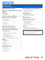 4
4
-
 5
5
-
 6
6
-
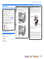 7
7
-
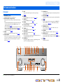 8
8
-
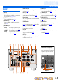 9
9
-
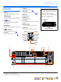 10
10
-
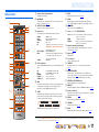 11
11
-
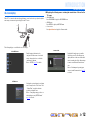 12
12
-
 13
13
-
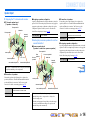 14
14
-
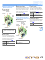 15
15
-
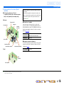 16
16
-
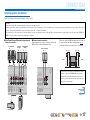 17
17
-
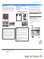 18
18
-
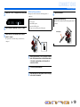 19
19
-
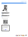 20
20
-
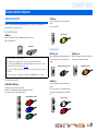 21
21
-
 22
22
-
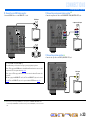 23
23
-
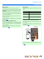 24
24
-
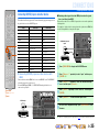 25
25
-
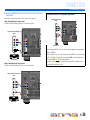 26
26
-
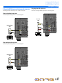 27
27
-
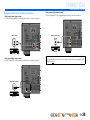 28
28
-
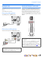 29
29
-
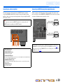 30
30
-
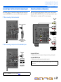 31
31
-
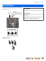 32
32
-
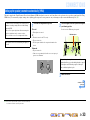 33
33
-
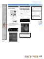 34
34
-
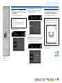 35
35
-
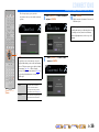 36
36
-
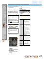 37
37
-
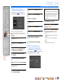 38
38
-
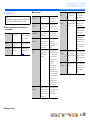 39
39
-
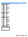 40
40
-
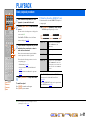 41
41
-
 42
42
-
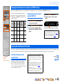 43
43
-
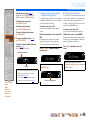 44
44
-
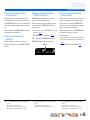 45
45
-
 46
46
-
 47
47
-
 48
48
-
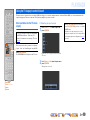 49
49
-
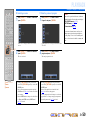 50
50
-
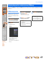 51
51
-
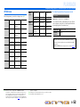 52
52
-
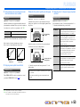 53
53
-
 54
54
-
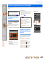 55
55
-
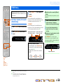 56
56
-
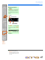 57
57
-
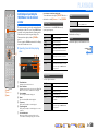 58
58
-
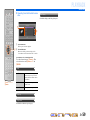 59
59
-
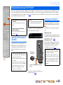 60
60
-
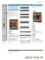 61
61
-
 62
62
-
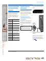 63
63
-
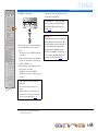 64
64
-
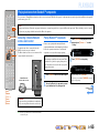 65
65
-
 66
66
-
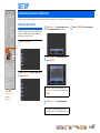 67
67
-
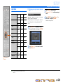 68
68
-
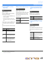 69
69
-
 70
70
-
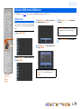 71
71
-
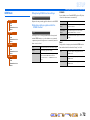 72
72
-
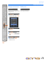 73
73
-
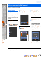 74
74
-
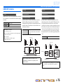 75
75
-
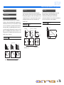 76
76
-
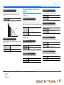 77
77
-
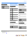 78
78
-
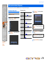 79
79
-
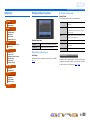 80
80
-
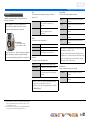 81
81
-
 82
82
-
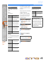 83
83
-
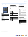 84
84
-
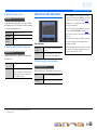 85
85
-
 86
86
-
 87
87
-
 88
88
-
 89
89
-
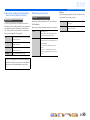 90
90
-
 91
91
-
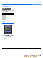 92
92
-
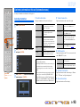 93
93
-
 94
94
-
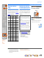 95
95
-
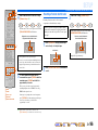 96
96
-
 97
97
-
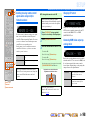 98
98
-
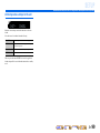 99
99
-
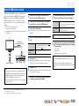 100
100
-
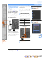 101
101
-
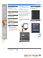 102
102
-
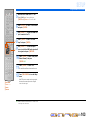 103
103
-
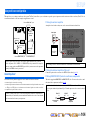 104
104
-
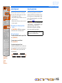 105
105
-
 106
106
-
 107
107
-
 108
108
-
 109
109
-
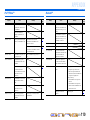 110
110
-
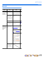 111
111
-
 112
112
-
 113
113
-
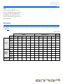 114
114
-
 115
115
-
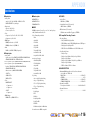 116
116
-
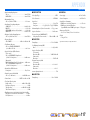 117
117
-
 118
118
-
 119
119
-
 120
120
-
 121
121
-
 122
122
-
 123
123
-
 124
124
-
 125
125
-
 126
126
-
 127
127
-
 128
128
-
 129
129


Yamaha RX-A800 El manual del propietario
- Categoría
- Receptores AV
- Tipo
- El manual del propietario
en otros idiomas
- français: Yamaha RX-A800 Le manuel du propriétaire
- italiano: Yamaha RX-A800 Manuale del proprietario
- English: Yamaha RX-A800 Owner's manual
- Deutsch: Yamaha RX-A800 Bedienungsanleitung
- русский: Yamaha RX-A800 Инструкция по применению
- Nederlands: Yamaha RX-A800 de handleiding
- português: Yamaha RX-A800 Manual do proprietário
- dansk: Yamaha RX-A800 Brugervejledning
- polski: Yamaha RX-A800 Instrukcja obsługi
- čeština: Yamaha RX-A800 Návod k obsluze
- svenska: Yamaha RX-A800 Bruksanvisning
- Türkçe: Yamaha RX-A800 El kitabı
- suomi: Yamaha RX-A800 Omistajan opas
- română: Yamaha RX-A800 Manualul proprietarului
Artículos relacionados
-
Yamaha RX-V767 El manual del propietario
-
Yamaha RX-V667 El manual del propietario
-
Yamaha RX-A800 El manual del propietario
-
Yamaha RX-V371 El manual del propietario
-
-
-
-
-
-