Peavey XR 696 Manual de usuario
- Categoría
- Amplificador de instrumentos musicales
- Tipo
- Manual de usuario

OPERATING GUIDE

2
Intended to alert the user to the presence of uninsulated “dangerous voltage” within the product’s
enclosure that may be of sufficient magnitude to constitute a risk of electric shock to persons.
Intended to alert the user of the presence of important operating and maintenance (servicing)
instructions in the literature accompanying the product.
CAUTION: Risk of electrical shock — DO NOT OPEN!
CAUTION: To reduce the risk of electric shock, do not remove cover. No user serviceable parts inside. Refer
servicing to qualified service personnel.
WARNING: To prevent electrical shock or fire hazard, do not expose this appliance to rain or moisture. Before
using this appliance, read the operating guide for further warnings.
Este símbolo tiene el propósito, de alertar al usuario de la presencia de “(voltaje) peligroso” que no tiene
aislamiento dentro de la caja del producto que puede tener una magnitud suficiente como para constituir
riesgo de corrientazo.
Este símbolo tiene el propósito de alertar al usario de la presencia de instruccones importantes sobre la
operación y mantenimiento en la literatura que viene con el producto.
PRECAUCION: Riesgo de corrientazo — No abra.
PRECAUCION: Para disminuír el riesgo de corrientazo, no abra la cubierta. No hay piezas adentro que el usario
pueda reparar. Deje todo mantenimiento a los técnicos calificados.
ADVERTENCIA: Para evitar corrientazos o peligro de incendio, no deje expuesto a la lluvia o humedad este
aparato Antes de usar este aparato, Iea más advertencias en la guía de operación.
Ce symbole est utilisé pur indiquer à l’utilisateur la présence à l’intérieur de ce produit de tension non-
isolée dangereuse pouvant être d’intensité suffisante pour constituer un risque de choc électrique.
Ce symbole est utilisé pour indiquer à l’utilisateur qu’il ou qu’elle trouvera d’importantes instructions sur
l’utilisation et l’entretien (service) de l’appareil dans la littérature accompagnant le produit.
ATTENTION: Risques de choc électrique — NE PAS OUVRIR!
ATTENTION: Afin de réduire le risque de choc électrique, ne pas enlever le couvercle. Il ne se trouve à l’intérieur
aucune pièce pouvant être reparée par l’utilisateur. Confier I’entretien à un personnel qualifié.
AVERTISSEMENT: Afin de prévenir les risques de décharge électrique ou de feu, n’exposez pas cet appareil à la
pluie ou à l’humidité. Avant d’utiliser cet appareil, lisez les avertissements supplémentaires situés dans le guide.
Dieses Symbol soll den Anwender vor unisolierten gefährlichen Spannungen innerhalb des Gehäuses
warnen, die von Ausreichender Stärke sind, um einen elektrischen Schlag verursachen zu können.
Dieses Symbol soll den Benutzer auf wichtige Instruktionen in der Bedienungsanleitung aufmerksam
machen, die Handhabung und Wartung des Produkts betreffen.
VORSICHT: Risiko — Elektrischer Schlag! Nicht öffnen!
VORSICHT: Um das Risiko eines elektrischen Schlages zu vermeiden, nicht die Abdeckung enfernen. Es befinden
sich keine Teile darin, die vom Anwender repariert werden könnten. Reparaturen nur von qualifiziertem
Fachpersonal durchführen lassen.
ACHTUNG: Um einen elektrischen Schlag oder Feuergefahr zu vermeiden, sollte dieses Gerät nicht dem Regen
oder Feuchtigkeit ausgesetzt werden. Vor Inbetriebnahme unbedingt die Bedienungsanleitung lesen.

XR
®
696 POWERED SOUND REINFORCEMENT MIXING CONSOLE
Representing years of research and development in mixer engineering, the XR 696 is a state-of-the-
art powered mixer packed with features. Incorporating DSP-based reverb/effects and delivering an
awesome output of 600 Watts per channel program material (@ 4 Ohms), this compact, lightweight
mixer is perfect for most any application. Designed for durability and ease of operation, the XR 696
will provide years of hassle-free performance.
FEATURES
• 8 low-noise, low-Z mic preamps
• 4 true high-Z 1/4" mic inputs
• 3-band equalization (Channels 1 - 8)
• Monitor send (each channel)
• EFX send (Channels 1 - 8)
• -25 dB pad (Channels 1 - 6)
• Low-cut filter (Channels 1 - 6)
• Stereo line inputs (Channels 7 - 9)
• 16-bit, DSP-based stereo reverb/effects with two parameter controls
• Two 9-band graphic EQs with FLS
®
Feedback Locating System
• 48 V phantom power
• Stereo/Main-Monitor mode switch
• 2x600 W @ 4 Ohms internal power amplifier
• DDT
™
speaker protection
The standard channels (1 - 8) feature discrete low noise mic preamps with globally switched
phantom power and 3-band EQ. Channels (1 - 4) feature true high-impedance 1/4" mic inputs. Two
additional channels (5 - 6) offer 1/4" line-level inputs. Channels (1 -6) feature globally switched Low
Cut filters. Channels (1 -6) feature Pad Switches to accomodate a wide range of input signals.
Finally, there are three stereo channels (7 - 9) for tape, CD, or synth inputs.
The Master section features a unique graphic equalizer/power amp mode switch. Without patching,
the XR 696 can be used as a full stereo mixer amplifier (default). In the Main/Monitor mode, one
graphic and amplifier can be used for monitor and the other graphic and amplifier for the main L and
R (mono) signal.
Also included in the Master section are 16 stereo digital effects from the award-winning Deltafex
®
digital signal processor. By including separate Time/Size and Color/Tone controls, the user can
create many effect settings from the 16 we provided. All channels, except Channel 9, have a
dedicated digital effects send routed directly to the DSP effects processor.
To take advantage of the XR 696’s powerful features, please read this owner’s manual carefully
and keep it as a reference. This manual includes several sections detailing individual areas of mixer
operation including: control functions, set-up, and applications in sound reinforcement.
3
ENGLISH

CHANNEL SECTION:
CHANNELS 1-4
1. MIC INPUT: XLR balanced, low-impedance channel input optimized for
a microphone or other low-level source. Pin 2 is the positive input.
Because of the wide range of gain adjustment, signal levels as high as
+10 dBV (2.45 V RMS) can be accommodated. When the phantom
power is enabled, this connector has +48 V on pins 2 and 3 with pin 1 as
the ground reference. (The Mic Input can also be found on Channels
5 - 8.) See caution on page 7.
2. HI-Z/LINE INPUT: Channels (1 -4) are 1/4" balanced TRS high-
impedance inputs. The tip is the positive input, which can also be used for
unbalanced inputs. A Pad (#3) switch is provided to attenuate strong
signals present at this input. Within the same channel, the mic input and
the Hi-Z/Line input cannot be used simultaneously.
3. PAD: Attenuates the input signal by 25 dB. If you find that barely
touching the Level control (#4) gives you an enormous increase in
volume or if distortion occurs, try using the Pad switch. In addition to
increasing the dynamic range, the channel input can now accommodate
a higher input level before clipping. This may be necessary with a close
mic on loud guitar amplifiers or drum kits. The Pad switch can also be
found on Channels 5 and 6 which are line level inputs only.
4. GAIN: Sets the signal level sent to the Left and Right bus. (The Gain
control can also be found on Channels 5 - 9.)
5. MON: Adjusts the level of the channel signal (pre-EQ) that is added to
the Monitor mix. (The Monitor control can also be found on Channels
5 - 9.) This control is independent of the main channel Gain control (#4).
6. LOW EQ: A shelving type of active tone control that varies the bass
frequency levels ±15 dB at 70 Hz. It will add depth to thin signals, or
clean up muddy ones. (The Low control can also be found on Channels
5 - 9.)
7. MID EQ: Mid ±15 dB. This control sets the amount of cut and boost at
the mid-frequency. (The Mid control can also be found on Channels
5 - 8.)
8. HIGH EQ: A shelving type of active tone control that varies the treble
frequency levels ±15 dB at 12 kHz. It is designed to remove noise or to
add brilliance to the signal, depending on the quality of the source. (The
High control can also be found on Channels 5 - 9.)
9. EFX: This control varies the level into the digital effects processor bus
adjusting the signal level from the particular channel to the digital
processor. (The effects control can also be found on Channels 5 - 8.)
The channel Gain control (#4) also affects this level.
4
5
0
10
MON
+15
LOW
0
-15
+15
0
-15
MID
HIGH
+15
0
-15
5
0
10
EFX.
1
PAD
1
-25dB
HI Z/
LINE
MIC
HI Z/
LINE
MIC
5
0
10
MON
-15
0
+15
0
-15
MID
5
0
10
EFX.
-3
0dB
+3
+6
-6
+20 GAI
N
-3
0dB
+3
+6
-6
+20 GAI
N
1
4
5
6
7
8
9
2
3

NOTE: Channels 5-9 contain features that differ from the previous
channels. Only those features are mentioned below. For information on
features not mentioned please refer to the section for Channels 1-4.
CHANNELS 5-6
10. LINE: 1/4" balanced TRS input for line-level signals. This signal is
connected through a 25 dB pad to the mic input below it.
11. LOW CUT: This is a low-cut filter with a corner frequency of 80 Hz used
to filter rumble, wind noise, breath thumps, stage noise, and other low-
frequency components that rob power from the amplifiers and muddy the
signal. Depressing this switch will affect Channels 1 - 6 only. Use of the
filter will not affect the monitor signal.
CHANNELS 7-8
12. RIGHT INPUT: High-impedance 1/4" input for line-level signals. The Right
Input is adjusted by the Level control (#4). If the XR
®
696 is in Left/Right
mode then the signal will go to the Right Speaker Output (#37). In
Mon/Main mode the signal is combined with the Left and placed on the
Main Speaker Output. The right signal can also be patched out of the XR
696 via the Right Output jack (#31) to external components such as
effects, power amps, and recording devices.
13. LEFT/MONO INPUT: High-impedance 1/4" input for line-level signals. The
Left/Mono input supplies signal to both the Left and Right channels (if
there is nothing inserted to the right input jack) through the Level control
(#4). In Left/Right mode the signal will go to the Left Speaker Output (and
Right Speaker Output if nothing is inserted to the right input jack). In
Mon/Main mode the signal is combined with the Right and placed on the
Main Speaker Output.
CHANNEL 9
14. TAPE IN: This stereo RCA phono jack accepts a stereo input (nominally
-10 dBV) from the output of a tape deck or CD player and places it on the
Left and Right channels as well as the monitor mix.
15. TAPE OUT: This stereo RCA phono jack provides a signal for the
recording inputs of a stereo tape deck.
CAUTION: DO NOT HOOK THE TAPE IN AND TAPE OUT TO THE
INPUT AND OUTPUT OF THE SAME DECK. DOING SO WILL FORM A
LOOP CAUSING SEVERE FEEDBACK. USE SEPARATE DECKS FOR
RECORDING AND PLAYBACK.
5
PAD
6
7
-25dB
LEFT/
MONO
LINE
LINE
RIGHT
MIC MIC
LINE
55
0
10
MON
0
10
MON
0
+15
LOW
0
+15
LOW
-15 -15
+15
0
-15
MID
+15
0
-15
MID
HIGH
+15
0
-15
HIGH
+15
0
-15
5
0
10
EFX.
5
0
10
EFX.
6
low
cut
7
STEREO
-3
0dB
+3
+6
-
6
+20 GAIN
-3
0dB
+3
+6
-6
+20 GAI
N
13
11
12
10
LEFT
RIGHT
REC OUT
LEFT
RIGHT
LINE IN
14
15

6
MASTER SECTION
16. EFFECTS PEAK LED: Illuminates to indicate -6 dB of headroom before the signals being sent to the
effects circuit are clipped. Ideally, you would want this LED to light only occassionally. An occassional
blink indicates that you have the levels at an optimum setting. It is advisable to listen carefully to the
output at the same time in order to determine the final setting.
17. PRESET: Selects the effect preset from the list below.
EFX Presets
PRESET NAME TIME/SIZE COLOR/TONE
1 Chamber Time: 150 to 5,000 ms Damping (High Frequency)
2 Plate Time: 100 to 4,000 ms Damping (High Frequency)
3 Room Time: 150 to 5,000 ms Damping (High Frequency)
4 Cathedral Time: 100 to 8,000 ms Damping (High Frequency)
5 Spring Time: 150 to 5,000 ms Damping (High Frequency)
6 Gate Time: 150 to 500 ms Damping (High Frequency)
7 Reverse Time: 150 to 500 ms Damping (High Frequency)
8 Delay + Reverb Time: 0 to 225 ms Reverb Time: 0 to 5,000 ms
9 Bright Delay Time: 0 to 500 ms Feedback: 0 to 99%
10 Warm Delay Time: 0 to 500 ms Feedback: 0 to 99%
11 Dark Delay Time: 0 to 500 ms Feedback: 0 to 99%
12 Ping Pong Delay Time: 0 to 500 ms Feedback: 0 to 99%
13 Chorus Rate: 0.125 to 8 Hz Depth: Best Set Full CW
14 Phaser Rate: 0.250 to 16 Hz Depth: Best Set Full CW
15 Flange Rate: 0.10 to 2.5 Hz Depth: Best Set Full CW
16 Rotary Speaker High Speed: 0.50 to 25 Hz Width: 0 to 100% CW
18. TIME/SIZE: In Reverb and Delay presets, this control adjusts the time of the particular reverb or
delay; in Chorus, Phaser, and Flange, it adjusts the rate of each. In Rotary Speaker setting, this
adjusts the speed of the speaker rotation.
19. COLOR/TONE: Adjusts the high-frequency content of the effects signal. (While using a delay, this
control adjusts the feedback or depth.)
20. EFX TO MON: Controls the amount of effects signal sent to the monitor mix. This control allows
effects to be heard from the stage via the monitor.
21. EFX TO MAIN: Controls the amount of effects signal sent to the main mix.
22. FLS
®
(Feedback Locator System): These LEDs illuminate to indicate the frequency band of highest
energy. When feedback occurs, this system will automatically indicate the graphics slider to use to
decrease that frequency band’s gain in order to lessen or eliminate feedback. (NOTE: These LEDs
illuminate with any audio signal, not just during feedback.)
23. GRAPHIC EQUALIZERS: These 9-band equalizers are fixed on one-octave centers. They are
designed for 12 dB of cut and 12 dB boost. They are connected directly to their power amplifier inputs.
24. SYSTEM MODE: This switch is used to configure the XR
®
696 as either a stereo or dual mono
amplifier. It is recessed to prevent accidental switching during a performance. Use a non-metallic
object to change the switch position (e.g., a toothpick). The XR 696 is shipped from the factory in the
default setting of Left Main to the upper EQ and Right to the lower EQ. When this switch is depressed,
it switches the lower EQ to (mono) PA Left + Right. The upper EQ then becomes the monitor signal
only, creating an entire PA and monitor mixing system in one small, easy-to-carry package. And this
change is accomplished without a single patch cord!

25. MONITOR LEVEL: Sets the overall level of the monitor signal that is sent to the Monitor Output Jack.
This control also sets the monitor level going to the power amp when in Main/Monitor mode (see
System Mode #24).
26. MAIN LEVEL: This is the master level control for the main mix sent to the Left/Mono and Right
output jacks. This control sets the Main level going to the power amp when in Main/Monitor mode (see
System Mode #24). A good starting position for this control is the center detent position (12:00).
27. PHANTOM POWER SWITCH: Applies 48 V DC voltage to all input XLR connectors to power
microphones that require it.
CAUTION! When phantom power is switched on, make sure that any channel you are plugging a mic
into is turned down in both the main and monitor mixes. Otherwise, there will be a loud pop in the PA.
This is normal. It is best to plug all mics into their respective channels with the phantom power
switched off. This reduces noise in the PA and reduces the chances of the mic being damaged. If
phantom power is used, do not connect unbalanced microphones or other devices that cannot handle
this voltage to the XLR inputs. (Some wireless receivers may be damaged; consult their manuals for
compatibility.) The line input 1/4" jacks are not connected to the phantom supply, and are safe for all
inputs (balanced or unbalanced). An unbalanced-to-balanced impedance converter, such as the
Peavey 5116 or a Peavey 1:1 Interface Adapter, can also be used to isolate a mic from phantom
voltage.
7
-
12
-
12
+
12
+
12
MONITOR
0dB
-
3
3
+
-
6
+
6
10
+
GAIN
GAIN
0dB
-
3
3
+
-
6
+
6
10
+
MAIN
MODE
E
Q
/
P
W
R
A
MP
SELE
C
STEREO
MAIN
MON/
XR
696
1
200W
2X600w
STEREO
POWER
MIXER
-
12
-
12
+
12
+
12
/
DESIGNED IN U.S.A.
BUILT UNDER U.S. PATENT
NO.
5,737,428
/
4,318,053
ON
48V
PHANTOM
EFX.
DEFEAT
MONITOR
LEFT/MONO
RIGHT
LEFT
RIGHT
POWER
AMP
IN
LINE
OUTPUT
FT.
SW.
GAIN
E
SET
S
PEAK
(-6dB)
63
125
250
500
1K
2K
4K
8K
16K
63
125
250
500
1K
2K
4K
8K
16K
LEFT
/
MONITOR
EQUALIZATION
PRESET
TIME
/
SIZE
COLOR
/
TONE
EFX.
TO
MON.
EFX.
TO
MAIN
SENDS
POWER
FLS
FEEDBACK
LOCATING
SYSTEM
11
1
1
1
5
5
3
3
7
9
5
1
0
0
5
1
0
0
1
0
0
5
1
0
0
5
RIGHT
MAIN
EQUALIZATION
DIGITAL
EFFECTS
33
25
21
24
22
23
32
26
31
22
16
23
30292827
20
191817

28. EFX DEFEAT: This 1/4" jack accepts an on/off 1/4" footswitch (Peavey Pt. #00051000) to defeat the
effects of both the Main and Monitor mixes.
29. MONITOR OUTPUT: This 1/4" jack provides an output from the monitor mix to supply external power
amp/monitor combinations. The level of this signal is determined by the Monitor Level control.
30. LEFT/MONO OUTPUT: This 1/4" jack provides an output from the Left Main mix to supply external
amp/speaker combinations. The level of this signal is determined by the Main Level control. When no
plug is connected to the Right Output (#31) then the right signal is mixed with the left, and both can
be accessed at the Left/Mono Output. This works well when you use the internal amps for monitor and
external amps for Main. Only one patch cord is required to get the Main out to the external amp. In
order to utilize both internal amps for Monitors then patch from Monitor Out into Right Power input.
31. RIGHT OUTPUT: This 1/4" jack provides an output from the Right Main mix to supply external
amp/speaker combinations. The level of this signal is determined by the Main Level control.
32. POWER AMP INPUTS: Plugging into these jacks allows the user to go directly into the graphic
equalizer, then into its respective power amplifier channel, and therefore bypass the other functions of
the XR
®
696.
33. POWER LED: The power “on” LED indicator will light when the unit is powered.
AC POWER AND POWER AMPLIFIER SECTION:
34. A/C POWER INLET: This is the receptacle for an IEC line cord,
which provides AC power to the mixer/amplifier. Connect the line
cord to this connector to provide power to the unit. Damage to
the equipment may result if improper line voltage is used (see
line voltage marking on unit).
35. POWER: The XR 696’s main power switch. The power on LED
indicator (#33) will light when the unit is powered.
36. FUSE: This is the main safety fuse for the AC line voltage. Only
replace the fuse with one the exact same type and rating. IF THE FUSE CONTINUES TO OPEN, DO
NOT OVER FUSE. TAKE THE UNIT TO AN AUTHORIZED PEAVEY SERVICE CENTER!
37. PARALLEL LEFT/RIGHT SPEAKER OUTPUTS: These 1/4" jacks are the amplifier’s outputs. By
connecting a speaker cable to this jack and to a speaker cabinet, you complete the signal chain.
You will notice that there are two pairs of jacks. The two pairs are your two (stereo) amp outputs.
Two cabinets can be connected to each channel, as long as the combined impedance of the cabinets
is not less than 4 Ohms. (i.e., two 8 Ohm cabinets in parallel = 4 Ohms, four 16 Ohm speakers in
parallel = 4 Ohms, etc.).
8
POWER
500 WATTS
60 Hz
120 VAC
OFF
ON
FUSE
15 AMP
34 36
35
37
CLASS 2 WIRING
RIGHT/MAIN
4
MIN
OHM
LEFT/ MONITOR
4
MIN
OHM

9
CHANNELS 1-4
HI-Z INPUT
MIC PREAMP
PAD
TONE CONTROL
LO MIDHI
+48V Phantom
LO-Z INPUT
CHANNELS 5-6
LINE INPUT
MIC PREAMP
+48V Phantom
LO-Z INPUT
MONITOR SEND
CHANNEL GAIN
EFX LEVEL
TONE CONTROL
CHANNEL GAIN
EFX LEVEL
MONITOR SEND
CHANNELS 7-8
STEREO LINE INPUT
LEFT/
MONO
RIGHT
+48V Phantom
LO-Z INPUT
MIC PREAMP
CHANNEL 9 (TAPE)
TAPE/CD
INPUT
TONE CONTROL
LO HI
CHANNEL GAIN
LO HI
LO MID HI
TONE CONTROL
LO MID HI
CHANNEL GAIN
LO MID HI
Monitor Send
Low Cut
(80 Hz)
Monitor
Master
Monitor Output
Right Main Output
Right Power Amp Input
Right/Main
Power Amp
Power Amp
DDT
Left/Monitor
Power Amp Out
Bridge Out
Left/Monitor
Power Amp Out
DDT
Left/Monitor
Left Power Amp Input
Mode Select
Left/Mono Main Output
Tape Out
Effects to
Monitor
Effects
Selector
Peak
LED
Time
Color
Effects to Main
Stereo
Digital
Effects
Effect Defeat
210 WATTS PER CHANNEL • 4 OHMS
150 WATTS PER CHANNEL • 8 OHMS
BRIDGE 420 WATTS • 8 OHMS
Mon Send
EFX LEVEL
1-6 BUS
MON BUS
EFX BUS
LEFT BUS
RIGHT BUS
PAD
XR
®
696 BLOCK DIAGRAM
600 WATTS PER CHANNEL (PROGRAM) • 4 OHMS
475 WATTS PER CHANNEL (PROGRAM) • 8 OHMS
Right/Main
Power Amp Out

XR
®
696 LEVEL DIAGRAM
10
INPUTS
HI-Z
(W/PAD)
LINE/TAPE
LO-Z MIC
(W/PAD)
LO-Z MIC
(NO PAD)
HI-Z MIC
(NO PAD)
-60
-50
-40
-30
-20
-10
0 dBu
+10
+20
+30
+21 dBu
+13.5 dBu
-11 dBu
-12.5 dBu
-28 dBu
-35 dBu
-60 dBu
+2 dBu = 0 dBV
-15 dB
+15 dB
EQ
MONITOR OUT
+21 dBu MAX
TAPE OUT
+10 dBu MAX
-10 dBu NOM.
LEFT & RIGHT OUT
+21 dBu MAX
GRAPHIC EQ
+12 dB
-12 dB
TO POWER AMPS
+ 2 dBu NOMINAL

11
Left/Monitor Outputs (Rear)
Right/Main Outputs (Rear)
Impulse
®
1012
Impulse
®
1012
Mains - Left Mains - Right
Mode
Switch
Out
Keyboard
PVM
™
22
Reactor
™
-
12
-
12
+
12
+
12
MONITOR
0dB
-
3
3
+
-
6
+
6
10
+
GAIN
GAIN
0dB
-
3
3
+
-
6
+
6
10
+
MAIN
MODE
E
Q
/
P
W
R
A
MP
SELECT
STEREO
MAIN
MON/
XR
696
1
200W
2X600w
STEREO
POWER
MIXER
-
12
-
12
+
12
+
12
/
DESIGNED IN U.S.A.
BUILT UNDER U.S. PATENT
NO.
5,737,428
/
4,318,053
ON
48V
PHANTOM
EFX.
DEFEAT
MONITOR
LEFT/MONO
RIGHT
LEFT
RIGHT
POWER
AMP
IN
LINE
OUTPUT
FT.
SW.
GAIN
-3
0dB
+3
+6
-6
+20 GAIN
5
0
10
MON
+15
LOW
0
-15
+15
0
-15
MID
HIGH
+15
0
-15
5
0
10
EFX.
1
PAD PAD PAD PAD PAD PAD
1
2
3
5
6
7
8
9
-25dB -25dB -25dB -25dB -25dB -25dB
LEFT/
MONO
LEFT/
MONO
LINE LINE
HI Z/
LINE
HI Z/
LINE
HI Z/
LINE
HI Z/
LINE
LINE LINE
RIGHT RIGHT
MIC MIC MIC MIC MIC MIC MIC MIC
LEFT
RIGHT
REC OUT
LEFT
RIGHT
LINE IN
LINE
PAD
4
-25dB
HI Z/
LINE
MIC
-3
0dB
+3
+6
-6
+20 GAIN
-3
0dB
+3
+6
-6
+20 GAIN
5
0
10
MON
-15
-3
0dB
+3
+6
-6
+20 GAIN
-3
0dB
+3
+6
-6
+20 GAIN
-3
0dB
+3
+6
-6
+20 GAIN
-3
0dB
+3
+6
-6
+20 GAIN
-3
0dB
+3
+6
-6
+20 GAIN
-3
0dB
+3
+6
-6
+20 GAIN
-3
0dB
+3
+6
-6
+20 GAIN
0
10
MON
+15
LOW
-15
55555555
0
10
MON
0
10
MON
0
10
MON
0
10
MON
0
10
MON
0
10
MON
0
10
MON
000
+15
LOW
0
+15
LOW
0
+15
LOW
0
+15
LOW
0
+15
LOW
-15 -15 -15 -15 -15 -15
0
+15
LOW
+15
0
-15
MID
+15
0
-15
MID
+15
0
-15
MID
+15
0
-15
MID
+15
0
-15
MID
+15
0
-15
MID
+15
0
-15
MID
+15
0
-15
MID
+15 +15
+15
LOW
-15
0
HIGH
+15
0
-15
5
0
10
EFX.
8
STEREO
+15
-15
0
HIGH
STEREO
9
PRESET
1
-
7
REVERBS
8
DELAY
+
REVERB
9
-
12
DELAYS
13
-
1
5
MODULATIONS
1
6
ROTARY
SPEAKER
PEAK
(-6dB)
HIGH
+15
0
-15
HIGH
+15
0
-15
HIGH
+15
0
-15
5
0
10
EFX.
5
0
10
EFX.
5
0
10
EFX.
5
6
low
cut
7
STEREO
HIGH
0
-15
HIGH
0
-15
HIGH
+15
0
-15
5
0
10
EFX.
5
0
10
EFX.
5
0
10
EFX.
2
3
4
5
0
10
EFX.
LOW CUT
80Hz CHANNELS 1-6 ONLY
63
125
250
500
1K
2K
4K
8K
16K
63
125
250
500
1K
2K
4K
8K
16K
LEFT
/
MONITOR
EQUALIZATION
PRESET
TIME
/
SIZE
COLOR
/
TONE
DIGITAL
EFFECTS
EFX.
TO
MON.
EFX.
TO
MAIN
SENDS
POWER
FLS
FEEDBACK
LOCATING
SYSTEM
11
1
1
1
5
5
3
3
7
9
5
1
0
0
5
1
0
0
1
0
0
5
1
0
0
5
RIGHT
MAIN
EQUALIZATION
MAQ
™
150
SP
™
112MX
Out
Tape Player
Tape Player In
Stereo Voice Module
L
R
Wireless
Mic/Gtr
Hi Z Mic
XR
®
696 In - Left/Right Mode

12
Left/Monitor Outputs (Rear)
Right/Main Outputs (Rear)
Impulse
®
1012
Monitors
Mains
Mode
Switch
Depressed
(In)
PVM
™
22
Reactor
™
Keyboard
-
12
-
12
+
12
+
12
MONITOR
0dB
-
3
3
+
-
6
+
6
10
+
GAIN
GAIN
0dB
-
3
3
+
-
6
+
6
10
+
MAIN
MODE
E
Q
/
P
W
R
A
MP
SELECT
STEREO
MAIN
MON/
XR
696
1
200W
2X600w
STEREO
POWER
MIXER
-
12
-
12
+
12
+
12
/
DESIGNED IN U.S.A.
BUILT UNDER U.S. PATENT
NO.
5,737,428
/
4,318,053
ON
48V
PHANTOM
EFX.
DEFEAT
MONITOR
LEFT/MONO
RIGHT
LEFT
RIGHT
POWER
AMP
IN
LINE
OUTPUT
FT.
SW.
GAIN
-3
0dB
+3
+6
-6
+20 GAIN
5
0
10
MON
+15
LOW
0
-15
+15
0
-15
MID
HIGH
+15
0
-15
5
0
10
EFX.
1
PAD PAD PAD PAD PAD PAD
1
2
3
5
6
7
8
9
-25dB -25dB -25dB -25dB -25dB -25dB
LEFT/
MONO
LEFT/
MONO
LINE LINE
HI Z/
LINE
HI Z/
LINE
HI Z/
LINE
HI Z/
LINE
LINE LINE
RIGHT RIGHT
MIC MIC MIC MIC MIC MIC MIC MIC
LEFT
RIGHT
REC OUT
LEFT
RIGHT
LINE IN
LINE
PAD
4
-25dB
HI Z/
LINE
MIC
-3
0dB
+3
+6
-6
+20 GAIN
-3
0dB
+3
+6
-6
+20 GAIN
5
0
10
MON
-15
-3
0dB
+3
+6
-6
+20 GAIN
-3
0dB
+3
+6
-6
+20 GAIN
-3
0dB
+3
+6
-6
+20 GAIN
-3
0dB
+3
+6
-6
+20 GAIN
-3
0dB
+3
+6
-6
+20 GAIN
-3
0dB
+3
+6
-6
+20 GAIN
-3
0dB
+3
+6
-6
+20 GAIN
0
10
MON
+15
LOW
-15
55555555
0
10
MON
0
10
MON
0
10
MON
0
10
MON
0
10
MON
0
10
MON
0
10
MON
000
+15
LOW
0
+15
LOW
0
+15
LOW
0
+15
LOW
0
+15
LOW
-15 -15 -15 -15 -15 -15
0
+15
LOW
+15
0
-15
MID
+15
0
-15
MID
+15
0
-15
MID
+15
0
-15
MID
+15
0
-15
MID
+15
0
-15
MID
+15
0
-15
MID
+15
0
-15
MID
+15 +15
+15
LOW
-15
0
HIGH
+15
0
-15
5
0
10
EFX.
8
STEREO
+15
-15
0
HIGH
STEREO
9
PRESET
1
-
7
REVERBS
8
DELAY
+
REVERB
9
-
12
DELAYS
13
-
1
5
MODULATIONS
1
6
ROTARY
SPEAKER
PEAK
(-6dB)
HIGH
+15
0
-15
HIGH
+15
0
-15
HIGH
+15
0
-15
5
0
10
EFX.
5
0
10
EFX.
5
0
10
EFX.
5
6
low
cut
7
STEREO
HIGH
0
-15
HIGH
0
-15
HIGH
+15
0
-15
5
0
10
EFX.
5
0
10
EFX.
5
0
10
EFX.
2
3
4
5
0
10
EFX.
LOW CUT
80Hz CHANNELS 1-6 ONLY
63
125
250
500
1K
2K
4K
8K
16K
63
125
250
500
1K
2K
4K
8K
16K
LEFT
/
MONITOR
EQUALIZATION
PRESET
TIME
/
SIZE
COLOR
/
TONE
DIGITAL
EFFECTS
EFX.
TO
MON.
EFX.
TO
MAIN
SENDS
POWER
FLS
FEEDBACK
LOCATING
SYSTEM
11
1
1
1
5
5
3
3
7
9
5
1
0
0
5
1
0
0
1
0
0
5
1
0
0
5
RIGHT
MAIN
EQUALIZATION
Out
Tape Player
Tape Player In
Stereo Voice Module
L
R
Wireless
Mic/Gtr
Hi Z Mic
SP
™
112MX
XR
®
696 In Monitor/Main Mode

13
XR
®
696
SPECIFICATIONS
:
Input Specifications:
Function Input Z Input Gains Input Levels Bal/ Connector
(Ohms) Control Min** Nominal* Max Unbal.
Min Setting
Lo-Z 2 k Max w/o pad -60 dBu -30 dBu -11 dBu Bal. XLR: Pin 1 Gnd,
(150 Ohms) (50 dB) Pin 2 (+), Pin 3 (-)
Channels 1-8 Max. w/ pad -35 dBu -5 dBu +13.5 dBu
(25 dB)
Hi-Z 100 k Max w/o pad -60 dBu -30 dBu -12 dBu Bal. 1/4" TRS: Tip (+),
(50 dB) Ring (-),
Sleeve Ground
Channels 1-4 Max w/ pad -35 dBu -5 dBu +12.5 dBu
(25 dB)
Line Input 22 k Max. w/o pad -28 dBu +2 dBu +21 dBu Unbal. 1/4" TRS: Tip (+),
(30 dB) Ring (-),
Channels 5-8 Max. w/ pad -3 dBu +27 dBu +46 dBu Sleeve Ground
(5 dB)
Tape 20 k Max. Gain -28 dBu +2 dBu +21 dBu Unbal. RCA Jacks
Channel 9 (30 dB)
0 dBV=1V (RMS) open load or 0 dBVu = .775 V (RMS)
** Min input level (sensitivity) is the smallest signal that will produce nominal output (2 dBu) with channel and master
level controls set for maximum gain.
* Nominal settings are defined as all controls set a 0 dB (or 50% rotation for rotary pots)
XR 696 Output Specifications:
Function Minimum Load Z Output Level Bal./Unbal. Connector
(Ohms)
Nominal Max.
Main L/R 600 +2 dBu +21 dbu Unbal. 1/4" Phono Tip (+),
Sleeve Ground
Monitor 600 +2 dBu +21 dBu Unbal. 1/4" Phono Tip (+),
Sleeve Ground
Tape 10 k -10 dBu +10 dBu Unbal. RCA
+2 dBu = 0 dBV = 1V (RMS)
Gain:
Mic Input to L and R Output
Hi-Z Input to L and R Output
Line Input to L and R Output
60 dB (Max. Gain)
60 dB (Max. Gain)
30 dB (Max. Gain)

Frequency Response:
Mic Input to L - R Output
Line Input to L - R Output
To Power Amplifier Output
20 Hz - 20 kHz +0 dB/-1 dB
20 Hz - 20 kHz +0 dB/-1 dB
20 Hz - 20 kHz +0 dB/-1 dB
14
Graphic Equalizer:
Filter Bandwidth
Filter Frequencies
Maximum Boost and Cut
1 octave
63, 125, 250, 500, 1 k, 2 k, 4 k, 8 k, 16 k
+12 dB Boost, -12 dB Cut
Total Harmonic Distortion (THD):
< 0.01% 20 Hz - 20 kHz mic input to L/R Mon. output at nominal level (20 Hz - 80 kHz BW)
< 0.01% 20 Hz - 20 kHz line input to L/R output at output at nominal level (20 Hz - 80 kHz BW)
< .005% Typical at 1 kHz
XR
®
696 Hum and Noise:
Output Residual Noise S/N Ratio Test Conditions
Ref: 0 dBu Ref: 2 dBu
Main Left -98 dBu -100 dB All controls down
and Right
-89 dBu -91 dB One channel nominal, master
nominal
-81 dBu -83 dB Master level nominal,
Channel level nominal, Mic
inputs terminated @ 150 Ohms
Monitor -96 dBu -98 dB All controls down
-90 dBu -92 dB One channel nominal, master
nominal
-81 dBu -83 dB Master level nominal,
Channel level nominal, Mic
inputs terminated @ 150 Ohms
(Hum and noise measurements: 22 Hz to 22 kHz BW)
S/N Ratio:
> 85 dB below rated output (500 W/channel), mic/line to speaker output
Equivalent Input Noise (EIN):
-121.5 dBu (Input terminated with 150 Ohms)
Crosstalk:
> 80 dB adjacent input channels (20 Hz - 20 kHz)
> 70 dB left to right outputs (20 Hz - 20 kHz)
Common Mode Rejection Ratio (Mic Input):
50 dB min. (20 Hz - 20 kHz)
60 dB typical @ 1 kHz

15
POWER SECTION
(1200 SC Module with DDT
™
)
Frequency Response:
+0, -1 dB, 20 Hz - 20 kHz @ rated power
Rated Power:
• 600 Watts program into 4 Ohms, both
channels driven / 500 Watts RMS into 4 Ohms,
both channels driven
• 475 Watts program into 8 Ohms, both
channels driven / 360 Watts RMS into 8 Ohms,
both channels driven
Total Harmonic Distortion:
Less than 0.1% @ 1 kHz @ rated power
DDT Dynamic Range:
Greater than 26 dB
DDT Maximum Distortion:
Below 0.5% THD for 6 dB overload
Below 1% THD for 20 dB overload
Hum and Noise:
-97 dB below 500 Watts
Damping Factor:
Greater than 100 @ 1 kHz, 4 Ohms
Input Sensitivity:
2.2 V RMS for 500 Watts @ 4 Ohms
Input Impedance:
2 k Ohms
Power Requirements:
500 Watts, 120 V AC, 60 Hz, Nominal
Dimensions:
Width: 19.0"
Height: 10.75"
Depth: 11.0"
Weight: 41.9 lbs.
XR
®
696/1200 SC AMPLIFIER SPECIFICATIONS

CONSOLA DE MEZCLA PARA REPRODUCCIÓN
DE SONIDO CON PODER XR
®
696
Representando años de construcción e investigación en ingeniería de consolas, la XR 696 es una
consola con poder del más alto nivel. Incorporando procesadores de reverberación y otros efectos
basados en DSP (Proceso de señal digital, por sus siglas en inglés) y sorprendente salida de 600
watts por canal (@ 4 ohmios), esta consola compacta y de bajo peso es perfecta para casi
cualquier aplicación. Diseñada pensando en durabilidad y facilidad de uso, la XR 696 brindará años
de uso libre de problemas.
CARACTERÍSTICAS
• 8 preamplificadores de bajo ruido, Low-Z para micrófonos
• 4 entradas de Micrófono de high-Z de 1/4"
• Ecualización de 3 bandas (canales 1-8)
• Envío de monitor (cada canal)
• Envío de efectos (canales 1-8)
• Pad de –25 dB (canales 1-6)
• Filtro de recorte de graves (canales 1-6)
• Entradas de línea estéreo (canales 7-9)
• Efectos/Reverberación DSP de 16 bits con dos parámetros de control.
• Dos ecualizadores de 9 bandas con FLS (Sistema de localización de retroalimentación, por sus
siglas en inglés)
• Poder phantom de 48 V
• Interruptor seleccionador de modo Estéreo/Monitor Main
• Amplificador de poder interno de 2 x 600 W @ 4 ohmios
• Protección de parlantes DDT
™
Los canales estándar (1-8) incluyen preamplificadores de micro discretos de bajo ruido con poder
phantom global y ecualizador de 3 bandas. Los canales 1-4 incluyen entradas de micro de
verdadera impedancia alta de 1/4". Dos canales adicionales (5-6) ofrecen entradas de nivel de 1/4".
Los canales 1–6 incluyen pads para poder incorporar filtros de graves globales. Finalmente, hay
tres canales estéreo (7-9) para cintas, CDs o entradas de sintetizadores.
La sección maestra ofrece un interruptor para seleccionar entre los modos ecualizador
gráfico/amplificador de poder. Sin parchar, la XR 696 puede ser usada como una
consola/amplificador (posición de fábrica). En el modo Main/Monitor, un eq gráfico y un amplificador
pueden ser usados para el monitor y el otro gráfico/amplificador para la señal de salida principal
(main) L & R (mono).
También incluidos en la sección maestra hay 16 efectos digitales estéreo del reconocido procesador
digital Deltaflex
®
. Al incluir controles separados de tiempo/tamaño y color/tono, el operador puede
crear variados efectos de los 16 incluidos. Todos los canales, excepto el canal 9, tienen envíos
dedicados ruteados directamente al procesador de efectos DSP.
Para aprovechar todas las posibilidades de la XR 696, por favor lea este manual cuidadosamente y
manténgalo a la mano para referencia en el futuro. Este manual incluye varias secciones detallando
las áreas individuales de la operación de la consola incluyendo: controles, instalación y aplicaciones
de uso.
16
ESPAÑOL

SECCIÓN DE CANALES
CANALES 1-4
1. ENTRADA DE MICRÓFONO: Entrada de baja impedancia, XLR,
balanceada optimizada para micrófonos u otra fuentes de bajo
nivel. La aguja 2 es la entrada positiva. Dado el amplio rango de
ajustes de ganancia, se pueden usar señales de hasta +10 dBV
(2.45 V RMS). Cuando el poder phantom es encendido, este
conectador llevara +48 V en las agujas 2 y 3 con la aguja 1 siendo
la tierra. (La Entrada de Micro también se puede encontrar en los
canales 5-8) Ver precauciones en la página 7.
2. ENTRADA DE LÍNEA/HI-Z: Las entradas de los canales 1-4 son
TRS balanceadas de 1/4" de alta impedancia. La punta es la
entrada positiva, que también puede ser usada para entradas no
balanceadas. Un interruptor de pad (3) se incluye para disminuir
señales elevadas en esta entrada. En un mismo canal no se
pueden usar las entradas de micrófono y línea simultáneamente.
3. PAD: Disminuye la señal de entrada por 25 dB. Si el resultado de
elevar un poco en control de ganancia (4) tiene como resultado un
fuerte incremento en nivel o distorsión, se debe usar el pad.
Además de incrementar el rango dinámico, el canal ahora podrá
procesar una entrada más elevada antes de saturar. Esto puede
ser necesario con un micro de batería o uno en un amplificador de
guitarra. El interruptor de pad también se puede encontrar en los
canales 5 y 6 que son sólo para entradas de línea.
4. GANANCIA: Ajusta el nivel de señal que se envía al bus L/R.
(El control de ganancia también puede ser encontrado en los
canales 5-9)
5. MON: Ajusta el nivel de la señal (pre EQ) que se añade a la
mezcla del monitor. (El control del monitor también se puede
encontrar en los canales 5-9). Este control es independiente del
control de ganancia del canal (4).
6. EQ GRAVE: Un controlador de tono tipo ‘shelving’ varía las
frecuencias graves por ± 15 dB en 70 Hz. Añadirá profundidad a
señales delgadas y limpiará las lodosas (este control de graves
también puede ser encontrado en los canales 5-9.)
7. EQ MEDIOS: Medios ± 15 dB. Este control ajusta la cantidad de
recorte o incremento de las frecuencias medias. (Este control de
medios también puede ser encontrado en los canales 5-8).
8. EQ AGUDO: este controlador de tono tipo ‘shelving’ varía las
frecuencias agudas por ± 15 dB en 12 Hz. Ha sido diseñado para
quitar ruidos o añadir brillo a la señal dependiendo de la calidad de la fuente. (Este control de
agudos también puede ser encontrado en los canales 5-9.)
17
5
0
10
MON
+15
LOW
0
-15
+15
0
-15
MID
HIGH
+15
0
-15
5
0
10
EFX.
1
PAD
1
-25dB
HI Z/
LINE
MIC
HI Z/
LINE
MIC
5
0
10
MON
-15
0
+15
0
-15
MID
5
0
10
EFX.
-3
0dB
+3
+6
-6
+20 GAI
N
-3
0dB
+3
+6
-6
+20 GAI
N
1
4
5
6
7
8
9
2
3

9. EFX (efectos): Este control varía el nivel de señal que es
enviado al procesador de señal digital ajustando el nivel que el
canal particular al bus del procesador digital. (El control de
efectos también se puede encontrar en los canales 5-8). El
control de ganancia de los canales (4) también afecta este nivel.
NOTA: Los canales 5-9 contienen características diferentes a los
canales previos. Sólo esas características son mencionadas a
continuación. Para información sobre las características no
mencionadas, hacer referencia a la sección de los canales 1-4.
CANALES 5-6
10. LÍNEA: Entrada de 1/4" balanceada TRS para señales de nivel
de línea. Esta señal está conectada a través de un pad de 25 dB
a la entrada de micro contigua.
11. CORTE DE GRAVES: Este es un filtro de graves con
frecuencia de 80 Hz usada para filtrar ruidos graves como
respiraciones, ruido de escenario, viento, y otros ruidos que
incrementan ruido y enlodan señales. Oprimir este interruptor
afectará sólo a los canales 1-6. El uso de este filtro no afectará la
señal de monitores.
CANALES 7-8
12. ENTRADA DERECHA: Entrada de alta impedancia de 1/4"
para señales de nivel de línea. La Entrada Derecha es ajustada
por el nivel de control (4). Si la RX 696 está en el modo de
operación Left/Right, entonces la señal irá a la salida de parlantes
derecha (37). En el modo Mon/Main la señal será combinada con
la izquierda y posicionada en la salida principal (main). La señal
derecha también puede ser parcheada fuera de la XR 696 vía el
conectador de salida derecho (31) para ser usada por efectos,
amplificadores externos y grabadoras.
13. ENTRADA IZQUIERDA: Entrada de alta impedancia de 1/4"
para señales de nivel de línea. La entrada Izquierda/mono provee
señal a los canales derecho e izquierdo (si no hay nada insertado
en el conectador de entrada derecho) por medio del control de
nivel (4). En modo Left/Right la señal es enviada a la salida de
parlante izquierda (y la salida de parlante derecho si no hay nada
insertado al conectador de entrada derecha). En el modo
Mon/Main la señal es combinada con la señal Derecha y
posicionada en la salida de parlantes principal (main).
CANAL 9
14. ENTRADA DE CINTA: Estos conectadores RCA phono
aceptan entradas estéreo (nominales –10 dB) de salidas de una
grabadora o reproductor de CDs y las posiciona en los canales
Izquierdo y Derecho así como en la mezcla de monitores.
18
PAD
6
7
-25dB
LEFT/
MONO
LINE
LINE
RIGHT
MIC MIC
LINE
55
0
10
MON
0
10
MON
0
+15
LOW
0
+15
LOW
-15 -15
+15
0
-15
MID
+15
0
-15
MID
HIGH
+15
0
-15
HIGH
+15
0
-15
5
0
10
EFX.
5
0
10
EFX.
6
low
cut
7
STEREO
-3
0dB
+3
+6
-
6
+20 GAIN
-3
0dB
+3
+6
-6
+20 GAI
N
13
11
12
10

15. SALIDA DE CINTA: Este conectador RCA phono provee señal para
las entradas de grabación de un deck de cinta estéreo.
CUIDADO: NO SE CONECTE LA ENTRADA Y SALIDA A LA
ENTRADA Y SALIDA DEL MISMO DECK O GRABADORA O SE
CREARÁ UN CIRCUITO CON RETROALIMENTACIÓN SEVERA.
USAR DECKS SEPARADOS PARA REPRODUCCIÓN Y GRABACIÓN.
19
LEFT
RIGHT
REC OUT
LEFT
RIGHT
LINE IN
14
15
-
12
-
12
+
12
+
12
MONITOR
0dB
-
3
3
+
-
6
+
6
10
+
GAIN
GAIN
0dB
-
3
3
+
-
6
+
6
10
+
MAIN
MODE
E
Q
/
P
W
R
A
MP
SELE
C
STEREO
MAIN
MON/
XR
696
1
200W
2X600w
STEREO
POWER
MIXER
-
12
-
12
+
12
+
12
/
DESIGNED IN U.S.A.
BUILT UNDER U.S. PATENT
NO.
5,737,428
/
4,318,053
ON
48V
PHANTOM
EFX.
DEFEAT
MONITOR
LEFT/MONO
RIGHT
LEFT
RIGHT
POWER
AMP
IN
LINE
OUTPUT
FT.
SW.
GAIN
E
SET
S
PEAK
(-6dB)
63
125
250
500
1K
2K
4K
8K
16K
63
125
250
500
1K
2K
4K
8K
16K
LEFT
/
MONITOR
EQUALIZATION
PRESET
TIME
/
SIZE
COLOR
/
TONE
EFX.
TO
MON.
EFX.
TO
MAIN
SENDS
POWER
FLS
FEEDBACK
LOCATING
SYSTEM
11
1
1
1
5
5
3
3
7
9
5
1
0
0
5
1
0
0
1
0
0
5
1
0
0
5
RIGHT
MAIN
EQUALIZATION
DIGITAL
EFFECTS
33
25
21
24
22
23
32
26
31
22
16
23
30292827
20
191817
SECIÓN MAESTRA
16. LED DE LÍMITE DE EFECTOS: Se Ilumina para indicar – 6 dB de umbral antes que las
señales enviadas a los circuitos de efectos saturen. Idealmente, este LED debe encenderse
ligeramente de vez en cuando. El encenderse ocasionalmente indica que los niveles están
en posición óptima. Es aconsejable escuchar cuidadosamente la salida al mismo tiempo para
determinar la posición final.
17. PRESET: Selecciona el efecto preset de la siguiente lista:

PRESETS EFX
PRESET NOMBRE TIEMPO/TAMAÑO COLOR/TONO
1 Cámara Tiempo: 150 a 5,000 ms Damping (Frecuencias
Agudas)
2 Plato Tiempo: 100 a 4,000 ms Damping (Frecuencias
Agudas)
3 Cuarto Tiempo: 150 a 5,000 ms Damping (Frecuencias
Agudas)
4 Catedral Time: 100 a 8,000 ms Damping(Frecuencias
Agudas)
5 Resorte Tiempo: 150 a 5,000 ms Damping (Frecuencias
Agudas)
6 Compuerta Tiempo: 150 a 500 ms Damping (Frecuencias
Agudas)
7 Reverse Tiempo: 150 a 500 ms Damping (Frecuencias
Agudas)
8 Delay + Tiempo: 0 a 225 ms Tiempo de Reverberación:
Reverberación 0 to 5,000 ms
9 Delay Brillante Tiempo: 0 a 500 ms Retroalimentación:
0 to 99%
10 Delay Caliente Tiempo: 0 a 500 ms Retroalimentación:
0 to 99%
11 Delay Obscuro Tiempo: 0 a 500 ms Retroalimentación:
0 to 99%
12 Delay Ping Pong Tiempo: 0 a 500 ms Retroalimentación:
0 to 99%
13 Chorus Razón: 0.125 a 8 Hz Profundidad: Totalmente
a la izquierda
14 Faser Razón: 0.250 a 16 Hz Profundidad: Totalmente
a la izquierda
15 Flanger Razón: 0.10 a 2.5 Hz Profundidad: Totalmente
a la izquierda
16 Bocina Rotativa Velocidad Alta: Ancho: 0 a 100% Izq.
0.50 a 25 Hz
18. TIEMPO/TAMAÑO: En los presets de reverberación y delay, este control justa el tiempo
del reverb o delay; para el chorus, faser y flanger, ajusta la razón de los mismos. En modo
de Bocina Rotativa, este ajustará la velocidad de rotación.
19. COLOR/TONO: Ajusta el contenido de frecuencias agudas de la señal de efectos.
(Mientras se use el delay, este control ajusta la retroalimentación (feedback) o profundidad).
20. EFX a MON: Controla la cantidad de señal de efectos que se manda a la mezcla de
monitores. Este control permite que los efectos se escuchen en el escenario vía los
monitores.
21. EFX a MAIN: Controla la cantidad de efectos que son enviados a la mezcla principal
(main).
22. FLS
®
(Localizador de Retroalimentación, por sus siglas en ingles): Estos LEDs se
iluminan para indicar la banda de frecuencia con más energía. Cuando ocurre la
20

retroalimentación, el sistema automáticamente indica el slider del eq gráfico que se debe
usar para recortar la ganancia de esta frecuencia y disminuir o cancelar la retroalimentación.
(NOTA: Estos LEDs se iluminarán con cualquier señal de audio, no sólo cuando exista
retroalimentación).
23. ECUALIZADORES GRÁFICOS: Esto ecualizadores de 9 bandas están centrados a una
octava. Están diseñados para 12 dB de recorte o 12 dB de incremento. Están conectados
directamente a sus amplificadores de entradas.
24. MODO DE SISTEMA: Este interruptor es usado para configurar la XR 696 como
amplificador estéreo o dos mono. Es un interruptor protegido para evitar el cambio accidental
durante su operación. Use un objeto no metálico para cambiar su posición (ejemplo: un
palillo de dientes). La XR 696 es enviada de fabrica en modo que manda la señal main
izquierda al eq superior y la derecha al eq inferior. Cuando este interruptor es oprimido,
cambia el eq inferior al PA izquierdo + derecho (mono). El eq superior entonces afectará sólo
al envío de los monitores, creando un sistema de PA y de monitoreo en un solo paquete
pequeño y fácil de cargar. Además, este cambio se lleva a cabo sin hacer una sola conexión.
25. NIVEL DE MONITOR: Ajusta el nivel general de la señal mandada a la salida de monitor.
Este control también controla el nivel de monitor que va al amplificador cuando esté en el
modo Main/Monitor (Ver MODO DE SISTEMA, 24).
26. NIVEL PRINCIPAL (MAIN): Este es el nivel de control maestro para la salida principal
(main) enviada a los buses izquierdo y derecho. Este control ajusta el nivel que va al
amplificador en el modo Main/Monitor (Ver MODO DE SISTEMA, 24). Una buena posición de
inicio para este control es la posición central (12:00) marcada.
27. INTERRUPTOR DE PODER PHANTOM: Aplica voltaje de 48 V a todas las entradas XLR
para dar corriente a los micros que lo necesiten.
CUIDADO: Cuando el poder phantom está encendido, asegúrese que cada canal al que
esté conectado un micrófono está con en nivel bajado tanto en el main como en la mezcla de
monitores; de otra forma, se escuchará un fuere “pop” en el PA. Esto es normal. Es mejor
conectar todos los micros a sus respectivos canales con el poder phantom apagado. Esto
reduce ruido al PA y reduce las posibilidades de dañar los micros. Si se usa el poder
phantom, no se conecten micros no balanceados, u otros aparatos que no puedan con el
voltaje, a las entradas XLR (algunos receptores de micros inalámbricos pueden sufrir daños,
consulte sus respectivos manuales). Las entradas de línea de 1/4" no están conectadas a la
fuente de poder phantom, y son seguras para cualquier entrada (balanceada o no
balanceada). Un convertidor de impedancia no balanceado a balanceado, como el Peavey
5116 o un adaptador de interfase Peavey 1:1, también puede ser usado para aislar un micro
del poder phantom.
28. CANCELADOR DE EFX: Este conectador acepta pedales (como el peavey Pt. #00051000)
de encendido y apagado de 1/4" para cancelar efectos tanto en la mezcla main como en la
de monitores.
29. SALIDA DE MONITORES: Este conectador de 1/4" provee salida de la mezcla de
monitores para alimentar combinaciones de amplificadores o monitores. El nivel de esta
señal es determinado por el Control de Nivel de Monitor.
30. SALIDA IZQUIERDA/MONO: Este conectador de 1/4" provee una salida para la mezcla
izquierda main para alimentar combinaciones de amplificadores externos o parlantes. El nivel
21

de esta señal es determinado por el control de nivel principal (main). Cuando no hay nada
conectado a la salida derecha (31), entonces la señal derecha es mezclada con la izquierda
y las dos pueden ser encontradas en la salida izquierda (left)/ Mono. Esto funciona bien
cuando se usan los amplificadores internos para monitores y externos para la salida
principal. Sólo se necesita un cable para llevar la señal principal al amplificador externo. Para
utilizar los dos amplificadores internos para los monitores, hay que hacer un parche de la
salida de monitor a la entrada derecha.
31. SALIDA DERECHA: Este conectador de 1/4" provee salida para la mezcla derecha main
para alimentar combinaciones de amplificadores externos o parlantes. El nivel de esta señal
es determinado por el control de nivel principal (main).
32. ENTRADAS PARA AMPLIFICADORES DE PODER: Conectarse a estas entradas
permite al usuario entrar directamente al ecualizador gráfico, luego a su respectivo canal del
amplificador, sin entrar en ninguna otra sección de la XR 696.
33. LED DE PODER: El LED de poder “on” se encenderá cuando la unidad cuente con
corriente.
SECCIÓN DE CORRIENTE Y DEL AMPLIFICADOR
34. ENTRADA DE CORRIENTE C/A: Este es el receptáculo para el cable IEC de corriente,
que provee corriente C/A a la mezcladora/amplificador. Hay que conectar un cable a la pared
y a este receptáculo para proveer corriente a la unidad. El equipo puede sufrir daños si se
usa voltaje equivocado (ver marca de voltaje en la unidad).
35. PODER: El interruptor de encendido de la XR 696. El LED
indicador de poder (33) se
encenderá cuando la unidad cuente con corriente.
36. FUSIBLE: Este es el fusible principal de seguridad para el
voltaje de línea de CA. Este fusible sólo puede ser remplazado con uno del mismo tipo y
medidas. SI EL FISUBLE CONTINUA QUEMÁNDOSE NO SE CONTINUE CAMBIANDO,
LLEVESE A UN CENTRO AUTORIZADO PEAVEY.
37. SALIDAS DE PARLANTES
PARALELAS
IZQUIERDA/DERECHA:
Estos conectadores de
1/4" son las salidas del
amplificador. Al conectar
estas salidas a parlantes
por medio de un cable, se
completa la cadena de la
señal. Existen dos conectadores. Los dos pares son dos salidas (estéreo) del amplificador.
Se pueden conectar dos parlantes a cada canal, siempre y cuando la impedancia combinada
de los parlantes no sea menos de 4 ohmios (por ej. Dos parlantes de 8 ohmios en paralelo =
4 ohmios, 16 parlantes de 16 ohmios en paralelo = 4 ohmios, etc.).
22
CLASS 2 WIRING
RIGHT/MAIN
4
MIN
OHM
LEFT/ MONITOR
4
MIN
OHM
POWER
500 WATTS
50/60 Hz
220-230 V ~
OFF
ON
FUSE
F8A/250V
34 36
35
37

23
FRANÇAIS
XR
®
696 Console de Mixage Amplifiée
Description générale:
Félicitations pour avoir acheté le mixeur amplifié XR
™
696. Dans un boîtier compact, il possède une
multitude de fonctions et de possibilités, toutes issues des technologies les plus modernes ainsi
qu’un étage de puissance de 600 Watts par côté. Voici quelques unes de ses caractéristiques les
plus remarquables:
• 8 préamplis micros Low-Z faible bruit
• 4 entrées micro jack high-Z
• Equalisation 3 bandes (Canaux 1 à 8)
• Monitor send (sur chaque canal)
• EFX send (Canaux 1 à 8)
• Atténuateur -25 dB (Canaux 1 à 6)
• Filtre coupe-bas (Canaux 1 à 6)
• Entrées Ligne stéréos (Canaux 7 à 9)
• Processeur d’effets numériques stéréo 16-bit à deux paramètres réglables (DSP)
• Deux équaliseurs graphiques 9 bandes avec système FLS
®
(Feedback Locating System
®
)
• Alimentation phantom 48 V
• Sélecteur de mode Stéréo/Main-Monitor
• Amplificateur de puissance interne 2 x 600W @ 4 Ohm
• Protection des HPs DDT
™
Les canaux standards (1-8) sont dotés de préamplis micro discrets à faible bruit avec alimentation
phantom commutable, filtres coupe-bas et égaliseurs 3 bandes. Les canaux 1 à 4 possèdent des
entrées basse-impédance alors que deux canaux (5-6) proposent des entrées Ligne Jack. Enfin,
trois canaux stéréos (7-9) sont destinés aux platines cassettes ou CD et aux synthétiseurs.
La section master comprend un commutateur de mode équaliseur graphique/ampli de puissance
permettant d’utiliser la XR 696 comme mixeur amplifié totalement stéréo (par défaut) ou comme
double ampli mono avec un équaliseur graphique et un ampli utilisés pour le retour de scène
(Monitor) et un équaliseur graphique et un ampli recevant le signal droit/gauche (mono).
Nous avons incorporé 16 effets numériques dans un processeur de signal intégré à la section de
contrôle général. Avec des réglages de temps/taille et de couleur/tonalité séparés, l’utilisateur peut
créer une grande palette d’effets à partir des 16 fournis. Chaque canal (excepté le canal 9) possède
un réglage Effect Send acheminant directement le signal au processeur d’effets numériques (DSP).
Pour tirer le meilleur parti de toutes les fonctionalités de votre XR 696, lisez attentivement ce
manuel et gardez-le pour référence. Ce manuel comprend différentes sections détaillant divers
aspects du mixage parmi lesquels: les fonctions de contrôle, les branchements et les différentes
applications possibles en sonorisation.

SECTION CANAUX:
CANAUX 1-4
1. ENTREE MICRO: entrée XLR symétrique basse impédance
optimisée pour un microphone ou toute autre source de signal bas
niveau. La broche 2 est l’entrée positive. Étant donné la vaste
plage de réglage de gain, des signaux allant jusqu’à +10 dBV
(2,45 V RMS) peuvent être utilisés. Lorsque l’alimentation
phantom est activée, les broches 2 et 3 de ce connecteur
reçoivent une tension de +40V, la broche 1 étant la masse de
référence (Cette entrée est aussi présente sur les canaux 5 à 8).
2. HI-Z/ENTRÉE LIGNE: entrée symétrique de 6,35 mm (TRS)
haute impédance (> 200 kOhm). La pointe constitue l’entrée
positive de même que la pin 2 de l’entrée micro et peut être
utilisée pour les connecteurs assymétriques. Un atténuateur (n°3)
permet d’atténuer les signaux trop puissants. Sur un même canal,
les deux entrées (jack et XLR) ne peuvent être utilisées
simultanément.
3. PAD: réduit le signal d’entrée de 25 dB. Si en ajustant
légérement le contrôle de niveau (n°4), vous obtenez une
augmentation très importante du volume ou une distorsion
indésirable, utilisez l’atténuateur. Ceci accroît la plage dynamique
afin d’autoriser un niveau d’entrée plus élevé avant écrêtage, ce
qui peut être nécessaire lors de la prise de son d’amplis guitares
ou de batteries (l’atténuateur équipe aussi les canaux 5 et 6).
4. LEVEL: Détermine le niveau du signal allant dans les bus droit
et gauche (Ce contrôle est aussi présent sur les canaux 5 à 9).
5. MON: Détermine le niveau du signal du canal (pré-EQ) ajouté au
mix Monitor (Ce contrôle est aussi présent sur les canaux 5 à 9).
Ce contrôle est indépendant du contrôle Level (n°4).
6. LOW EQ: Réglage de tonalité actif permettant de modifier les
niveaux des basses fréquences de +/-15 dB à 70 Hz. Elle permet
également de donner de la profondeur aux sons trop fins et
d’éclaircir les sons confus (Ce contrôle est aussi présent sur les
canaux 5 à 9).
7. MID EQ: Moyennes fréquences +/-15 dB. Ce réglage permet de
déterminer le taux d’augmentation ou d’atténuation des moyennes
fréquences (Ce contrôle est aussi présent sur les canaux 5 à 8).
8. HIGH EQ: Réglage de tonalité actif permettant de modifier les
niveaux de hautes fréquences de +/-15 dB à 12 kHz. Cette
égalisation est conçue pour éliminer le bruit ou ajouter de la
brillance au signal, suivant la qualité de la source sonore (Ce
contrôle est aussi présent sur les canaux 5 à 9).
24
5
0
10
MON
+15
LOW
0
-15
+15
0
-15
MID
HIGH
+15
0
-15
5
0
10
EFX.
1
PAD
1
-25dB
HI Z/
LINE
MIC
HI Z/
LINE
MIC
5
0
10
MON
-15
0
+15
0
-15
MID
5
0
10
EFX.
-3
0dB
+3
+6
-6
+20 GAI
N
-3
0dB
+3
+6
-6
+20 GAI
N
1
4
5
6
7
8
9
2
3

25
9. EFX: Ce réglage permet de varier le niveau d’entrée du bus du
processeur d’effets. Il ajuste le niveau du signal d’entrée d’un canal
donné dans le processeur numérique (Ce contrôle est aussi présent sur
les canaux 5 à 8). Ce contrôle est affecté par le contrôle Level (n°4).
NOTE: Les canaux 5 à 9 possèdent des fonctionnalités
différentes. Seules ces caractéristiques sont mentionnées ci-
dessous. Pour plus d’informations sur les autres fontionnalités
référez-vous à la section Canaux 1-4.
CANAUX 5-6
10. ENTREE LINE: Entrée symétrique Jack de 6,35 mm (TRS) pour
signaux Ligne. Elle est connectée à l’entrée micro via un
atténuateur de 25 dB.
11. LOW CUT: Filtre coupe-bas de fréquence de coupure de 80 Hz
destiné à éliminer les bruits de vent, les bruits de souffle, les bruits
de scène ou tout autre basses fréquences rendant le signal confu et
gaspillant de la puissance en sortie de l’amplificateur. Le filtre n’a
ffecte que les canaux 1 à 6 et son utilisation n’affecte pas le signal
Monitor.
CANAUX 7-8
12. ENTREE DROITE: Entrée Jack haute impédance pour signaux de
niveau Ligne. L’entrée droite est ajustée par le contrôle Level (n°4).
le signal est ensuite dirigé vers l’ampli de puissance. Si la XR 684
est en mode Left/Right, le signal apparaît sur la sortie HP droite
(n°37). En mode Mon/Main, le signal est combiné avec la gauche et
apparaît à la sortie Main. Le signal présent sur le bus Right peut par
ailleurs être capté via la sortie Right Output (n°31) pour être envoyé
vers d’autres unités tel un équaliseur, un ampli de puissance ou une
console d’enregistrement.
13. ENTRÉE GAUCHE/MONO: Entrée Jack haute impédance pour
signaux de niveau Ligne. L’entrée Left/Mono alimente les canaux
Left et Right (si rien n’est connecté à l’entrée droite) au travers du
contrôle Level (n°4). En mode Left/Right le signal est dirigé vers la
sortie HP gauche (et la sortie droite si rien n’est connecté à l’entrée
droite). Si la XR 684 est en mode Left/Right, le signal apparaît sur
la sortie HP droite (n°37). En mode Mon/Main, le signal est combiné
avec la droite et apparaît à la sortie Main.
CANAUX 9
14. TAPE IN: Cette entrée stéréo RCA accepte une entrée stéréo
(niveau nominal -10 dBV) provenant d’une platine cassette ou CD et
l’insert dans les bus Droit et Gauche ainsi que dans le mix Monitor.
15. TAPE OUT: Ce connecteur RCA stéréo fournit un signal adapté à
l’entrée d’un magnétophone stéréo.
PAD
6
7
-25dB
LEFT/
MONO
LINE
LINE
RIGHT
MIC MIC
LINE
55
0
10
MON
0
10
MON
0
+15
LOW
0
+15
LOW
-15 -15
+15
0
-15
MID
+15
0
-15
MID
HIGH
+15
0
-15
HIGH
+15
0
-15
5
0
10
EFX.
5
0
10
EFX.
6
low
cut
7
STEREO
-3
0dB
+3
+6
-
6
+20 GAIN
-3
0dB
+3
+6
-6
+20 GAI
N
13
11
12
10
LEFT
RIGHT
REC OUT
LEFT
RIGHT
LINE IN
14
15

ATTENTION: NE RELIEZ PAS LES CONNECTEURS TAPE IN ET TAPE OUT AUX
ENTRÉES ET SORTIES DE LA MÊME PLATINE SOUS PEINE DE CRÉER UN IMPORTANT
FEEDBACK. UTILISEZ DEUX APPAREILS DISTINCTS POUR LE PLAYBACK ET
L’ENREGISTREMENT.
SECTION MASTER
16. EFFECTS PEAK LED: S’allume pour signaler une marge de 6 dB avant écrêtage dans le
processeur d’effets numériques. Cette LED ne doit s’illuminer qu’occasionellement. Si la LED
ne s’allume que de manière occasionelle, cela confirme que vos niveaux sont réglés de
manière optimum. Il est recommandé d’écouter attentivement le signal en sortie afin de
réaliser les réglages finaux.
17. PRESET: Détermine l’effet sélectionné dans la liste suivante.
EFX Presets
PRESET NOM TEMPS/TAILLE COULEUR/TONALITÉ
1 Chamber Temps: 150 à 5,000 ms Amortissement HF
2 Plate Temps: 100 à 4,000 ms Amortissement HF
3 Room Temps: 150 à 5,000 ms Amortissement HF
4 Cathédrale Temps: 100 à 8,000 ms Amortissement HF
5 Spring Temps: 150 à 5,000 ms Amortissement HF
6 Gate Temps: 150 à 500 ms Amortissement HF
7 Reverse Temps: 150 à 500 ms Amortissement HF
8 Delay + Reverb Temps: 0 à 225 ms Temps Rév.: 0 à 5,000 ms
9 Bright Delay Temps: 0 à 500 ms Feedback: 0 à 99%
10 Warm Delay Temps: 0 à 500 ms Feedback: 0 à 99%
11 Dark Delay Temps: 0 à 500 ms Feedback: 0 à 99%
12 Ping Pong Delay Temps: 0 à 500 ms Feedback: 0 à 99%
13 Chorus Vitesse: 0.125 à 8 Hz Profondeur
14 Phaser Vitesse: 0.250 à 16 Hz Profondeur
15 Flange Vitesse: 0.10 à 2.5 Hz Profondeur
16 Rotary Speaker Haute vitesse: 0.50 à 25 Hz Largeur: 0 à 100%
18. TEMPS/TAILLE: Pour les presets de delay et reverb, ce contrôle ajuste le temps de ces
effets; pour les Chorus, Phaser et Flange, il permet d’ajuster leur vitesse. En mode Rotary
Speaker, il ajuste la vitesse de rotation du haut-parleur.
19. COULEUR/TONALITE: Détermine la quantité de hautes fréquences dans l’effet (avec les
delays et autres effets, il détermine la quantité de réinjection ou la profondeur).
20. EFX TO MON: Détermine la quantité de signal traité envoyé au mix Monitor. Ce contrôle
permet d’entendre les effets à travers les retours.
21. EFX TO MAIN: Détermine la quantité de signal traité envoyé au mix principal.
22. FLS
®
(système de localisation du larsen): Ces LEDs s’allument pour indiquer la bande de
fréquences présentant le plus d’énergie, ce qui non seulement détermine la fréquence à
laquelle apparaît le larsen, mais aussi indique le curseur à utiliser pour diminuer le gain de
cette bande de fréquence afin de réduire ou d’éliminer le feedback (REMARQUE: ces LEDs
peuvent s’allumer en présence de tout signal audio, pas seulement en cas de larsen).
23. EQUALISEURS GRAPHIQUES: Ces égaliseurs à 9 bandes sont centrés sur 1 octave.
Conçus pour une réduction de 12 dB et une augmentation de 12 dB. Ils sont directement
reliés aux entrées de leurs amplis de puissance respectifs.
26

24. SÉLECTEUR DE MODE: Ce commutateur permet de configurer la console XR 696 comme
un amplificateur stéréo unique ou double amplificateur mono. Il est monté en retrait pour
empêcher toute commutation accidentelle en cours de représentation. Sa configuration par
défaut (réglage usine) est: ampli de puissance gauche relié à l’équaliseur supérieur et ampli
de puissance droit relié à l’équaliseur inférieur. Lorsque ce commutateur est enfoncé l’EQ
inférieur est assigné à la sonorisation (mono) Left et Right. L’EQ supérieur et l’ampli de
puissance correspondant sont assignés au bus des retours. Ces modifications s’effectuent
sans câbles supplémentaires!
25. NIVEAU MONITOR: Permet de régler le niveau général du signal Monitor envoyé à la sortie
Monitor. Ce contrôle détermine aussi le niveau du signal envoyé à l’ampli de puissance en
mode Main/Monitor (voir System Mode n°24).
26. NIVEAU MAIN: Ceci est le contrôle de niveau master du signal principal envoyé aux sorties
jacks Left/Mono et Right. Ce contrôle détermine aussi le niveau du signal Main envoyé à
l’ampli de puissance en mode Main/Monitor (voir System Mode n°24). Son réglage optimal
est en position centrale (12h00).
27. INTERRUPTEUR ALIMENTATION PHANTOM: Applique une tension de 48 V DC à toutes
les entrées XLR pour fournir une alimentation aux micros le nécessitant.
27
-
12
-
12
+
12
+
12
MONITOR
0dB
-
3
3
+
-
6
+
6
10
+
GAIN
GAIN
0dB
-
3
3
+
-
6
+
6
10
+
MAIN
MODE
E
Q
/
P
W
R
A
MP
SELE
C
STEREO
MAIN
MON/
XR
696
1
200W
2X600w
STEREO
POWER
MIXER
-
12
-
12
+
12
+
12
/
DESIGNED IN U.S.A.
BUILT UNDER U.S. PATENT
NO.
5,737,428
/
4,318,053
ON
48V
PHANTOM
EFX.
DEFEAT
MONITOR
LEFT/MONO
RIGHT
LEFT
RIGHT
POWER
AMP
IN
LINE
OUTPUT
FT.
SW.
GAIN
E
SET
S
PEAK
(-6dB)
63
125
250
500
1K
2K
4K
8K
16K
63
125
250
500
1K
2K
4K
8K
16K
LEFT
/
MONITOR
EQUALIZATION
PRESET
TIME
/
SIZE
COLOR
/
TONE
EFX.
TO
MON.
EFX.
TO
MAIN
SENDS
POWER
FLS
FEEDBACK
LOCATING
SYSTEM
11
1
1
1
5
5
3
3
7
9
5
1
0
0
5
1
0
0
1
0
0
5
1
0
0
5
RIGHT
MAIN
EQUALIZATION
DIGITAL
EFFECTS
33
25
21
24
22
23
32
26
31
22
16
23
30292827
20
191817

ATTENTION! Lorsque l’alimentation phantom est utilisée, assurez vous que les canaux dans
lesquels vous branchez un micro sont coupés dans les mix Monitor et Main. Dans le cas
contraire, un POP sera entendu à travers le système. Ceci est normal. Il est préférable de
brancher les micros dans leur canal respectif avant de connecter l’alimentation phantom.
Cela réduit les bruits indésirables dans le système et évite d’endommager des micros. Lors
de l’utilisation de l’alimentation phantom, ne connectez pas de micros assymétrique ou
d’autres appareils ne supportant pas la tension aux connecteurs XLR (Certains appareils
sans fil peuvent être endommagés, consultez d’abord leur notice d’utilisation). Les entrées
Jack ne sont pas connectées à l’alimentation phantom et sont sans danger pour tout appareil
(symétrique et assymétrique). Un convertisseur d’impédance symétrique/assymétrique tels le
5116 Peavey ou le 1:1 Interface Adapter Peavey peuvent être utilisés pour isoler la tension
d’alimentation phantom.
28. EFX DEFEAT: Cette entrée Jack est destinée à un footswitch de type On/Off (Accessoire
Peavey n°00051000) pour engager et désengager les effets dans les mix Main et Monitor.
29. SORTIE MONITOR: Sortie Jack 6,35 mm destinée à alimenter un ampli de puissance
externe assigné aux retours. Le niveau du signal est déterminé par le contrôle de niveau
Monitor.
30. SORTIE LEFT/MONO: Sortie Jack fournissant le mix Left Main pour un amplificateur de
puissance externe. Le niveau du signal est déterminé par le contrôle de niveau Main.
Lorsque rien n’est connecté à la sortie Right (n°31), le signal de droite est mélangé à celui de
gauche et les deux sont donc accessibles via cette sortie Left/Mono. Cette sortie est trés
pratique lorsque vous utilisez les amplis de puissance internes pour les retours. Seul un
câble est nécessaire pour alimenter l’ampli de puissance externe avec le signal Main.
31. SORTIE RIGHT: Sortie Jack fournissant le mix Right Main pour un amplificateur de
puissance externe. Le niveau du signal est déterminé par le contrôle de niveau Main.
32. ENTRÉES AMPLI DE PUISSANCE: En ce connectant à ces entrées, vous accédez
directement aux EQ graphiques et à leur amplificateur de puissance respectif.
33. LED D’ALIMENTATION: Cette LED s’allume lorsque l’appareil est sous tension.
ALIMENTATION ET SECTION PUISSANCE:
34. CONNECTEUR D’ALIMENTATION: Prise pour cordon
d’alimentation IEC, fournissant l’électricité à la console de
mixage/ampli. Branchez le cordon d’alimentation pour
mettre la console sous tension. L’équipement peut être
endommagé si une tension d’alimentation incorrecte est
utilisée (voir les spécifications de tension sur la console).
35. MARCHE/ARRÊT: Interrupteur d’alimentation principal de la table de mixage. La LED
d’alimentation (n°33) s’allume lorsque la console est sous tension.
28
POWER
500 WATTS
50/60 Hz
220-230 V ~
OFF
ON
FUSE
F8A/250V
34 36
35

36. FUSIBLE: Ce fusible est connecté à l’alimentation principale. Ne remplacez le fusible que
par un modèle du même type et de même valeur. SI LE FUSIBLE GRILLE CONSTAMMENT,
APPORTEZ L’APPAREIL À UN RÉPARATEUR PEAVEY AGRÉÉ.
37. SORTIES PARALLÈLES DROITE/GAUCHE: Ces prises sont les sorties des amplificateurs
de puissance. Reliez les enceintes à ces sorties par un câble HP. Deux paires de sorties jack
sont fournies. Les deux paires sont les sorties des deux amplificateurs (stéréo). Deux
enceintes peuvent être connectées sur chaque canal, leur charge combinée devant toujours
être supérieure à 4 ohms (par exemple, 2 enceintes de 8 Ohm connectées en parallèle =
4 ohms, 4 enceintes de 16 Ohm connectées en parallèle = 4 ohms, etc).
29
CLASS 2 WIRING
RIGHT/MAIN
4
MIN
OHM
LEFT/ MONITOR
4
MIN
OHM
37

Der XR 696 ist ein hochmoderner, mit zahlreichen Funktionen ausgestatteter Mischpult, der von
vielen Jahren der Forschung und Entwicklung in der Konstruktion von Mischpulten profitiert. Dieser
kompakte und leichte Mischpult, der mit Reverb und Effekten auf DSP-Basis ausgestattet ist und
eine beeindruckende Leistung von 600 Watt pro Kanalprogrammmaterial (an 4 Ohm) liefert, eignet
sich ideal für nahezu jeden Anwendungszweck. Der robust und bedienerfreundlich konstruierte XR
696 garantiert einen störungsfreien Betrieb über viele Jahre hinaus.
MERKMALE:
• 8 geräuscharme, niederohmige Mikrophon-Vorverstärker
• 4 hochohmige 1/4"-Mikrophoneingänge
• 3-Band-Equalizer (Kanäle 1-8)
• Monitor-Send (pro Kanal)
• EFX-Send (Kanäle 1-8)
• -25 dB-Dämpfer (Kanäle 1-6)
• Tiefpassfilter (Kanäle 1-6)
• Stereo-Line-Eingänge (Kanäle 7-9)
• 16-bit, Stereo-Reverb/Effekte auf DSP-Basis mit zwei Parameterreglern
• Zwei 9-Band-Graphikequalizer mit FLS® Feedback Locating System
• 48 V-Phantomspeisung
• Modusschalter für Stereo/Main/Monitor
• Interne Verstärker mit 2x600 W an 4 Ohm
Die Master-Stufe ist mit einem einzigartigen Modusschalter für Graphikequalizer/Verstärker
ausgestattet. Wird er nicht an andere Geräte angeschlossen, kann der XR 696 als vollständiger
Stereo-Mischpult-Verstärker (Standardeinstellung) eingesetzt werden. Im Main/Monitor-Modus
können ein Graphikequalizer und ein Verstärker als Monitor und der andere Graphikequalizer und
Verstärker für das Main-L- und R-Signal (Mono) eingesetzt werden.
Daneben ist die Master-Stufe mit 16 digitalen Stereoeffekten des preisgekrönten digitalen
Signalprozessors Deltafex
®
ausgestattet. Durch getrennte Regler für Dauer/Größe und Farbe/Ton
kann der Anwender aus den 16 vorhandenen Effekten viele verschiedene Effekteinstellungen
erzeugen. Sämtliche Kanäle (ausgenommen Kanal 9) sind mit eigenen digitalen Effekt-Sends
ausgestattet, die direkt zum DSP-Effektprozessor geleitet werden.
Lesen Sie sich diese Bedienungsanleitung bitte sorgfältig durch und bewahren Sie sie auf, damit Sie
die beeindruckenden Merkmale des XR 696 auch umfassend nutzen können. Diese Anleitung
umfasst mehrere Abschnitte, in denen die verschiedenen Bereiche des Mischpultbetriebs erläutert
werden, wie etwa die Regelfunktionen, die Inbetriebnahme oder der Einsatz in der Beschallung:
30
DEUTSCH

KANALSTUFE:
KANÄLE 1-4
1. MIC INPUT: Symmetrierter, niederohmiger XLR-Kanaleingang, der
für ein Mikrophon oder eine andere Quelle mit niedrigem Pegel
optimiert wurde. Stift 2 ist der positive Eingang. Auf Grund der
Vielzahl an möglichen Gain-Einstellungen können Signalpegel von
bis zu +10 dBV (2,45 V RMS) erreicht werden. Ist die
Phantomspeisung aktiviert, liegen am Stecker +48 V an den Stiften
2 und 3 sowie die Erde an Stift 1 an. (Mic Input steht zudem an
den Kanälen 5-8 zur Verfügung.) Siehe Vorsichtshinweis auf
Seite 7.
2. HI-Z/LINE INPUT: Die Kanäle (1-4) sind symmetrierte
hochohmige 1/4"-TRS-Eingänge. Die Spitze ist der positive
Eingang, der auch für unsymmetrierte Eingänge verwendet werden
kann. Um starke Signale zu dämpfen, die an diesem Eingang
ankommen, steht ein Pad (Dämpfer) (3.) zur Verfügung. Innerhalb
desselben Kanals können der Mic Input und der Hi-Z/Line Input
nicht gleichzeitig verwendet werden.
3. PAD: Mit diesem Schalter wird das Eingangssignal um 25
dB gedämpft. Wenn bereits eine geringfügige Veränderung des
Pegelreglers (4.) zu einer beträchtlichen Steigerung der Lautstärke
führt oder bei Verzerrung können Sie den Dämpfer betätigen.
Zusätzlich zur Steigerung des Dynamikbereichs ist am
Kanaleingang nun ein höherer Eingangspegel möglich, bevor
Clipping eintritt. Dies kann bei einem nahe an lauten
Gitarrenverstärkern oder Schlagzeugen montierten Mikrophon
erforderlich sein. Der Dämpfer ist auch an den Kanälen 5 und 6
vorhanden, bei denen es sich um reine Line-Pegeleingänge
handelt.
4. GAIN: Mit diesem Regler wird der Signalpegel eingestellt,
der an die Left- und Right-Busse gesendet wird. (Der Gain-Regler
steht zudem an den Kanälen 5-9 zur Verfügung.)
5. Mon: Mit diesem Regler wird der Pegel des Kanalsignals
vor dem Equalizer (Pre-EQ) eingestellt, das dem Monitor-Mix
zugefügt wird. (Der Monitor-Regler steht zudem an den Kanälen 5-
9 zur Verfügung.) Dieser Regler ist vom Hauptkanal-Gain-Regler
(4.) unabhängig.
6. LOW EQ: Dieser aktive Klangregler ist stufenlos regelbar
und variiert die Bassfrequenzpegel um ±15 dB bei 70 Hz. Dünne
Signale bekommen mehr Tiefe, unsaubere werden klarer. (Der
Low-Regler steht zudem an den Kanälen 5-9 zur Verfügung.)
31
5
0
10
MON
+15
LOW
0
-15
+15
0
-15
MID
HIGH
+15
0
-15
5
0
10
EFX.
1
PAD
1
-25dB
HI Z/
LINE
MIC
HI Z/
LINE
MIC
5
0
10
MON
-15
0
+15
0
-15
MID
5
0
10
EFX.
-3
0dB
+3
+6
-6
+20 GAI
N
-3
0dB
+3
+6
-6
+20 GAI
N
1
4
5
6
7
8
9
2
3

7. MID EQ: Mitte ±15 dB. Mit diesem Regler wird der Umfang des
Abschneidens und Anhebens bei mittleren Frequenzen eingestellt.
(Der Mid-Regler steht zudem an den Kanälen 5-8 zur Verfügung.)
8. HIGH EQ: Dieser aktive Klangregler ist stufenlos regelbar
und variiert die Höhenfrequenzpegel um ±15 dB bei 12 kHz. Mit
ihm lässt sich – abhängig von der Qualität der Quelle – Rauschen
beheben oder dem Signal mehr Brillanz hinzufügen. (Der High-
Regler steht zudem an den Kanälen 5-9 zur Verfügung.)
9. EFX: Mit diesem Regler wird der Pegel zum digitalen
Effektprozessorbus variiert und damit der Signalpegel vom
jeweiligen Kanal zum digitalen Prozessor eingestellt. (Der
Effektregler steht zudem an den Kanälen 5-8 zur Verfügung.) Auch
der Kanal-Gain-Regler (4.) beeinflusst diesen Pegel.
HINWEIS: Die Kanäle 5-9 sind mit Funktionen ausgestattet, die
sich von denen der vorhergehenden Kanäle unterscheiden.
Untenstehend werden nur diese Funktionen erläutert.
Informationen zu Funktionen, die hier nicht erwähnt werden,
entnehmen Sie bitte dem Abschnitt zu den Kanälen 1-4.
KANÄLE 5-6
10. LINE: Symmetrierter 1/4"-TRS-Eingang für Line-
Pegelsignale. Dieser Eingang ist über einen 25 dB-Dämpfer an
den darunter liegenden MIC-Eingang angeschlossen.
11. LOW CUT: Hierbei handelt es sich um einen Tiefpassfilter
mit einer Eckfrequenz von 80 Hz, mit dem Brummen,
Windgeräusche, Atemstöße, Bühnengeräusche und andere
niederfrequenten Komponenten herausgefiltert werden können,
die Energie von den Verstärkern abziehen und durch die das
Signal unsauber wird. Dieser Schalter beeinflusst nur die Kanäle
1-6. Wird der Filter eingesetzt, beeinflusst dies nicht das
Monitorsignal.
KANÄLE 7-8
12. RIGHT INPUT: Hochohmiger 1/4"-Eingang für Line-
Pegelsignale. Der rechte Eingang wird mit dem Pegelregler (4.)
eingestellt. Befindet sich der XR
®
696 im Left/Right-Modus, wird
das Signal zum Right Speaker Output (37.) geleitet. Im Mon/Main-
Modus wird das Signal mit Left kombiniert und zum Main Speaker
Output gesendet. Das rechte Signal kann über die Right Output-
Klinke (31.) aus dem XR 696 zu externen Geräten wie
Effektgeräten, Verstärkern und Aufnahmeeinrichtungen
angeschlossen werden.
32
PAD
6
7
-25dB
LEFT/
MONO
LINE
LINE
RIGHT
MIC MIC
LINE
55
0
10
MON
0
10
MON
0
+15
LOW
0
+15
LOW
-15 -15
+15
0
-15
MID
+15
0
-15
MID
HIGH
+15
0
-15
HIGH
+15
0
-15
5
0
10
EFX.
5
0
10
EFX.
6
low
cut
7
STEREO
-3
0dB
+3
+6
-
6
+20 GAIN
-3
0dB
+3
+6
-6
+20 GAI
N
13
11
12
10

13. LEFT/MONO INPUT: Hochohmiger 1/4"-Eingang für Line-Pegelsignale. Der
Left/Mono-Eingang sendet das Signal über den Pegelregler (4.) sowohl an den linken als
auch an den rechten Kanal (falls nichts anderes an die rechte Eingangsklinke angeschlossen
ist). Im Left/Right-Modus wird das Signal zum Left Speaker Output gesendet (und auch zum
Right Speaker Output, falls nichts an die rechte Eingangsklinke angeschlossen ist). Im
Mon/Main-Modus wird das Signal mit Right kombiniert und zum Main Speaker Output
gesendet.
KANAL 9
14. TAPE IN: Diese Stereo-RCA-Phonoklinke nimmt ein
Stereoeingangssignal (nominell -10 dBV) vom Ausgang eines
Tonbandgeräts oder CD-Players an und sendet es an die Kanäle Left
und Right und an den Monitor-Mix.
15. TAPE OUT: Diese Stereo-RCA-Phonoklinke liefert ein Signal für
die Aufnahmeeingänge eines Stereo-Tonbandgeräts.
ACHTUNG: SCHLIESSEN SIE TAPE IN UND TAPE OUT NICHT AN
EINGANG UND AUSGANG DESSELBEN TONBANDGERÄTS AN.
DADURCH ENTSTEHT EINE STARKE RÜCKKOPPLUNGSSCHLEIFE.
VERWENDEN SIE ZUM AUFNEHMEN UND ABSPIELEN
UNTERSCHIEDLICHE GERÄTE.
MASTER-STUFE
16. EFFECTS PEAK LED: Diese LED leuchtet bei einem Headroom von -6 dB auf, bevor
ein Clipping der Signale eintritt, die an die Effektschaltung gesendet werden. Im Idealfall
sollte diese LED nur gelegentlich aufleuchten. Blinkt sie von Zeit zu Zeit auf, weist dies darauf
hin, dass die Pegel optimal eingestellt sind. Um die endgültige Einstellung zu ermitteln, wird
empfohlen, sich gleichzeitig das Ergebnis sorgfältig anzuhören.
17. PRESET: Hiermit wird der voreingestellte Effekt aus der nachfolgenden Liste ausgewählt.
Voreingestellte Effekte
VOREINSTELLUNG NAME DAUER/GRÖSSE FARBE/KLANG
1 Chamber Dauer: 150 bis 5.000 ms Dämpfung (hohe Frequenz)
2 Plate Dauer: 100 bis 4000 ms Dämpfung (hohe Frequenz)
3 Room Dauer: 150 bis 5.000 ms Dämpfung (hohe Frequenz)
4 Cathedral Dauer: 100 bis 8.000 ms Dämpfung (hohe Frequenz)
5 Spring Dauer: 150 bis 5.000 ms Dämpfung (hohe Frequenz)
6 Gate Dauer: 150 bis 500 ms Dämpfung (hohe Frequenz)
7 Reverse Dauer: 150 bis 500 ms Dämpfung (hohe Frequenz)
8 Delay + Reverb Dauer: 0 bis 225 ms Reverb-Dauer: 0 bis
5.000 ms
9 Bright Delay Dauer: 0 bis 500 ms Rückkopplung: 0 bis 99%
10 Warm Delay Dauer: 0 bis 500 ms Rückkopplung: 0 bis 99%
11 Dark Delay Dauer: 0 bis 500 ms Rückkopplung: 0 bis 99%
12 Ping Pong Delay Dauer: 0 bis 500 ms Rückkopplung: 0 bis 99%
13 Chorus Rate: 0,125 bis 8 Hz Tiefe: Beste Einstellung
vollständige Trägerwelle
33
LEFT
RIGHT
REC OUT
LEFT
RIGHT
LINE IN
14
15

VOREINSTELLUNG NAME DAUER/GRÖSSE FARBE/KLANG
14 Phaser Rate: 0,250 bis 16 Hz Tiefe: Beste
Einstellung
vollständige
Trägerwelle
15 Flange Rate: 0,10 bis 2,5 Hz Tiefe: Beste
Einstellung
vollständige
Trägerwelle
16 Rotary Speaker Hochgeschwindigkeit: Breite: 0 bis 100%
0,50 bis 25 Hz Trägerwelle
18. TIME/SIZE: Bei den Voreinstellungen Reverb und Delay wird mit diesem Regler die
Dauer des jeweiligen Reverb oder Delay eingestellt, in den Voreinstellungen Chorus, Phaser
und Flange wird deren Rate eingestellt. In der Voreinstellung Rotary Speaker wird die
Geschwindigkeit der Lautsprecherrotation eingestellt.
19. COLOR/TONE: Damit wird der hochfrequente Anteil des Effektsignals eingestellt. (Bei
Verwendung eines Delay wird mit diesem Regler die Rückkopplung oder Tiefe eingestellt.)
20. EFX to MON: Mit diesem Regler wird die Stärke des Effektsignals geregelt, das an
den Monitor-Mix gesendet wird. Mit diesem Regler können über den Monitor die Effekte von
der Bühne gehört werden.
21. EFX to MAIN: Mit diesem Regler wird die Stärke des Effektsignals geregelt, das an
den Main-Mix gesendet wird.
22. FLS
®
(Feedback Locator System): Diese LEDs leuchten auf, um das Frequenzband
mit der höchsten Energie anzuzeigen. Treten Rückkopplungen auf, zeigt dieses System
automatisch denjenigen Schieberegler an, mit dem der Gain des entsprechenden
Frequenzbands gesenkt werden muss, um die Rückkopplungen zu verringern oder zu
beseitigen. (HINWEIS: Diese LEDs leuchten bei jedem Audiosignal und nicht nur bei
Rückkopplungen auf.)
23. GRAPHIKEQUALIZER: Diese 9-Band-Equalizer sind auf Einoktav-Mitten festgelegt.
Sie sind für ein Abschneiden von 12 dB und eine Verstärkung von 12 dB ausgelegt. Sie sind
direkt an die jeweiligen Verstärkereingänge angeschlossen.
24. SYSTEM MODE: Mit diesem Schalter wird der XR
®
696 entweder als Stereo- oder als
Dual-Mono-Verstärker konfiguriert. Damit er nicht während des Einsatzes versehentlich
betätigt wird, ist er eingelassen. Die Position des Schalters muss mit einem nichtmetallischen
Gegenstand, z.B. einem Zahnstocher, verändert werden. Der XR 696 wird ab Werk mit der
Voreinstellung Left Main zum oberen EQ und Right zum unteren EQ ausgeliefert. Wird dieser
Schalter gedrückt, schaltet er den unteren EQ auf (Mono) PA Left + Right um. Danach wird
der obere EQ zum reinen Monitorsignal, so dass Sie ein vollständiges PA- und Monitor-Mix-
System in einem kleinen, tragbaren Kompaktgerät erhalten. Und dazu ist noch nicht einmal
ein Anschlusskabel erforderlich!
34

25. MONITOR LEVEL: Mit diesem Regler wird der Gesamtpegel des Monitorsignals
eingestellt, das zur Monitorausgangsklinke gesendet wird. Mit diesem Regler wird auch der
Monitorpegel, der zum Verstärker gesendet wird, eingestellt, wenn der Main/Monitor-Modus
aktiviert ist (siehe System Mode, 24.).
26. MAIN LEVEL: Dies ist der Master-Pegelregler für den Main-Mix, der zu den
Left/Mono- und Right-Ausgangsklinken gesendet wird. Mit diesem Regler wird auch der Main-
Pegel, der zum Verstärker gesendet wird, eingestellt, wenn der Main/Monitor-Modus aktiviert
ist (siehe System Mode, 24.). Eine gute Ausgangseinstellung für diesen Regler ist die mittlere
eingerastete Position (12:00 Uhr).
27. PHANTOM POWER-SCHALTER: Versorgt alle Eingangs-XLR-Stecker mit 48 V
Gleichstrom, um entsprechende Mikrophone zu betreiben.
ACHTUNG! Ist der Phantomspeisung-Schalter eingeschaltet, muss darauf geachtet werden,
dass bei jedem Kanal, an den ein Mikrophon angeschlossen wird, sowohl Main- als auch
Monitor-Mix heruntergedreht sind. Andernfalls gibt es ein lautes „Pop" in der PA, was jedoch
normal ist. Am besten schließt man sämtliche Mikrophone mit ausgeschalteter
Phantomspeisung an die jeweiligen Kanäle an. Dadurch werden die Geräusche in der PA
35
-
12
-
12
+
12
+
12
MONITOR
0dB
-
3
3
+
-
6
+
6
10
+
GAIN
GAIN
0dB
-
3
3
+
-
6
+
6
10
+
MAIN
MODE
E
Q
/
P
W
R
A
MP
SELE
C
STEREO
MAIN
MON/
XR
696
1
200W
2X600w
STEREO
POWER
MIXER
-
12
-
12
+
12
+
12
/
DESIGNED IN U.S.A.
BUILT UNDER U.S. PATENT
NO.
5,737,428
/
4,318,053
ON
48V
PHANTOM
EFX.
DEFEAT
MONITOR
LEFT/MONO
RIGHT
LEFT
RIGHT
POWER
AMP
IN
LINE
OUTPUT
FT.
SW.
GAIN
E
SET
S
PEAK
(-6dB)
63
125
250
500
1K
2K
4K
8K
16K
63
125
250
500
1K
2K
4K
8K
16K
LEFT
/
MONITOR
EQUALIZATION
PRESET
TIME
/
SIZE
COLOR
/
TONE
EFX.
TO
MON.
EFX.
TO
MAIN
SENDS
POWER
FLS
FEEDBACK
LOCATING
SYSTEM
11
1
1
1
5
5
3
3
7
9
5
1
0
0
5
1
0
0
1
0
0
5
1
0
0
5
RIGHT
MAIN
EQUALIZATION
DIGITAL
EFFECTS
33
25
21
24
22
23
32
26
31
22
16
23
30292827
20
191817

verringert und die Gefahr gesenkt, dass die Mikrophone beschädigt werden. Wird die
PHANTOMSPEISUNG eingeschaltet, dürfen keine unsymmetrierten Mikrophone oder andere
Geräte angeschlossen werden, die diese Spannung nicht an die XLR-Eingänge weiterleiten
können. (Dadurch können bestimmte Funkempfänger beschädigt werden. Die Kompatibilität
entnehmen Sie bitte aus den zugehörigen Anleitungen.) Die 1/4"-Line-Eingangsklinken sind
nicht an die Phantomspeisung angeschlossen und können sowohl für symmetrierte als auch
unsymmetrierte Eingänge bedenkenlos eingesetzt werden. Um ein Mikrophon von der
Phantomspeisung zu isolieren, kann ein Symmetrier-Impedanzwandler wie etwa der Peavey
5116 oder ein Peavey 1:1 Interface Adapter verwendet werden.
28. EFX DEFEAT: An diese 1/4"-Klinke kann ein 1/4"-Ein/Aus-Fußschalter (Peavey
Teilenr. 00051000) angeschlossen werden, um die Effekte von Main- und Monitor-Mix
auszuschalten.
29. MONITOR OUTPUT: Diese 1/4"-Klinke bietet einen Ausgang vom Monitor-Mix, um
externe Verstärker/Monitor-Kombinationen zu versorgen. Der Pegel dieses Signals wird mit
dem Monitor Level-Regler festgelegt.
30. LEFT/MONO OUTPUT: Diese 1/4"-Klinke bietet einen Ausgang vom Left Main-Mix,
um externe Verstärker/Lautsprecher-Kombinationen zu versorgen. Der Pegel dieses Signals
wird mit dem Main Level-Regler festgelegt. Ist kein Stecker an Right Output (31.)
angeschlossen, wird das rechte Signal mit dem linken gemischt, und beide können am
Left/Mono Output abgegriffen werden. Dies eignet sich besonders dann, wenn die internen
Verstärker für Monitor und die externen Verstärker für Main verwendet werden. Um Main zum
externen Verstärker anzuschließen, ist lediglich ein Verbindungskabel erforderlich. Um beide
internen Verstärker für Monitor einzusetzen, wird Monitor Out an den Right Power-Eingang
angeschlossen.
31. RIGHT OUTPUT: Diese 1/4"-Klinke bietet einen Ausgang vom Right Main-Mix, um
externe Verstärker/Lautsprecher-Kombinationen zu versorgen. Der Pegel dieses Signals wird
mit dem Main Level-Regler festgelegt.
32. POWER AMP INPUTS: Über diese Klinken kann der Mischer direkt in den
Graphikequalizer und danach in den jeweiligen Verstärkerkanal gehen, um so die anderen
Funktionen des XR
®
696 zu umgehen.
33. POWER-LED: Wird das Gerät mit Strom versorgt, leuchtet die „On"-LED auf.
WECHSELSTROM UND VERSTÄRKERSTUFE:
34. A/C POWER INLET: Diese Steckdose steht für das
beiliegende IEC-Netzkabel zur Verfügung, über das der
Mischpult/Verstärker mit Wechselstrom versorgt wird.
Schließen Sie das Netzkabel an diesen Stecker an, um das
Gerät mit Strom zu versorgen. Wird eine ungeeignete
Netzspannung verwendet, kann dies das Gerät
beschädigen (siehe Spannungsangaben am Gerät).
36
POWER
500 WATTS
50/60 Hz
220-230 V ~
OFF
ON
FUSE
F8A/250V
34 36
35

35. POWER: Dies ist der Netzschalter des XR 696. Wird das Gerät mit Strom versorgt,
leuchtet die „On"-LED (33.) auf.
36. FUSE: Dies ist die Hauptsicherung für die Wechselstrom-Netzspannung. Diese
Sicherung darf nur durch eine Sicherung genau desselben Typs und mit genau denselben
Werten ersetzt werden. SOLLTE DIE SICHERUNG ANDAUERND DURCHBRENNEN, DARF
SIE NICHT WEITER VERWENDET WERDEN. BRINGEN SIE DAS GERÄT ZU EINEM
AUTORISIERTEN SERVICEZENTRUM!
37. PARALLEL LEFT/RIGHT SPEAKER OUTPUTS: Diese 1/4"-Klinken sind die
Ausgänge des Verstärkers. Wird ein Lautsprecherkabel an diese Klinke und an eine
Lautsprecherbox angeschlossen, ist die Signalkette vollständig. Es gibt zwei Paar Klinken, bei
denen es sich um die beiden (Stereo-) Verstärkerausgänge handelt. An jeden Kanal können
zwei Boxen angeschlossen werden, so lange die gesamte Impedanz der Boxen nicht 4 Ohm
unterschreitet. (Beispiel: Zwei 8 Ohm-Boxen parallel geschaltet = 4 Ohm, vier 16 Ohm-
Lautsprecher parallel geschaltet = 4 Ohm usw.).
37
CLASS 2 WIRING
RIGHT/MAIN
4
MIN
OHM
LEFT/ MONITOR
4
MIN
OHM
37

38
IMPORTANT SAFETY INSTRUCTIONS
WARNING: When using electric products, basic cautions should always be followed, including the following:
1. Read all safety and operating instructions before using this product.
2. All safety and operating instructions should be retained for future reference.
3. Obey all cautions in the operating instructions and on the back of the unit.
4. All operating instructions should be followed.
5. This product should not be used near water (i.e., a bathtub, sink, swimming pool, wet basement, etc.)
6. This product should be located so that its position does not interfere with its proper ventilation. It should not be placed flat against a wall
or placed in a built-in enclosure that will impede the flow of cooling air.
7. This product should not be placed near a source of heat such as a stove, radiator, or another heat producing amplifier.
8. Connect only to a power supply of the type marked on the unit adjacent to the power supply cord.
9. Never break off the ground pin on the power supply cord. For more information on grounding, write for our free booklet “Shock Hazard and
Grounding.”
10. Power supply cords should always be handled carefully. Never walk on or place equipment on power supply cords. Periodically check cords
for cuts or signs of stress, especially at the plug and the point where the cord exits the unit.
11. The power supply cord should be unplugged when the unit is to be unused for long periods of time.
12. If this product is to be mounted in an equipment rack, rear support should be provided.
13. Metal parts can be cleaned with a damp rag. The vinyl covering used on some units can be cleaned with a damp rag or an ammonia-based
household cleaner if necessary. Disconnect unit from power supply before cleaning.
14. Care should be taken so that objects do not fall and liquids are not spilled into the unit through the ventilation holes or any other openings.
15. This unit should be checked by a qualified service technician if:
a. The power supply cord or plug has been damaged.
b. Anything has fallen or been spilled into the unit.
c. The unit does not operate correctly.
d.The unit has been dropped or the enclosure damaged.
16. The user should not attempt to service this equipment. All service work should be done by a qualified service technician.
17. This product should be used only with a cart or stand that is recommended by Peavey Electronics.
18. Exposure to extremely high noise levels may cause a permanent hearing loss. Individuals vary considerably in susceptibility to noise induced
hearing loss, but nearly everyone will lose some hearing if exposed to sufficiently intense noise for a sufficient time. The U.S. Government’s
Occupational Safety and Health Administration (OSHA) has specified the following permissible noise level exposures.
Duration Per Day In Hours Sound Level dBA, Slow Response
890
692
495
397
2 100
1 1/2 102
1 105
1/2 110
1/4 or less 115
According to OSHA, any exposure in excess of the above permissible limits could result in some hearing loss. Ear plugs or protectors for the ear
canals or over the ears must be worn when operating this amplification system in order to prevent a permanent hearing loss if exposure is in excess
of the limits as set forth above. To ensure against potentially dangerous exposure to high sound pressure levels, it is recommended that all persons
exposed to equipment capable of producing high sound pressure levels such as this amplification system be protected by hearing protectors while
this unit is in operation.
SAVE THESE INSTRUCTIONS!

39
PEAVEY ELECTRONICS CORPORATION LIMITED WARRANTY
Effective Date: July 1, 1998
What This Warranty Covers
Your Peavey Warranty covers defects in material and workmanship in Peavey products purchased and serviced in the U.S.A. and Canada.
What This Warranty Does Not Cover
The Warranty does not cover: (1) damage caused by accident, misuse, abuse, improper installation or operation, rental, product modification or
neglect; (2) damage occurring during shipment; (3) damage caused by repair or service performed by persons not authorized by Peavey; (4) products
on which the serial number has been altered, defaced or removed; (5) products not purchased from an Authorized Peavey Dealer.
Who This Warranty Protects
This Warranty protects only the original retail purchaser of the product.
How Long This Warranty Lasts
The Warranty begins on the date of purchase by the original retail purchaser. The duration of the Warranty is as follows:
Product Category Duration
Guitars/Basses, Amplifiers, Pre-Amplifiers, Mixers, Electronic
Crossovers and Equalizers 2 years *(+ 3 years)
Drums 2 years *(+ 1 year)
Enclosures 3 years *(+ 2 years)
Digital Effect Devices and Keyboard and MIDI Controllers 1 year *(+ 1 year)
Microphones 2 years
Speaker Components (incl. speakers, baskets, drivers,
diaphragm replacement kits and passive crossovers)
and all Accessories 1 year
Tubes and Meters 90 days
[*Denotes additional warranty period applicable if optional Warranty Registration Card is completed and returned to Peavey by original retail purchaser within
90 days of purchase.]
What Peavey Will Do
We will repair or replace (at Peavey's discretion) products covered by warranty at no charge for labor or materials. If the product or component must
be shipped to Peavey for warranty service, the consumer must pay initial shipping charges. If the repairs are covered by warranty, Peavey will pay the
return shipping charges.
How To Get Warranty Service
(1) Take the defective item and your sales receipt or other proof of date of purchase to your Authorized Peavey Dealer or Authorized Peavey
Service Center.
OR
(2) Ship the defective item, prepaid, to Peavey Electronics Corporation, International Service Center, 412 Highway 11 & 80 East, Meridian, MS 39301
or Peavey Canada Ltd., 95 Shields Court, Markham, Ontario, Canada L3R 9T5. Include a detailed description of the problem, together with a copy of
your sales receipt or other proof of date of purchase as evidence of warranty coverage. Also provide a complete return address.
Limitation of Implied Warranties
ANY IMPLIED WARRANTIES, INCLUDING WARRANTIES OF MERCHANTABILITY AND FITNESS FOR A PARTICULAR PURPOSE, ARE LIMITED
IN DURATION TO THE LENGTH OF THIS WARRANTY.
Some states do not allow limitations on how long an implied warranty lasts, so the above limitation may not apply to you.
Exclusions of Damages
PEAVEY'S LIABILITY FOR ANY DEFECTIVE PRODUCT IS LIMITED TO THE REPAIR OR REPLACEMENT OF THE PRODUCT, AT PEAVEY'S
OPTION. IF WE ELECT TO REPLACE THE PRODUCT, THE REPLACEMENT MAY BE A RECONDITIONED UNIT. PEAVEY SHALL NOT BE
LIABLE FOR DAMAGES BASED ON INCONVENIENCE, LOSS OF USE, LOST PROFITS, LOST SAVINGS, DAMAGE TO ANY OTHER EQUIPMENT
OR OTHER ITEMS AT THE SITE OF USE, OR ANY OTHER DAMAGES WHETHER INCIDENTAL, CONSEQUENTIAL OR OTHERWISE, EVEN IF
PEAVEY HAS BEEN ADVISED OF THE POSSIBILITY OF SUCH DAMAGES.
Some states do not allow the exclusion or limitation of incidental or consequential damages, so the above limitation or exclusion may not
apply to you.
This Warranty gives you specific legal rights, and you may also have other rights which vary from state to state.
If you have any questions about this warranty or service received or if you need assistance in locating an Authorized Service Center, please contact
the Peavey International Service Center at (601) 483-5365 / Peavey Canada Ltd. at (905) 475-2578.
Features and specifications subject to change without notice.

Features and specifications subject to change without notice.
Peavey Electronics Corporation • 711 A Street • Meridian • MS • 39301
(601) 483-5365 • FAX (601) 486-1278 • www.peavey.com
©2001 Printed in the U.S.A. 8/01
80304882
-
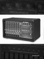 1
1
-
 2
2
-
 3
3
-
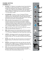 4
4
-
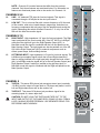 5
5
-
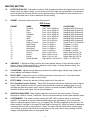 6
6
-
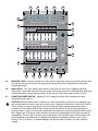 7
7
-
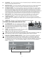 8
8
-
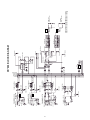 9
9
-
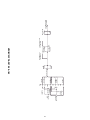 10
10
-
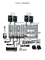 11
11
-
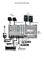 12
12
-
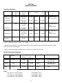 13
13
-
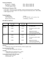 14
14
-
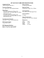 15
15
-
 16
16
-
 17
17
-
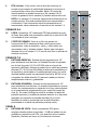 18
18
-
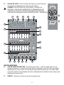 19
19
-
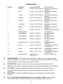 20
20
-
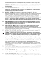 21
21
-
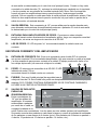 22
22
-
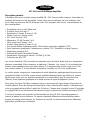 23
23
-
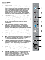 24
24
-
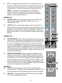 25
25
-
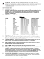 26
26
-
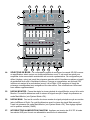 27
27
-
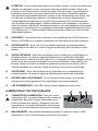 28
28
-
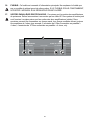 29
29
-
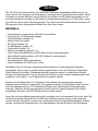 30
30
-
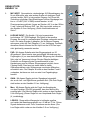 31
31
-
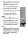 32
32
-
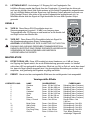 33
33
-
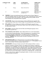 34
34
-
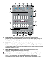 35
35
-
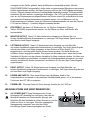 36
36
-
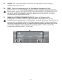 37
37
-
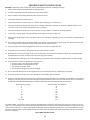 38
38
-
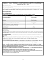 39
39
-
 40
40


Peavey XR 696 Manual de usuario
- Categoría
- Amplificador de instrumentos musicales
- Tipo
- Manual de usuario
en otros idiomas
- français: Peavey XR 696 Manuel utilisateur
- English: Peavey XR 696 User manual
- Deutsch: Peavey XR 696 Benutzerhandbuch
Artículos relacionados
-
Peavey XR 684F Manual de usuario
-
-
-
Peavey PV 6 Compact Mixer Manual de usuario
-
-
-
-
-
-