Char-Broil 463277519 Guía de instalación
- Categoría
- Barbacoas
- Tipo
- Guía de instalación
Este manual también es adecuado para

1
MODEL
MODELO
463277519
463278519
SERIAL NUMBER
NÚMERO DE SERIE
• See rating label on grill for serial number.
• El número de serie se encuentra en la etiqueta
deespecificaciones de la parrilla.
DATE PURCHASED
FECHA DE COMPRA
PRODUCT GUIDE
GUíA DEL PRODUCTO
If you have questions or need assistance during assembly, please call 1-800-448-2177
Si tiene alguna pregunta o si Necesita ayuda durante el Ensamblado, llámenos Al 1-800-448-2177
©
2018 Char-Broil, LLC. Columbus, GA, 31904. Printed in China. Imprimé en Chine. Impreso en China.
9/13/18 • G622-001-010801
MEDALLION BUILT-IN GRILL
4 & 5 BURNER
MEDALLION PARRILLA INCORPORADA
4 y 5 QUEMADOR
Easily converts from (NG) Natural Gas to (LP) liquid propane.
Se convierte fácilmente de (NG) gas natural a (LP) propano líquido.
NOTE: If you are planning to convert your grill from Natural Gas to Propane
Gas, it is highly recommended that you perform the conversion BEFORE grill
installation.
NOTA: Si planea convertir su parrilla de Gas Natural a Gas Propano, se
recomienda encarecidamente que realice la conversión ANTES de la insta-
lación de la parrilla.
CONVERSION KIT | KIT DE CONVERSION
#2429018
463277519
463278519

CHARBROIL.COMPage 2
CAUTION
WARNING
CONTENTS
IMPORTANT SAFETY
INFORMATION
SAFETY SYMBOLS
DANGER, WARNING, and CAUTION state-
ments are used throughout this Owner’s Manual
to emphasize critical and important information.
Read and follow these statements to help ensure
safety and prevent property damage.
The statements are defined below.
THIS GRILL IS FOR OUTDOOR USE ONLY
If you smell gas:
1. Shut off gas to the appliance
2. Extinguish any open flame.
3. Open lid.
4. If odor continues, keep away from the appliance and
immdiately call your gas supplier or your fire department.
WARNING: Indicates a potentially hazardous situation which, if
not avoided, could result in death or serious injury.
1. Do not store or use gasoline or other flammable liquids or
vapors in the vicinity of this or any other appliance.
2. An LP cylinder not connected for use shall not be stored in
the vicinity of this or any other appliance.
CAUTION: Indicates a potentially hazardous situation or unsafe
practice which, if not avoided, may result in minor or moderate
injury.
DANGER: Indicates a imminently hazardous situation which, if
notavoided, will result in death or serious injury.
DANGER
DANGER
WARNING
IMPORTANT SAFETY INFORMATION PAGE 2
FOR YOUR SAFETY - INSTALLING YOUR GRILL. PAGE 3
PLANNING FOR INSTALLATION PAGE 4
LEAK CHECKING YOUR GRILL PAGE 7
FOR YOUR SAFETY - OPERATING YOUR GRILL PAGE 8
FOR YOUR SAFETY - LIGHTING YOUR GRILL PAGE 9
CARE AND MAINTENANCE OF GRILL PAGE 10
GRILL LIGHTS - OPERATION AND BULB REPLACEMENT PAGE 11
REPLACEMENT PARTS DIAGRAM - 463278519 PAGE 22
REPLACEMENT PARTS LIST - 463278519 PAGE 23
REPLACEMENT PARTS DIAGRAM - 463277519 PAGE 25
REPLACEMENT PARTS LIST - 463277519 PAGE 26
GRILL ASSEMBLY - 463278519 PAGE 28
GRILL ASSEMBLY - 463277519 PAGE 32
TROUBLESHOOTING PAGE 37
LIMITED WARRANTY PAGE 41
REGISTRATION CARD PAGE 43

CHARBROIL.COMPage 3
• Keep grill area clear and free from materials that
burn.
• Use grill only in well-ventilated space.
• NEVER use in enclosed space such as carport,
garage, porch, covered patio, or under an over-
head combustible structure of any kind.
• Maintain 10 ft. clearance to objects that can
catch fire or sources of ignition such as pilot
lights on water heaters, live electrical appliances,
etc.
• Failure to follow all manufacturer’s instructions
could result in serious personal injury and/or
property damage.
• This outdoor gas appliance is not intended to be
installed in or on a boat or Recreational Vehicle.
• Never attempt to attach this grill to the self-con-
tained LP gas system of a camper trailer or motor
home.
• Keep ventilation openings in cylinder enclosure
(grill cart) free and clear of debris.
• Use grill at least 3 feet (90 cm) from any wall
or surface.
KEEP AREA
ABOVE THE
GRILL CLEAR!
36” (90CM)
36” (90CM)
36” (90CM)
36” (90CM)
Perform the following checks prior to the first
use of your grill:
• Make sure valves are inside the venturi tubes of
the burners as shown.
• Always ensure the control knobs pop up and lock
into the OFF position. Turn the tank valve on
PRIOR to turning on the control knobs to avoid
ignition problems and low flames.
• Perform a leak check as documented in the
“Leak Checking Your Grill” section.
• Check burner tubes for spider nests per the Care
and Mainentance of your Grill section.
Valve
Venturi
Tube
CAUTION
For residential use only. Do not use for commercial
cooking.
Read and follow all safety statements, assembly
instructions, and use and care directions before
attempting to assemble and cook.
Some parts may contain sharp edges. Wear protec-
tive gloves if necessary.
• NEVER store a spare LP cylinder under or near
the appliance or in an enclosed area.
• An over filled or improperly stored cylinder is
a hazard due to possible gas release from the
safety relief valve. This could cause an intense
fire with risk of property damage, serious injury
or death.
• If you see, smell or hear gas escaping, immedi-
ately get away from the LP cylinder/appliance
and call your fire department.
Installation Safety
Precautions
• Use grill, as purchased, only with Natural gas
and the regulator supplied. If your grill is Dual
Fuel ready, a conversion kit must be purchased
for use with LP (propane) gas.
• Grill installation must conform with local codes,
or in their absence of local codes, with either
the National Fuel Gas Code, ANSI Z223.1/ NFPA
54, Natural Gas and Propane Installation Code,
CSA B149.1, or Propane Storage and Handling
Code, B149.2.
• All electrical accessories (such as rotisserie)
must be electrically grounded in accordance
with local codes, or National Electrical Code,
ANSI / NFPA 70 or Canadian Electrical Code,
CSA C22.1. Keep any electrical cords and/or
fuel supply hoses away from any hot surfaces.
• This grill is safety certified for use in the United
States and/or Canada only. Do not modify for
use in any other location. Modification will
result in a safety hazard.
FOR YOUR SAFETY - INSTALLING YOUR GRILL
WARNING
DANGER
WARNING

CHARBROIL.COMPage 4
PLANNING FOR INSTALLATION
LOCATION PLANNING
The following should be considered when determining where to place your new
built-in grill outdoor grill enclosure construction. It is best to identify the location
of the grill prior to beginning any set up.
• Plan for easy access to the house considering weather conditions like
frequent rain or snow that would make it more convenient to have the grill
located close to an entryway.
• Be sure to allow space for entertaining around the sides of the grill as it will
become a gathering area during outdoor events.
• Ventilation is a key to the grill’s performance and smoke exhaust should be
considered when identifying a location.
• The grill will smoke so consider the prevailing wind direction and position the
grill so wind blows toward the front of the grill to move the smoke away and
provide adequate airflow.
• Do not place the grill under or near windows that may be opened to your
house as smoke will enter easily.
Ensuring proper Combustion Air and Cooling Airflow
• Proper airflow MUST be maintained for the grill to perform as it was
designed. If airflow is blocked, overheating and poor combustion will result.
GRILL INSTALLATION
WARNING
FOR LP GAS CONVERSION:
• Conversion to LP gas must be performed by a certified gas technician.
• LP Conversion Kit Model must be used. Specific details for enclosure
construction are included in the conversion kit instructions.
• Additional enclosure venting construction is required.
NOTE: ENCLOSURE MUST BE CONSTRUCTED OF NON-COM-
BUSTIBLE MATERIALS.
BUILDING THE ENCLOSURE:
• NOTE: If this grill is to be used as a replacement grill in an existing grill
enclosure, consult your local contractor to determine if the grill will work
correctly with your existing enclosure.
• Four “L” brackets are supplied for securing the grill to the enclosure.
• If grill enclosure design permits fastners only, four holes are provided on
bottom flange.
• Consult the table below for enclosure cut-out dimensions.
• The left rear corner of the enclosure must be open for gas connection
clearance. See Figures below.
NOTE: Area directly beneath the grill must be open. No solid surface.
Grill Model Dim. A Dim. B Dim. C Dim. D Dim. E
463278519
4 Burner
34 7/8”
885mm
21.5/8”
548mm
11”
279mm
14 9/16”
370mm
33 7/16”
848
463277519
5 Burner
41.75”
1060mm
21.5/8”
548mm
11”
279mm
14 9/16”
370mm
40 5/16”
1023mm
Dim. C
2.0” (50MM)
FRONT OF ENCLOSURE CUTOUT SHOWN
Dim. B
1.75” (44mm)
TOP OF ENCLOSURE CUTOUT SHOWN
Dim. A
2.5” (63mm)
1” minimum
Dim. D
Dim. E
BOTTOM OF GRILL SHOWN

CHARBROIL.COMPage 5
PLANNING FOR INSTALLATION
Grill shown installed in island
ELECTRONIC CONTROL MODULE:
NOTE: A licensed electrician should be used to install the ignition module and
make any wiring extensions or modifications.
• This grill has been supplied with 23” (60cm) of wire to mount the control
module in the right hand rear section of your grill enclosure. We recommend
that you mount the module to the rear wall of your enclosure.
MOUNT TO
REAR WALL
IMPORTANT
NATURAL GAS CONNECTIONS AND SERVICE REGU-
LATORS ABOVE 1/2 PSI:
Prior to 1998, all residential gas service regulators were set with an outlet
pressure of 7 inches water column. In the 1998 edition of NFPA 54, the National
Fuel Gas Code, a change was made allowing service regulators of 2 and 5 psi.
With this change it was also required that an in line regulator be connected
between the service regulator and the appliance regulator if the 2 or 5 psi system
is used. This additional regulator is not supplied with the product. It is possible for
a consumer, making the connection themselves, or a plumber, not checking, to tap
into a 2 or 5 psi line. If a pressure of 2 psi or greater is supplied to the appliance
regulator on certain grills it will shut down and not deliver any gas to the grill. The
included quick disconnect socket and hose should not be used at pressures above
1/2 psi
If the grill is properly connected and still not getting gas, delivery pressure needs
to be verified. If pressure is greater than 1/2 psi, make sure that an in line regu-
lator is present. Once the grill has been over-pressured, the regulator may or may
not have been damaged. The best practice is to replace the regulator.A natural gas
regulator rated at 4” water column is supplied with your grill. If you do not plan to
convert your grill to LP (propane) - This is the only regulator that should be used.
Note that this regulator can not be used for LP (propane)
CAUTION
The grill model 463278519 and model 463277519 are set for use with natural
gas. Both appliances are designed for conversion to LP gas also. CONVERSION
TO LP GAS MUST BE PERFORMED BY A CERTIFIED GAS TECHNICIAN. LP conver-
sion kit model 2429018 must be used (sold separately).
WARNING
The outdoor grill must be disconnected from the natural gas supply piping system
during any pressure testing of the system in excess of ½ PSIG (3.5 kPa). The out-
door grill must be isolated from the natural gas supply piping system by closing
all individual shut-off valves during any pressure testing of the system equal to or
less than ½ PSIG (3.5 kPa). Never connect the grill to an unregulated gas supply.
CONNECTING THE NATURAL GAS SUPPLY LINE:
Step 1: Correctly Sizing the Natural Gas Supply Line
In most cases, a pipe diameter of ½” to ¾” is sufficient to connect your outdoor
grill to your home’s natural gas supply system. The correct pipe size depends on
the following:
1. The overall length of your home’s natural gas supply pipe run
2. The connection point of your outdoor grill into your home’s natural gas supply
system with respect to placement of natural gas appliances in your home
3. The desired distance of the outdoor grill from your home’s natural gas supply
4. The combined total BTU rate of all the natural gas appliances in your home.
A certified gas technician will be able to recommend the appropriate gas pipe size
and length to connect your outdoor grill to your home gas supply. The BTU rate of
the grill is 40,000 BTU/hr for model 463278519 and 45,000 BTU/hr for model
463277519.
Step 2: Placement of the Manual Shut-off Valve
It is recommended that a manual shut-off valve that is sized correctly for the
gas supply pipe be installed outside the grill enclosure. This valve will allow safe
access to shut off the natural gas supply to the built in grill in the event of an
emergency. A convenient location for the safety valve is at the rear of the grill

CHARBROIL.COMPage 6
PLANNING FOR INSTALLATION
enclosure. This allows for easy access to connect the gas piping in the enclosure
to the shut-off valve. If a gas supply stub-up is used inside the grill enclosure,
an external shut-off valve close to the grill is still recommended.
NOTE: A licensed plumber should be used to install the gas
supply line to the grill.
The gas supply line from your home should be routed to the left rear corner of
the grill inside the grill enclosure. It is recommended that hard piping be used to
connect to the inlet of the natural gas appliance regulator. Constant movement
of flexible gas lines could cause fatiguing of the flexible line and result in gas
leakage. If hard piping is not used for the home supply line, any flexible gas
lines must be supported within the enclosure to prevent constant movement and
fatiguing.
PRIOR TO INSTALLING THE GRILL IN THE ENCLOSURE:
1. Turn the home gas source to the OFF position.
2. Install the supplied 4 inch water column regulator to your hard piped,
natrual gas supply line. It is recommended that the regulator be located
inside the grill enclosure. The inlet and outlet sides fo the the regulator are
noted by markings on the regulator body. SEE FIGURE A.
3. The grill is now ready to be installed in the enclosure. Take care not to
damage the regulator during installation. Two persons are required to lift the
grill and place in the enclosure.
Gas In
Gas Shut off Valve
Regulator
Hard Pipe
Enclosure
Grill
FIGURE A
AFTER INSTALLING THE GRILL IN THE ENCLOSURE:
1. Use hard pipe with adapters or flexible tubing with adapters to connect the
outlet of the regulator to the grill’s 5/8” gas flare fitting. Adapters, fittings or
tubing are not supplied. See FIGURE B for piping suggestions.
2. Confirm all grill control knobs are turned to OFF.
3. Turn ON the home gas source.
4. Proceed to Leak Testing.
FIP to
Male flare
adapter
FIGURE B
R RR
Hose with
female flare
fittings
Male flare fitting at grill
FIP to
Male flare
adapter
MIP to
Male flare
adapter

CHARBROIL.COMPage 7
LEAK CHECKING YOUR GRILL
Leak Testing
1. Turn all grill control knobs to OFF.
2. Turn ON the home gas source.
3. Use a clean paint brush and a 50/50 mild soap and water solution. Brush soapy solution onto areas indicated. (see Figure C).
4. If “growing” bubbles appear, there is a leak. Close main gas supply and re-tighten all connections. If leaks cannot be stopped do not try to repair. Contact licensed
plumber for correction.
5. The appliance and its individual shut off valve must be disconnected from the gas supply piping system during any pressure testing on that system at test pressures in
excess of ½ psig (3.5kPa).
6. The appliance must be isolated from the gas supply piping system by closing its individual manual shut off valve during any pressure testing of the gas supply piping
system at test pressures equal to or less than ½ psig (3.5kPa).
7. IMPORTANT: You should leak check each piping connection.
R
FIGURE C
Example of “Growing” Bubbles
indicating a gas leak.
Regulator
Grill Connection
Gas Shut off Valve
Gas Supply piping
Grill
Enclosure
Check for
leaks here
Check for
leaks here
Check for
leaks here
Check for
leaks here
Check for
leaks here
IMPORTANT: You should leak
check each piping connection.
Examples of possible locations
are shown here with a
IMPORTANT: You should leak
check each piping connection.
Examples of possible locations
are shown here with a

CHARBROIL.COMPage 8
FOR YOUR SAFETY - WHILE OPERATING YOUR GRILL
For Safe Use of Your Grill and to Avoid
Serious Injury:
• Controls and gas source or tank OFF when not
in use.
• Do not let children operate or play near grill.
• Check burner flames regularly.
• Do not use charcoal or ceramic briquets in a gas
grill.
• Do not cover grates with aluminum foil or any other
material. This will block burner ventilation and
create a potentially dangerous condition resulting
in property damage and/or personal injury.
• NEVER attempt to light or re-light burner with
lid closed. A buildup of non-ignited gas inside a
closed grill is hazardous.
• If you see, smell or hear gas escaping, immediately
get away from the appliance and call your fire
department.
• If during operation the flames go out (You smell
gas or cannot see the flame):
1. Turn the burner controls OFF.
2. Open lid.
3. Wait 5 minutes and repeat the lighting
procedure.
• If the burner goes out, gas will continue to flow
out of the burner and could accidently ignite with
risk of injury.
• Do not attempt to repair or alter the natural gas
regulator for any “assumed” defect. Any modi-
fication to this assembly will void your warranty
and create the risk of a gas leak and fire. Use only
authorized replacement parts supplied by manu-
facturer.
• Putting out grease fires by closing the lid is not
possible. Grills are well ventilated for safety
reasons.
• Do not use water on a grease fire. Personal injury
may result. If a grease fire develops, turn knobs
and gas supply off.
• Do not leave grill unattended while preheating or
burning off food residue on HI. If grill has not been
regularly cleaned, a grease fire can occur that may
damage the product.
• The best way to prevent grease fires is regular
cleaning of the grill following instructions on
General Grill Cleaning and Cleaning The Burner
Assembly.
WARNING
DANGER
CAUTION
Before each use of your Grill:
Perform a Valve Check
• Important: Make sure gas is off at gas supply
before checking valves. Knobs lock in off posi-
tion. To check valves, first push in knobs and release,
knobs should spring back. If knobs do not spring
back, replace valve assembly before using grill. Turn
knobs to LOW position then turn back to off position.
Valves should turn smoothly.
Check the Ignitor
• Turn gas off at gas supply. Press and hold electronic
ignitor button. “Click” should be heard and spark
seen each time in each collector box or between
burner and electrode. See “Troubleshooting” if no
click or spark.
Burner Flame Check
• Remove cooking grates and heat tents. Light
burners, rotate knobs from HIGH to LOW. You should
see a smaller flame in LOW position than seen on
HIGH. Perform burner flame check on side burner,
also. Always check flame prior to each use. If only
low flame is seen refer to “Sudden drop or low
flame” in the Troubleshooting Section.
HIGH
LOW
Turning your Grill Off
• Turn all knobs to the OFF position. Turn gas
supply off by turning hand-wheel clockwise to a full
stop.
Checking the Fuel Gas Hose
• If you have converted your grill for use with LP
(propane) gas, check to see if hoses are cut, worn,
or kinked, Replace damaged hoses before using
your grill. Use only replacement hose specified by
the manufacturer.

CHARBROIL.COMPage 9
LIGHTING THE MAIN BURNERS
FOR YOUR SAFETY - LIGHTING YOUR GRILL
Main Burner Ignitor Lighting
• Do not lean over the grill while lighting.
1. Turn gas burner control valves to (OFF).
2. Open lid during lighting or re-lighting.
3. Turn ON gas at supply valve.
4. To ignite, push and turn burner knob to HIGH. Immediately, push and hold
ELECTRONIC IGNITOR button until the burner lights.
5. If ignition does NOT occur in 5 seconds, turn the burner controls OFF ,
wait 5 minutes and repeat the lighting procedure.
6. Repeat steps 4 and 5 to light other main burners.
Main Burner Match-Lighting
• Do not lean over the grill while lighting.
1. Turn gas burner control valves to (OFF).
2. Open lid during lighting or re-lighting.
3. Turn ON gas at supply valve.
4. Place match into match holder (Located inside of grease tray). Light match;
then light burner by placing match through the rectangular hole in the cooking
grate. Immediately push in and turn burner knob to the HIGH position. Be
sure burner lights and stays lit.
5. Light adjacent burners in sequence by pushing knobs in and turning to the
HIGH position.
NOTE: 4 Burner Grill shown, follow the same
steps for the 5 Burner grill.
NOTA: Se muestra la parrilla de 4 quema-
dores, siga los mismos pasos para la parrilla
de 5 quemadores.

CHARBROIL.COMPage 10
Cleaning the Burner Assembly
Follow these instructions to clean and/or replace parts of burner assembly or if you
have trouble igniting griddle.
1. Turn gas off at control knobs and turn off gas at gas supply.
2. Remove griddle plate.
3. Remove hardware securing burners.
4. Remove Carryover tubes. Note that your grill’s carryover tubes may be located
at the front of the grill. Removal is the same, whther at the front or the rear.
5. Detach electrode from burner.
6. Carefully lift each burner up and away from valve openings.
We suggest three ways to clean the burner tubes. Use the one easiest for you.
• Bend a stiff wire (a light weight coat hanger works well) into a small
hook. Run the hook through each burner tube several times.
• Use a narrow bottle brush with a flexible handle (do not use a brass wire
brush). Run the brush through each burner tube several times.
• Wear eye protection: Use an air hose to force air into the burner tube
and out the burner ports. Check each port to make sure air comes out
each hole.
7. Wire brush entire outer surface of burner to remove food residue and dirt.
8. Clean any blocked ports with a stiff wire such as an open paper clip.
9. Check burner for damage due to normal wear and corrosion, some holes may
become enlarged. If any large cracks or holes are found, replace burner.
VERY IMPORTANT: Burner tubes must re-engage valve openings. See illus-
tration below.
10. Attach electrode to burner.
11. Carefully replace burners.
12. Attach burners to brackets on firebox.
13. Reposition carryover tubes and attach to burners. Replace heat tents and cook-
ing grates.
14. Before cooking again on griddle, perform a “Leak Test” and “Burner Flame
Check”.
STEP 5: Example of a bent, stiff
wire for cleaning your burner.
STEP 10: CORRECT BURNER
TO VALVE ENGAGEMENT
FIREBOX BURNER
SUPPORT
CARRYOVER TUBE
FIREBOX
Pry off electode with a
flat blade screwdriver.
Electrode
CARE AND MAINTENANCE OF YOUR GRILL

CHARBROIL.COMPage 11
GRILL LIGHTS - OPERATION AND BULB REPLACEMENT
Light Operation
• If your grill is hot, make sure the grill has been turned OFF and allowed to cool.
• Ensure the Grill Light Switch is in the OFF position.
• Connect the light plug to an extension cord, then put the extension cord plug into the wall
receptacle.
• Turn the light switch ON
Bulb Replacement
• Make sure light switch on the control panel is in the OFF position and adapter plug is
disconnected from outlet.
1. Release the screw securing the light socket.
2. Take out the socket and remove the lens.
3. Loosen the two screws which are locking the bulb. NOTE: Skip step 3 if there is no screw
locking the bulb.
4. Pull out the old bulb.
5. Before handling the new bulb, put on a pair of cotton gloves. The oils from your hands can
damage or shorten the life of your new bulb.
6. Install the new bulb.
7. Reverse instructions from step 3 through step 1 to re-install socket.
Cleaning the Lens
1. Prior to cleaning, make sure grill has been turned off, cooled, and the light switch is in the
“OFF” position and the light plug is disconnected from the power supply.
2. Do not clean the glass lens when warm. Allow to cool before cleaning. Sudden change in
temperature may cause cracking of the glass lens.
3. Use a damp towel to clean the surface of the glass lens.
4. Allow the lens to dry before reconnecting the light plug to the power supply and turning the
light switch to the “ON” position.
WARNING
• Keep any electrical supply cord away from any heated surface.
• Use the shortest length extension cord required. Do not connect 2 or more extension cords
together.
• To protect against electric shock, do not immerse cord or plugs in water or other liquid.
• Unplug from the outlet when not in use and before cleaning. Allow to cool before putting on
or taking off parts.
• Do not operate grill with a damaged cord, plug, or after the appliance malfunctions or has
been damaged in any manner.
• Do not let the cord hang over the edge of a table or touch hot surfaces.
• Do not use an outdoor cooking gas appliance for purposes other than intended.
• When connecting, first connect plug to the outdoor cooking gas appliance then plug
appliance into the outlet.
• Use only a Ground Fault Interrupter(GFI) protected circuit with this outdoor cooking gas
appliance.
• Never remove the grounding plug or use with an adapter of 2 prongs.
• Use only extension cords with a 3 prong grounding plug, rated for the power of the equip-
ment, and approved for outdoor use with a W-A marking.
1
2
3
Loosen the two screws which
are locking the bulb, if needed.
4
Bulb Specification
Bulb Type: Halogen
Wattage: 10 Watts per bulb
Voltage: 12 V

CHARBROIL.COMPágina 12
PRECAUCIÓN
ADVERTENCIA
CONTENIDO
INFORMACIÓN IMPORTANTE
DE SEGURIDAD
SÍMBOLOS DE SEGURIDAD
Las indicaciones de PELIGRO, ADVERTENCIA y
PRECAUCIÓN se utilizan a lo largo de este Manual
del propietario para enfatizar información crítica e
importante. Lea y siga estas indicaciones para ayudar a
garantizar la seguridad y evitar daños a la propiedad.
Las indicaciones se definen a continuación.
ESTA PARRILLA ES SOLO PARA USO EN EXTERIORES
Si huele a gas:
1. Cierre el suministro de gas al aparato
2. Extinga cualquier llama abierta.
3. Abra la tapa.
4 Si el olor continúa, manténgase alejado del aparato y llame
inmediatamente a su proveedor de gas o a su departamento de
bomberos.
ADVERTENCIA: Indica una situación potencialmente peligrosa que, si
no se evita, podría provocar la muerte o lesiones graves.
1. No almacene ni use gasolina u otros líquidos o vapores inflamables
cerca de este o cualquier otro aparato.
2. Un cilindro de LP no conectado para su uso no debe almacenarse
cerca de este ni de ningún otro aparato.
PRECAUCIÓN: Indica una situación potencialmente peligrosa o prác-
tica insegura que, si no se evita, puede dar como resultado una lesión
menor o moderada.
PELIGRO: Indica una situación inminentemente peligrosa que, si no
se evita, ocasionará la muerte o lesiones graves.
PELIGRO
PELIGRO
ADVERTENCIA
INFORMACIÓN IMPORTANTE DE SEGURIDAD PÁGINA 12
PARA SU SEGURIDAD, INSTALACIÓN DE SU PARRILLA. PÁGINA 13
PLANIFICACIÓN PARA LA INSTALACIÓN PÁGINA 14
CONTROLAR LAS FUGAS DE SU PARRILLA PÁGINA 17
PARA SU SEGURIDAD, OPERAR SU PARRILLA PÁGINA 18
PARA SU SEGURIDAD, ENCENDER SU PARRILLA PÁGINA 19
CUIDADO Y MANTENIMIENTO DE SU PARRILLA PÁGINA 20
LUCES DE LA PARRILLA - FUNCIONAMIENTO Y SUSTITUCIÓN DE BOMBI-
LLAS PÁGINA 21
DIAGRAMA DE PIEZAS DE REPUESTO - 463278519 PÁGINA 22
LISTA DE PIEZAS DE REPUESTO - 463278519 PÁGINA 24
DIAGRAMA DE PIEZAS DE REPUESTO PÁGINA 25
LISTA DE PIEZAS DE REPUESTO - 463277519 PÁGINA 27
MONTAJE DE LA PARRILLA - 463278519 PÁGINA 28
MONTAJE DE LA PARRILLA - 463277519 PÁGINA 32
SOLUCIÓN DE PROBLEMAS PÁGINA 39
GARANTÍA LIMITADA PÁGINA 41
TARJETA DE REGISTRO PÁGINA 43

CHARBROIL.COMPágina 13
• Mantenga el área de la parrilla despejada y libre de
materiales que se quemen.
• Use la parrilla solo en espacios bien ventilados.
• NUNCA la use en espacios cerrados tales como
garaje, garaje, porche, patio cubierto o debajo de una
estructura combustible superior de ningún tipo.
• Mantenga un espacio libre de 10 pies sobre los objetos
que puedan incendiarse o sobre las fuentes de igni-
ción, como luces piloto en los calentadores de agua,
electrodomésticos, etc.
• El incumplimiento de todas las instrucciones del fabri-
cante podría ocasionar lesiones personales graves y/o
daños a la propiedad.
• Este aparato de gas para exteriores no está diseñado
para instalarse sobre o dentro de un bote o vehículo
recreativo.
• Nunca intente conectar esta parrilla al sistema autó-
nomo de gas LP de un remolque o autocaravana.
• Mantenga las aberturas de ventilación en el recinto del
cilindro (carro de la parrilla) libres de residuos.
• Use la parrilla por lo menos a 3 pies (90 cm) de cual-
quier pared o superficie.
¡MANTENGA
LIBRE EL ÁREA
POR ENCIMA DE
LA PARRILLA!
36” (90CM)
36” (90CM)
36” (90CM)
36” (90CM)
Realice las siguientes verificaciones antes del primer
uso de su parrilla:
• Asegúrese de que las válvulas estén dentro de los
tubos venturi de los quemadores, como se muestra.
• Asegúrese siempre de que las perillas de control
se abren y se bloquean en la posición de OFF
(APAGADO). Encienda la válvula del tanque ANTES de
encender las perillas de control para evitar problemas
de encendido y llamas bajas.
• Realice una comprobación de fugas tal como se docu-
menta en la sección "Comprobación de fugas en la
parrilla".
• Verifique los tubos del quemador en busca de nidos de
arañas siguiendo la sección de Cuidado y manteni-
miento de su parrilla.
Válvula
Tubo
venturi
PRECAUCIÓN
Solo para uso residencial. No usar para cocina comercial.
Lea y siga todas las declaraciones de seguridad, las instruc-
ciones de montaje, y las instrucciones de uso y cuidado
antes de intentar armar y cocinar.
Algunas partes podrían contener bordes filosos. Use
guantes protectores si es necesario.
• NUNCA almacene un cilindro de LP de repuesto
debajo o cerca del aparato o en un área cerrada.
• Un cilindro llenado en exceso o almacenado inco-
rrectamente es un peligro debido a la posible libe-
ración de gas de la válvula de alivio de seguridad.
Esto podría causar un incendio intenso con riesgo
de daños a la propiedad, lesiones graves o la muerte.
• Si ve, huele o escucha un escape de gas, aléjese
inmediatamente del cilindro de LP/aparato y llame
a su departamento de bomberos.
•
Precauciones de segu-
ridad de instalación
• Use la parrilla, tal como se compró, solo con gas
natural y el regulador suministrado. Si su parrilla
está preparada para usar combustible dual, se debe
comprar un kit de conversión para usar con gas LP
(propano).
• La instalación de la parrilla debe cumplir con los
códigos locales, o en ausencia de códigos locales,
ya sea con el Código Nacional de Gas Combustible,
ANSI Z223.1/ NFPA 54, Código de Instalación de Gas
Natural y Propano, CSA B149.1 o Código de Almacena-
miento y Manipulación de Propano, B149.2.
• Todos los accesorios eléctricos (como el asador)
deben conectarse a tierra de acuerdo con los códigos
locales o el Código Eléctrico Nacional, ANSI / NFPA
70 o el Código Eléctrico Canadiense, CSA C22.1.
Mantenga los cables eléctricos y/o las mangueras
de suministro de combustible lejos de las superficies
calientes.
• Esta parrilla está certificada de seguridad para su
uso en los Estados Unidos y/o Canadá solamente. No
la modifique para usarla en ninguna otra ubicación.
La modificación dará como resultado un riesgo de
seguridad.
PARA SU SEGURIDAD, INSTALACIÓN DE SU PARRILLA
ADVERTENCIA
PELIGRO
ADVERTENCIA

CHARBROIL.COMPágina 14
PLANIFICACIÓN PARA LA INSTALACIÓN
PLANIFICACIÓN DE LA UBICACIÓN
Se debe considerar lo siguiente al determinar dónde colocar su nueva para parrilla al
aire libre. Lo mejor es identificar la ubicación de la parrilla antes de comenzar cualquier
preparación.
• Planifique un acceso fácil a la casa teniendo en cuenta las condiciones climáticas,
como las frecuentes lluvias o nieve, que harían más conveniente tener la parrilla
ubicada cerca de una entrada.
• Asegúrese de dejar espacio para el entretenimiento a los lados de la parrilla, ya que
se convertirá en un área de reunión durante los eventos al aire libre.
• La ventilación es una clave para el rendimiento de la parrilla y se debe considerar el
escape de humo al identificar una ubicación.
• La parrilla humeará, así que tenga en cuenta la dirección predominante del viento y
coloque la parrilla de modo que el viento sople hacia la parte delantera de la parrilla
para alejar el humo y proporcionar un flujo de aire adecuado.
• No coloque la parrilla debajo o cerca de ventanas que puedan abrirse en su casa ya
que el humo entrará fácilmente.
Asegurando un flujo de aire de combustión y enfriamiento adecuados
• Un flujo de aire apropiado DEBE mantenerse para que la parrilla funcione tal como
fue diseñada. Si el flujo de aire está bloqueado, se producirá un sobrecalentamiento
y una combustión deficiente.
INSTALACIÓN DE LA PARRILLA
ADVERTENCIA
PARA LA CONVERSIÓN DE GAS LP:
• La conversión a gas LP debe ser realizada por un técnico de gas certificado.
• Se debe usar el modelo de kit de conversión LP. Los detalles específicos para la
construcción del recinto se incluyen en las instrucciones del kit de conversión.
• Se requiere una construcción adicional de ventilación del recinto.
NOTA: EL RECINTO DEBE ESTAR CONSTRUIDO DE MATERIALES NO
COMBUSTIBLES.
CONSTRUCCIÓN DEL RECINTO:
• NOTA: Si esta parrilla se va a utilizar como parrilla de reemplazo en un recinto
de parrilla existente, consulte a su contratista local para determinar si la parrilla
funcionará correctamente con su recinto existente.
• Se suministran cuatro soportes en "L" para asegurar la parrilla al recinto.
• Si el diseño del resisto de la parrilla solo permite sujetadores, se proporcionan cuatro
orificios en la brida inferior.
• Consulte la tabla a continuación para ver las dimensiones de corte del recinto.
• La esquina trasera izquierda del gabinete debe estar abierta para la separación de la
conexión de gas. Consulte las Figuras a continuación.
NOTA: El área directamente debajo de la parrilla debe estar abierta. Sin superficie sólida.
Modelo de parrilla Dim. A Dim. B Dim. C Dim. D Dim. E
463278519
4 quemadores
34 7/8”
885mm
21.5/8”
548mm
11”
279mm
14 9/16”
370mm
33 7/16”
848
463277519
5 Burner
41.75”
1060mm
21.5/8”
548mm
11”
279mm
14 9/16”
370mm
40 5/16”
1023mm
Dim. C
2.0” (50MM)
SE MUESTRA UNA VISTA DE RECORTE DE LA PARTE DELANTERA DEL
RECINTO
Dim. D
Dim. E
SE MUESTRA LA PARTE INFERIOR DE LA PARRILLA
Dim. B
1.75” (44mm)
SE MUESTRA UNA VISTA DE RECORTE DE LA PARTE SUPERIOR DEL
RECINTO
Dim. A
2.5” (63mm)

CHARBROIL.COMPágina 15
PLANIFICACIÓN PARA LA INSTALACIÓN
Parrilla mostrada instalada en una isla
MÓDULO DE CONTROL ELECTRÓNICO:
NOTA: Se debe usar un electricista con licencia para instalar el módulo de encendido y
realizar cualquier extensión o modificación del cableado.
• Esta parrilla se ha suministrado con 23” (60 cm) de cable para montar el módulo de
control en la sección trasera derecha de su gabinete para parrilla. Recomendamos que
monte el módulo en la pared posterior de su gabinete.
MONTAR EN PARED
POSTERIOR
IMPORTANTE
CONEXIONES DE GAS NATURAL Y REGULADORES DE SER-
VICIO POR ENCIMA DE 1/2 PSI:
Antes de 1998, todos los reguladores del servicio de gas residencial se establecieron
con una presión de salida de 7 pulgadas de columna de agua. En la edición de 1998
de NFPA 54, el Código Nacional de Gas Combustible, se realizó un cambio que permite
los reguladores de servicio de 2 y 5 psi. Con este cambio también se requirió que se
conectara un regulador en línea entre el regulador de servicio y el regulador del aparato si
se usa el sistema de 2 o 5 psi. Este regulador adicional no se suministra con el producto.
Es posible que un consumidor, haciendo la conexión por sí mismo, o un plomero, que no
esté revisando, toquen una línea de 2 o 5 psi. Si se suministra una presión de 2 psi o más
al regulador del electrodoméstico en ciertas parrillas, se apagará y no enviará ningún gas
a la parrilla. El enchufe y la manguera de desconexión rápida incluidos no deben usarse a
presiones superiores a 1/2 psi
Si la parrilla está conectada correctamente y aún no recibe el gas, la presión de entrega
debe verificarse. Si la presión es mayor de 1/2 psi, asegúrese de que haya un regulador en
la línea. Una vez que la parrilla ha sido presionada en exceso, el regulador podría o no ha-
ber sido dañado. La mejor práctica es reemplazar el regulador. Un regulador de gas natural
con una columna de agua de 4" se suministra con su parrilla. Si no planea convertir su
parrilla en LP (propano), este es el único regulador que debe usarse. Tenga en cuenta que
este regulador no se puede usar para LP (propano)
PRECAUCIÓN
La parrilla modelo 463278519 y modelo 463277519 están configuradas para usarse con
gas natural. Ambos aparatos también están diseñados para la conversión a gas LP. LA
CONVERSIÓN A GAS LP DEBE SER REALIZADA POR UN TÉCNICO DE GAS CERTIFICADO.
Se debe usar el kit de conversión LP modelo 2429018 (se vende por separado).
ADVERTENCIA
La parrilla al aire libre debe estar desconectada del sistema de tuberías de suministro de
gas natural durante cualquier prueba de presión del sistema que exceda ½ PSIG (3.5 kPa).
La parrilla al aire libre debe aislarse del sistema de tuberías de suministro de gas natural
cerrando todas las válvulas de cierre individuales durante cualquier prueba de presión del
sistema igual o menor a ½ PSIG (3.5 kPa). Nunca conecte la parrilla a un suministro de
gas no regulado.
CONEXIÓN A LA LÍNEA DE SUMINISTRO DE GAS NATURAL:
Paso 1: Dimensionar correctamente la línea de suministro de gas
natural
En la mayoría de los casos, un diámetro de tubería de ½ "a ¾" es suficiente para conectar
su parrilla al aire libre al sistema de suministro de gas natural de su casa. El tamaño
correcto de la tubería depende de lo siguiente:
1. La longitud total de la tubería de suministro de gas natural de su hogar
2. El punto de conexión de su parrilla al aire libre en el sistema de suministro de gas na-
tural de su casa con respecto a la colocación de aparatos de gas natural en su hogar
3. La distancia deseada de la parrilla al aire libre del suministro de gas natural de su
hogar
4. La tasa total combinada de BTU de todos los aparatos de gas natural en su hogar.
Un técnico de gas certificado podrá recomendar el tamaño y la longitud adecuados de la
tubería de gas para conectar su parrilla exterior al suministro de gas de su hogar. La tasa
de BTU de la parrilla es de 40,000 BTU/h para el modelo 463278519 y de 45,000 BTU/h
para el modelo 463277519.
Paso 2: Colocación de la válvula de cierre manual
Se recomienda instalar una válvula de cierre manual que tenga el tamaño correcto para
la tubería de suministro de gas fuera del gabinete de la parrilla. Esta válvula permitirá un
acceso seguro para cerrar el suministro de gas natural a la parrilla incorporada en caso de
una emergencia. Una ubicación conveniente para la válvula de seguridad está en la parte

CHARBROIL.COMPágina 16
PLANIFICACIÓN PARA LA INSTALACIÓN
posterior del gabinete de la parrilla. Esto permite un acceso fácil para conectar la tubería
de gas en el gabinete a la válvula de cierre. Si se usa un conector de suministro de gas
dentro del gabinete de la parrilla,
aún se recomienda una válvula de cierre externa cerca de la parrilla.
NOTA: Se debe usar un plomero con licencia para instalar la línea de
suministro de gas a la parrilla.
La línea de suministro de gas de su casa debe enrutarse a la esquina trasera izquierda
de la parrilla dentro del recinto de la parrilla. Se recomienda utilizar tuberías duras para
conectar a la entrada del regulador del aparato de gas natural. El movimiento constante de
líneas de gas flexibles podría causar fatiga de la línea flexible y provocar fugas de gas. Si
no se utilizan tuberías duras para la línea de suministro doméstico, todas las líneas de gas
flexibles deben estar apoyadas dentro del recinto para evitar el movimiento constante y la
fatiga.
ANTES DE INSTALAR LA PARRILLA EN EL RECINTO:
1. Coloque la fuente de gas de la casa en la posición OFF.
2. Instale el regulador de columna de agua de 4 pulgadas suministrado a su línea de
suministro de gas natural y con una tubería dura. Se recomienda que el regulador
esté ubicado dentro del recinto de la parrilla. Los lados de entrada y salida del
regulador se notan mediante marcas en el cuerpo del regulador. CONSULTE LA
FIGURA A.
3. La parrilla ahora está lista para ser instalada en el recinto. Tenga cuidado de no
dañar el regulador durante la instalación. Se requieren dos personas para levantar la
parrilla y colocarla en el recinto.
Entrada de gas
Válvula de cierre
de gas
Regulador
Tubería dura
Recinto
Parrilla
FIGURA A
DESPUÉS DE INSTALAR LA PARRILLA EN EL RECINTO:
1. Use tubos duros con adaptadores o tubos flexibles con adaptadores para conectar
la salida del regulador al conector de gas de 5/8" de la parrilla. No se suministran
adaptadores, accesorios o tubos. Vea la FIGURA B para sugerencias de tuberías.
2. Confirme que todas las perillas de control de la parrilla estén en la posición OFF.
3. Encienda la fuente de gas del hogar.
4. Proceda con la prueba de fugas.
FIP a
adaptador de
llama macho
FIGURA B
R RR
Manguera con
conectores de
llama hembra
Conector de llama macho en la parrilla
FIP a
adaptador
de
llama
macho
MIP a
adaptador de
llama macho

CHARBROIL.COMPágina 17
CONTROLAR LAS FUGAS DE SU PARRILLA
Prueba de fugas
1. Gire todas las perillas de control de la parrilla a la posición O F F.
2. Encienda la fuente de gas del hogar.
3. Use un pincel limpio, y una solución de agua y jabón suave 50/50. Cepille la solución jabonosa en las áreas indicadas (ver figura C).
4. Si aparecen burbujas "crecientes", hay una fuga. Cierre el suministro principal de gas y vuelva a apretar todas las conexiones. Si las fugas no se pueden detener, no
intente repararlas. Póngase en contacto con un plomero autorizado para su corrección.
5. El aparato y su válvula de cierre individual deben desconectarse del sistema de tuberías de suministro de gas durante cualquier prueba de presión en ese sistema a
presiones de prueba superiores a ½ psig (3.5 kPa).
6. El aparato debe aislarse del sistema de tuberías de suministro de gas cerrando su válvula de cierre manual individual durante cualquier prueba de presión del sistema
de tuberías de suministro de gas a presiones de prueba iguales o menores a ½ psig (3.5 kPa).
7. IMPORTANTE: Debe verificar si hay fugas en cada conexión de tubería.
R
FIGURA C
Ejemplo de burbujas "cre-
cientes" que indican una
fuga de gas.
Regulador
Conexión a la parrilla
Válvula de cierre
de gas
Tubería de suministro
de gas
Parrilla
Recinto
Compruebe
si hay fugas
aquí
Compruebe si
hay fugas aquí
Compruebe si
hay fugas aquí
Compruebe si
hay fugas aquí
Compruebe si
hay fugas aquí
IMPORTANTE: Debe verificar
si hay fugas en cada cone-
xión de tubería. Algunos
ejemplos de posibles ubica-
ciones se muestran aquí con
un
IMPORTANTE: Debe verificar
si hay fugas en cada cone-
xión de tubería. Algunos
ejemplos de posibles ubica-
ciones se muestran aquí con
un

CHARBROIL.COMPágina 18
PARA SU SEGURIDAD, OPERAR SU PARRILLA
Para un uso seguro de su parrilla y para
evitar lesiones graves:
• Los controles y la fuente de gas o el tanque deben
estar en la posición OFF cuando no están en
uso.
• No permita que los niños operen o jueguen cerca
de la parrilla.
• Compruebe las llamas del quemador regularmente.
• No use briquetas de carbón o cerámica en una
parrilla a gas.
• No cubra las parrillas con papel de aluminio ni
ningún otro material. Eso bloqueará la ventilación
del quemador y creará una condición potencial-
mente peligrosa que resultará en daños a la propie-
dad y/o lesiones personales.
• NUNCA intente encender o volver a encender el
quemador con la tapa cerrada. Una acumulación
de gas no encendido dentro de una parrilla cerrada
es peligroso.
•
• Si ve, huele o escucha un escape de gas, aléjese
inmediatamente del aparato y llame a su departa-
mento de bomberos.
• Si durante el funcionamiento las llamas se apagan
(huele a gas o no puede ver la llama):
1. Coloque los controles del quemador en la
posición de OFF.
2. Abra la tapa.
3. Espere 5 minutos y repita el procedi-
miento de encendido.
• Si el quemador se apaga, el gas continuará
saliendo del quemador y podría encenderse acci-
dentalmente con riesgo de lesiones.
• No intente reparar o alterar el regulador de gas
natural por ningún defecto "asumido". Cualquier
modificación a este montaje anulará su garantía y
creará un riesgo de fuga de gas e incendio. Use
solo repuestos autorizados suministrados por el
fabricante.
• No es posible apagar los fuegos de grasa cerrando
la tapa. Las parrillas están bien ventiladas por
razones de seguridad.
• No use agua en caso de un incendio de grasa.
Podrían producirse lesiones personales. Si se
produce un incendio de grasa, cierre las perillas y
el suministro de gas.
• No deje la parrilla desatendida mientras precalienta
o quema residuos de comida en HI (ALTO). Si la
parrilla no se ha limpiado regularmente, se puede
producir un incendio por grasa que podría dañar
el producto.
• La mejor manera de prevenir los incendios de grasa
es la limpieza regular de la parrilla siguiendo las
instrucciones en las secciones de Limpieza general
de la parrilla y Limpieza del conjunto de quema-
dores.
ADVERTENCIA
PELIGRO
PRECAUCIÓN
Antes del cada uso de la parrilla:
Realice un control de válvula
• Importante: Asegúrese de que el gas esté
apagado en el suministro de gas antes de revisar
las válvulas. Las perillas se bloquean en la posición
de apagado. Para revisar las válvulas, primero empuje
las perillas y suéltelas, las perillas deben retroceder.
Si las perillas no retroceden, reemplace el conjunto de
la válvula antes de usar la parrilla. Gire las perillas a la
posición LOW (BAJO) y luego vuelva a la posición de
apagado. Las válvulas deben girar suavemente.
Comprobación del encendedor
• Apague el gas en el suministro de gas. Mantenga
presionado el botón del encendedor electrónico. Se
debe escuchar un "clic" y ver chispas cada vez en
cada caja colectora o entre el quemador y el elec-
trodo. Consulte "Solución de problemas" si no hay clic
o chispa.
Comprobación de la llama del quemador
• Retire las parrillas de cocción y las barras de sabor.
Encienda los quemadores, gire las perillas de HIGH
(ALTO) a LOW (BAJO). Debería ver una llama más
pequeña en la posición LOW (BAJO) que la que se ve
en HIGH (ALTO). También realice la comprobación de
la llama del quemador. Siempre revise la llama antes
de cada uso. Si solo se ve poca llama, consulte "Caída
repentina o llama baja" en la sección de solución de
problemas.
HIGH
LOW
Apagado de su parrilla
• Gire todas las perillas a la posición OFF. Apague
el suministro de gas girando la manivela en el sentido
de las agujas del reloj hasta que se detenga del todo.
Comprobación de la manguera de combus-
tible de gas
• Si ha convertido su parrilla para usar con gas LP
(propano), verifique si las mangueras están corta-
das, gastadas o dobladas. Reemplace las mangue-
ras dañadas antes de usar la parrilla. Use solo una
manguera de repuesto especificada por el fabricante.

CHARBROIL.COMPágina 19
ENCENDIDO DE LOS QUEMADORES PRINCIPALES
PARA SU SEGURIDAD, ENCENDER SU PARRILLA
Encendido del encendedor del quemador principal
• No se incline sobre la parrilla mientras se enciende.
1. Gire las válvulas de control del quemador de gas a la posición (OFF).
2. Abra la tapa durante el encendido o al volver a encender los quemadores.
3. Encienda (ON) el gas en la válvula de suministro.
4. Para encender, empuje y gire la perilla del quemador a HIGH (ALTO). Inmediatamente,
presione y mantenga presionado el botón de ENCENDIDO ELECTRÓNICO hasta que el
quemador se encienda.
5. Si el encendido NO ocurre en 5 segundos, coloque los controles del quemador a la posición
OFF , espere 5 minutos y repita el procedimiento de encendido.
6. Repita los pasos 4 y 5 para encender los otros quemadores principales.
Encendido con cerillo del quemador principal
• No se incline sobre la parrilla mientras se enciende.
1. Gire las válvulas de control del quemador de gas a la posición (OFF).
2. Abra la tapa durante el encendido o al volver a encender los quemadores.
3. Encienda (ON) el gas en la válvula de suministro.
4. Coloque el fósforo en el portacerillo (ubicado dentro de la bandeja de grasa). Encienda el
cerillo; luego encienda el quemador colocando el cerillo a través del orificio rectangular
en la parrilla de cocción. Inmediatamente empuje la perilla del quemador hacia adentro
y gírela a la posición HIGH (ALTA). Asegúrese de que el quemador se encienda y
permanezca encendido.
5. Encienda los quemadores adyacentes en secuencia empujando las perillas hacia adentro y
girándolas a la posición HIGH (ALTA).
NOTA:Se muestra una parrilla de 4 quemado-
res, siga los mismos pasos para la parrilla de
5 quemadores.
NOTA: Se muestra la parrilla de 4 quemado-
res, siga los mismos pasos para la parrilla de
5 quemadores.

CHARBROIL.COMPágina 20
Limpieza del conjunto de quemadores.
Siga estas instrucciones para limpiar y/o reemplazar partes del conjunto del quemador o si
tiene problemas para encender la plancha.
1. Apague el gas usando las perillas de control y apague el gas en el suministro
de gas.
2. Retire la placa de la plancha.
3. Retire los accesorios que aseguran los quemadores.
4. Retire los tubos de arrastre. Tenga en cuenta que los tubos de arrastre de su parrilla
podrían estar ubicados en la parte delantera de la parrilla. El retiro de los mismos es
igual, ya sea en la parte delantera o trasera.
5. Separe el electrodo del quemador.
6. Levante con cuidado cada quemador y manténgalo alejado de las aberturas de la válvula.
Sugerimos tres formas de limpiar los tubos del quemador. Usa la más fácil para usted.
• Doble un cable rígido (una percha de peso ligero funciona bien) para formar
un pequeño gancho. Pase el gancho a través de cada tubo del quemador varias
veces.
• Use un cepillo para botellas angosto con mango flexible (no use un cepillo de
alambre de latón). Pase el gancho a través de cada tubo del quemador varias
veces.
• Use protección para los ojos: Use una manguera de aire para forzar la entrada de
aire en el tubo del quemador y fuera de los puertos del quemador. Verifique cada
puerto para asegurarse de que salga aire por cada orificio.
7. Pase un cepillo de alambre por toda la superficie exterior del quemador para eliminar
los residuos de comida y la suciedad.
8. Limpie los puertos bloqueados con un cable rígido, como un clip de papel abierto.
9. Debido al desgaste normal y la corrosión, algunos orificios de los puertos pueden agran-
darse, de ser así, reemplace el quemador. Si encuentra grietas o agujeros grandes,
reemplace el quemador.
MUY IMPORTANTE: Los tubos del quemador deben volver a acoplarse a las abertu-
ras de la válvula. Vea la ilustración a continuación.
10. Conecte el electrodo al quemador.
11. Cuidadosamente vuelva a colocar los quemadores.
12. Adjunte los quemadores a los soportes en la cámara de combustión.
13. Vuelva a colocar los tubos de arrastre y fíjelos a los quemadores. Vuelva a colocar las
barras de sabor y las parrillas de cocción.
14. Antes de volver a cocinar en la plancha, realice una "Prueba de fugas" y "Comprobación
de llamas del quemador".
PASO 5: Ejemplo de un alambre
doblado y rígido para limpiar su
quemador.
PASO 10: CONEXIÓN CO-
RRECTA DEL QUEMADOR A LA
VÁLVULA
SOPORTE DE LA CÁMA-
RA DE COMBUSTIÓN
TUBO DE ARRASTRE
CÁMARA DE COMBUSTIÓN
Retire el electodo
con un destornillador
de punta plana.
Electrodo
CUIDADO Y MANTENIMIENTO DE SU PARRILLA

CHARBROIL.COMPágina 21
LUCES DE LA PARRILLA - FUNCIONAMIENTO Y SUSTITUCIÓN DE BOMBILLAS
Operación de las luces
• Si su parrilla está caliente, asegúrese de que la parrilla se haya colocado en la posición OFF y se haya
dejado enfriar.
• Asegúrese de que el Interruptor de luz de la parrilla esté en la posición de OFF.
• Conecte el enchufe de la luz a un cable de extensión, luego coloque el enchufe del cable de extensión
en el receptáculo de la pared.
• Coloque el interruptor de luz en la posición ON
Reemplazo de la bombilla:
• Asegúrese de que el interruptor de luz en el panel de control esté en la posición de OFF y que el
enchufe del adaptador esté desconectado de la toma de corriente.
1. Suelte el tornillo que asegura la toma de luz.
2. Saque el enchufe y retire la lente.
3. Afloje los dos tornillos que están bloqueando la bombilla. NOTA: Omita el paso 3 si no hay ningún
tornillo bloqueando la bombilla.
4. Extraiga la bombilla vieja.
5. Antes de manipular la nueva bombilla, colóquese un par de guantes de algodón. Los aceites de sus
manos pueden dañar o acortar la vida útil de su nueva bombilla.
6. Instale la nueva bombilla.
7. Invierta las instrucciones del paso 3 al paso 1 para volver a instalar la toma.
Limpieza de la lente
5. Antes de la limpieza, asegúrese de que la parrilla esté apagada, enfriada, y que el interruptor de la luz
esté en la posición “OFF” (apagado) y que el enchufe de la luz esté desconectado de la fuente de
alimentación.
6. No limpie la lente de vidrio cuando esté caliente. Deje que se enfríe antes de limpiar. Un cambio
brusco de temperatura puede provocar el agrietamiento de la lente de vidrio.
7. Use una toalla húmeda para limpiar la superficie de la lente de vidrio.
8. Deje que la lente se seque antes de volver a conectar el enchufe de la luz a la fuente de alimentación
y poner el interruptor de la luz en la posición “ON”.
ADVERTENCIA
• Mantenga cualquier cable de suministro eléctrico lejos de cualquier superficie calentada.
• Use el cable de extensión de la longitud más corta requerida. No conecte 2 o más cables de extensión
juntos.
• Para protegerse contra descargas eléctricas, no sumerja el cable o los enchufes en agua u otro
líquido.
• Desenchufe del tomacorriente cuando no esté en uso y antes de limpiarlo. Deje que se enfríe antes de
poner o quitar partes.
• No haga funcionar la parrilla con un cable, un enchufe o un dispositivo dañado, o si el aparato no
funciona correctamente o si se ha dañado de alguna manera.
• No permita que el cable cuelgue del borde de una mesa ni toque superficies calientes.
• No use un aparato de gas para cocinar al aire libre para fines distintos a los previstos.
• Cuando lo conecte, primero conecte el enchufe al artefacto de gas para cocinar al aire libre y luego
enchufe el aparato a la salida.
• Utilice únicamente un circuito protegido con interruptor de falla a tierra (GFI) con este aparato de
gas para cocinar al aire libre.
• Nunca quite el enchufe de conexión a tierra ni lo use con un adaptador de 2 clavijas.
• Utilice únicamente cables de extensión con un enchufe de conexión a tierra de 3 clavijas, clasificados
para la potencia del equipo, y aprobados para uso en exteriores con una marca de WA.
1
2
3
Afloje los dos tornillos que
están bloqueando la bombilla,
si es necesario.
4
Especificación de la bombilla
Tipo de bombilla: halógeno
Potencia: 10 vatios por bombilla
Voltaje: 12 V

ASSEMBLY
CHARBROIL.COM
Page 22
REPLACEMENT PARTS DIAGRAM - 463278519
CHARBROIL.COM
Page 22
#1
#9
#31
#15
#47
#48
#49
#50
#52
#53
#10
#51
#5
#7
#3
#4
#11
#8
#12
#16
#46
#30
#44
#45
#43
#14
#13
#27
#23
#24
#22 #26
#6
#17
#21
#41
#42
#39
#38
#37
#34
#33
#32
#36
#29
#28
#35
#40
#20
#20
#18
#18
#2
#25
#19
#54
#
55

REPLACEMENT PARTS LIST - 463278519
CHARBROIL.COM
Page 23
Key Qty Description
1 1 FIREBOX FRAME
2 4 ROTISSERIE BRACKET SUPPORT
3 1 CONTROL PANEL
4 1 HOSE VALVE ASSEMBLY
5 4 BEZEL F/ CONTROL KNOB
6 4 STOP PIN, F/ NG
7 4 CONTROL KNOB
8 1 IGNITER SWITCH MODULE
9 2 LIGHT SWITCH, F/ BEZEL
10 1 WIRE HARNESS, F/ LIGHT
11 1 HEAT SHIELD, F/ CONTROL PANEL
12 4 WIRE CLIP
13 1 GREASE TRAY BRACKET, RIGHT
14 1 GREASE TRAY BRACKET, LEFT
15 1 HEAT SHIELD, F/ FIREBOX
16 1 FIREBOX
17 4 BURNER BRACE
18 2
ELECTRODE SET, F/ MAIN BURNER, 1200MM
WIRE
19 4 MAIN BURNER
20 2
ELECTRODE SET, F/ MAIN BURNER, 1400MM
WIRE
21 3 CARRY OVER TUBE
22 2 CAP, F/ CARRYOVER PORT
23 1 LEFT SIDE PANEL, F/ FIREBOX
24 1 RIGHT SIDE PANEL, F/ FIREBOX
25 2 REAR BUMPER, F/ TOP LID
26 2 WARMING RACK BRACKET
27 1 REAR PANEL, F/ FIREBOX
28 1 HALOGEN LIGHT PANEL
29 1 WIND SHIELD
30 1 HALOGEN LIGHT ASSEMBLY
31 2 WIRE CLIP, TOP LID
Key Qty Description
32 1 TOP LID
33 1 TEMPERATURE GAUGE
34 1 BEZEL, F/ TEMPERATURE GAUGE
35 1 LOGO PLATE
36 1 HANDLE F/ LID
37 2 FRONT BUMPER, F/ TOP LID
38 1 TOP LID HARDWARE
39 1 WARMING RACK
40 4 HEAT TENT
41 3 DIVIDER, F/ FIREBOX
42 3 COOKING GRATE
43 1 GREASE TRAY
44 1 FASCIA, F/ GREASE PAN
45 1 GREASE PAN
46 1 HANDLE, F/ GREASE PAN
47 1 MATCH HOLDER
48 1 ELECTRONICS MOUNTING PANEL
49 1 TRANSFORMER
50 1 AC/ DC CONVERTER
51 1 IGNITION WIRE ASSEMBLY
52 1 ELECTRONIC IGNITION MODULE
53 1 4" WC REGULATOR
NOT
Pictured
… 1 PRODUCT GUIDE, ENGLISH, SPANISH
54
1
MEDALLION LOGO PLATE
55 4 ENCLOSURE HOLD DOWN BRACKET

ASSEMBLY
CHARBROIL.COM
Page 24
LISTA DE PIEZAS DE REPUESTO - 463278519
Llave Cantidad Descripción
1 1 MARCO DE FUEGO
2 4 SOPORTE SOPORTE ROTISSERIE
3 1 PANEL DE CONTROL
4 1 CONJUNTO DE VÁLVULA DE MANGUERA
5 4 BISEL F / POMO DE CONTROL
6 4 PIN DE PARADA, F / NG
7 4 PERILLA DE CONTROL
8 1 MÓDULO CONMUTADOR DE ENCENDIDO
9 2 INTERRUPTOR DE LUZ, F / BEZEL
10 1 CABLE DE ALAMBRE, F / LUZ
11 1 HEAT SHIELD, F / PANEL DE CONTROL
12 4 CLIP DE ALAMBRE
13 1 SOPORTE DE BANDEJA DE GRASA, DERECHO
14 1 SOPORTE DE BANDEJA DE GRASA, IZQUIERDA
15 1 HEAT SHIELD, F / FIREBOX
16 1 FUEGO
17 4 QUEMADOR DE QUEMADOR
18 2
SET ELECTRODO, F / QUEMADOR PRINCIPAL,
ALAMBRE 1200MM
19 4 QUEMADOR PRINCIPAL
20 2
SET ELECTRODO, F / QUEMADOR PRINCIPAL,
CABLE 1400MM
21 3 LLEVAR POR EL TUBO
22 2 CAP, F / PUERTO DE TRANSPORTE
23 1 PANEL LATERAL IZQUIERDO, F / FIREBOX
24 1 PANEL LATERAL DERECHO, F / FIREBOX
25 2 PARAGOLPES TRASERO, F / TAPA SUPERIOR
26 2 SOPORTE DE SOPORTE DE CALENTAMIENTO
27 1 PANEL TRASERO, F / FIREBOX
28 1 PANEL DE LUZ HALÓGENA
29 1 WIND SHIELD
30 1 CONJUNTO DE LUZ HALÓGENA
31 2 CABLE CLIP, TAPA SUPERIOR
Llave Cantidad Descripción
32 1 TAPA SUPERIOR
33 1 INDICADOR DE TEMPERATURA
34 1 BISEL, F / MEDIDOR DE TEMPERATURA
35 1 PLACA DE LOGOTIPO
36 1 MANGO F / TAPA
37 2 PARAGOLPES DELANTERO, F / TAPA SUPERIOR
38 1 HARDWARE DE TAPA SUPERIOR
39 1 RACK DE CALENTAMIENTO
40 4 TIENDA DE CALOR
41 3 DIVISOR, F / FIREBOX
42 3 REJILLA DE COCINA
43 1 BANDEJA DE GRASA
44 1 FASCIA, F / GREASE PAN
45 1 PAN DE GRASA
46 1 MANGO, F / GRASA PAN
47 1 PORTAEQUIPAJES
48 1 PANEL DE MONTAJE ELECTRÓNICO
49 1 TRANSFORMADOR
50 1 CONVERTIDOR AC / DC
51 1 ENSAMBLE DE ALAMBRE DE ENCENDIDO
52 1 MÓDULO DE ENCENDIDO ELECTRÓNICO
55 4 CAJA DE ASENTAMIENTO ABAJO DE SOPORTE
NO en la
foto
… 1 GUÍA DE PRODUCTOS, INGLÉS, ESPAÑOL
54
1
MEDALLION PLACA DE LOGOTIPO
53 1 REGULADOR DE WC 4 "

REPLACEMENT PARTS DIAGRAM - 463277519
CHARBROIL.COM
Page 25
#1
#9
#31
#15
#48
#49
#50
#51
#53
#54
#10
#52
#5
#7
#3
#4
#11
#8
#12
#16
#47
#30
#45
#46
#44
#14
#13
#27
#23
#24
#22 #26
#6
#17
#21
#41
#42
#43
#42
#42
#39
#38
#37
#34
#33
#32
#36
#29
#28
#35
#40
#20
#20
#20
#18
#18
#2
#25
#19
#55
#
56

REPLACEMENT PARTS LIST - 463277519
CHARBROIL.COM
Page 26
Key Qty Description
1 1 FIREBOX FRAME
2 4 ROTISSERIE BRACKET SUPPORT
3 1 CONTROL PANEL
4 1 HOSE VALVE ASSEMBLY
5 5 BEZEL F/ CONTROL KNOB
6 5 STOP PIN, F/ NG
7 5 CONTROL KNOB
8 1 IGNITER SWITCH MODULE
9 2 LIGHT SWITCH, F/ BEZEL
10 1 WIRE HARNESS, F/ LIGHT
11 1 HEAT SHIELD, F/ CONTROL PANEL
12 5 WIRE CLIP
13 1 GREASE TRAY BRACKET, RIGHT
14 1 GREASE TRAY BRACKET, LEFT
15 1 HEAT SHIELD, F/ FIREBOX
16 1 FIREBOX
17 5 BURNER BRACE
18 2
ELECTRODE SET, F/ MAIN BURNER, 1200MM
WIRE
19 5 MAIN BURNER
20 3
ELECTRODE SET, F/ MAIN BURNER, 1400MM
WIRE
21 4 CARRY OVER TUBE
22 2 CAP, F/ CARRYOVER PORT
23 1 LEFT SIDE PANEL, F/ FIREBOX
24 1 RIGHT SIDE PANEL, F/ FIREBOX
25 2 REAR BUMPER, F/ TOP LID
26 2 WARMING RACK BRACKET
27 1 REAR PANEL, F/ FIREBOX
28 1 HALOGEN LIGHT PANEL
29 1 WIND SHIELD
30 1 HALOGEN LIGHT ASSEMBLY
31 2 WIRE CLIP, TOP LID
Key Qty Description
32 1 TOP LID
33 1 TEMPERATURE GAUGE
34 1 BEZEL, F/ TEMPERATURE GAUGE
35 1 LOGO PLATE
36 1 HANDLE F/ LID
37 2 FRONT BUMPER, F/ TOP LID
38 1 TOP LID HARDWARE
39 1 WARMING RACK
40 5 HEAT TENT
41 4 DIVIDER, F/ FIREBOX
42 3 COOKING GRATE
43 1 COOKING GRATE (NARROW)
44 1 GREASE TRAY
45 1 FASCIA, F/ GREASE PAN
46 1 GREASE PAN
47 1 HANDLE, F/ GREASE PAN
48 1 MATCH HOLDER
49 1 ELECTRONICS MOUNTING PANEL
50 1 TRANSFORMER
51 1 AC/ DC CONVERTER
52 1 IGNITION WIRE ASSEMBLY
53 1 ELECTRONIC IGNITION MODULE
54 1 4" WC REGULATOR
NOT
Pictured
… 1 PRODUCT GUIDE, ENGLISH, SPANISH
55 1 MEDALLION LOGO PLATE
56 4 ENCLOSURE HOLD DOWN BRACKET

LISTA DE PIEZAS DE REPUESTO - 463277519
CHARBROIL.COM
Página 27
Clave Cant. Descripción
1 1 BASTIDOR DE LA CÁMARA DE COMBUSTIÓN
2 4 SOPORTE DE LA CÁMARA DEL ASADOR
3 1 PANEL DE CONTROL
4 1 CONJUNTO DE VÁLVULA DE LA MANGUERA
5 5 BISEL, PARA PERILLA DE CONTROL
6 5 PASADOR DE TOPE, PARA NG
7 5 PERILLA DE CONTROL
8 1 MÓDULO INTERRUPTOR DE ENCENDIDO
9 2 INTERRUPTOR DE LUZ, PARA BISEL
10 1 ARNÉS DE CABLES PARA LUZ
11 1 PROTECTOR TÉRMICO, PARA PANEL DE CONTROL
12 5 SUJETADOR DE ALAMBRES
13 1 SOPORTE DE LA BANDEJA DE GRASA, DERECHO
14 1 SOPORTE DE LA BANDEJA DE GRASA, IZQUIERDA
15 1 PROTECTOR TÉRMICO, PARA CÁMARA DE COMBUSTIÓN
16 1 CÁMARA DE COMBUSTIÓN
17 5 SOPORTE DEL QUEMADOR
18 2
CONJUNTO DE ELECTRODO, PARA QUEMADOR PRINCIPAL, CABLE
1200 MM
19 5 QUEMADOR PRINCIPAL
20 3
CONJUNTO DE ELECTRODO, PARA QUEMADOR PRINCIPAL, CABLE
1400 MM
21 4 TUBO DE ARRASTRE
22 2 TAPA, PARA PUERTO DE ARRASTRE
23 1 PANEL LATERAL IZQUIERDO, PARA CÁMARA DE COMBUSTIÓN
24 1 PANEL LATERAL DERECHO, PARA CÁMARA DE COMBUSTIÓN
25 2 PARAGOLPES POSTERIOR, PARA TAPA SUPERIOR
26 2 SOPORTE DE BASTIDOR DE CALENTAMIENTO
27 1 PANEL POSTERIOR, PARA CÁMARA DE COMBUSTIÓN
28 1 PANEL DE LUZ HALÓGENA
29 1 QUITAVIENTOS
30 1 CONJUNTO DE LUZ HALÓGENA
31 2 SUJETADOR DE ALAMBRES, TAPA SUPERIOR
Clave Cant. Descripción
32 1 TAPA SUPERIOR
33 1 INDICADOR DE TEMPERATURA
34 1 BISEL, PARA INDICADOR DE TEMPERATURA
35 1 PLACA DE LOGOTIPO
36 1 MANIJA PARA TAPA
37 2 PARAGOLPES DELANTERO, PARA TAPA SUPERIOR
38 1 ACCESORIO PARA TAPA SUPERIOR
39 1 REJILLA DE CALENTAMIENTO
40 5 BARRA SABORIZANTE
41 4 DIVISOR, PARA CÁMARA DE COMBUSTIÓN
42 3 REJILLA DE COCCIÓN
43 1 REJILLA DE COCCIÓN (ESTRECHA)
44 1 BANDEJA DE GRASA
45 1 FASCIA, PARA RECIPIENTE DE GRASA
46 1 RECIPIENTE DE GRASA
47 1 MANIJA, PARA RECIPIENTE DE GRASA
48 1 PORTACERILLO
49 1 PANEL DE MONTAJE ELECTRÓNICO
50 1 TRANSFORMADOR
51 1 CONVERTIDOR AC/CC
52 1 CONJUNTO DE ALAMBRE DE ENCENDIDO
53 1 MÓDULO DE ENCENDIDO ELECTRÓNICO
54 1 REGULADOR WC DE 4"
NO
aparece
en la foto
... 1 GUÍA DEL PRODUCTO, INGLÉS, ESPAÑOL
55 1 MEDALLION PLACA DE LOGOTIPO
56 4 CAJA DE ASENTAMIENTO ABAJO DE SOPORTE

CHARBROIL.COM
Page 28
ASSEMBLY / MONTAJE - 463278519
1
2
#43
#13
#14
#45
#44

CHARBROIL.COM
Page 29
ASSEMBLY / MONTAJE - 463278519
3
4
#41
#40

CHARBROIL.COM
Page 30
ASSEMBLY / MONTAJE - 463278519
5
6
#42
#39

CHARBROIL.COM
Page 31
ASSEMBLY / MONTAJE - 463278519
7
Red/Rojo
Blue/Azul
-
+

CHARBROIL.COM
Page 32
1
2
ASSEMBLY / MONTAJE - 463277519
#44
#14
#13
#45
#46

CHARBROIL.COM
Page 33
3
4
ASSEMBLY / MONTAJE - 463277519
#41
#40

CHARBROIL.COM
Page 34
5
6
ASSEMBLY / MONTAJE - 463277519
#43
#42
#39

CHARBROIL.COM
Page 35
7
ASSEMBLY / MONTAJE - 463277519
Red/Rojo
Blue/Azul
-
+

CHARBROIL.COM
Page 36
ASSEMBLY / MONTAJE - 463277519 and 463278519
Securing your grill to your enclosure
1. Place your grill into the enclosure and ensure it is in it's final location.
2. Using the included L-brackets, place one of the brackets into location
as shown in Figure A.
3. Using a screw suitable for the construction method you have chosen,
secure the bracket to the enclosure as shown, Figure B.
4. Repeat this procedure for all 4 L-brackets.
5. L-Brackets can be used with either the long or short side, as dictated
by your construction method.
Asegurando su parrilla a su recinto
1. Coloque su parrilla en el gabinete y asegúrese de que esté en su
ubicación final.
2. Usando los soportes en L incluidos, coloque uno de los soportes en la
ubicación como se muestra en la Figura A.
3. Usando un tornillo adecuado para el método de construcción que ha
elegido, asegure el soporte al gabinete como se muestra, Figura B.
4. Repita este procedimiento para los 4 soportes en L.
5. Los soportes en L se pueden usar con el lado largo o corto, según lo
dicte su método de construcción.
L-Brackets
Soportes en L
1
2
Figure A
Figure B

CHARBROIL.COMPage 37
EMERGENCIES POSSIBLE CAUSE PREVENTION / SOLUTION
Gas leaking from cracked/cut/burned hose.
• Damaged hose. • Turn off gas at source on natural gas system or at LP cyl-
inder. Discontinue use of product and replace valve/hose/
regulator. Once valve/hose/regulator replaced conduct
complete leak check per Leak Checking Your Grill.
Gas leaking from LP cylinder, if grill is converted
to LP (propane).
• Mechanical failure due to rusting or mishandling. • Replace LP cylinder.
Gas leaking from LP cylinder valve, if grill is
converted to LP (propane).
• Failure of cylinder valve from mishandling or mechanical
failure.
• Turn off LP cylinder valve. Return LP cylinder to gas
supplier.
Gas leaking between LP cylinder and regulator
connection, if grill is converted to LP (propane).
• Improper installation, connection not tight, and/or failure of
rubber seal in clyinder valve.
• Turn off LP cylinder valve. Remove regulator from cylinder
and visually inspect rubber seal in cylinder valve for
damage. If damage or cannot correct leak replace cylinder.
See LP Cylinder Leak Test and Connecting Regulator to the
LP Cylinder.
Fire coming through control panel.
• Fire in burner tube section of burner due to blockage. • Turn off control knobs and LP cylinder valve. Leave lid open
to allow flames to die down. After fire is out and grill is
cold, remove burner and inspect for spider nests or rust.
See Natural Hazard and Cleaning the Burner Assembly
pages.
Grease fire or continuous excessive flames above
cooking surface.
• Too much grease buildup in burner area. • Turn off control knobs and LP cylinder valve. Leave lid
open to allow flames to die down. After cooling, clean food
particles and excess grease from inside firebox area, grease
tray, and other surfaces.
TROUBLESHOOTING
EMERGENCIES: If a gas leak cannot be stopped, or a fire occurs due to gas leakage, call the fire department.
TROUBLESHOOTING
PROBLEM POSSIBLE CAUSE PREVENTION / SOLUTION
Burner(s) will not light using ignitor.
(See Electronic Ignition Troubleshooting also)
Continued on next page.
GAS ISSUES:
• Trying to light wrong burner.
• Burner not engaged with control valve.
• Obstruction in burner.
• No gas flow.
• Coupling nut and LP cylinder valve not fully connected.
• See instructions on control panel and in Use and Care sec-
tion.
• Make sure valves are positioned inside of burner tubes.
• Ensure burner tubes are not obstructed with spider webs or
other matter. See cleaning section of Use and Care.
• Make sure LP cylinder is not empty. If LP cylinder is not
empty, refer to “Sudden drop in gas flow.”
• Turn the coupling nut approximately one-half to three-quar-
ters additional turn until solid stop. Tighten by hand only - do
not use tools.
ELECTRICAL ISSUES:
• Electrode cracked or broken; “sparks at crack.”
• Electrode tip not in proper position.(Does not apply to
SUREFIRE.)
• Wire and/or electrode covered with cooking residue.
• Wires are loose or disconnected.
• Wires are shorting (sparking) between ignitor and electrode.
• Replace electrode(s).
• Main Burners: Tip of electrode should be pointing toward
gas port opening on burner. The distance should be 1/8” to
1/4”. Adjust if necessary.
• Sideburner: Tip of electrode should be pointing toward gas
port opening on burner. the distance should be 1/8” to 3/16”.
Adjust if necessary.
• Clean wire and/or electrode with rubbing alcohol and clean
swab.
• Reconnect wires or replace electrode/wire assembly.
• Replace ignitor wire/electrode assembly.

CHARBROIL.COMPage 38
TROUBLESHOOTING
PROBLEM POSSIBLE CAUSE PREVENTION / SOLUTION
Burner(s) will not light using ignitor.
(See Electronic Ignition Troubleshooting also)
Continued on next page.
ELECTRONIC IGNITION:
• No spark, no ignition noise.
• No spark, some ignition noise.
• Sparks, but not at electrode or at full strength.
• See Section I of Electronic Ignition System.
• See Section II of Electronic Ignition System.
• See Section III of Electronic Ignition System.
Burner(s) will not match light.
• See “GAS ISSUES:”
• Match will not reach.
• Improper method of match-lighting.
• Use long-stem match (fireplace match).
• See “Match-Lighting” section of Lighting Your Grill.
Sudden drop in gas flow or low flame, if grill is
converted to LP (propane).
• Out of gas.
• Excess flow valve tripped.
• Vapor lock at coupling nut/LP cylinder connection.
• Check for gas in LP cylinder.
• Turn off knobs, wait 30 seconds and light grill. If flames are
still low, turn off knobs and LP cylinder valve. Disconnect
regulator. Reconnect regulator and leak-test. Turn on LP
cylinder valve, wait 30 seconds and then light grill.
• Turn off knobs and LP cylinder valve. Disconnect coupling
nut from cylinder. Reconnect and retry.
Flames blow out.
• High or gusting winds.
• Low on LP gas.
• Excess flow valve tripped.
• Turn front of grill to face wind or increase flame height by
turning gas valve to a higher postion.
• Refill LP cylinder.
• Refer to “Sudden drop in gas flow” above.
Flashback (fire in burner tube(s)).
• Burner and/or burner tubes are blocked. • Turn knobs to OFF. Clean burner and/or burner tubes. See
burner cleaning Care and Maintenance Section of this guide
IGNITION PROBLEM POSSIBLE CAUSE CHECK PROCEDURE PREVENTION / SOLUTION
SECTION I
No sparks appear at any electrodes when
Electronic Ignition Button is pressed; no
noise can be heard from spark module.
• No power to spark module
• Button assembly not installed properly.
• Faulty spark module.
• Verify transformer is plugged in, and all
wires in cabinet are connected.
• Plug in module to 120V AC Outlet. Discon-
nect and reconnect wires from transformer
to AC/DC Converter and from AC/DC Con-
verter to spark module.
• Replace spark module assembly.
SECTION II
No sparks appear at any electrodes when
Electronic Ignition Button is pressed;
noise can be heard from spark module.
• Output lead connections not connected. • Are output connections on and tight? • Remove and reconnect all output connec-
tions at module and electrodes.
SECTION III
Sparks are present but not at all
electrodes and/or not at full strength
• Output lead connections not connected.
• Arcing to grill away from burner(s).
• Electrodes are wet.
• Electrodes cracked or broken “sparks at
crack”.
• Are output connections on and tight?
• If possible, observe grill in dark location.
Operate ignition system and look for arcing
between output wires and grill frame.
• Has moisture accumulated on electrode
and/or in burner ports?
• Inspect electrodes for cracks.
• Remove and reconnect all output connec-
tions at module and electrodes.
• If sparks are observed other than from
burner(s), wire insulation may be damaged.
Replace wires.
• Use paper towel to remove moisture.
• Replace cracked or broken electrodes.

CHARBROIL.COMPágina 39
EMERGENCIAS CAUSA POSIBLE PREVENCIÓN / SOLUCIÓN
Gas que se escapa de una manguera rajada/cortada/
quemada.
• Manguera dañada. • Cierre el gas en la fuente en el sistema de gas natural o en el
cilindro LP. Deje de usar el producto y reemplace la válvula/
manguera/regulador. Una vez que la válvula/manguera/regulador
haya sido reemplazada, complete la verificación de fugas siguien-
do la sección Comprobación de fugas de su parrilla.
Gas que se escapa del cilindro LP, si la parrilla se
convierte a LP (propano).
• Falla mecánica debido a la oxidación o mal manejo. • Reemplace el cilindro de LP.
Gas que se escapa de la válvula del cilindro LP, si la
parrilla se convierte a LP (propano).
• Falla de la válvula del cilindro por mal manejo o falla mecánica. • Apague la válvula del cilindro de LP. Devuelva el cilindro de LP al
proveedor de gas.
Fuga de gas entre el cilindro LP y la conexión del regu-
lador, si la parrilla se convierte a LP (propano).
• Instalación incorrecta, conexión no ajustada y/o falla del sello de
goma en la válvula del cilindro.
• Apague la válvula del cilindro de LP. Retire el regulador del cilindro
e inspeccione visualmente el sello de goma en la válvula del
cilindro para detectar daños. Si está dañado o no puede corregir
la fuga, reemplace el cilindro. Consulte las secciones Prueba de
fugas del cilindro LP y el Regulador de conexión en el cilindro LP.
Fuego saliendo del panel de control.
• Fuego en la sección del tubo del quemador del quemador debido
al bloqueo.
• Apague las perillas de control y la válvula del cilindro LP. Deje
la tapa abierta para permitir que las llamas se apaguen. Una
vez que el fuego se haya apagado y la parrilla esté fría, retire el
quemador e inspeccione en busca de nidos de arañas u óxido.
Consulte las páginas de peligros naturales y limpieza del conjunto
de quemadores.
Fuego de grasa o llamas excesivas continuas sobre la
superficie de cocción.
• Acumulación excesiva de grasa en el área del quemador. • Apague las perillas de control y la válvula del cilindro LP. Deje la
tapa abierta para permitir que las llamas se apaguen. Después de
enfriar, limpie las partículas de comida y el exceso de grasa del
interior de la cámara de combustión, la bandeja de grasa y otras
superficies.
SOLUCIÓN DE PROBLEMAS
EMERGENCIAS: Si no se puede detener una fuga de gas, o si se produce un incendio debido a una fuga de gas,
llame al departamento de bomberos.
SOLUCIÓN DE PROBLEMAS
PROBLEMA CAUSA POSIBLE PREVENCIÓN / SOLUCIÓN
Los quemadores no se encienden con el encendedor.
(Consulte también la sección Solución de problemas del
encendido electrónico)
Continúa en la siguiente página.
PROBLEMAS CON EL GAS:
• Se intenta encender el quemador incorrecto.
• Quemador no conectado a la válvula de control.
• Obstrucción en el quemador.
• Sin flujo de gas.
• La tuerca de acoplamiento y la válvula del cilindro LP no están
completamente conectadas.
• Consulte las instrucciones en el panel de control y en la sección
Uso y cuidado.
• Asegúrese de que las válvulas estén colocadas dentro de los tubos
del quemador.
• Asegúrese de que los tubos del quemador no estén obstruidos con
telarañas u otra materia. Consulte la sección de limpieza en Uso
y cuidado.
• Asegúrese de que el cilindro de LP no esté vacío. Si el cilindro de
LP no está vacío, consulte la sección "Caída repentina en el flujo
de gas".
• Gire la tuerca de acoplamiento aproximadamente de la mitad a tres
cuartos de vuelta adicional hasta que se detenga completamente.
Apriete con la mano solamente, no use herramientas.
PROBLEMAS CON LA ELECTRICIDAD:
• Electrodo agrietado o roto; "chispas en las grietas".
• La punta del electrodo no está en la posición correcta. (No se aplica
a SUREFIRE).
• Alambre y/o electrodo cubierto con residuos de cocción.
• Los cables están sueltos o desconectados.
• Los cables están en cortocircuito (chispas) entre el encendedor
y el electrodo.
• Reemplace el(los) electrodo(s).
• Quemadores principales: La punta del electrodo debe apuntar
hacia la abertura del puerto de gas en el quemador. La distancia
debe ser de 1/8" a 1/4". Ajústelo de ser necesario.
• Quemador lateral: La punta del electrodo debe apuntar ha-
cia la abertura del puerto de gas en el quemador. La distan-
cia debe ser de 1/8" a 3/16". Ajústelo de ser necesario.
• Limpie el cable y/o el electrodo con alcohol y un hisopo.
• Vuelva a conectar los cables o reemplace el conjunto de electrodos/
cables.
• Reemplace el conjunto de cable/electrodo del encendedor.

CHARBROIL.COMPágina 40
SOLUCIÓN DE PROBLEMAS
PROBLEMA CAUSA POSIBLE PREVENCIÓN / SOLUCIÓN
Los quemadores no se encienden con el encendedor.
(Consulte también la sección Solución de problemas del
encendido electrónico)
Continúa en la siguiente página.
ENCENDIDO ELECTRÓNICO:
• Sin chispa, sin ruido de ignición.
• Sin chispa, algo de ruido de ignición.
• Se producen chispas, pero no en el electrodo ni con toda su fuerza.
• Consulte la Sección I del Sistema de Encendido Electrónico.
• Consulte la Sección II del Sistema de Encendido Electrónico.
• Consulte la Sección III del Sistema de Encendido Electrónico.
Los quemadores no se encienden con la cerilla.
• Consulte “PROBLEMAS CON EL GAS”:
• La cerilla no es lo suficientemente larga.
• Método incorrecto de encendido con cerilla.
• Use cerillas de tallo largo (fósforos de chimenea).
• Consulte la sección "Encendido mediante cerilla" en Encendido
de la parrilla.
Caída repentina del flujo de gas o llama baja, si la
parrilla se convierte en LP (propano).
• Se acabó el gas.
• Se disparó la válvula de flujo en exceso.
• Bloqueo de vapor en la conexión de la tuerca de acoplamiento/
cilindro LP.
• Verifique si hay gas en el cilindro LP.
• Apague las perillas, espere 30 segundos y encienda la parrilla. Si las
llamas aún están bajas, apague las perillas y la válvula del cilindro
LP. Desconecte el regulador. Vuelva a conectar el regulador y rea-
lice la prueba de fugas. Encienda la válvula del cilindro LP, espere
30 segundos y luego encienda la parrilla.
• Apague las perillas y la válvula del cilindro LP. Desconecte la tuerca
de acoplamiento del cilindro. Vuelva a conectar y reintente.
Las llamas se apagan.
• Vientos fuertes o ráfagas.
• Queda poco gas LP.
• Se disparó la válvula de flujo en exceso.
• Gire la parte delantera de la parrilla hacia la dirección del viento
o aumente la altura de la llama girando la válvula de gas a una
posición más alta.
• Rellene el cilindro LP.
• Consulte la sección "Caída repentina en el flujo de gas" más arriba.
Retroceso de la llama (fuego en los tubos del quema-
dor).
• El quemador y/o los tubos del quemador están bloqueados. • Gire las perillas a la posición OFF. Limpie el quemador y/o los tubos
del quemador. Consulte la limpieza del quemador en el Sección de
cuidado y mantenimiento de esta guía
PROBLEMA DE ENCENDIDO CAUSA POSIBLE PROCEDIMIENTO DE VERIFICACIÓN PREVENCIÓN / SOLUCIÓN
SECCIÓN I
No aparecen chispas en ningún electrodo
cuando se presiona el Botón de Encendido
Electrónico; no se escucha ningún ruido desde
el módulo de chispa.
• No hay energía en el módulo de encendido
• El conjunto de botones no está instalado
correctamente.
• Módulo de encendido defectuoso.
• Verifique que el transformador esté enchufado y que
todos los cables en el gabinete estén conectados.
• Enchufe el módulo a la toma de 120V CA. Desco-
necte y vuelva a conectar los cables del transfor-
mador al convertidor de CA/CC y del convertidor
de CA/CC al módulo de chispa.
• Reemplace el conjunto del módulo de chispa.
SECCIÓN II
No aparecen chispas en ningún electrodo
cuando se presiona el Botón de Encendido
Electrónico; se puede escuchar ruido del
módulo de chispa.
• Conexiones de salida de cable no conec-
tadas.
• ¿Las conexiones de salida están activadas y ajustadas? • Retire y vuelva a conectar todas las conexiones
de salida en el módulo y los electrodos.
SECCIÓN III
Las chispas están presentes, pero no
en todos los electrodos y/o no a toda su
potencia
• Conexiones de salida de cable no conec-
tadas.
• El arco eléctrico está lejos de los quema-
dores.
• Los electrodos estan mojados.
• Electrodos agrietados o rotos; "chispas en
las grietas".
• ¿Las conexiones de salida están activadas y ajustadas?
• Si es posible, observe la parrilla en un lugar oscuro.
Opere el sistema de encendido y busque el arco eléc-
trico entre los cables de salida y el marco de la parrilla.
• ¿Se ha acumulado humedad en el electrodo y/o en los
puertos del quemador?
• Inspeccione los electrodos en busca de grietas.
• Retire y vuelva a conectar todas las conexiones
de salida en el módulo y los electrodos.
• Si se observan chispas en un lugar que no sean
los quemadores, el aislamiento del cable podría
dañarse. Reemplace los cables.
• Use una toalla de papel para eliminar la hume-
dad.
• Reemplace los electrodos agrietados o rotos.

CHARBROIL.COMPage 41
This warranty only applies to units purchased from an authorized retailer. Manufacturer warrants to the original consumer-purchaser only that this product shall be free from
defects in workmanship and materials after correct assembly and under normal and reasonable home use for the periods indicated below beginning on the date of purchase*.
The manufacturer reserves the right to require that defective parts be returned, postage and or freight pre-paid by the consumer for review and examination.
*Note: A dated sales receipt WILL be required for warranty service.
The original consumer-purchaser will be responsible for all shipping charges for parts replaced under the terms of this limited warranty.
This limited warranty is applicable in the United States and Canada only, is only available to the original owner of the product and is not transferable. Manufacturer requires
proof of your date of purchase. Therefore, you should retain your sales slip or invoice. Registering your product is not a substitute for proof of purchase and the
manufacturer is not responsible for or required to retain proof of purchase records. This limited warranty applies to the functionality of the product ONLY and does not cover
cosmetic issues such as scratches, dents, corrosions or discoloring by heat, abrasive and chemical cleaners or any tools used in the assembly or installation of the appliance,
surface rust, or the discoloration of stainless steel surfaces. Paint is not warranted and will require touch up. RUST is not considered a manufacturing or materials defect.
This limited warranty will not reimburse you for the cost of any inconvenience, food, personal injury or property damage.
ITEMS MANUFACTURER WILL NOT PAY FOR:
1. Shipping cost, standard or expedited, for warranty and replacement parts.
2. Service calls to your home.
3. Repairs when your product is used for other than normal, single-family household or residential use.
4. Damage, failures, or operating difficulties resulting from accident, alteration, careless handling, misuse, abuse, fire, flood, acts of God, improper installation or mainte-
nance, installation not in accordance with electrical or plumbing codes, or use of products not approved by the manufacturer.
5. Any food loss due to product failures or operating difficulties.
6. Replacement parts or repair labor costs for units operated outside the United States or Canada.
7. Pickup and delivery of your product.
8. Repairs to parts or systems resulting from unauthorized modifications made to the product.
9. The removal and/or reinstallation of your product.
DISCLAIMER OF IMPLIED WARRANTIES and LIMITATION OF REMEDIES
Repair or replacement of defective parts is your exclusive remedy under the terms of this limited warranty. In the event of parts availability issues, the manufacturer reserves
the right to substitute like or similar parts that are equally functional. Manufacturer will not be responsible for any consequential or incidental damages arising from the breach
of either this limited warranty or any applicable implied warranty, or for failure or damage resulting from acts of God, improper care and maintenance, grease fire, accident,
alteration,replacement of parts by anyone other than Manufacturer, misuse, transportation, commercial use, abuse, hostile environments (inclement weather, acts of nature,
animal tampering), improper installation or installation not in accordance with local codes or printed manufacturer instructions.
THIS LIMITED WARRANTY IS THE SOLE EXPRESS WARRANTY GIVEN BY THE MANUFACTURER. NO PRODUCT PERFORMANCE SPECIFICATION OR DESCRIPTION
WHEREVER APPEARING IS WARRANTED BY MANUFACTURER EXCEPT TO THE EXTENT SET FORTH IN THIS LIMITED WARRANTY. ANY IMPLIED WARRANTY PROTECTION
ARISING UNDER THE LAWS OF ANY STATE, INCLUDING IMPLIED WARRANTY OF MERCHANTABILITY OR FITNESS FOR A PARTICULAR PURPOSE OR USE, IS HEREBY
LIMITED IN DURATION TO THE DURATION OF THIS LIMITED WARRANTY.
Neither dealers nor the retail establishment selling this product has any authority to make any additional warranties or to promise remedies in addition to or inconsistent with
those stated above. Manufacturer’s maximum liability, in any event, shall not exceed the purchase price of the product paid by the original consumer. NOTE: Some states do
not allow an exclusion or limitation of incidental or consequential damages, so some of the above limitations or exclusions may not apply to you. This limited warranty gives you
specific legal rights as set forth herein. You may also have other rights which vary from state to state. In the state of California only, if refinishing or replacement of the product
is not commercially practicable, the retailer selling this product or the Manufacturer will refund the purchase price paid for the product, less the amount directly attributable to
use by the original consumer-purchaser prior to discovery of the nonconformity. In addition, in the state of California only, you may take the product to the retail establishment
selling this product in order to obtain perforMance under this limited warranty. If you wish to obtain performance of any obligation under this limited warranty, you should write
to:
Consumer Relations
P. O. Box 1240
Columbus, GA 31902-1240
Consumer returns will not be accepted unless a valid Return Authorization is first acquired. Authorized returns are clearly marked on the outside of the package with an RA
number and the package is shipped freight/postage pre-paid. Consumer returns that do not meet these standards will be refused.
SCOPE OF COVERAGE PERIOD OF COVERAGE TYPE OF FAILURE COVERAGE
STAINLESS BURNER 10 YEARS FROM DATE OF PURCHASE* PERFORATION, MANUFACTURING, AND
MATERIAL DEFECTS ONLY
FIREBOX, LID, COOKING GRATE 3 YEARS FROM DATE OF PURCHASE*
ALL OTHER PARTS 1 YEAR FROM DATE OF PURCHASE*
LIMITED WARRANTY

CHARBROIL.COMPágina 42
Esta garantía solo se aplica a las unidades compradas en un minorista autorizado. El fabricante únicamente garantiza al comprador-consumidor original que este producto
estará libre de defectos materiales y de materiales después de corregir el montaje y bajo uso doméstico normal y razonable durante los periodos indicados a continuación a
partir de la fecha de la compra*. El fabricante se reserva el derecho de solicitar que las piezas defectuosas se devuelvan, con gastos de envío y/o el flete prepagados por el
consumidor para su revisión y examen.
*Nota: SE requerirá un recibo de venta con la fecha para el mantenimiento de garantía.
El consumidor-comprador original será responsable de todos los gastos de envío de las piezas reemplazadas bajo los términos de esta garantía limitada.
Esta garantía limitada es aplicable solo en los Estados Unidos y Canadá, solo está disponible para el propietario original del producto y no es transferible. El fabricante reque-
rirá una prueba de la fecha de compra. Por lo tanto, debe guardar su recibo o factura de venta. El registro de su producto no es un sustituto de la prueba de compra
y el fabricante no es responsable ni está obligado a conservar los comprobantes de los registros de compra. Esta garantía limitada se aplica SOLAMENTE a la funcionalidad del
producto y no cubre problemas cosméticos como rasguños, abolladuras, corrosión o decoloración por calor, productos químicos de limpieza abrasivos o cualquier herramienta
utilizada en el montaje o instalación del aparato, óxido de superficie o la decoloración de las superficies de acero inoxidable. La pintura no está cubierta por la garantía y
requerirá de retoques. El ÓXIDO no es considerado un defecto de fabricación o de materiales.
Esta garantía limitada no le reembolsará el costo por cualquier inconveniente, alimento, lesión personal o daño a la propiedad.
ELEMENTOS QUE EL FABRICANTE NO PAGARÁ:
1. Costo de envío, estándar o inmediato, para piezas bajo garantía o de repuesto.
2. Llamadas de mantenimiento a su hogar.
3. Reparaciones cuando su producto sea usado para usos distintos de los usos domésticos o residenciales normales.
4. Daños, fallas o dificultades operativas resultantes de un accidente, alteración, manejo descuidado, uso indebido, abuso, incendio, inundación, actos de Dios, instalación o
mantenimiento inadecuado, instalación que no esté de acuerdo con los códigos eléctricos o de plomería, o uso de productos no aprobados por el fabricante.
5. Cualquier pérdida de alimentos debido a fallas del producto o dificultades operativas.
6. Costos por piezas de repuesto o mano de obra de reparación para unidades operadas fuera de los Estados Unidos o Canadá.
7. Recojo y entrega de su producto.
8. Reparaciones de piezas o sistemas como resultado de modificaciones no autorizadas realizadas al producto.
9. El retiro y/o la reinstalación de su producto.
EXENCIÓN DE RESPONSABILIDAD DE GARANTÍAS IMPLÍCITAS y LIMITACIÓN DE RECURSOS
La reparación o el reemplazo de piezas defectuosas es su recurso exclusivo bajo los términos de esta garantía limitada. En caso de problemas de disponibilidad de piezas, el
fabricante se reserva el derecho de sustituirlas con piezas equivalentes o similares que sean igualmente funcionales. El fabricante no será responsable de ningún daño conse-
cuente o incidental derivado del incumplimiento de esta garantía limitada o de cualquier garantía implícita aplicable, o por falla o daño resultante de actos de Dios, cuidado y
mantenimiento incorrectos, incendio producido por grasa, accidente, alteración, reemplazo de piezas por cualquier persona que no sea el fabricante, mal uso, transporte, uso
comercial, abuso, ambientes hostiles (clima inclemente, actos de la naturaleza, manipulación de animales), instalación incorrecta o instalación que no esté de acuerdo con los
códigos locales o las instrucciones impresas del fabricante.
ESTA GARANTÍA LIMITADA ES LA ÚNICA GARANTÍA EXPRESA PROPORCIONADA POR EL FABRICANTE. NINGÚN DESEMPEÑO ESPECIFICACIÓN O DESCRIPCIÓN DEL
PRODUCTO DONDE APAREZCA ES GARANTIZADAO POR EL FABRICANTE, EXCEPTO EN LA MEDIDA ESTABLECIDA EN ESTA GARANTÍA LIMITADA. CUALQUIER PROTEC-
CIÓN DE GARANTÍA IMPLÍCITA DERIVADA DE LAS LEYES DE CUALQUIER ESTADO, INCLUYENDO LA GARANTÍA IMPLÍCITA DE COMERCIABILIDAD O IDONEIDAD PARA UN
PROPÓSITO O USO PARTICULAR, SE LIMITA POR LA PRESENTE A LA DURACIÓN DE ESTA GARANTÍA LIMITADA.
Ni los distribuidores ni el establecimiento minorista que venden este producto tienen autoridad alguna para otorgar garantías adicionales o para prometer soluciones adicionales
o inconsistentes con las indicadas anteriormente. La responsabilidad máxima del fabricante, en cualquier caso, no excederá el precio de compra del producto pagado por el
consumidor original. NOTA: Algunos estados no permiten una exclusión o limitación de daños incidentales o consecuentes, por lo que algunas de las limitaciones o exclusiones
anteriores pueden no aplicarse a usted. Esta garantía limitada le otorga derechos legales específicos como se establece en este documento. También podría tener otros dere-
chos que varían de un estado a otro. Solamente en el estado de California, si el reacondicionamiento o el reemplazo del producto no es comercialmente factible, el minorista
que venda este producto o el fabricante reembolsará el precio de compra pagado por el producto, menos el monto directamente atribuible al uso por parte del consumidor
comprador original antes del descubrimiento de la no conformidad. Además, solo en el estado de California, puede llevar el producto al establecimiento minorista que vende
este producto para obtener el cumplimiento de esta garantía limitada. Si desea obtener el cumplimiento de cualquier obligación bajo esta garantía limitada, debe escribir a:
Relaciones del consumidor
P. O. Box 1240
Columbus, GA 31902-1240
Las devoluciones de los consumidores no serán aceptadas a menos que se obtenga primero una autorización de devolución válida. Las devoluciones autorizadas están clara-
mente marcadas en el exterior del paquete con un número de RA y el paquete se envía con flete/franqueo prepagado. Las devoluciones del consumidor que no cumplan con
estos estándares serán rechazadas.
ALCANCE DE LA COBERTURA PERIODO DE COBERTURA COBERTURA POR TIPO DE FALLA
QUEMADOR INOXIDABLE 10 AÑOS SOLO DEFECTOS DE PERFORACIÓN, MANUFAC-
TU R A
Y DEFECTOS MATERIALES
CAJA DE FUEGO, TAPA, COCINA DE LA COCINA
3 AÑOS
TODAS LAS OTRAS PARTES 1 AÑOS
GARANTÍA LIMITADA

CHARBROIL.COMPage 43
PRODUCT REGISTRATION
Two convenient ways to register your product:
Deux manières pratiques d’enregistrer votre produit:
Dos maneras convenientes de registrar su producto:
Online
En ligne
En línea
By Mail | Par la poste | Por correo
@ WWW.CHARBROIL.COM/REGISTER
1
2
Please fill out this card and attached a copy of your sales receipt. Return it within 10 days of purchase for warranty service. Proof of purchase will be required. The
warranty is not transferable.
Veuillez remplir cette carte et joindre une copie de votre reçu de vente. Renvoyez-le dans les 10 jours de l’achat pour le service de garantie. Une preuve d’achat sera
nécessaire. La garantie n’est pas transférable.
Por favor llene esta tarjeta y adjunte una copia de su recibo de compra. Devuelva en el plazo de 10 días de la compra para el servicio de la garantía. Se requerirá prueba
de compra. La garantía no es transferible.
*1. First Name | Prénom | Nombre Initial | Initiale | Inicial Last Name | Nom de famille | Apellido
Address | Adresse | Dirección Apt. No | No d’appt | No de appart
City | Ville | Ciudad State | Etat | Estado Zip Code | Code post | Código post
*2. E-mail Address | Adresse e-mail | Dirección de correo electrónico
*3. Phone Number | Numéro de téléphone | Número de Teléfono
*5. Attach copy of your sales receipt here.
Joignez une copie de votre reçu de vente ici.
Adjunte una copia de su recibo de venta aquí.
*4. Model Number | Numéro de modèle | Número de modelo
Serial Number | Numéro de série | Número de serie
6. Date of Purchase | Date d’achat | Fecha de compra
7. Store Name | Nom du magasin | Nombre de la tienda
8. Purchase Price | Prix d’achat | Precio de compra
9 Your Gender | Sexo | Sexe: Male | Masculin | Masculino Female | Femelle | Femenino
We respect your privacy | Nous respectons votre vie privée | Respetamos su
privacidad
Mail to: | Envoyer à: | Correo a:
Char-Broil Warranty Registration
P.O. Box 1240
Columbus, Ga 31902-1240
If you prefer not to receive special offers and promotions from Char-Broil, please
check here:
Si vous préférez recevoir des offres et promotions spéciales de Char-Broil, veuillez
vérifier ici:
Si estás buscando un lugar para alojarse en Char-Broil, compruebe aquí.
Thank you for completing this questionnaire | Merci d’avoir rempli ce questionnaire. | Gracias por completar este cuestionario
*Required | Obligatoire | Necesario **Please Print | Veuillez imprimer | Por favor imprima

©
2018 Char-Broil, LLC. Columbus, GA, 31904. Printed in China. Imprimé en Chine. Impreso en China.
©
2017 Char-Broil, LLC. Columbus, GA, 31904. Imprimé en China. Impreso en China.
©
2017 Assembly instructions.
©
2017 Instrucciones de ensamblado.
The product associated with this guide was manufactured in China. Tel producto asociado con esta guía ha sido fabricado en China.
WARNING:
1. Combustion byproducts produced when using this product contain chemicals known to the State of California to cause
cancer, and birth defects, or other reproductive harm.
2. This product contains chemicals, including lead and lead compounds, known to the State of California to cause cancer,
birth defects or other reproductive harm.
Wash your hands after handling this product.
AVERTISSEMENT:
1. Les sous-produits de combustion produits lors de l’utilisation de ce produit contiennent des produits chimiques reconnus
par l’État de Californie comme pouvant causer le cancer et des malformations congénitales, ou d’autres problèmes de
reproduction.
2. Ce produit contient des produits chimiques, y compris du plomb et des composés de plomb, reconnus par l’État de Californ-
ie comme pouvant causer le cancer, des malformations congénitales ou d’autres problèmes de reproduction.
Lavez-vous les mains après avoir manipulé ce produit.
ADVERTENCIA:
1. Los subproductos de la product1to producidos al usar este product contienen sustancias químicas que el Estado de Califor-
nia sabe que causan produc y defectos de product1to u otros daños reproductivos.
2. Este product contiene productos químicos, incluidos plomo y compuestos de plomo, que el estado de California considera
que causan produc, defectos de product1to u otros daños reproductivos.
Lávese las manos después de manipular este product.
-
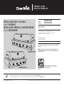 1
1
-
 2
2
-
 3
3
-
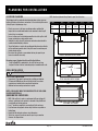 4
4
-
 5
5
-
 6
6
-
 7
7
-
 8
8
-
 9
9
-
 10
10
-
 11
11
-
 12
12
-
 13
13
-
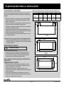 14
14
-
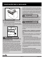 15
15
-
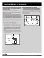 16
16
-
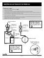 17
17
-
 18
18
-
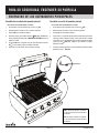 19
19
-
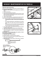 20
20
-
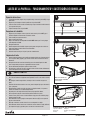 21
21
-
 22
22
-
 23
23
-
 24
24
-
 25
25
-
 26
26
-
 27
27
-
 28
28
-
 29
29
-
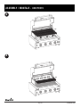 30
30
-
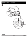 31
31
-
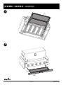 32
32
-
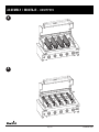 33
33
-
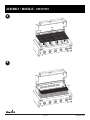 34
34
-
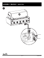 35
35
-
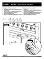 36
36
-
 37
37
-
 38
38
-
 39
39
-
 40
40
-
 41
41
-
 42
42
-
 43
43
-
 44
44


Char-Broil 463277519 Guía de instalación
- Categoría
- Barbacoas
- Tipo
- Guía de instalación
- Este manual también es adecuado para
en otros idiomas
Artículos relacionados
Otros documentos
-
Saber Compact K00SB1814 Assembly & Product Manual
-
Saber Compact R50SB0412 Grill Assembly & Product Manual
-
-
Intermatic PX50 Instrucciones de operación
-
Charbroil 463376319 El manual del propietario
-
LANDMANN 42304NG El manual del propietario
-
LANDMANN 42301 El manual del propietario
-
LANDMANN 42302 El manual del propietario