Owner's Manual
Manual del Propietario
®
THROUGH-THE-WALLAIRCONDITIONER
ACONDICIONADODEAIREA TRAVESDEPARED
Model, Modelo 580.75119
Sears, Roebuck and Co., Hoffman Estates, IL 60179 U.S.A.
www.sears.com

TABLE OF CONTENTS ........................2
WARRANTY ..............................................2
SAFETY .....................................................3
Important Safety Instructions ...................... 3
ELECTRICAL REQUIREMENTS .......4
INSTALLATION ........................................5
Installation Requirements ......................... 5
Installation ................................................ 6
Procedure A ............................................. 7
Procedure B ............................................. 8
Procedure C........................................... 10
OPERATION ...........................................12
How and Why ......................................... 12
Normal Sounds ...................................... 12
Capacity and Running Time ................... 12
Features ................................................. 13
Using the Air Conditioner ....................... 13
Air Conditioner Features ........................ 14
MAINTENANCE .....................................16
Air Filter Cleaning ................................... 16
Air Conditioner Cleaning ........................ 16
How to Remove the Front Grille ............. 16
How to Replace the Front Grille ............. 16
TROUBLESHOOTING .........................17
Before Calling for Service ...................... 17
ESPANOL ................................................18
MASTER PROTECTION
AGREEMENTS ......................................35
SERVICE NUMBERS ............ Back Cover
FULL ONE YEAR WARRANTY ON
THROUGH-THE-WALL AIR CONDITIONER
For one year from the date of purchase, when this
air conditioner is operated and maintained for
normal room cooling according to instructions in this
owner's manual, Sears will repair this air
conditioner, free of charge, if defective in material or
workmanship.
WARRANTY SERVICE IS AVAILABLE BY
CONTACTING SEARS SERVICE AT 1-800-4-
MY-HOME ®.
This warranty applies only while this product is in
use in the United States.
This warranty gives you specific legal rights, and
you may also have other rights which vary from
state to state.
Sears, Roebuck and Co., D/817WA,
Hoffman Estates, IL 60179 U.S.A.
-2-

IMPORTANT SAFETY INSTRUCTIONS
The safety instructions below will tell you how to use your room air conditioner to avoid harm to yourself or
damage to your ROOM AIR CONDITIONER.
V!_W:_;t_II_[_FOR YOUR SAFETY
Do not store or use gasoline or other flammable
vapors and liquids in the vicinity of this or any other
appliance. Read product labels for flammability and
other warnings.
PREVENT ACCIDENTS
To reduce the risk of fire, electrical shock, or injury
to persons when using your air conditioner, follow
basic precautions, including the following:
• Be sure the electrical service is adequate for the
model you have chosen.
• If the air conditioner is to be installed in a window,
you will probably want to clean both sides of the
glass first. If the window is a triple-track type with a
screen panel included, you may want to remove
the screen completely before installation.
• Be sure the air conditioner has been securely and
correctly installed according to the instructions in
this manual.
Save this manual and installation instructions for
possible future use in removing or reinstalling this
unit.
• Use gloves when handling the air conditioner.
Be careful to avoid cuts from sharp metal fins on
front and rear coils.
V!_W,.1;i_ll_[dELECTRICAL INFORMATION
The complete electrical rating of your new room air
conditioner is stated on the serial plate. Refer to the
rating when checking the electrical requirements.
• Be sure the air conditioner is properly grounded.
To minimize shock and fire hazards, proper
grounding is important. The power cord is
equipped with a three-prong grounding plug for
protection against shock hazards.
• Your air conditioner must be plugged into a
properly grounded wall receptacle. If the wall
receptacle you intend to use is not adequately
grounded or protected by a time delay fuse or
circuit breaker, have a qualified electrician install
the proper receptacle.
• Do not run air conditioner with packing sheet of
the back of the sleeve, and packing corner and
blue tape of the air conditioner. This could result in
mechanical damage within the air conditioner.
• Do not use an extension cord or an adapter
plug.
_ Avoid fire hazard or electric shock.
Do not use an extension cord or an adapter plug.
Do not remove any prong from the power cord.
Grounding type
wall receptacle
Do not under any
circumstances cut,
remove, or bypass
the grounding prong
from this plug.
Power supply cord
with 3-prong
grounding plug
ENERGY SAVING IDEAS
• The capacity of the room air conditioner must fit
the room size for efficient and satisfactory
operation.
• Install the room air conditioner on the shady side
of your home. A window that faces north is best
because it is shaded most of the day.
• Do not block air flow inside with blinds, curtains, or
furniture; or outside with shrubs, enclosures, or
other buildings.
• Close the floor and wall registers and the fireplace
damper so cool air does not escape up the
chimney and into the duct work.
• Keep blinds and drapes in other windows closed
during the sunniest part of the day.
• Clean the air filter as recommended in the
MAINTENANCE section of this manual.
• Proper insulation and weather stripping in your
home will help keep warm air out and cool air in.
• External house shading with trees, plants or
awnings will help reduce the air conditioner's work
load.
• Operate heat producing appliances such as
ranges, washers, dryers, and dishwashers during
the coolest part of the day.
-3-

OBSERVEALLLOCALCODESAND
ORDINANCES.
DONOT,UNDERANYCIRCUMSTANCES,
REMOVETHEPOWERSUPPLYCORD
GROUNDPRONG.
ELECTRICALGROUNDISREQUIREDON
THISAPPLIANCE.
208/230-volt60Hzand115-volt60Hz,AC
only,15Afusedandproperlygrounded
electrical supply is required. A time delay fuse
or time delay circuit breaker is recommended.
Use a dedicated circuit, serving only this
appliance.
DO NOT USE AN EXTENSION CORD.
RECOMMENDED GROUNDING METHOD
For your personal safety, this appliance must
be grounded. This appliance has a power
supply cord with a 3-prong grounding plug. To
minimize possible shock hazard, the cord must
be plugged into a mating grounding type wall
receptacle and grounded in accordance with
the National Electrical Code (ANSt/NFPA 70)
latest edition and all local codes and
ordinances. If a mating wall receptacle is not
available, it is the personal responsibility and
obligation of the customer to have a properly
grounded 3-prong wall receptacle installed by a
qualified electrician.
115V~ 230V~
Power cord may include a current interrupter
device. A test and reset button is provided on the
plug case. The device should be tested on a
periodic basis by first pressing the TEST button
and then the RESET button. If the TEST button
does not trip or if the RESET button will not stay
engaged, discontinue use of the air conditioner and
contact a qualified service technician.
NOTE:The shape may be different according to its model.
Use Wall Receptacle Power Supply
_) tandard 125V,
3-wire grounding
receptacle rated
15A, 125V AC
Standard 250V,
3-wire grounding
receptacle rated
15A,250V AC
Standard 250V,
3-wire grounding
receptacle rated
2OA,250V AC
Use t5 AMP. time
delayfuse or 15AMP.
circuit breaker.
Use 20AMP. time
delay fuse or 20AMP.
circuit breaker.
AWARNING
Electrical Shock Hazard
Plug into a grounded 3 prong outlet.
Do not remove ground prong.
Do not use an adapter.
Do not use an extension cord.
Failure to follow these instructions can result in
death, fire, or electrical shock.
3-prong
grounding
plug
Reset-
Test
Ground
prong
supply
cord
(208/230-volt 60 Hz)
--3-prong
grounding
type wall
receptacle
(115-volt 60 Hz)
-4-

INSTALLATION REQUIREMENTS
If you use an existing wall sleeve, you should
measure its dimensions.
Install the new air conditioner according to these
installation instructions to achieve the best
performance. All wall sleeves used to mount the
new air conditioner must be in good structural
condition and have a rear grille to securely attach
the new air conditioner. (FIG. 1)
With the Kenmore folding sleeve, you can
maintain the best performance of the new air
conditioner.
19-2//32"
(499 ram) 24-2q32"
(626 ram)
6ram)
Air Conditioner
ram)
FIG. !
ELECTRICAL SERVICE
Check your available electrical service. The power
supply available must be the same as that shown
on the unit nameplate (found on left side of cabinet).
All models are equipped with a 3-prong service plug
to provide proper service and safe positive
grounding. Do not change plug in any way. Do not
use an adapter plug. If your present wall outlet does
not match your plug, call a qualified electrician to
make the necessary corrections. SAVE CARTON
for storage and this OWNER'S MANUAL for future
reference. The carton is the best way to store unit
during winter or when not in use.
INSTALLATION HARDWARE
2 Size options
2 Size options
ITEM NAME OF PARTS Q'TY
_'1_ i PLASTIC GRILLE 1
i HORIZONTAL INSULATION STRIPS 2
i AROUND INSULATION STRIPS 2
SUPPORT BLOCK 2
::BAFFLE 1
@ i TRIM FRAME 2
i SHIM 2
{8_ i PLASTIC NUTS AND WASHER SCREWS 4
_B_ GRILLE REAR I
To avoid risk of personal injury, property damage,
or product damage due to the weight of this
device and sharp edges that may be exposed:
• Air conditioners covered in this manual pose an
excessiveweight hazard. Two or more people
are needed to move and install the unit.
To prevent injury or strain, use proper lifting and
carrying techniques when moving unit.
• Carefully inspectlocation where air conditioner
will be installed. Be sure itwill support the weight
ofthe unitover an extended periodof time.
• Handle air conditioner with care. Wear
protective gloves whenever lifting or carrying the
unit. AVOID the sharp metal fins offront and
rear coils.
• Make sure air conditioner does not fall during
installation.
REQUIRED TOOLS:
•Tight Fitting gloves
•Standard screwdriver
•Phillips screwdriver
• Pliers
•Sharp knife
• 3/8-inch open end
wrench or adjustable
wrench
• 1/4-inch hex socket
and ratchet
• Tape measure
• Electric drill
• 1/4-inch drill bit
-5-

INSTALLATION
We strongly recommend the removal of the
oldwall sleeve and the installationof a new
Kenmore folding Wall Sleeve,
If you decide to keep the existing wall sleeve,
you haveto redirect the louvers at the back of the
wall sleeve illustration. The use of pliers is
recommended. If you DO NOT redirect,you run
the risk of poor performance or product failure.
This is not covered under the terms of the
Kenmorewarranty.
• Pick a location which will allow the conditioned air to
blow into the area you want. Good installation with
special attention to the proper position of the unit will
lessen the chance that service will be needed.
NOTE: All wall sleeves used to mount the new Air
Conditioner must be in sound structural condition
and have a rear grille that securely attaches to
sleeve, or rear flange that serves as a stop for the
Air Conditioner,
_-'_ Remove old air conditioner from existing wall
sleeve.
_1 Clean the interior of an existing sleeve.
(Do not disturb seals.)
D Wall sleeve must be securely fastened in wall
before installing the air conditioner. Use the
nails or screws through sleeve into wall, if
needed. Repaint sleeve if needed.
_4J Prepare the wall sleeve for installation of the
unit. If you plan to use your existing wall sleeve,
and it is not Kenmore, use procedure B or C
below.
ITEMS IN INSTALLATION HARDWARE
You may not need all parts in the kit. Discard unused
_arts
Plastic grille
Horizontal insulation Strips
Around Insulation Strips
Support Block
Baffle
Shim
Trim Frame
Washer Screw
Nuts(Plastic)
Grille Rear
ITEM (inches)
263/4 x 161/2
13/8 x 5/8 x 273/18
13/8 x 13/8 x 273/18
13/8 x 3/4 x 611/2
13/8 x 13/8 x 611/2
13/4 x 13/8 x 45/18
14 x 41/2 x 1/8
13x 1 x3/4
Qty.
1
1
1
1
1
2
1
2
2
4
4
1
HOW TO INSTALL
D Identify the existing wall sleeve before installing
the unit from the listed below.
Brand Wall Sleeve Dimensions (inches)
White-Westinghouse
Frigidaire
Carrier (52F series)
General Electric
/Hotpoint
Width
25-1/2
26
Whirlpool 25-7/8
Fedders/Emerson 27
Sears/Kenmore 25-7/8
Emerson/Fedders 26-3/4
Carrier (51S Series) 25-3/4
Friedrich 27
Height Depth
15-1/4 16, 17-1/2
or 22
15-5/8 16-7/8
17-1/8
16-1/2
or 23
16-3/4 16-3/4
or 19-3/4
15-17/32 16-23/32
15-3/4 15
16-7/8 18-5/8
16-3/4 16-3/4
Procedure Brand Depth(inches)
A Sears/Kenmore 16-23/32
White-Westinghouse
Frigidaire Carrier 16, 17-1/2
or 22
(52F series)
B General Electric
16-7/8
/Hotpoint
Whirlpool 17-1/8 or 23
Carrier (51S series) 18-5/8
16-3/4
Fedders/Emerson
or 19-3/4
C
Emerson/Fedders 15
Friedrich 16-3/4
Q Install new unit into wall sleeve.
CAUTION: When installation is completed,
replacement unit MUST have a rearward slope as
shown. To achieve 1/4" slope, remove the backing
from the 13" shim strips and attach them as shown
below in Fig. 2. Place the higher portion of shim to
the front of the rib on base of wall sleeve.
I 'r highI [
SHIM PLACEMENT
JI3/4 " High
UNiT Wall Sleeve
UNIT INSTALLATION
FIG. 2
-6-

PROCEDURE A
O If are using the new sleeve (optionally
you
supplied with your unit),skip to step 3.
Otherwise, install the plastic grille from the kit.
Cut the plastic grille to 25-1/2" wide and 15-1/4"
high. Place the plastic grille to the inside of the
wall sleeve at the rear flange.
FIG. 3
_"_ Fasten the 4 washer screws to secure the grille
to the wall sleeve. If you need plastic nuts to
mount plastic grille to the inside of the wall
sleeve, there are plastic nuts in the installation
kit. The nuts are installed from the inside of the
sleeve and are pressed into the square holes of
the rear flanges.
FIG. 4
_J Remove the backing from the Horizontal
Insulation strip 13/8 x 3/8x 273/16 and attach that
to the inside bottom of the sleeve as shown
below. Remove the backing from the Around
Insulation strip 13/8 X 3/4X 611/2 and attach that
to the inside front of the sleeve as shown
below.
FIG. 5
D Remove the metal rear grille and replace it with
the plastic rear grille to improve unit energy
efficiency. The plastic grille reduces the amount of
hot air discharge that recirculates through the unit.
PIastic rear grille
Steel rear
FIG. 6
_JTo assemble trim, snap the tab of each piece
into the slot of the other piece as shown below.
Slide trim over the front of the air conditioner
until trim is flush with sleeve as shown below.
Trim (2 ea)
Wall
FIG. 7
•Air conditioners covered in this manual pose
an excessive weight hazard. Two or more
people are needed to move and install the unit.
To prevent injury or strain, use proper lifting
and carrying techniques when moving unit.
•When handling the air conditioner, be careful
to avoid cuts from sharp metal fins on front and
rear coils.
• Make sure air conditioner does not fall during
removal.
, If unitdoesnotoperateafterinstallationcheck,to be
surethecircuitinterrupterhasnotbeentripped.Refer
totheTroubleshootingguideforresetprocedure.
-7-

PROCEDURE B
H Redirect the louvers at the back of the wall
sleeve to 60 ° angle as shown in the FIG 8. The
use of pliers is recommended.
Rear Louvers
(Top View)
7 51/6"
FIG. 8
I_lf the wall sleeve already has a rear grille, skip
to step 4. If the wall sleeve does not have a rear
grille or Iouvered panel, install the plastic grille
from the kit. Cut the plastic grille to 25-1/2" wide
and 15-1/4" high. Place the plastic grille to the
inside of the wall sleeve at the rear flange.
Place the plastic grille
FIG. 9
I[_ Fasten the 4 washer screws to secure the grille
to the wall sleeve. If you need plastic nuts to
mount plastic grille to the inside of the wall
sleeve, there are plastic nuts in the installation
kit. The nuts are installed from the inside of the
sleeve and are pressed into the square holes of
the rear flanges.
or
Fasten the screws
FIG. 10
_J Remove the backing from the Horizontal
Insulation strip 13/8x 5/8x 273/16 and attach that
to the inside bottom of the sleeve as shown
below. Remove the backing from the Around
insulation strip 13/8 x 3/4 x 61 I/2 and attach that to
the inside front of the sleeve as shown below.
FIG. 11
1_4J Remove the metal rear grille and replace it with
the plastic rear grille to improve unit energy
efficiency. The plastic grille reduces the amount of
hot air discharge that recirculates through the unit.
Plastic rear grille
Steel rear grille
FIG. 12
ir_lf the depth of your existing wall sleeve is less
than or equal to 18", skip to step 7. Otherwise,
cut the baffles and the support blocks according
to length "A" in the table below.
Depth"D"oftheexisting
wallsleeve(inches)
18 <D _<18-5/8
18-5/8<D_<19-3/4
19-3/4<D _<22
Length"A"
(inches)
3/4
1-3/4
4
_ upport
Block
• ._[_ Baffle
_J FIG. 13
-8-

PROCEDURE B
W Remove the backing from the support blocks
and attach them to the inside of the wall sleeve
as shown FIG 14. Slide the baffle into slots of
the support blocks.
Wall
Sleeve
D Install the new unit into the wall sleeve.
I_1 Assemble trim as described in Step 6,
Procedure A.
Block
FIG. 14
. Airconditionerscoveredinthismanualposean
excessiveweighthazard.Twoor morepeopleare
neededtomoveandinstalltheunit.
Topreventinjuryor strain,useproperliftingand
carryingtechniqueswhenmovingunit.
. Whenhandlingtheairconditioner,becarefultoavoid
cutsfromsharpmetalfinsonfrontandrearcoils.
•Makesureairconditionerdoesnotfallduring
removal.
. If unitdoesnotoperateafterinstallationcheck,to be
surethecircuitinterrupterhasnotbeentripped.Refer
totheTroubleshootingguideforresetprocedure.
-9-

PROCEDURE C
H Redirect the louvers at the back of the wall
sleeve to 60 ° angle as shown in the FIG 15.
The use of pliers is recommended.
7 13,/6 **
002 &to°
Rear Louvers
(Top View)
FIG. 15
I_lf the wall sleeve already has a rear grille, skip
to step 4. If the wall sleeve does not have a rear
grille or Iouvered panel, install the plastic grille
from the kit. Cut the plastic grille to 26-1/2" wide
and 15-1t2" high. Place the plastic grille to the
inside of the wall sleeve at the rear flange.
Place the plastic grille
FIG. 16
I[_ Fasten the 4 washer screws to secure the grille
to the wall sleeve. If you need plastic nuts to
mount plastic grille to the inside of the wall
sleeve, there are plastic nuts in the installation
kit. The nuts are installed from the inside of the
sleeve and are pressed into the square holes of
the rear flanges.
or
Fasten the screws FIG. 17
_J Remove the backing from the Horizontal
insulation strip 13/8 x 13/8 x 273/16 and attach that
to the inside bottom of the sleeve as shown
below. Remove the backing from the Around
insulation strip 13/8 x 13/8 x 611/2 and attach that
to the inside front of the sleeve as shown below.
FIG. 18
El
If the depth of your existing sleeve is less than
or equal to 18", skip to step 7. Otherwise, cut
the baffles and the support blocks according to
Length "A" in the table below.
Depth"D"oftheexisting
wailsleeve(inches)
18 <D_<18-%
18-5/8<D <19-3/4
19-3/4<D <_22
Length"A"
(inches)
3/4
1-3/4
4
_ upport
Block
k_ Baffle
FIG. 19
r_l Remove the backing from the support blocks
and attach them to the inside of the wall sleeve
as shown FIG 20. Slide the baffle into slots of
the support blocks
Wall
7 13'/6")
Sleeve
Block
"_. FIG. 20
-10-

PROCEDURE C
[H'.,_I]II[e] _1
lil
To achieve rearward slope for unit draining,
remove the backing from the 13" shim strips
and attach them as shown below in Fig. 22.
The higher portion of shim is to be placed in
front of the rib on the base of wall sleeve.
h,0h_ r-
l High
FIG. 21
FIG. 22
_J_ Remove the metal and it with
rear
grille replace
the plastic rear grille to improve unit energy
efficiency. The plastic grille reduces the
amount of hot air discharge that recirculates
through the unit.
• Airconditionerscoveredin thismanualposean
excessiveweighthazard.Twoor morepeopleare
neededto moveandinstalltheunit.
Topreventinjuryorstrain,useproperliftingand
carryingtechniqueswhenmovingunit.
°Whenhandlingtheairconditioner,becarefultoavoid
cutsfromsharpmetalfinsonfrontandrearcoils.
, Makesureair conditionerdoesnotfallduring
removal.
• Ifunitdoesnotoperateafterinstallationcheck,tobe
surethecircuitinterrupterhasnotbeentripped.Refer
totheTroubleshootingguideforresetprocedure.
Plastic rear grille
Steel rear
_'_ Install the new unit into the wall sleeve
_1'_ Assemble trim as described in Step 6,
Procedure A.
FIG. 23
-11-

HOW AND WHY
Your room air conditioner provides the following
functions to make hot weather living more
comfortable:
• Cools and circulates room air.
• Lowers humidity by removing excess moisture.
• Filters out summertime dust, dirt, and some
airborne impurities.
The air conditioner performs these functions by
drawing room air through a filter which traps dust
and dirt particles. The air then passes over a
cooling coil which refrigerates the air and removes
excess moisture. The same air is then returned to
the room- cooler, drier, and cleaner. Moisture
removed from the room air is carried to the outside
and evaporated.
Your air conditioner is designed to be easy to
operate and to provide plenty of cooling power.
NORMAL SOUNDS FIG.24
Aside from the regular fan motor and compressor
sounds coming from your air conditioner, you will
once in a while hear a pinging sound. This is the
result of moisture being picked up from the air in the
room and thrown against the air conditioner's fan.
This is normal and should not be cause for concern.
Also, do not be alarmed if you hear a slight hissing or
gurgling sound coming from your air conditioner after
it is off. These are normal coolant noises.
CAPACITY AND RUNNING TIME
Proper unit size is important in deciding the desired
comfort for the area you want to cool. The proper
size is determined by the number of square feet in
the area to be cooled.
Whenever the heat or humidity load is above normal
the air conditioner must run longer and more often
to keep the desired temperature you have selected.
Under heavy heat load conditions the air conditioner
may need to run constantly to keep the temperature
you want.
At times using the MED FAN setting to circulate the
room air may make it comfortable even though you
do not have the air conditioner set to cool the air.
This will decrease your cost of use.
Unit Vibration
The unit may vibrate
and make noise
because of poor wall
or window
construction.
Fan
You may hear air
movement from the
fan.
Compressor
The modern high
efficiency compressor
may have a high pitched
hum or pulsating noise
that cycles on and off.
Condenser
You may hear
droplets of water
hitting the condenser,
causing a pinging or
clicking sound.
FIG. 24
WATER DRAIN VALVE
When the outside temperature drops below 58°F
and the unit is set for heating, a drain valve opens
up to release water from the base pan. This is
normal and prevents water from freezing in the base
pan and interfering with the outdoor fan.
-12-

FEATURES
THE UNIT
1 5 7 3 6 2 8 4 FIG.25
1. CABINET
2. HORIZONTAL AIR DEFLECTOR
(Vertical Louver)
3. VERTICAL AIR DEFLECTOR
(Horizontal Louver)
4. AIR DISCHARGE
5. FRONT GRILLE
6. INLET GRILLE (Air intake)
7. AIR FILTER
8. VENT CONTROL
USING THE AIR CONDITIONER
_To reduce the risk of fire, electric
shock, or injury to persons, read the important
SAFETY instructions section before operating this
appliance.
To begin operating the air conditioner after
installation, follow these steps:
1. Plug in the air conditioner. (To prevent electrical
hazards, do not use an extension cord or an
adapter plug.)
2. Set the TEMP control to the coolest setting.
3. Set the MODE control at the highest COOL level.
4. Adjust the louvers for comfortable air flow.
5. Once the room has cooled, adjust the TEMP and
MODE control to the setting you find most
comfortable.
NOTE : If the air conditioner is turned off, wait 3
minutes before restarting. This allows pressure
inside the compressor to equalize. Failure to wait 3
minutes before restarting may cause inefficient
operation.
If you move the TEMP control to a warmer, then
immediately back to a cooler setting, the unit will
shut off. Wait 3 minutes before restarting.
Refer to the AIR CONDITIONER FEATURES
section for other settings.
VENT CONTROL
The Vent Control allows the air conditioner to either
recirculate inside air (CLOSE) or exhaust air to the
outside (OPEN). (FIG. 26)
• The CLOSE position is used when maximum
cooling is desired. It may also be used for air
recirculation without cooling when the air
conditioner is set in the FAN position.
• The OPEN position removes stale air from the
room and exhausts it to the outside. Fresh air is
drawn into the room through your home's normal
air passages.
• The OPEN or CLOSE position can be used with
any fan selection.
PULL OPEN / PUSH CLOSE
FIG. 26
-13-

CONTROLS
MODE
OFF
0
HEAT COOL
TEMP
OFF
FAN ONLY
LOW COOL
HIGH COOL
LOW HEAT
HIGH HEAT
: Turns air conditioner off.
: Fan operationwithout cooling or heating.
: Cooling with low fan speed operation.
: Cooling with high fan speed operation.
: Heating with low fan speed operation.
: Heating with high fan speed operation.
Turnthe TemperatureKnob to thedesired setting.
The centralposition isa normal settingfor averageconditions.
You can changethis setting, if necessary,in accordancewith your
temperaturepreference.
Thethermostatautomaticallycontrols coolingor heating, butthe fan
runscontinuously wheneverthe air conditioner is in operation.
If the room istoo warm,turn the thermostatcontrolclockwise.
If the room istoo cool, turnthe thermostatcontrol counterclockwise.
Thecompressor willturn on and offto keepthe roomat the set temperature.
Inthe heatingoperation, the electricheaterwill turn on and off to keepthe roomat theset temperature.
When the air conditioner has been operated in the I
cooling or heating mode and isturned off or set to|
the fan position,wait at least 3 minutesbefore
resettingto the coolingoperation again. J
A slight burning odor may come from the
unit when first switching to HEAT after the
cooling season is over. This odor, caused
by fine dust particles on the heater, will
disappear quickly. This is normal operation.
-14-

HORIZONTAL AIR-DIRECTION
ADJUSTMENT
• The horizontal air direction is adjusted by moving
vertical louver.
• The vertical louver control levers are located in the
right and left side of the air discharge.
FIG. 27
VERTICAL AIR-DIRECTION ADJUSTMENT
• The vertical air direction is adjusted by moving the
horizontal louvers.
FIG. 28
-15-

AIR FILTER CLEANING
The Air Filter will become dirty as it removes dust
from the inside air. It should be washed at least
every 2 weeks. If the Air Filter remains full of dust,
the air flow will decrease and the cooling capacity
will be reduced, possibly damaging the unit.
• Pull the inlet grille forward and pull out the air filter.
(FIG. 29)
• Wash the Air Filter under the faucet with warm
water. Be sure to shake off all the water before
replacing the filter. (FIG. 30)
FIG. 29 FIG. 30
AIR CONDITIONER CLEANING
Clean the front grille and inlet grille by wiping with a
cloth dampened in a mild detergent solution.
The cabinet may be washed with mild soap or
detergent and lukewarm water, then polished with
liquid appliance wax.
To ensure continued peak efficiency, the condenser
coils (outdoor side of the unit) should be checked
periodically and cleaned if they become clogged
with soot or dirt from the atmosphere. Brush or
vacuum exterior coils to remove debris from fins.
FIG. 31
HOW TO REMOVE THE FRONT
GRILLE
• Open the inlet grille.
• Remove the screw securing the Front Grille.
• Push the grille up from the bottom and pull the top
of the grille away from the case to lift the top tabs
out of their slots.
I
FIG. 32
HOW TO REPLACE THE
FRONT GRILLE
Attach the front grille to the cabinet by inserting the
tabs on the grille into the slots on the front of the
cabinet. Push the grille in until it snaps into place.
FIG. 33
-16-

BEFORE CALLING FOR SERVICE
Check the following list to be sure a service call is really necessary. A quick reference to this manual may
help you avoid an unneeded service call.
THE AIR CONDITIONER WILL NOT OPERATE
Check if...
The CurrentinterrupterDeviceistripped,
Walt plug disconnected.
House fuse blown or circuit breaker tripped.
Power is OFF.
Unit was turned off and then on too quickly.
TEMP Control set warmer than room temperature.
Then...
Press the RESET button located on the power cord plug.
If the RESET button will not stay engaged, discontinue use of the
air conditioner and contact a qualified service technician.
Push plug firmly into walt outlet.
Replace fuse with time delay type or resetcircuit breaker.
Push the power button.
Set unit off and wait 3 minutes before restarting.
Turn TEMP Control clockwise to a cooler setting.
AIR FROM UNIT DOES NOT FEEL COLD ENOUGH.
Check if... Then...
FAN SPEED set at LOW. Push FAN SPEED button to set at HI.
TEMP Control set too warm. Set TEMP Control to a lower temperature.
Room temperature below 70°F (21°C). Cooling may not occur until room temperature rises above 70°F (21°C).
Temperature sensing tube touching evaporator coil, Straighten tube away from evaporator coil.
located behind front grille.
THE AIR CONDITIONERCOOLING, BUT ROOM18TOO WARM-ICE FORMINGON COOLING COIL BEHIND INLET GRILLE.
Check if... Then...
Outdoor temperature below 70°F (21°C). To defrost the coil, set the MODE to FAN, FAN speed to High.
Air filter may be dirty. Clean air filter. Refer to Maintenance section ofowner's manual.
To defrostthe coil,setthe MODE to Coot, Fan speed to high, and the
TEMP Control set too low. Temp control to a higher temperature.
THEAIR CONDITIONERCOOLING,BUT ROOM18TOO WARM
Check if... Then...
Dirty airfilter- air restricted. Clean air filter. Refer to Maintenance section ofowner's manual.
TEMP Control set too warm. Set TEMP Control to a lower temperature.
Front of unit is blocked by drapes, blinds, furniture, etc. Clear blockage in front of unit.
Air distribution is restricted.
Doors,windows, registers, etc. open. Cold air escapes. Close doors, windows, registers, etc.
Unit recently turned on in hot room. Allowadditionaltimeto removestoredheatfromwalls,ceiling,floor,andfurniture.
THE AIR CONDITIONER TURNS ON AND OFF RAPIDLY.
Check if... Then...
[ Outside temperature is extremely hot. I Set FAN SPEED on HI to minimize thecooling load. J
NOISE WHEN UNIT IS COOLING.
Check if... Then...
[ Sound offanhittingwater-from the moistureremova,system.[ This isnorma, when hur_s higt_ Close doors, windows, and registers.J
/ Window vibration - poor installation. / Refer to installation instructions or check with installer. /
WATER DRIPPING INSIDE ROOM WHEN UNIT IS COOLING.
Check if... Then...
The airconditioner is improperly installed. Tiltinstallationair conditionerinstructionsslightlyor tocheckthe outsidewith installer,to allow water drainage. Refer to
WATER DRIPPING OUTSIDE WHEN UNIT IS COOLING.
Check if... Then...
The unit is removing large quantities of moisture This is normal during excessively humid days.
from humid room.
-17-

INDICE ......................................................18
GARANTiA ..............................................18
SEGURIDAD ...........................................19
Instrucciones importantes de seguridad ---19
REQUlSlTOS ELI_CTRICOS .............2o
INSTALAClON ........................................21
Requisitos de instalaci6n ....................... 21
Instalaci6n .............................................. 22
Procedimiento A..................................... 23
Procedimiento B..................................... 24
Procedimiento C..................................... 26
FUNClONAMIENTO .............................28
C6mo y por que ...................................... 28
Sonidos normales .................................. 28
Capacidad y tiempo de funcionamiento----28
Caractedsticas ....................................... 29
Uso del aparato de aire acondicionado .....29
Caractedsticas del aparato de aire
acondicionado ........................................ 30
MANTENIMIENTO ................................32
Limpieza del filtro de aire ....................... 32
Limpieza del aparato de aire
acondicionado ........................................ 32
Como extraer la rejilla frontal ................. 32
C6mo volver a colocar la rejilla frontal ...32
RESOLUClON DE PROBLEMAS----33
Antes de Ilamar al servicio tecnico ......... 33
ACUERDOS DE PROTECClON
ESPEClALIZADA ..................................35
NUMEROS DE SERVIClO
TI_CNICO .................................. Contraportada
GARANTiACOMPLETADE UNANO DEL
APARATO DEAIREACONDICIONADODE
PARED
Durante unaSo, a contar a partir de la fecha de compra, cuando
este aparato de aire acondicionado funoione para el enfriamiento
normal de una habitacion y reciba mantenimiento, todo ello
segt_nlas instruociones de este Manual del propietario, Sears
reparara este aparato de aire acondicionado, de farina gratuita, si
tuviera algt:lndefecto de fabricaoion o materiales.
EL8ERVIClO DEGARANTiAPUEDE
CONTACTARSEEN EL8ERVICIO DEATENCION
AL CLIENTEDESEARSEN EL1-800-4-MY-HOME®.
Esta garantia se aplica s6to durante el uso deeste produoto en
los Estados Unidos.
Esta garantia te concede derechos legales especificos y puede
que usted tenga otros dereohos adicionates que varian segQnel
estado.
Sears,Roebuckand Co., D/817WA,Hoffman
Estates,IL 60179 EE.UU.
-18-

INSTRUCCIONES IMPORTANTES DE SEGURIDAD
Las instrucciones de seguridad que se indican abajo le dir&n como utilizar su aparato de aire acondicionado
para evitar daSos a si mismo y daSos a su APARATO DE AIRE ACONDICIONADO.
[l'!_lJl_;tl:_II_r;1PARA8U 8EGURIDAD
No aImacene ni utilice gasolina ni otros liquidos ni gases
inflamables cerca de este u otro electrodomestico. Lea
las etiquetas de los productos para conocer su
inflamabiIidad y otras advertencias.
EVITAR ACCIDENTES
Para reducir el riesgo de incendio, eIectrocucion o heridas a
personas at utilizar su aparato de aire acondicionado, siga
las precauciones b&sicas, incIuyendo las siguientes:
• Aseg0rese de que et servicio electrico es adecuado para el
modelo que ha escogido.
• Si el aire acondicionado va a instatarse en una ventana,
seria conveniente que Iimpiara primero ambos lados deI
cristal. Si la ventana tiene tres guias de desIizamiento, con
un panel pantaIIa incIuido, puede que desee extraer
compIetamente Ia pantalla antes de Ia instaIacion.
• Aseg0rese de que el aparato de aire acondicionado se ha
instalado de modo seguro y correcto segOn Ias
instrucciones en este Manual. Guarde este manual y las
instrucciones de instalaci6n para su posible uso futuro para
extraer o volver a instaIar esta unidad.
• Utilice guantes cuando maneje el aparato de aire
acondicionado. Preste atencion para evitar cortes de las
afitadas aIetas de metal en las bobinas frontal y posterior.
INFORMA¢ION ELI_CTRICA
El valor nominal electrico completo de su nuevo aparato de aire
acondicionado se especifica en su etiqueta identificativa.
Consulte el valor nominal al comprobar los requisitos etectricos.
• AsegQrese de que et aparato de aire acondicionado tiene
una toma de tierra adecuada. Para reducir al minimo el
riesgo de electrocucion y de incendio, es importante tener
una toma de tierra adecuada. El cable de aIimentacion esta
equipado con un enchufe de tres clavijas con toma a tierra
para proteger contra eIectrocucion.
• Su aparato de aire acondicionado debe estar enchufado a
un enchufe de pared con una toma de tierra adecuada. Si
el enchufe que quiere utitizar no tiene una toma de tierra
adecuada o no esta protegido por un fusible temporizado o
un interruptor de corriente, haga que un electricista
cuaIificado instate el enchufe apropiado.
• No haga funcionar el aparato de aire acondicionado con la
lamina de embataje en la parte posterior det aIojamiento o
con la cinta azul y las esquineras det aparato de aire
acondicionado. Esto podria tener como consecuencia la
producci6n de da_os mecanicos at aparato de aire
acondicionado.
• No utilice un cable extensor ni un enchufe adaptador.
_Eviteios de incendio de electrocucion.
peligros
O
Noutiliceuncableextensorni unenchufeadaptador.
Noquite ningunaclavija del cabledealimentaei6n.
Enchufe de
pared deI tipo
puesta
a tierra
ninguna
circunstancia corte_
desmonte o puentee el
diente de puesta atierra
de este enchufe.
Cable de aIimentaci6n
con enchufe de puesta a
tierra de tres dientes
Reponga
Prueba
IDEAS PARA AHORRAR ENERGiA
• La capacidad del aparato de aire acondicionado debe
ser adecuada al tamafio de la habitacion para un
funcionamiento eficaz y satisfactorio.
• Instale el aparato de aire acondicionado en el lado de su
hogar a la sombra. Una ventana que mira al norte es la
mejor porque se encuentra a Ia sombra la mayor parte
deI dia.
• No bloquee el flujo del aire en el interior con persianas,
cortinas o muebles, ni en el exterior con arbustos,
cercas u otros edificios.
•Cierre las aperturas en suelo y ventanas y el tiro de la
chimenea para que el aire frio no salga por Ia chimenea
ni por los conductos.
• Mantenga cerradas las persianas y cortinas de otras
ventanas durante la parte mas soleada deI dia.
• Limpie el filtro de aire segOn se recomienda en la
seccion de MANTENIMIENTO de este manual.
• El aislamiento adecuado y la preparacion de su hogar
para las condiciones atmosfericas mantendran el aire
caliente en el exterior y el aire frio en el interior.
• La existencia de sombra en el exterior de la casa con
arboles, plantas o totdos reduce la carga de trabajo deI
aparato de aire acondicionado.
• Haga funcionar los electrodomesticos que produzcan
calor, come cocinas, lavadoras, secadoras y Iavavajillas,
durante Ia parte mas fria del dia.
-19-

RESPETE TODOS LOS CODIGOS Y
REGLAMENTOS.
BAJO NINGUNA CIRCUNSTANCIA CORTE,
QUITE O EVITE EL USO DE LA CONEXION A
TIERRA DE ESTA CLAVIJA.
LA TOMA A TIERRA ES NECESARIA EN ESTE
ELECTRODOMI_STICO.
Esnecesaria una fuente de alimentaci6n electrica
de 208/230 voltios, 60 Hz y 115-voltios, 60 Hz, s61o
AC, confusible de 15 A y correctamente puesta a
tierra. Se recomienda el uso de un fusible o
interruptor de retardo. Utilice un circuito dedicado,
Onicamentepara este electrodomestico.
NO USE CABLE ELECTRICO DE EXTENSION.
MI_TODORECOMENDADODE CONEXION A
TIERRA
Por su propia seguridad este aparato debe
conectarse a tierra. Este aparato viene equipado
con un cable de alimentaci6n y una clavija de tres
terminales. Para reducir al maximoel peligro de
choque electrico, el cable debe estar conectado a
una conexi6n de pared con conexi6n a tierra, y esta
conexi6n debe hacerse de acuerdo con la Oltima
edici6n del C6digo Electrico Nacional (ANSI/NFPA
70), asi como con losc6digos y reglamentos
locales. Si no existe una conexi6n de pared
adecuada, el cliente tiene la responsabilidad y la
obligaci6n de mandar instalar, con un electricista
calificado, una conexi6n de pared adecuada de tres
terminales con conexi6n a tierra.
115V~
_=====_
230V~
Elcabledealimentaci6npuedeincluirundispositivo
interruptordecorriente.Lacarcasadeienchufecuenta
conunbot6ndepruebayotrodereinicio.Eldispositivo
debecomprobarseperi6dicamentepresionando
primeroelbot6nTESTydespuesRESET.
Sielbot6nTESTnosedesconectao sielbot6n
RESETnopermaneceactivo,suspendaelusodelaire
acondicionadoyp6ngaseencontactoconunt@nico
deserviciocualificado.
NOTA:La forma puede serdiferente segQnsu modelo.
Utiliceelenchufedelapared Consumode Energia
Standard 125V,
enchufe de 3
Lineas de
15A, 125V AC
Standard 250V,
enchufe de 3
Lineas de
15A, 250V AC
Standard 250V,
enchufe de 3
Lineas de
20A, 250V AC
Utilice unfusible de
15AMP.o un
Interrupter de 15AMP.
Utilice unfusible de
20AMP. o un
Interrupter de 20AMP.
A ADVERTENCIA
Peligro de choque electrico
Conecte en una conexi6n de pared de 3 terminales
No quite la terminal de conexi6n a tierra
No use adaptadores
No use cable electrico de extensi6n
Si no se siguen estas instrucciones, puede ocasionarse
ia muerte, un incendio o un choque electrico,
Enchufe de puesta a
tierra de 3 dientes
Cable de
alimentaci6n
--Enchufe de
pared del tipo
de puesta a
tierra de 3
dientes
Diente de
puesta a tierra
(208/230-voltios 60 Hz) (115-voltios 60 Hz)
- 20 -

REQUISITOS DE INSTALACION
Si utiliza un alojamiento de pared existente, debe tomar sus
medidas.
tnstale el nuevo aparato de aire acondicionado segOnestas
instruccionesde instalacionpara conseguir el mejor rendimiento.
Todos los alojamientos de pared utilizados para montar el nuevo
aparato de aire acondicionado deben tener su estructura en
buenas condiciones y tener una rejilla posterior para fijar con
seguridad el nuevo aparato de aire acondicionado. (FIG.l)
Con el alojamiento Kenmore, puede mantener el maximo
rendimiento de su nuevo aparato de aire acondicionado.
19-2//32"
(499 mm) 24-2q32"
(626 ram)
[3/32"
6mm)
Aparatodeaireacondicionado
ram)
FIG. !
SERVIClO ELECTRICO
Compruebe el servicio electrico disponibte. La alimentaci6n
disponible debe coincidir con taque se muestra en la etiqueta
identificativa de la unidad (que se encuentra en el lado izquierdo
del alojamiento).
Todos los modelos estan equipados con un enchufe de servicio
de 3 clavijas con unatoma detierra positiva segura. No
modifique el enchufe de ninguna manera. No utilice unenchufe
adaptador. Si sutoma de corriente en la pared no coincide con eI
enchufe, llame a un electricista cualificado para realizar los
cambios necesarios. GUARDE LA CAJA para el almacenamiento
y esta GUiA DELPROPIETARiO parafutura referencia. La caja
es la mejor manera de almacenar la unidad durante el invierno o
cuando no se utilice.
EQUIPO DE INSTALACION
ARTiOULC
Q
®
®
®
®
®
®
®
2opcionesdetama_o
2opcionesdetama_o
NOMBREDE LASPtEZAS
REJILLA DE PLASTICO
TIP.AS DE AISLAMIENTO HORIZONTAL
TIRAS DE AISLAMIENTO LATERAL
BLOQUE DE SOPORTE
DEFLECTOR
BASTIDOR DE REBORDE
CALZO PARA AJUSTE
TUERCASDEP_STIC0 YTORNILLOSDEARANDELA
PARTEPOSTERIORDE LA REJILLA
CANTIDAD
1
2
2
2
1
2
2
4
1
ParaevitarpeligrodeheridaspersonaIes,daSosalapropiedado
aIproductodebidoalpesodeesteaparatoyatosbordes
afitadosquepuedenestarexpuestos:
,Losaparatosdeaireacondicionadodetosquetrataeste
manualconstituyenunpeligrodepesoexcesivo.Senecesitan
dos0maspersonasparamovereinstalarIaunidad.Paraevitar
heridas0problemasmusculares,utiticetecnicasadecuadas
paraelevarydesplazarlaunidad.
,Revisecuidadosamentelaubicaci6ndondeseinstalaraelaparato
deaireac9ndici9nad9.AsegQresedequepuedes9portarelpeso
delaunidadduranteunperiod9detiemp9prolongad9.
,Manejeconcuidadoelaparatodeaireacondicionado.Ueve
guantesprotectoressiemprequelevante0desptacelaunidad.
EVITElasaletasafiladasdemetaidelasbobinasfrontaly
posterior.
,AsegQresedequeelaparatodeaireacondicionadonocaeal
suelodurantelainstalaci6n.
HERRAMIENTASNECESARIAS:
•Guantesajustados
•Destornilladorestandar
•DestornilladorPhillips
•Cuchilloafilado
•Cintaparamedir
oLlaveajustableodeextremo
abiertode0.96cm(3/8depulgada)
, Llavearticulada
, Llavedecabezahexagonalde
0,64cm (1/4depuigada)y
trinquete
, Taladroelectrico
, Brocadetaladrode0,64cm
(1/4depuigada)
-21 -

INSTALAClON
8erecomiendaencarecidamentelaextractiondelantiguo
alojamientodelaparedylainstalaciondeunalojamiento
plegabledelaparedKenmorenuevo.
Sidecidemantenerelalojamientodeparedexistente,tendra
queajustarladirecci6ndelarejillaenlaparteposteriordela
ilustraci6ndelalojamientodepared.Serecomiendaelusode
tenazas.SiNOajustaladirecci6n,correelriesgodeun
rendimientopobreodefallodelproducto.Estehechonoesta
cubiertobajolosterminosdelagarantiadeKENMORE.
• Sidecidemantenerelabjamientodeparedexistente,tendr&queajustarla
direcci6ndelarejiHaenlaparteposteriordela ilustraciondelalojamiento
depared.Serecomiendaelusodetenazas.SiNOajustaladirecci6n,
correelriesgodeunrendimientopobreodefalb delproducto.Estehecho
noestacubiertobajolosterminosdelagarantiadeKENMORE
ARTiCUL08ENELEQUIPODEINSTALACION
Puede que no necesite todas las partes del equipo de
instalacion. Tire las piezas que no utilice.
ARTiCULO
Rejifiadeplastico
TirasdeaislamJentohorizontal
TirasdeaislamJentolateral
Boquedesoporte
Deflector
@zoparaajuste
Bestidordereborde
Tornillodearandela
Tuercas(plastico)
Parteposteriordelarejflla
38I x254x210,03cm(263/4x16_/2)
35x1,52x69,03cm(lS/_xs/8x27386)
35x3,5x69,03cm(1s/8x IS/8x27386)
35x2,03x 153,035(1s/8x 8/x61V2)
35x3,5x 153,035(1s/8xI8/8x611/2)
889x35x10,94cm(13/4x1%x4%)
35,56x11,43x0,33(14x482x _/8)
33,02x2,54x2,03(13x I x8/4)
Cantidad
1
1
1
1
1
2
1
2
2
4
4
1
COMOINSTALARLO
D identifique el alojamiento existente en la pared antes de
instatar la unidad de la lista que se muestra a continuacion
Marca
Medidas del atojamiento de la pared
(puIgadas y centimetros)
Anchura Altura Profundidad
White-Westinghouse 64,77 38,73 40644445,55,88
Frigidaire
Carrier (Serie52F) (25-1/2) (15-1/4) (16, 17-1/2)
GeneralElectridHotpoint 66,04(26) 39,70(15-5/8)42,87(16-7/8)
43,51o58,42
Whirlpool 65,48(25-7/8',41,91(16-1/2) (17-1/8o 23)
4254o50.16
Fedders/Emerson 68,58(27) 42,54(16-3/4)[16-3/4o193/4)
Sears/Kenmore 65,73(25-7/8)39,44(15-17/32)42,46(16-23/32)
Emerson/Fedders 67,94(26-3/4) 40 (15-3/4) 38,1 (15)
Carrier (Serie51S) 65,40(25-3/4) 42,87(16-7/8)47,32(18-5/8)
Friedrich 68,58(27) 42,54(16-3/4)42,54(16-3/4)
- 22 -
NOTA: Todos los alojamientos de pared utilizados para montar
el nuevo aparato de aire acondicionado deben estar en buenas
condiciones estructurales y tener una rejilla posterior que se una
con seguridad al alojamiento oun fiance posterior que sirva de
tope al aparato de aire acondicionado,
_'_ Extraiga el antiguo aparato de aire acondicionado del
atojamiento de pared ya existente.
_!_ Limpie el interior deIalojamiento de pared ya existente.
(No toque los sellados.)
D EIatojamiento de pared debe estar bien fijado a la pared
antes de instalar el aparato de aire acondicionado. Si fuera
necesario, utilice los clavos o tornillos para fijar el
atojamiento a la pared.
- Vuelva a pintar el alojamiento si fuera necesario.
_J Prepareelalojamientodeparedparala instalaciondelaunidad.8i
piensautilizarel alojamientoyaexistente,ynoesdelamarcaKenmore,
utiflcelosprocedimientosBoCqueseexplicanacontinuaci6n.
Procedimiento Marca Profundidad
A Sears/Kenmore 42,44(16-23/32)
White-Westinghouse
40,64, 44,45 0 55,88
Frigidaire Carrier (!6, 17-1/2o 22)
(52F series)
B General Electric
42,87 (16-7/8)
/Hotpoint
Whirlpool 43,5o 58,42 (17-1/6o23)
Carrier (51S series) 47,29 (18-5/6)
Fedders/Emerson 42.54o50,16(16-3/4o19-3/4)
C Emerson/Fedders 38,1(15)
Friedrich 42,54(16-3/4)
r'_ tnstate la unidad el de la
nueva en
atojamiento pared.
PREOAUOION: AI finalizar la instalacion, la unidad de
sustitucion DEBE tener una pendiente hacia atras segOn
se ilustra. Para Iograr una pendiente de 1/4", retire el
envoltorio de las cui_as de 13" y acoplelas segOn se
muestra a continuacion en la FIG. 2. Coloque el extremo
m_ls alto de la cu5a en la parte frontal de la base dei
soporte de pared.
1"de-
a,,o;I
COLOCACION DE LA CUhlA
]_ 3/4"de alto
T
Soporte
UNIDAD de pared
INSTALAClON DE LAUNIDAD
FIG. 2

PROCEDIMIENTO A
H Si esta utilizando un nuevo soporte de pared
(incluido opcionalmente con su unidad), salte al paso
3. Si no es asi, instaIe la rejilla plastica. Corte la
rejilla plastica a 25-1/2" de ancho y 15-!/4" de alto.
Coloque la rejilla plastica en el interior del soporte de
pared en la pestafia posterior.
%_ FIG. 3
I_ Apriete los 4 tomillos de arandela para fijar la rejilla
al alojamiento de pared. Si necesita tuercas de
plastico para montar la rejilla de ptastico en el interior
del alojamiento, hay tuercas de plastico en el equipo
de instalaci6n. Las tuercas se instalan desde el
interior del alojamiento y se introducen apretandolas
en ios orificios cuadrados de ios flancos traseros.
FIG. 4
I_J Extraiga la de la tira de Aislamiento
parte posterior
horizontal de 3,5 x 0,96 x 69,06 cm (13/8x 3/5x
273h6) y fijela a la parte inferior intema del
alojamiento segOn se muestra abajo. Extraiga la
parte posterior de la tira de Aislamiento lateral de 3,5
x 1,9 x 156,21 cm (13/8x 3/4x 611/2) y fijela al interior
dei alojamiento segun se muestra abajo.
FIG. 6
1_4JlPara montar el reborde, inserte el saliente de cada
pieza en la ranura de la otra pieza segun se muestra
abajo. Deslice el reborde sobre la parte frontal del
aparato de aire acondicionado hasta que el reborde
este unido a patio con el alojamiento segOn se
muestra a continuacion.
Adorno (2ea)
Pared
FIG. 7
FIG. 5
Q Desmontela rejilla metaticaposterior sustituyala tarejiIla
Y pot
plastica posterior para rnejorarel rendirnientoenergeticode ta
unidad. La rejilla plasticareduce la cantidad dedescarga de
aire calienteque recircula a traves de la unidad.
-23-
Losaparatosdeaireacondicionadode losquetrata
estemanualconstituyenunpeligrode pesoexcesivo.
Se necesitandoso maspersonasparamovere
instalarlaunidad.Paraevitarheridaso problemas
musculares,utilicetecnicasadecuadasparaelevary
desplazarlaunidad.
AImanejarelaparatodeaireacondicionado,tenga
cuidadodeevitarcortesdelasaletasafiladasde metal
en Iasbobinasfrontalytrasera.
AsegQresedequeelaparatode aireacondicionadono
secaedurantelainstalaci6n.
Sila unidadnofuncionatrasla revisi6ndeinstalaci6n,
asegQreseclueel interruptordelcircuitonoseha
disparado.Consultelaguiade soluci6ndeaverias
paraconocerel procedlmientodereinicio.

PIROCEDIMIENTO B
O Cotoque la direccion de Ia rejilla en la parte posterior del
aIojamiento de la pared en un angulo de 60° segOn se
muestra en la FIG 8. Se recomienda el uso de tenazas.
19,84 cm(7 5_/6")
Rejitla posterior
(Vista superior)
FIG. 8
_Si el atojamiento de pared esta ya equipado con una
rejilla trasera, pase directamente al paso 4. Si et
aIojamiento de la pared no tiene una rejilla posterior ni
un panel con lamas, instale la rejitla de plastico del
equipo de instalacion. Corte la rejilIa de ptastico a unas
medidas de 64,77 cm (25-1/2) de ancho y 38,74 cm
(15-1/4) de alto. Cotoque la rejilla de plastico en el
interior del alojamiento de pared en el flanco posterior.
LI_Ij Extraiga ta parte posterior de la tirade Aislamiento
horizontal de 3,5 x 1,60x 69,06 cm (13/8x 5Isx 273/_6)y fijela
a la parte inferior interna del alojamiento seg0n se muestra
abajo. Extraiga la parte posterior de la tira de Aislamiento
lateral de 3,5 x 1,9x 156,21 (13/8x 3/4x 61% y fijela at
interior del alojamiento seg0n se muestra abajo.
FIG. 11
_41J Retire la rejiltademetal posterior sustitt_yala la rejilta
Y por
ptasticaposterior para mejorarel rendimientoenergeticode la
unidad. Larejilla ptasticareduce tacantidad de descargade
airecaliente que recircula a travesde ta unidad.
Coloque la rejilla de pl&stico
FIG. 9
_lJ Cuando el alojamiento de la pared tiene una rejilla
posterior de panei con lamas, salte al paso 3 y omita
el paso 4. Coloque la rejilla de plastico en el interior
del alojamiento de pared en el flanco posterior.
O
Apriete los tornillos
FIG. 10
FIG. 12
ir_ Cuando la profundidad del alojamiento existente es
igual o menor a 45,72 cm (18 pulgadas), pase
directamente al paso 7. En caso contrario, corte los
deflectores y los bloques de soporte segQn la
Iongitud "A" de la tabla que se muestra abajo.
Pr0fundidad"D"delal0jamient0
deparedyaexistente(pulgadas)
18 <D _<18-5/8
18-5/8<D_<19-3/4
19-3/4<D _<22
Longitud"A"
(pulgadas)
3/4
1-3/4
4
• ._[_ Deflector
A_ FIG. 13
- 24 -

PROCEDIMIENTOB
H Retire eI envoitorio de los bloques de apoyo y
acoplelos al interior del soporte de pared como
muestra Ia FIG. 14. Desiice la compuerta en las
ranuras de Ios bloques de apoyo.
....._;_i_i_ii!i!i!i!i!i!i!i!i!i!i!i!i!i!i!i!i!i!i!i!i!i!i!i!i!i!i!_
Pared
depared
deapoyo
FIG. 14
_J Instale la nueva unidad en el soporte de pared.
J[_ Ajuste ia posicion segt]n describe et paso 6,
procedimiento A.
•Losairesacondicionadostratadosenestemanual
representanunpeligroporpesoexcesivo.Son
necesariasdosomaspersonasparadesplazare
instaIarla unidad.
Paraevitarlesioneso esfuerzosexcesivos,utilicelas
tecnicasdelevantamientoydesplazamiento
apropiadasal moverlaunidad.
•Manipuleconcuidadoelaireacondicionado,tenga
cuidadodeevitarcortesdeIasaristasafiladasde
metalde lasbobinasfrontaly posterior.
. AsegQresedequeelaireacondicionadonosecaiga
aldesmontarlo.
•Sila unidadnofuncionatraslarevisi6nde
instalaci6n,asegQresequeelinterruptordelcircuito
nosehadisparado.Consultelaguiadesoluci6nde
averiasparaconocerel procedimientodereinicio.
- 25 -

PROCEDIMIENTO C
O Coloque la direcci6n de la rejilla en la parte posterior del
alojamiento de tapared en un angulo de 60° seg_n se
muestra en la FIG 15. Serecomienda el uso de tenazas.
60[_
19,84 cm(7 13/16" )
Rejitla posterior
(Vista superior)
FIG. 15
_Si el alojamiento de la pared no tiene una rejilla
posterior o un panel con lamas, instale la rejilla de
plastico del equipo de instalacion. Corte la rejilla de
pIastico a unas medidas de 67,31 cm (26-!/2) de
ancho y 39,37 cm (15-1/2) de alto.
Coloque la rejilla de plastico FIG. 16
|_!| Cuando la profundidad del alojamiento existente es
igual o menor a 45,72 cm (18 pulgadas), pase
directamente al paso 7. Corte Ios deflectores y los
bloques de soporte segOn la Iongitud "A" de ia tabla
que se muestra abajo.
o
Apriete los tornillos FIG. 17
LI_Ij Extraiga Ia parte posterior de la tira de Aislamiento
horizontal de 3,5 x 3,5 x 69,06 cm (13/8 x 1318x
273/16) y fijela a Ia parte inferior interna del alojamiento
segOn se muestra abajo. Extraiga ta parte posterior de
ta tira de Aistamiento lateral de 3,5 x 3,5 x 156,21 cm
(13/8 x 1318x 61112)y fijela aI interior frontal del
alojamiento segOn se muestra abajo.
FIG. 18
_4J Cuando la profundidad del alojamiento existente es
igual o menor a 45,72 cm (18 pulgadas), pase
directamente ai paso 7. De otra manera, corte los
desviadores y los bloques del soporte de acuerdo a
Ia Iongitud "A" en ei cuadro siguiente.
Profundidad"D"delalojamiento
deparedyaexistente(puigadas
18 <D _<18-5/8
18-5/8<D_<19-3/4
19-3/4<D _<22
Longitud"A"
(pulgadas)
3/4
1-3/4
4
k_ Deflector
FIG. 19
r_ Extraiga ta parte posterior de los btoques de soporte y
fijelos al interior del alojamiento de la pared segt_nse
muestra en la FiG 20. Deslice el deflector en tas ranuras de
los bloques de soporte.
_ de soporte
FIG. 20
- 26 -

PROCEDIMIENTO C
kd
Para Iograr una pendiente de posterior para el
drenaje de la unidad, retire el envoltorio de las
cutlas de !3" y ac6plelas segOn se muestra a
continuaci6n en la FIG. 22. Coloque el extremo
m_ls alto de la curia en la parte frontal de ia base
dei soporte de pared.
1"deTr--1 3/4"
alto __[ J_-de alto
/
FIG. 21
D Desmonte la rejilIa met_llica posterior y sustituyala
per la rejilla plastica posterior para mejorar el
rendimiento energetico de la unidad. La rejilla
pl_lstica reduce la cantidad de descarga de aire
caliente que recircula a traves de ia unidad.
°Losairesacondicionadostratadosen estemanual
representanunpeligroporpesoexcesivo.Son
necesariasdoso maspersonasparadesplazare
instalarlaunidad.
Paraevitarlesionesoesfuerzosexcesivos,utilicelas
tecnicasde levantamientoydesplazamiento
apropiadasal moverlaunidad.
°Manipuleconcuidadoel aireacondicionado,tenga
cuidadodeevitarcortesde Iasaristasafiladasde
metalde lasbobinasfrontaly posterior.
°AsegQresedequeel aireacondicionadonosecaiga
al desmontarlo.
°Si la unidadnofuncionatraslarevisi6nde
instalaci6n,asegQresequeelinterruptordeIcircuito
no sehadisparado.Consultelaguiade soluci6nde
averiasparaconocerel procedimientode reinicio.
FIG. 23
_[_J_lnstale nueva en soporte pared.
ia unidad ei de
_1 Monte el ajuste segOn Io descrito en el paso 6,
procedimiento A.
- 27 -

COMO Y PORQUE
Este aire acondicionado incluye un manual de instrucciones
para hacer mas agradables tas condiciones de habitabilidad
en estaciones calurosas.
• Refrigera y hace circular el aire de la habitacion.
• Elimina Ia humedad en exceso.
• Los filtros eliminan el polvo y la suciedad tipicas de ta
estacion, asi como las impurezas que el aire contiene.
Et aire acondicionado reatiza tas funciones anteriores al
hacer pasar el aire de la habitacion a traves de un filtro que
atrapa Ias particulas de potvo y ta suciedad. A continuacion,
el aire pasa per un serpentin de refrigeraci6n que enfria et
aire y etimina Ia humedad en exceso. El mismo aire votvera a
ta habitacion pero mas frio, mas seco y mas timpio. La
humedad que se ha etiminado det aire de la habitacion sate
aI exterior y se evapora.
Este aire acondicionado se ha disefiado para que sea faciI
de utilizar y para que proporcione la maxima capacidad de
refrigeracion.
SONIDOS NORMALES FIGI24
Ademas de los sonidos normales det compresor y del motor
del ventilador que proceden del aire acondicionado, es
posible que oiga de vez en cuando un sonido de silbidos.
Esto se debe al sonido que se produce al recoger ta
humedad det aire de la habitacion y expulsarla a traves del
ventitador deI aire acondicionado. Este sonido es normal, no
tiene porque preocuparse. Tambien es posible que se
escuche un sonido de siseo o de borboteo cuando apague el
aire acondicionado. No debe alarmarse, ya que son sonido
normales que se producen al refrigerar.
Ventilador
Vibraciones
Es posible que la unidad vibre y
emita ruidos debido a la
construcci6n deflciente de las
paredes o de las ventanas,
Esposiblequeoigaet
movimientodelventilador.
i Compresor
Es posible que el moderno
compresor de alto
rendimiento lance humo o
emita ruidos de forma
intermitente.
Condensador
Tambien es posible que
oiga gotas de agua caer
en el condensador dando
lugar a silbidos o ctics.
FIG. 24
CAPAClDAD Y TIEMPO DE
FUNClONAMIENTO
Es importante establecer tazona que desea refrigerar para
decidir en consecuencia el tamafio adecuado de la unidad.
Su tamafio depender& deI n0mero de metros cuadrados de
ta zona que desee refrigerar.
Si Ia carga de humedad o et cator es superior a Io normal, el
aire acondicionado se debera utilizar m&s tiempo y con mas
frecuencia para mantener ta temperatura establecida
deseada. Tambien es posible que el calor sea tan elevado
que tenga que utilizar et aire acondicionado constantemente
para mantener ta temperatura deseada.
Puede utilizar el valor MED FAN (ventilador media) para que
et aire de la habitaci6n circule y hacer tas condiciones de
habitabilidad mas id6neas, aunque no tenga el aire
acondicionado establecido en et mode de refrigeracion. Asi
disminuira el coste de utilizaci6n.
VALVULA DE DRENAJE DEL
AG UA
Cuando la temperatura exterior cae por debajo de los
58°F y la unidad est& ajustada para la calefaccion, una
valvula de drenaje se abre para liberar el agua del
colector de la base. Esto es normal y previene el agua
de que se congele dentro del colector de la base y que
se interfiera con el ventilador del exterior.
- 28 -

CARACTERISTICAS
LA UNIDAD
1 5 736284
1. CABINA
2. DEFLECTOR DE AIRE HORIZONTAL
(Persiana vertical)
3. DEFLECTOR DE AIRE VERTICAL
(Persiana horizontal)
4. DESCARGA DE AIRE
5. REJILLA DELANTERA
6. REJILLA DELANTERA (entrada de aire)
7. FILTRO DE AIRE
8. CONTROL DE VENTILACION
FIG. 25
UTILIZACIONDELAPARATODE
AIRE ACONDICIONADO
_Antes de utiIizar esta unidad, lea Ias
instrucciones acerca de Ia seguridad para evitar riesgos de
fuegos, sacudida electrica o da_os a personas.
Siga estos pasos para empezar a utilizar el aire
acondicionado despu_s de eu inetalaci6n:
1. Conecte el aire acondicionado. (Para evitar peligros
electricos no utilice alargaderas ni adaptadores).
2. Establezca el control de temperatura (TEMP) en el valor mas
frio.
3. Establezca el control de mode (MODE) en el nivel mas frio.
4. Ajuste las persianas para que el flujo de aire le resulte
agradable.
5. Cuando la habitacion se haya enfriado, ajuste el control de
modo y temperatura en el valor que le resulte mas
agradable.
NOTA: Si el aire acondicionado esta apagado, espere tres
minutos antes de volver a encenderlo. De esta forma se
equilibra la presion del interior del compresor. Si no espera tres
minutos antes de volverlo a encender, es posible que se
produzcan fallos de funcionamiento.
Si cambie el control de temperatura a mas templado y vuetve a
cambiar inmediatamente a un valor mas frio, la unidad de
apagara. Espere tres minutos antes de volverlo a encender.
Consulte la seccion de funciones y caracteristicas del aire
acondicionado para ver otros valores.
CONTROL DE VENTILACION
El control de ventilaci6n permite que el aire acondicionado
haga circular el aire (CLOSE) o expulse el aire al exterior
(OPEN). (FIG. 26)
• La posici6n CLOSE se utiliza cuando desee la maxima
refrigeraci6n. Tambien se utiliza para recircular el aire sin
refrigerar cuando el aire acondicionado este en la posici6n
FAN (ventilaci6n).
• En la posici6n OPEN (abierto) elimina el aire viciado de la
habitaci6n y Ioexpulsa al exterior. El aire fresco sale a la
habitaci6n a traves de los conductos de aire normales de la
casa.
• La posici6n OPEN o CLOSE se puede utilizar con cualquier
selecci6n del ventilador.
- 29 -
TIRE PARAABRIR / EMPUJE PARA CERRAR
FIG. 26

CONTROLES
MODE
HEAT
OFF
0
OFF
FAN ONLY
LOW COOL
HIGH COOL
LOW HEAT
coo[
TEMP
HIGH HEAT
: Apaga el aire acondicionado.
: Permite el funcionamiento del ventilador a baja velocidad
sin enfriar (calentar).
: Permite el enfriamiento con el funcionamiento del
ventilador a baja velocidad.
: Permite el enfriamiento con el funcionamiento del
ventilador a alta velocidad.
: Permite el calentamiento con el ventilador a baja
velocidad.
: Permite el calentamiento con el ventilador a alta velocidad.
Gire la perilladetemperaturahaciael valordeseado.La posici6ncentral
esel valornormalparalascondicionesintermedias.Si fueranecesario,
estevalorse puedecambiardependiendode latemperaturaqueprefiera.
Eltermostatocontrolaautomaticamentela refrigeraci6no lacalefacci6n,
pero elventiladorfuncionaradeforma continuasiemprequeel aire
acondicionadose encuentreenfuncionamiento.Gireel controldel
termostatoenel sentidode lasagujasdel relojsila temperaturade la
habitaci6nes demasiadoalta. Gireel controldel termostatoen el sentido
contrarioal delas agujasdel relojsi latemperaturade la habitaci6nes
demasiadofria.
El compresorse encenderay apagar¶ mantenerla temperaturaestablecidaen la habitaci6n.
En el modo de calefacci6n,el calentador electricose encender&y apagarapara mantenerla temperatura
establecidaen la habitaci6n.
Espere al menos tres minutos antes de volver a
establecer el modo de refrigeraci6n si el aire
acondicionado funcionaba en el modo de
refrigeraci6n o de calefacci6n y Ioapaga o se
establece en la posici6n de ventilaci6n.
Esposibleque salga un pocode olor a quemado
de la unidad sise cambiaa HEAT(calefacci6n)
cuandoterminela estaci6nde clima frio. Esteolor
desaparecerarapidamentey sedebe alas
pequeSasparticulasde polvoque hayen el
calefactor.Estefuncionamientoesnormal.
- 30 -

AJUSTE DE LA DIRECCION HORIZONTAL
DEL AIRE
• La direcci6nhorizontaldetaire se ajuste moviendota
persianavortical,
• Los olevadoresdotcontrol dola porsianaverticalso ubican
a la derechay a la izquierdado la doscargade airo.
FIG. 27
AJUSTE DE LA DIRECCION VERTICAL DEL AIRE
• La dirocci6nverticaldeIairo seajustemoviondotas
persianashorizontales.
FIG. 28
-31 -

LIMPIEZA DEL FILTRODE AIRE
El filtro de aire se podra ensuciar al quitar el poIvo de la parte
intema. Se debera tavar al menos cada dos semanas. Si el
filtro de aire sigue estando sucio, el flujo de aire disminuira y
ta capacidad de refrigeraciSn se reducira produciendo daSos
en ta unidad.
• Empuje Ia rejilla de entrada hacia detante y saque et fiItro
de aire. (FIG. 29)
• Lave el fiItro de aire bajo et grifo con agua tempIada.
AsegQrese de sacudir toda el agua antes de volver a
colocar el fiItro. (FIG. 30)
FIG. 29 FIG. 30
LIMPIEZA DELAPARATODE AIRE
ACONDIClONADO
Limpie la rejitIa delantera y ta rejilIa de entrada con un trapo
humedecido en una soIuciSn de detergente neutro. La cabina
se debe Iimpiar con un jab6n o detergente neutro y agua tibia
y, a continuaci6n, puMa con cera liquida.
Para asegurar Ia m&xima eficacia continua, se deben
comprobar y timpiar peri6dicamente los serpentines deI
condensador (parte extema de la unidad) si se obstruyen con
hollin o suciedad de la atm6sfera. CepiIIe o aspire tos
serpentines exteriores para etiminar los residuos.
FIG. 31
COMO EXTRAER LA REJILLA
FRONTAL
• Abra Ia rejilla de entrada.
• Quite los tomillos que aseguran la rejiIIa delantera.
• Empuje Ia rejilla hacia arriba desde abajo y saque Ia parte
superior de Ia rejitIa de Ia carcasa para tevantar tas
pesta_as superiores de tas ranuras
I
FIG. 32
COMO VOLVERA COLOCARLA
REJILLA FRONTAL
Acople la rejiIIa delantera a la cabina introduciendo las
pesta_as de Ia rejilla en las ranuras de Ia parte delantera de
ta cabina. Presione sobre ta rejilla hasta que encaje en su
sitio.
FIG. 33
- 32 -

ANTES DE LLAMAR PARA SERVICIO
Cheque la siguiente lista para asegurarse si en realidad es necesario Ilamar para servicio. Una referencia rapida a
este manual puede evitar una Ilamada para servicio innecesaria.
EL EQUIPO DE AIRE ACONDICIONADO NO FUNCIONA.
Compruebe si...
Eldispositivointerrupterdecorrienteestaactivado.
Elenchufenoestaconectadoenlatomadecorrientedepared.
Etfusibleestaquemadoo elinterruptordecircuitosehadisparado.
Etaparatoestaapagado(OFF).
Launidadse apag6yse volvi6a encenderdemasiadorapido.
EtcontroldetemperaturaTEMPseajust6m_scaiidoquela
temperaturaambiente.
Despues...
Presioneelbot6nRESETsituadoenlacarcasadelenchufedelcablede
alimentaci6n.
Sielbot6nRESETnopermanecepresionado,dejedeutitizarelequipoyp6ngase
encontactoconunt_cnicodeserviciocualificado.
Conecteelenchufefirmementeenlatomadeconientedepared.
ReemplaceetfusibledaSadoconunfusibledeacci6nretardadaoreajusteel
interrupterdecircuito.
Oprimael bot6ndeencendido.
Apaguela unidady espere3minutosantesdevolveraencenderla.
Gireelcontroldetemperaturaenel sentidodeIasagujasdelrelojpara
EL AIRE DE LA UNIDAD NO SALE BASTANTE FRIO.
Compruebe si...
DisrninuyalaVELOCIDADDELVENTILADOR..
ControldeTEMP fijadodemasiadoalto.
Latemperaturadela habitacionesinferiora70°F(21°C).
Eltubosensordetemperaturaest_tocandoel se_#entinfrioqueesta
situadodetrasdelfiltrodel aire.
Despues...
Gireelselectora unaposici6nHIGHCOOL
Gireelcontroldetemperaturaenel sentidodelasagujasdel relojpara
Nose produciraenfriamientohastaquelatemperaturadela habitacionse
eIeveperencimade70°F(21°C).
Endereceel tuboalejandolodeIserpentin
ELAIREACONDICIONADOENFRIA,PEROLAHABITACION8E 81ENTEDEMASIADOCALIDA;8E FORMA
HIELOENEL8ERPENTiNDEENFRIAMIENTODETRA8 DELPANELDECORATIVOFRONTAL.
Compruebe si... Despues...
Latemperaturaexterioresinferiora 70°F(21°C). Paradescongelarlabobina,coloqueel selectorenlaposicidnFAN(Ventilador)
Elfiltrodelairepuedeestarsucio Limpieelfittrodeaire.Consultelasecoi6nsobreMantenimientoensuGuiadel
Propietario.
Elcontroldetemperaturase ajust6demasiado Paradescongelarlabobina,coloqueel selectorenlaposicidnFAN(Ventilador)
EL AIRE ACONDICIONADO ENFRIA, PERO LA HABITACION 8E 81ENTE DEMASIADO CALIDA.
Compruebe si... Despues...
Elfiltrodelaireest_sucioconIoqueserestvingeelflujodelaire. Limpieelflltrodelaire.Consultelasecci6n"Mantenimiento".
ElcontroldetemperaturaTEMPsegradu6enposici6ndemasiadocalida. Gireelcontroldetemperaturaenelsentidodelasaguajasdelrelojparaajustarenenfrlador.
Lapartefrontaldelaunidadestabloqueadapercortinas,persianas, Elimineei bloqueoenfrentedeIaunidad.
mueblesetc.querestringenladistribuci6ndelaire.
Laspuertas,ventanas,rejillasdecalefacci6n,etcetera,estanabiertascon Cierrelaspuertas,ventanas,rejillasdecalefacci6n,etc6tera.
Ioquesepermiteelescapedelairefrio.
Launidadacabadeencenderseenunahabitaci6ncaliente. Pev-mitaquetranscuvTaunpocornasdetiempoparaeliminaret"caloralmacanado"
enlasparedes,eItecho,eIpisoy losmuebles.
EL EQUIPO DE AIRE ACONDICIONADO 8E APAGA Y 8E ENCIENDE RAPIDAMENTE.
Compruebe si... Despues...
Latemperaturaexterioresextremadamentecaliente. Ajusteel MODE(MODO)enHIGHCOOL(ALTAMENTEFRESCO)parapermith-
elpasomasfrecuentedeaireatravesdelasbobinasenfriadoras
8E ESCUCHAN RUID08 CUANDO LA UNIDAD ESTA ENFRIANDO.
Compruebe si... Despues...
Elsonidodetventiladoralchocarcontraetaguadelsistemade Estoes normalcuandolahumedadesalta.Cierrelaspuertas,ventanasyrejiltas
eliminacidndehumedad, decalefacoidn.
Vibraci6ndeIaventana;instalaci6ndeficiente. Lealasinstruccionesdeinstalacidno consutteatinstalador.
ELAGUA GOTEA DENTRO DE LA HABITACION CUANDO LA UNIDAD ESTA ENFRIANDO.
Compruebe si... Despues...
Instalaci6ninadecuada. Inclineligeramenteetequipodeaireacondicionadohadalaparteexteliorparapermifirel
drenajedeagua.Leaas nstruccionesdensaac_l ocansutea nstaador
ELAGUA GOTEA AFUERA CUANDO LA UNIDAD EST/i. ENFRIANDO.
Compruebe si... Despues...
Launidadestaextrayendograndescantidadesdehumedaddeuna EstoesalgonormaldurantelosdiasexcesivarnentehQmedos.
habitaci6nhQmeda.
- 33-


Master Protection Agreements
Congratulations on making a smart purchase.
Your new Kenmore ® product is designed and
manufactured for years of dependable operation.
But like all products, it may require preventive
maintenance or repair from time to time.
That's when having a Master Protection Agreement
can save you money and aggravation.
Purchase a Maser Protection Agreement now and
protect yourself from unexpected hassle and
expense.
The Master Protection Agreement also helps extend
the life of your new product. Here's what's included
in the Agreement:
[] Expert service by our 12,000 professional
repair specialists
[] Unlimited service and no charge for parts and
labor on all covered repairs
[] "No-lemon" guarantee - replacement of your
covered product if four or more product failures
occur within twelve months
[] Product replacement if your covered product
can't be fixed
[] Annual Preventive Maintenance Check at your
request - no extra charge
[] Fast help by phone - phone support from a
Sears technician on products requiring in-home
repair, plus convenient repair scheduling
[] Power surge protection against electrical
damage due to power fluctuations
[] Rental reimbursement if repair of your covered
product takes longer than promised
Once you purchase the Agreement, a simple phone
call is all that it takes for you to schedule service.
You can call anytime day or night, or schedule a
service appointment online.
Sears has over 12,000 professional repair
specialists, who have access to over 4.5 million
quality parts and accessories. That's the kind of
professionalism you can count on to help prolong
the life of your new purchase for years to come.
Purchase your Master Protection Agreement today!
Some limitations and exclusions apply.
For prices and additional information call
1-800-827-6655.
Sears Installation Service
For Sears professional installation of home
appliances, garage door openers, water
heaters, and other major home items, in the
U.S.A. call 1-800-4-MY-HOME _
Acuerdos de Proteccion Especializada
iEnhorabuena! Ha realizado una compra inteligente.
Su nuevo aparato Kenmore® esta diseSado y fabricado
para ofrecerle aSos de buen funcionamiento.
Sin embargo, al igual que todos los productos, puede
precisar un mantenimiento preventive o incluso alguna
reparacion de vez en cuando. En esas ocasiones, un
Master Protection Agreement puede ayudarle a ahorrar
dinero e inconvenientes.
Adquiera un Maser Protection Agreement ahora, y
prot_jase a si mismo de molesfias y gastos inesperados.
El Master Protection Agreement le ayudara tambien a
prolongar la vida de su nuevo aparato. Los siguientes
servicios estan incluidos:
[] Servicio experto por parte de cualquiera de
nuestros 12.000 tecnicos profesionales especialistas
de Sears.
[] PrestaciCn de servicios sin limitaciones y sin
cargarle las piezas o la mane de obra en todas ias
reparaciones cubiertas pot el acuerdo.
[] Garantia seria de sustituciSn de las piezas del
producto cubierto pot el acuerdo, si cuatro o mas
piezas se mostrasen defectuosas en un periodo de
doce meses.
[] SustituciCn del producto por otro nuevo, si ei
defectuoso no pudiese repararse.
[] Control de mantenimiento anual preventivo,
siempre que Io desee y sin gasto adicional alguno.
[] Asistencia telefCnica inmediata de un tecnico
especialista en productos que hart de ser reparados a
domicilio, ademas de una programaciCn adecuada de
la reparaciCn.
[] ProtecciCn contra subidas de tensiCn que
provoquen da_os elcctricos debidos alas
fluctuaciones en el suministro.
] Reintegro del alquiler si la reparacion deI producto
Ileva mas tiempo del promtetido
Una vez que haya adquirido el Agreement, no necesitara
mas que una simple Ilamada para solicitar el servicio de
su aparato. Ademas, podra hacerlo en cualquier momento
del d{a o de la noche, o solicitar una cita para prestacion
de servicios online.
Sears cuenta con mas de 12.000 tecnicos profesionales
especialistas en reparaciones, con acceso a mas de 4,5
miIIones de piezas de sustitucion y accesorios de calidad.
Este sera el tipo de profesionalidad y servicie con el que
podra contar para prolongar la vida de su nuevo producto
pot muchos ados. iAdquiera boy mismo su Master
Protection Agreement!
Se aplicar_n algunas limitaciones y
restricciones.
Si desea hacer alguna consulta sobre los
precios u otra informaciCn adicional, le rogamos
Ilame al tel_fono 1-800-827-6655.
Servicios de InstalaciCn Sears
Para solicitar servicios de instalaciSn profesionales
de Sears de electrodomesticos, mandos de apertura
de puertas de garajes, calentadores de agua y otros
aparatos en los Estados Unidos, puede liamar a
1-800-4-MY-HOME ®
- 35-

Your Home
For repair- in your home-of all major brand appliances,
lawn and garden equipment, or heating and cooling systems,
norna,,orw.omad°i,,norna,,orw.oso._i,_
For the replacement parts, accessories and
owner's manuals that you need to do-it-yourself.
For Sears professional installation of home appliances
and items like garage door openers and water heaters.
iiiiiiiiiiiiiii
1-800-4-MY-HOME ® (1-800-469-4663)
Ca,,a°_t,_e,_a_o_°,oht_,_*,ao_Oa°_a
www.sears.com www.sears.ca
ourHome
For repair of carry-in items like vacuums, lawn equipment,
andelectronics,ca,orgoon-,neforthelocationofyournearest
Sears Parts & Repair Center.
iiiiiiiiiiiiiii_
1-800-488-1222
www.sears.com
To purchase a protection agreement (U.S.A.)
or maintenance agreement (Canada)on a product serviced by Sears:
1-800-827-6655 (U.S.A.) 1-800-361-6665 (Canada)
Para pedir servicio de reparaci6n
a domicilio, y para ordenar piezas:
1-888-SU-HOGAR sM
(1-888-784-6427)
Au Canada pour service en frangais:
1-800-LE-FOYER Mc
(1-800-533-6937)
www.sears.ca
i!ilili!;!i!!!i;:......
i_ilji?'
TM S[_1
® Registered Trademark / Trademark / _Service Mark of Sears, Roebuck and Co.
T_,i
® Marca Registrada / ' Marca de Fabrica / sMMarca de Servicio de Sears, Roebuck and Co.
_)c
' Marque de commerce / MDMarque d6posee de Sears, Roebuck and Co. © Sears, Roebuck and Co.
Part No.: 3828A20815A
-
 1
1
-
 2
2
-
 3
3
-
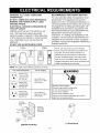 4
4
-
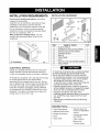 5
5
-
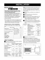 6
6
-
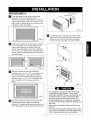 7
7
-
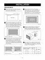 8
8
-
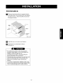 9
9
-
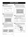 10
10
-
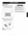 11
11
-
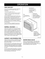 12
12
-
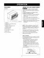 13
13
-
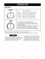 14
14
-
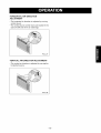 15
15
-
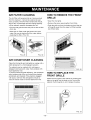 16
16
-
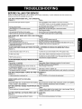 17
17
-
 18
18
-
 19
19
-
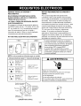 20
20
-
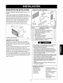 21
21
-
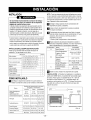 22
22
-
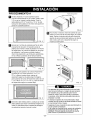 23
23
-
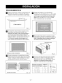 24
24
-
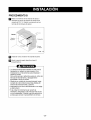 25
25
-
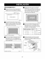 26
26
-
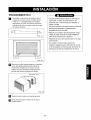 27
27
-
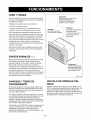 28
28
-
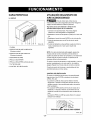 29
29
-
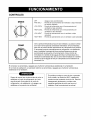 30
30
-
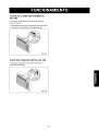 31
31
-
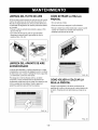 32
32
-
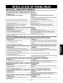 33
33
-
 34
34
-
 35
35
-
 36
36


Kenmore 580.75119 El manual del propietario
- Tipo
- El manual del propietario
- Este manual también es adecuado para
En otros idiomas
- English: Kenmore 580.75119 Owner's manual
Documentos relacionados
-
Kenmore 580.73093300 El manual del propietario
-
Kenmore 580.72107200 El manual del propietario
-
-
-
-
-
-