
Empalmadora mecánica / Mechanical splicer
Ref. 2322
Le adjuntamos algunas sugerencias para
ayudarle a utilizar de forma segura y e -
ciente esta herramienta.
- El gel presente en el interior del empal-
me puede causar irritación en los ojos
si entra en contacto con ellos. Evite esta
situación lavando las manos y la empal-
madora en caso de que el gel entre en
contacto con cualquiera de los dos.
- Use siempre gafas de seguridad cuando
trabaje con bra óptica.
- No mire directamente los extremos de
la bra si se encuentran iluminados por
un láser.
- Esta herramienta se puede utilizar tan-
to anclada sobre una mesa de trabajo,
como sobre la mano directamente.
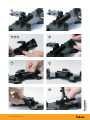
Procedimiento de uso:
1- Cada vez que utilice la herramienta,limpie ambos extremos de la zona en la
que se sitúa el empalme mecánico. Para ello utilice un paño que no desprenda
partículas, humedecido en alcohol isopropílico.
2- Con la palanca de compresión levantada, encaje el empalme mecánico ref.
2328.
Mediante la peladora de precisión ref. 2324, retire entre 30 o 40mm de la funda
protectora que posee la bra óptica. Limpie la bra resultante mediante un
paño que no desprenda partículas, preferentemente humedecido en alcohol
isopropílico.
3- Mediante la cortadora de bra ref. 2323, corte la bra anterior de forma que
posea una longitud entre 12-13mm (12,5 mm sería lo apropiado).
4- Inserte la bra en el empalme (a través de la guía) hasta que se detenga.
5- Introduzca la bra en su punto de sujeción (zona acolchada). Para ello, presio-
ne hacia abajo la pestaña situada a mano izquierda e introduzca la bra en
el soporte de espuma abierto. Libere la pestaña de forma que el soporte de
espuma retenga la bra.
6 - Repita los pasos de 1 a 4 para la segunda bra (lado derecho de la herra-
mienta).
7 - Introduzca la segunda bra en su punto de sujeción (zona acolchada). Co-
mience a empujar la segunda bra en dirección a la primera bra, hasta que
observe como la primera bra comienza a curvarse. Para que la segunda bra
se pueda deslizar, deberá tener pulsada la pestaña derecha, de forma que el
soporte de espuma no retenga su movimiento.
8 - Llegados a este punto, deberá pulsar la pestaña del lado izquierdo, y empujar
la primera bra hacia la segunda, de forma que la curvatura de las dos bras
se iguale.
9 - Presione sobre la palanca de compresión (hacia abajo) para activar el empal-
me mecánico.
10 - Pulse las pestañas izquierda y derecha para retirar los dos extremos de bra
que salen por los extremos del empalme mecánico. A continuación, retire el
empalme mecánico ref. 2328 tirando desde el centro del mismo.
Aviso importante:
La precisión de esta herrramienta no está garantizada. Antes de usar este pro-
ducto, deberá evaluarlo y determinar si es adecuado para el tipo de uso que us-
ted le va a dar. El usuario, asume todos los riesgos y responsabilidades asociadas
a dicho uso.
Next you will nd some suggestions
to help you use this tool safely and
e ciently.
- The gel found inside the splice can
cause eye irritation if in contact with
them. Avoid this by washing hands and
the splicing machine if the gel comes
into contact with either.
- Always wear safety goggles when
working with ber optics.
- Do not look directly at the ends of the
ber if they are illuminated by a laser.
- This tool can be used either fastened on
a desk or directly into your hands.
Instructions for use:
1- Each time you use the tool, thoroughly clean both ends of the area where
the mechanical splice is going to be placed. To do this, use a lint-free cloth
moistened with isopropyl alcohol.
2- Pull the compression lever and t the mechanical splice ref. 2328. By using the
precision stripper ref. 2324, remove 30 or 40 mm of the ber sheath, and clean
the bare bre with a lint-free cloth moistened with isopropyl alcohol.
3- Now cleave the resulting bare ber with the cleaving tool ref. 2323 to leave a
lenth between 12-13 mm (12.5 mm would be appropriate).
4- Insert the ber into the splice (through the guide) until it stops.
5- Now enter the ber within its clamping point (the padded area). To do this,
press down the tab on the left and enter the ber in the foam support that
has been opened. Release the tab so that the foam support hold the ber.
6 - Repeat steps 1 through 4 for the second ber (right side of the tool).
7 - Next, enter the second ber within its clamping point (the padded area). Begin
by pushing the second ber in the direction of the rst ber until you notice
as the rst ber begins to curve. For the second ber can slide, you must have
pressed the right tab, so that the foam support cannot hold its sliding.
8 - At this point, you must press the tab on the left side and push the rst ber
towards the second, so that the curvature of the two bers is as close as
possible.
9 - Press down the compression lever to activate the mechanical splicing.
10 - Press the tabs left and right to release the ber on both sides of the splice
made. Then remove the mechanical splice ref. 2328 pulling from the center.
Important note:
The accuracy of the splicing machine is not guaranteed to make a perfect splice.
Before using this tool, you must evaluate it and determine whether it is suitable
for the type of use you will give. The user assumes all risks and responsibilities
associated with the use herein described.

2011 © Copyright, Televés S.A.
6
7 8
9 10
12
43 5
-
 1
1
-
 2
2

