
Hood
Installation Manual
Models:
HCP50652UC, HCP56652UC

Page 2
Table of
CONTENTS
Safety .................................................................................. 3
Important Safety Instructions ..................................... 3
Electrical Connection ......................................................... 5
Before you begin ............................................................... 6
Tools and parts needed .............................................. 6
Parts included ............................................................. 6
Appliance Dimensions ............................................... 6
Safety Clearances ....................................................... 7
Ventilator Performance Calculation ........................... 8
Installation Procedure ........................................................ 8
Preparing the Installation ........................................... 9
Connect Electrical Supply .......................................... 10
Attachingtheueduct..............................................11
Customer Service .............................................................. 12
Safety
DEFINITIONS
WARNING
This indicates that death or serious injuries may occur as a
result of non-observance of this warning.
CAUTION
This indicates that minor or moderate injuries may occur
as a result of non-observance of this warning.
NOTICE: This indicates that damage to the appliance or
property may occur as a result of non-compliance with this
advisory.
This Bosch appliance is made by
BSH Home Appliances Corporation
1901 Main Street, Suite 600
Irvine, CA 92614
Questions?
1-800-735-4328
www.bosch-home.com/us
We look forward to hearing from you!

Page 3
Safety
IMPORTANT SAFETY INSTRUCTIONS
READ AND SAVE THESE INSTRUCTIONS
INSTALLER: Save these instructions for the local electrical
inspector’s use. Please leave these instructions with this
unit for the owner. Show the owner the location of the
circuit breaker or fuse. Mark it for easy reference.
OWNER: Please retain these instructions for future
reference.
WARNING
If the information in this manual is not followed exactly,
reorshockmayresultcausingpropertydamageor
personal injury.
WARNING
If the information in this manual is not followed
exactly,reorshockmayresultcausingproper-
ty damage, personal injury or death.
- DONOTstoreorusegasolineorotherammable
vapors and liquids in the vicinity of this or any other
apppliance.
- WHAT TO DO IF YOU SMELL GAS
• DO NOT try to light any appliance.
• DO NOT touch any electrical switch.
• DO NOT use any phone in your building.
• Immediately call your gas supplier from a
neighbor’s phone. Follow the gas supplier’s
instructions.
• Ifyoucannotreachyourgassupplier,callthere
department.
- Installation and service must be performed by an
authorized servicer, service agency or the gas supplier.
WARNING
Turn off power circuit at service panel and lock out panel
before wiring this appliance. Requirement: 120 VAC, 60
Hz 15 A. Allow the appliance to cool after the power has
been turned off before servicing the appliance.
WARNING
Automatically Operated Device
To reduce the risk of injury disconnect from power supply
before servicing.
WARNING
TO REDUCE THE RISK OF FIRE, ELECTRIC SHOCK,
OR INJURY TO PERSONS, OBSERVE THE
FOLLOWING:
• Use this unit only in the manner intended by the
manufacturer. If you have questions, contact the
manufacturer at the address or telephone number
listed on the back page.
• Before servicing or cleaning unit, switch power off at
service panel and lock the service disconnecting
means to prevent power from being switched on
accidentally. When the service disconnecting means
cannot be locked, securely fasten a prominent
warning device, such as a tag, to the service panel.
WARNING
DO NOT repair or replace any part of the appliance
unlessspecicallyrecommendedinthemanuals.
Improper installation, service or maintenance can cause
injury or property damage. Refer to this manual for
guidance. All other servicing should be done by an
authorized servicer.
WARNING
ELECTRICAL SHOCK HAZARD
• DO NOT remove connections.
• DO NOT use an extension cord.
• Failure to follow these instructions can
resultindeath,re,orelectricalshock.

Page 4
IMPORTANT SAFETY INSTRUCTIONS
READ AND SAVE THESE INSTRUCTIONS
Grounding Instructions
WARNING
Improper grounding can result in a risk of electric shock.
This appliance must be grounded. In the event of an electri-
cal short circuit, grounding reduces the risk of electric shock
by providing an escape wire for the electric current.
Be sure your appliance is properly installed and grounded
byaqualiedtechnician.Installation,electricalconnections
and grounding must comply with all applicable codes.
If required by the National Electrical Code (or Canadian
Electrical Code), this appliance must be installed on a sepa-
rate branch circuit.
WARNING
Toreducetheriskofreorelectricalshock,DO NOT use
this appliance with any solid state speed device.
Safety Codes and Standards
This appliance complies with one or more of the following
Standards:
• UL 507, The Standard for the Safety of Electric Fans
• CSA C22.2 No. 113, Fans and Ventilators
It is the responsibility of the owner and the installer to de-
termine if additional requirements and/or standards apply
tospecicinstallations.
CAUTION
Unit is heavy and requires at least two people
or proper equipment to move and install.
Hidden surfaces may have sharp edges. Use
caution when handling the appliance. Failure
to do so may result in property damage or
personal injury.
Proposition 65 Warnings
This product may contain a chemical known to the State
of California, which can cause cancer or reproductive
harm. Therefore, the packaging of your product may
bear the following label as required by California:
STATE OF CALIFORNIA PROPOSITION 65 WARNING:
WARNING
Cancer and reproductive harm - www.P65Warnings.ca.gov.
Never modify or alter the construction of the appliance.
For example, do not remove panels, wire covers or
brackets/screws.
CAUTION
For general ventilating use only. DO NOT use to exhaust
hazardous or explosive materials and vapors.
WARNING
Toreducetheriskofre,useonlymetalductwork.
Useaqualiedinstaller.
Remove all tape and packaging before using the
appliance. Destroy the packaging after install. Never allow
children to play with packaging material.
WARNING
TO REDUCE THE RISK OF FIRE, ELECTRIC SHOCK,
OR INJURY TO PERSONS, OBSERVE THE
FOLLOWING:
• Installation work and electrical wiring must be done
byqualiedperson(s)inaccordancewithall
applicablecodesandstandards,includingre-related
construction.
• Sufcientairisneededforpropercombustionand
exhaustingofgasesthroughtheue(chimney)of
fuel burning equipment to prevent back drafting.
Follow the heating equipment manufacturer’s
guideline and safety standards such as those
published by the National Fire Protection
Association (NFPA), and the American Society for
Heating, Refrigeration and Air Conditioning
Engineers (ASHRAE), and the local code authorities.
• When cutting or drilling into wall or ceiling, do not
damage electrical wiring and other hidden utilities.
• Ducted fans must always be vented to the outdoors.

Page 5
Electrical Connection
WARNING
RISK OF ELECTRIC SHOCK
Parts inside the appliance can have sharp edges.
The connection cable can be damaged. Do not
bend or pinch connection cables during installation.
Before connecting the appliance, check the household
electricalsupply.Ensuresufcientfuseprotectionofthe
household electrical supply. The voltage and frequency of
the appliance must match the electrical installation (see
rating plate).
The appliance complies with protection class 1 and must
only be operated in conjunction with a protective conduc-
tor terminal.
An all-pole isolating switch with at least a 3 mm contact
gapmustbettedintheinstallation.Thismustremain
accessible after installation.
Onlyaqualiedelectricianwhotakestheappropriate
regulations into account may lay or replace the
connecting cable. Follow all standards, regulations and laws.
Ensure that the electrical connection meets the require-
ments of the latest version of all applicable standards,
regulations and laws in the appropriate country, especially
the following standards:
National Electrical Code, ANSI/
NFPA 70*, or CSA Standards C22.1-94, Canadian
Electrical Code, Part 1 and C22.2 No.0-M91**.
Haveaqualiedelectricaltechniciancheckthegrounding
of the appliance.
Do not ground with a gas line.
No fuse protection in the neutral or grounding circuit.
Keep these installation instructions. Only connect the
appliance with a copper conductor. If possible, connect
the appliance to a metal cable guide directly to the fuse
box.
Ensure that the wire diameter meets the requirements of
the latest version of all applicable standards and laws in
the appropriate country, especially the following
standards: National Electrical Code, ANSI/NFPA 70*, or
CSA Standards C22.1-94, Canadian Electrical Code, Part
1 and C22.2 No.0-M91**.
Put a protecting hose that is listed in the U.L. or C.S.A. on
both ends of the connecting cable, that is, on the
appliance and on the fuse box.
For copies of the standards listed, contact:
* National Fire Protection Association Batterymarch Park
Quincy, Massachusetts 02269
** CSA International 8501 East Pleasant Valley Road
Cleveland, Ohio 44131-5575
IMPORTANT SAFETY INSTRUCTIONS
READ AND SAVE THESE INSTRUCTIONS
WARNING
TO REDUCE THE RISK OF A RANGE TOP GREASE
FIRE:
• Never leave surface units unattended at high
settings.
Boilovers cause smoking and greasy spillovers that
may ignite. Heat oils slowly on low or medium
settings.
• Always turn hood ON when cooking at high heat
orwhencookingambéingfood(i.e.CrepesSuzette,
Cherries Jubilee, Peppercorn Beef Flambe).
• Clean ventilating fans frequently. Grease should
notbeallowedtoaccumulateonfanorlter.
• Use proper pan size. Always use cookware
appropriate for the size of the surface element.
WARNING
TO REDUCE THE RISK OF INJURY TO PERSONS IN
THE EVENT OF A RANGE TOP GREASE FIRE,
OBSERVE THE FOLLOWING:
a
• SMOTHERFLAMESwithaclosettinglid,cookie
sheet, or metal tray, then turn off the burner. BE
CAREFULTOPREVENTBURNS.Iftheamesdonot
go out immediately, EVACUATE AND CALL THE
FIRE DEPARTMENT.
• NEVER PICK UP A FLAMING PAN - you may get
burned.
• DO NOT USE WATER, including wet dishcloths or
towels - a violent steam explosion will result.
• Use an extinguisher ONLY if:
a) You know you have a class ABC extinguisher,
and you already know how to operate it.
b) Thereissmallandcontainedintheareawhere
it started.
c) Theredepartmentisbeingcalled.
d) Youcanghttherewithyourbacktoanexit.
a
Based on “Kitchen Fire Safety Tips” published by NFPA.

Page 6
Before you begin
Tools and Parts Needed
• Measuring tape
• Pencil
• Phillips screwdriver (Posidrive) #2
• Drill with the following bits:
5
⁄16” (7.9 mm) and
3
⁄8”
(9.5 mm)
• Spirit-level
• Aluminum tape (DO NOT use insulating tape)
• Exhaustchannel(congurationdependsonthe
installation situation)
• Additional sheet metal screws (if necessary for
installation of the exhaust air duct)
• Saw
• Home power supply cable
• 1/2” (13 mm) UL listed or CSA approved strain relief
• Three UL Listed wire connectors
Parts Included
• Extractorhoodwithfan,back-pressureap
• Lamps, already installed
• Metalgreaselter
• Flue duct
• Drill template
• 1xanglebracketfortheueduct
• Installation manual and instructions for use
• 6x screws, 5x45 mm
• 12x screws, 4.2x8 mm
• 2x washers, 6.4x18 mm
• 2x hollow wall plugs, 8x40 mm
• 4x hollow wall plugs, 10x50 mm
• Torx adapter, 10 & 20
NOTE:Carefullyremovetheprotectivelmfromtheduct
cover and hood assembly prior to the start of the installation.
Use one hand to maintain the assembly/duct cover steady
whiletheotherhandremovestheprotectivelm.
Use gloves at all time.
Appliance Dimensions
30" (762 mm)
36" (914 mm)
A
19
11
/
16
"
(500 mm)
7
7
/
8
"
(200 mm)
10
3
/
4
"
(273 mm)
13
3
/
16
"
(335 mm)
5¾"
(146 mm)
A Only for circulating-air mode:
*Max. 43
1
⁄2" (1106 mm)
*Min. 29" (734 mm)
Only for ducted operation:
*Max. 39
1
⁄2" (1006 mm)
*Min. 25" (633 mm)

Page 7
Fan operation
Note: Ventilation may not exit through an already
operational smoke or exhaust chimney, nor a duct used
for ventilating furnace installation areas.
• If the ventilation is intended to pass through a smoke
or exhaust chimney that is not in operation, the
responsible area heating inspector must give approval.
• If the ventilation passes through an external wall, use a
telescope wall sleeve.
Ventilation line
Note: The device manufacturer is not responsible for the
operation or complaints associated with the pipe section.
• The ventilation opening and the exhaust air ducts must
be made according to the local requirements.
• The device achieves its optimum performance by
means of a short, straight exhaust air pipe and as
large a pipe diameter as possible.
• As a result of long rough exhaust air pipes, many pipe
bends or too-small diameters, the optimum extraction
performance is not achieved and fan noise is increased.
• The pipes or hoses for laying the exhaust air line must
consist of non-combustible material.
• Smooth the connection area of the pipes before
installation.
• Seal the connection points of the pipes appropriately.
Round pipes
An inner diameter of Ø 8” (200 mm) is recommended.
Checking the wall
• The wall must be level, vertical and adequately loa
bearing.
• The depth of the bore holes must be the same length
as the screws. The wall plugs must have a secure grip.
• The enclosed screws and wall plugs are suitable for
solid brickwork. Suitable fasteners must be used for
other structures.
Safety clearances
WARNING
RISK OF FIRE
Greasedepositsinthegreaseltercancatchre.
The given safety clearance must be observed to avoid
heatbuildup.Observethespecicationsforyourcooking
appliance. If gas and electric cooktops are used together,
the largest given clearance applies.
The appliance may only be installed directly next to a
cabinet or wall on one side. The wall or cabinet clearance
must be at least 2” (50 mm).
The clearance between the shelf on the cooktop and the
bottom of the extractor hood may not be less than 30” (762
mm) in the case of electric cooktops and gas or combined
ranges.
If the installation instructions for the gas cooking
appliance specify a larger distance, this must be taken into
account.
Electrical & Gas cooktop
min. 30" (762 mm)

Page 8
Installation Procedure
The ducting from this fan to the outside of the building has
astrongeffectontheairow,noiseandenergyuseofthe
fan. Use the shortest, straightest duct routing possible for
best performance, and avoid installing the fan with smaller
ducts than recommended. Insulation around the ducts can
reduce energy loss and inhibit mold growth. Fans installed
withexistingductsmaynotachievetheirratedairow.
Ensure duct joints and exterior penetrations are sealed
with caulk or other similar material to create an air-tight
path and to minimize building heat loss and gain and
reduce the potential for condensation.
Place/wrap insulation around duct and/or fan to in order to
minimize possible condensation buildup within the duct,
building heat loss and gain.
CAUTION
Ensure that there are no electric wires, gas or water pipes
in the area where holes are to be made.
Ventilator Performance Calculation
Size (in)
Eq uivalent
Length (ft)
Size (in)
Eq uivalent
Length (ft)
61.2
61
0
80.7
10 0.6
3¼" x 10", straight N/A1
3¼" x 10", Center
reverse elbow, right
N/
A2
5
3¼" x 14", straight N/A0.7
3¼" x 10", Left
reverse elbow
N/
A1
5
3¼" x 10", Right
reverse elbow
N/
A2
5
612
62
86
82
10
10 2
65
62
2
5
83
82
2
2
10
10
3¼" x 10",
90° elbow, round
N/A5
2’ long, 3¼" x 10" flexN/A 20
3¼" x 10",
45° elbow, round
N/A15
3¼" x 10", Flat elbowN/A 20
61
810
82
3¼" x 10", Roof jack
and shutter
N/A
65
61
0
NOTE: These commonly used installation parts can be purchased at a
local hardware store. Bosch does not manufacture all these parts.
Round wall cap
Round roof cap
3¼" x 10" to round
90° elbow,
Duct Piece
3¼" x 10" Center
reverse elbow, left
15N/A
Round to 3¼" x 10"
3¼" x 10" to round
Round to 3¼" x 10"
90° elbow,
Duct Piece
Smooth, straight
90° elbow, round
45° elbow, round
Roof
Venting
Wall
Venting
Non Vented
(Recirculating)*
A. Roof ca
p
B. 8" (20.3 cm)
round vent
C. Seal duct joints
with duct tape/
caulk
A. Wall cap
B. 8" (20.3 cm)
round vent
C. Seal duct joints
with duct tape/
caulk
A. Diverter
B. 8" (20.3 cm)
round vent
C. Seal duct joints
with duct tape/
caulk
A
B
C
A
B
C
B
C

Page 9
Preparing the installation
1. Mark a vertical center line on the wall from the ceiling
to the lower edge of the extractor hood.
2. Align the drill template on the center line and the
bottom edge of the extractor hood and glue on.
3. Mark positions for the screws and the contour of the
attachment area.
4. Markholesfortheue’sanglebrackets.Thecenterof
the angle bracket is marked with a hole. Place the
angle brackets in the center of the center line, align
them horizontally and mark the positions of the holes.
B
C
A
A Ceiling
B Wall
C Centerline
Fitting the wall retainer
1. Drill holes with Ø 5/16” (7.9 mm) for the angle bracket.
2. Pressinthewallplugsushwiththewall.
3. Screw screws (5x34 mm) into the wall plugs by hand
in order to spread the plugs apart.
4. Unscrew screws.
5. Screwontheanglebracketfortheueduct.
Making the ceiling breakthrough
1. Using a spirit level, extend the center line of the drill
template to the ceiling.
2. Mark the ceiling breakthrough (Ø 8 1/2” (216 mm)) at
least 4 5/8” (117 mm) away from the wall.
Making the wall breakthrough
1. Using a spirit level, extend the center line of the drill
template to the ceiling.
2. Depending on the curved section of the wall
breakthrough (Ø 8 1/2” (216 mm)) mark at least
26 1/2” (660 mm) above the bottom edge of the
extractor hood.
Mounting the back-pressure flap
1. Using 4 screws (4.2 x 8 mm), attach the air transition
spacer to the hood.
2. Using 4 screws (4.2 x 8 mm), attach the back-pressure
apandtheairtransitionspacer.
A
B
A Transition Spacer
B Air Transition
Mounting the extractor hood on the wall
WARNING
RISK OF INJURY
The appliance is heavy. To move the appliance, 2 people
are required. Use only suitable tools and equipment.
1. Initially remove the protective foil from the back of the
appliance and, following installation, remove foil
completely.
2. Mark the upper holes on the wall.
Note: Ensure that the holes are horizontal and aligned
centered on the center line.
3. Drill the upper holes. Adhere to a distance of 1/4”
(6 mm) between the wall and screw head.
4. Removegreaselters.
5. Hang the extractor hood on the upper screws on the
wall.
6. Mark holes for the lower holes.
7. Remove the extractor hood from the wall.
8. Drill the lower holes.
9. Hang the extractor hood on the upper screws on the
wall.

Page 10
10. Tighten the upper and lower screws by hand.
Connecting the air extractor (only for ducted operation)
Note: If an aluminum pipe is used, smooth the connection
area beforehand.
1. Attach exhaust air pipe and seal.
2. Checkwhethertheback-pressureapworks.
Mounting the recirculation model
(only for circulating-air mode)
1. Use 4 screws (4x8 mm) to screw the housing to the
angle bracket.
A
B
C
A Screws
B Recirculation module
C Angle bracket
2. Measure the distance (x) between the bottom edge of
the housing for the recirculation module and the
bottomedgeoftheback-pressureap.
A
x
B
C
D
A Recirculation module
B Clamps
C Flue duct
D Exhaust air duct
3. Shorten the exhaust air pipe to the length measured.
4. Remove the recirculation module.
5. Push the exhaust air pipe onto the bottom side of the
recirculation module.
6. Position the recirculation module with exhaust air pipe
over the air extraction duct of the extractor hood.
7. Use 4 screws to fasten the recirculation module to the
angle bracket.
8. Secure connections with clamps.
Connect Electrical Supply
WARNING
RISK OF ELECTRIC SHOCK
Before wiring the appliance, interrupt the main electrical
circuit at the electrical control cabinet. A circuit with 120
VAC, 15 or 20 Ampere is required.
Grounding notes: this appliance is equipped with a
distributor box with 3 cables. Use the green-yellow cable
for grounding the appliance. Connect the green-yellow
cable to the grounding cable on the house connection to
prevent electric sthock. Do not under any circumstances
damage or remove the green-yellow cable. Non-adheren-
ce can cause serious injuries or electric shock.
1. Unplug the cable connector located on the top of the
junction box.
2. Remove the cable passage and the junction box cover.
B
A
A Cable passage
B Cover of the junction box
3. Connect 1/2” (12.7 mm) strain relief to the junction box.
4. Run home power supply cable through strain relief,
into terminal box.
5. Use UL listed wire connectors and connect black wires
(C) together.
6. Use UL listed wire connectors and connect white wires
(D) together.

Page 11
7. Connect green (or bare) ground wire from home power
supply to yellow-green ground wire (E) in terminal box
using UL listed wire connectors.
B
A
C
D
E
A Installation pipe
B Cable connector listed in UL
C Black wires
D White wires
E Yellow-green ground wire
8. Tighten strain relief screw.
9. Install the junction box cover.
10. Plug the cable connector located on the top of the
junction box.
Attaching flue duct
Hidden surfaces may have sharp edges. Use caution
when reaching behind or under appliance.
1. Removetheprotectivefoilfrombothueducts.
2. Pushoneueductintotheother.
Notes
• To prevent scratches, lay paper over the edges of
thelowerueducttoprotectthesurface.
• Forductedoperation,turntheupperueductso
that the ventilation slots point downward.
3. Remove the protective foil from the extractor hood.
4. Placeueductsontheappliance.
5. Pushtheinnerueductupwardsandattachittothe
angle brackets on the left and right.
6. Screwtheueducttothesidesoftheanglebracket
using two screws.
AB
7. Fastenthelowerpartoftheueductusingtwo
screws.
8. Removetheprotectivepaperfromthelowerueduct.
9. Installmetal-meshgreaselter.
Removing the appliance
1. Removethemetal-meshgreaselter.
2. Loosentheueduct.
3. Disconnect the appliance from the power supply.
4. Loosen the exhaust air lines.
5. Loosen screws for fastening the appliance.
6. Remove the appliance.

Page 12
Customer service
Our customer service department is there for you if your
appliance requires repair. When calling, please give the Pro-
duct Number (P-No.) and the Serial Number (S-No.) so that
wecanofferyouthebestservice.Theidenticationplate
listing the numbers can be found inside of the appliance
(removemetalgreaseltertondit).
So that you don’t have to search for them when you need
them, you can enter your appliance information and the
customer service number here.
P-No. S-No.
Customer service O
Please note that a service visit to provide instruction on the
use of the appliance is not covered by the warranty.
Pleasendthecontactdataofallcountriesinthe
enclosed customer service list.
To book service or for product advice
US 800 944 2904
toll-free

Page 13
Table des
MATIÈRES
Sécurité..............................................................................14
ConsignesdeSécuritéImportantes...........................14
Branchementélectrique....................................................17
Avant de commencer ........................................................ 17
Outilsetpiècesnécessaires...................................... 17
Pièces comprises ........................................................ 17
Cotes de l’apparei ...................................................... 18
Distancesdesécurité.................................................18
Longueurséquivalentesdeconduites
pourpiècesdetransitionhabituellementutilisée.....19
Procédured’installation.....................................................19
Preparing the Installation ........................................... 20
Connect Electrical Supply .......................................... 21
Attachingtheueduct..............................................22
Service après-vente ............................................................ 23
Dénitions de
SÉCURITÉ
AVERTISSEMENT
Ceci indique que le non respect de cet avertissement
peut entraîner des blessures graves, voire la mort.
ATTENTION
Ceci indique que le non respect de cet avertissement
peutentraînerdesblessureslégèresoumodérées.
AVIS:Ceciindiquequelanon-conformitéàcetavisde
sécuritépeutentraînerdesdégâtsàl’appareilouàlapro-
priété.
Remarque: Ceci vous avertit que d’importantes informa-
tions et/ou conseils sont fournis.
Cet appareil électroménager de Bosch
est fait par BSH Home Appliances LtD
6696 Financial Drive, Unit 3
Mississauga, ON L5N 7J6
Des questions?
1-800-735-4328
www.bosch-home.com/us
Nous attendons de vos nouvelles!

Page 14
Sécurité
CONSIGNES DE SÉCURITÉ IMPORTANTES
LIRE ET CONSERVER CES CONSIGNES
INSTALLATEUR: Conservezcesconsignesàl’intentionde
l’inspecteurélectriquelocal.Laissezcesconsignesavec
l’appareilàl’intentiondupropriétaire.Montrezauproprié-
taire l’emplacement du disjoncteur ou du fusible du circuit.
Identiezsapositionpourpouvoirleretrouverfacilement.
PROPRIÉTAIRE: Prière de conserver ces consignes pour
pouvoirs’yréférerultérieurement.
AVERTISSEMENT
Silesconsignesduprésentmanuelnesontpassuivies
àlalettre,ilyaunrisqued’incendieoud’électrocution
pouvantentraînerdesdommagesmatérielsoudesbles-
sures.
AVERTISSEMENT
Silesconsignesduprésentmanuelnesontpas
suiviesàlalettre,ilyaunrisqued’incendieou
d’électrocutionpouvantentraînerdesdom-
magesmatériels,desblessuresoulamort.
- NE PAS conserver ou utiliser de l’essence ou d’autres
liquidesetvapeursinammablesàproximitédecet
appareilélectroménageroudetoutautreappareil.
- QUE FAIRE SI VOUS PERCEVEZ UNE ODEUR DE GAZ
• NE PAS essayer de mettre un appareil
électroménagersoustension.
• NEPAStoucherd’interrupteurdecourantélectrique.
• NEPASutiliserdetéléphonesdansl’édice.
• Communiquerimmédiatementaveclefournisseur
degazdepuisl’appareiltéléphoniqued’unvoisin.
Respecter les directives du fournisseur de gaz.
• S’il s’avère impossible de joindre le fournisseur
de gaz, communiquer avec les pompiers.
- Utiliserlesservicesd’untechnicienenréparationou
d’uneagencederéparationsautorisés,oule
fournisseurdegaz,pourprocéderàl’installationet
auxréparations.
AVERTISSEMENT
Couperl’alimentationducircuitélectriqueauboîtieràfu-
siblesoudesdisjoncteursetleverrouilleravantdecâbler
cetappareilélectroménager.Exigences:120Vc.a.,60
Hzet15A.Aprèslacoupuredel’alimentationélectrique,
laisserrefroidirl’appareilélectroménageravantdeprocé-
derauxréparations.
AVERTISSEMENT
Dispositifàfonctionnementautomatique
Couperl’alimentationélectriqueavanttouteréparation
pourréduirelerisquedeblessure.
AVERTISSEMENT
POUR RÉDUIRE LE RISQUE D’INCENDIE,
D’ÉLECTROCUTION OU DE BLESSURES, RESPECTER
LES INDICATIONS SUIVANTES:
• Utilisercetappareiluniquementdelafaçonprévue
par le fabricant. Pour toutes questions, communiquer
aveclefabricantàl’adressedeladernièrepageouau
numérodetéléphoneinscrit.
• Avantderépareroudenettoyerl’appareil,couper
l’alimentationélectriqueaudispositifde
sectionnementetleverrouillerpouréviterque
l’alimentationnesoitrétablieaccidentellement.
Lorsque le dispositif de sectionnement ne peut pas
êtreverrouillé,xerunaccessoired’avertissement
visibleetadéquat,commeuneétiquette,auboîtierà
fusibles ou des disjoncteurs.
AVERTISSEMENT
NE PASréparerouremplacerunepiècedel’appareil
électroménager,àmoinsquelesmanuelsrecommandent
de le faire.
Uneinstallation,uneréparationouunentretien
incorrect(e) peut entraîner des blessures ou des dom-
magesmatériels.Consulterleprésentmanuelpour
connaîtrelesdirectives.Touteautreréparationdoitêtre
effectuéeparuntechnicienenréparationautorisé.
AVERTISSEMENT
RISQUE D’ÉLECTROCUTION
• NE PAS enlever les raccords.
• NE PAS utiliser de rallonge.
• Toutmanquementàcesdirectivespeut
entraîner la mort ou une

Page 15
CONSIGNES DE SÉCURITÉ IMPORTANTES
LIRE ET CONSERVER CES CONSIGNES
Directives de mise à la terre
AVERTISSEMENT
Unemiseàlaterreinadéquatepeutentraînerunrisque
d’électrocution.
Cetappareilélectroménagerdoitêtremisàlaterre.En
casdecourt-circuitélectrique,lamiseàlaterreréduitle
risqued’électrocutionenoffrantaucourantélectriqueunl
d’évacuation.
Assurez-vousquel’appareilestcorrectementinstalléet
misàlaterreparuntechnicienqualié.L’installation,les
raccordementsélectriquesetlamiseàlaterredoiventêtre
conformes avec tous les codes en vigueur.
S’ilyalieu,conformémentauCodenationaldel’électricité
(ouauCodecanadiendel’électricité),cetappareilélec-
troménagerdoitêtreinstallésuruncircuitdedérivation
distinct
AVERTISSEMENT
NE PASutilisercetappareilélectroménageravecundis-
positif de contrôle de la vitesse semi-conducteur pour
Codes et normes de sécurité
Cetappareilélectroménagerestconformeàuneouplu-
sieurs des normes suivantes :
• UL507,Normeenmatièredesécuritépourles
ventilateursélectriques
• CSA-C22.2 no 113, Ventilateurs
Ilincombeaupropriétaireetàl’installateurdedéterminer
si des exigences et/ou normes additionnelles s’appliquent
pourdesinstallationsspéciques.
MISE EN GARDE
L’appareilestlourdetsondéplacementetins-
tallation exigent au moins deux personnes ou
encoreunéquipementapproprié.
Dessurfacescachéespeuventavoirdesre-
bords tranchants. Faire attention en manipulant
l’appareilélectroménager.Toutmanquement
àcetteconsignepourraitentraînerdesdom-
magesmatérielsoudesblessures.
Nejamaismodiernialtérerlastructure(fabrication)de
l’appareilélectroménager.Parexemple,nepasretirerles
panneaux,lescouvre-ls,lessupports,leséquerresde
xationoulesvis.
Avertissement issu de la proposition 65
Ce produit pourrait contenir un produit chimique reconnu
parl’ÉtatdelaCaliforniecommecancérigèneouayantdes
effetsnocifssurlareproduction.Parconséquent,
l’emballagedevotreproduitpourraitporterl’étiquette
suivante, comme requis par la Californie:
AVERTISSEMENT ISSUE DE LA PROPOSITION 65 DE
L’ÉTAT DE LA CALIFORNIE:
AVERTISSEMENT
Canceretdommagesàlareproduction–
www.P65Warnings.ca.gov.
MISE EN GARDE
Uniquementauxnsdeventilationgénérale.NE PAS
utiliserpourévacuerdesmatièresetdesgazdangereux
ou explosifs.
AVERTISSEMENT
Pourréduirelerisqued’incendie,utiliseruniquementdes
systèmesdegaines/conduitesenmétal.
Utilisezlesservicesd’uninstallateurqualié.
Retirez tout le ruban et l’emballage avant d’utiliser
l’appareilélectroménager.Jetezl’emballageaprès
l’installation. Ne laissez jamais les enfants jouer avec le
matérield’emballage.
AVERTISSEMENT
POUR RÉDUIRE LE RISQUE D’INCENDIE,
D’ÉLECTROCUTION OU DE BLESSURES, RESPECTER
LES INDICATIONS SUIVANTES :
• Lestravauxd’aménagementetdecâblageélectrique
doiventêtreexécutéspardupersonnelqualiéen
conformitéàtouslescodesetàtouteslesnormes
de construction en vigueur, incluant ceux concernant
les incendies.
• Unapportd’airsufsantestnécessairepourlabonne
combustionetévacuationdesgazparlecarneau
(cheminée),émanantdetoutappareildecombustion
and’éviterlerefoulementdel’air.Respecterles
lignes directrices du fabricant des appareils de
chauffageetlesnormesdesécuritécommecelles
établiesparlaNationalFireProtectionAssociation
(NFPA), la American Society for Heating, Refrigeration
and Air Conditioning Engineers (ASHRAE) et les c
desdesautoritéslocales.

Page 16
CONSIGNES DE SÉCURITÉ IMPORTANTES
LIRE ET CONSERVER CES CONSIGNES
• En coupant ou perçant un mur ou un plafond pour
l’installation de l’appareil, s’assurer de ne pas
endommagerlecâblageélectriqueetlesautres
servicespublicsmasqués.
• Lesventilateursraccordésàuneconduitedoivent
toujoursévacuerl’airversl’extérieur.
AVERTISSEMENT
POUR RÉDUIRE LE RISQUE D’INCENDIE DE GRAISSE
DE CUISINIÈRE:
• Ne jamais laisser la surface de cuisson sans
surveillanceàfeuvif.
Lesdébordementscausentdelafuméeetlesrésidus
graisseuxpeuvents’enammer.Fairechauffer
lentementleshuilesàfeudouxoumoyen.
• Toujours faire FONCTIONNER la hotte lorsque vous
cuisinezàfeuvifoupourambercertainsplats
(c.-à-d.,crêpesSuzette,cerisesJubilé,steakaupoivre
ambé).
• Nettoyerrégulièrementlesventilateurs.Nepaslaisser
lagraisses’accumulersurleventilateurouleltre.
• Utiliserdescasserolesdetailleappropriée.Toujours
utiliserdesustensilesdecuisineadaptésàlataillede
l’élémentdecuisson.
AVERTISSEMENT
POUR RÉDUIRE LE RISQUE DE BLESSURES EN CAS
D’INCENDIE DE GRAISSE DE CUISINIÈRE, RESPECTER
LES CONSIGNES SUIVANTES:
a
• ÉTOUFFER LES FLAMMES avec un gros couvercle
bienajusté,uneplaqueàbiscuitsouunplateaude
métalpuisfermerlebrûleur.ÊTREPRUDENT,
ÉVITERLESBRÛLURES.Silesammesne
s’éteignentpasimmédiatement,ÉVACUERLES
LIEUX ET APPELER LES POMPIERS.
• NEJAMAISSOULEVERUNEPOÊLEENFEU:vou
risquezd’êtrebrûlé.
• NEPASUTILISERD’EAU,ycomprisuntorchonà
vaisselleouuneserviettemouillé,celaentraînera
une explosion violente de vapeur.
• Utiliser un extincteur UNIQUEMENT si:
a) Vous savez que vous disposez d’un extincteur de
classeABCetsavezdéjàcommentl’utiliser.
b) Lefeuestpetitetconcentrédanslazoneoùila
commencé.
c) Vousavezappelélespompiers.
d) Vous pouvez combattre l’incendie avec une sortie
derrière vous.
a
Explicationsfondéessur«KitchenFireSafetyTips»
(Conseilsdesécuritéencasd’incendiedecuisine)pu-
bliéesparlaNFPA.

Page 17
Avant de commencer
Outils et pièces nécessaires
• Décamètreàruban
• Crayon
• Tournevis Phillips (Posidrive) #2
• Perceuse avec les forets suivants : 5/16” (7,9 mm) et
3/8” (9,5 mm)
• Niveauàbulle
• Ruban en aluminium (NE PAS utiliser un ruban isolant)
• Canald’évacuationd’air(lacongurationdépenddela
situation de montage).
• Visàtôlesupplémentaires(sinécessairespour
l’installationduconduitd’évacuation)
• Scie
• Cordon d’alimentation
• Réducteurdetensionde1/2”(13mm)répertoriéULou
approuvéparCSA.
• TroisconnecteursdellistésUL
Pièces comprises
• Hotte aspirante avec ventilateur, volet anti-refoulement
• Lampe,déjàmontée
• Filtreàgraisseenmétal
• Capotdecheminée
• Gabarit de perçage
• 1cornièrederetenuepourlecapotdecheminée
• Notice d’utilisation et d’installation
• 6 vis, 5 x 45 mm
• 12 vis, 4,2 x 8 mm
• 2x rondelles
• 2x chevilles pour corps creux, 8x40 mm
• 4x chevilles pour corps creux,10x50 mm
• Adaptateur Torx, 10 & 20
REMARQUE:Retirezdélicatementlelmdeprotection
ducouvercleduconduitetducapotavantledébutde
l’installation. Utilisez une main pour maintenir le couvercle de
l’ensemble / conduit stable tandis que l’autre main enlève le
lmdeprotection.
Branchement électrique
AVERTISSEMENT
RISQUE DE CHOC ÉLECTRIQUE
Les pièces se trouvant dans l’appareil peuvent
présenterdesarêtesvives.Lecordondebranchement
peutêtreendommagé.Nepascoudernicoincerlecor-
don de branchement pendant la pose.
Avantderaccorderl’appareil,vérierl’installation
domestique.Veilleràcequelaprotectiondel’installation
domestiquesoitappropriée.Latensionetlafréquencede
l’appareildoiventcorrespondreàl’installationélectrique
(voirlaplaquesignalétique).
L’appareilrépondàlaclassedeprotectionIetdoit
uniquementêtreutiliséavecuneprisedeterre.
Un sectionneur omnipolaire avec un interstice d’ouverture
decontactd’aumoins3mmdoitêtreprésentdans
l’installation. Celui-ci doit encore être accessible après
l’encastrement.
Seulunélectricienagrééesthabilitéàinstallerouà
remplacerlecâblederaccordement,enrespectantles
prescriptions en vigueur.
Respecter toutes les normes et lois en vigueur.
Veilleràcequeleraccordementélectriquerépondeaux
exigences de toutes les normes et lois applicables dans
lepayscorrespondantetauxspécicationsdeséditions
lesplusrécentesdesnormessuivantes:National
Electrical Code, ANSI/NFPA 70*, ou normes
CSAC22.1-94,Codecanadiendel’électricité,partie1et
C22.2 No.0-M91**.
Fairecontrôlerparunélectricienleraccordementàlaterre
de l’appareil.
Nepasmettreàlaterreavecunecanalisationdegaz.
S’assurer de ne pas avoir de fusible dans le circuit
électriqueneutreoudemiseàlaterre.
Conserver la notice de montage. Raccorder l’appareil
uniquementavecuncâblagedecuivre.Raccorder
l’appareilsipossibleavecunguidedecâblemétallique
directementauboîtieràfusibles.
Lediamètreduldoitrépondreauxexigencesdetoutes
les normes et lois applicables dans le pays
correspondantetauxspécicationsdeséditionslesplus
récentesdesnormessuivantes:NationalElectricalCode
ANSI/NFPA 70*, ou normes CSA C22.1-94, Code
canadiendel’électricité,partie1etC22.2No.0-M91**.
FixerunegainedeprotectiongurantdanslalisteU.L.
ouC.S.A.auxdeuxextrémitésducâblederaccordement,
àsavoirauniveaudel’appareiletauboîtieràfusibles.
Vouspouvezobtenirdescopiesdesnormesmentionnées
auprès de :
* National Fire Protection Association Batterymarch Park
Quincy, Massachusetts 02269
** CSA International 8501 East Pleasant Valley Road
Cleveland, Ohio 44131-5575.

Page 18
Cotes de l’apparei
30" (762 mm)
36" (914 mm)
A
19
11
/
16
"
(500 mm)
7
7
/
8
"
(200 mm)
10
3
/
4
"
(273 mm)
13
3
/
16
"
(335 mm)
5¾"
(146 mm)
A Uniquement en cas de mode recirculation de l’air :
*Max. 43
1
⁄2" (1106 mm)
*Min. 29" (734 mm)
Uniquement en cas de mode evacuation de l’air :
*Max. 39
1
⁄2" (1006 mm)
*Min. 25" (633 mm)
Distances de sécurité
AVERTISSEMENT
RISQUE D’INCENDIE
Lesdépôtsdegraissedansleltreàgraissepeuvent
s’enammer.Ladistancedesécuritérecommandéedoit
êtrerespectéeand’éviteruneaccumulationdechaleur.
Veuillezrespecterlesspécicationsdevotreappareil
decuisson.Sidescuisinièresélectriquesetàgazsont
utiliséesensemble,laplusgrandedistanceindiquée
s’applique.
L’appareilpeutseulementêtreinstallédirectementcontre
unmurouunearmoiresuruncôté.
L’espacement du mur ou de l’armoire doit être d’au
moins 2” (50 mm).
La distance entre la surface de rangement sur la table de
cuisson et le dessous de la hotte ne doit pas être
inférieureà30”(760mm)pourlestablesdecuisson
électriquesetpourlescuisinièresàgazoucombinées.
Si les instructions pour l’installation de l’appareil de cuisson
augazspécientuneplusgrandedistance,cellecidoitêtre
prise en compte.
Tabledecuissonaugazetélectrique
min. 30" (762 mm)
Mode évacuation
Remarque: Ilnefautpasrejeterl’airusédansune
cheminéed’évacuationenservice,nidansunconduit
servantàlaventilationdepiècesoùsontinstallésdes
foyers.
• Pourrejeterl’airdansunconduitdefuméesquin’est
pas en service, il faut demander l’accord du maître
ramoneurcompétent.
• Sil’airestévacuéàtraverslemurextérieurde
l’habitation,ilfaututiliseruncaissonmuraltélescopique.
Conduit d’évacuation
Remarque:Lefabricantdel’appareildéclinetoutegarantie
encasderéclamationimputableàdesproblèmesliésau
parcours des conduits.
• L’ouvertured’évacuationd’airetlesconduits
d’évacuationdoiventêtreexécutésenfonctiondes
conditions locales.
• L’appareilatteindraunrendementsupérieursile
conduitd’évacuationestcourtetdroitetqueson
diamètre est grand.
• Desconduitsd’évacuationd’airlongs,auxparois
rugueuses, comportant plusieurs coudes ou des
diamètres trop petits, empêchent d’atteindre une
puissance d’aspiration optimale et le ventilateur
devient plus bruyant.
• Les tuyaux rigides ou souples constituant le conduit
d’évacuationdoiventêtreenmatériauininammable.
• Lisser la zone de raccordement des tuyaux avant le
montage.
• Étancher les zones de jonction.
Tuyaux ronds
NousrecommandonsundiamètreintérieurdeØ8”(200mm).
Vérifier le mur
• Le mur doit être plat, vertical et offrir une portance
sufsante.
• Laprofondeurdestrouspercésdoitêtreadaptéeàla
longueur des vis. Les chevilles doivent offrir une
retenuesûre.
• Les vis et chevilles fournies conviennent pour la
maçonneriemassive.Enprésenced’autresmatériaux
deconstruction,ilfaututiliserdesmoyensdexation
correspondants.

Page 19
Longueurséquivalentesdeconduitespourpiècesdetransitionhabituellementutilisée
Taille
(po)
Taille
(po)
Longueur
équivalente
(pi)
Longueur
équivalente
(pi)
61.2
61
0
80.7
10 0.6
3¼ x 10 po, droit S.O. 1
S.O. 25
3¼ x 14 po, droit S.O. 0.7
S.O. 15
S.O. 25
612
62
86
82
10
10 2
65
62
2
5
83
82
2
2
10
10
3¼ x 10 po
coude 90 degrés, rond
S.O. 5
Gaine souple, 2 pi long,
3¼ x 10 po
S.O. 20
3¼ x 10 po,
coude 45 degrés, rond
S.O. 15
3¼ x 10 po,
coude plat
S.O. 20
61
810
82
Trémie de cheminée et
volet d’obturation,
3¼ x 10 po
S.O.
65
61
0
REMARQUE: Ces pièces courantes pour installation sont offertes dans
les quincailleries locales. Bosch ne fabrique pas toutes ces pièces.
Lisse, ronde
Lisse de toit, ronde
15S.O.
Orifice rond jusqu’à
3¼ x 10 po
3¼ x 10 po
jusqu’à l’orifice rond
Pièce du système Pièce du système
Lisse, droite
Coude 90 degrés,
rond
Coude 45 degrés,
rond
Orifice rond jusqu’à
3¼ x 10 po,
avec coude 90 degrés
3¼ x 10 po avec
coude de 90 degrés,
rond
3¼ x 10 po coude
centré, inversé,
gauche
3¼ x 10 po coude
centré, inversé,
droit
3¼ x 10 po coude à
gauche, inversé
3¼ x 10 po coude
droit, inversé
Procédure d’installation
Lesconduitsmenantdelahotteàl’extérieurdubâtiment
ont un impact important sur la circulation d’air, le bruit et la
consommationénergétiquedelahotte.Utilisezla
congurationdeconduitslapluscourteetlaplusdroite
possiblepourunrendementoptimal,etévitezd’installerla
hotte avec des conduits d’une taille plus petite que celle
recommandée.L’isolationautourdesconduitspeutréduire
laperteénergétiqueetprévenirlaformationdemoisissure.
Deshottesinstalléesavecdesconduitsdéjàenplace
peuventnepasatteindreleurdébitd’airnominal.
ATTENTION
Veillezàcequ’iln’yaitpasdeconduitesélectriques,
ou tuyaux de gaz et d’eau au niveau des perçages.
Ventilation
par le toit
Ventilation
murale
Aucune
ventilation*
(Recirculation)
A. Capuchon de toit
B. Conduit rond de
8 po (20,3 cm)
C. Sceller les joints
des conduits avec
du ruban adhésif/
produit calfeutrant
A. Capuchon mural
B. Conduit rond de
8 po (20,3 cm)
C. Sceller les joints
des conduits avec
du ruban adhésif/
produit calfeutran
A. Dériveur
B. Conduit rond de
8 po (20,3 cm)
C. Sceller les joints
des conduits avec
du ruban adhésif/
produit calfeutran
A
B
C
A
B
C
B
C

Page 20
Préparer l’installation
1. Duplafondaubordinférieurdelahotteaspirante,
tracerunelignemédianeverticalesurlemur.
2. Alignerlegabaritdeperçageàlalignemédianeetau
bordinférieurdelahotteetlecoller.
3. Marquer les emplacements des vis et le contour de la
zone d’accrochage.
4. Marquer les perçages pour les cornières de retenue de
lacheminée.Lemilieudescornièresderetenueest
repéréparunperçage.Appliquerlescornièresde
retenuedefaçoncentréeàlalignemédiane,lesaligner
horizontalement et marquer l’emplacement des
perçages.
B
C
A
A Toit
B Mur
C Axe centrale
Montage de la fixation murale
1. Percer les trous avec le foret de Ø 5/16” (7,9 mm)
pour la cornière de retenue.
2. Enfoncerleschevillesàeurdumur.
3. Visserlesvis(5x45mm)àlamaindansleschevilles,
and’écarterlacheville.
4. Dévisserlesvis.
5. Visserlacornièrepourlacheminée.
Percement du plafond
1. Prolongerlalignemédianedugabaritdeperçage
versleplafondàl’aided’unniveauàbulle.
2. Marquerleperçageduplafond(Ø81/2”(216mm))à
une distance d’au moins 4 5/8” (117 mm) du mur.
Percement du mur
1. Prolongerlalignemédianedugabaritdeperçagevers
leplafondàl’aided’unniveauàbulle.
2. En fonction du coude, marquer le perçage du mur
(Ø81/2”(216mm))àunedistanced’aumoins261/2”
(660mm)au-dessusdubordsupérieurdelahotte.
Montage du volet anti-refoulement
1. Installer l’entretoise de transition avec 4 vis de
4.2 x 8 mm.
Visserlevoletanti-refoulementsurlahotteàl’aidede
4 vis (4x8 mm).
A
B
A Entretoise de transition
B Transition d’air
Monter la hotte aspirante au mur
AVERTISSEMENT
RISQUE DE BLESSURE
L’appareilestlourd.2personnessontnécessairespour
déplacerl’appareil.Utiliserexclusivementdesmoyens
appropriés.
1. Retirerd’abordlelmprotecteurdudosdel’appareil,
puisintégralementunefoislemontageachevé.
2. Marquerlesperçagessupérieurssurlemur.
Remarque:S’assurerquelesperçagessontalignés
horizontalementetdemanièrecentréeàlaligne
médiane.
3. Percerlestroussupérieurs.Respecterunedistancede
1/4” (6 mm) entre le mur et la tête de la vis.
4. Enleverleltreàgraisse.
5. Accrocherlahotteaumurauxvissupérieures.
6. Marquerlesperçagesinférieurs.
7. Enlever la hotte du mur.
8. Percerlestrousinférieurs.
9. Accrocherlahotteaumurauxvissupérieures.
10. Serrerlesvissupérieuresetinférieuresàlamain.

Page 21
Effectuer le raccordement de l’évacuation de l’air (uni-
quement en cas de mode évacuation de l’air)
Remarque : En cas d’utilisation d’un tuyau en aluminium,
lisseraupréalablelazonederaccordement.
1. Fixerletuyaud’évacuationetl’étancher.
2. Vériersilevoletanti-refoulementfonctionne.
Montage du module de recirculation (uniquement en cas
de mode recirculation)
1. Visser le boîtier pour le module de recirculation sur la
cornièrederetenueàl’aidede4vis(4x8mm).
A
B
C
A Vis
B Module de recirculation
C Cornière de retenue
2. Mesurerladistance(x)entrelebordinférieurduboîtier
pourlemodulederecirculationetlebordinférieurdu
volet anti-refoulement.
A
x
B
C
D
A Module de recirculation
B Colliers
C Capotdecheminée
D Canald’évacuationd’air
3. Raccourcirletuyaud’évacuationàlalongueurmesurée.
4. Enlever le module de recirculation.
5. Pousserletuyaud’évacuationsurlafaceinférieuredu
module de recirculation.
6. Positionner le module de recirculation avec le tuyau
d’évacuationsurlecanald’évacuation.
7. Fixer le module de recirculation sur la cornière de
retenueàl’aidede4vis.
Assurer les jonctions avec les colliers.
Brancher l’alimentation électrique
AVERTISSEMENT
RISQUE D’ÉLECTROCUTION
Avantdeprocéderaucâblagedel’appareil,couperle
circuitélectriqueprincipalauboîtierélectrique.Uncircuit
électriquede120VAC,15ou20ampèresestnécessaire.
Indicationspourlamiseàlaterre:Cetappareilestéqui-
péd’unboîtierdedistributionavec3câbles.
Utiliserlecâblevert-jaunepourlamiseàlaterrede
l’appareil.Relierlecâblevert-jauneaucâbledemiseàla
terreduraccordementdomestique,and’éviterunedé-
chargeélectrique.N’endommageroun’enleverenaucun
caslecâblevert-jaune.Lenon-respectpeutconduireà
desblessuresmortellesoudesdéchargesélectriques.
1. Débranchezleconnecteurducâblesituéenhautdela
boîte de jonction.
2. Enleverlepassagedecâblescôtégaucheetle
couvercle de la commande du moteur. Fixer la pièce
de raccordement pour la gaine d’installation (dans la
listecULUS)aupassagedecâbles.
B
A
A Passagedecâble B Couvercle de la commande du moteur
3. Raccorderlagained’installationde1/2”(12,7mm)à
la commande du moteur.
4. Acheminerlecordond’alimentationdudomicileà
traversleserre-câble,dansleboîtierdeconnexion.
5. Connecter ensemble les conducteurs noirs (C)
àl’aidedeconnecteursdels(homologationUL).
6. Connecter ensemble les conducteurs blancs (D)
àl’aidedeconnecteursdels(homologationUL).

Page 22
7. Àl’aidedesconnecteursdels(homologationUL),
connecterleconducteurdeliaisonàlaterre(vertounu)
ducâbled’alimentationdudomicileauconducteurvert
jaunedeliaisonàlaterre(F)dansleboîtierdeconnexion.
B
A
C
D
E
A Raccordementélectrique
B Connecteursdecâböes
indiquésdanslalisteUL
C Fils noirs
D Fils blancs
E FIls verts de terre
8. Serrerlavisduserre-câble.
9. Installer le couvercle du boîtier de connexion.
10. Branchezleconnecteurdecâblesituéenhautdela
boîte de jonction.
Monter le capot de cheminée
Certaines surfaces peuvent avoir des bords tranchants.
Faireattentionenétendantlebrasderrièrel’appareilouen
dessous.
1. Retirer les pellicules protectrices recouvrant les deux
capotsdecheminée.
2. Fairecoulisserlescapotsdecheminéel’undansl’autre.
• Pouréviterlesrayures,poserdupapier,àtitrede
protection,surlesbordsducapotextérieur.
• Enmodeévacuationdel’air,tournerlecapotde
cheminéesupérieurdefaçonàcequelesfentes
d’aérationsetrouventenbas.
3. Retirer les pellicules protectrices recouvrant la hotte.
4. Poserlescapotsdecheminéesurl’appareil.
5. Pousserlecapotdecheminéeintérieurverslehautet
l’accrochersurlescôtésgaucheetdroitàlacornière
de retenue.
6. Àl’aidededeuxvis,visserlecapotdecheminée
latéralementsurlacornièrederetenue.
AB
7. Fixerlapartieinférieureducapotdecheminéeàl’aide
de deux vis.
8. Retirezlepapierprotecteurducapotdecheminée.
9. Mettreenplaceleltreàgraisseenmétal.
Dépose de l’appareil
1. Retirerleltreàgraisseenmétal.
2. Détacherlecapotdecheminée.
3. Mettre l’appareil hors tension.
4. Détacherlesconduitsd’évacuation.
5. Desserrerlesvispourlaxationdel’appareil.
6. Enlever l’appareil.

Page 23
Service après-vente
Sivotreappareilabesoind’êtreréparé,notreservice
après-ventesetientàvotredisposition.uillezindiquerlenu-
mérodeproduit(n°E)etlenumérodefabrication(n°FD),
andenouspermettredemieuxvousaider.Voustrouverez
laplaquesignalétiqueàl’intérieurdel’appareil(aprèsavoir
retiréleltreàgraisseenmétal).
Pouréviterd’avoiràlesrechercherencasdebesoin,vous
pouvezinscrireicilesdonnéesdevotreappareiletlenumé-
rodetéléphoneduserviceaprès-vente.
N° E N° FD
Service après-vente O
Veuillez noter que la visite d’un technicien du SAV n’est
pas gratuite en cas de manipulation incorrecte, même
pendantlapériodedegarantie.
Veuillez consulter l’annuaire du service après-vente cijoint
pour obtenir des informations sur les contacts dans
tous les pays.
Pour réserver un service ou pour obtenir des conseils sur
les produits:
EU 800 944 2904
gratuit

Page 24
Índice de
CONTENIDOS
Seguridad .......................................................................... 25
Instrucciones Importantes de Seguridad ................... 25
ConexiónEléctrica.............................................................28
Antes de empezar ............................................................. 28
Herramientas y piezas necesarias .............................. 28
Piezas incluidas .......................................................... 28
Dimensiones del equipo ............................................ 29
Distancias de seguridad ............................................. 29
Calculando la longitud de ventilación ....................... 30
Procedimiento de instalación ............................................ 30
Preparativos de la Instalación .................................... 31
Conexióndelaalimentacióneléctrica......................32
Montaje de los Cubre ductos .................................... 33
Servicio al cliente ............................................................... 34
Deniciones de
SEGURIDAD
ADVERTENCIA
Esto indica que se pueden producir lesiones graves o la
muerte si no se cumple con esta advertencia.
PRECAUCIÓN
Esto indica que pueden producirse lesiones leves o mo-
deradas si no se cumple con esta advertencia.
AVISO: Esto indica que podrían producirse daños al elec-
trodomésticooalapropiedadcomoresultadodenohacer
caso de este aviso.
Nota: Esto le alerta ante información o consejos importantes.
Este electrodoméstico de Bosch está hecho
por BSH Home Appliances Corporation
1901 Main Street, Suite 600
Irvine, CA 92614
¿Preguntas?
1-800-735-4328
www.bosch-home.com/us
¡Esperamos oír de usted!

Page 25
Seguridad
INSTRUCCIONES DE SEGURIDAD IMPORTANTES
LEER Y CONSERVAR ESTAS INSTRUCCIONES
INSTALADOR: Conservar estas instrucciones para que las
use el inspector de electricidad local. Dejar estas instruccio-
nes con esta unidad para el propietario. Mostrar al pro-
pietario la ubicación del breaker del circuito o del fusible.
Marcarla para recordar más fácilmente.
PROPIETARIO: Conserve estas instrucciones para referen-
cia futura.
ADVERTENCIA
Si no sigue la información de este manual exactamente,
sepuedeocasionarunincendioounadescargaeléctrica
que pueden causar daños materiales o lesiones personales.
ADVERTENCIA
Si no sigue la información de este manual exac-
tamente, se puede ocasionar un incendio o una
descargaeléctricaquepuedencausardaños
materiales, lesiones personales o la muerte.
- NO almacenar ni usar gasolina u otros vapores y
líquidosinamablesenlaproximidaddeeste
aparato o cualquier otro.
- QUÉ HACER SI SE DETECTA OLOR A GAS
• NO trate de encender ningún aparato.
• NOtoqueningúninterruptoreléctrico.
• NOutiliceningúnteléfonoensuedicio.
• Llame inmediatamente a su proveedor de gas
desdeunteléfonovecino.Sigalasinstrucciones
del proveedor de gas.
• Si no puede contactar a su proveedor de gas,
comuníquese con el departamento de bomberos.
- La instalación y el mantenimiento deben ser
realizadosporunserviciotécnicoautorizado,una
agenciadeserviciotécnicooporelproveedordegas.
ADVERTENCIA
Apagarelcircuitodealimentacióneléctricaenelpanel
de servicio y bloquear el panel antes de conectar los
cables de este aparato. Requisito: 120 VAC, 60 Hz 15 A.
Dejarqueseenfríeelaparatodespuésdeapagarlaali-
mentacióneléctricayantesderealizarelmantenimiento
del aparato.
ADVERTENCIA
Dispositivo con funcionamiento automático
Para reducir el riesgo de sufrir lesiones, desconectar de la
fuente de alimentación antes de realizar el mantenimiento.
ADVERTENCIA
PARA REDUCIR EL RIESGO DE INCENDIO, DESCAR-
GA ELÉCTRICA O LESIONES SOBRE LAS PERSONAS,
CUMPLIR LO SIGUIENTE:
• Utilizar esta unidad solo de la manera prevista por el
fabricante. Si surge alguna pregunta, ponerse en
contactoconelfabricanteenladirecciónyteléfono
que aparecen en la página posterior.
• Antes de limpiar o realizar el mantenimiento de la
unidad, apagar el interruptor de electricidad en el
panel de servicio y bloquear el panel de servicio para
evitar una conexión accidental de la corriente. Si no
es posible bloquear el panel de servicio, colocar
alguna forma de advertencia visible, como una nota,
sobre los interruptores del panel de servicio.
ADVERTENCIA
NO reparar ni reemplazar ninguna pieza del electrodo-
méstico,amenosqueserecomiendeespecícamenteen
los manuales.
Una instalación, servicio o mantenimiento inadecuados
pueden causar lesiones o daños materiales. Consultar
este manual para recibir ayuda. Todos los demás servicios
deberealizarlosuntécnicodemantenimientoautorizado.
ADVERTENCIA
PELIGRO DE DESCARGA ELÉCTRICA
• NO retirar las conexiones.
• NO usar un cable de extensión.
• No seguir estas instrucciones puede
producirlamuerteounadescargaeléctrica.

Page 26
INSTRUCCIONES DE SEGURIDAD IMPORTANTES
LEER Y CONSERVAR ESTAS INSTRUCCIONES
Instrucciones para la conexión a tierra
ADVERTENCIA
La conexión incorrecta a tierra puede causar una descar-
gaeléctrica.
Esteelectrodomésticodebeestarconectadoatierra.En
caso de cortocircuito, la conexión a tierra reduce el riesgo
dedescargaeléctrica,yaquesetratadeuncabledesalida
porelquepuededesviarselacorrienteeléctrica.
Asegurarse de que el aparato está correctamente instalado
yconectadoatierraporuntécnicocalicado.Lainstala-
ción,lasconexioneseléctricasylaconexiónatierradeben
cumplir con todos los códigos correspondientes.
SielCódigoNacionalEléctrico(oelCódigoEléctricoCana-
diense) así lo requiere, este aparato debe instalarse en un
circuito dedicado por separado.
ADVERTENCIA
Parareducirelriesgodeincendioodedescargaeléctrica,
NO
usar este aparato con ningún controlador de veloci-
dad de estado sólido.
Códigos y normas de seguridad
Este aparato cumple con las siguientes normas:
• UL507,lanormadeseguridadparaventiladoreseléctricos.
• CSA-C22.2 n.º 113, para ventiladores y ventilaciones.
Es responsabilidad del propietario y del instalador determi-
nar si se aplican otros requisitos y/o normas en instalaciones
especícas.
PRECAUCIÓN
La unidad es pesada y se requieren al menos
dos personas o un equipo adecuado para tras-
ladarla e instalarla.
Lassuperciesocultaspodríantenerbordes
alados.Tenercuidadoalmanejarelelectro-
doméstico.Nohacerlopuedecausardaños
materiales o lesiones personales.
Advertencia en virtud de la Proposición 65
Este producto puede contener un químico que el Estado
de California reconoce como potencialmente cancerígeno
o causante de daños reproductivos. Por tanto, su producto
debe llevar en su embalaje la siguiente etiqueta de confor-
midad con la legislación de California:
ADVERTENCIA EN VIRTUD DE LA PROPOSICIÓN 65
DEL ESTADO DE CALIFORNIA:
ADVERTENCIA
Cáncer y daño reproductivo - www.P65Warnings.ca.gov.
Nomodicarnialterarlaconstruccióndelelectrodomés-
tico. Por ejemplo, no retirar los paneles, las cubiertas para
cablesnilasplacasdejaciónolostornillos.
PRECAUCIÓN
Solo para un uso de ventilación general. NO utilizar para
la evacuación de materiales y vapores peligrosos o explosivos.
ADVERTENCIA
Para reducir el riesgo de incendio, utilizar únicamente
conductos metálicos.
Usaruninstaladorcalicado.
Retirar toda la cinta y el embalaje antes de usar el electro-
doméstico.Destruirelembalajedespuésdelainstalación.
No dejar nunca que los niños jueguen con el material de
embalaje.

Page 27
INSTRUCCIONES DE SEGURIDAD IMPORTANTES
LEA Y GUARDE ESTAS INSTRUCCIONES
ADVERTENCIA
PARA REDUCIR EL RIESGO DE INCENDIO, DESCAR-
GA ELÉCTRICA O LESIONES SOBRE LAS PERSONAS,
CUMPLIR LO SIGUIENTE:
• El trabajo de instalación y de conexión del cableado
eléctricodebeserrealizadoporunapersonao
personascalicadasdeacuerdocontodoslos
códigos y normas aplicables, incluida la construcción
relacionada con incendios.
• Senecesitaunacantidadsucientedeaireparala
correctacombustiónyextraccióndegasesatravés
de la salida de humos (chimenea) del equipo de
quemadecombustibleparaevitarelreujo.Seguir
las pautas del fabricante de equipos de calefacción y
las normas de seguridad como las publicadas po
la Asociación Nacional de Protección contra Incendios
(NFPA) y la Sociedad Americana de Ingenieros de
Calefacción, Refrigeración y Aire Acondicionado
(ASHRAE) y las autoridades locales de códigos.
• Cuando se corte o perfore la pared o el techo, no
dañarelcableadoeléctriconiotrossistemasocultos.
• Los ventiladores entubados siempre deben evacuarse
hacia el exterior.
ADVERTENCIA
PARA REDUCIR EL RIESGO DE UN INCENDIO POR
GRASA:
• Nodejarnuncalasunidadesdelasupercie
desatendidas con ajustes de calor elevado.
• Los derrames provocan humo y salpicaduras de grasa
que pueden incendiarse. Calentar el aceite
lentamente, con temperaturas bajas o medias.
• ENCENDER siempre la campana al cocinar a fuego
altooalambear(p.ej.crepesSuzette,cerezas
Jubilee,carnederesambeadaalapimienta).
• Limpiar los ventiladores con frecuencia. No debe
permitirse la acumulación de grasa en un ventilador o
ltro.
ADVERTENCIA
PARA REDUCIR EL RIESGO DE LESIONES SOBRE LAS
PERSONAS EN CASO DE INCENDIO POR GRASA,
CUMPLIR LO SIGUIENTE:
• SOFOCAR LAS LLAMAS con una tapa ajustada,
una bandeja para hornear o una bandeja metálica
y a continuación, apagar la zona de cocción. TENER
CUIDADO PARA EVITAR QUEMADURAS. Si las
llamas no se apagan inmediatamente, EVACUAR EL
LUGAR Y LLAMAR AL DEPARTAMENTO DE
BOMBEROS.
• NO AGARRAR NUNCA UN SARTÉN EN LLAMAS:
se pueden sufrir quemaduras.
• NO UTILIZAR AGUA ni trapos o toallas húmedos:
podría producirse una explosión de vapor violenta.
• Utilizar un extintor SOLO si:
a) Se tiene un extintor de clase ABC y se sabe
cómo manejarlo.
b) El fuego es pequeño y se mantiene en la zona
donde comenzó;
c) Se ha llamado al departamento de bomberos;
d) Se puede combatir el fuego con una vía de
escape a su espalda.
a
Basadoenlos«KitchenFireSafetyTips»[Recomendacio-
nes de seguridad contra incendios en la cocina] publica-
dos por la NFPA.

Page 28
Conexión Eléctrica
ADVERTENCIA
PELIGRO DE DESCARGA ELÉCTRICA
Los componentes dentro del equipo pueden tener
bordeslosos.Puededañarseelcabledeconexión.
No retorcer ni constreñir el cable durante la
instalación.
Comprobarlainstalacióndomésticaantesdeconectarel
aparato.Comprobarquelainstalacióndomésticadispone
de los fusibles apropiados. El voltaje y la frecuencia del
aparatodebencoincidirconlainstalacióneléctricadel
aparato (ver placa de características).
El aparato pertenece a la clase de protección I y solo
puede utilizarse conectado a una conexión con conductor
de toma a tierra.
Para la instalación se necesita un dispositivo de
separación omnipolar con una abertura de contacto de
3 mm como mínimo. Este dispositivo debe estar accesible
inclusodespuésdelmontaje.
La colocación o la sustitución del cable de conexión solo
puedellevarlaacabountécnicoelectricistaobservando
las instrucciones pertinentes.
Seguir todas las normas y disposiciones legales válidas.
Asegurarsedequelaconexióneléctricasatisfacelas
exigencias de todas las normas y disposiciones legales
aplicables en cada país relativas a las últimas versiones
delassiguientesnormas:CódigoEléctricoNacional
(NEC), ANSI/NFPA 70* o estándares CSA C22.1-94,
CódigoEléctricoCanadiense(CEC),parte1yC22.2n.º
0-M91**.
Solicitarauninstaladoreléctricoquecompruebelatoma
a tierra del aparato.
No conectar a tierra con conducto de gas.
Nodebecolocarseningúnfusibleenelcircuitoeléctrico
neutro o en el de toma a tierra.
Conservar las instrucciones de montaje. Conectar el
aparato solo con cable de cobre. De ser posible, conectar
el aparato con una guía de cable metálica directamente a
la caja de fusibles.
El diámetro del alambre debe cumplir las exigencias de
todas las normas y disposiciones legales aplicables en
cada país relativas a las últimas versiones de las
siguientesnormas:CódigoEléctricoNacional(NEC),
ANSI/NFPA 70* o estándares CSA C22.1-94, Código
EléctricoCanadiense(CEC),parte1yC22.2n.º0-M91**.
Colocar un tubo aislante, incluido en la lista U.L. o C.S.A.,
en los dos extremos del cable de conexión, es decir, en el
aparato y en la caja de fusibles.
Hay disponible una copia de las normas en cuestión en:
* National Fire Protection Association Batterymarch Park
Quincy, Massachusetts 02269
** CSA International 8501 East Pleasant Valley Road
Cleveland, Ohio 44131-5575
Antes de empezar
Herramientas y piezas necesarias
• Cintamétrica
• Lápiz
• Desarmador Phillips (Posidrive) #2
• Taladro con las siguientes brocas: 5/16” (7,9 mm) y
3/8” (9,5 mm)
• Nivel de burbuja
• Cinta de aluminio (NO usar cinta aislante)
• Conductodesalidadeaire(laconguracióndepende
de la situación de montaje).
• Además, tornillos para chapa (en caso de que sea nece-
sario para la instalación del conducto de salida del aire)
• Sierra
• Cable de corriente
• Pasacables de 1/2” (13 mm) aprobado por UL o CSA
• Tres conectores de cable aprobados por UL
Piezas incluidas
• Campana extractora con ventilador, válvula de retención
• Lámparas, ya montadas
• Filtro metálico antigrasa
• Revestimiento de chimenea
• Plantilla de perforación
• 1 escuadra de sujeción para el revestimiento de la
chimenea
• Instrucciones de uso y de instalación
• 6 tornillos de 5 x 45 mm
• 12 tornillos de 4.2 x 8 mm
• 2 rondanas
• 2 taquetes de 8 x 40 mm
• 4 taquetes de 10 x 50 mm
• Adaptador Torx, 10 y 20
NOTA: Remueva con cuidado el protectivo de los cubre
ductos y el ensamble de la campana antes de proceder con
la instalación. Use una mano para mantener la campana o el
cubre ducto en su lugar, mientras remueve el protectivo con
la otra. Utilice guantes.

Page 29
Dimensiones del equipo
30" (762 mm)
36" (914 mm)
A
19
11
/
16
"
(500 mm)
7
7
/
8
"
(200 mm)
10
3
/
4
"
(273 mm)
13
3
/
16
"
(335 mm)
5¾"
(146 mm)
A Solo con funcionamiento en recirculación:
*Max. 43
1
⁄2" (1106 mm)
*Min. 29" (734 mm)
Solo con funcionamiento en salida de aire al exterior:
*Max. 39
1
⁄2" (1006 mm)
*Min. 25" (633 mm)
Distancias de seguridad
ADVERTENCIA
RIESGO DE INCENDIO
Losdepósitosdegrasaenelltroantigrasapueden
incendiarse. Se debe observar el espacio libre de seguri-
dad dado para evitar la acumulación de calor.
Tenerencuentalasespecicacionesdesuaparatode
cocción. Si se usan conjuntamente placas de cocción
eléctricasydegas,entoncesaplicaráelmayorespacio
libre indicado.
El aparato solo se podrá instalar directamente junto a un
gabinete o pared a un lado. El espacio libre de la pared o
del gabinete debe ser por lo menos de 2” (50 mm).
Parainstalacionessobresuperciesdecoccióndegas
yeléctricas:Montelacampanademodoqueelborde
inferior se encuentre al menos a 30” (762 mm) encima de la
superciedecocción.
Cuando las instrucciones de instalación de la estufa de
gas establecen una distancia mayor, esta deberá tenerse
en cuenta.
Superciedecoccióneléctricaydegas
min. 30" (762 mm)
Funcionamiento con extracción de aire
NOTA: La emisión de los gases no se debe canalizar hacia
unachimeneadehumoodegasesdeescapequeesté
en funcionamiento, ni hacia un tiro que sirva para sacar el
aire de las habitaciones donde haya equipos con fuego.
• Si los gases de escape se van a canalizar hacia una
chimeneadehumoodegasesdeescapequenoesté
en funcionamiento, se tiene que conseguir la aprobación
del especialista en chimeneas correspondiente.
• Silasemisionesdegasessecanalizanatravésdelmuro
externo, se tiene que utilizar una caja telescópica para muros.
Conducto de escape
Nota: La garantía del fabricante del aparato no cubre las
reclamaciones que se atribuyan al segmento de conductos.
• La abertura de salida de aire y los conductos del aire
de salida deben estar montados conforme a la situación
real del lugar.
• El aparato alcanza su potencia óptima con un conducto
de salida de aire rectilíneo y corto y con un diámetro
grande de conducto en la medida de lo posible.
• Con conductos de salida de aire largos y rugosos, muchos
codos de tubo o diámetros de tubo de un tamaño
demasiado pequeño, no se consigue la capacidad de
aspiración óptima y los ruidos del ventilador serán mayores.
• Los conductos o mangueras para el tendido del conducto
de salida del aire deben estar fabricados con material
ignífugo.
• Antes del montaje, pulir previamente la zona de
empalme de los conductos.
• Obturar los puntos de unión de los tubos.
Conductos cilíndricos
Se recomienda una circunferencia interior de Ø 8” (200 mm).
Revisar la pared
• Lapareddebeserplana,verticalytenersuciente
capacidad de carga.
• La profundidad de los agujeros debe ser equivalente a
la longitud de los tornillos. Los taquetes deben quedar
bien sujetos.
• Los tornillos y taquetes suministrados son apropiados
para mampostería sólida. Para otro tipo de construcciones
sedeberánutilizarmediosdejaciónapropiados.

Page 30
Calculando la longitud de ventilación
Tamaño
(pulgadas)
Tamaño
(pulgadas)
Longitud
equivalente
(pies)
Longitud
equivalente
(pies)
61.2
61
0
80.7
10 0.6
3¼” x 10”, recto N/D 1
N/
D2
5
3¼” x 14”, recto N/D 0.7
N/
D1
5
N/
D2
5
612
62
86
82
10
10 2
65
62
2
5
83
82
2
2
10
10
3¼” x 10”
codo a 90°, circular
N/D 5
2" longitud, 3¼" x 10"
flexible
N/
D2
0
3¼” x 10”,
codo a 45°, circular
N/D 15
3¼” x 10”,
codo plano
N/D 20
61
810
82
3¼" x 10", soporte de
fijación y toma de techo
N/D
65
61
0
NOTA:
Estas partes de instalación de uso frecuente se pueden adquirir
en ferreterías locales. Bosch no fabrica todas estas piezas.
Tapa circular de pared
Tapa circular de techo
15N/D
Circular a 3¼" x 10”
3¼" x 10" a circular
Pieza de ducto Pieza de ducto
Circular, recto
Codo a 90°, circular
Codo a 45°, circular
Circular a codo de
3¼" x 10" a 90°
3¼" x 10" a codo
circular a 90°
3¼" x 10", codo
invertido central,
izquierda
3¼" x 10", codo
invertido central,
derecha
3¼" x 10", codo
invertido izquierda
3¼" x 10", codo
invertido izquierda
Procedimiento de instalación
Elductodeesteventiladorhaciaelexteriordeledicio
tieneunfuerteefectosobreelujodeaire,elruidoyel
uso de energía del ventilador. Utilizar la ruta más corta y
más recta posible del ducto para un mejor desempeño y
evitar instalar el ventilador con ductos más pequeños de
lo recomendado. El aislamiento alrededor de los ductos
puedereducirlapérdidadeenergíaeinhibirel
crecimiento de moho. Los ventiladores instalados con
ductosexistentespuedennoalcanzarsuujodeaire
nominal.
PRECAUCIÓN
Asegurarsedequenohayacableseléctricosotuberías
de gas o agua en el área donde se va a taladrar.
Ventilación
de techo
Ventilación
de pared
Sin ventilación*
(Recirculación)
A. Tapa de tech
o
B. 8" (20.3 cm
)
ventilación
redonda
C. Sellar las juntas
del ducto con cinta
adhesiva/masilla
A. Tapa de muro
B. 8" (20.3 cm)
ventilación
redonda
C. Sellar las juntas
del ducto con cinta
adhesiva/masilla
A. Deflector
B. 8" (20.3 cm)
ventilación
redonda
C. Sellar las juntas
del ducto con cint
a
adhesiva/masilla
A
B
C
A
B
C
B
C

Page 31
Preparativos de la Instalación
1. Dibujar en la pared una línea central vertical desde el
techo hasta el borde inferior de la campana extractora.
2. Colocar la plantilla para taladrar en el eje central y en
el borde inferior de la campana extractora y pegarla.
3. Dibujar las posiciones para los tornillos y el contorno
de la zona de enganche.
4. Dibujarlosagujerosparalaescuadradejacióndela
chimenea.Elcentrodelaescuadradejaciónestá
marcado con un agujero. Colocar las escuadras de
sujeción en el medio del eje central, alinearlas
horizontalmente y marcar la posición de los agujeros.
B
C
A
A Techo
B Pared
C Línea de Centro
Montaje del soporte de la pared
1. Perforar agujeros de Ø 5/16” (7,9 mm) para la escuadra
dejación.
2. Introducir los taquetes de forma que queden enrasados
con la pared.
3. Atornillar con la mano los tornillos (5x45 mm) en los
taquetes para que estos últimos se abran.
4. Desatornillar los tornillos.
5. Atornillar la escuadra de sujeción para la chimenea.
Realización de la perforación del techo
1. Con ayuda de un nivel de burbuja, alargar hasta el
techo el eje central de la plantilla para taladrar.
2. Dibujar la perforación de techo (Ø 8 1/2” (216 mm)) a
una distancia de al menos 4 5/8” (117 mm) de la pared.
Realización de la perforación mural
1. Con ayuda de un nivel de burbuja, alargar hasta el
techo el eje central de la plantilla para taladrar.
Teniendo en cuenta el codo del tubo, dibujar la
perforación mural (Ø 8 1/2” (216 mm)) a, al menos,
26 1/2” (660 mm) por encima el borde inferior de la
campana.
Montaje de la válvula de retención
1. Instale el espaciador de la transición usando 4 tornillos
de 4.2 x 8 mm.
2. Instale la transición usando 4 tornillos de 4.2 x 8 mm.
A
B
A Espaciador de la Transición
B Transición
Montaje de la campara en la pared
ADVERTENCIA
RIESGO DE LESIONES
El aparato es pesado. Para mover el aparato se
necesitan 2 personas. Utilizar únicamente los medios
auxiliares apropiados.
1. Retirar la lámina protectora del aparato primero en la
parteposterioryporcompletounaveznalizadoel
montaje.
2. Marcar los agujeros superiores sobre la pared.
Nota:Asegurarsedequelosagujerosesténalineados
horizontalmente en el eje central.
3. Perforar los agujeros superiores. Dejar una distancia
de 1/4” (6 mm) entre la pared y la cabeza del tornillo.
4. Retirarelltroantigrasa.
5. Colgar la campana en la pared por los tornillos superiores.
6. Dibujar los agujeros inferiores.
7. Retirar la campana de la pared.
8. Perforar los agujeros inferiores.
9. Colgar la campana en la pared por los tornillos
superiores.
10. Apretar los tornillos superiores e inferiores con la
mano

Page 32
Realización de la conexión de salida de aire al exterior
(solo con funcionamiento en salida de aire al exterior)
Nota: Si se utiliza un conducto de aluminio, pulir
previamente la zona de conexión.
1. Fijar y sellar el conducto de salida de aire.
2. Comprobar si la válvula de retención funciona.
Montaje del módulo de recirculación (sólo con
funcionamiento en recirculación)
1. Atornillar la carcasa del módulo de recirculación con
4tornillos(4x8mm)alaescuadradejación.
A
B
C
A Tornillos
B Módulo de recirculación
C Escuadra de sujeción
2. Medir la distancia (x) entre el borde inferior de la
carcasa del módulo de recirculación y el borde inferior
de la válvula de retención.
A
x
B
C
D
A Módulo de recirculación
B Abrazaderas
C Revestimiento de la chimenea
D Conducto de evacuación
3. Acortar el conducto de salida de aire a la longitud medida.
4. Retirar el módulo de recirculación.
5. Desplazar el conducto de salida de aire a la parte
inferior del módulo de recirculación.
6. Colocar el módulo de recirculación con el conducto de
salida de aire sobre el conducto de evacuación de la
campana extractora.
7. Fijar el módulo de recirculación con 4 tornillos a la
escuadradejación.
Asegurar las uniones con abrazaderas.
Conexión de la alimentación eléctrica
ADVERTENCIA
RIESGO DE DESCARGA ELÉCTRICA
Antes de realizar la instalación de cableado del aparato,
interrumpir el circuito principal de corriente del gabinete
eléctricodedistribución.Seránecesariouncircuitocon
120 VAC, 15 o 20 amperios.
Consejos para la toma a tierra: este aparato está provisto
de una caja de distribución con 3 cables.
Usar el cable verde-amarillo para la toma a tierra del
aparato. Conectar el cable verde-amarillo con el cable de
toma a tierra de la conexión de la vivienda para evitar una
descargaeléctrica.Nodañaroeliminarelcableverde-
amarillo bajo ninguna circunstancia. La no observancia
puede derivar en heridas o riesgo de electrocución.
1. Desconecte el cable conector localizado sobre la caja
eléctrica.
2. Retirarelprecortedelacajaeléctricaylacubiertadela
cajaeléctrica.
B
A
A Cable passage
B Cover of the junction box
3. Conectar el conducto de instalación de 1/2” (12,7 mm)
al control del motor
4. Paseelcabledecorrienteatravésdelpasacables,
dentrodelacajaeléctrica.
5. Use los conectores de cable y conecte los cables negros (C).

Page 33
6. Use los conectores de cable y conecte los cables
blancos (C).
7. Use los conectores de cable y conecte los cables verde
de tierra del cable de corriente y el cable verde de tierra
delacajaeléctrica(E).
B
A
C
D
E
A Cable de corriente
B Conector de cables
C Cables negros
D Cables blancos
E Cables verdes (o verdes y
amarillos) de tierra
8. Ajuste el pasacable.
9. Vuelvaacolocarlacubiertadelacajaeléctrica.
10. Vuelva a conectar el cable conector localizado sobre la
cajaeléctrica.
Montaje de los Cubre ductos
Lassuperciesocultaspuedentenerbordeslosos.
Procedaconcuidadoalintentartomarelelectrodoméstico
por la parte trasera o desde abajo.
1. Retirar las láminas protectoras ubicadas en ambos
revestimientos de la chimenea.
2. Desplazar entre sí los revestimientos de la chimenea.
Notas
• Para evitar raspaduras, colocar papel a modo de
protección sobre los bordes del revestimiento
exterior de la chimenea.
• Con funcionamiento en salida de aire al exterior,
girar el revestimiento superior de la chimenea de tal
formaquelasrejillasdeventilaciónesténsituadas
en la parte inferior
3. Retirar las láminas protectoras de la campana extractora.
4. Colocar los revestimientos de la chimenea sobre el
aparato.
5. Desplazar hacia arriba el revestimiento interior de la
chimenea y engancharlo a la izquierda y a la derecha
en la escuadra de sujeción.

6. Atornillar el revestimiento de la chimenea con dos
tornillos laterales en la escuadra de sujeción.
AB
7. Fijar la parte inferior del revestimiento de la chimenea
con dos tornillos.
8. Retire el papel protector de la chimenea inferior.
9. Coloquelosltrosdegrasametálicos.
Desmontaje del aparato
1. Desmontarelltrometálicoantigrasa.
2. Soltar el revestimiento de la chimenea.
3. Desconectar el aparato de la corriente.
4. Soltar los conductos de evacuación del aire.
5. Soltarlostornillosquejanelaparato.
6. Sacar el aparato.
Servicio al Cliente
Nuestro Departamento de Servicio al cliente está ahí si su
dispositivo necesita reparación.
Indicar el número de producto (E) y el de fabricación (FD)
paraobtenerunasesoramientocalicado.Laplacade
características con la numeración se encuentra en el interior
delaparato(desmontarelltrodemetalantigrasa).
Andeevitarsemolestiasllegadoelmomento,lerecomen-
damos anotar los datos de su aparato así como el número
deteléfonodelServiciodeAsistenciaTécnica
en el siguiente apartado.
No. de Producto (E) No. de fabricación (FD)
Servicio de asistencia
Técnica O
Por favor, considere que una visita para enseñarle a em-
plear su dispositivo no está cubierta por la garantía.
Encuentre los datos de contacto en la siguiente lista:
Para agendar un servicio o algún consejo sobre su pro-
ducto:
EU 800 944 2904


1901 Main Street, Suite 600, Irvine, CA 92614 • 800-944-2904 • www.boschappliances.com
LIB0156029/9001431870 • Rev. A • © 2019 BSH Home Appliances Corporation
-
 1
1
-
 2
2
-
 3
3
-
 4
4
-
 5
5
-
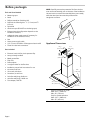 6
6
-
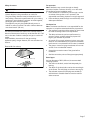 7
7
-
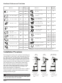 8
8
-
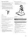 9
9
-
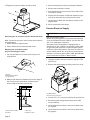 10
10
-
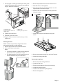 11
11
-
 12
12
-
 13
13
-
 14
14
-
 15
15
-
 16
16
-
 17
17
-
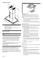 18
18
-
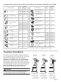 19
19
-
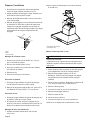 20
20
-
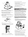 21
21
-
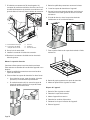 22
22
-
 23
23
-
 24
24
-
 25
25
-
 26
26
-
 27
27
-
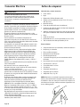 28
28
-
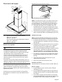 29
29
-
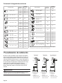 30
30
-
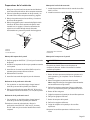 31
31
-
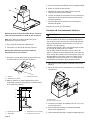 32
32
-
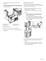 33
33
-
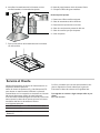 34
34
-
 35
35
-
 36
36


Bosch HCP56652UC Guía de instalación
- Tipo
- Guía de instalación
- Este manual también es adecuado para
en otros idiomas
- français: Bosch HCP56652UC Guide d'installation
- English: Bosch HCP56652UC Installation guide
Artículos relacionados
-
Bosch HCP30E52UC Guía de instalación
-
Bosch HCP30E51UC Guía de instalación
-
-
-
Bosch HCP36E51UC Guía de instalación
-
Bosch HUI56551UC/01 Guía de instalación
-
-
-