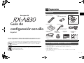
Yamaha RX-A830 Guía de instalación
- Categoría
- Receptores AV
- Tipo
- Guía de instalación
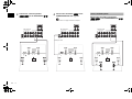
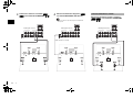
El Yamaha RX-A830 es un potente receptor AV de 7.2 canales con una variedad de características para mejorar tu experiencia de entretenimiento en casa. Con soporte para los últimos formatos de audio y video, incluyendo Dolby Atmos y 4K Ultra HD, el RX-A830 ofrece un sonido envolvente y una imagen nítida. También cuenta con transmisión inalámbrica de música a través de Bluetooth y Wi-Fi, lo que te permite reproducir tu música favorita desde tu smartphone, tablet u ordenador.
El Yamaha RX-A830 es un potente receptor AV de 7.2 canales con una variedad de características para mejorar tu experiencia de entretenimiento en casa. Con soporte para los últimos formatos de audio y video, incluyendo Dolby Atmos y 4K Ultra HD, el RX-A830 ofrece un sonido envolvente y una imagen nítida. También cuenta con transmisión inalámbrica de música a través de Bluetooth y Wi-Fi, lo que te permite reproducir tu música favorita desde tu smartphone, tablet u ordenador.


-
 1
1
-
 2
2
-
 3
3
-
 4
4
-
 5
5
-
 6
6
-
 7
7
-
 8
8
-
 9
9
-
 10
10
-
 11
11
-
 12
12
-
 13
13
-
 14
14
-
 15
15
-
 16
16
-
 17
17
-
 18
18


Yamaha RX-A830 Guía de instalación
- Categoría
- Receptores AV
- Tipo
- Guía de instalación
El Yamaha RX-A830 es un potente receptor AV de 7.2 canales con una variedad de características para mejorar tu experiencia de entretenimiento en casa. Con soporte para los últimos formatos de audio y video, incluyendo Dolby Atmos y 4K Ultra HD, el RX-A830 ofrece un sonido envolvente y una imagen nítida. También cuenta con transmisión inalámbrica de música a través de Bluetooth y Wi-Fi, lo que te permite reproducir tu música favorita desde tu smartphone, tablet u ordenador.
En otros idiomas
- English: Yamaha RX-A830 Installation guide