Genius SLIDY BIG SLIDY 115 Instrucciones de operación
- Categoría
- Abridor de puerta
- Tipo
- Instrucciones de operación

SLIDY - BIG SLIDY
115V
SLIDY - BIG SLIDY
115V

AVVERTENZE PER L’INSTALLATORE
OBBLIGHI GENERALI PER LA SICUREZZA
1) ATTENZIONE! È importante per la sicurezza delle persone seguire attentamente tutta
l’istruzione. Una errata installazione o un errato uso del prodotto può portare a gravi
danni alle persone.
2) Leggere attentamente le istruzioni prima di iniziare l’installazione del prodotto.
3) I materiali dell’imballaggio (plastica, polistirolo, ecc.) non devono essere lasciati alla
portata dei bambini in quanto potenziali fonti di pericolo.
4) Conservare le istruzioni per riferimenti futuri.
5) Questo prodotto è stato progettato e costruito esclusivamente per l’utilizzo indicato in
questa documentazione. Qualsiasi altro utilizzo non espressamente indicato potrebbe
pregiudicare l’integrità del prodotto e/o rappresentare fonte di pericolo.
6) GENIUS declina qualsiasi responsabilità derivata dall’uso improprio o diverso da quello
per cui l’automatismo è destinato.
7) Non installare l’apparecchio in atmosfera esplosiva: la presenza di gas o fumi infiam-
mabili costituisce un grave pericolo per la sicurezza.
8) Gli elementi costruttivi meccanici devono essere in accordo con quanto stabilito dalle
Norme EN 12604 e EN 12605.
Per i Paesi extra-CEE, oltre ai riferimenti normativi nazionali, per ottenere un livello di
sicurezza adeguato, devono essere seguite le Norme sopra riportate.
9) GENIUS non è responsabile dell’inosservanza della Buona Tecnica nella costruzione
delle chiusure da motorizzare, nonché delle deformazioni che dovessero intervenire
nell’utilizzo.
10) L’installazione deve essere effettuata nell’osservanza delle Norme EN 12453 e EN 12445.
Il livello di sicurezza dell’automazione deve essere C+D.
11) Prima di effettuare qualsiasi intervento sull’impianto, togliere l’alimentazione elettri-
ca e scollegare le batterie.
12) Prevedere sulla rete di alimentazione dell’automazione un interruttore onnipolare con
distanza d’apertura dei contatti uguale o superiore a 3 mm. È consigliabile l’uso di un
magnetotermico da 6A con interruzione onnipolare.
13) Verificare che a monte dell’impianto vi sia un interruttore differenziale con soglia da
0,03 A.
14) Verificare che l’impianto di terra sia realizzato a regola d’arte e collegarvi le parti
metalliche della chiusura.
15) L’automazione dispone di una sicurezza intrinseca antischiacciamento costituita da
un controllo di coppia. E' comunque necessario verificarne la sogli di intervento
secondo quanto previsto dalle Norme indicate al punto 10.
16) I dispositivi di sicurezza (norma EN 12978) permettono di proteggere eventuali aree di
pericolo da Rischi meccanici di movimento, come ad Es. schiacciamento,
convogliamento, cesoiamento.
17) Per ogni impianto è consigliato l’utilizzo di almeno una segnalazione luminosa nonché
di un cartello di segnalazione fissato adeguatamente sulla struttura dell’infisso, oltre ai
dispositivi citati al punto “16”.
18) GENIUS declina ogni responsabilità ai fini della sicurezza e del buon funzionamento
dell’automazione, in caso vengano utilizzati componenti dell’impianto non di produ-
zione GENIUS.
19) Per la manutenzione utilizzare esclusivamente parti originali GENIUS.
20) Non eseguire alcuna modifica sui componenti facenti parte del sistema d’automazio-
ne.
21) L’installatore deve fornire tutte le informazioni relative al funzionamento manuale del
sistema in caso di emergenza e consegnare all’Utente utilizzatore dell’impianto il
libretto d’avvertenze allegato al prodotto.
22) Non permettere ai bambini o persone di sostare nelle vicinanze del prodotto durante il
funzionamento.
23) Tenere fuori dalla portata dei bambini radiocomandi o qualsiasi altro datore di impulso,
per evitare che l’automazione possa essere azionata involontariamente.
24) Il transito tra le ante deve avvenire solo a cancello completamente aperto.
25) L’Utente utilizzatore deve astenersi da qualsiasi tentativo di riparazione o d’intervento
diretto e rivolgersi solo a personale qualificato.
26) Tutto quello che non è previsto espressamente in queste istruzioni non è permesso
IMPORTANT NOTICE FOR THE INSTALLER
GENERAL SAFETY REGULATIONS
1) ATTENTION! To ensure the safety of people, it is important that you read all the following
instructions. Incorrect installation or incorrect use of the product could cause serious
harm to people.
2) Carefully read the instructions before beginning to install the product.
3) Do not leave packing materials (plastic, polystyrene, etc.) within reach of children
as such materials are potential sources of danger.
4) Store these instructions for future reference.
5) This product was designed and built strictly for the use indicated in this documentation.
Any other use, not expressly indicated here, could compromise the good condition/
operation of the product and/or be a source of danger.
6) GENIUS declines all liability caused by improper use or use other than that for which the
automated system was intended.
7) Do not install the equipment in an explosive atmosphere: the presence of inflammable
gas or fumes is a serious danger to safety.
8) The mechanical parts must conform to the provisions of Standards EN 12604 and EN
12605.
For non-EU countries, to obtain an adequate level of safety, the Standards mentioned
above must be observed, in addition to national legal regulations.
9) GENIUS is not responsible for failure to observe Good Technique in the construction of
the closing elements to be motorised, or for any deformation that may occur during
use.
10) The installation must conform to Standards EN 12453 and EN 12445. The safety level of the
automated system must be C+D.
11) Before attempting any job on the system, cut out electrical power and disconnect the
batteries.
12) The mains power supply of the automated system must be fitted with an all-pole
switch with contact opening distance of 3mm or greater. Use of a 6A thermal breaker
with all-pole circuit break is recommended.
CONSIGNES POUR L'INSTALLATEUR
RÈGLES DE SÉCURITÉ
1) ATTENTION! Il est important, pour la sécurité des personnes, de suivre à la lettre toutes
les instructions. Une installation erronée ou un usage erroné du produit peut entraîner
de graves conséquences pour les personnes.
2) Lire attentivement les instructions avant d'installer le produit.
3) Les matériaux d'emballage (matière plastique, polystyrène, etc.) ne doivent pas être
laissés à la portée des enfants car ils constituent des sources potentielles de danger.
4) Conserver les instructions pour les références futures.
5) Ce produit a été conçu et construit exclusivement pour l'usage indiqué dans cette
documentation. Toute autre utilisation non expressément indiquée pourrait
compromettre l'intégrité du produit et/ou représenter une source de danger.
6) GENIUS décline toute responsabilité qui dériverait d'usage impropre ou différent de
celui auquel l'automatisme est destiné.
7) Ne pas installer l'appareil dans une atmosphère explosive: la présence de gaz ou de
fumées inflammables constitue un grave danger pour la sécurité.
8) Les composants mécaniques doivent répondre aux prescriptions des Normes EN 12604
et EN 12605.
Pour les Pays extra-CEE, l'obtention d'un niveau de sécurité approprié exige non
seulement le respect des normes nationales, mais également le respect des Normes
susmentionnées.
9) GENIUS n'est pas responsable du non-respect de la Bonne Technique dans la construction
des fermetures à motoriser, ni des déformations qui pourraient intervenir lors de
l'utilisation.
10) L'installation doit être effectuée conformément aux Normes EN 12453 et EN 12445. Le
niveau de sécurité de l'automatisme doit être C+D.
11) Couper l'alimentation électrique et déconnecter la batterie avant toute intervention
sur l'installation.
12) Prévoir, sur le secteur d'alimentation de l'automatisme, un interrupteur omnipolaire
avec une distance d'ouverture des contacts égale ou supérieure à 3 mm. On
recommande d'utiliser un magnétothermique de 6A avec interruption omnipolaire.
13) Vérifier qu'il y ait, en amont de l'installation, un interrupteur différentiel avec un seuil
de 0,03 A.
14) Vérifier que la mise à terre est réalisée selon les règles de l'art et y connecter les pièces
métalliques de la fermeture.
15) L'automatisme dispose d'une sécurité intrinsèque anti-écrasement, formée d'un
contrôle du couple. Il est toutefois nécessaire d'en vérifier le seuil d'intervention
suivant les prescriptions des Normes indiquées au point 10.
16) Les dispositifs de sécurité (norme EN 12978) permettent de protéger des zones
éventuellement dangereuses contre les Risques mécaniques du mouvement, comme
l'écrasement, l'acheminement, le cisaillement.
17) On recommande que toute installation soit doté au moins d'une signalisation
lumineuse, d'un panneau de signalisation fixé, de manière appropriée, sur la structure
de la fermeture, ainsi que des dispositifs cités au point “16”.
18) GENIUS décline toute responsabilité quant à la sécurité et au bon fonctionnement de
l'automatisme si les composants utilisés dans l'installation n'appartiennent pas à la
production GENIUS.
19) Utiliser exclusivement, pour l'entretien, des pièces GENIUS originales.
20) Ne jamais modifier les composants faisant partie du système d'automatisme.
21) L'installateur doit fournir toutes les informations relatives au fonctionnement manuel
du système en cas d'urgence et remettre à l'Usager qui utilise l'installation les
"Instructions pour l'Usager" fournies avec le produit.
22) Interdire aux enfants ou aux tiers de stationner près du produit durant le
fonctionnement.
23) Eloigner de la portée des enfants les radiocommandes ou tout autre générateur
d'impulsions, pour éviter tout actionnement involontaire de l'automatisme.
24) Le transit entre les vantaux ne doit avoir lieu que lorsque le portail est complètement
ouvert.
25) L'Usager qui utilise l'installation doit éviter toute tentative de réparation ou d'intervention
directe et s'adresser uniquement à un personnel qualifié.
26) Tout ce qui n'est pas prévu expressément dans ces instructions est interdit.
13) Make sure that a differential switch with threshold of 0.03 A is fitted upstream of the
system.
14) Make sure that the earthing system is perfectly constructed, and connect metal parts
of the means of the closure to it.
15) The automated system is supplied with an intrinsic anti-crushing safety device
consisting of a torque control. Nevertheless, its tripping threshold must be checked as
specified in the Standards indicated at point 10.
16) The safety devices (EN 12978 standard) protect any danger areas against mechanical
movement Risks, such as crushing, dragging, and shearing.
17) Use of at least one indicator-light is recommended for every system, as well as a
warning sign adequately secured to the frame structure, in addition to the devices
mentioned at point “16”.
18) GENIUS declines all liability as concerns safety and efficient operation of the automated
system, if system components not produced by GENIUS are used.
19) For maintenance, strictly use original parts by GENIUS.
20) Do not in any way modify the components of the automated system.
21) The installer shall supply all information concerning manual operation of the system
in case of an emergency, and shall hand over to the user the warnings handbook
supplied with the product.
22) Do not allow children or adults to stay near the product while it is operating.
23) Keep remote controls or other pulse generators away from children, to prevent the
automated system from being activated involuntarily.
24) Transit through the leaves is allowed only when the gate is fully open.
25) The user must not attempt any kind of repair or direct action whatever and contact
qualified personnel only.
26) Anything not expressly specified in these instructions is not permitted.

ITALIANO
1
DICHIARAZIONE CE DI CONFORMITÀ PER MACCHINE
(DIRETTIVA 98/37/CE)
Fabbricante: GENIUS S.p.A.
Indirizzo: Via Padre Elzi, 32 - 24050 - Grassobbio BERGAMO - ITALIA
Dichiara che: L'operatore mod. SLIDY-115 V / BIG SLIDY-115 V
• è costruito per essere incorporato in una macchina o per essere assemblato con altri macchinari per costituire una macchina ai
sensi della Direttiva 98/37/CE;
• è conforme ai requisiti essenziali di sicurezza delle seguenti altre direttive CEE:
73/23/CEE e successiva modifica 93/68/CEE.
89/336/CEE e successiva modifica 92/31/CEE e 93/68/CEE
inoltre dichiara che non è consentito mettere in servizio il macchinario fino a che la macchina in cui sarà incorporato o di cui
diverrà componente sia stata identificata e ne sia stata dichiarata la conformità alle condizioni della Direttiva 98/37/CE.
Grassobbio, 01-07-2005
L’amministratore delegato
D.Gianantoni
INDICE
DICHIARAZIONE CE DI CONFORMITÀ PER MACCHINE pag.1
DESCRIZIONE E CARATTERISTICHE TECNICHE pag.2
PREDISPOSIZIONI ELETTRICHE pag.2
INSTALLAZIONE DELL’AUTOMAZIONE pag.2
MESSA IN FUNZIONE pag.5
PROVA DELL'AUTOMAZIONE pag.5
MANUTENZIONE pag.5
FUNZIONAMENTO MANUALE pag.5
APPLICAZIONI PARTICOLARI pag.5
RIPARAZIONE pag.5

ITALIANO
2
1) Operatore con apparecchiatura elettrica incorporata
(prevedere apposita piastra di fondazione)
2) Fotocellule
3) Pulsante a chiave
4) Lampeggiatore
5) Ricevente
Note:
1) Per la messa in opera dei cavi elettrici utilizzare adeguati tubi
rigidi e/o flessibili
2) Separare sempre i cavi di collegamento degli accessori a
bassa tensione da quelli di alimentazione a 115 V~. Per evi-
tare qualsiasi interferenza utilizzare guaine separate
AUTOMAZIONE SLIDY - BIG SLIDY
L’automazione SLIDY per cancelli scorrevoli residenziali è un ope-
ratore elettromeccanico che trasmette il movimento all’anta
tramite un pignone accoppiato opportunamente ad una cre-
magliera fissata sul cancello.
Il sistema irreversibile garantisce il blocco meccanico quando il
motore non è in funzione e quindi non occorre installare alcuna
serratura. Un comodo sblocco rende manovrabile il cancello in
caso di black-out o disservizio.
Questo operatore è privo di frizione meccanica, quindi necessi-
ta di una apparecchiatura di comando con frizione elettroni-
ca.
Gli operatori SLIDY hanno l’apparecchiatura elettronica di co-
mando integrata nel corpo dell’operatore.
1. DESCRIZIONE E CARATTERISTICHE TECNICHE
Caratteristiche tecniche operatori
1 Carter di protezione
2 Coperchio per supporto
3 Supporto apparecchiatura elettronica
4 Apparecchiatura elettronica
5 Foro di passaggio cavi
6 Dispositivo di sblocco con serratura
7 Fori inferiori di fissaggio carter (n°4)
8 Asole di fissaggio operatore
9 Sensore
10 Pignone
11 Motore elettrico
12 Collegamento di messa a terra dell’operatore
2. PREDISPOSIZIONI ELETTRICHE (impianto standard)
3. INSTALLAZIONE DELL’AUTOMAZIONE
3.1. VERIFICHE PRELIMINARI
Per un corretto funzionamento dell’automazione la struttura del
cancello esistente, o da realizzare, deve presentare i seguenti
requisiti:
• peso del cancello non superiore a 500 Kg per il modello SLIDY
e 1000 Kg per il modello BIG SLIDY;
• struttura dell’anta robusta e rigida;
• superficie dell'anta liscia (priva di sporgenze);
• movimento regolare ed uniforme dell’anta, privo di attriti
durante tutta la corsa;
• assenza di oscillazioni laterali dell’anta;
• ottimo stato dei sistemi di scorrimento inferiore e superiore.
L’utilizzo di una guida a terra a gola arrotondata è preferibile
per ottenere degli attriti di scorrimento ridotti.
• presenza di solamente due ruote di scorrimento;
• presenza degli arresti meccanici di sicurezza per evitare pe-
ricoli di deragliamento del cancello; tali arresti devono essere
fissati saldamente al suolo o sulla guida a terra circa 40 mm
oltre la posizione di finecorsa.
• assenza di serrature meccaniche di chiusura.
Si raccomanda di effettuare gli eventuali interventi fabbrili pri-
ma d’installare l’automazione.
Lo stato della struttura influenza direttamente l’affidabilità e la
sicurezza dell’automazione.
3.2. INSTALLAZIONE DELL’OPERATORE
1) Assemblare la piastra di fondazione come da Fig.3.
2) Eseguire uno scavo per la piastra di fondazione come da fig.
4. La piastra di fondazione deve essere posizionata come da
fig. 5 (chiusura destra) o fig. 6 (chiusura sinistra) per garantire
il corretto ingranamento tra il pignone e la cremagliera.
Nota bene: È consigliabile collocare la piastra su un basamento
di cemento a circa 50 mm dal suolo (fig. 7).
3) Mettere in opera i tubi flessibili necessari per il passaggio dei
cavi di collegamento tra il motoriduttore, gli accessori e l’ali-
mentazione elettrica. I tubi flessibili devono uscire circa 3 cm
dal foro presente sulla piastra (fig. 4).
olledoM V511ydilS V511ydilSgiB
enoizatnemilA zH06~V511
atibrossaaznetoP W053W006
otnemibrossA A3A2.5
ocirtteleerotomnim/iriG 0041
otnupsiderotasnednoC V004/Fµ03V004/Fµ05
enoizudiridotroppaR 52:1
enongiP 61Z41Z
areilgamerC 4oludom
xamaippoC mN
81mN42
xamatnipS Nad54Nad07
otnemiglovva'llusenoizetorpomreT C°041
ozzilituidazneuqerF %03%04
etneibmaarutarepm
eT C°55+C°02-
erotarepooseP gK01gK11
enoizetorpidodarG 44PI
ollecnacxamoseP gK005gK0001
ollecnacàticoleV nim/m41n
im/m21
ollecnacxamazzehgnuL m51
Fig. 1
Fig. 2

ITALIANO
3
4) Murare perfettamente in piano la piastra.
5) Attendere che il cemento abbia fatto presa nello scavo.
6) Predisporre i cavi elettrici per il collegamento con gli acces-
sori e l’alimentazione elettrica (paragrafo 2). Per effettuare
agevolmente i collegamenti elettrici sull’apparecchiatura
elettronica fare fuoriuscire i cavi elettrici di circa 20 cm dal
foro della piastra di fondazione.
7) Fissare l’operatore sulla piastra di fondazione utilizzando le
viti e rondelle in dotazione come da fig. 8. Il posizionamento
dell’operatore è indicato nella fig. 7. Durante tale operazio-
ne fare passare i cavi elettrici attraverso l’apposito foro (fig.1-
rif.5) presente sulla base del corpo del motoriduttore.
8) Fare passare i cavi elettrici di collegamento attraverso l’ap-
posito foro presente sulla base del supporto dell’apparec-
chiatura (fig.1-rif.3) utilizzando il pressacavo in dotazione.
9) Eseguire i collegamenti elettrici all’apparecchiatura elettro-
nica di comando come da istruzioni dell'apparecchiatura
Importante :
1) Collegare il cavo di terra dell’impianto sulla posizione di fig.1-
rif.12.
2) L’operatore viene fornito per un’installazione che prevede,
vista dall’interno, la chiusura del cancello a destra dell’ope-
ratore. Nel caso di chiusura a sinistra è necessario invertire il
collegamento dei cavi collegati sui morsetti del Motore.
Nota bene: le quote indicate nelle figure sono espresse in mm.
3.3. MONTAGGIO DELLA CREMAGLIERA
1) Predisporre la cremagliera ( fornibile a richiesta ), con le viti TE
8 x 25 e i distanziali a saldare in dotazione, come da fig.9. Per
evitare di saldare sul cancello sono disponibili dei distanziali
passanti zincati con viti di fissaggio TE 8 x 50.
Nota bene: È consigliabile serrare le viti di fissaggio della
cremagliera nella parte superiore dell’asola. Tale posizione
consente di alzare la cremagliera quando nel tempo, il
cancello tenderà ad abbassarsi.
2) Sbloccare l’operatore (vedi paragrafo 6).
Fig. 3
Fig. 4
Fig. 5
Fig. 6
Fig. 7
Fig. 8

ITALIANO
4
3) Portare manualmente l’anta in posizione d’apertura.
4) Appoggiare sul pignone il primo elemento di cremagliera in
corrispondenza del primo distanziale (fig. 10).
5) Fissare l’elemento di cremagliera all’anta con un morsetto
(fig. 10).
6) Fare scorrere manualmente l’anta verso la chiusura fino ad
arrivare in corrispondenza del terzo distanziale della crema-
gliera, e fissarlo con un punto di saldatura.
7) Saldare definitivamente i tre distanziali sul cancello. Per fissa-
re correttamente gli altri elementi di cremagliera necessari
per arrivare in posizione di chiusura agire come segue:
8) Accostare un altro elemento di cremagliera all’ultimo fissato
utilizzando un pezzo di cremagliera di circa 150 mm per met-
tere in fase la dentatura dei due elementi (fig. 11).
9) Fare scorrere manualmente l’anta verso la chiusura fino ad
arrivare in corrispondenza del pignone con il terzo distanzia-
le dell’elemento da fissare (fig. 11).
Nota bene: Verificare che tutti gli elementi di cremagliera lavorino
sul centro dei denti del pignone. In caso contrario adattare
la posizione del motoriduttore.
10) Saldare i tre distanziali dell’elemento (fig. 10).
Attenzione:
a) Non saldare assolutamente gli elementi di cremagliera nè
ai distanziali, nè tra di loro.
b) Non utilizzare assolutamente grasso o altri prodotti lubrificanti
tra pignone e cremagliera.
11) Per ottenere il corretto gioco tra il pignone e la cremagliera
abbassare il motoriduttore di 1,5 mm agendo sui dadi di
supporto della piastra di fondazione (fig.12). Al termine di
tale regolazione serrare opportunamente i dadi di fissaggio
dell’operatore.
Attenzione : Nel caso di cancello di nuova costruzione verificare
tale gioco (fig.13) dopo alcuni mesi dall’installazione.
12) Verificare manualmente che il cancello sia libero di aprirsi
completamente e che il movimento dell’anta sia regolare e
privo di attriti.
3.4. POSIZIONAMENTO DEI MAGNETI DI FINECORSA
L’operatore è dotato di un finecorsa magnetico, che coman-
da l’arresto del moto del cancello nel momento in cui il magne-
te, fissato nella parte superiore della cremagliera, attiva il senso-
re. I magneti forniti con l’operatore sono appositamente
polarizzati ed azionano solo un contatto del sensore, il contatto
di chiusura o quello di apertura. Il magnete che aziona il con-
tatto di cancello aperto riporta raffigurato un lucchetto aper-
to, viceversa il magnete che attiva il contatto di cancello chiu-
so riporta il simbolo di lucchetto chiuso (vedi Fig.14).
Per posizionare correttamente i due magneti di finecorsa agire
come di seguito:
1) Assemblare i due magneti come indicato in figura 14.
Fig. 9
Fig. 10
Fig. 11
Fig. 12
Fig. 13
Fig. 14

ITALIANO
5
2) Predisporre l’operatore per il funzionamento manuale, vedi
capitolo 6, ed alimentare il sistema.
3) Portare manualmente il cancello in posizione d’apertura
lasciando circa 40 mm dall’arresto meccanico di apertura.
4) Far scorrere sulla cremagliera il magnete con il lucchetto
aperto nella direzione di apertura, vedi figura 15. Appena il
led relativo al finecorsa di apertura presente sulla scheda si
spegne far avanzare il magnete di altri 10 mm e fissarlo prov-
visoriamente con le apposite viti.
5) Ripetere le operazioni dal punto 3 per il magnete di chiusu-
ra.
6) Ribloccare il sistema (vedi paragrafo 6).
Importante: prima di inviare un’impulso assicurarsi che il
cancello non si possa muovere manualmente.
7) Comandare un ciclo completo per verificare il corretto fun-
zionamento dei finecorsa.
Attenzione:
- Per evitare danneggiamenti dell’operatore e/o interruzioni
del funzionamento dell’automazione è necessario lasciare
circa 40 mm dagli arresti meccanici di sicurezza.
- Controllare che a fine manovra, sia di apertura che di chiusura,
il rispettivo contatto rimanga attivato (led spento).
8) Apportare le opportune modifiche alla posizione dei ma-
gneti e fissarli definitivamente.
4. MESSA IN FUNZIONE
1) Programmare l’apparecchiatura elettronica secondo le pro-
prie esigenze come da istruzioni relative.
2) Alimentare il sistema e verificare lo stato dei leds come dalla
tabella riportata nelle istruzioni dell'apparecchiatura elet-
tronica.
3) Dopo aver eseguito la prova dell'automazione (par. 5), fissa-
re il carter di protezione sull'operatore utilizzando le viti in
dotazione come da fig. 16.
5. PROVA DELL'AUTOMAZIONE
Procedere alla verifica funzionale accurata dell'automazione
e di tutti gli accessori ad essa collegati.
Consegnare al Cliente la pagina "Guida per l'Utente" e illustrare
il corretto funzionamento e utilizzo dell'automazione.
6. FUNZIONAMENTO MANUALE
Nel caso sia necessario azionare manualmente il cancello a
causa di mancanza di corrente o disservizio dell’automazione,
è necessario agire sul dispositivo di sblocco (fig.1-rif.6) come se-
gue:
- Utilizzando una moneta ruotare in senso orario la serratura
sino al suo arresto (Fig.17 rif.1)
- Tirare la leva come indicato in fig. 17 rif.2
Per ripristinare il normale funzionamento agire come di seguito:
- Togliere alimentazione al sistema.
- Posizionare il cancello circa a metà della corsa di apertura
- Riportare in posizione la leva di sblocco;
- Utilizzando una moneta ruotare in senso antiorario la serratura
sino al suo arresto;
- Dare alimentazione al sistema.
Nota bene: al ripristino della tensione di alimentazione
comandare un ciclo di apertura completo.
Importante: prima di inviare un'impulso assicurarsi che il
cancello non si possa muovere manualmente.
7. APPLICAZIONI PARTICOLARI
Non sono previste applicazioni particolari.
8. MANUTENZIONE
Al fine d’assicurare nel tempo un corretto funzionamento ed un
costante livello di sicurezza è opportuno eseguire, con caden-
za semestrale, un controllo generale dell’impianto. Nel fascico-
lo “Guida per l’utente” è stato predisposto un modulo per la
registrazione degli interventi.
9. RIPARAZIONE
Per eventuali riparazioni rivolgersi ai Centri di Riparazione auto-
rizzati.
Fig. 16
Fig. 17
Fig. 15

ENGLISH
6
CE DECLARATION OF CONFORMITY FOR MACHINES
(DIRECTIVE 98/37/EC)
Manufacturer: GENIUS S.p.A.
Address: Via Padre Elzi, 32 - 24050 - Grassobbio BERGAMO - ITALY
Declares that: Operator model SLIDY-115 V / BIG SLIDY-115 V
• is built to be incorporate in a machine or to be assembled with other machinery to create a machine under the provisions of
Directive 98/37/EEC;
• conforms to the essential safety requirements of the other following EEC directives:
73/23/EEC and subsequent amendment 93/68/EEC.
89/336/EEC and subsequent amendment 92/31/EEC and 93/68/EEC
Furthermore, the manufacturer declares that the machinery must not be put into service until the machine into which it will be
incorporated or of which it will become a part has been identified and its conformity to the conditions of Directive 98/37/EC has
been declared.
Grassobbio, 01-07-2005
The Managing Director
D.Gianantoni
INDEX
CE DECLARATION OF CONFORMITY FOR MACHINES pag.6
DESCRIPTION AND TECHNICAL SPECIFICATIONS pag.7
ELECTRIC EQUIPMENT pag.7
INSTALLING THE AUTOMATED SYSTEM pag.7
AUTOMATED SYSTEM TEST pag.10
START-UP pag.10
MANUAL OPERATION pag.10
SPECIAL APPLICATIONS pag.10
MAINTENANCE pag.10
REPAIRS pag.10

ENGLISH
7
1) Operator with built-in electric equipment (supply a
suitable foundation plate)
2) Photocells
3) Key push-button
4) Flashing lamp
5) Receiver
Notes:
1) To lay cables, use adequate rigid and/or flexible tubes.
2) Always separate connection cables of low voltage
accessories from those operating at 115 V~. To avoid any
interference, use separate sheaths.
1 Protective housing
2 Cover for support
3 Control unit support
4 Control unit
5 Cable routing hole
6 Release device with lock
7 Lower holes for fastening the housing (4)
8 Operator securing slot
9 Sensor
10 Pinion
11 Electric motor
12 Operator earthing connection
SLIDY - BIG SLIDY AUTOMATED SYSTEM
The SLIDY automated system for residential sliding gates is an
electro-mechanical operator which transmits motion to the leaf
through a pinion gear suitably coupled to a rack fitted on the
gate.
The non-reversing system ensures mechanical locking when the
motor is not operating and, therefore, it is not necessary to install
any lock. A handy release device makes it possible to move the
gate in the event of a power cut or malfunction.
This operator has no mechanical clutch, and, therefore, requires
a control unit with electronic clutch.
SLIDY operators have the electronic control unit built into the
operator body.
1. DESCRIPTION AND TECHNICAL SPECIFICATIONS
Technical specifications of operators
2. ELECTRIC EQUIPMENT (standard system)
3. INSTALLING THE AUTOMATED SYSTEM
3.1. PRELIMINARY CHECKS
To ensure a correctly operating automated system, the structure
of the existing gate or gate to be built must satisfy the following
requirements:
• Weight of gate no greater than 500 kg for SLIDY model and
1000 kg for BIG SLIDY model;
• sturdy, rigid leaf structure;
• smooth leaf surface (without any projections);
• smooth, uniform leaf movement, without any friction during
the entire travel;
• no sideways leaf swings;
• top and bottom sliding systems must be in excellent condition.
It is preferable to use a ground-level guide with rounded
groove to obtain reduced sliding friction.
• only two sliding wheels;
• mechanical safety stops required to prevent the danger of
gate derailment; these stops must be firmly secured to the
ground or to the ground-level guide at about 2 cm beyond
the travel limit position
• no mechanical closing locks.
We advise you to carry out the metalwork jobs before installing
the automated system.
The condition of the structure directly influences the reliability
and safety of the automated system.
3.2. INSTALLING THE OPERATOR
1) Assemble the foundation plate as shown in Fig.3.
2) Dig a cavity for the foundation plate as shown in Fig. 4. The
foundation plate must be located as shown in Fig. 5 (right
closing) or Fig.6 (left closing) to ensure correct meshing between
rack and pinion.
NB.: We advise you to place the plate on a cement base about
50 cm off the ground (fig.7).
3) Lay the flexible tubes for routing the connection cables
between gearmotor, accessories and electrical power supply.
The flexible tubes must come out at about 3 cm from the hole
on the plate (fig.4).
ledoM V511ydilS V511ydilSgiB
ylppusrewoP zH06~V511
rewopdebrosbA W053W006
noitprosbA A3A2.5
mprrotomcirtcelE 0041
roticapactsurh
T V004/Fµ03V004/Fµ05
oitarnoitcudeR 52:1
noiniP 61Z41Z
kcaR 4oludom
euqrot.xaM mN81mN42
tsurhtxaM Nad54Nad07
gnidniwn
onoitcetorplamrehT C°041
ycneuqerfesU %03%04
erutarepmettneibmagnitarepO C°55+C°02-
thgiewrotarepO gK01gK11
ssa
lcnoitcetorP 44PI
thgiewetagxaM gK005gK0001
deepsetaG nim/m41nim/m21
htgneletagxaM m51
Fig. 1
Fig. 2

ENGLISH
8
4) Wall in the plate surface perfectly.
5) Wait for the cement to set in the cavity.
6) Lay the electrical cables for connection to the accessories
and the electrical power supply (paragraph 2). To facilitate
making the electrical connections on the control unit, make
the electrical cables come out at about 20 cm from the hole
on the foundation plate.
7) Secure the operator on the foundation plate, using the
supplied screws and washers as shown in Fig. 8. The operator’s
position is shown in Fig. 7. When positioning the operator, route
the electrical cables through the hole (fig.1-ref.5) on the base
of the gearmotor body.
8) Route the connecting electrical cables through the hole on
the base of the control unit’s support (fig.1-ref.3), using the
supplied cable gland.
9) Make the electrical connections to the electronic control
unit according to the instructions for the equipment.
Important :
1) Connect the earthing cable of the system to the position
shown in fig.1-ref.12.
2) The operator is supplied for installation with the gate closing
on the right of the operator (looking from the inside). If you
require left-hand closure, change over the connection of the
cables connected to the terminals of the Motor.
NB.: the dimensions in the figures are in mm.
3.3. INSTALLING THE RACK
1) Prepare the rack (supplied on request), with the TE 8 x 25
screws, and spacers to be welded (supplied), as shown in Fig.
9. To avoid having to weld on the gate, galvanised through-
spacers and TE 8 x 50 fixing screws are available.
NB.: We advise you to tighten the fixing screws of the rack on
the top end of the slot. This position will enable you to raise
the rack when the gate tends to lower through time.
2) Release the operator (see paragraph 6).
Fig. 3
Fig. 4
Fig. 5
Fig. 6
Fig. 7
Fig. 8

ENGLISH
9
3) Manually move the leaf to opening position.
4) Lay the first element of the rack on the pinion, on the first
spacer (fig.10).
5) Secure the rack element to the leaf with a clamp (fig.10).
6) Manually slide the leaf toward the closing point until you
reach the rack’s third spacer, and fix it with a weld spot.
7) Definitively weld the three spacers on the gate. Procedure
for correctly fixing the other rack elements required to reach
the closing position:
8) Bring near another rack element to the last fixed element,
using a piece of rack of about 150 mm to synchronise the
teeth with the two elements (fig.11).
9) Manually slide the leaf toward the closing point until you
reach the pinion with the third spacer of the element to be
secured (fig.11).
NB.: Make sure that all the rack elements work on the centre of
the pinion’s teeth. Otherwise, adapt the gearmotor’s position.
10) Weld the element’s three spacers (fig.10)
Attention:
a) Do not, on any account, weld the rack elements either to the
spacers or to each other.
b) Do not, on any account, use grease or other lubricants
between rack and pinion.
11) To obtain correct play between rack and pinion, lower the
gearmotor by 1.5 mm, using the nuts supporting the
foundation plate (fig.12). When you have finished adjusting,
correctly tighten the operator securing nuts.
Attention: If the gate was recently built, check this play (fig.13)
a few months after installation.
12) Manually check if the gate is free to open completely and
if leaf movement is good and friction- free.
3.4. POSITIONING THE LIMIT-SWITCH MAGNETS
The operator has a magnetic limit-switch, which commands
gate motion to stop when the magnet, which is secured to the
upper part of the rack, activates the sensor. The magnets
supplied with the operator are specifically polarised and activate
only one of the sensor’s contacts: the closing or opening contact.
The magnet activating the open gate contact bears an open
padlock symbol, and, vice versa, the magnet activating the
closed gate contact bears the closed padlock symbol (see Fig.
14).
Procedure for correct positioning of the two limit-switch magnets:
1) Assemble the two magnets as shown in Fig. 14.
Fig. 9
Fig. 10
Fig. 11
Fig. 12
Fig. 13
Fig. 14

ENGLISH
10
2) Set the operator to manual mode operation - see chapter 6
- and power up the system.
3) Manually take the gate to opening position, leaving about
40 mm from the opening mechanical stop.
4) Allow the magnet, with the padlock open in opening
direction, to slide on the rack - see figure 15. As soon as the
LED on the board, referring to the opening limit-switch, goes
OFF, take the magnet forward by another 10 mm and fasten
it provisionally with the appropriate screws.
5) Repeat the operations from point 3 for the closing magnet.
6) Re-lock the system (see paragraph 6).
Important : before sending a pulse, make sure that the gate
cannot be moved manually.
7) Command a complete cycle to check if the limit-switches
are operating correctly.
Attention:
- To avoid damaging the operator and/or interrupting operation
of the automated system, leave a distance of about 40 mm
from the safety mechanical stops.
- Make sure that at the end of both the opening and closing
manoeuvre, the relevant contact stays active (LED OFF).
8) Change the position of the magnets as necessary and secure
them definitively.
4. START-UP
1) Program the control unit according to your needs, as per
relevant instructions.
2) Power up the system and check the condition of the LEDs
according to the table in the control unit instructions.
3) After testing the automated system (par.5), secure the
protective housing on the operator, using the supplied screws
as shown in Fig. 16.
5. AUTOMATED SYSTEM TEST
Check operating efficiency of the automated system and all
accessories connected to it.
Hand the customer the “User’s Guide” page and explain how
the automated system operates correctly and how it should be
used.
6. MANUAL OPERATION
If the gate has to be moved manually due to a power cut or
malfunction of the automated system, use the release device
(fig.1-ref.6) as follows:
- Using a coin, turn the lock clockwise until it stops (Fig.17 ref.1).
- Pull the lever as shown in Fig. 17 ref.2.
Procedure for restoring normal operation:
- Cut power to the system.
- Position the gate at about halfway of opening travel
- Take the release lever back into its position;
- Using a coin, turn the lock anti-clockwise until it stops;
- Restore power to the system.
NB.: when power is restored, command another complete
opening cycle.
Important : before sending a pulse, make sure that the gate
cannot be moved manually.
7. SPECIAL APPLICATIONS
There are no special applications.
8. MAINTENANCE
To ensure correct long-term operation and a constant level of
safety, we advise you to generally control the system every 6
months. In the “User’s Guide” booklet, there is a form for recording
jobs.
9. REPAIRS
For any repairs, contact the authorised Repair Centres.
Fig. 15
Fig. 16
Fig. 17

FRANÇAIS
11
DÉCLARATION CE DE CONFORMITÉ POUR MACHINES
(DIRECTIVE 98/37/CE)
Fabricant: GENIUS S.p.A.
Adresse: Via Padre Elzi, 32 - 24050 - Grassobbio BERGAMO - ITALIE
Déclare que: L'opérateur mod. SLIDY-115 V / BIG SLIDY-115 V
• est construit pour être incorporé à la machine ou pour être assemblé à d'autres machines pour constituer une machine conforme
à la Directive 98/37/CE;
• est conforme aux exigences essentielles de sécurité des autres directives CEE:
73/23/CEE et modification successive 93/68/CEE.
89/336/CEE et modification successive 92/31/CEE et 93/68/CEE
Il déclare, en outre, qu'il est interdit de mettre en service l'appareillage jusqu'à ce que la machine à laquelle il sera incorporé ou
dont il deviendra un composant ait été identifiée et jusqu'à ce que la conformité aux conditions de la Directive 98/37/CE en ait
été déclarée.
Grassobbio, le 01-07-2005
L'Administrateur Délégué
D.Gianantoni
INDEX
DÉCLARATION CE DE CONFORMITÉ POUR MACHINES pag.11
DESCRIPTION ET CARACTÉRISTIQUES TECHNIQUES pag.12
PRÉDISPOSITIONS ÉLECTRIQUES pag.12
INSTALLATION DE L’AUTOMATISME pag.12
ESSAI DE L’AUTOMATISME pag.15
MISE EN FONCTION pag.15
FONCTIONNEMENT MANUEL pag.15
APPLICATIONS PARTICULIÈRES pag.15
RÉPARATION pag.15
ENTRETIEN pag.15

FRANÇAIS
12
1) Opérateur avec appareillage électrique incorporé
(prévoir une plaque de fondation spécifique)
2) Photocellule
3) Bouton-poussoir à clé
4) Lampe clignotante
5) Récepteur
Remarques:
1) Utiliser des tuyaux rigides et/ou flexibles pour la pose des
câbles électriques
2) Toujours séparer les câbles d'alimentation à 115V~ des câbles
de raccordement des accessoires à basse tension. Pour éviter
les interférences, on recommande d'utiliser des gaines
séparées.
1 Carter de protection
2 Couvercle pour support
3 Support armoire électronique
4 Armoire électronique
5 Trou de passage des câbles
6 Dispositif de déverrouillage avec serrure
7 Trous inférieurs de fixation du carter (4)
8 Rainures de fixation de l'opérateur
9 Capteur
10 Pignon
11 Moteur électrique
12 Connexion de mise à la terre de l'opérateur
AUTOMATISME SLIDY - BIG SLIDY
L’automatisme SLIDY pour portails coulissants domestiques est
un opérateur électromécanique qui transmet le mouvement
au vantail par l’intermédiaire d’un pignon accouplé à une
crémaillère fixée sur le portail.
Le système irréversible garantit le blocage mécanique quand le
moteur n’est pas en fonction, il n’est donc pas nécessaire
d’installer de serrure. Un déverrouillage pratique permet de
manœuvrer le portail en cas de coupure de courant ou de
dysfonctionnement.
Cet opérateur est sans embrayage mécanique, il exige donc
une armoire de manœuvre à embrayage électronique.
L’armoire électronique de manœuvre des opérateurs SLIDY est
intégrée au corps de l’opérateur.
1. DESCRIPTION ET CARACTÉRISTIQUES TECHNIQUES
Caractéristiques techniques des opérateurs
2. PRÉDISPOSITIONS ÉLECTRIQUES (installation standard)
3. INSTALLATION DE L’AUTOMATISME
3.1. VÉRIFICATIONS PRÉLIMINAIRES
Pour un fonctionnement correct de l’automatisme, la structure
du portail existant, ou à réaliser, doit réunir les conditions suivantes:
• vantail jusqu'à un poids de 500 kg pour le modèle SLIDY et
jusqu'à 1 000 kg pour le modèle BIG SLIDY;
• structure du vantail solide et rigide;
• surface lisse du vantail (sans dépassements)
• mouvement régulier et uniforme du vantail, sans frottements
durant toute la course;
• absence d’oscillations latérales du vantail;
• excellent état des systèmes de coulissement inférieur et
supérieur. Il est préférable d’utiliser un rail au sol à gorge arrondie
pour réduire les frottements dus au coulissement.
• présence de deux roues de coulissement seulement;
• présence d’arrêts mécaniques de sécurité pour éviter les risques
de déraillement du portail; fixer solidement ces arrêts au sol
ou au rail sur le sol environ 2 cm au-delà de la position de fin
de course.
• absence de serrures mécaniques de fermeture.
On recommande d’effectuer les interventions de forge avant
d’installer l’automatisme.
L’état de la structure du portail influence directement la fiabilité
et la sécurité de l’automatisme.
3.2. INSTALLATION DE L’OPÉRATEUR
1) Assembler la plaque de fondation d’après la Fig.3.
2) Creuser un trou pour la plaque de fondation d’après la Fig. 4.
Positionner la plaque de fondation d’après la Fig. 5 (fermeture
à droite) ou la fig. 6 (fermeture à gauche) pour garantir
l’engrènement entre le pignon et la crémaillère.
Nota bene: On recommande de placer la plaque sur un socle
en béton à environ 50 mm du sol (fig. 7).
3) Poser les tuyaux flexibles nécessaires pour le passage des
câbles de connexion entre le motoréducteur, les accessoires
et l’alimentation électrique. Les tuyaux flexibles doivent sortir
d’environ 3 cm par le trou de la plaque (fig. 4).
elèdoM V511ydilS
ydilSgiB
V511
noitatnemilA zH06~V511
eébrosbaecnassiuP W053W006
noitprosbA A3A2.5
euqirtceléruetomnim/sruoT 0041
egarramédedruetasnednoC V004/Fµ03V004/Fµ05
noitcudéredtroppaR 52:1
nongiP 61Z41Z
erèlliamérC 4oludom
ixamelpuoC
mN81mN42
ixameéssuoP Nad54Nad07
tnemeluorne'lruseuqimrehtnoitcetorP C°041
noitasilitu'decneuqérF %03%04
noitasi
litu'derutarépmeT C°55+C°02-
ruetaréposdioP gK01gK11
noitcetorpedérgeD 44PI
liatropixamsdioP gK005gK0001
liatro
pessetiV nim/m41nim/m21
liatropixamrueugnoL m51
Fig. 1
Fig. 2

FRANÇAIS
13
4) Sceller la plaque parfaitement à plat.
5) Attendre que le béton ait pris dans le trou.
6) Prédisposer les câbles électriques pour la connexion avec les
accessoires et l’alimentation électrique (paragraphe 2). Pour
réaliser facilement les connexions électriques sur l’armoire
électronique, faire sortir les câbles électriques d’environ 20
cm par le trou de la plaque de fondation.
7) Fixer l’opérateur sur la plaque de fondation en utilisant les vis
et les rondelles fournies d’après la Fig. 8. Le positionnement
de l’opérateur est indiqué dans la fig. 7. Durant cette
opération, faire passer les câbles électriques à travers le trou
spécifique (fig.1-réf.5) présent sur la base du corps du
motoréducteur.
8) Faire passer les câbles électriques de connexion à travers le
trou spécifique sur la base du support de l’ armoire (fig.1-
réf.3) en utilisant le serre-câble fourni.
9) Réaliser les connexions électriques à l’armoire électronique
de manœuvre d’après les instructions de l’armoire.
Important:
1) Connecter le câble de terre de l’installation à l’endroit illustrée
dans la fig.1-réf.12.
2) L’opérateur est fourni pour une installation qui prévoit, vue
de l’intérieur, la fermeture du portail à la droite de l’opérateur.
En cas de fermeture à gauche, inverser la connexion des
câbles branchés sur les bornes du Moteur.
Nota bene: Les cotes indiquées dans les figures sont exprimées
en mm.
3.3. MONTAGE DE LA CRÉMAILLÈRE
1) Prédisposer la crémaillère (fournie sur demande), avec les vis
TE 8 x 25 et les entretoises à souder fournies, d’après la Fig.9.
Pour éviter de souder sur le portail, on dispose d’entretoises
passantes galvanisées avec des vis de fixation TE 8 x 50.
Nota bene: On recommande de serrer les vis de fixation de la
crémaillère dans la partie supérieure de la rainure. Cette
position permet de soulever la crémaillère lorsque le portail
se sera abaissé avec le temps.
2) Déverrouiller l’opérateur (voir paragraphe 6).
Fig. 3
Fig. 4
Fig. 5
Fig. 6
Fig. 7
Fig. 8

FRANÇAIS
14
3) Amener manuellement le vantail en position d’ouverture.
4) Poser sur le pignon le premier élément de la crémaillère au
niveau de la première entretoise (fig. 10).
5) Fixer l’élément de crémaillère au vantail avec un étau (fig.
10).
6) Faire coulisser manuellement le vantail vers la fermeture
jusqu’au niveau de la troisième entretoise de la crémaillère,
et la fixer avec un point de soudure.
7) Souder définitivement les trois entretoises sur le portail. Pour
fixer correctement les autres éléments de la crémaillère
nécessaires pour arriver en position de fermeture, agir comme
suit:
8) Approcher un autre élément de la crémaillère du dernier
qu’on a fixé en utilisant un morceau de crémaillère d’environ
150 mm pour mettre en phase la denture des deux éléments
(fig. 11).
9) Faire coulisser manuellement le vantail vers la fermeture
jusqu’au niveau du pignon avec la troisième entretoise de
l’élément à fixer (fig. 11).
Nota bene: Vérifier que tous les éléments de la crémaillère
travaillent au centre des dents du pignon. Dans le cas
contraire, adapter la position du motoréducteur.
10) Souder les trois entretoises de l’élément (fig. 10).
Attention:
a) Ne jamais souder les éléments de la crémaillère ni aux
entretoises, ni entre eux.
b) Ne jamais utiliser de graisse ou d’autres produits lubrifiants
entre le pignon et la crémaillère.
11) Pour obtenir le bon jeu entre le pignon et la crémaillère,
abaisser le motoréducteur de 1,5 mm en agissant sur les écrous
de support de la plaque de fondation (fig.12). Au terme de
ce réglage, serrer opportunément les écrous de fixation de
l’opérateur.
Attention : Si le portail est neuf, vérifier ce jeu (fig.13) quelques
mois après l’installation.
12) Vérifier manuellement que le portail est libre de s’ouvrir
complètement et que le mouvement du vantail est régulier
et sans frottements.
3.4. POSITIONNEMENT DES AIMANTS DE FIN DE COURSE
L’opérateur est doté d’un fin de course magnétique qui
commande l’arrêt du mouvement du portail au moment où
l’aimant, fixé dans la partie supérieure de la crémaillère, active
le capteur. Les aimants fournis avec l’opérateur sont
spécialement polarisés et actionnent uniquement un contact
du capteur, le contact de fermeture ou le contact d’ouverture.
Sur l’aimant qui actionne le contact de portail ouvert, on a
représenté un cadenas ouvert, vice versa, sur l’aimant qui active
le contact de portail fermé, on a représenté un cadenas fermé
(voir Fig.14).
Pour positionner correctement les deux aimants de fin de course,
procéder comme suit:
1) Assembler les deux aimants d’après la figure 14.
Fig. 9
Fig. 10
Fig. 11
Fig. 12
Fig. 13
Fig. 14

FRANÇAIS
15
2) Disposer l’opérateur pour le fonctionnement manuel, voir
chapitre 6, et alimenter le système.
3) Amener manuellement le portail en position d’ouverture en
laissant environ 40 mm à partir de l’arrêt mécanique d’ou-
verture.
4) Faire coulisser sur la crémaillère l’aimant avec le cadenas
ouvert dans la direction d’ouverture, voir figure 15. Dès que la
LED présente sur la carte et relative au fin de course d’ouver-
ture s’éteint, faire avancer l’aimant de 10 mm
supplémentaires et le fixer provisoirement avec des vis
spéciales.
5) Répéter les opérations à partir du point 3 pour l’aimant de
fermeture.
6) Bloquer de nouveau le système (voir paragraphe 6).
Important: avant d’envoyer une impulsion, s’assurer que le
portail ne peut pas être actionné manuellement.
7) Commander un cycle complet pour vérifier le
fonctionnement correct des fins de course.
Attention:
- Pour éviter d’endommager l’opérateur et/ou d’interrompre le
fonctionnement de l’automatisme, laisser environ 40 mm à
partir des arrêts mécaniques de sécurité.
- Contrôler qu’à la fin de la manœuvre, aussi bien d’ouverture
que de fermeture, le contact respectif reste activé (LED
éteinte).
8) Modifier si nécessaire la position des aimants et les fixer
définitivement.
4. MISE EN FONCTION
1) Programmer l’armoire électronique suivant les exigences
propres en suivant les instructions correspondantes.
2) Alimenter le système et vérifier l’état des LEDs en consultant le
tableau figurant dans les instructions de l’armoire
électronique.
3) Après avoir réalisé l’essai de l’automatisme (par. 5), fixer le
carter de protection sur l’opérateur en utilisant les vis fournies
d’après la Fig. 16.
5. ESSAI DE L’AUTOMATISME
Procéder à la vérification fonctionnelle minutieuse de
l’automatisme et de tous les accessoires connectés.
Remettre au Client la page “Instructions pour l’Utilisateur” puis
illustrer le fonctionnement correct et l’utilisation de l’automatisme.
6. FONCTIONNEMENT MANUEL
S’il faut actionner le portail manuellement en raison d’une
coupure de courant ou d’un dysfonctionnement de
l’automatisme, agir sur le dispositif de déverrouillage (fig.1-réf.6)
comme suit:
- Avec une pièce de monnaie, tourner la serrure en sens horaire
jusqu’à son arrêt (Fig.17 réf.1)
- Tirer le levier d’après la fig. 17 réf.2
Pour rétablir le fonctionnement normal, procéder comme suit:
- Mettre le système hors tension.
- Positionner le portail environ à la moitié de la course
d’ouverture
- Remettre le levier de déverrouillage en position;
- Avec une pièce de monnaie, tourner la serrure en sens
horaire jusqu’à son arrêt;
- Remettre le système sous tension.
Nota bene: au retour de la tension d’alimentation, commander
un cycle complet d’ouverture.
Important: avant d’envoyer une impulsion, s’assurer que le
portail ne peut pas être actionné manuellement.
7. APPLICATIONS PARTICULIÈRES
Aucune application particulière n’a été prévue.
8. ENTRETIEN
Pour assurer un fonctionnement correct dans le temps et un
niveau de sécurité constant, effectuer tous les six mois un contrôle
général de l’installation. Dans le livret “Instructions pour
l’Utilisateur” se trouve un formulaire pour l’enregistrement des
interventions.
9. RÉPARATION
Pour toute réparation éventuelle, s’adresser aux Centres de
Réparation agréés.
Fig. 15
Fig. 16
Fig. 17

ESPAÑOL
16
ÍNDICE
DECLARACIÓN CE DE CONFORMIDAD PARA MÁQUINAS pag.16
DESCRIPCIÓN Y CARACTERÍSTICAS TÉCNICAS pag.17
PREDISPOSICIONES ELÉCTRICAS pag.17
INSTALACIÓN DE LA AUTOMACIÓN pag.17
PUESTA EN FUNCIONAMIENTO pag.20
PRUEBA DE LA AUTOMACIÓN pag.20
FUNCIONAMIENTO MANUAL pag.20
APLICACIONES ESPECIALES pag.20
MANTENIMIENTO pag.20
REPARACIÓN pag.20
DECLARACIÓN CE DE CONFORMIDAD PARA MÁQUINAS
(DIRECTIVA 98/37/CE)
Fabricante: GENIUS S.p.A.
Dirección: Via Padre Elzi, 32 - 24050 - Grassobbio BERGAMO - ITALIA
Declara que: El operador mod. SLIDY-115 V / BIG SLIDY-115 V
• ha sido fabricado para ser incorporado en una máquina o para ser ensamblado con otras maquinarias para construir una
máquina de conformidad con la Directiva 98/37/CE;
• cumple con los requisitos esenciales de seguridad de las siguientes directivas CEE:
73/23/CEE y sucesiva modificación 93/68/CEE.
89/336/CEE y sucesiva modificación 92/31/CEE y 93/68/CEE
asimismo declara que no está permitido poner en funcionamiento la maquinaria hasta que la máquina en la que deberá
incorporarse o de la cual será un componente haya sido identificada y se haya declarado su conformidad con las condiciones
de la Directiva 98/37/CE.
Grassobbio, 01-07-2005
El Administrador Delegado
D.Gianantoni

ESPAÑOL
17
1) Operador con equipo eléctrico incorporado
(prever una específica placa de cimentación)
2) Fotocélulas
3) Pulsador de llave
4) Destellador
5) Receptor
Notas:
1) Para tender los cables eléctricos, utilice tubos rígidos y/o
flexibles adecuados.
2) No deje que los cables de conexión de los accesorios a baja
tensión se toquen con los de la alimentación de 115V~. Para
evitar cualquier interferencia utilice vainas separadas.
1 Cárter de protección
2 Tapa para soporte
3 Soporte equipo electrónico
4 Equipo electrónico
5 Orificio para el paso de cables
6 Dispositivo de desbloqueo con cerradura
7 Orificios inferiores de fijación del cárter (n°4)
8 Ranuras de fijación operador
9 Sensor
10 Piñón
11 Motor eléctrico
12 Conexión de puesta a tierra del operador
AUTOMACIÓN SLIDY - BIG SLIDY
La automación SLIDY para cancelas correderas residenciales
es un operador electromecánico que transmite el movimiento
a la hoja por medio de un piñón adecuadamente acoplado
a una cremallera fijada en la cancela.
El sistema irreversible garantiza el bloqueo mecánico cuando el
motor no está en funcionamiento, por lo que no es necesario
instalar cerradura alguna. Un cómodo sistema de desbloqueo
permite maniobrar la cancela en caso de falta de alimentación
eléctrica o de avería.
Este operador no tiene embrague mecánico, por lo que requiere
un equipo de mando con embrague electrónico.
Los operadores SLIDY tienen el equipo electrónico de mando
incorporado en el cuerpo del operador.
1. DESCRIPCIÓN Y CARACTERÍSTICAS TÉCNICAS
Características técnicas de los operadores
2. PREDISPOSICIONES ELÉCTRICAS (equipo estándar)
3. INSTALACIÓN DE LA AUTOMACIÓN
3.1. COMPROBACIONES PRELIMINARES
Para que la automación funcione correctamente, la estructura
de la cancela existente, o de la que se tenga que realizar, tiene
que presentar los siguientes requisitos:
• Peso de la cancela no superior a 500 kg para el modelo SLIDY
y a 1000 kg para el modelo BIG SLIDY.
• Estructura de la hoja robusta y rígida.
• Superficie de la hoja lisa (sin resaltes).
• Movimiento regular y uniforme de la hoja, sin rozamientos
durante toda la carrera.
• Falta de oscilaciones laterales de la hoja.
• Excelente estado de los sistemas de deslizamiento inferior y
superior. Es aconsejable usar una guía de tierra de garganta
redondeada a fin de reducir los roces en el deslizamiento.
• Presencia de sólo dos ruedas de deslizamiento.
• Presencia de los bloqueos mecánicos de seguridad para
evitar peligros de descarrilamiento de la cancela; dichos
bloqueos deben fijarse fuertemente al suelo o la guía de
tierra, a unos 2 cm más allá de la posición de final de carrera.
• Falta de cerraduras mecánicas de cierre.
Se aconseja efectuar las posibles intervenciones de fábrica antes
de instalar la automación.
El estado de la estructura influye directamente en la fiabilidad
y seguridad de la automación.
3.2. INSTALACIÓN DEL OPERADOR
1) Ensamble la placa de cimentación tal y como se indica en
la fig.3.
2) Realice una excavación para colocar la placa de
cimentación como se indica en la fig. 4. La placa de
cimentación debe colocarse como se indica en la fig. 5 (cierre
derecho) o en la fig. 6 (cierre izquierdo) para garantizar el
correcto engranaje entre el piñón y la cremallera.
Nota: Es aconsejable colocar la placa sobre una base de
cemento a unos 50 mm del suelo (fig.7).
3) Coloque los tubos flexibles necesarios para el paso de los
cables de conexión entre el motorreductor, los accesorios y
la alimentación eléctrica. Los tubos flexibles deben salir unos
3 cm por el orificio presente en la placa (fig.4).
oledoM V511ydilS V511ydilSgiB
nóicatnemilA zH06~V511
adibrosbaaicnetoP W053W006
nóicrosbA A3A2.5
ocirtcélerotom.m.p.R 0041
euqnar
raedrodasnednoC V004/Fµ03V004/Fµ05
nóiccuderednóicaleR 52:1
nóñiP 61Z41Z
arellamerC 4oludom
.xámraP mN81mN42
.xáme
jupmE Nad54Nad07
odaniboblenenóiccetorpomreT C°041
nóicazilituedaicneucerF %03%04
etneibmaarutarepmeT C°55+C°0
2-
rodarepooseP gK01gK11
nóiccetorpedodarG 44PI
alecnacaledomixámoseP gK005gK0001
alecnacaleddadicoleV nim/m41ni
m/m21
alecnacaledamixámdutignoL m51
Fig. 1
Fig. 2

ESPAÑOL
18
4) Cimente la placa de modo perfectamente horizontal.
5) Espere a que el cemento haya fraguado en la excavación.
6) Coloque los cables eléctricos para la conexión con los
accesorios y la alimentación eléctrica (párrafo 2). Para
efectuar fácilmente las conexiones eléctricas en el equipo
electrónico, los cables eléctricos deben salir unos 20 cm por
el orificio de la placa de cimentación.
7) Fije el operador sobre la placa de cimentación utilizando los
tornillos y las arandelas suministradas en dotación, tal y como
se indica en la fig. 8. El posicionamiento del operador está
indicado en la fig. 7. Durante dicha operación, pase los
cables eléctricos a través del correspondiente orificio (fig.1-
ref.5) presente en la base del cuerpo del motorreductor.
8) Pase los cables eléctricos de conexión a través del
correspondiente orificio presente en la base del soporte del
equipo (fig.1-ref.3) utilizando el sujeta-cables suministrado en
dotación.
9) Realice las conexiones eléctricas al equipo electrónico de
mando siguiendo las instrucciones del equipo.
Importante :
1) Conecte el cable de tierra del equipo en la posición indicada
en la fig.1-ref.12.
2) El operador se entrega preparado para una instalación
que prevé, vista desde el interior, el cierre de la cancela a la
derecha del operador. En caso de cierre a la izquierda hay
que invertir la conexión de los cables conectados en los
bornes del motor.
Nota: las cuotas indicadas en las figuras están expresadas en
mm.
3.3. MONTAJE DE LA CREMALLERA
1) Coloque la cremallera (que se suministra bajo pedido), con
los tornillos CH 8 x 25 y los distanciadores para soldar
suministrados en dotación, como se indica en la fig.9. Para
evitar soldar en la cancela, están disponibles distanciadores
pasantes galvanizados con tornillos de fijación CH 8 x 50.
Nota: Es aconsejable apretar los tornillos de fijación de la
cremallera en la parte superior de la ranura. Dicha posición
permite subir la cremallera cuando, con el paso del tiempo,
la cancela tienda a bajarse.
2) Desbloquee el operador (véase párrafo 6).
Fig. 3
Fig. 4
Fig. 5
Fig. 6
Fig. 7
Fig. 8

ESPAÑOL
19
3) Coloque manualmente la hoja en posición de apertura.
4) Apoye sobre el piñón el primer elemento de cremallera en
coincidencia con el primer distanciador (fig.10).
5) Fije el elemento de cremallera a la hoja con una grapa
(fig.10).
6) Deslice manualmente la hoja hacia el cierre, hasta llegar al
tercer distanciador de la cremallera, y fíjelo con un punto de
soldadura.
7) Suelde definitivamente los tres distanciadores en la cancela.
Para fijar correctamente los restantes elementos de cremallera,
necesarios para llegar a la posición de cierre, proceda del
siguiente modo:
8) Acerque otro elemento de cremallera al último fijado,
utilizando un trozo de cremallera de unos 150 mm para poner
en fase el dentado de los dos elementos (fig. 11).
9) Deslice manualmente la hoja hacia el cierre, hasta llegar al
piñón con el tercer distanciador del elemento que se ha de
fijar (fig. 11).
Nota: Compruebe que todos los elementos de cremallera
trabajen en el centro de los dientes del piñón. De no ser así,
adapte la posición del motorreductor.
10) Suelde los tres distanciadores del elemento (fig.10).
Atención:
a) No suelde absolutamente los elementos de cremallera, ni a
los distanciadores ni entre sí.
b) No utilice por ningún motivo grasa u otros productos
lubricantes entre el piñón y la cremallera.
11) Para obtener el juego correcto entre el piñón y la cremallera,
baje el motorreductor 1,5 mm por medio de las tuercas de
soporte de la placa de cimentación (fig.12). Una vez
finalizada dicha regulación, apriete adecuadamente las
tuercas de fijación del operador.
Atención: Si la cancela fuera nueva, compruebe dicho juego
(fig.13) transcurridos algunos meses de la instalación.
12) Compruebe manualmente que la cancela pueda abrirse
completamente y que el movimiento de la hoja sea regular
y sin rozamientos.
3.4. COLOCACIÓN DE LOS IMANES DE FINAL DE CARRERA
El operador está provisto de un final de carrera magnético que
manda la parada del movimiento de la cancela cuando el
imán, fijado en la parte superior de la cremallera, activa el
sensor. Los imanes suministrados con el operador están
expresamente polarizados y sólo accionan un contacto del
sensor, el contacto de cierre o el de apertura. El imán que
acciona el contacto de cancela abierta lleva el símbolo de un
candado abierto, mientras que el imán que activa el contacto
de cancela cerrada lleva el símbolo de un candado cerrado
(véase Fig.14).
Para colocar correctamente los dos imanes de final de carrera
proceda del siguiente modo:
1) Ensamble los dos imanes como se indica en la figura 14.
Fig. 9
Fig. 10
Fig. 11
Fig. 12
Fig. 13
Fig. 14

ESPAÑOL
20
2) Coloque el operador para el funcionamiento manual (véase
el capítulo 6), y alimente el sistema.
3) Coloque manualmente la cancela en posición de apertu-
ra, dejando unos 40 mm del bloqueo mecánico de apertu-
ra.
4) Deslice sobre la cremallera el imán con el candado abierto
en la dirección de apertura, véase la figura 15. Tan pronto
como el diodo correspondiente al final de carrera de aper-
tura presente en la tarjeta se apague, haga avanzar el imán
otros 10 mm y fíjelo provisionalmente con los tornillos.
5) Repita las operaciones desde el punto 3 para el imán de
cierre.
6) Bloquee de nuevo el sistema (véase párrafo 6).
Importante: Antes de enviar un impulso asegúrese de que la
cancela no se pueda mover manualmente.
7) Mande un ciclo completo para comprobar que los finales
de carrera funcionan correctamente.
Atención:
- Para evitar que se dañe el operador y/o interrupciones del
funcionamiento de la automación, es necesario dejar unos
40 mm de los bloqueos mecánicos de seguridad.
- Compruebe que al final de la maniobra, tanto de apertura
como de cierre, el respectivo contacto permanezca activado
(diodo apagado).
8) Realice las debidas modificaciones a la posición de los imanes
y fíjelos definitivamente.
4. PUESTA EN FUNCIONAMIENTO
1) Programe el equipo electrónico en función de sus exigencias
y siguiendo las correspondientes instrucciones.
2) Alimente el sistema y compruebe el estado de los diodos,
siguiendo los datos de la tabla presente en las instrucciones
del equipo electrónico.
3) Una vez realizada la prueba de la automación (párr. 5), fije
el cárter de protección en el operador utilizando los tornillos
suministrados en dotación, como se indica en la fig. 16.
5. PRUEBA DE LA AUTOMACIÓN
Compruebe que tanto la automación como todos los accesorios
a la misma conectados funcionen correctamente.
Entregue al cliente la página “Guía para el Usuario” y explíquele
detenidamente el correcto funcionamiento y utilización de la
automación.
6. FUNCIONAMIENTO MANUAL
Si fuera necesario mover la cancela manualmente, por ejemplo
por un corte de corriente o un fallo de la automación, es
necesario manipular el dispositivo de desbloqueo (fig.1-ref.6)
del siguiente modo:
- Utilizando una moneda gire en sentido horario la cerradura
hasta su tope (fig.17 ref.1)
- Tire de la palanca como se indica en la fig. 17 ref.2
Para restablecer el funcionamiento normal proceda del
siguiente modo:
- Quite la alimentación al sistema.
- Coloque la cancela aproximadamente a la mitad de la
carrera de apertura.
- Coloque en posición la palanca de desbloqueo.
- Utilizando una moneda gire en sentido antihorario la cerradura
hasta su tope.
- Dé alimentación al sistema.
Nota: cuando se restablece la tensión de alimentación mande
un ciclo de apertura completo.
Importante: Antes de enviar un impulso asegúrese de que la
cancela no se pueda mover manualmente.
7. APLICACIONES ESPECIALES
No están previstas aplicaciones especiales.
8. MANTENIMIENTO
Para asegurar un correcto funcionamiento a lo largo del tiempo
y un constante nivel de seguridad es conveniente realizar, con
periodicidad semestral, un control general del equipo. En el
fascículo “Guía para el Usuario” se ha preparado un módulo
para anotar las intervenciones.
9. REPARACIÓN
Para eventuales reparaciones diríjase a los Centros de
Reparación autorizados.
Fig. 15
Fig. 16
Fig. 17

DEUTSCH
21
INHALT
CE-KONFORMITÄTSERKLÄRUNG FÜR MASCHINEN pag.21
BESCHREIBUNG UND TECHNISCHE DATEN pag.22
ELEKTRISCHE EINRICHTUNGEN pag.22
MONTAGE DER AUTOMATION pag.22
INBETRIEBNAHME pag.25
PRÜFUNG DER AUTOMATION pag.25
WARTUNG pag.25
REPARATUREN pag.25
SPEZIELLE ANWENDUNGEN pag.25
HANDBETRIEB pag.25
CE-KONFORMITÄTSERKLÄRUNG FÜR MASCHINEN
(RICHTLINIE 98/37/EG)
Hersteller: GENIUS S.p.A.
Adresse: Via Padre Elzi, 32 - 24050 - Grassobbio BERGAMO - ITALIEN
erklärt, dass: der Antrieb Mod. SLIDY-115 V / BIG SLIDY-115 V
• zum Einbau in eine Maschine oder mit anderen Maschinen zum Bau einer Maschine im Sinne der Richtlinie 98/37/EG vorgesehen
ist.
• den wesentlichen Sicherheitsbestimmungen der folgenden EWG-Richtlinien entspricht:
73/23/EWG und nachträgliche Änderung 93/68/EWG
89/336/EWG und nachträgliche Änderung 92/31/EWG und 93/68/EWG
und erklärt außerdem, dass die Inbetriebnahme solange untersagt ist, bis die Maschine, in welche diese Maschine eingebaut wird
oder von der sie ein Bestandteil ist, bestimmt wurde und den Bestimmungen der Richtlinie 89/37/EG entspricht.
Grassobbio, 01-07-2005
Geschäftsführer
D.Gianantoni

DEUTSCH
22
1) Antrieb mit integriertem Steuergerät
(entsprechende Grundplatte vorbereiten)
2) Fotozellen
3) Schlüsselschalter
4) Blinkleuchte
5) Empfänger
Anmerkungen:
1) Für die Verlegung der Kabel entsprechende Rohre und/oder
Schläuche verwenden.
2) Die Anschlusskabel der Zubehörteile mit Niederspannung sind
stets von den Versorgungskabeln mit 115V~ zu trennen. Um
elektrische Störungen zu vermeiden, getrennte
Ummantelungen verwenden.
1 Schutzgehäuse
2 Abdeckung für Halter
3 Halter elektronisches Steuergerät
4 elektronisches Steuergerät
5 Kabeldurchgangsöffnung
6 Entriegelungsvorrichtung mit Schloss
7 Untere Öffnungen zur Befestigung des Schutzgehäuses
(4)
8 Langlöcher zur Befestigung des Antriebs
9 Sensor
10 Ritzel
11 Elektromotor
12 Erdungsanschluss des Antriebs
AUTOMATION SLIDY - BIG SLIDY
Die Automation SLIDY für Schiebetore für Wohnhäuser ist ein
elektromechanischer Antrieb, der die Bewegung über ein
entsprechend mit einer am Tor befestigten Zahnstange
gekoppeltes Ritzel überträgt.
Das irreversible System gewährleistet die mechanische
Verriegelung, wenn der Motor nicht läuft, daher muss kein Schloss
eingebaut werden. Durch eine praktische Entriegelung kann
das Tor auch bei Stromausfall oder Betriebsstörungen betätigt
werden.
Dieser Antrieb verfügt über keine mechanische Kupplung,
wodurch ein Steuergerät mit elektronischer Kupplung benötigt
wird.
Bei den Antrieben SLIDY ist das elektronische Steuergerät im
Körper des Antriebs integriert.
1. BESCHREIBUNG UND TECHNISCHE DATEN
Technische Daten der Antriebe
2. ELEKTRISCHE EINRICHTUNGEN (Standardanlage)
3. MONTAGE DER AUTOMATION
3.1. VORABPRÜFUNGEN
Für den störungsfreien Betrieb der Automation muss die Struktur
des bereits bestehenden oder noch zu realisierenden Tors
folgende Voraussetzungen erfüllen:
• Torgewicht nicht über 500 kg bei Modell SLIDY und nicht über
1000 kg bei Modell BIG SLIDY
• robuste und steife Konstruktion des Flügels
• glatte Oberfläche des Flügels (ohne Vorsprünge)
• störungsfreie und gleichmäßige Bewegung des Flügels ohne
Reibungen während des gesamten Laufs
• keine seitlichen Schwankungen des Flügels
• einwandfreier Zustand der unteren und oberen Gleitsysteme.
Für geringe Reibungen beim Gleiten sollte eine Bodenführung
mit abgerundeter Rille eingesetzt werden.
• lediglich zwei Gleiträder
• mechanische Sicherheitsanschläge, damit das Tor nicht aus
seiner Führung springt; diese Anschläge müsse fest am Boden
oder an der Bodenführung etwa 2 cm jenseits der Position
des Endanschlags befestigt sein.
• keine mechanischen Schlösser
Eventuelle Schlosserarbeiten sollten vor der Montage der
Automation vorgenommen werden.
Der Zustand der Struktur nimmt direkten Einfluss auf die
Zuverlässigkeit und die Sicherheit der Automation.
3.2. MONTAGE DES ANTRIEBS
1) Die Grundplatte laut Abb. 3 montieren.
2) Einen Aushub für die Grundplatte vornehmen, siehe Abb. 4.
Die Grundplatte ist laut Angaben in Abb. 5 (Schließen rechts)
oder Abb. 6 (Schließen links) zu positionieren, um das
ordnungsgemäße Eingreifen zwischen Ritzel und Zahnstange
zu gewährleisten.
Anmerkung: Die Platte sollte auf einer Betonunterlage etwa 50
mm vom Boden positioniert werden (Abb. 7).
3) Die für den Durchzug der Verbindungskabel zwischen
Getriebemotor, Zubehör und Stromversorgung erforderlichen
Schläuche verlegen. Die Schläuche müssen etwa 3 cm aus
der Öffnung auf der Platte heraustreten (Abb. 4).
lledoM V511ydilS V511ydilSgiB
gnugrosreV zH06~V511
emhanfuasgnutsieL W053W006
hcuarbrevmortS A3A2.5
rotomortkelEniM/negnuherdmU
0041
rotasnednokfualnA V004/Fµ03V004/Fµ05
sintlährevsgnuztesretnU 52:1
leztiR 61Z41Z
egnatsnhaZ 4oludom
tnemomhe
rDselamixaM mN81mN42
tfarkbuhcSelamixaM Nad54Nad07
gnulkciWztuhcsemräW C°041
tiekgifuähztasniE %03%04
trosgnulle
tsfuAmarutarepmeT C°55+C°02-
sbeirtnAsedthciweG gK01gK11
traztuhcS 44PI
roTthciwegtshcöH gK005gK0001
sroTsedtie
kgidniwhcseG nim/m41nim/m21
roTegnäL.xaM m51
Abb. 1
Abb. 2

DEUTSCH
23
4) Die Platte perfekt nivelliert einmauern.
5) Abwarten, bis der Beton im Aushub abgebunden hat.
6) Die Stromkabel für die Verbindung mit dem Zubehör und der
Stromversorgung (Abschnitt 2) verlegen. Für die problemlose
Ausführung der elektrischen Anschlüsse am elektronischen
Steuergerät müssen die Stromkabel etwa 20 cm aus der
Öffnung auf der Grundplatte heraustreten.
7) Den Antrieb mit Hilfe der im Lieferumfang enthaltenen
Schrauben und Unterlegscheiben an der Grundplatte
befestigen, siehe Abb. 8. Die Positionierung des Antriebs ist in
Abb. 7 angegeben. Während dieses Vorgangs die Stromkabel
durch die entsprechende Öffnung (Abb. 1 – Bez. 5) an der
Unterseite des Körpers des Getriebemotors durchziehen.
8) Die elektrischen Anschlusskabel durch die entsprechende
Öffnung an der Unterseite des Halters des Steuergeräts (Abb.
1 – Bez. 3) durchziehen und die im Lieferumfang enthaltene
Kabelverschraubung verwenden.
9) Die elektrischen Anschlüsse am elektronischen Steuergerät
laut Betriebsanleitung des Steuergeräts vornehmen
Wichtig:
1) Das Erdkabel der Anlage an der Position aus Abb. 1 – Bez. 12
anschließen
2) Der Antrieb wird für eine Montage geliefert, bei der – von der
Innenseite aus gesehen – das Tor rechts vom Antrieb
geschlossen wird. Wenn das Tor links geschlossen wird, muss
die Verbindung der an den Klemmen des Motors
angeschlossenen Kabel ausgetauscht werden.
Anmerkung: Die Maße in den Abbildungen sind in mm
angegeben.
3.3. EINBAU DER ZAHNSTANGE
1) Die Zahnstange (auf Anfrage lieferbar) mit den Schrauben
TE 8 x 25 und den zu verschweißenden mitgelieferten
Distanzstücken laut Abb. 9 einrichten. Um die Verschweißung
am Tor zu vermeiden, sind verzinkte Passstücke mit
Befestigungsschrauben TE 8 x 50 erhältlich.
Anmerkung: Die Befestigungsschrauben der Zahnstange sollten
an der oberen Seite des Langlochs festgezogen werden.
Durch diese Position kann die Zahnstange bei tendenziellem
Absinken des Tors im Laufe der Zeit angehoben werden.
2) Den Antrieb entriegeln (siehe Abschnitt 6).
Abb.
Abb.
Abb.
Abb.
Abb. 7
Abb. 8

DEUTSCH
24
3) Den Flügel mit der Hand in die Öffnungsposition schieben.
4) Das erste Element der Zahnstange am ersten Distanzstück
auf dem Ritzel auflegen (Abb. 10).
5) Das Element der Zahnstange mit einer Klemme am Flügel
befestigen (Abb. 10).
6) Den Flügel mit der Hand in Richtung der Schließposition
schieben, bis das dritte Distanzstück der Zahnstange erreicht
ist und mit einem Schweißpunkt befestigen.
7) Die drei Distanzstücke endgültig am Tor anschweißen. Für die
korrekte Befestigung der anderen Elemente der Zahnstange,
die erforderlich sind, um die Schließposition zu erreichen, sind
die nachfolgenden Schritte auszuführen:
8) Ein weiteres Element der Zahnstange an das zuletzt befestigte
Element ansetzen und dabei ein etwa 150 mm langes Stück
der Zahnstange verwenden, um die Zahnung der beiden
Elemente abzurichten (Abb. 11).
9) Den Flügel mit der Hand in Richtung der Schließposition
schieben, bis das Ritzel mit dem dritten Distanzstück des zu
befestigenden Elements erreicht ist (Abb. 11).
Anmerkung: Sicherstellen, dass alle Elemente der Zahnstange
in der Mitte der Zähne des Ritzels arbeiten. Anderenfalls die
Position des Getriebemotors angleichen.
10) Die drei Distanzstücke des Elements anschweißen (Abb.
10).
Achtung:
a) Die Elemente der Zahnstange auf keinen Fall weder an die
Distanzstücke an- noch untereinander verschweißen.
b) Keinesfalls Fett oder andere Schmierstoffe zwischen Ritzel
und Zahnstange verwenden.
11) Für das korrekte Spiel zwischen Ritzel und Zahnstange den
Getriebemotor um 1,5 mm mit Hilfe der Haltemuttern der
Grundplatte (Abb. 12) senken. Nach dieser Justierung die
Befestigungsmuttern des Antriebs entsprechend festziehen.
Achtung: Bei neuen Toren ist dieses Spiel (Abb. 13) einige
Monate nach der Montage zu überprüfen.
12) Mit der Hand sicherstellen, dass sich das Tor ungehindert
vollständig öffnen kann und dass die Bewegung des Flügels
störungsfrei und reibungslos erfolgt.
3.4. POSITIONIERUNG DER BEIDEN
ENDSCHALTERMAGNETEN
Der Antrieb ist mit einem Magnet-Endschalter ausgerüstet, der
den Stillstand der Bewegung des Tors verursacht, wenn der am
oberen Teil der Zahnstange befestigte Magnet den Sensor erregt.
Die im Lieferumfang des Antriebs enthaltenen Magneten sind
entsprechend polarisiert und erregen lediglich einen Kontakt
des Sensors, den Schließ- oder den Öffnungskontakt. Der
Magnet, der den Kontakt für die Toröffnung (Tor geöffnet?) erregt,
weist die Abbildung eines offenen Schlosses auf, der Magnet,
der den Kontakt für das Torschließen (Tor geschlossen?) erregt,
zeigt das Symbol eines geschlossenen Schlosses (siehe Abb. 14).
Für die korrekte Positionierung der beiden Endschaltermagneten
sind die nachfolgenden Schritte auszuführen:
1) Die beiden Magneten laut Angaben in der Abbildung 14
zusammenbauen.
Abb. 9
Abb. 10
Abb. 11
Abb. 12
Abb. 13
Abb. 14

DEUTSCH
25
2) Den Antrieb für den Handbetrieb, siehe Kapitel 6, einrichten
und das System mit Strom versorgen.
3) Das Tor mit der Hand in die Öffnungsposition schieben und
einen Freiraum von etwa 40 cm vom mechanischen
Öffnungsanschlag lassen.
4) Den Magneten mit offenem Schloss in Öffnungsrichtung auf
der Zahnstange verschieben, siehe Abb. 15. Sobald die LED
für den Endschalter beim Öffnen auf der Karte sich abschaltet,
den Magneten weitere 10 mm vorschieben und provisorisch
mit den entsprechenden Schrauben befestigen.
5) Die Schritte ab Punkt 3 für den Schließmagneten wiederholen.
6) Das System wieder verriegeln (siehe Abschnitt 6)
Wichtig: Vor dem Senden eines Impulses sicherstellen, dass
das Tor nicht mit der Hand bewegt werden kann.
7) Einen kompletten Zyklus des Tors fahren, um die
Funktionstüchtigkeit der Endschalter zu überprüfen.
Achtung:
- Um Beschädigungen des Antriebs und/oder Unterbrechungen
des Betriebs der Automation zu vermeiden, muss ein Freiraum
von etwa 40 cm von den mechanischen
Sicherheitsanschlägen gelassen werden.
- Sicherstellen, dass der entsprechende Kontakt am Ende des
Vorgangs sowohl beim Öffnen als auch beim Schließen erregt
bleibt (LED abgeschaltet).
8) Die entsprechenden Änderungen an der Position der
Magneten vornehmen und diese endgültig befestigen.
4. INBETRIEBNAHME
1) Das elektronische Steuergerät gemäß den jeweiligen
Bedürfnissen laut entsprechenden Anweisungen
programmieren.
2) Das System mit Strom versorgen und den Zustand der LED
laut Tabelle in der Betriebsanleitung des elektronischen
Steuergeräts überprüfen.
3) Nach der Prüfung der Automation (Abschn. 5) das
Schutzgehäuse mit Hilfe der mitgelieferten Schrauben am
Antrieb befestigen, siehe Abb. 16.
5. PRÜFUNG DER AUTOMATION
Eine sorgfältige Funktionsprüfung der Automation und aller
angeschlossenen Zubehörteile vornehmen.
Dem Kunden die Seite „Führer für den Benutzer” übergeben
und den ordnungsgemäßen Betrieb und die sachgemäße
Anwendung der Automation erläutern.
6. HANDBETRIEB
Sollte es aufgrund von Stromausfall oder Betriebsstörungen der
Automation erforderlich sein, das Tor mit der Hand zu betätigen,
sind folgende Maßnahmen an der Entriegelungsvorrichtung
(Abb. 1 – Bez. 6) vorzunehmen:
- Das Schloss mit Hilfe einer Münze im Uhrzeigersinn bis zum
Anschlag drehen (Abb. 16 - Bez. 1)
- Den Hebel laut Angaben in Abb. 16 Bez. 2 ziehen
Zur Wiederherstellung des Normalbetriebs sind die
nachfolgenden Schritte auszuführen:
- Die Stromzufuhr zum System unterbrechen
- Das Tor auf etwa die Hälfte des Öffnungslaufs fahren
- Den Entriegelungshebel in die Ausgangsposition stellen
- Das Schloss mit Hilfe einer Münze im Gegenuhrzeigersinn bis
zum Anschlag drehen
- Das System erneut mit Strom versorgen
Anmerkung: Bei der Wiederherstellung der
Versorgungsspannung einen vollständigen Öffnungszyklus
fahren.
Wichtig: Vor dem Senden eines Impulses sicherstellen, dass
das Tor nicht mit der Hand bewegt werden kann.
7. SPEZIELLE ANWENDUNGEN
Spezielle Anwendungen sind nicht vorgesehen.
8. WARTUNG
Zur Gewährleistung eines dauerhaft reibungslosen Betriebs und
eines konstanten Sicherheitsniveaus sollte im Abstand von jeweils
6 Monaten eine allgemeine Kontrolle der Anlage vorgenommen
werden. Im Heft „Führer für den Benutzer” ist ein Vordruck für die
Aufzeichnung der Wartungsarbeiten enthalten.
9. REPARATUREN
Mit eventuellen Reparaturen ist ein autorisiertes
Kundendienstcenter zu beauftragen.
Abb. 15
Abb. 16
Abb. 17

NEDERLANDS
26
INHOUD
CE-VERKLARING VAN OVEREENSTEMMING VOOR MACHINES pag.26
BESCHRIJVING EN TECHNISCHE EIGENSCHAPPEN pag.27
ELEKTRISCHE AANSLUITMOGELIJKHEDEN pag.27
INSTALLATIE VAN HET AUTOMATISCHE SYSTEEM pag.27
TEST VAN HET AUTOMATISCHE SYSTEEM pag.30
INBEDRIJFSTELLING pag.30
HANDBEDIENDE WERKING pag.30
BIJZONDERE TOEPASSINGEN pag.30
ONDERHOUD pag.30
REPARATIE pag.30
CE-VERKLARING VAN OVEREENSTEMMING VOOR MACHINES
(RICHTLIJN 98/37/EG)
Fabrikant: GENIUS S.p.A.
Adres: Via Padre Elzi, 32 - 24050 - Grassobbio BERGAMO - ITALIË
Verklaart dat:de aandrijving mod. SLIDY-115 V / BIG SLIDY-115 V
• gebouwd is voor opname in een machine of voor assemblage met andere machines, zodat er een machine gevormd wordt in
de zin van de Richtlijn 98/37/EG;
• in overeenstemming is met de fundamentele veiligheidseisen van de volgende andere EEG-richtlijnen:
73/23/EEG en latere wijziging 93/68/EEG.
89/336/EEG en latere wijzigingen 92/31/EEG en 93/68/EEG
en verklaart bovendien dat het niet toegestaan is de machine in bedrijf te stellen totdat de machine waarin hij zal worden
opgenomen of waarvan hij deel uit zal maken geïdentificeerd is, en in overeenstemming verklaard is met de Richtlijn 98/37/EG.
Grassobbio, 01-07-2005
De algemeen directeur
D.Gianantoni

NEDERLANDS
27
1) Aandrijving met ingebouwde elektrische apparatuur
(zorg voor een speciale funderingsplaat)
2) Fotocellen
3) Sleutelschakelaar
4) Waarschuwingslamp
5) Ontvanger
Opmerkingen:
1) Voor het plaatsen van de elektriciteitskabels moeten de
juiste stijve en/of buigzame leidingen worden gebruikt.
2) Houd de verbindingskabels van de accessoires op
laagspanning altijd gescheiden van de 115V~
voedingskabels. Om interferenties te vermijden dienen aparte
hulzen te worden gebruikt.
1 Beschermkap
2 Deksel voor drager
3 Drager elektronische apparatuur
4 Elektronische apparatuur
5 Gat voor kabeldoorgang
6 Ontgrendelmechanisme met slot
7 Onderste bevestigingsgaten kap (4 st.)
8 Uitsparingen voor bevestiging aandrijving
9 Sensor
10 Tandwiel
11 Elektromotor
12 Aarding van de aandrijving
AUTOMATISCH SYSTEEM SLIDY - BIG SLIDY
Het automatische systeem SLIDY voor schuifpoorten bij
woonhuizen is een elektromechanische aandrijving die de
vleugel laat bewegen via een tandwiel dat aan een tandheugel
gekoppeld is, en die op zijn beurt weer aan de poort bevestigd
is.
Het onomkeerbare systeem garandeert een mechanische
vergrendeling wanneer de motor niet in werking is, en het is dus
niet nodig een slot te installeren. Bij een stroomuitval of slechte
werking kan de poort door een gemakkelijke ontgrendeling toch
worden gemanoeuvreerd.
Deze aandrijving heeft geen mechanische koppeling, en er is
dus bedieningsapparatuur met een elektronische koppeling
nodig.
De elektronische bedieningsapparatuur van de SLIDY
aandrijvingen is opgenomen in de aandrijving zelf.
1. BESCHRIJVING EN TECHNISCHE EIGENSCHAPPEN
Technische eigenschappen aandrijvingen
2. ELEKTRISCHE AANSLUITMOGELIJKHEDEN
(standaard installatie)
3. INSTALLATIE VAN HET AUTOMATISCHE SYSTEEM
3.1. VOORBEREIDENDE CONTROLES
Voor een goede werking van het automatische systeem moet
de constructie van de al bestaande of nog te realiseren poort
aan de volgende eisen voldoen:
• gewicht van de poort niet groter dan 500 Kg voor het model
SLIDY en 1000 Kg voor het model BIG SLIDY;
• de constructie van de vleugel moet stevig en stijf zijn;
• de vleugel moet een glad oppervlak hebben (zonder
uitsteeksels);
• de vleugel moet zich regelmatig en gelijkmatig bewegen,
zonder wrijving over de hele slag;
• de vleugel mag geen zijdelingse schommelingen maken;
• de schuifsystemen aan de onder- en bovenzijde moeten in
optimale staat zijn. Het gebruik van een rail op de grond met
een afgeronde groef verdient te voorkeur, om zo laag
mogelijke wrijvingen te krijgen bij het verschuiven.
• er mogen slechts twee wieltjes aanwezig zijn;
• er dienen mechanische veiligheidsstops te zijn om te
voorkomen dat de poort uit de rails kan lopen; deze stops
moeten stevig aan de grond of aan een rail op de grond
worden bevestigd, ongeveer 2 cm voorbij de
eindaanslagpositie.
• er mogen geen mechanische sloten aanwezig zijn.
Het wordt aanbevolen eventuele smidswerkzaamheden uit te
voeren voordat het automatische systeem geïnstalleerd wordt.
De staat van de constructie is direct van invloed op de
betrouwbaarheid en de veiligheid van het automatische
systeem.
3.2. INSTALLATIE VAN DE AANDRIJVING
1) Assembleer de funderingsplaat zoals op fig. 3.
2) Graaf ruimte uit voor de funderingsplaat zoals op fig. 4. De
funderingsplaat moet worden geplaatst zoals op fig. 5 (sluiting
naar rechts) of fig. 6 (sluiting naar links) om te verzekeren dat
tandwiel en tandheugel goed in elkaar grijpen.
Nota bene: het is raadzaam de plaat op een ondergrond van
cement te plaatsen, ongeveer 50 mm van de grond (fig. 7).
3) Plaats de buigzame leidingen die nodig zijn om de
verbindingskabels tussen de motorvertraging, de accessoires
en de elektrische voeding door te voeren. De buigzame
leidingen moeten ongeveer 3 cm uit het gat in de plaat
steken (fig. 4).
ledoM V511ydilS
ydilSgiB
V511
gnideoV zH06~V511
negomrevnemonegpO W053W006
emanpomoortS A3A2.5
rotomortkele.nim/nereoT 0041
rotas
nednoC V004/Fµ03V004/Fµ05
gniduohrevsgnigartreV 52:1
leiwdnaT 61Z41Z
leguehdnaT 4oludom
leppok.xaM mN81mN42
thcark
wud.xaM Nad54Nad07
gnilekkiwedpognigilievebehcsimrehT C°041
eitneuqerfskiurbeG %03%04
ruutarepmetsgnivegmO C°5
5+C°02-
gnivjirdnaathciweG gK01gK11
daargsgnimrehcseB 44PI
troopthciweg.xaM gK005gK0001
troopdiehlenS nim/m41nim
/m21
etgneltroop.xaM m51
Fig. 1
Fig. 2

NEDERLANDS
28
4) Metsel de plaat perfect horizontaal in.
5) Wacht tot het cement in de uitgegraven ruimte gehard is.
6) Leg de elektriciteitskabels voor verbinding met de accessoires
en voor de elektrische voeding (paragraaf 2). Om de
elektrische aansluitingen op de elektronische apparatuur
gemakkelijk tot stand te brengen moeten de
elektriciteitskabels ongeveer 20 cm uit het gat in de
funderingsplaat steken.
7) Bevestig de aandrijving op de funderingsplaat met de
bijgeleverde schroeven en ringen, zoals op fig. 8. Op fig. 7
wordt aangegeven hoe de aandrijving moet worden
geplaatst. Leid de elektriciteitskabels hierbij door het daarvoor
bestemde gat (fig. 1 – ref. 5) in de basis van het huis van de
motorvertraging.
8) Voer de elektrische verbindingskabels door de opening in de
basis van de drager van de apparatuur (fig. 1 – ref. 3) met
behulp van de bijgeleverde kabelklem.
9) Maak de elektrische aansluitingen van de elektronische
bedieningsapparatuur volgens de aanwijzingen van de
apparatuur
Belangrijk:
1) Sluit de aardkabel van de installatie aan op de positie van
fig. 1 – ref. 12.
2) De aandrijving wordt geleverd voor installaties waarbij de
poort rechts van de aandrijving sluit (van binnenuit gezien).
Als sluiting naar links plaatsvindt, moet de verbinding van de
kabels op de motorklemmen worden verwisseld.
Nota bene: de maten op de afbeeldingen zijn uitgedrukt in
mm.
3.3. MONTAGE VAN DE TANDHEUGEL
1) Bereid de tandheugel (die op bestelling geleverd wordt)
voor met de bijgeleverde schroeven TE 8 x 25 en de
afstandstukken die gelast moeten worden, zoals op fig. 9.
Om niet op de poort te hoeven lassen zijn er passerende
verzinkte afstandstukken leverbaar met
bevestigingsschroeven TE 8 x 50.
Nota bene: het is raadzaam de bevestigingsschroeven van de
tandheugel aan te halen in het bovenste deel van de
uitsparing. In die positie kan de tandheugel naar boven
worden verplaatst wanneer de poort in de loop der tijd zal
zakken.
2) Ontgrendel de aandrijving (zie paragraaf 6).
Fig. 3
Fig. 4
Fig. 5
Fig. 6
Fig. 7
Fig. 8

NEDERLANDS
29
3) Breng de vleugel met de hand in geopende positie.
4) Leg het eerste tandheugelelement op het tandwiel, ter
hoogte van het eerste afstandstuk (fig. 10).
5) Zet het tandheugelelement aan de vleugel vast met een
klem (fig. 10).
6) Verschuif de vleugel met de hand naar gesloten positie,
totdat u ter hoogte van het derde afstandstuk van de
tandheugel komt, en zet hem vast met een laspunt.
7) Las de drie afstandstukken definitief op de poort. Ga als
volgt te werk om de andere tandheugelelementen die nodig
zijn om in gesloten positie te komen, correct vast te zetten:
8) Plaats een ander tandheugelelement tegen het laatste
element dat is vastgezet, gebruik makend van een stuk
tandheugel van ongeveer 150 mm, om de vertanding van
de twee elementen in fase te brengen (fig. 11).
9) Verschuif de poort met de hand naar gesloten positie, totdat
u met het derde afstandstuk van het element dat vastgezet
moet worden ter hoogte van het tandwiel komt (fig. 11).
Nota bene: controleer of alle tandheugelelementen op het
midden van de tanden van het tandwiel werken. Als dat
niet het geval is, moet de positie van de motorvertraging
worden aangepast.
10) Las de drie afstandstukken van het element (fig. 10).
Let op:
a) Las beslist geen tandheugelelementen aan de
afstandstukken of aan elkaar.
b) Gebruik beslist geen vet of andere smeermiddelen tussen
tandwiel en tandheugel.
11) Voor een goede speling tussen het tandwiel en de
tandheugel moet u de motorvertraging 1,5 mm laten dalen
door aan de steunmoeren van de funderingsplaat (fig. 12)
te draaien. Na de regeling moeten de bevestigingsmoeren
van de aandrijving goed worden aangehaald.
Let op: als de poort nieuw is, moet deze speling (fig. 13) enkele
maanden na de installatie worden gecontroleerd.
12) Controleer met de hand of de poort helemaal ongehinderd
open kan gaan, en of de beweging van de vleugel
regelmatig en zonder wrijvingen verloopt.
3.4. PLAATSING VAN DE EINDAANSLAGMAGNETEN
De aandrijving heeft een magnetische eindschakelaar, die de
beweging van de poort stopt op het moment dat de magneet
aan de bovenkant van de tandheugel de sensor activeert. De
magneten die bij de aandrijving worden geleverd zijn speciaal
gepolariseerd en schakelen maar één contact van de sensor
in, het contact voor sluiting of dat voor opening. Op de magneet
die het contact voor opening van de poort inschakelt staat
een open hangslot afgebeeld, terwijl op de magneet die het
contact voor sluiting van de poort inschakelt een gesloten
hangslot staat (zie fig. 14)
Ga als volgt te werk om de twee eindaanslagmagneten correct
te plaatsen:
1) Assembleer de twee magneten zoals op afbeelding 14.
Fig. 9
Fig. 10
Fig. 11
Fig. 12
Fig. 13
Fig. 14

NEDERLANDS
30
2) Stel de aandrijving in op handbediening, zie paragraaf 6, en
schakel het systeem in.
3) Breng de poort met de hand in geopende positie, op
ongeveer 40 mm afstand van de mechanische aanslag bij
opening.
4) Verschuif de magneet met het open hangslot in de
openingsrichting over de tandheugel, zie figuur 15. Zodra de
led van de openingseindschakelaar op de kaart uitgaat,
verplaatst u de magneet nog 10 mm en zet u hem voorlopig
vast met de daarvoor bestemde schroeven.
5) Herhaal de handelingen vanaf punt 3 voor de
sluitingsmagneet.
6) Vergrendel het systeem weer (zie paragraaf 6).
Belangrijk: alvorens een impuls te geven, dient u zich ervan te
vergewissen dat de poort niet met de hand kan worden
verplaatst.
7) Bedien een volledige cyclus, om na te gaan of de
eindschakelaars correct functioneren.
Let op:
- Om beschadiging van de aandrijving en/of onderbrekingen
in de werking van het automatische systeem te voorkomen,
moet een afstand van ongeveer 40 mm worden gelaten tot
de mechanische veiligheidsaanslagen.
- Controleer of de respectieve contacten aan het einde van de
manoeuvre, zowel bij het openen als het sluiten, geactiveerd
blijven (led uit).
8) Breng de nodige wijzigingen aan in de positie van de
magneten, en zet hen definitief vast.
4. INBEDRIJFSTELLING
1) Programmeer de elektronische apparatuur aan de hand
van de bijbehorende instructies in overeenstemming met uw
eisen.
2) Schakel het systeem in en controleer de status van de leds
aan de hand van de tabel in de instructies van de
elektronische apparatuur.
3) Bevestig de beschermkap op de aandrijving met de
bijgeleverde schroeven, na het automatische systeem te
hebben getest (par. 5), zoals op fig. 16.
5. TEST VAN HET AUTOMATISCHE SYSTEEM
Controleer de werking van het automatische systeem en alle
accessoires die ermee verbonden zijn zorgvuldig.
Overhandig de pagina “Handleiding voor de gebruiker” aan
de klant en leg uit hoe het automatische systeem correct werkt
en gebruikt wordt.
6. HANDBEDIENDE WERKING
Als het nodig is de poort met de hand aan te drijven (omdat de
stroom is uitgevallen of omdat het automatische systeem niet
goed werkt), moet het ontgrendelmechanisme (fig. 1 – ref. 6) als
volgt worden gebruikt:
- Gebruik een muntstuk om het slot met de klok mee te draaien
tot het niet verder kan (fig. 17 ref. 1)
- Trek de hendel uit zoals te zien op fig. 17 ref. 2
Ga als volgt te werk om de normale werking te hervatten:
- Schakel het systeem uit.
- Plaats de poort ongeveer halverwege de openingsbeweging
- Zet de ontgrendelhendel weer terug;
- Draai het slot met behulp van een munt tegen de klok in, tot
het niet verder kan;
- Schakel het systeem in.
Nota bene: bij terugkeer van de voedingsspanning moet een
complete openingscyclus worden bediend.
Belangrijk: alvorens een impuls te geven, dient u zich ervan te
vergewissen dat de poort niet met de hand kan worden
verplaatst.
7. BIJZONDERE TOEPASSINGEN
Er zijn geen bijzondere toepassingen voorzien.
8. ONDERHOUD
Om te verzekeren dat het apparaat goed blijft functioneren en
voldoende veilig is, is het wenselijk elke zes maanden een
algemene controle van de installatie te laten uitvoeren. In het
boekje “Handleiding voor de gebruiker” is een formulier te vinden
voor registratie van de ingrepen.
9. REPARATIE
Voor eventuele reparaties dient u contact op te nemen met
erkende reparatiecentra.
Fig. 15
Fig. 16
Fig. 17

note - notes - note - notas - anmerkung - opmerkingen

note - notes - note - notas - anmerkung - opmerkingen

ADVERTENCIAS PARA EL INSTALADOR
REGLAS GENERALES PARA LA SEGURIDAD
1) ¡ATENCION! Es sumamente importante para la seguridad de las personas seguir
atentamente las presentes instrucciones. Una instalación incorrecta o un uso impropio
del producto puede causar graves daños a las personas.
2) Lean detenidamente las instrucciones antes de instalar el producto.
3) Los materiales del embalaje (plástico, poliestireno, etc.) no deben dejarse al alcance
de los niños, ya que constituyen fuentes potenciales de peligro.
4) Guarden las instrucciones para futuras consultas.
5) Este producto ha sido proyectado y fabricado exclusivamente para la utilización
indicada en el presente manual. Cualquier uso diverso del previsto podría perjudicar el
funcionamiento del producto y/o representar fuente de peligro.
6) GENIUS declina cualquier responsabilidad derivada de un uso impropio o diverso del previsto.
7) No instalen el aparato en atmósfera explosiva: la presencia de gas o humos inflamables
constituye un grave peligro para la seguridad.
8) Los elementos constructivos mecánicos deben estar de acuerdo con lo establecido en
las Normas EN 12604 y EN 12605.
Para los países no pertenecientes a la CEE, además de las referencias normativas
nacionales, para obtener un nivel de seguridad adecuado, deben seguirse las Normas
arriba indicadas.
9) GENIUS no es responsable del incumplimiento de las buenas técnicas de fabricación de los
cierres que se han de motorizar, así como de las deformaciones que pudieran intervenir en la
utilización.
10) La instalación debe ser realizada de conformidad con las Normas EN 12453 y EN 12445.
El nivel de seguridad de la automación debe ser C+D.
11) Quiten la alimentación eléctrica y desconecten las baterías antes de efectuar cualquier
intervención en la instalación.
12) Coloquen en la red de alimentación de la automación un interruptor omnipolar con
distancia de apertura de los contactos igual o superior a 3 mm. Se aconseja usar un
magnetotérmico de 6A con interrupción omnipolar.
13) Comprueben que la instalación disponga línea arriba de un interruptor diferencial con
umbral de 0,03 A.
14) Verifiquen que la instalación de tierra esté correctamente realizada y conecten las
partes metálicas del cierre.
15) La automación dispone de un dispositivo de seguridad antiaplastamiento constituido
por un control de par. No obstante, es necesario comprobar el umbral de intervención
según lo previsto en las Normas indicadas en el punto 10.
16) Los dispositivos de seguridad (norma EN 12978) permiten proteger posibles áreas de
peligro de Riesgos mecánicos de movimiento, como por ej. aplastamiento, arrastre,
corte.
17) Para cada equipo se aconseja usar por lo menos una señalización luminosa así como
un cartel de señalización adecuadamente fijado a la estructura del bastidor, además
de los dispositivos indicados en el “16”.
18) GENIUS declina toda responsabilidad relativa a la seguridad y al buen funcionamiento de la
automación si se utilizan componentes de la instalación que no sean de producción GENIUS.
19) Para el mantenimiento utilicen exclusivamente piezas originales GENIUS
20) No efectúen ninguna modificación en los componentes que forman parte del sistema
de automación.
21) El instalador debe proporcionar todas las informaciones relativas al funcionamiento del
sistema en caso de emergencia y entregar al usuario del equipo el manual de
advertencias que se adjunta al producto.
22) No permitan que niños o personas se detengan en proximidad del producto durante su
funcionamiento.
23) Mantengan lejos del alcance los niños los telemandos o cualquier otro emisor de
impulso, para evitar que la automación pueda ser accionada involuntariamente.
24) Sólo puede transitarse entre las hojas si la cancela está completamente abierta.
25) El usuario no debe por ningún motivo intentar reparar o modificar el producto, debe
siempre dirigirse a personal cualificado.
26) Todo lo que no esté previsto expresamente en las presentes instrucciones debe
entenderse como no permitido
HINWEISE FÜR DEN INSTALLATIONSTECHNIKER
ALLGEMEINE SICHERHEITSVORSCHRIFTEN
1) ACHTUNG! Um die Sicherheit von Personen zu gewährleisten, sollte die Anleitung
aufmerksam befolgt werden. Eine falsche Installation oder ein fehlerhafter Betrieb des
Produktes können zu schwerwiegenden Personenschäden führen.
2) Bevor mit der Installation des Produktes begonnen wird, sollten die Anleitungen
aufmerksam gelesen werden.
3) Das Verpackungsmaterial (Kunststoff, Styropor, usw.) sollte nicht in Reichweite von
Kindern aufbewahrt werden, da es eine potentielle Gefahrenquelle darstellt.
4) Die Anleitung sollte aufbewahrt werden, um auch in Zukunft Bezug auf sie nehmen zu können.
5) Dieses Produkt wurde ausschließlich für den in diesen Unterlagen angegebenen Gebrauch
entwickelt und hergestellt. Jeder andere Gebrauch, der nicht ausdrücklich angegeben ist,
könnte die Unversehrtheit des Produktes beeinträchtigen und/oder eine Gefahrenquelle
darstellen.
6) Die Firma GENIUS lehnt jede Haftung für Schäden, die durch unsachgemäßen oder
nicht bestimmungsgemäßen Gebrauch der Automatik verursacht werden, ab.
7) Das Gerät sollte nicht in explosionsgefährdeten Umgebungen installiert werden: das
Vorhandensein von entflammbaren Gasen oder Rauch stellt ein schwerwiegendes
Sicherheitsrisiko dar.
8) Die mechanischen Bauelemente müssen den Anforderungen der Normen EN 12604
und EN 12605 entsprechen.
Für Länder, die nicht der Europäischen Union angehören, sind für die Gewährleistung
eines entsprechenden Sicherheitsniveaus neben den nationalen gesetzlichen
Bezugsvorschriften die oben aufgeführten Normen zu beachten.
9) Die Firma GENIUS übernimmt keine Haftung im Falle von nicht fachgerechten
Ausführungen bei der Herstellung der anzutreibenden Schließvorrichtungen sowie bei
Deformationen, die eventuell beim Betrieb entstehen.
10) Die Installation muß unter Beachtung der Normen EN 12453 und EN 12445 erfolgen. Die
Sicherheitsstufe der Automatik sollte C+D sein.
11) Vor der Ausführung jeglicher Eingriffe auf der Anlage sind die elektrische Versorgung
und die Batterie abzunehmen.
12) Auf dem Versorgungsnetz der Automatik ist ein omnipolarer Schalter mit
Öffnungsabstand der Kontakte von über oder gleich 3 mm einzubauen. Darüber hinaus
wird der Einsatz eines Magnetschutzschalters mit 6A mit omnipolarer Abschaltung
empfohlen.
13) Es sollte überprüft werden, ob vor der Anlage ein Differentialschalter mit einer
Auslöseschwelle von 0,03 A zwischengeschaltet ist.
WAARSCHUWINGEN VOOR DE INSTALLATEUR
ALGEMENE VEILIGHEIDSVOORSCHRIFTEN
1) LET OP! Het is belangrijk voor de veiligheid dat deze hele instructie zorgvuldig wordt
opgevolgd. Een onjuiste installatie of foutief gebruik van het product kunnen ernstig
persoonlijk letsel veroorzaken.
2) Lees de instructies aandachtig door alvorens te beginnen met de installatie van het product.
3) De verpakkingsmaterialen (plastic, polystyreen, enz.) mogen niet binnen het bereik
van kinderen worden gelaten, want zij vormen een mogelijke bron van gevaar.
4) Bewaar de instructies voor raadpleging in de toekomst.
5) Dit product is uitsluitend ontworpen en gebouwd voor het doel dat in deze
documentatie wordt aangegeven. Elk ander gebruik, dat niet uitdrukkelijk wordt
vermeld, zou het product kunnen beschadigen en/of een bron van gevaar kunnen
vormen.
6) GENIUS aanvaardt geen enkele aansprakelijkheid voor schade die ontstaat uit
oneigenlijk gebruik of ander gebruik dan waarvoor het automatische systeem is
bedoeld.
7) Installeer het apparaat niet in een explosiegevaarlijke omgeving: de aanwezigheid
van ontvlambare gassen of dampen vormt een ernstig gevaar voor de veiligheid.
8) De mechanische bouwelementen moeten in overeenstemming zijn met de
bepalingen van de normen EN 12604 en EN 12605.
Voor niet-EEG landen moeten, om een goed veiligheidsniveau te bereiken, behalve
de nationale voorschriften ook de bovenstaande normen in acht worden genomen.
9) GENIUS is niet aansprakelijk als de regels der goede techniek niet in acht genomen zijn
bij de bouw van het sluitwerk dat gemotoriseerd moet worden, noch voor vervormingen
die zouden kunnen ontstaan bij het gebruik.
10) De installatie dient te geschieden in overeenstemming met de normen EN 12453 en EN 12445.
Het veiligheidsniveau van het automatische systeem moet C+D zijn.
11) Alvorens ingrepen te gaan verrichten op de installatie moet de elektrische voeding
worden weggenomen en moeten de batterijen worden afgekoppeld.
12) Zorg op het voedingsnet van het automatische systeem voor een meerpolige
schakelaar met een opening tussen de contacten van 3 mm of meer. Het wordt
geadviseerd een magnetothermische schakelaar van 6A te gebruiken met meerpolige
onderbreking.
13) Controleer of er bovenstrooms van de installatie een differentieelschakelaar is geplaatst
met een limiet van 0,03 A.
14) Controleer of de aardingsinstallatie vakkundig is aangelegd en sluit er de metalen
delen van het sluitsysteem op aan.
15) Het automatische systeem beschikt over een intrinsieke beveiliging tegen inklemming,
bestaande uit een controle van het koppel. De inschakellimiet hiervan dient echter te worden
gecontroleerd volgens de bepalingen van de normen die worden vermeld onder punt 10.
16) De veiligheidsvoorzieningen (norm EN 12978) maken het mogelijk eventuele gevaarlijke
gebieden te beschermen tegen Mechanische gevaren door beweging, zoals
bijvoorbeeld inklemming, meesleuren of amputatie.
17) Het wordt voor elke installatie geadviseerd minstens één lichtsignaal te gebruiken
alsook een waarschuwingsbord dat goed op de constructie van het hang- en sluitwerk
dient te worden bevestigd, afgezien nog van de voorzieningen die genoemd zijn
onder punt “16”.
18) GENIUS aanvaardt geen enkele aansprakelijkheid voor wat betreft de veiligheid en de
goede werking van het automatische systeem, als er in de installatie gebruik gemaakt
wordt van componenten die niet door GENIUS zijn geproduceerd.
19) Gebruik voor het onderhoud uitsluitend originele GENIUS-onderdelen.
20) Verricht geen wijzigingen op componenten die deel uitmaken van het automatische
systeem.
21) De installateur dient alle informatie te verstrekken over de handbediening van het
systeem in noodgevallen, en moet de gebruiker van de installatie het bij het product
geleverde boekje met aanwijzingen overhandigen.
22) Sta het niet toe dat kinderen of volwassenen zich ophouden in de buurt van het
product terwijl dit in werking is.
23) Houd radio-afstandsbedieningen of alle andere impulsgevers buiten het bereik van
kinderen, om te voorkomen dat het automatische systeem onopzettelijk kan worden
aangedreven.
24) Ga alleen tussen de vleugels door als het hek helemaal geopend is.
25) De gebruiker mag geen pogingen tot reparatie doen of directe ingrepen plegen, en
dient zich uitsluitend te wenden tot gekwalificeerd personeel.
26) Alles wat niet uitdrukkelijk in deze instructies wordt aangegeven, is niet toegestaan
14) Es sollte überprüft werden, ob die Erdungsanlage fachgerecht ausgeführt wurde. Die
Metallteile der Schließung sollten an diese Anlage angeschlossen werden.
15) Die Automation verfügt über eine eingebaute Sicherheitsvorrichtung für den Quetschschutz,
die aus einer Drehmomentkontrolle besteht. Es ist in jedem Falle erforderlich, deren
Eingriffsschwelle gemäß der Vorgaben der unter Punkt 10 angegebenen Vorschriften zu
überprüfen.
16) Die Sicherheitsvorrichtungen (Norm EN 12978) ermöglichen den Schutz eventueller
Gefahrenbereiche vor mechanischen Bewegungsrisiken, wie zum Beispiel
Quetschungen, Mitschleifen oder Schnittverletzungen.
17) Für jede Anlage wird der Einsatz von mindestens einem Leuchtsignal empfohlen sowie eines
Hinweisschildes, das über eine entsprechende Befestigung mit dem Aufbau des Tors verbunden
wird. Darüber hinaus sind die unter Punkt “16” erwähnten Vorrichtungen einzusetzen.
18) Die Firma GENIUS lehnt jede Haftung hinsichtlich der Sicherheit und des störungsfreien
Betriebs der Automatik ab, soweit Komponenten auf der Anlage eingesetzt werden,
die nicht im Hause GENIUS hergestellt wurden.
19) Bei der Instandhaltung sollten ausschließlich Originalteile der Firma GENIUS verwendet werden.
20) Auf den Komponenten, die Teil des Automationssystems sind, sollten keine
Veränderungen vorgenommen werden.
21) Der Installateur sollte alle Informationen hinsichtlich des manuellen Betriebs des
Systems in Notfällen liefern und dem Betreiber der Anlage das Anleitungsbuch, das
dem Produkt beigelegt ist, übergeben.
22) Weder Kinder noch Erwachsene sollten sich während des Betriebs in der unmittelbaren
Nähe der Automation aufhalten.
23) Die Funksteuerungen und alle anderen Impulsgeber sollten außerhalb der Reichweite von
Kindern aufbewahrt werden, um ein versehentliches Aktivieren der Automation zu vermeiden.
24) Der Durchgang oder die Durchfahrt zwischen den Flügeln darf lediglich bei vollständig
geöffnetem Tor erfolgen.
25) Der Betreiber sollte keinerlei Reparaturen oder direkte Eingriffe auf der Automation
ausführen, sondern sich hierfür ausschließlich an qualifiziertes Fachpersonal wenden.
26) Alle Vorgehensweisen, die nicht ausdrücklich in der vorliegenden Anleitung
vorgesehen sind, sind nicht zulässig

GENIUS S.p.A.
Via Padre Elzi, 32
24050 - Grassobbio
BERGAMO-ITALY
tel. 0039.035.4242511
fax. 0039.035.4242600
www.geniusg.com
Le descrizioni e le illustrazioni del presente manuale non sono impegnative. GENIUS si riserva il diritto, lasciando inalterate le caratteristiche essenziali dell’apparecchiatura,
di apportare in qualunque momento e senza impegnarsi ad aggiornare la presente pubblicazione, le modifiche che essa ritiene convenienti per miglioramenti tecnici o
per qualsiasi altra esigenza di carattere costruttivo o commerciale.
The descriptions and illustrations contained in the present manual are not binding. GENIUS reserves the right, whils leaving the main features of the equipments unaltered, to
undertake any modifications to holds necessary for either technical or commercial reasons, at any time and without revising the present publication.
Les descriptions et les illustrations du présent manuel sont fournies à titre indicatif. GENIUS se réserve le droit d’apporter à tout moment les modifications qu’elle jugera utiles
sur ce produit tout en conservant les caractéristiques essentielles, sans devoir pour autant mettre à jour cette publication .
Las descripciones y las ilustraciones de este manual no comportan compromiso alguno. GENIUS se reserva el derecho, dejando inmutadas las características esenciales
de los aparatos, de aportar, en cualquier momento y sin comprometerse a poner al día la presente publicación, todas las modificaciones que considere oportunas para
el perfeccionamiento técnico o para cualquier otro tipo de exigencia de carácter constructivo o comercial.
Die Beschreibungen und Abbildungen in vorliegendem Handbuch sind unverbindlich. GENIUS behält sich das Recht vor, ohne die wesentlichen Eigenschaften dieses Gerätes
zu verändern und ohne Verbindlichkeiten in Bezung auf die Neufassung der vorliegenden Anleitungen, technisch bzw, konstruktiv / kommerziell bedingte Verbesserungen
vorzunehmen.
De beschrijvingen in deze handleiding zijn niet bindend. GENIUS behoudt zich het recht voor op elk willekeurig moment de veranderingen aan te brengen die het bedrijf
nuttig acht met het oog op technische verbeteringen of alle mogelijke andere productie- of commerciële eisen, waarbij de fundamentele eigenschappen van het
apparaat gehandhaafd blijven, zonder zich daardoor te verplichten deze publicatie bij te werken.
Timbro rivenditore: / Distributor’s stamp: / Timbre de l’agent: /
Sello del revendedor: / Fachhändlerstempel: / Stempel dealer:
I0524 Rev.0

Leggere attentamente le istruzioni prima di utilizzare il prodotto
e conservarle per eventuali necessità future
NORME GENERALI DI SICUREZZA
L'automazione SLIDY, se correttamente installata ed utilizzata,
garantisce un elevato grado di sicurezza. Alcune semplici nor-
me di comportamento possono evitare inoltre inconvenienti
accidentali:
- Non sostare e non permettere a bambini, persone o cose di
sostare nelle vicinanze dell’automazione, evitandolo ancor
più durante il funzionamento.
- Tenere fuori dalla portata dei bambini, radiocomandi o qual-
siasi altro datore d’impulso che possa azionare involontaria-
mente l’automazione.
- Non permettere ai bambini di giocare con l’automazione.
- Non contrastare volontariamente il movimento del cancello.
- Evitare che rami o arbusti possano interferire col movimento
del cancello.
- Mantenere efficienti e ben visibili i sistemi di segnalazione lumi-
nosa.
- Non tentare di azionare manualmente il cancello se non dopo
averlo sbloccato.
- In caso di malfunzionamenti, sbloccare il cancello per con-
sentire l’accesso ed attendere l’intervento tecnico di perso-
nale qualificato.
Istruzioni per l'uso - Instructions for use - Instructions pour l'usager - Instrucciones para el
uso - Gebrauchsanleitung - Gids voor de gebruiker
Fig. 1
ITALIANO
- Una volta predisposto il funzionamento manuale, prima di
ripristinare il funzionamento normale, togliere alimentazione
elettrica all’impianto.
- Non eseguire alcuna modifica sui componenti facenti parte il
sistema d’automazione.
- Astenersi da qualsiasi tentativo di riparazione o d’intervento
diretto e rivolgersi solo a personale qualificato.
- Far verificare almeno semestralmente l’efficienza dell’auto-
mazione, dei dispositivi di sicurezza e del collegamento di
terra da personale qualificato.
DESCRIZIONE
L'automazione SLIDY è ideale per il controllo di aree di accesso
veicolare in ambito residenziale.
SLIDY per cancelli scorrevoli è un operatore elettromeccanico
che trasmette il movimento all’anta tramite un pignone a cre-
magliera.
Per il dettagliato comportamento del cancello scorrevole nelle
diverse logiche di funzionamento, fare riferimento al Tecnico
d’installazione.
Nelle automazioni sono presenti dispositivi di sicurezza (fotocel-
lule) che impediscono la richiusura del cancello quando un
ostacolo si trova nella zona da loro protetta.
Il sistema garantisce il blocco meccanico quando il motore non
è in funzione e quindi non occorre installare alcuna serratura.
L’apertura manuale è quindi possibile solo intervenendo sul-
l’apposito sistema di sblocco.
SLIDSLID
SLIDSLID
SLID
Y - BIG SLIDY - BIG SLID
Y - BIG SLIDY - BIG SLID
Y - BIG SLID
YY
YY
Y
SLIDSLID
SLIDSLID
SLID
Y - BIG SLIDY - BIG SLID
Y - BIG SLIDY - BIG SLID
Y - BIG SLID
YY
YY
Y

Read the instructions carefully before using the product and
store them for future use
GENERAL SAFETY REGULATIONS
If correctly installed and used, the SLIDY automated system
ensures a high degree of safety. Some simple rules on behaviour
can prevent accidental trouble:
- Do not stand near the automated system, and do not allow
children, persons or things to do so, especially when it is
operating.
- Keep radio-controls, or any other pulse generators that could
involuntarily activate the automated system, well away from
children.
- Do not allow children to play with the automated system.
- Do not willingly obstruct gate movement.
- Prevent any branches or shrubs from interfering with gate
movement.
- Keep the indicator-lights efficient and easy to see.
- Do not attempt to activate the gate by hand unless you
have released it.
- In the event of malfunctions, release the gate to allow access
and wait for qualified technical personnel to do the necessary
work.
- When you have set manual operation mode, cut power to
the system before restoring normal operation.
- Do not in any way modify the components of the automated
system.
- Do not attempt any kind of repair or direct action whatever
and contact qualified personnel only.
- At least every six months: arrange a check by qualified
personnel of the automated system, safety devices and earth
connection.
DESCRIPTION
The SLIDY automated system is ideal for controlling vehicle
access areas in residential context.
SLIDY for sliding gates is an electro-mechanical operator which
transmits motion to the leaf through a rack and pinion.
For details on sliding gate behaviour in different function logics,
consult the installation Technician.
ENGLISH
FRANÇAIS
Lire attentivement les instructions avant d’utiliser le produit et
les conserver pour toute nécessité future.
NORMES GÉNÉRALES DE SÉCURITÉ
S’il est correctement installé et utilisé, l’automatisme SLIDY garantit
un degré de sécurité important. Par ailleurs, quelques normes
simples de comportement permettent d’éviter les accidents:
- Ne pas stationner et interdire aux enfants et aux tiers de
stationner près de l’automatisme, et plus particulièrement
pendant le fonctionnement.
- Eloigner de la portée des enfants les radiocommandes ou
tout autre dispositif d’impulsion, pour éviter que l’automatisme
ne soit actionné involontairement.
- Interdire aux enfants de jouer avec l’automatisme.
- Ne pas contraster volontairement le mouvement du portail.
- Eviter que des branches ou des arbustes n’entravent le
mouvement du portail.
- Faire en sorte que les systèmes de signalisation lumineuse soient
toujours fiables et bien visibles.
- N’actionner manuellement le portail qu’après l’avoir
déverrouillé.
- En cas de dysfonctionnement, déverrouiller le portail pour
permettre l’accès et attendre l’intervention technique du
personnel qualifié.
- Lorsque le fonctionnement manuel a été prédisposé, couper
le courant sur l’installation avant de rétablir le fonctionnement
normal.
- N’effectuer aucune modification sur les composants qui
appartiennent au système d’automation.
- Eviter toute tentative de réparation ou d’intervention et
s’adresser uniquement à un personnel qualifié.
- Faire vérifier, tous les six mois au minimum, la fiabilité de
l’automatisme, des dispositifs de sécurité et de la mise à terre
par un personnel qualifié.
DESCRIPTION
L’automatisme SLIDY est l’idéal pour le contrôle des zones
d’accès de véhicules dans un cadre domestique.
SLIDY pour portails coulissants est un opérateur
électromécanique qui transmet le mouvement au vantail par
l’intermédiaire d’un pignon à crémaillère.
Automated systems include safety devices (photocells) that
prevent the gate from closing when there is an obstacle in the
area they protect.
The system ensures mechanical locking when the motor is not
operating and, therefore, it is not necessary to install any lock.
Manual opening is, therefore, only possible by using the release
system.
The gearmotor has an adjustable electronic clutch enabling
safe use of the automated system.
The control unit is built into the gearmotor.
A handy manual release device makes it possible to move the
gate in the event of a power cut or malfunction.
The warning-light indicates that the gate is currently moving.
MANUAL OPERATION
If the gate has to be moved manually due to a power cut or
malfunction of the automated system, use the release device
as follows:
- Cut power to the system;
- Using a coin, turn the lock clockwise until it stops (Fig.1 ref.1).
- Pull the lever as shown in Fig. 1 ref.2.
- Open or close the gate manually.
RESTORING NORMAL OPERATION MODE
- Cut power to the system.
- Position the gate at about halfway of opening travel
- Take the release lever back into its position;
- Using a coin, turn the lock anti-clockwise until it stops;
- Restore power to the system.
NB.: when power is restored, command another complete
opening cycle.
Important : before sending a pulse, make sure that the gate
cannot be moved manually.
I motoriduttori è dotato di frizione elettronica regolabile che
permette un uso sicuro dell'automazione.
L’apparecchiatura elettronica è incorporata nel motoridutto-
re.
Un comodo sblocco manuale rende manovrabile il cancello in
caso di black-out o disservizio.
La segnalazione luminosa indica il movimento in atto del can-
cello.
FUNZIONAMENTO MANUALE
Nel caso sia necessario azionare manualmente il cancello a
causa di mancanza di alimentazione elettrica o disservizio del-
l’automazione, è necessario agire sul dispositivo di sblocco come
segue:
- Togliere togliere tensione all’impianto;
- Utilizzando una moneta ruotare in senso orario la serratura
sino al suo arresto (Fig.1 rif.1);
- Tirare la leva come indicato in Fig. 1 rif.2
- Effettuare manualmente la manovra di apertura o chiusura
del cancello.
RIPRISTINO DEL FUNZIONAMENTO NORMALE.
- Togliere alimentazione al sistema.
- Posizionare il cancello circa a metà della corsa di apertura
- Riportare in posizione la leva di sblocco;
- Utilizzando una moneta ruotare in senso antiorario la serratu-
ra sino al suo arresto;
- Dare alimentazione al sistema.
Nota bene: al ripristino della tensione di alimentazione
comandare un ciclo di apertura completo.
Importante: prima di inviare un'impulso assicurarsi che il
cancello non si possa muovere manualmente.

ALLEGATO 1 : PIANO MANUTENZIONE PROGRAMMATA - ENCLOSURE 1 : PROGRAMMED MAINTENANCE SCHEDULE
ANNEXE 1 : PLAN D’ENTRETIEN PROGRAMMÉ - ANEXO 1 : PLAN DE MANTENIMIENTO PROGRAMADO
ANLAGE 1 : PLAN DER PROGRAMMIERTEN WARTUNGSARBEITEN - BIJLAGE 1 – SCHEMA GEPROGRAMMEERD ONDERHOUD
ILARTSEMESILLORTNOC
SKCEHCYLHTNOM-XIS
SLEIRTSEMESSELORTNOC
SELARTSEMESSELORTNOC
NEGNUFÜRPEHCILRHÄJBLAH
SEL
ORTNOCESKJILRAAJFLAH
°1
____/___/___
°2
____/___/___
°3
____/___/___
°4
____/___/___
°5
____/___/___
°6
____/___/___
°7
____/___/___
°8
____/___/___
°9
____/___/___
°01
____/___/___
aicaciffedeotnemagelloC
elaiznereffiderotturretni'lled
foycneiciffednanoitcennoC
rekaerbtiucricytefas
edé
ticaciffetenoixennoC
leitneréffidruetpurretni'l
rotpurretniledaicacifeynóixenoC
laicnerefid
tiekgithcütsn
oitknuFdnussulhcsnA
sretlahcslaitnereffiDsed
ednavgnikrewnegnidnibreV
raalekahcsleeitnereffid
otnemanoizn
ufotterrocearutaraT
acinortteleenoizirfalled
fonoitarepotcerrocdnagnitteS
hctulccinortcele
tnemennoitcnof
teegannolatE
egayarbme'ledtcerroc
euqinortcelé
otneimanoicnufotcerrocyodaraT
ocinórtceleeugarbmeled
tiekgi
thcütsnoitknuFdnugnulletsniE
gnulppuKnehcsinortkelered
navgnikrewetcerrocnegnilletsfA
gnileppokehcsinort
keleed
iedotnemanoiznufeitnemagelloC
azzerucisidivitisopsid
fonoitarepodnasnoitcennoC
secivedytefas
sedtne
mennoitcnoftesnoixennoC
étirucésedsfitisopsid
edotneimanoicnufysenoixenoC
dadirugesedsovitisopsidsol
tiek
githcütsnoitknuFdnuessülhcsnA
negnuthcirrovstiehrehciSred
ednavgnikrewnenegnitiulsnaA
negnineizroovsdieh
giliev
alledaicaciffedeotnemagelloC
arretidaserp
htraefoycneiciffednanoitcennoC
tekcos
esirpaledéticaciffe
tenoixennoC
erreted
edamotaledaicacifeynóixenoC
arreit
tiekgithcütsnoitknuFdnussulhcsnA
gnudrEred
ednavgnik
rewnegnitiulsnaA
gnidraa
idovitisopsidledotnemanoiznuF
elaunamoccolbs
esaelerlaunamfonoitarepO
ecived
edfit
isopsidudtnemennoitcnoF
leunamegacolbéd
edovitisopsidledotneimanoicnuF
launamoeuqolbsed
nelleunamredtiekg
ithcütsnoitknuF
gnuthcirrovebagierF
edneidebdnahtehnavgnikreW
meetsyslednergtno

ILARTSEMESILLORTNOC
SKCEHCYLHTNOM-XIS
SLEIRTSEMESSELORTNOC
SELARTSEMESSELORTNOC
NEGNUFÜRPEHCILRHÄJBLAH
SEL
ORTNOCESKJILRAAJFLAH
°1
____/___/___
°2
____/___/___
°3
____/___/___
°4
____/___/___
°5
____/___/___
°6
____/___/___
°7
____/___/___
°8
____/___/___
°9
____/___/___
°01
____/___/___
asrocenifiedotnemanoiznuF
sehctiwstimilfonoitarepO
esruocedsnifsedtnemennoitcnoF
edselanifsoledotneimano
icnuF
arerrac
retlahcsdnEredtiekgithcütsnoitknuF
sraalekahcsdnieednavgnikreW
otnemanoiznufeotnemagelloC
ir
osseccailged
fonoitarepodnanoitcennoC
seirossecca
sedtnemennoitcnoftenoixennoC
seriossecca
soledotneimanoi
cnufynóixenoC
soirosecca
tiekgithcütsnoitknuFdnussulhcsnA
sröhebuZsed
ednavgnikrewnegnitiulsnaA
seriossecca
erottudirotomledoiggassiF
noitidnocgnixifrotomraeG
ruetcudérotomudnoitaxiF
rotcuderrotomlednóicajiF
sebe
irteGsedgnugitsefeB
ednavgnigitseveB
gnigartrevrotom
-enongipotnemaippoccA
areilgamerc
gnilpuockcar-noiniP
erèlliamérc-nongiptnemelpuoccA
arellamerc-nóñipotneimaipocA
egnatsnhaZ-leztiRnefiergniE
leguehdnat-nongi
pnepjirgnI
areilgamerc-enongiparusU
kcar-noinipforaeW
erusUerèlliamérc-nongip
etsagseDarellamerc-nóñip
egnat
snhaZ-leztiRßielhcsreV
leguehdnat-nongipegatjilS
ollecnacledilareneginoizidnoC
snoitidnoclarenegetaG
liat
ropudselarénégsnoitidnoC
aledselarenegsenoicidnoC
alecnac
sroTseddnatsuZreniemegllA
troopednaveitidnocene
meglA

note - notes - note - notas - anmerkung - opmerkingen

note - notes - note - notas - anmerkung - opmerkingen

ESPAÑOL
Lea detenidamente las instrucciones antes de utilizar el
producto y consérvelas para posibles usos futuros.
NORMAS GENERALES DE SEGURIDAD
La automación SLIDY, si se instala y utiliza correctamente,
garantiza un elevado grado de seguridad. Algunas simples
normas de comportamiento pueden evitar inconvenientes o
accidentes:
- No se detenga y no permita que niños, personas u objetos
estén detenidos cerca de la automación, evitándolo todavía
más durante el funcionamiento.
- Mantenga fuera del alcance de los niños radiomandos o
cualquier otro generador de impulsos para evitar que la
automación pueda accionarse involuntariamente.
- No permita que los niños jueguen con la automación.
- No obstaculice voluntariamente el movimiento de la cancela.
- Evite que ramas o arbustos interfieran con el movimiento de la
cancela.
- Mantenga en buen estado y bien visibles los sistemas de
señalización luminosa.
- No intente accionar manualmente la cancela si no está
desbloqueada.
- En caso de mal funcionamiento, desbloquee la cancela para
permitir el acceso y espere la intervención de personal técnico
cualificado.
- Una vez preparado el funcionamiento manual, quite la
alimentación eléctrica al equipo antes de reanudar el
funcionamiento normal.
- No efectúe ninguna modificación en los componentes que
formen parte del sistema de automación.
- Absténgase de intentar reparar o de intervenir directamente,
diríjase exclusivamente a personal cualificado.
Pour le comportement détaillé du portail coulissant dans les
différentes logiques de fonctionnement, consulter le Technicien
d’installation.
Les automatismes sont dotés de dispositifs de sécurité
(photocellules) qui empêchent la refermeture du portail
lorsqu’un obstacle se trouve dans la zone qu’ils protègent.
Le système garantit le blocage mécanique quand le moteur
n’est pas en fonction il n’est donc pas nécessaire d’installer de
serrure. L’ouverture manuelle n’est donc possible qu’en
intervenant sur le système spécifique de déverrouillage.
Le motoréducteur est doté d’un embrayage électronique
réglable qui permet un usage sûr de l’automatisme.
L’armoire électronique est incorporée au motoréducteur.
Un déverrouillage manuel pratique permet de manœuvrer le
portail en cas de coupure de courant ou de dysfonctionnement.
La signalisation lumineuse indique le mouvement en cours du
portail.
FONCTIONNEMENT MANUEL
S’il faut actionner le portail manuellement en raison d’une
coupure de courant ou d’un dysfonctionnement de
l’automatisme, agir sur le dispositif de déverrouillage comme
suit.
- Couper le courant à l’installation;
- Avec une pièce de monnaie, tourner la serrure en sens horaire
jusqu’à son arrêt (Fig.1 réf.1);
- Tirer le levier d’après la fig. 1 réf.2
- Effectuer manuellement la manœuvre d’ouverture ou de
fermeture du portail.
RÉTABLISSEMENT DU FONCTIONNEMENT NORMAL
- Mettre le système hors tension.
- Positionner le portail environ à la moitié de la course
d’ouverture
- Remettre le levier de déverrouillage en position;
- Avec une pièce de monnaie, tourner la serrure en sens horaire
jusqu’à son arrêt;
- Remettre le système sous tension.
Nota bene: au retour de la tension d’alimentation, commander
un cycle complet d’ouverture.
Important: avant d’envoyer une impulsion, s’assurer que le
portail ne peut pas être actionné manuellement.
- Haga verificar por lo menos semestralmente el funcionamiento
de la automación, de los dispositivos de seguridad y la
conexión a tierra por personal cualificado.
DESCRIPCIÓN
La automación SLIDY es ideal para el control de áreas de ac-
ceso de vehículos en ámbito residencial.
SLIDY para cancelas correderas es un operador
electromecánico que transmite el movimiento a la hoja por
medio de un piñón de cremallera.
Para conocer en detalle el comportamiento de la cancela
corredera en las diferentes lógicas de funcionamiento, consulte
al Técnico instalador.
Las automaciones están equipadas con dispositivos de
seguridad (fotocélulas) que impiden el cierre de la cancela
cuando un obstáculo se encuentra en la zona protegida por
dichos dispositivos.
El sistema garantiza el bloqueo mecánico cuando el motor no
está en funcionamiento, por lo que no es necesario instalar
cerradura alguna.
Por lo tanto la apertura manual sólo es posible si se interviene en
el correspondiente sistema de desbloqueo.
El motorreductor está provisto de embrague electrónico
regulable que permite un uso seguro de la automación.
El equipo electrónico está incorporado en el motorreductor.
Un cómodo sistema de desbloqueo manual permite maniobrar
la cancela en caso de falta de alimentación eléctrica o de
avería.
La señalización luminosa indica el movimiento en acto de la
cancela.
FUNCIONAMIENTO MANUAL
Si fuera necesario mover la cancela manualmente, por ejemplo
por un corte de corriente o un fallo de la automación, es
necesario manipular el dispositivo de desbloqueo del siguiente
modo:
- Quite la tensión al equipo.
- Utilizando una moneda gire en sentido horario la cerradura
hasta su tope (fig.1 ref.1).
- Tire de la palanca como se indica en la fig. 1 ref.2
- Efectúe manualmente la maniobra de apertura o cierre de
la cancela.
RESTABLECIMIENTO DEL FUNCIONAMIENTO NORMAL
- Quite la alimentación al sistema.
- Coloque la cancela aproximadamente a la mitad de la
carrera de apertura.
- Coloque en posición la palanca de desbloqueo.
- Utilizando una moneda gire en sentido antihorario la
cerradura hasta su tope.
- Dé alimentación al sistema.
Nota: cuando se restablece la tensión de alimentación mande
un ciclo de apertura completo.
Importante: Antes de enviar un impulso asegúrese de que la
cancela no se pueda mover manualmente.
Vor der Verwendung des Produkts sind die Anweisungen
aufmerksam zu lesen und dann für den eventuellen zukünftigen
Bedarf aufzubewahren.
ALLGEMEINE SICHERHEITSVORSCHRIFTEN
Bei korrekter Installation und sachgemäßer Anwendung
gewährleistet die Aut SLIDY ein hohes Sicherheitsniveau. Einige
einfache Verhaltensregeln können außerdem ungewollte
Störungen vermeiden:
- Kinder, Personen oder Dinge dürfen sich niemals in der Nähe
der Automation aufhalten, dies ist insbesondere während
des Betriebs zu vermeiden.
- Funksteuerungen oder andere Impulsgeber sind außerhalb
der Reichweite von Kindern aufzubewahren, damit eine
ungewollte Betätigung der Automation vermieden wird.
- Kinder dürfen nicht mit der Automation spielen.
- Die Bewegung des Tors darf nicht absichtlich behindert
werden.
- Vermeiden, dass Zweige oder Büsche die Bewegung des Tors
beeinträchtigen.
DEUTSCH

Lees deze instructies aandachtig door alvorens het product te
gebruiken, en bewaar hen voor eventueel gebruik in de
toekomst
ALGEMENE VEILIGHEIDSVOORSCHRIFTEN
Als het automatische syste SLIDY correct geïnstalleerd en gebruikt
wordt, garandeert het een hoge veiligheidsgraad. Verder
kunnen ongewenste storingen worden voorkomen door enkele
eenvoudige gedragregels:
NEDERLANDS
- Darauf achten, dass die Leuchtsignalsysteme stets
funktionstüchtig und gut sichtbar sind.
- Das Tor darf nur dann mit der Hand betätigt werden, wenn es
entriegelt wurde.
- Bei Betriebsstörungen das Tor entriegeln, um den Zugang zu
ermöglichen und technische Fachkräfte benachrichtigen.
- Wenn der Handbetrieb eingestellt ist, muss vor der
Wiederherstellung des Normalbetriebs die Stromzufuhr zur
Anlage unterbrochen werden.
- Keine Änderungen an den Bauteilen des Automationssystems
vornehmen.
- Keine Reparaturen oder direkten Arbeiten selbst ausführen
und sich nur an Fachkräfte wenden.
- Im Abstand von mindestens 6 Monaten die
Funktionstüchtigkeit der Automation, der
Sicherheitsvorrichtungen und der Erdung von Fachkräften
prüfen lassen.
BESCHREIBUNG
Die Automation SLIDY ist ideal für die Durchfahrtskontrolle in
Wohnbereichen.
Das Gerät SLIDY für Schiebetore ist ein elektromechanischer
Antrieb, der die Bewegung über ein Ritzel mit Zahnstange auf
den Flügel überträgt.
Für die detaillierte Betriebsweise des Schiebetors mit den
verschiedenen Betriebslogiken, wenden Sie sich an den mit der
Installation beauftragten Techniker.
Die Automationen enthalten Sicherheitsvorrichtungen
(Fotozellen), die das erneute Schließen des Tors verhindern, wenn
sich ein Hindernis in dem jeweiligen geschützten Bereich befindet.
Das System gewährleistet die mechanische Verriegelung, wenn
der Motor nicht läuft, daher muss kein Schloss eingebaut werden.
Die Öffnung per Hand ist daher nur mit Hilfe des entsprechenden
Entriegelungssystems möglich.
Der Getriebemotor ist für die sichere Verwendung der Automation
mit einer verstellbaren elektronischen Kupplung ausgerüstet.
Das elektronische Steuergerät ist im Getriebemotor eingebaut.
Durch eine praktische Entriegelung kann das Tor auch bei
Stromausfall oder Betriebsstörungen betätigt werden.
Das Leuchtsignal signalisiert die laufende Bewegung des Tors.
HANDBETRIEB
Sollte es aufgrund von Stromausfall oder Betriebsstörungen der
Automation erforderlich sein, das Tor mit der Hand zu betätigen,
sind folgende Maßnahmen an der Entriegelungsvorrichtung
vorzunehmen:
- Die Spannungsversorgung zur Anlage unterbrechen
- Das Schloss mit Hilfe einer Münze im Uhrzeigersinn bis zum
Anschlag drehen (Abb. 1 - Bez. 1)
- Den Hebel laut Angaben in Abb. 1 Bez. 2 ziehen
- Das Tor mit der Hand öffnen oder schließen.
WIEDERHERSTELLUNG DES NORMALBETRIEBS
- Die Stromzufuhr zum System unterbrechen
- Das Tor auf etwa die Hälfte des Öffnungslaufs fahren
- Den Entriegelungshebel in die Ausgangsposition stellen
- Das Schloss mit Hilfe einer Münze im Gegenuhrzeigersinn bis
zum Anschlag drehen
- Das System erneut mit Strom versorgen
Anmerkung: Bei der Wiederherstellung der
Versorgungsspannung einen vollständigen Öffnungszyklus
fahren.
Wichtig: Vor dem Senden eines Impulses sicherstellen, dass
das Tor nicht mit der Hand bewegt werden kann.
- Sta het niet toe dat kinderen, volwassenen of voorwerpen
zich in de buurt van het automatische systeem bevinden,
vooral tijdens de werking.
- Houd de radio-afstandsbediening en alle andere
impulsgevers waarmee het automatische systeem
onopzettelijk kan worden bediend, buiten het bereik van
kinderen.
- Sta het kinderen niet toe met het automatische systeem te
spelen.
- Houd de beweging van de poort niet opzettelijk tegen.
- Voorkom dat takken of struiken de beweging van de poort
kunnen hinderen.
- Houd de lichtsignaleringssystemen efficiënt en goed zichtbaar.
- Probeer de poort niet met de hand te bewegen als deze niet
eerst ontgrendeld is.
- Bij storingen moet de poort worden ontgrendeld om binnen te
kunnen gaan, en moet een technische ingreep door
gekwalificeerd personeel worden afgewacht.
- Nadat de handbediende werking is ingesteld, moet de
elektrische voeding naar het systeem worden weggenomen
alvorens de normale werking te hervatten.
- Voer geen wijzigingen uit op componenten die deel uitmaken
van het automatische systeem.
- Doe geen pogingen tot reparatie of andere directe ingrepen,
en wendt u zich uitsluitend tot gekwalificeerd personeel.
- Laat de werking van het automatische systeem, de
veiligheidsvoorzieningen en de aarding minstens eenmaal
per half jaar controleren door gekwalificeerd personeel.
BESCHRIJVING
Het automatische systeem SLIDY is ideaal voor controle op de
toegang van voertuigen bij woonhuizen.
SLIDY voor schuifpoorten is een elektromechanische aandrijving,
die de beweging op de vleugel overbrengt door middel van
een tandwiel met tandheugel.
Voor het gedetailleerde gedrag van de schuifpoort in de
verschillende bedrijfslogica’s, vraag de installatietechnicus.
Bij automatische systemen zijn veiligheidsvoorzieningen
(fotocellen) aanwezig die verhinderen dat de poort weer kan
sluiten wanneer er zich een obstakel in het door hun
beschermde gebied bevindt.
Het systeem garandeert mechanische vergrendeling wanneer
de motor niet in werking is, en het is dus niet nodig een slot te
installeren.
Handmatige opening is dus alleen mogelijk via het
desbetreffende ontgrendelsysteem.
De motorvertragingen hebben een regelbare elektronische
koppeling voor een veilig gebruik van het automatische systeem.
De elektronische apparatuur is in de motorvertraging
ingebouwd.
Bij een stroomuitval of slechte werking kan de poort door een
eenvoudige, handmatige ontgrendeling toch worden
gemanoeuvreerd.
De lamp geeft aan dat de poort een beweging aan het maken
is.
HANDBEDIENDE WERKING
Als het nodig is de poort met de hand aan te drijven omdat de
elektrische voeding is uitgevallen of omdat het automatische
systeem niet goed werkt, moet het ontgrendelmechanisme als
volgt worden gebruikt.
- Koppel de spanning naar de installatie af;
- Gebruik een muntstuk om het slot met de klok mee te draaien
tot het niet verder kan (fig. 1 ref. 1)
- Trek de hendel uit zoals te zien op fig. 1 ref. 2
- Voer de manoeuvre voor opening of sluiting van de poort met
de hand uit.
HERVATTING VAN DE NORMALE WERKING.
- Schakel het systeem uit.
- Plaats de poort ongeveer halverwege de openingsbeweging
- Zet de ontgrendelhendel weer terug;
- Draai het slot met behulp van een munt tegen de klok in, tot
het niet verder kan;
- Schakel het systeem in.
Nota bene: bij terugkeer van de voedingsspanning moet een
complete openingscyclus worden bediend.
Belangrijk: alvorens een impuls te geven, dient u zich ervan te
vergewissen dat de poort niet met de hand kan worden
verplaatst.
-
 1
1
-
 2
2
-
 3
3
-
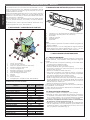 4
4
-
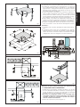 5
5
-
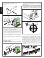 6
6
-
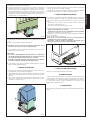 7
7
-
 8
8
-
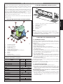 9
9
-
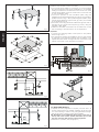 10
10
-
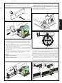 11
11
-
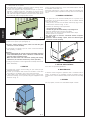 12
12
-
 13
13
-
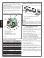 14
14
-
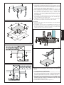 15
15
-
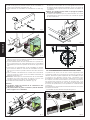 16
16
-
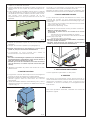 17
17
-
 18
18
-
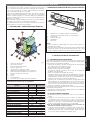 19
19
-
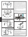 20
20
-
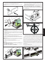 21
21
-
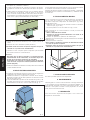 22
22
-
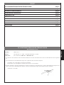 23
23
-
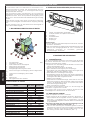 24
24
-
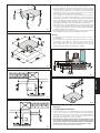 25
25
-
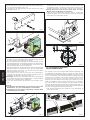 26
26
-
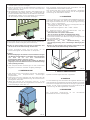 27
27
-
 28
28
-
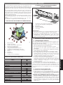 29
29
-
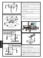 30
30
-
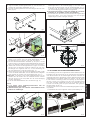 31
31
-
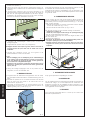 32
32
-
 33
33
-
 34
34
-
 35
35
-
 36
36
-
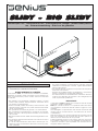 37
37
-
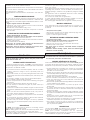 38
38
-
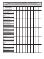 39
39
-
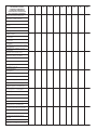 40
40
-
 41
41
-
 42
42
-
 43
43
-
 44
44


Genius SLIDY BIG SLIDY 115 Instrucciones de operación
- Categoría
- Abridor de puerta
- Tipo
- Instrucciones de operación
en otros idiomas
Artículos relacionados
-
Genius SLIDY BIG SLIDY Instrucciones de operación
-
-
-
-
Genius MILORD 3624 C Instrucciones de operación
-
-
-
-
-