
INSTALLATION
AXOR Select
18310181
AXOR Select
18311181
EN ⁄ Assembly instructions
FR ⁄ Instructions de montage
ES ⁄ Instrucciones de montaje

2
ENGLISH ESPAÑ OLFRANÇAIS
DONNÉES TECHNIQUES
Pression d’eau
recommandée 15 - 75 PSI (0.1 - 0.5 MPa)
maximum 145 PSI (1 MPa)
Température d'eau chaude
recommandée 120°-140° F (48° - 60° C)*
maximum 158°F (70° C)*
Capacité nominale 1.75 GPM (6.6 L/min)
* Vous devez connaître et respecter tous les codes de
plomberie locaux applicables pour le réglage de la
température du chauffe-eau.
À PRENDRE EN CONSIDÉRATION POUR
L’INSTALLATION
/ Pour de meilleurs résultats, Hansgrohe recommande
que ce produit soit installé par un plombier
professionnel licencié.
/ Avant son montage, s'assurer que le produit n'a
subi aucun dommage pendant le transport Après le
montage, tout dommage de transport ou de surface
ne pourra pas être reconnu.
/ Veuillez lire attentivement ces instructions avant de
procéder à l’installation. Assurez-vous de disposer
de tous les outils et du matériel nécessaires pour
l’installation.
/ La cartouche thermostatique et les cartouches
d’arrêt sont fournies avec le jeu de garniture.
/ Robinetterie brute 18310181 uniquement : cette
valve est destinée à une fonction de douche plus une
douchette. À utiliser avec la garniture 18355XXX
(non fournie).
/ Robinetterie brute 18311181 uniquement : cette
valve est destinée à deux fonctions de douche plus
une douchette. À utiliser avec la garniture 18356XXX
(non fournie).
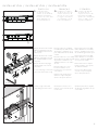
Le mitigeur thermostatique doit être installé avec
les ports d’alimentation d’eau chaude et froide
de ¾ po orientés vers le bas (illustration A).
N’installez pas le mitigeur avec les ports
orientés vers le haut ou le côté (illustration B).
/ La pièce intérieure n’inclut pas de robinets d’arrêt.
Si vous voulez des robinets d’arrêt, installez-les sur
les conduites d’alimentation d’eau chaude et d’eau
froide dans un endroit facilement accessible à
l'extérieur de la douche. Les robinets d’arrêt ne sont
pas disponibles auprès de Hansgrohe.
/ Ce produit devrait être seulement utilisé avec
les pommes de douche évaluées à 1.3 GPM
(5.0 L/min) ou plus.
/ Pour empêcher des blessures par ébouillantement,
la température de sortie maximale du robinet de
douche ne doit pas excéder 120°F (49° C). Au
Massachusetts, la température de sortie maximale
du robinet de douche ne doit pas excéder 112°F
(44° C).
/ Conservez ce livret et le reçu (ou une autre preuve
sur laquelle figurent la date et l’endroit de l’achat)
pour ce produit dans un endroit sûr. Le reçu est
requis si vous commandez des pièces sous garantie.
DATOS TECNICOS
Presión en servicio
recomendada 15 - 75 PSI (0.1 - 0.5 MPa)
max. 145 PSI (1 MPa)
Temperatura del agua caliente
recomendada 120°-140° F (48° - 60° C)*
max. 158°F (70° C)*
Caudal máximo 1.75 GPM (6.6 L/min)
* Debe conocer y cumplir todos los códigos locales aplica-
bles para ajustar la temperatura del calentador de agua.
CONSIDERACIONES PARA LA
INSTALACIÓN
/ Para obtener mejores resultados, la instalación
debe estar a cargo de un plomero profesional
matriculado.
/ Antes del montaje se debe examinarse el
producto contra daños de transporte. Después
de la instalación no se reconoce ningún daño de
transporte o de superficie.
/ Antes de comenzar la instalación, lea estas
instrucciones detenidamente. Asegúrese de tener
las herramientas y los insumos necesarios para
completar la instalación.
/ El cartucho termostático y los cartuchos de cierre se
incluyen en el kit de pieza exterior.
/ Únicamente pieza interior de válvula 18310181:
esta válvula es para función de una ducha más una
ducha de mano. Debe instalarse con una pieza
exterior 18355XXX (no incluida).
/ Únicamente pieza interior de válvula 18311181:
esta válvula es para función de dos duchas más
una ducha de mano. Debe instalarse con una
pieza exterior 18356XXX (no incluida).
El mezclador termostático debe instalarse con
los puertos de entrada de agua caliente y fría
de ¾" mirando hacia abajo (ilustración A).
No instale el mezclador con las entradas
mirando hacia arriba o al costado
(ilustración B).
/ La pieza interior no incluye topes. Si desea topes,
instálelos en los suministros de agua caliente y
fría en una ubicación de fácil acceso fuera de la
ducha. Hansgrohe no le proporciona los topes.
/ Este producto debe ser utilizado sólo con
alcachofas de la ducha valoradas en 1.3 GPM
(5.0 L/min) o más.
/ Para evitar escaldaduras, la máxima temperatura de
salida de la válvula de la ducha no debe exceder
los 120°F (49° C). En Massachusetts, la máxima
temperatura de salida de la válvula de la ducha no
debe exceder los 112°F (44° C).
/ Mantenga este folleto y el recibo (u otro
comprobante del lugar y fecha de compra) de este
producto en lugar seguro. El recibo se requiere
en caso de ser necesario solicitar piezas bajo
garantía.
TECHNICAL INFORMATION
Water pressure
Recommended 15 - 75 PSI (0.1 - 0.5 MPa)
Maximum 145 PSI (1 MPa)
Hot water temp.
Recommended 120°-140° F (48° - 60° C)*
Maximum 158°F (70° C)*
Max. flow rate (with trim kit installed) 1.75 GPM
* Please know and follow all applicable local plumbing
codes when setting the temperature on the water heater.
INSTALLATION CONSIDERATIONS
/ Please read over these instructions thoroughly
before beginning installation. Make sure that you
have all tools and supplies needed to complete the
installation.
/ Inspect this product thoroughly before installation.
Claims for shipping damage made after installation
will not be honored.
/ For best results, Hansgrohe recommends that this
unit be installed by a licensed, professional plumber.
/ The thermostatic cartridge and shutoff cartridges
are included with the trim kit.
/ Rough 18310181 only: this valve is for one shower
function plus a handshower.
/ Rough 18311181 only: this valve is for two shower
functions plus a handshower.
The thermostatic mixer must be installed
with the ¾" hot and cold inlet ports
facing downwards (illustration A).
Do not install the mixer with the inlets
facing upwards or to the side (illustration B).
/ The rough does not include stops. If stops are
desired, install them on the hot and cold supplies
in an easily accessible location outside the shower.
Stops are not available from Hansgrohe.
/ The thermostatic mixer is for use with shower heads
rated at 1.3 GPM (5.0 L/min) or higher.
/ To prevent scald injury, the maximum output
temperature of the shower mixing valve (not
included) must be no higher than 120°F (49°C).
In Massachusetts, the maximum output temperature
can be no higher than 112°F (44°C).
/ Keep this booklet and the receipt (or other proof
of date and place of purchase) for this product in
a safe place. The receipt is required should it be
necessary to request warranty parts.

3
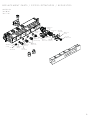
AXOR Select
18310181
AXOR Select
18311181
¾" hot
chaud
caliente
¾" cold
froid
frío
½" shower
douche
ducha
½" shower
douche
ducha
¾" hot
chaud
caliente
¾" cold
froid
frío
½" shower
douche
ducha
19¹³⁄₁₆" (504 mm)
19¼" (489 mm)
2½"
(65 mm)
G½
G¾
G¾
G½
2¾"
(71 mm)
1¾"
(45 mm)
7⅝"(195 mm) 7"(178 mm)
3¼" (82 mm)
3¼" (82 mm)
5¼"(132 mm)
2⅜"(60 mm)
1⅝"
(40 mm)
2½"
(65 mm)
G½
½ NPT
G¾
¾ NPT
18⅜" (467 mm)
4¾"(122 mm)
3⅜"
(87 mm)
1⅜"
(35mm)
⅜" (10 mm)
16⅞" (428 mm)
1⅜"
(35mm)
9⅞" (250 mm)7" (178 mm)
9" (228 mm) 9" (228mm)
21⅛" (538 mm)
4¾"(122 mm)
3⅜"
(87 mm)
1⅜"
(35mm)
⅜" (10 mm)
2¾"
(71 mm)
10¼" (259 mm)
19⅝" (498 mm)
7" (178 mm)
10⅜" (263 mm) 10⅜" (263 mm)
22⅝" (575 mm)
22¹⁄₁₆" (560 mm)
G½ G½
2½"
(65 mm)
G¾
G¾
7⅝"(195 mm)
2¾"
(71 mm)
2¾"
(71 mm)
7"(178 mm)
G½
G½
1¾"
(45 mm)
3¼" (82 mm)
3¼" (82 mm)
5¼"(132 mm)
2⅜"(60 mm)
G¾
¾ NPT
1⅝"
(40 mm)
2½"
(65 mm)
G½
½ NPT
A B

4
½"
½"
¾"
¾"
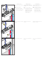
47¼" (1200 mm)
84⅝" (2150 mm)
94½" (2400 mm)
INSTALLATION SUGGESTIONS / SUGGESTIONS D'INSTALLATION /
SUGERENCIAS PARA LA INSTALACIÓN
47¼" (1200 mm)
86⅝" (2200 mm)
94½" (2400 mm)
15¾"
(400 mm)
15¾"
(400 mm)
23⅝"
(600 mm)
½"
¾"
¾"
35278XXX
1⅜"
(35 mm)
35275XXX
AXOR Select
18310181
AXOR Select
18311181

ENGLISH ESPAÑ OLFRANÇAIS
5
max.
max.
min.
max.
min.
min. 3⅜"
(87 mm)
max.
min.
max.
min.
max. 4¾"
(122 mm)
INSTALLATION / INSTALLATION / INSTALACIÓN
Install this valve
so that the outside
surface of the finished
wall falls somewhere
between the "min" and
"max" markings on
the installation box.
Screw the rough to the header
board, making sure that it is level.
Wrap the threads on the ¾" NPT
adapters using plumber's thread
tape. Install them on the hot and
cold inlet ports.
Wrap the threads on the ½" NPT
adapter(s) using plumber's thread
tape. Install the adapter(s) on the
outlet port(s).
Wrap the threads on the plug(s).
Install the plug(s) on the unused
outlet port(s).
Use one of the plugs to connect the
support to the bottom of the rough.
Installez ces vannes
de façon à ce que la
surface extérieure du
mur fini se trouve entre
les lignes « minimum »
et « maximum » de la
boîte d’installation.
Enroulez les filets sur les adapta-
teurs NPT ¾ po à l’aide de ruban
de plomberie. Installez-les sur les
ports d’alimentation d’eau chaude
et froide.
Enroulez les filets sur le ou les adap-
tateurs NPT ½ po à l’aide de ruban
de plomberie. Installez le ou les
adaptateurs dans le ou les orifices
de sortie.
Enroulez les filets sur le ou les
bouchons. Installez le ou les
bouchons sur le ou les ports de
sortie inutilisés.
Utilisez l’un des bouchons pour
rattacher le support à la partie
inférieure de la pièce intérieure.
Vissez la pièce intérieure sur le
panneau, en vous assurant qu’elle
soit de niveau.
Instale esta válvula
de modo que la
superficie exterior de
la pared terminada
quede entre las marcas
"mín." y "máx.” en la
caja de instalación.
Envuelva las roscas en los adap-
tadores NPT de ¾" con cinta de
plomero. Instálelas en los puertos
de entrada de agua caliente y fría.
Envuelva las roscas en los adap-
tadores NPT de ½” con cinta de
plomero. Instale los adaptadores
en los puertos de salida.
Envuelva las roscas en el tapón.
Instale los tapones en los puertos
de salida no utilizados.
Use uno de los tapones para
conectar el soporte a la parte
inferior de la pieza interior.
Atornille la pieza interior al panel
de cabezal, asegurándose de que
esté nivelado.
12 mm
¾"
¾"
½"
1
2
1
2 3

ENGLISH ESPAÑ OLFRANÇAIS
6
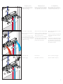
Make sure that the pipes are firmly
secured.
Remove the flush housing insert.
Install the ¾" hot and cold supply
lines.
To insure correct
function of the
thermostatic mixing
valve, the hot must be
on the left and the cold
must be on the right.
Installez les conduites d’alimenta-
tion d’eau chaude et d’eau froide
de ¾ po.
Pour que le mitigeur
thermostatique fonctionne
correctement, la conduite
d’alimentation de l'eau
chaude doit être installée
à gauche et la conduite
d'eau froide doit être
installée à droite.
Assurez-vous de bien fixer les
conduites.
Retirez l’insert du compartiment
affleurant.
Instale las tuberías de suministro de
agua fría y caliente de ¾”.
Para garantizar que
la válvula mezcladora
termostática funcione
correctamente, el
suministro de agua
caliente debe estar a
la izquierda y el de
agua fría a la derecha.
Asegúrese de que las tuberías estén
firmemente sujetadas.
Retire el inserto del alojamiento de
descarga.
hot
chaud
caliente
cold
froid
frío
4
5
¾"
¾"
½"
3
1
2
3
4

ENGLISH ESPAÑ OLFRANÇAIS
7
Remove the plugs from the ther-
mostatic mixer housing and the
handshower housing.
Turn the water on at the main.
Flush the hot and cold supplies for
at least 5 minutes.
The cold supply will flush through
the thermostatic mixer housing and
the hot supply will flush through the
handshower housing.
Turn the water off.
Reinstall the plugs.
Retirez les bouchons du comparti-
ment du mitigeur thermostatique et
du compartiment de la douchette.
Ouvrez l'eau à la valve principale.
Rincez les conduites d’alimentation
d’eau chaude et d’eau froide pen-
dant au moins 5 minutes.
L’eau froide rincera le compartiment
du mitigeur thermostatique tandis
que l’eau chaude rincera le com-
partiment de la douchette.
Fermez l'eau.
Réinstallez les bouchons.
Retire los tapones de a carcasa
del mezclador termostático y de la
carcasa de la ducha de mano.
Abra el paso del agua en la entra-
da del suministro.
Purgue los suministros de agua cali-
ente y agua fría durante al menos
5 minutos.
El suministro de agua fría se purga
a través de la carcasa del mezcla-
dor termostático y el suministro de
agua caliente mediante la carcasa
de la ducha de mano.
Cierre el suministro de agua.
Vuelva a instalar los tapones.
7
8
17 mm
17 mm
17 mm
17 mm
6
1
1
> 5 min
2
2

ENGLISH ESPAÑ OLFRANÇAIS
8
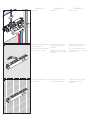
Install the sheetrock or green board
up to the installation box.
Seal the wall around the installation
box using waterproof sealant.
Install the finished wall surface up to
the installation box.
Install the insert. Installez l’insert.
Installez la plaque de plâtre ou
la céramique jusqu’à la boîte
d’installation.
Scellez le mur autour du boîtier
d’installation à l'aide d'un agent
d'étanchéité.
Installez la surface finie du mur
jusqu’à la boîte d’installation.
Instale el inserto.
Instale el estuco o panel verde
hasta la caja de instalación.
Selle la pared alrededor de la
caja de instalación con un sellador
impermeable.
Instale la superficie de la pared
terminada hasta la caja de
instalación.
10
11
9

9
REPLACEMENT PARTS / PIÈCES DÉTACHÉES / REPUESTOS
98163000
(15x2)
(G 1⁄2)
SW 17 mm
(M5x16)
SW 4 mm
SW 24 mm
98198000
(38x2.5)
98383000
(34x2)
(G 1⁄2)
SW 12 mm
98181000
(18x2)
98197000
(20x1.5)
95169000
(21.95x1.78)
98165000
(20x2)
(M28x1.5)
SW 17 mm
(G 3⁄4)
SW 17 mm
(M28x1.5)
SW 17 mm
(G 1⁄2)
SW 17 mm
AXOR Select
18310181
18311181
98128000
(13x2)

10

11
This warranty is limited to products manufactured by Hansgrohe, Inc. (“Hansgrohe”) that are
purchased by a consumer in the United States or Canada after March 1, 1996, and installed
in either the United States or in Canada.
WHO IS COVERED BY THE WARRANTY
This limited warranty extends to the original purchaser only. This warranty is non-transferable.
Hansgrohe neither assumes nor authorizes any person to create for it any other obligation or
liability in connection with this product.
LENGTH OF WARRANTY
If you are a consumer who purchased the product for use primarily for personal, family or
household purposes, this limited warranty starts on the date of purchase and extends for as
long as you own the product and the home in which the product is originally installed. If you
purchased the product for use primarily for any other purpose, including, without limitation, a
commercial purpose, this limited warranty starts on the date of purchase and extends (i) for 1
year, with respect to Hansgrohe and Commercial products, and (ii) for 5 years, with respect
to Axor products. The Rubbed Bronze finish is subject to a 3-year limited warranty starting on
the date of purchase.
WHAT IS COVERED BY THE WARRANTY
This limited warranty covers only your Hansgrohe manufactured product. Hansgrohe warrants
this product against defects in material or workmanship as follows:
Hansgrohe will replace at no charge for parts only or, at its option, replace any product
or part of the product that proves defective because of improper workmanship and/
or material, under normal installation, use, service and maintenance. If Hansgrohe is
unable to provide a replacement and repair is not practical or cannot be made in timely
fashion, Hansgrohe may elect to refund the purchase price in exchange for the return of
the product. REPAIR OR REPLACEMENT (OR, IN LIMITED CIRCUMSTANCES, REFUND
OF THE PURCHASE PRICE) AS PROVIDED UNDER THIS LIMITED WARRANTY IS THE
EXCLUSIVE REMEDY OF THE PURCHASER.
WHAT IS NOT COVERED BY THE WARRANTY
A. Conditions, malfunctions or damage not resulting from defects in material or workmanship.
B. Conditions, malfunctions or damage resulting from (1) normal wear and tear, improper
installation, improper maintenance, misuse, abuse, negligence, accident or alteration;
(2) the use of abrasive or caustic cleaning agents or “no-rinse” cleaning products, or the
use of the product in any manner contrary to the product instructions; or (3) conditions
in the home such as excessive water pressure or corrosion.
C. Labor and other expenses for disconnection, deinstallation, or return of the product for
warranty service (including but not limited to proper packaging and shipping costs), or
for installation or reinstallation of the product.
D. Accessories, connected materials and products, or related products not manufactured
by Hansgrohe.
E. Any Hansgrohe or Axor product sold for display purposes.
HANSGROHE SHALL NOT BE LIABLE TO PURCHASER OR ANY OTHER PERSON FOR ANY
INCIDENTAL, SPECIAL OR CONSEQUENTIAL DAMAGES, ARISING OUT OF BREACH OF
THIS LIMITED WARRANTY.
Some provinces and some states do not allow the exclusion or limitation of incidental or
consequential damages, so the above limitation or exclusion may not apply to you.
TO OBTAIN WARRANTY PARTS OR INFORMATION
Contact your Hansgrohe retailer, or contact Technical Service at:
Hansgrohe, Inc.
1492 Bluegrass Lakes Parkway
Alpharetta, GA 30004
Toll-free 800-334-0455
In requesting warranty service, you will need to provide:
1. The sales receipt or other evidence of the date and place of purchase.
2. A description of the problem.
3. Delivery of the product or the defective part, postage prepaid and carefully packed
and insured, to:
Hansgrohe, Inc.
1492 Bluegrass Lakes Parkway
Alpharetta, GA 30004
Toll-free 800-334-0455
When warranty service is completed, any repaired or replacement product or part will be
returned to you postage prepaid. REVISED MAY 1, 2016.
PRODUCT INSTRUCTIONS AND QUESTIONS
Upon purchase or prior to installation, please carefully inspect your Hansgrohe product for any
damage or visible defect. Prior to installing, always carefully study the enclosed instructions on
the proper installation and the care and maintenance of this product. If you have questions at
any time about the use, installation or performance of your Hansgrohe product, or this warranty,
please write us or call us toll-free at 800-334-0455.
LIMITED CONSUMER WARRANTY

AXOR ⁄ Hansgrohe, Inc.
1490 Bluegrass Lakes Parkway
Alpharetta, GA 30004
Tel. 800-334-0455
Fax 770-889-1783
axor-design.com
US - Installation Instructions • Part No. 91498621 • Revised 09/2018
Transcripción de documentos
E N ⁄ Assembly instructions FR ⁄ Instructions de montage E S ⁄ Instrucciones de montaje A XOR Select 18311181 A XOR Select 18310181 INSTALL ATION ENGLISH FRANÇAIS ESPAÑOL TEC HN IC AL IN F ORM AT IO N D O N N É E S TEC H NIQUE S DATOS TECNICOS Water pressure Recommended 15 - 75 PSI (0.1 - 0.5 MPa) Maximum 145 PSI (1 MPa) Hot water temp. Recommended 120°-140° F (48° - 60° C)* Maximum 158°F (70° C)* Max. flow rate (with trim kit installed) 1.75 GPM Pression d’eau recommandée 15 - 75 PSI (0.1 - 0.5 MPa) maximum 145 PSI (1 MPa) Température d'eau chaude recommandée 120°-140° F (48° - 60° C)* maximum 158°F (70° C)* Capacité nominale 1.75 GPM (6.6 L/min) Presión en servicio recomendada 15 - 75 PSI (0.1 - 0.5 MPa) max. 145 PSI (1 MPa) Temperatura del agua caliente recomendada 120°-140° F (48° - 60° C)* max. 158°F (70° C)* Caudal máximo 1.75 GPM (6.6 L/min) * Please know and follow all applicable local plumbing codes when setting the temperature on the water heater. * Vous devez connaître et respecter tous les codes de plomberie locaux applicables pour le réglage de la température du chauffe-eau. * Debe conocer y cumplir todos los códigos locales aplicables para ajustar la temperatura del calentador de agua. INSTALL ATI ON CO N SID E R ATI O N S // Please read over these instructions thoroughly before beginning installation. Make sure that you have all tools and supplies needed to complete the installation. // Inspect this product thoroughly before installation. Claims for shipping damage made after installation will not be honored. // For best results, Hansgrohe recommends that this unit be installed by a licensed, professional plumber. // The thermostatic cartridge and shutoff cartridges are included with the trim kit. // Rough 18310181 only: this valve is for one shower function plus a handshower. // Rough 18311181 only: this valve is for two shower functions plus a handshower. The t her m os t at ic m ixe r m u s t b e i n s ta l l e d wit h t he ¾ " h ot an d c o l d i n l et p o r ts facing d ow nwa rd s (illustration A). D o not in s t all t h e m ixe r w i t h t h e i n l ets fa cing upwards or t o t h e s i d e (illustration B) . // The rough does not include stops. If stops are desired, install them on the hot and cold supplies in an easily accessible location outside the shower. Stops are not available from Hansgrohe. À P R E N D R E E N CONSIDÉ R ATION POUR L’ I N STA L L ATION // Pour de meilleurs résultats, Hansgrohe recommande que ce produit soit installé par un plombier professionnel licencié. // Avant son montage, s'assurer que le produit n'a subi aucun dommage pendant le transport Après le montage, tout dommage de transport ou de surface ne pourra pas être reconnu. // Veuillez lire attentivement ces instructions avant de procéder à l’installation. Assurez-vous de disposer de tous les outils et du matériel nécessaires pour l’installation. // La cartouche thermostatique et les cartouches d’arrêt sont fournies avec le jeu de garniture. // Robinetterie brute 18310181 uniquement : cette valve est destinée à une fonction de douche plus une douchette. À utiliser avec la garniture 18355XXX (non fournie). // Robinetterie brute 18311181 uniquement : cette valve est destinée à deux fonctions de douche plus une douchette. À utiliser avec la garniture 18356XXX (non fournie). Le mitigeur thermostatique doit être installé avec les ports d’alimentation d’eau chaude et froide de ¾ po orientés vers le bas (illustration A). // The thermostatic mixer is for use with shower heads rated at 1.3 GPM (5.0 L/min) or higher. N’installez pas le mitigeur avec les ports orientés vers le haut ou le côté (illustration B). // To prevent scald injury, the maximum output temperature of the shower mixing valve (not included) must be no higher than 120°F (49°C). In Massachusetts, the maximum output temperature can be no higher than 112°F (44°C). // La pièce intérieure n’inclut pas de robinets d’arrêt. Si vous voulez des robinets d’arrêt, installez-les sur les conduites d’alimentation d’eau chaude et d’eau froide dans un endroit facilement accessible à l'extérieur de la douche. Les robinets d’arrêt ne sont pas disponibles auprès de Hansgrohe. // Keep this booklet and the receipt (or other proof of date and place of purchase) for this product in a safe place. The receipt is required should it be necessary to request warranty parts. // Ce produit devrait être seulement utilisé avec les pommes de douche évaluées à 1.3 GPM (5.0 L/min) ou plus. // Pour empêcher des blessures par ébouillantement, la température de sortie maximale du robinet de douche ne doit pas excéder 120°F (49° C). Au Massachusetts, la température de sortie maximale du robinet de douche ne doit pas excéder 112°F (44° C). // Conservez ce livret et le reçu (ou une autre preuve sur laquelle figurent la date et l’endroit de l’achat) pour ce produit dans un endroit sûr. Le reçu est requis si vous commandez des pièces sous garantie. 2 CONSIDE R ACIONE S PA R A L A INSTA L ACIÓN // Para obtener mejores resultados, la instalación debe estar a cargo de un plomero profesional matriculado. // Antes del montaje se debe examinarse el producto contra daños de transporte. Después de la instalación no se reconoce ningún daño de transporte o de superficie. // Antes de comenzar la instalación, lea estas instrucciones detenidamente. Asegúrese de tener las herramientas y los insumos necesarios para completar la instalación. // El cartucho termostático y los cartuchos de cierre se incluyen en el kit de pieza exterior. // Únicamente pieza interior de válvula 18310181: esta válvula es para función de una ducha más una ducha de mano. Debe instalarse con una pieza exterior 18355XXX (no incluida). // Únicamente pieza interior de válvula 18311181: esta válvula es para función de dos duchas más una ducha de mano. Debe instalarse con una pieza exterior 18356XXX (no incluida). El mezclador termostático debe instalarse con los puertos de entrada de agua caliente y fría de ¾" mirando hacia abajo (ilustración A). No instale el mezclador con las entradas mirando hacia arriba o al costado (ilustración B). // La pieza interior no incluye topes. Si desea topes, instálelos en los suministros de agua caliente y fría en una ubicación de fácil acceso fuera de la ducha. Hansgrohe no le proporciona los topes. // Este producto debe ser utilizado sólo con alcachofas de la ducha valoradas en 1.3 GPM (5.0 L/min) o más. // Para evitar escaldaduras, la máxima temperatura de salida de la válvula de la ducha no debe exceder los 120°F (49° C). En Massachusetts, la máxima temperatura de salida de la válvula de la ducha no debe exceder los 112°F (44° C). // Mantenga este folleto y el recibo (u otro comprobante del lugar y fecha de compra) de este producto en lugar seguro. El recibo se requiere en caso de ser necesario solicitar piezas bajo garantía. A XOR Select 18311181 19¹³⁄₁₆" (504 mm) 22⅝" (575 mm) 19¼" (489 mm) 22¹⁄₁₆" (560 mm) G½ G½ 7⅝"(195 mm) G¾ 2½" (65 mm) G½ G½ G¾ G¾ 7"(178 mm) 2¾" (71 mm) 5¼"(132 mm) 1¾" 2¾" (71 mm) (45 mm) 2⅜"(60 mm) 2½" (65 mm) 5¼"(132 mm) 2⅜"(60 mm) G¾ 2¾" 1¾" (71 mm) (45 mm) 1⅝" (40 mm) 2½" (65 mm) 1⅝" (40 mm) 7"(178 mm) 3¼" (82 mm) 3¼" (82 mm) 2½" (65 mm) G¾ G½ 7⅝"(195 mm) G½ 3¼" (82 mm) G½ G½ 3¼" (82 mm) A XOR Select 18310181 G¾ ¾ NPT ¾ NPT ½ NPT ½ NPT 9⅞" (250 mm) 16⅞" (428 mm) 9" (228 mm) 3⅜" (87 mm) 1⅜" (35mm) ⅜" (10 mm) 1⅜" (35mm) 4¾"(122 mm) 3⅜" (87 mm) 1⅜" (35mm) ⅜" (10 mm) 7" (178 mm) 2¾" (71 mm) ½" shower douche ducha ¾" hot chaud caliente ¾" cold froid frío 10¼" (259 mm) 19⅝" (498 mm) 10⅜" (263 mm) 9" (228mm) ½" shower douche ducha A 7" (178 mm) 4¾"(122 mm) 21⅛" (538 mm) 18⅜" (467 mm) 10⅜" (263 mm) ½" shower douche ducha ¾" hot chaud caliente ¾" cold froid frío B 3 I N STA L L AT I O N S U G G E ST I O N S / S U G G E ST I O N S D ' I N STA L L AT I O N / S U G E R E N C I A S PA R A L A I N STA L AC I Ó N A XOR Select 18310181 3 5 278 X X X ½" 84⅝" (2150 mm) 94½" (2400 mm) ) 47¼" (1200 mm) 1 ( 3 5⅜ " mm ¾" ¾" A XOR Select 18311181 35 275 X X X 86⅝" (2200 mm) 94½" (2400 mm) ½" 23⅝" (600 mm) 4 47¼" (1200 mm) 15¾" (400 mm) 15¾" (400 mm) ½" ¾" ¾" I N STA L L AT I O N / I N STA L L AT I O N / I N STA L AC I Ó N ENGLISH max. min. min. max. max. min. min. 3⅜" (87 mm) max. FRANÇAIS ESPAÑOL I n s ta l l t h i s va l ve s o t h a t t h e ou t s i d e s u r fa c e of t h e f i n i s h ed wa l l fa l l s s om ewh ere b etwe e n t h e "m i n " a n d "m a x " ma r ki n gs on t h e i n s tal l a t i on b ox . In s t a l l ez c es va n n es d e fa ç on à c e q u e l a s u r fa c e ex t ér i eu re d u m u r f i n i s e t rou ve en t re l es l i gn es « m i n i m u m » et « m a x i m u m » d e l a b oî t e d ’i n s t a l l a t i on . In s t a l e es ta vál vula d e m od o q ue la s u p er f i c i e exter ior de l a p a red ter minada q u ed e entre las marcas "m í n ." y "máx.” en la c a j a d e ins talación. Wrap the threads on the ¾" NPT adapters using plumber's thread tape. Install them on the hot and cold inlet ports. Enroulez les filets sur les adaptateurs NPT ¾ po à l’aide de ruban de plomberie. Installez-les sur les ports d’alimentation d’eau chaude et froide. Envuelva las roscas en los adaptadores NPT de ¾" con cinta de plomero. Instálelas en los puertos de entrada de agua caliente y fría. min. max. max. 4¾" (122 mm) 1 ½" Wrap the threads on the ½" NPT adapter(s) using plumber's thread tape. Install the adapter(s) on the outlet port(s). Wrap the threads on the plug(s). Install the plug(s) on the unused outlet port(s). ¾" ¾" Enroulez les filets sur le ou les adaptateurs NPT ½ po à l’aide de ruban de plomberie. Installez le ou les adaptateurs dans le ou les orifices de sortie. Enroulez les filets sur le ou les bouchons. Installez le ou les Use one of the plugs to connect the bouchons sur le ou les ports de support to the bottom of the rough. sortie inutilisés. Utilisez l’un des bouchons pour rattacher le support à la partie inférieure de la pièce intérieure. Envuelva las roscas en los adaptadores NPT de ½” con cinta de plomero. Instale los adaptadores en los puertos de salida. Envuelva las roscas en el tapón. Instale los tapones en los puertos de salida no utilizados. Use uno de los tapones para conectar el soporte a la parte inferior de la pieza interior. 12 mm 2 Screw the rough to the header board, making sure that it is level. Vissez la pièce intérieure sur le panneau, en vous assurant qu’elle soit de niveau. Atornille la pieza interior al panel de cabezal, asegurándose de que esté nivelado. 1 2 3 5 ENGLISH 3 Install the ¾" hot and cold supply lines. ½" To i n s u re c or rec t f u n c ti o n of t h e thermostatic mixing va l ve , t h e h ot m u s t b e o n t h e l ef t a n d t h e c ol d m u s t b e on t h e r i gh t . 4 3 1 FRANÇAIS Installez les conduites d’alimentation d’eau chaude et d’eau froide de ¾ po. Pour que le mitigeur thermostatique fonctionne correctement, la conduite d’alimentation de l'eau chaude doit être installée à gauche et la conduite d'eau froide doit être installée à droite. ESPAÑOL Instale las tuberías de suministro de agua fría y caliente de ¾”. Pa ra g a rantizar q ue l a vá l v u l a mezcladora t er m os t á tica funcione c or rec t a mente, el s u m i n i s t ro de ag ua c a l i en t e debe es tar a l a i zq u i erda y el de a gu a f r í a a la derecha. 2 ¾" ¾" 4 hot chaud caliente 5 6 Make sure that the pipes are firmly secured. Assurez-vous de bien fixer les conduites. Asegúrese de que las tuberías estén firmemente sujetadas. Remove the flush housing insert. Retirez l’insert du compartiment affleurant. Retire el inserto del alojamiento de descarga. cold froid frío ENGLISH 6 FRANÇAIS ESPAÑOL Remove the plugs from the thermostatic mixer housing and the handshower housing. Retirez les bouchons du compartiment du mitigeur thermostatique et du compartiment de la douchette. Retire los tapones de a carcasa del mezclador termostático y de la carcasa de la ducha de mano. Turn the water on at the main. Ouvrez l'eau à la valve principale. Abra el paso del agua en la entrada del suministro. Flush the hot and cold supplies for at least 5 minutes. The cold supply will flush through the thermostatic mixer housing and the hot supply will flush through the handshower housing. Rincez les conduites d’alimentation d’eau chaude et d’eau froide pen- Purgue los suministros de agua caliente y agua fría durante al menos dant au moins 5 minutes. 5 minutos. L’eau froide rincera le compartiment El suministro de agua fría se purga du mitigeur thermostatique tandis a través de la carcasa del mezclaque l’eau chaude rincera le comdor termostático y el suministro de partiment de la douchette. agua caliente mediante la carcasa de la ducha de mano. Turn the water off. Fermez l'eau. Cierre el suministro de agua. Reinstall the plugs. Réinstallez les bouchons. Vuelva a instalar los tapones. 17 m m 17 m m 7 1 2 > 5 min 8 1 17 m m 2 17 m m 7 ENGLISH 9 10 11 8 Install the insert. FRANÇAIS Installez l’insert. ESPAÑOL Instale el inserto. Install the sheetrock or green board Installez la plaque de plâtre ou la céramique jusqu’à la boîte up to the installation box. d’installation. Seal the wall around the installation Scellez le mur autour du boîtier box using waterproof sealant. d’installation à l'aide d'un agent d'étanchéité. Instale el estuco o panel verde hasta la caja de instalación. Install the finished wall surface up to Installez la surface finie du mur jusqu’à la boîte d’installation. the installation box. Instale la superficie de la pared terminada hasta la caja de instalación. Selle la pared alrededor de la caja de instalación con un sellador impermeable. R E P L AC E M E N T PA RTS / P I È C E S D É TAC H É E S / R E P U E STO S A XOR Select 18310181 18311181 98165000 (20x2) 95169000 (21.95x1.78) 98128000 (13x2) (G 1⁄2) SW 12 mm 98197000 (20x1.5) 98383000 (34x2) SW 24 mm (M28x1.5) SW 17 mm (G 3⁄4) 98198000 SW 17 mm (38x2.5) (M5x16) SW 4 mm 98163000 (15x2) (G 1⁄2) SW 17 mm (M28x1.5) SW 17 mm 98181000 (18x2) (G 1⁄2) SW 17 mm 9 10 LIMITED CONSUMER WARRANT Y This warranty is limited to products manufactured by Hansgrohe, Inc. (“Hansgrohe”) that are purchased by a consumer in the United States or Canada after March 1, 1996, and installed in either the United States or in Canada. D. Accessories, connected materials and products, or related products not manufactured by Hansgrohe. E. Any Hansgrohe or Axor product sold for display purposes. WHO IS COVERED BY THE WARRANTY HANSGROHE SHALL NOT BE LIABLE TO PURCHASER OR ANY OTHER PERSON FOR ANY INCIDENTAL, SPECIAL OR CONSEQUENTIAL DAMAGES, ARISING OUT OF BREACH OF THIS LIMITED WARRANTY. This limited warranty extends to the original purchaser only. This warranty is non-transferable. Hansgrohe neither assumes nor authorizes any person to create for it any other obligation or liability in connection with this product. LENGTH OF WARRANTY If you are a consumer who purchased the product for use primarily for personal, family or household purposes, this limited warranty starts on the date of purchase and extends for as long as you own the product and the home in which the product is originally installed. If you purchased the product for use primarily for any other purpose, including, without limitation, a commercial purpose, this limited warranty starts on the date of purchase and extends (i) for 1 year, with respect to Hansgrohe and Commercial products, and (ii) for 5 years, with respect to Axor products. The Rubbed Bronze finish is subject to a 3-year limited warranty starting on the date of purchase. WHAT IS COVERED BY THE WARRANTY This limited warranty covers only your Hansgrohe manufactured product. Hansgrohe warrants this product against defects in material or workmanship as follows: Hansgrohe will replace at no charge for parts only or, at its option, replace any product or part of the product that proves defective because of improper workmanship and/ or material, under normal installation, use, service and maintenance. If Hansgrohe is unable to provide a replacement and repair is not practical or cannot be made in timely fashion, Hansgrohe may elect to refund the purchase price in exchange for the return of the product. REPAIR OR REPLACEMENT (OR, IN LIMITED CIRCUMSTANCES, REFUND OF THE PURCHASE PRICE) AS PROVIDED UNDER THIS LIMITED WARRANTY IS THE EXCLUSIVE REMEDY OF THE PURCHASER. Some provinces and some states do not allow the exclusion or limitation of incidental or consequential damages, so the above limitation or exclusion may not apply to you. TO OBTAIN WARRANTY PARTS OR INFORMATION Contact your Hansgrohe retailer, or contact Technical Service at: Hansgrohe, Inc. 1492 Bluegrass Lakes Parkway Alpharetta, GA 30004 Toll-free 800-334-0455 In requesting warranty service, you will need to provide: 1. 2. 3. The sales receipt or other evidence of the date and place of purchase. A description of the problem. Delivery of the product or the defective part, postage prepaid and carefully packed and insured, to: Hansgrohe, Inc. 1492 Bluegrass Lakes Parkway Alpharetta, GA 30004 Toll-free 800-334-0455 When warranty service is completed, any repaired or replacement product or part will be returned to you postage prepaid. REVISED MAY 1, 2016. WHAT IS NOT COVERED BY THE WARRANTY PRODUCT INSTRUCTIONS AND QUESTIONS A. Conditions, malfunctions or damage not resulting from defects in material or workmanship. B. Conditions, malfunctions or damage resulting from (1) normal wear and tear, improper installation, improper maintenance, misuse, abuse, negligence, accident or alteration; (2) the use of abrasive or caustic cleaning agents or “no-rinse” cleaning products, or the use of the product in any manner contrary to the product instructions; or (3) conditions in the home such as excessive water pressure or corrosion. C. Labor and other expenses for disconnection, deinstallation, or return of the product for warranty service (including but not limited to proper packaging and shipping costs), or for installation or reinstallation of the product. Upon purchase or prior to installation, please carefully inspect your Hansgrohe product for any damage or visible defect. Prior to installing, always carefully study the enclosed instructions on the proper installation and the care and maintenance of this product. If you have questions at any time about the use, installation or performance of your Hansgrohe product, or this warranty, please write us or call us toll-free at 800-334-0455. 11 1490 Bluegrass Lakes Parkway Alpharetta, GA 30004 Tel. 800-334-0455 Fax 770-889-1783 axor-design.com U S - I n s t al l a t i o n I ns t r u c t i o n s • Pa r t N o . 914 98 621 • Revi se d 0 9/ 2018 A XO R ⁄ Hansgrohe, Inc.-
 1
1
-
 2
2
-
 3
3
-
 4
4
-
 5
5
-
 6
6
-
 7
7
-
 8
8
-
 9
9
-
 10
10
-
 11
11
-
 12
12


en otros idiomas
- français: Hans Grohe 18310181 Guide d'installation
- English: Hans Grohe 18310181 Installation guide
Otros documentos
-
Axor Terrano 41189 Series Assembly Instructions
-
Axor 18355001 Thermostatic Module Trim Select for 2 Functions Assembly Instruction
-
-
-
-
-
Hansgrohe 27115821 Guía de instalación
-
-
-
Axor 16801001 Thermostatic Trim with Volume Control Assembly Instruction