
40270-308-05
Rev. 01, 02/2014
Replaces 40270-308-04 03/2006
Instruction Bulletin
Circuit Breaker Installation for Homeline
TM
Combination Service Entrance Devices
Retain for future use.
™
Introduction
Homeline
TM
Combination Service Entrance Devices are designed to
restrict the installation of more overcurrent devices than that number
for which it was designed. Be advised that the plug-on connection
arrangement for HOMT circuit breakers is different from HOM circuit
breakers.
DANGER
HAZARD OF ELECTRIC SHOCK, EXPLOSION OR ARC FLASH
• Apply appropriate personal protective equipment (PPE) and follow safe electrical
work practices. See NFPA 70E or CSA Z462.
• This equipment must only be installed and serviced by qualified electrical
personnel.
• Turn off all power supplying this equipment before working on or inside equipment.
• Always use a properly rated voltage sensing device to confirm power is off.
• Replace all devices, doors and covers before turning on power to this equipment.
Failure to follow these instructions will result in death or serious injury.
ENGLISH

© 2014 Schneider Electric USA All Rights Reserved
Circuit Breaker Installation for Homeline
®
Combination Service Entrance Devices 40270-308-05
Instruction Bulletin Rev. 01, 02/2014
2
ENGLISH
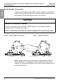
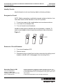
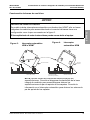
Double Row Bus Construction
Tandem circuit breaker type HOMT may be installed in combination
service entrance devices where the bus bar connector has a slot at
the centerline of the desired pole space. See Figure 1.
Note: Tighten all electrical connections to specifications. See lug
torque data chart on combination service entrance device wiring
diagram for torque specifications. See circuit breaker marking for lug
torque specifications.
NOTICE
HAZARD OF EQUIPMENT DAMAGE
Do not use excessive force to install a HOMT tandem circuit breaker where no
connector slot is provided. See Figure 1.
Failure to follow this instruction will result in damage to the circuit breaker case.
Plug-On Jaws
Wire Terminal
Mounting Hook
Bus Bar Connection
Connection Slot
Bus Bar Connection
(Rejects HOMT)
No Connection Slot for HOMT
Mounting Hook
Wire Terminal
Figure 1: HOM or HOMT Circuit Breaker
Figure 2: HOM Circuit Breaker

© 2014 Schneider Electric USA All Rights Reserved
40270-308-05 Circuit Breaker Installation for Homeline
®
Combination Service Entrance Devices
Rev. 01, 02/2014 Instruction Bulletin
3
ENGLISH
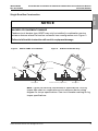
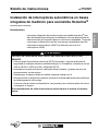
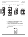
Single Row Bus Construction
Note: Tighten all electrical connections to specifications. See lug
torque data chart on combination service entrance devise wiring
diagram for torque specifications. See circuit breaker marking for lug
torque specifications.
NOTICE
HAZARD OF EQUIPMENT DAMAGE
Tandem circuit breaker type HOMT may only be installed in combination service
entrance devices where the bus bar connector has a configuration as in Figure 3.
Failure to follow this instruction will result in equipment damage.
Plug-On Jaws
Mounting Hook
Bus Bar
Connection
Mounting Hook
Bus Bar Connection (Rejects HOMT)
Wire Terminal
Wire Terminal
Figure 3: HOM or HOMT Circuit Breaker Figure 4: HOM Circuit Breaker Only

© 2014 Schneider Electric USA All Rights Reserved
Circuit Breaker Installation for Homeline
®
Combination Service Entrance Devices 40270-308-05
Instruction Bulletin Rev. 01, 02/2014
4
ENGLISH
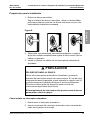
Remove Cover Twistouts
• Remove only those twistouts which match installed circuit
breakers by twisting out with pliers at the center of twistout.
• Close unused circuit breaker openings with filler plates.
• Order catalog number HOMFP for filler plates. Each filler plate
closes one pole branch circuit breaker opening.
Figure 7:
.99
25
.38
10
.37
9
.74
19
.87
22
1.98
50
1.73
44
1.49
38
1.24
31
1.73
44
.99
25
1.86
47
.98
25
.51
13
1.97
50
.38
10
1.55
39
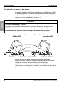
HOM 1-POLE HOM 2-POLE
HOMT 2-POLE
HOMT 4-POLE
Figure 5: HOM Circuit Breaker Figure 6: HOMT Circuit Breaker

© 2014 Schneider Electric USA All Rights Reserved
40270-308-05 Circuit Breaker Installation for Homeline
®
Combination Service Entrance Devices
Rev. 01, 02/2014 Instruction Bulletin
5
ENGLISH
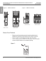
Prepare for Installation
1. Remove knockouts.
Appropriate to knockout pattern, drive center knockout inward or
outward. Alternately pry up or drive in outer rings one at a time to
opening required.
Figure 8:
2. Select the proper cable clamp, or use other approved methods for
securing the cable conduit to the enclosure.
3. Install and wire branch circuit breakers.
Circuit Breaker Installation
1. Turn off circuit breaker.
2. Insert wire terminal end of circuit breaker into mounting hook.
3. Push circuit breaker inward until plug-on jaws plug securely on to
bus bar connector.
4. Install wires.
NOTICE
CAUTION
HAZARD OF EQUIPMENT DAMAGE
Use only Homeline
TM
circuit breakers and replacement parts with
this product. Use of other components voids the warranty, may void
the UL listing and may result in personal injury or equipment
damage. Refer to device markings for specific restrictions.
Failure to follow this instruction can result in personal injury
or equipment damage.

Schneider Electric USA
1415 S. Roselle Road
Palatine, IL 60067 USA
1-888-SquareD (1-888-778-2733)
www.us.SquareD.com
Circuit Breaker Installation for Homeline
®
Combination Service Entrance Devices 40270-308-05
Instruction Bulletin Rev. 01, 02/2014
Electrical equipment should be installed, operated, serviced, and
maintained only by qualified personnel. No responsibility is assumed
by Schneider Electric for any consequences arising out of the use of
this material.
© 2014 Schneider Electric USA All Rights Reserved
™
Identify Circuits
Identify branch circuits on directory label or directory stickers.
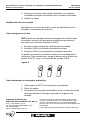
Energize the Circuit
NOTE: Before energizing combination service entrance devices, turn
main and branch circuit breakers to the OFF position.
1. Turned on power to the combination service entrance device.
2. Turn main circuit breaker ON.
3. Turn on branch circuit breakers.
Handle at mid position indicates the circuit breaker is tripped. To
reset, move handle to the off position and then to the on position.
Figure 9:
Removal of Circuit Breakers
1. Turn circuit breakers OFF.
2. Remove wires.
3. Disconnect plug-on jaws from bus bar connection by pulling circuit
breaker outward until it disengages from mounting hook.
ON
OFF
ON
OFF
11003019
ON
OFF
Tripped

7
40270-308-05
Rev. 01, 02/2014
Reemplaza 40270-308-04 03/2006
Boletín de instrucciones
Instalación de interruptores automáticos en bases
integrales de medición para acometida Homeline
®
Conservar para uso futuro.
Introducción
Las bases integrales de medición para acometida Homeline
®
han
sido diseñadas para restringir la instalación de más dispositivos de
sobrecorriente que aquellos para lo cual fueron diseñadas. Tenga en
cuenta que la disposición de las conexiones enchufables para los
interruptores automáticos HOMT es diferente de la de los
interruptores HOM.
PELIGRO
PELIGRO DE DESCARGA ELÉCTRICA, EXPLOSIÓN O DESTELLO POR
ARQUEO
• Utilice equipo de protección personal (EPP) apropiado y siga las prácticas de
seguridad en trabajos eléctricos establecidas por su Compañía, consulte la norma
70E de NFPA o Z462 de CSA y NOM-029-STPS.
• Solamente el personal eléctrico calificado deberá instalar y prestar servicio de
mantenimiento a este equipo.
• Desenergice el equipo antes de realizar cualquier trabajo en él.
• Siempre utilice un dispositivo detector de tensión nominal adecuado para confirmar
la desenergización del equipo.
• Vuelva a colocar todos los dispositivos, las puertas y las cubiertas antes de volver
a energizar el equipo.
El incumplimiento de estas instrucciones podrá causar la muerte o lesiones
serias.
ESPAÑOL

© 2014 Schneider Electric Reservados todos los derechos
Instalación de int. en bases integrales de medición para acometida Homeline
®
40270-308-05
Instruction Bulletin Rev. 01, 02/2014
8
ESPAÑOL
Construcción de barras de dos hileras
Es posible instalar interruptores automáticos en tándem tipo HOMT
en bases integrales de medición para acometida donde el conector
de barras cuenta con una ranura en la línea central justo en el
espacio del polo deseado. Vea la figura 1.
NOTA: Apriete todas las conexiones eléctricas según las
especificaciones. Consulte el diagrama de alambrado de la base
integral de medición para acometida para obtener las
especificaciones de par de apriete de las zapatas. Consulte la
información en el interruptor automático para obtener los valores de
par de apriete de las zapatas.
AVISO
PELIGRO DE DAÑO AL EQUIPO
No emplee fuerza excesiva al instalar un interruptor automático en tándem tipo
HOMT cuando no se cuenta con una ranura en el conector. Vea la figura 1.
El incumplimiento de estas instrucciónes puede causar daño al equipo.
Mordazas enchufables
Terminal de cable
Gancho de montaje
Conexión de barras
Ranura de conexión
Conexión de barras
(rechaza el tipo HOMT)
Sin ranura de conexión
(no adecuada para el tipo HOMT)
Gancho de montaje
Terminal de cable
Figura 1: Interruptor automático
HOM o HOMT
Figura 2: Interruptor
automático HOM

© 2014 Schneider Electric Reservados todos los derechos
40270-308-05 Instalación de int. en bases integrales de medición para acometida Homeline
®
Rev. 01, 02/2014 Instruction Bulletin
9
ESPAÑOL
Construcción de barras de una hilera
NOTA: Apriete todas las conexiones eléctricas según las
especificaciones. Consulte el diagrama de alambrado de la base
integral de medición para acometida para obtener las
especificaciones de par de apriete de las zapatas. Consulte la
información en el interruptor automático para obtener los valores de
par de apriete de las zapatas.
AVISO
PELIGRO DE DAÑO AL EQUIPO
Es posible instalar interruptores automáticos en tándem tipo HOMT sólo en bases
integrales de medición para acometida donde el conector de barras tiene una
configuración como la que se muestra en la figura 3.
El incumplimiento de estas instrucciónes puede causar daño al equipo.
Conexión
de barras
Gancho de montaje
Terminal de cable
Conexión de barras
(rechaza el tipo HOMT)
Gancho de montaje
Terminal
de cable
Mordazas enchufables
Figura 3: Interruptor automático
HOM o HOMT
Figura 4: Interruptor
automático HOM

© 2014 Schneider Electric Reservados todos los derechos
Instalación de int. en bases integrales de medición para acometida Homeline
®
40270-308-05
Instruction Bulletin Rev. 01, 02/2014
10
ESPAÑOL
Retire las placas removibles de la cubierta
• Coloque las pinzas en la parte intermedia de las placas
removibles para retirar únicamente aquéllas que correspondan a
los interruptores automáticos instalados.
• Cubra con placas de relleno las aberturas sin usar para los
interruptores automáticos.
• En su pedido, solicite las placas de relleno HOMFP. Cada placa
de relleno cubre una abertura de un interruptor automático
derivado de un polo.
Figura 7:
0,99
25
0,38
10
0,37
9
0,74
19
0,87
22
1,98
50
1,73
44
1,49
38
1,24
31
1,73
44
0,99
25
1,86
47
0,98
25
0,51
13
1,97
50
83,0
01
55,1
93
HOM 1 POLO HOM 2 POLOS
HOMT 2 POLOS
HOMT 4 POLOS
Dimensions: in.
[mm]
Figura 5: Interruptor automático
HOM
Figura 6: Interruptor automático
HOMT

© 2014 Schneider Electric Reservados todos los derechos
40270-308-05 Instalación de int. en bases integrales de medición para acometida Homeline
®
Rev. 01, 02/2014 Instruction Bulletin
11
ESPAÑOL
Preparación para la instalación
1. Retire los discos removibles.
Según el diseño de discos removibles, utilice un destornillador
para hacer palanca y extraer los discos exteriores uno por uno
hasta obtener la abertura necesaria.
Figura 8:
2. Seleccione una abrazadera para cables apropiada, o emplee
algún otro método aceptado para sujetar el tubo conduit (de los
cables) al gabinete.
3. Instale y conecte los cables de los interruptores automáticos
derivados.
Cómo instalar un interruptor automático
1. Desconecte el interruptor automático.
2. Inserte el extremo del interruptor automático con la terminal de
cable en el gancho de montaje.
PRECAUCIÓN
PELIGRO DE DAÑO AL EQUIPO
Utilice sólo interruptores automáticos Homeline
®
y piezas de
repuesto de esta misma marca con este producto. El uso de otros
componentes anula la garantía, puede cancelar su registro con UL
y puede ocasionar la pérdida de bienes o lesiones personales.
Consulte la información del dispositivo para conocer las
restricciones específicas del producto.
El incumplimiento de esta instrucción puede causar lesiones
personales o daño al equipo.

Instalación de int. en bases integrales de medición para acometida Homeline
®
40270-308-05
Boletín de instrucciones Rev. 01, 02/2014
Importado en México por:
Schneider Electric México, S.A. de C.V.
Calz. J. Rojo Gómez 1121-A
Col. Gpe. del Moral 09300 México, D.F.
Tel. 55-5804-5000
www.schneider-electric.com.mx
Solamente el personal calificado deberá instalar, hacer
funcionar y prestar servicios de mantenimiento al equipo
eléctrico. Schneider Electric no asume responsabilidad
alguna por las consecuencias emergentes de la utilización de
este material.
© 2014 Schneider Electric Reservados todos los derechos
3. Empuje el interruptor hacia dentro hasta que las mordazas
enchufables encajen firmemente sobre el conector de barras.
4. Instale los cables.
Identificación de los circuitos
Identifique los circuitos derivados y anote su identificación en la
etiqueta o calcomanías del directorio.
Cómo energizar el circuito
NOTA: Antes de energizar las bases integrales de medición para
acometida, coloque los interruptores automáticos principales y
derivados en la posición de abierto (O/OFF).
1. Energice la base integral de medición para acometida.
2. Energice (I/ON) el interruptor automático principal.
3. Energice (I/ON) los interruptores automáticos derivados.
La palanca en posición intermedia indica que se ha disparado el
interruptor. Para restablecerlo, ponga la palanca en la posición de
abierto (O/OFF); luego, en la posición de cerrado (I/ON).
Figura 9:
Cómo desmontar un interruptor automático
1. Desenergice (O/OFF) los interruptores automáticos.
2. Retire los cables.
3. Desconecte las mordazas enchufables de la conexión de barras
desenganchando el interruptor automático del gancho de
montaje.
ON
OFF
ON
OFF
11003019
ON
OFF
-
 1
1
-
 2
2
-
 3
3
-
 4
4
-
 5
5
-
 6
6
-
 7
7
-
 8
8
-
 9
9
-
 10
10
-
 11
11
-
 12
12


Square D by Schneider Electric SO1020M100S Instrucciones de operación
- Tipo
- Instrucciones de operación
- Este manual también es adecuado para
en otros idiomas
Artículos relacionados

Otros documentos
-
Square D HOM220 Manual de usuario
-
Siemens ECQF3P Especificación
-
Square D QO24L70FCP Manual de usuario
-
Square D HOM48L125GC Manual de usuario
-
Schneider Electric B075 Manual de usuario
-
-
Square D HOM115GFICP Instrucciones de operación
-
-
-