Kenmore 4803 Guía de instalación
- Categoría
- Hornos
- Tipo
- Guía de instalación

iNSTALLATiON AND SERVICE MUST BE PERFORMED BY A QUALiFiED iNSTALLER.
iMPORTANT: SAVE FOR LOCAL ELECTRICAL iNSPECTOR'S USE.
READ AND SAVE THESE iNSTRUCTiONS FOR FUTURE REFERENCE.
FOR YOUR SAFETY: Do not store or use gasoline or other flammable vapors and liquids in
the vicinity of this or any other appliance.
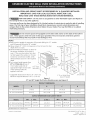
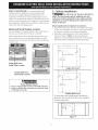
Your new wall oven has been designed to fit a limited variety of cutout sizes to make the job of installing
easier. The first step of your installation should be to measure your current cutout dimensions and
compare them to the cutout dimensions chart below for your model. You may find little or no cabinet
work being necessary.
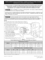
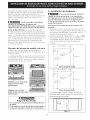
Do not remove spacers (if equipped) on the side walls and/or on the back of the built=in
oven. These spacers center the oven in the space provided. The oven must be centered to prevent
excess heat buildup that may result in heat damage or fire.
NOTES:
1. Basemust be capable of supporting 150 pounds (68 kg) for 27" models
and 200 pounds (90 kg) for 30" models•
2. Allow at least 21 " (53.3 cm) clearance in front of oven for door
depth when it is open.
3. Dimension G (cutout depth) is critical to
1" (2.5cm) ___
Min.
the proper installation of the built-in
• • _ C "_"_ _ --_,--- Hole
oven. If the oven decorative trim does ' ---
>.. _,<-J- TOr L.aDle
not butt against the cabinet or if noise l ,. _F_:_ :....... I /
is heard on convection models verify B _
..... ' , 273/16" I /
dimension G _o assure i_ is_ne required _:_ t69 1cm_ _ , -
..... _ ::::: \ , / :__ . I
depth. . ............... J_--- __-- ......... i (7.6 cm)
4. For a cutout he ght greater than ,_ / / -<<_] <J2':_z_-_--_ I
27W_6" (70 6 cm) add one 2" >< \\\ ,, 31 , _ _.¢_:-_ _
(5 cm) wide wood shim of Do:[-"_i_enortJ -_"_ _ua_cer (78,7 _m)_,
<
<.
\
--r
appropr ate he ght to each sde (seenotPe2' _Y_ _D/ p | [_ (_ "--1]_,/,,_ /
of the opening under the ......_ _'_C_ < (3.2 cm) "/
appliance side rails. A, __ Min,//
_q / Electrical
• " v Junction Box
Suggested distance from floor is31 (78.7 cm). 2" (5 cm) Wide Wood
Minimum required distance is 4 1/2"(11.4 cm) Spacerif Needed
Figure 1
27" and 30" Single Wall Ovens (Double ovens see Figure 2)
27" (68.6 cm) Wall Oven 27 (68.6) 29%6 (73.8) 24% (62.5) 24F2 (62.2)
30" (76.2 cm) Wall Oven 30 (76.2) 29%6 (73.8) 28_A (71.8) 24F2 (62.2)
27" (68.6 cm) Wall Oven 247/8 (63.2) 25Y4 (64.1) 23V2 (59.7) 27Y4 (69.2) 28V2(72.4) 27_h (68.9) Min
30" (76.2 cm) Wall Oven 28V2 (72.4) 29 (73.7) 23V2 (59.7) 27Y4(69.2) 28V2 (72.4) 30V8 (76.5) Min
All dimensions are in inches (cm).
Printed in United States P/N 318201512 (0711) Rev. G
English - pages 1-8
Espahol - p_iginas 9-16

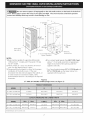
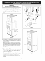
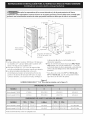
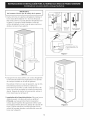
Do not remove spacers (if equipped) on the side walls and/or on the back of the built-in
oven, These spacers center the oven in the space provided. The oven must be centered to prevent
excess heat buildup that may result in heat damage or fire.
NOTES:
B
%.
Door Operi
(seenote 2)
i
/i@iiii
!
1" (2,5cm)
Min,
] "
_--Spacer
2"(5 cm) WideWood-
Spacerif Needed
1. Basemust be capable of supporting 300 pounds
(136 kg) for 27" models and 375 pounds (170 kg)
for 30" models.
2. Allow at least 21 " (53.3 cm) clearance in front of
oven for door depth when it is open.
3. Dimension G (cutout depth) is critical to the proper
installation of the built-in oven. If the oven
decorative trim does not butt against the cabinet, or
if noise is heard on convection models, verify
dimension G to assure it is according to the required
dimension.
Figure 2
3" (7.6 cm)
Max.
Junction Box
4. For a cutout height greater than 491A'' (125.1 cm)
add a 2" (5 cm) wide wood shim of appropriate
height to each side of the opening under the
appliance side rails.
* For Cutout height between 5113/16"(131.6 cm) and
51W16" (131.9 cm) use the larger inferior trim
supplied with the wall oven.
27" AND 30" DOUBLE OVENS (Single Ovens see Figure 1)
27" (68.6 cm) Wall Oven
30" (76.2 cm) Wall Oven
27 (68.6) 501/2(128.3) 248/s (62.5) 241/2(62.2)
30 (76.2) 501/2(128.3) 281/4(71.8) 241/2(62.2)
27" (68.6 cm) Wall Oven 247/s(63.2) 251/4(64.1) 231/2(59.7) 48%(124.1) 497/s(126.7) 27%(68.9) Min
30" (76.2 cm) Wall Oven 281/2 (72.4) 29 (73.7) 231/2(59.7) 487/s (124.1 ) 497/s (126.7)* 30% (76.5) Min
All dimensions are in inches (cm).
2

Important Notes to the Installer
1. Read all instructions contained in these installation
instructions before installing the wall oven.
2. Remove all packing material from the oven
compartments before connecting the electrical supply
to the wall oven.
3. Observe all governing codes and ordinances.
4. Besure to leavethese instructions with the consumer.
5. Oven door may be removed to facilitate installation.
6. THESEOVENS ARE NOT APPROVED FOR
STACKABLE OR SIDE=BY=SIDEINSTALLATION.
Important Note to the Consumer
Keep these instructions with your Owner's Guide for future
reference.
IMPORTANT SAFETY
INSTRUCTION
• Be sure your wall oven is installed and grounded
properly by a qualified installer or service
technician.
• This wall oven must be electrically grounded in
accordance with local codes or, in their absence,
with the National Electrical Code ANSI/NFPA
No.70= latest edition in United Sates, or with CSA
Standard C22.1, Canadian Electrical Code, Part 1, in
Canada.
Stepping, leaning or sitting on the
door of this wall oven can result in serious injuries
and can also cause damage to the wall oven.
Never use your wall oven for warming or heating
the room. Prolonged use of the wall oven without
adequate ventilation can be dangerous.
The electrical power to the oven must
be shut off while line connections are being made.
Failure to do so could result in serious injury or
death.
1. Carpentry
Refer to figure 1 or 2 for the dimensions applicable to
your appliance, and the space necessary to receive the
oven. The oven support surface may be solid plywood or
similar material, however the surface must be level from
side to side and from front to rear.
2. Electrical Requirements
This appliance must be supplied with the proper voltage
and frequency, and connected to an individual, properly
grounded branch circuit, protected by a circuit breaker or
fuse. To know the circuit breaker or fuse required by
your model, see the serial plate to find the wattage
consumption and refer to table A to get the circuit
breaker or fuse amperage.
ApplianceRating Protection ApplianceRating Protection
Watts Circuit Watts Circuit
240V recommended 208V recommende¢
lessthan 4800W 20A Lessthan 4100W 20A
4800W- 7200W 30A 4100W- 6200W 30A
7200W- %00W 40A 6200W - 8300W 40A
9600Wand + 50A 8300Wand+ 50A
Table A
Observe all governing codes and local ordinances
I. A 3-wire or 4-wire single phase 120/240 or 120/208
Volt, 60 Hz AC only electrical supply is required on a
separate circuit fused on both sides of the line (time-
delay fuse or circuit breaker is recommended). DO
NOT fuse neutral. Consideration must be given for a
combination built-in oven and cooktop refer to unit
serial plate of each.
NOTE: Wire sizes and connections must conform with
the fuse size and rating of the appliance in accordance
with the American National Electrical Code ANSI/NFPA
No. 70-latest edition, or with Canadian CSA Standard
C22.1, Canadian Electrical Code, Part 1, and local codes
and ordinances.
An extension cord should not be used
with this appliance. Such use may result in a fire,
electrical shock, or other personal injury. If you need
a longer power cord you can order for purchase a 10'
(3 m) power cord kit #903056-901 0 by calling the Sears
Parts & Repair Center at 1-800-4-MY-HOME ®.
2. This appliance should be connected to the fused
disconnect (or circuit breaker) box through flexible
armored or nonmetallic sheathed cable. The flexible
armored cable extending from the appliance should
be connected directly to the junction box. The
junction box should be located as shown in figure 1
or 2 and with as much slack as possible remaining in
the cable between the box and the appliance, so it
can be moved if servicing is ever necessary.
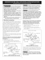
3. A suitable strain relief must be provided to attach
the flexible armored cable to the junction box.
In cold weather shipping and storage
conditions, make sure that oven is in final location at
least three (3) hours before switching on power.
Switching on power while oven is still cold may damage
the oven controls.
3. Adjusting Oven Height
Oven height can be adjusted with 2" (5 cm) wide wood
shims when needed to fit into an existing cabinet cutout
opening, when cutout height exceeds 2713/16"(70.6 cm)
for the single wall oven or 491/4"(125.1 cm) for the
double wall oven (see Figure 1 or 2). Place shims of
appropriate height beneath the oven side rails.
3

Electrical Shock Hazard
* Electrical ground is required on this appliance.
* Do not connect to the electrical supply until
appliance is permanently grounded.
* Disconnect power to the junction box before
making the electrical connection.
* This appliance must be connected to a grounded,
metallic, permanent wiring system, or a
grounding connector should be connected to the
grounding terminal or wire lead on the appliance.
* Do not use a gas supply line for grounding the
appliance.
Failure to do any of the above could result in a
fire, personal injury or electrical shock.
4. Electrical connection
It isthe responsibility and obligation of the consumer to
contact a qualified installer to assure that the electrical
installation is adequate and is in conformance with the
National Electrical Code ANSI/NFPA No. 70-latest
edition, or with CSA Standard C22.1, Canadian
Electrical Code, Part 1, and local codes and ordinances•
Electrical ground is required on this appliance.
These appliances are equipped with a copper conductor
flexible cable. If connection is made to aluminum house
wiring, use only special connectors which are approved
for joining copper and aluminum wires in accordance
with National Electrical Code and local codes and
ordinances•
These appliances are manufactured with a white neutral
power supply wire and a frame connected green or bare
copper grounding wire.
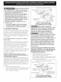
Where local codes permit connecting the appliance-
grounding conductor to the neutral (white) wire
(see figure 3):
1. Disconnect the power supply•
2. In the circuit breaker, fuse box or junction box:
connect appliance and power supply cable wires as
shown in Figure 3.
Cable from Power Supply
White Wire
tNeutralt4
RedWires_ i es]
Junction Box
-_""1 [",,White Wire
Ground Wire J/ _ (Neutral)
(Bare or Green U.L.-Listed Conduit
Wire)
Connector (or CSA listed)
Cable from appliance
Figure 3 - 3-WIRE GROUNDED JUNCTION BOX
Improper connection of aluminum
house wiring to copper leads can result in a short
circuit or fire. Use only connectors designed for
joining copper to aluminum, and follow the
manufacturer's recommended procedure closely.
You may not ground the oven
through the neutral (white) wire if oven is used in
a new branch circuit installation (1996 NEC), mobile
home, recreational vehicle, or where local codes do
not permit grounding through the neutral (white)
wire. When grounding through the neutral (white)
wire is prohibited, you must use a 4-wire power
supply cable. See Figure 4. Failure to heed this
warning may result in electrocution or other
serious personal injury.
If oven is used in a new branch circuit installation
(1996 NEC), mobile home, recreational vehicle, or
where local codes DO NOT permit grounding
through the neutral (white) wire (see figure 4):
1. Disconnect the power supply•
2. Separate the green (or bare copper) and white
appliance cable wires•
3. In the circuit breaker, fuse box or junction box:
connect appliance and power supply cable wires as
shown in Figure 4.
Cable from Power Supply
Ground Wire\
Red i_
Grou"ndWire X_;
(Bare or Green _I
Junction Box .....
hite Wire
White Wire
U.L.-Listed Conduit
Connector (or CSA listed)
Cable from appliance
Figure 4
4-WIRE GROUNDED JUNCTION BOX
DO NOT ground to a gas supply pipe. DO NOT connect
to electrical power supply until appliance is permanently
grounded• Connect the ground wire before turning on
the power (Figure 4).
If connecting to a 4-wire electrical
system (mobile homes), the appliance frame MUST
NOT be connected to the neutral wire of the 4-wire
electrical system.
4

NOTE TO ELECTRICIAN: The armored cable leads
supplied with the appliance are UL-recognized for
connection to larger gauge household wiring. The
insulation of the leads is rated at temperatures much
higher than temperature rating of household wiring. The
current carrying capacity of the conductor is governed by
the temperature rating of the insulation around the wire,
rather than the wire gauge alone.
Model and Serial Number Location
The serial plate is located along the interior side trim of
the oven and visible when the door is opened.
When ordering parts for or making inquires about your
oven, always be sure to include the model and serial
numbers and a lot number or letter from the serial plate
on your oven.
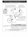
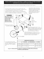
5. Cabinet Installation
_The wall oven can tip when the door is
open. The mounting brackets supplied with the
wall oven must be attached to the cabinet and the
appliance to prevent tipping of the wall oven and
injury to persons.
Mounting Brackets Installation Instructions
1. Unpack the wall oven. Remove the bottom trim taped
on the oven side panel. Find the 2 mounting brackets
and screws included in the literature package.
2. Install the mounting brackets in the wall cabinet as
shown on Figure 5. Note: Toprevent damage to
cabinet, it is recommended to drill 1/16" (0.16 cm) dia.
pilot holes before installing the mounting brackets.
Single Wall Oven
Serial Plate Location
Double Wall Oven
Serial Plate Location
Heavy Weight Hazard
Use 2 or more people to move and install wall oven.
Failure to follow this instruction can result in injury
or damage to the unit.
_F see figure 1_
kX,
Mounting Brackets _ H
see figure 1
22 3/16" *
(56.4 cm)
Single Wall ovens
L_F see figure 2_
kk"
I I T
Mounting Brackets _ H
see figure 2
43 5/8" *
(110.8 cm)
Double Wall ovens
• If wood shims are installed please calculate this
dimension from the top of the shim to the middle of
the mounting bracket.
Figure 5

i IMPORTANT
Do not lift the oven by the door handle.
3.Insert the oven into the cabinet opening. Slide oven
inward leaving 11/2"(3.8 cm) clearance between the
oven and front of cabinet (seeFigure 6). Pull the
armored cable through the hole for it in the cabinet and
toward the junction box while moving the appliance
inward.
1Y2" (3.8 cm)
clearance
between unit
Figure 6
4. Pushthe oven in and against the cabinet; the oven side
bracket will clip into the mounting bracket installed into
the side of cabinet.
Topull out the oven for servicing you must usethe two
tools supplied with the oven. Insert one tool into hole in
each side of oven frame. Holes are visible when door is
opened. After inserting tools pull the oven towards you
(see Figure 7).
5.Bottom Trim Installation:
(Note for the double wall ovens only: If the cutout height
is between 51W1J' (131.6 cm) and 511s/1J' (131.9 cm)
usethe larger bottom trim.)
Placethe top of the bottom trim over the side trim tabs
on each side of the oven below the oven door and fix it
using the 2 screws supplied in the mounting holes
located on each side trim below the oven frame (see
figure 8).
i
f
!/
Oven
side -.
trim _•
/
Oven
Mounting
bracketinstalled
in cabinet
Cabinet
Right
Side
Tool
supplied I
Mounting
bracket
released
Oven removed
from the cabinet
Hole where to
insert the tool
Figure 7
Screws
--Bottom Trim
Figure 8
6

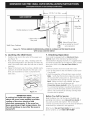
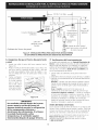
6.Fortypical under counter installation of an electric built-in oven see Figure below.
Only certain cooktop models may be installed over cer-
tain built-in electric oven models. Approved cooktops
and built-in ovens are listed by the MFG ID number and
product code (seethe insert sheet included in the litera-
ture package and cooktop installation instructions for the
dimensions).
To reduce the risk of
personal injury and
tipping of the wall
oven, the wall oven
must be secured to
the cabinet (s) by
mounting brackets,
Approx. 3"
(7.5 cm)
208/240 Volt junction
for built-in oven.
I
I
I
Cabinet side filler panels are
necessaryto isolate the unit
from adjoining cabinets. Cabinet
side filler height should allow for
installation of approved cooktop
models
36" Min.
(91.4 cm) Min.
Use3/4" (1.9 cm) plywood, installed
on two runners, flush with toe plate.
Basemust be capable of supporting
150 pounds (68 kg) for 27" models and
200 pounds (90 kg) for 30" models.
Cut an opening in wood base minimum 9" x 9"
(23 X 23 cm), 2" (5 cm) from left side filler
panel, to route armoured cable to junction box.
4 1/2" (11.5 cm) Max.*
* If no cooktop is installed directly over
the oven unit, 5" (12.7 cm) maximum
is allowed above the floor.
27" (68.6 cm) 247/8" (63.2 cm) Min. 23Y2" (59.7 cm) Min. 27¼" (69.2 cm) Min.
Wall Oven 25¼" (64.1 cm) Max. 281/2'' (72.4 cm) Max.
30" (76.2 cm) 281/2" (72.4 cm) Min. 27¼" (69.2 cm) Min.
Wall Oven 29" (73.7 cm) Max. 23Y2" (59.7 cm) Min. 281/2'' (72.4 cm) Max.
Figure 9 - TYPICAL UNDER COUNTER INSTALLATION OF A SINGLE ELECTRICBUILT-IN OVEN
WITH AN ELECTRICCOOKTOP MOUNTED ABOVE
7

Flexible Appliance
Wall Oven Cabinet
Cabinet sides or
filler panel
Flare
Union
120V/6OHz
Grounded
Outlet
Pressure
Regulator
Right Side
of Cabinet
Manual Shutoff Valve
(Tobe accessible for shut-off
valve operation)
Figure 10 =TYPICAL UNDER COUNTER INSTALLATION OF A SINGLE ELECTRICBUILT-INOVEN
WITH A GAS COOKTOP ABOVE
6. Leveling the Wall Oven
1. Install an oven rack in the center of the upper oven
(see Figure 11).
2. Place a level on the rack. Take 2 readings with the
level placed diagonally in one direction and then the
other. Use wood shims under the wall oven to level if
necessary.
3. Repeat in the lower oven if you have a double cavity
wall oven. If the level indicates that the rack is not
level, use wood shims to reach a compromise for
both ovens. ______.............................
Figure 11
7. Checking Operation
Your model isequipped with an Electronic Oven
Control. Eachof the functions has been factory
checked before shipping. However, it is suggested that
you verify the operation of the electronic oven controls
once more. Refer to the Use and Care Guide for
operation.
1. Remove all items from the inside of the oven.
2. Turn on the power to the oven (Refer to your Use &
Care Guide.)
3. Verify the operation of the electronic oven controls:
Bake - Verify that this function makes the oven hot.
20 seconds after turning oven on, open the door and
you should feel heat coming from the oven.
Broil - When the oven is set to BROIL,the upper
element in the oven should become red.
Convection (some models )-When the oven is set
for a convection baking or roasting, both elements
cycle on and off alternately and the convection fan
will run. The convection fan will stop running when
the oven door is opened.
IMPORTANT NOTE
A cooling fan inside the upper rear part
above the oven (some models) provides
cooling of the oven electrical and
electronic components. If the oven has
been operating at high temperatures, the
fan will continue to run after the oven is
turned off.
Before You Call for Service
Read the Before You Call for Service Checklist and
operating instructions in your Use and Care Guide. It
may save you time and expense. The list includes
common occurrences that are not the result of defective
workmanship or materials in this appliance.
Refer to your Use and Care Guide for Sears service
phone numbers, or call 1=800-4-MY-HOME ®.
8

LA INSTALACION Y EL SERVICIO DEBEN SER EFECTUADOS POP, UN INSTALADOR CAUFICADO.
IMPORTANTE: GUARDE ESTAS INSTRUCCIONES PARA USO DEL iNSPECTOR LOCAL DE
ELECTRICIDAD. LEA Y GUARDE ESTAS INSTRUCCIONES PARA REFERENCIA FUTURA.
PARA SU SEGURIDAD: No alrnanece ni utilice gasolina u otros vapores y liquidos inflarnables
en la proxirnidad de este o de cualquier otro artefacto.
El primer paso para su Jnstalaci6n debe de ser el de rnedir las dffnensiones de la apertura y cornpararlas con las
que se indican en el cuadro de dirnensJones del hueco de la fJgura 1. PosJblernente encontrar_ que algun
trabajo de carpinteria ser_ necesario.
No quite los separadores de los muros laterales o/y de la parte posterior del homo
empotrado. Estos espaciadores centran el homo en el espacio provisto. El homo debe estar centrado para
prevenir una concentracion excesiva de calor que podria resultar en daffos pot el calor o un incendio.
NOTAS:
1. Labase debe poder sostener 150 libras (68 kg) para los modelos 27"
y la base debe poder sostener 200 libras (90 kg) para los modelos 30". _.
2. Deje por Io menos 21 " (53.3 cm) de espacio libre para la profundidad 1" (2.5cm)
de la puerta cuando esta abierta.
Min
3. LadimensiOn G (profundidad del corte) I ' (_
est,1primordial para instalar correc- j_ -_---_' _ .... Orificio
C ara el
tamente el homo de pared Sleladorno _ _ _ -- ' _ _--_ P
• _ _-__ _t_ ....... Cable
de armazOn de homo no topa contra e _ _ .....
...... _ ......... H F _: :
armario o si escuche un ruido verifique / "---._
' ' a _-_ 27 3/16" "
si la dimensiOn G est,1en conformidad _%_
con a d mens 6n requer da _ _ff., _,,v . _!b .... ',
i. Para un corte de una a tura I "_' _ _i .... ';_---_.i. (7.6cm)
mayor que 27'3/,6'' (70,6 cm) : ,/J-- 31"* _<_ _=.}S-=<<...."----4..
agregar una cui_ade madera de ............. i .... I%x. (78.7 :m) I _ .__(/__
2" (5 cm) de ancho para ograr Puer-taAbierta _, _ Es_aciador ,I ff _'- ,._ _ i
(veala nota 2) _4 ] t_ 1
la altura aprop,ada a cada lado .......... _ ._ _ t."_¼,,
del orificio ubicado debajo de los .... ... '<_ _ I (3.2 cm) "1
" " --A "<- _ Mm /
neleslateralesdelaccesorlo. _ _'_ /Min" /C-ajaJ" tt eletrica
Distancia sugerida desde el suelo es 31 " (78.7 cm). Espaciadorde Maderade 2_ deempalme
La distancia minima requerida es 41/2" (11.4 cm). Figura I (5 cm) de ancho,siesnecesario
Hornos simples de Pared de 27" y 30" (Para hornos dobles, vet la Figura 2)
Homo de pared 27 (68.6) 27 (68.6) 29%6 (73.8) 24% (62.5) 241/2(62.2)
Homo de pared 30 (76.2) 30 (76.2) 29%6 (73.8) 281/4(71.8) 241/2(62.2)
Homo de pared 27 (68.6) 247/8(63.2) 251A (64.1) 231/2(59.7) 271A (69.2) 281/2(72.4) 27% (68.9) Min
Homo de pared 30 (76.2) 281/2(72.4) 29 (73.7) 231/2(59.7) 271/4(69.2) 281/2(72.4) 30% (76.5) Min
Todas las dimensiones sedan en pulgadas (cm).
Imprimido en los Estados Unidos P/N 318201512 (0711) Rev. G
English - pages 1-8
Espahol - p5ginas 9-16

No quite los separadores de los muros laterales o/y de la parte posterior del homo
empotrado. Estos espadadores centran el homo en el espado provisto. El homo debe estar centrado para
prevenir una concentraci6n excesiva de calor que podria resultar en da_os pot el calor o un incendio.
B
PuertaAbierta
(vea la nota 2)
.z --o D
.....\A.I
J
:_!{iiiiii_!iil
@,i!i!
i/i@i
1" (2,5cm)
Min,
1
48 5/8"
(123.5cm)
L 11V2"
1/ (29,2
__ Espaciad(
Z L
Orificio
parael
Caible
Espaciador de Madera de
2" (5 cm) de ancho, si es
necesario
3" (7.6 cm)
Max.
a eletrica de
empalme
NOTES:
1. Labase debe poder sostener 300 libras (136 kg) para
los modelos 27" y la base debe poder sostener 375 4.
libras (170 kg) para los modelos 30".
2. Deje por Io menos 21 " (53.3 cm) de espacio libre
para la profundidad de la puerta cuando esta abierta.
3. Ladimensi6n G (profundidad del corte) est,1
primordial para instalar correctamente el homo de *
pared. Si el adorno del armaz6n del homo no topa
contra el armario, o si escuche un ruido, verifique si
la dimensi6n G esbi en conformidad con la
dimensi6n requerida.
Para un corte de una altura mayor que 491A'' (125.1
cm) agregar una cufla de madera de 2" (5 cm) de
ancho para Iograr la altura apropiada a cada lado del
orificio ubicado debajo de los rieles laterales del
accesorio,
Para altura de corte entre 5113/16.' (131.6 cm) y
511s/16'' (131.9 cm), usar el corte grande inferior
que viene con el homo de pared.
Figura 2
HORNOS DOBLES DE 27" Y 30" (Para homos simples, vet la Figura 1)
Homo de pared 27 (68.6)
Homo de pared 30 (76.2)
27 (68.6)
30 (76.2)
501/2(128.3)
501/2(128.3)
24s/8 (62.5)
281/4(71.8)
241/2(62.2)
241/2(62.2)
Horno de pared 27 (68.6) 247/8 (63.2) 251/4 (64.1) 231/2(59.7) 487/s (124.1) 497/s (126.7) 27% (68.9) Min
Homo de pared 30 (76.2) 281/2 (72.4) 29 (73.7) 231/2(59.7) 487/s (124.1) 497/s (126.7)* 30% (76.5) Min
Todas lasdimensiones se dan en pulgadas (cm).
10

Notas importantes para el instalador
1.Lea todas las instrucciones contenidas en este manual
antes de instalar el homo.
2.Saque todo el material usado en el embalaje del
compartimiento del homo antes de conectar el suministro
electrico o de gas a la estufa.
3.Observe todos los codigos y reglamentos pertinentes.
4. Deje estas instrucciones con el consumidor.
5.La puerta del homo se puede retirar para facilitar la
instalacion.
6. ESTE HORNO NO ESTA APROBADO PARA LA
INSTALACION APILABLE O DE LADO A LADO.
Nota importante ai consumidor
Conserve estas instrucciones y el manual del usuario para
referencia futura.
INSTRUCCIONES
IIVlPORTANTES DE SEGURIDAD
* Asegurese de que su homo de pared sea instalado
y puesto a tierra de forrna apropiada pot un
instalador calificado o pot un tecnico de servicio.
* Este homo de pared debe set electricarnente
puesto a tierra de acuerdo con los c6digos locales
o, en su ausencia, con el C6digo Electrico Nacional
ANSI/NFPA No. 70-ultirna edicion en los Estados
Unidos, o el C6digo Electrico Canadiense CSA
Standard C22.1, Part 1, en Canada.
Pisar, apoyarse, o sentarse sobre la
puerta de este homo de pared puede causar serias
lesiones y da_os al homo de pared.
* Nunca use su homo de pared para calentar una
habitaci6n. El uso prolongado de la estufa sin la
ventilacion adecuada puede set peligroso.
La corriente electrica al homo debe
estar apagada rnientras se hacen las conexiones de
Iineas. Si no se apaga, da_os serios o la rnuerte
podrian resultar.
1. Carpinteria
Consulte la Figura 1 o la figura 2 para conocer las dimen-
siones pertinentes al modelo de su homo y al espacio
necesario en el que poner el homo. La superficie donde se
va a apoyar el homo debe de set de madera
contrachapada solida u otto material similar y, sobre todo,
la superficie tiene que estar a nivel, de lado a lado, y de
atr_is hacia adelante.
2. Requerirnientos Electricos
Se debe proveer el voltaje y la frecuencia apropiados a
este electrodom_stico, y conectarse a un circuito individual
correctamente puesto a tierra, protegido pot un interruptor
o un fusible. Para conocer el interruptor o fusible que
requirie su modelo, vea la placa serial para encontrar la
consomaci6n del vatiaje y refierase al cuadro A para
encontrar el amperaje del interruptor o fusible.
Grados de Vatios Se recomienda Grados de Vatios Se recomienda
del una protecci6n del una protecci6n
electrodomestico al circuito electrodomestico al circuito
240V 208V
Menosde4800W 20A Menosde4100W 20A
4800W-7200W 30A 4100W- 6200W 30A
7200W-9600W 40A 6200W-8300W 40A
9600Wy+ 50A 8300Wy+ 50A
Table A
Observe todos los codigos que gobiernan y
ordenanzas locales
1. Un cablede 3 o 4 alambres monof_isico 120/240 o 120/
208 voltios, 60 hertzios esla unica fuente el@ctricaque
requiere en un circuito separado en ambos lados de la
linea (serecomienda un fusible o un interruptor de retraso
de tiempo). No funda a cable neutro. Sedebe de tenet
precaucion al combinar un homo de pared y una cubierta,
refierase a la placa de seria de cada uno de los aparatos.
NOTA: Lostamahos y lasconexiones del alambre deben
conformarse con el tamaho del fusible y el grado de la
aplicaci6n de acuerdo con el c6digo El@ctricoNacional
Americano ANSI/NFPANo. 70- ultima edici6n, o con el
est_qndarCSA canadiense C22.1, c6digo el@ctrico
canadiense, parte 1, y c6digos y ordenanzas locales.
Wt_ No debe de utilizarse ningun tipo
de extension con este electrodomestico. Esto podria
resultar en fuego, choque electrico o lesiones
personales. Si usted necesita un cable mas largo, puede
ordernar un cable de 10" kit 903056-9010 Ilamando al
centro de Partes y Servicion Searsal 1-888-SU-HOGARsM.
2. Estoselectrodom_sticos se deben conectar con la caja de
fusibles desconectada (o interruptor) a trav_s del cable flex-
ible forrado armado o no-met_qlico.Elcable armado flexible
del electrodom_stico se debe conectar directamente a la
cajade emplames. Lacajade empalmes sedebesituar seg0n
Io mostrado enel cuadro 1; ysedebe dejar un tanto flojo el
cable entre el electrodom_stico y la caja de manera que la
unidad puede ser movida si es necesario darle
mantenimiento.
3.Se debe de proporcionar un retenedor de cable para unir
el cable armado flexible a la caja de empalmes.
En cuanto alas condiciones de despacho
y almacenamiento en el invierno, aseg0rese de que el
homo Ilegue a su destino final como m[nimo tres (3)
horas antes de encenderlo. Si se enciende el homo
cuando a0n est,1 fr[o, se pueden dahar los controles.
3. Ajuste de la altura del horno
La altura del homo se puede ajustar con cuhas de madera de
2" (5 cm) de ancho, donde sea necesario, para que quepa en
un gabinete o abertura existente, cuando la altura del corte es
superior a 2713/16" (70,6 cm) en el caso del homo 0nico de
pared o 491/4" (125.1 cm) en el caso del homo doble de pared
(vet la Figura 1 6 2). Colocar las cuhas de altura apropiada
debajo de los rieles laterales del homo.
11

Riesgodechoqueel_ctrico
• Una puesta a tierra se require en este aparato.
• No Io conecte a la corriente electrica hasta que
el aparato haya sido puesto a tierra.
• Desconecte la corriente electrica a la caja de
empalmes antes de hacer la conexi6n electrica,
• Este aparato debe estar conectado con un
sistema de alambres puesto en tierra, met_lico
y permanente o un conector de pueta a tierre
debe conectarse al terminal de puesta a tierra o
el alambre conductor en al aparato,
• No utilice el suministro de gas para hacer la
puesta a tierra,
La falta de cualquiera de las instrucdones
mendonadas podria resultar en un incendio,
choque electrico o lesiones personales,
4. Conexion electrica
El usuario tiene la responsabilidad personal y obligaciOn
de utilizar un instalador calificado, para asegurar que la
instalacion electrica est,1 hacha de forma adecuada y
est,1 conforme con el Codigo Electrico Nacional ANSI/
NFPA No. 70-01tima ediciOn en los Estados Unidos, o el
Codigo Electrico Canadiense CSA Standard C22.1, Part
1, en Canada1.
En este electrodomestico se necesita un cable de
toma a tierra,
Este electrodomestico viene equipado con un cable de
conexion de cobre. Si esto tuviera que conectarse a los
cables de aluminio de una casa, use solamente los
conectores especiales aprobados para empalmes de
cobre y aluminio, de acuerdo con el Codigo Electrico
Nacional y los reglamentos y codigos locales.
Este electrodomestico se ha fabricado con un cable para
el suministro de energia que tiene un alambre neutro de
color blanco y un alambre pelado de toma a tierra
conectado al armazon.
Donde los codigos locales permitan conectar el
conductor de puesta a tierra del electrodom_stico al
neutral (blanco) (vea figura 3):
(Un cordon flexible o cable de 3 conductores debe de ser
reemplazado con un cordon flexible o cable de 4 conducto-
res donde la conexiOn del conductor a tierra al neutro esta
prohibida en las nuevas instalaciones (1996 NEC), las casas
sobre ruedas, losvehiculos de recreaciOn o otras _ireas
donde los cOdigos locales no permiten la conexiOn a tierra
al neutro.)
1. Desconecte el suministro el_ctrico.
2. Enel interruptor autom_qtico, caja de fusibles o caja de
juntas: conectar el aparato y los cables residenciales
como semuestra en la figura 3.
12
Cable desde el suministro de energia
Alambredesnudo ¢ _ _,/_Alambre
: -. negros
e palmes
__j _ Alambre
AIc_m_verde/i _. desnudo
Conductor de uni6n
Cable de la estufa listado-UL (o CSA)
Figura 3 - CAJA DE EMPALMES
DE 3 ALAMBRES PUESTA A TIERRA
Una conexi6n incorrecta del
alambrado de aluminio con los conductores de cobre
puede resultar en un cortacircuito o incendio. Use
solamente los conectores diseEados para juntar el
cobre con el aluminio y siga exactamente el
procedimiento recomendado por el fabricante,
No se puede conectar a tierra el
homo a traves del cable neutral (blanco) si el homo
es usado en una instalaci6n de circuito de ramal
nuevo (1996 NEC), en una casa rodante, en un
vehiculo para recreaci6n o si los c6digos locales no
permiten la conexi6n a tierra a traves del cable
neutral (blanco), Si est_ prohibida la conexi6n a
tierra a trav_s del cable neutral (blanco), se debe
usar un cable de alimentaci6n de 4 hilos. Ver la
Figura 4, Si no se observa esta advertencia, esto
puede resultar en electrocuci6n o en otra lesi6n
personal grave,
Si el horno se usa en una instalacion de circuito de
ramal nuevo (1996 NEC), en una casa rodante, en un
vehiculo para recreation o si los codigos locales NO
permiten la conexion a tierra a traves del cable
neutral (blanco) (ver figura 4):
1. Desconecte el suministro electrico
2. Separe el alambre verde (o cobre desnudo) y el
alambre blanco del electrodomestico.
3. En el interruptor autom_itico, caja de fusibles o caja de
juntas:conectar el aparato y los cables residenciales
como se muestra en la figura 4.
Cable desde el suministro de energia
Alambre desnudo_--_
A,a mbre-----._L_
i r i?:
Alambre verde
o desnudo _!
Caja de empalmes
Cable de la estufa
lambre blanco
Alambre
"_ Conductor de union
listado-UL (o CSA)
Figura 4- CAJA DE EMPALMES
DE4 ALAMBRES PUESTA A TIERRA

NO conecte el alambre puesto a tierra a una tuberfa de
suministro de gas. NO conecte el suministro de energfa
electrica hasta que el electrodomestico haya sido
permanentemente puesto a tierra. Conecte el alambre de
puesto a tierra antes de enchufar pot primera vez el
electrodomestico.
Si est_ conectado a un sistema
electrico de 4 alambres, el armaz6n del
electrodomestico NO TIENE QUE estar conectado al
alambre neutro del sistema electrico de 4 alambres.
NOTA AL ELECTRICISTA: Los conductores de cable
blindados provistos con este artefacto son aprobados pot
UL para la conexion al alambrado de casa de un calibre
mayor. El aislamientode Iosconductoresesta calificado
para temperaturas mas altas que las del alambrado de la
casa. La capacidad decorriente del conductoresta
gobernada pot la calificacion de la temperatura del
aislamiento alrededor del alambre en vez de solamente
el calibre del alambre.
Ubicaci6n dei numero de modelo y de serie
La placa con el n0mero de serie est,1 ubicada en la
guarnicion interior lateral del homo y se puede ver cuando
se abre la puerta.
Cuando haga pedidos de repuestos o solicite informacion
con respecto a su homo, este siempre seguro de incluir
el n0mero de modelo y de serie y el n0mero o letra del
Iote de la placa de serie de su homo.
Modelos con un solo homo-
la placa de serie est_
ubicada aqui.
Modelos con un horno
doble- la plata de serie est_
ubicada aqui.
Peligro de Peso Pesado
* Use 2 personas o m_s para mover e instalar el homo
de pared.
* Si no cumple con esta instrucd6n, puede resultar
en lesiones pesonales o daEos al horno de pared
5. Instalacion dei Gabinete
El horno de pared puede inclinarse
cuando la puertaestaabierta. Lossoportes de
montaje que vienen con el homo de pared deben
de estar ajustadas al armario y al aparato para
evitar que el horno de pared se incline y ocasione
quemaduras graves,
Instrucdones de instalad6n de los soportes de
montaje
1. Desembalar el homo de pared. Extraer la guarniciOn
inferior con cinta al panel lateral del homo. Buscar las
dos mensulas antideslizables y los tornillos que se
incluyen en el paquete de literatura.
2. Instale los soportes de montaje como en la figura 5. Nota:
Para prevenir cualquier tipo de daho al cabinete es
recomendable perforar agujeros conn un diametro de
1/16" (0,16cm) antes de instalar los soportes de
montaje.
____1 Fvea figura 1_
.... XX...........
22 3/16" *
(56.4 cm)
[ .... 'r .... -X\-
H
vea figura 1
1
Horno de pared simple
____1 Fvea figura 2_
43 5/8" *
(110.8 cm)
H
vea figure 2
[ .... 'r .... -X\-
Homo de pared doble
* Si hay instaladas cu_as de madera, calcular esta
dimensi6n desde la parte superior de la cuba hasta el
medio del soporte de montaje.
i ''"-QJj
Figura 5
__ m
I
i
13

IMPORTANTENo levante el horno por la manija de la puerta.
3.Insertar el homo en la abertura del gabinete. Deslizar el
homo hacia dentro dejando 11/2"(3,8 cm) de espacio
libre entre el homo y la parte delantera del gabinete (ver
la Figura 6). Empujar el cable blindado a trav_s del
orificio del gabinete y hacia la caja de paso mientras se
desliza el accesorio hacia adentro.
"_1 1/2" (3.8 cm)
distancia entre la
unidad y el gabinete
Figura 6
4. Empujar el homo hacia adentro yen contra del gabinete;
la m_nsula lateral del homo enganchar_i en los soportes
de montaje instalados en el lado del gabinete.
Paraextraer el homo en caso de reparaciOn, usar lasdos
herramientas provistas con el homo. Insertar una
herramienta en el orificio a cada costado del marco del
homo. Losorificios se pueden ver cuando la puerta est_q
abierta. Despu_s de insertar las herramientas, extraer el
homo hacia fuera (ver la Figura 7).
5.InstalaciOn de la GuarniciOn Inferior (S01opara hornos
dobles de pared: si la altura del corte esde 51,3/,6"
(131,6cm), usar la guarniciOn inferior m_qsgrande.)
Colocar la parte superior de la guarniciOn inferior sobre
las leng0etas laterales del homo, debajo de la puerta del
homo, y fijarlas usando los2 tornillos provistos con los
orificios de montaje ubicados a cada lado del marco del
homo (ver la Figura 8).
/_ Soporte de
. I montaje
ra,c,ket_ Iinstalado en el
ael I I gabinete
horn? I,_
_hinete
Homo Lateral
IL derecho
},Lherram ienta
........I_ incluida
soporte de
montaje
liberado
Horno retirado
del gabinete
Introduzca la
herramienta que trae
el electrodom6stico en
el hoyo.
Figura 7
Tornillos
-- Guarnici6n
Inferior
Figura 8
14

6. Para una instalacion tfpica de un horno electrico incorporado debajo del mostrador, ve_ise la figura 8.
S61o ciertos modelos de tapas de cocina se pueden instalar sobre
ciertos modelos de hornos electricos empotrados. Las tapas de cocina
y los hornos empotrados se mencionan pot su n0mero de
identificaci6n MFG ID y c6digo de producto (vet la planilla que se
incluye en el paquete de literatura y las instrucciones de instalaci6n
de la cocina donde est_in detalladas las dimensiones).
Los paneles de relleno laterales del
gabinete son necesarios para aislar la
unidad de los gabinetes adyacentes.
La altura del relleno lateral del
gabinete debe permitir la instalaci6n
de modelos de tapas de cocina
aprobados.
Para reducir e[ riesgo de
lesiones persona[es y
indinacion de[ homo de
pared, este debe
asegurarse a los
gabinetes mediante
soportes de montaje.
208/240 caja de empalme
para hornos de pared
Approx. 3"
(7.5 cm)
36" Min.
(91.4 cm) Min.
F
Instale contrachapado de 3/4" (1.9 cm)
sobre dos correderas, nivelado con la parrilla
inferior. La base debe poder sostener 150
libras (68 kg) para los modelos 27" y 200
libras (90 kg) para los modelos 30".
Corte una abertura de 9" X 9"(23 cm X 23 cm)
(minimo) en el fondo del contrachapado, a 2" (5 cm)
del lado izquierdo del panel Ilenador, para poder
encaminar el cable a la caja de empalme.
4 1/2" (11.5 cm) Max.*
* Si no se instala ninguna tapa de
cocina directamente sobre la unidad
del homo, sepermite un espacio
m_qximode 5" (12,7 cm) sobre el
piso.
DIMENSIONES DEABERTURA
F. ANCHURA G. PROFUNDIDAD H. ALTURA
i ,, ,,
i 27 (68.6 cm) 247/8'' (63.2 cm) Min. 23Y2 (59.7 cm) Min. 27¼" (69.2 cm) Min.
iHorno de pared 25¼" (64.1 cm) Max. 281/2'' (72.4 cm) Max.
30" (76.2 cm) 281/2'' (72.4 cm) Min. 23Y2" (59.7 cm) Min. 27¼" (69.2 cm) Min.
IHorno de pared 29" (73.7 cm) Max. 281/2'' (72.4 cm) Max.
Figura 8- INSTALACION T[PICA DEBAJO DE LA MESADA DE HORNO SIMPLE EMPOTRADO
CON TAPA DECOCINA MONTADA
15

Conector flexible r
artefactos
Ladosdel
gabinete o panel
Ilenador
I
18"(45.7 cm) Max. ----'_I
I
3 4"(10_cm)
Lado
"' Tomacorriente derecho del
puesto a tierra gabinete
Adaptor de 120Voltios
de gas 60Hz
Regulador de
presi6n
V_ilvula de clerre manual
Gabinete del homo de pared (para tener acceso a la wilvula
de cierre manual)
Figura 9 = INSTALACION T{PICA PARA UNA ESTUFA DE GAS ENCIMA
DE UN HORNO DE PAREDINSTALADO DEBAJO DELMOSTRADOR
6. Asegurese de que el horno de pared esta
a nivei
1. Instale una rejilla al centro del homo superior (yea la
Figura 10).
2. Ponga un nivel pot encima de la rejilla. Lea 2 veces, una
vez con el nivel a la posicion de lado a lado, y otra vez
de atr_is hacia adelante. Utilice trozo de madera o cu-
has pot debajo del homo de pared para nivelar, si sea
necesario.
3. Vuelve a empezar .............. _-:_
en el homo inferior.
Si el nivel muestra
que la rejilla no i
esta a nivel, utilice
trozo de madera o
cuhas para compo-
net ambos hornos.
Figura 10
IMPORTANTE
Un ventilador ubicado dentro de la parte
trasera superior arriba del homo (en
algunos modelos) permite la refrigeracibn
de los componentes el_ctricos y
electrbnicos de enfriamiento. Si el homo
ha estado funcionando a altas
temperaturas, el ventilador seguir&
funcionando despu_s de apagar el homo.
7. Verificacion dei funcionamiento
Su modelo est.1 equipado con un Control Electronico de
Horno. Cada una de las funciones ha sido controlada en
f_ibrica antes del despacho. Sin embargo, le sugerimos
verificar el funcionamiento de los controles electronicos
una vez m_is. Consulte la Guia de Uso y Cuidado para
ver el funcionamiento del homo.
1,
2.
3.
Extraer todos los elementos de la parte interior del
horno.
Encender el horno (Consular la Gu[a de Uso y Cuidado.)
Verificar el funcionamiento de los controles electronicos
del horno:
Hornear - Verificar que esta funcion caliente el horno.
Veinte minutos despues de encender el horno, abrir la
puerta y ver si se siente que el calor emana desde su
interior.
Asar- Cuando se pone el homo para asar, el
elemento de arriba del homo debe de ponerse rojo.
Convecci6n (algunos modelos) - Cuando se configura
el homo para horneado o asado pot conveccion, los dos
elementos se encienden y apagan en forma alterna y se
enciende el ventilador. El ventilador de conveccion
dejar_i de funcionar cuando se abre la puerta del homo
durante el horneado o asado pot conveccion.
Antes de ilamar al servicio
Lea la seccion Lista de Antes de Ilamar en su Manual del
Usuario. Estole podr_i ahorrar tiempoygastos. Esta lista
incluye ocurrencias comunes que no son el resultado de
defectos de materiales o fabricacion de este artefacto.
Lea la garant[a y la informacion sobre el servicio en su
Manual del Usuario para obtener el n0mero de
telefono gratuito y la direccion del servicio o llama
1-888-SU-HOGAR sM.
16
-
 1
1
-
 2
2
-
 3
3
-
 4
4
-
 5
5
-
 6
6
-
 7
7
-
 8
8
-
 9
9
-
 10
10
-
 11
11
-
 12
12
-
 13
13
-
 14
14
-
 15
15
-
 16
16


Kenmore 4803 Guía de instalación
- Categoría
- Hornos
- Tipo
- Guía de instalación
en otros idiomas
- English: Kenmore 4803 Installation guide
Artículos relacionados
-
Kenmore 79048763900 Guía de instalación
-
Kenmore 79048083000 Guía de instalación
-
Kenmore 79048173002 Guía de instalación
-
Kenmore Electric Wall Oven Guía de instalación
-
Kenmore Pro FGEW3065PFD Guía de instalación
-
Kenmore 79044383700 Guía de instalación
-
Kenmore 79047849407 Guía de instalación
-
Kenmore 79047733404 Guía de instalación
-
Kenmore 79048843901 Guía de instalación
-
Kenmore 79040619802 Guía de instalación
Otros documentos
-
Frigidaire GLEB30S8CBB Guía de instalación
-
Electrolux EW27EW55GB2 Guía de instalación
-
Frigidaire FEB398CETB Guía de instalación
-
Electrolux EW27EW55GS8 Guía de instalación
-
-
Frigidaire CFEW3025LSA Guía de instalación
-
-
-
Frigidaire FGEW3045KBA Guía de instalación
-
Frigidaire FPMC3085KFA Guía de instalación