Kenmore Electric Wall Oven Guía de instalación
- Categoría
- Hornos
- Tipo
- Guía de instalación

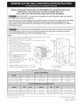
iNSTALLATiON AND SERVICE MUST BE PERFORMED BY A QUALiFiED iNSTALLER.
IMPORTANT: SAVE FOR LOCAL ELECTRICAL iNSPECTOR'S USE.
READ AND SAVE THESE iNSTRUCTiONS FOR FUTURE REFERENCE.
FOR YOUR SAFETY: Do not store or use gasohne or other flammabJe vapors and Jiquids in
the vicinity of this or any other appliance.
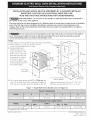
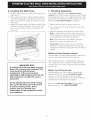
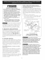
Your new wall oven has been designed to fit a limited variety of cutout sizes to make the job of installing
easier. The first step of your installation should be to measure your current cutout dimensions and
compare them to the cutout dimensions chart beJow for your model You may find Jittle or no cabinet
work being necessary.
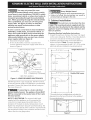
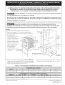
Do not remove spacers (if equipped) on the side walls and/or on the back of the built-in
oven. These spacers center the oven in the space provided. The oven must be centered to prevent
excess heat buiJdup that may result in heat damage or fire.
NOTES:
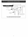
1. Cutout base must be capable of supporting 200 pounds (90 kg). _]T-.___
2. Allow at least 21 " (53,3 cm) clearance in front 1" (2.5 cm) - ' "_--__-----_ _
of oven for door depth when it is open. Min. _-
3. Dimension G (cutout
/
depth) is critical to the _ <L
proper installation of the _ _C. -._ _ -.....
. . .._ _.._. / ._, Hole
built-In oven. If the oven " F-'_ _... -_G LL- , ....
. . "_--._._,._ .--_ : TOF _able
decorative trim does not / _ --.:.... ; /
, , /
butt against the cabinet R 1_" H F _
. . . _ L.I ._ _J
or If noise IS heard on , i
cm) i ,,
convection models verify i _;__ 3
dimension G to assure it is I ";_ _" .'- ""-- t7 6 cm'
the required depth. "_. _ _ I,,_-" _ /, {..,_-'-;_H:_----._ '] '
Doo;Open _ ............./I Spacer I r_ _. _" _ [
(see note 2).,.. ................ /D t _ _ _] 1/,4,, _ '
""-... "_-_ _ (3.2 cm) "1
A _ _ _-_-_ Min.Jn./_,/ ,
2"cmlWideWood-- a'
4. For a cutout height greater than 27W_?' (70.6 cm) add Spacerif Needed V Junc!:lon !_OX
one2"(5cm) wide wood shim of appropriate height to * Suggested distance from floor is 31"(78.7cm).
each side of the opening under the appliance side rails. Minimum required distance is4 1/2"(11.4 cm)
Figure 1 - Single Wall Ovens (Double ovens see Figure 2)
!!_;!_i_!_i_!_i_!_i_!_i_!_i_!_i_!_i_!_i_!_i_!_i_!_i_!_i_!_i_!_i_!_i_!_i_!_i_!_i_!_i_!iiiii(_iii_ili_ii__i,if!f_!i_ii_ii_ii_ii_iiiiiiiiiiiiiliiliiiiiii_iili_!!_i'!_i!i_i!;i!;i!;i!i_i!;i!;i!;i!i_i!;i!;i!;i!i_i!;i!;i!;i!i_i!;i!;i!;i!i_i!;i!;i!;i!i!iiiiil_iri!_i!_i!r i!_i!_i!_i_iiiiiiiiiiiiiiiiiiiii_i_iiii!!!iii_iii_iii_iii_iii_iii_iii_iii_iii_iii_iii_iii_iii_iii_iii!_{!
30" (76.2 cm) Wall Oven 30 (76.2) 29V_ (73.8) 28¼ (71.8) 24Y_ (62.2)
30" (76,2 cm) Wall Over] 28Y2 (72.4)
All dimensions are in inches (cm).
Printed in United States
29 (73.7) 23B (59.7) 27¼ (69.2) 28Y2 (72.4) 30I/s (76.5) Min
P/N 318201522 (0602) Rev. A
English - pages 1-10
Espahol - paginas 11-20

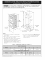
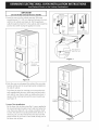
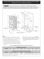
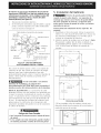
Do not remove spacers (if equipped) on the side walls and/or on the back of the built-in
oven. These spacers center the oven in the space provided. The oven must be centered to prevent
excess heat buildup that may result in heat damage or fire.
I
1" (2,5 cm)
Min.
- 4._
,
(DeOeOrnoO1_2i" "" (29'_1_'t) _----
"'"'"'"'"" "" A _/ Spacer2" Spacer ii(5 cm f)__/id Need e_
NOTES:
1. Cutout base must be capable of supporting 300
pounds (136 kg).
2. Allow at least 21 " (53.3 cm) clearance in front of
oven for door depth when it is open.
3. Dimension G (cutout depth) is critical to the proper
installation of the built-in oven. If the oven
decorative trim does not butt against the cabinet, or
if noise is heard on convection models, verify
dimension G to assure it is according to the required
dimension.
Hole for
//_ble
1¼"
cm)
3" (7.6 cm)
Max.
Junction Box
4. For a cutout height greater than 491/4"(125.1 cm)
add a 2" (5 cm) wide wood shim of appropriate
height to each side of the opening under the
appliance side rails.
Figure 2- DOUBLE OVENS (Single Ovens see Figure 1)
T
30" (76,2 cm) Wall Oven 281/2(72"4) / 29(73.7)
All dimensions are in inches (cm).
23Y2 (59.7)
48% (124. I) I 49% (I 26.7)
30I/8 (76,5) Min

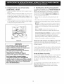
Important Notes to the Installer
1. Readall instructions contained in these installation
instructions before installing the wall oven.
2. Remove all packing material from the oven
compartments before connecting the electrical supply
to the wall oven.
3. Observe all governing codes and ordinances.
4. Be sure to leavethese instructions with the consumer.
5. Oven door may be removed to facilitate installation.
6. THESE OVENS ARE NOT APPROVED FOR
STACKABLE OR SIDE-BY-SIDE INSTALLATION.
Important Note to the Consumer
Keep these instructions with your Owner's Guide for future
reference.
IMPORTANT SAFETY
2. Electrical Requirements
This appliance must be supplied with the proper voltage
and frequency, and connected to an individual, properly
grounded branch circuit, protected by a circuit breaker or
fuse. To know the circuit breaker or fuse required by
your model, see the serial plate to find the wattage
consumption and refer to table A to get the circuit
breaker or fuse amperage.
Appliance Protection Appliance Protection
RatingWatts Circuit RatingWatts Circuit
240V recommended 208V recommended
lessthan 4800W 20A Lessthan 4100W 20A
4800W- 7200W 30A 4100W-6200W 30A
7200W- 9600W 40A 6200W- 8300W 40A
9600Wand+ 50A 8300Wand+ 50A
INSTRUCTIONS
* Be sure your wall oven is installed and grounded
properly by a qualified installer or service
technician.
* This wall oven must be electrically grounded in
accordance with local codes or, in their absence,
with the National Electrical Code ANSI/NFPA
No.70- latest edition in United Sates, or with CSA
Standard C22.1, Canadian Electrical Code, Part 1, in
Canada.
Table A
Observe all governing codes and local ordinances
I.A 3-wire or 4-wire single phase 120/240 or 120/208
Volt, 60 Hz AC only electrical supply is required on a
separate circuit fused on both sides of the line (red and
black wires). A time-delay fuse or circuit breaker is
recommended. DO NOTfuse neutral (white wire). Only
certain cooktop models may be installed over certain
built-in electric oven models. Approved cooktops and
built-in ovens are listed by the MFG ID number (see
the insert sheet included in the literature package).
Stepping, leaning or sitting on the
door of this wall oven can result in serious injuries
and can also cause damage to the wall oven.
• Never use your wall oven for warming or heating
the room. Prolonged use of the wall oven without
adequate ventilation can be dangerous.
The electrical power to the oven must
be shut off while line connections are being made.
Failure to do so could result in serious injury or
death.
1. Carpentry
Refer to figure 1 or 2 for the dimensions applicable to
your appliance, and the space necessary to receive the
oven. The oven support surface (cutout base) may be
solid plywood or similar material, however the surface
must be level from side to side and from front to rear.
NOTE: Wire sizes and connections must conform with
the fuse size and rating of the appliance in accordance
with the American National Electrical Code ANSI/NFPA
No. 70-latest edition, or with Canadian CSA Standard
C22.1, Canadian Electrical Code, Part 1, and local codes
and ordinances.
An extension cord should not be used
with this appliance. Such use may result in a fire,
electrical shock, or other personal injury. If you need
a longer power cord you can purchase a 10' (3 m) power
cord kit #903056-9010 by calling the Sears Parts &
Repair Center at 1-800-4-MY-HOME ®.
2. These appliances should be connected to the fused
disconnect (or circuit breaker) box through flexible
armored or nonmetallic sheathed cable. The flexible
armored cable extending from the appliance should
be connected directly to the junction box. The
junction box should be located asshown in Figure I
or Figure 2 and with as much slack as possible
remaining in the cable between the box and the
appliance, so it can be moved if servicing is ever
necessary.
3. A suitable strain relief must be provided to attach
the flexible armored cable to the junction box.

Electrical Shock Hazard
• Electrical ground is required on this appliance.
• Do not connect to the electrical supply until
appliance is permanently grounded.
• Disconnect power to the junction box before
making the electrical connection.
• This appliance must be connected to a
grounded, metallic, permanent wiring system,
or a grounding connector should be connected
to the grounding terminal or wire lead on the
appliance.
• Do not use a gas supply line for grounding the
appliance.
Failure to do any of the above could result in a
fire, personal injury or electrical shock.
In cold weather shipping and storage
conditions, make sure that oven is in final location at
least three (3) hours before switching on power.
Switching on power while oven is still cold may damage
the oven controls.
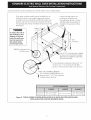
Where local codes permit connecting the appliance
cable ground wire to the power supply cable
neutral (white) wire (see figure 3):
I. Disconnect the power supply.
2. In the circuit breaker, fuse box or junction box:
connect appliance and power supply cable wires as
shown in Figure 3.
Cable from Power Supply
White Wire
(Neutral)
\
Red
Wires
Wires ]
Box
Wire
(Neutral)
Ground Wire U,L-Listed Conduit
(Bare or Green Wire) Connector (or CSA listed)
(able from appliance
Figure 3 - 3-WIRE GROUNDED JUNCTION BOX
3. Adjusting Oven Height
Oven height can be adjusted with 2" (5 crn) wide wood
shims when needed to fit into an existing cabinet cutout
opening, when cutout height exceeds 2713/16'' (70.6 cm)
for the single wall oven or 491A'' (125.1 cm) for the
double wall oven (see Figure I or 2). Place shims of
appropriate height beneath the oven side rails.
Improper connection of aluminum
house wiring to copper leads can result in a short
circuit or fire. Use only connectors designed for
joining copper to aluminum, and follow the
manufacturer's recommended procedure closely.
4. Electrical connection
It isthe responsibility and obligation of the consumer to
contact a qualified installer to assure that the electrical
installation is adequate and is in conformance with the
National Electrical Code ANSl/NFPA No. 70-latest
edition, or with CSA Standard C22.1, Canadian
Electrical Code, Part I, and local codes and ordinances.
Electrical ground is required on this appliance.
These appliances are equipped with a copper conductor
flexible cable. If connection is made to aluminum house
wiring, use only special connectors which are approved
for joining copper and aluminum wires in accordance
with National Electrical Code and local codes and
ordinances.
These appliances are manufactured with a white neutral
power supply wire and a frame connected green or bare
copper grounding wire.

You may not ground the oven
through the neutral(white)wire ifoven isused in
a new branch circuitinstallation(1996 NEC),mobile
home, recreationalvehicle,or where localcodes do
not permit grounding through the neutral(white)
wire.When grounding through the neutral(white)
wire is prohibited, you must use a 4-wire power
supply cable. See Figure 4. Failure to heed this
warning may result in electrocution or other
serious personal injury.
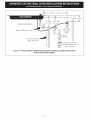
if oven is used in a new branch circuit installation
(1996 NEC), mobile home, recreational vehicle, or
where local codes DO NOT permit connecting the
appliance cable ground wire to the power supply
cable neutral (white) wire, you must use a 4-wire
power supply cable (see figure 4):
I. Disconnect the power supply.
2. In the circuit breaker, fuse box or junction box:
connect appliance and power supply cable wires as
shown in Figure 4.
Heavy Weight Hazard
• Use 2 or more people to move and install wall oven.
• Failure to follow this instruction can resumt in
personam injury or damage to the unit.
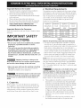
5. Cabinet Installation
The wall oven can tip when the door
is open, The mounting brackets supplied with the
wall oven must be attached to the cabinet and the
appliance to prevent tipping of the wall oven and
injury to persons.
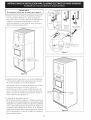
Mounting Brackets Installation Instructions
I. Unpack the wall oven. Remove the lower trim taped
on the oven side panel. Find the 2 mounting brackets
and screws included in the literature package.
2. Install the mounting brackets in the wall cabinet as
shown on Figure 5. Note: Toprevent damage to
cabinet, it is recommended to drill 1/16" (0.16 cm) dia.
pilot holes before installing the mounting brackets.
Cable from Power Supply
Ground Wire
Wire
Wires
Ground Wire
(Bare or
Wire)
Junction Box
U.L-Listed Conduit
Connector (or CSA listed)
Cable from appliance
Figure 4 - 4-WIRE GROUNDED JUNCTION BOX
DO NOT ground to a gas supply pipe. DO NOT connect
to electrical power supply until appliance is permanently
grounded. Connect the ground wire before turning on
the power (Figure 4).
If connecting to a 4-wire electrical
system (mobile homes), the appliance frame MUST
NOT be connected to the neutral wire of the 4-wire
electrical system.
NOTE TO ELECTRICIAN: The armored cable leads
supplied with the appliance are UL-recognized for
connection to larger gauge household wiring. The
insulation of the leads is rated at temperatures much
higher than temperature rating of household wiring. The
current carrying capacity of the conductor is governed by
the temperature rating of the insulation around the wire,
rather than the wire gauge alone.
Single Wall ovens
I_F see figure 1_
kets
H
see figure 1
22 3/16" *
(56.4 cm)
a a
a i
a a
a i
a a
L........ _\ ............ I
______ F see figure 2_ Double Wall ovens
.... Xk -i
' 'm
I a
Mounting Brackets aa H
see figure 2
43 5/8" *
(110scm)
a a
a i
a a
a i
a a
L........ _,\............ I
• If wood shims are installed please calculate this
dimension from the top of the shim to the middle of
the mounting bracket.
m
Figure 5

IMPORTANT
Do not lift the oven by the door handle.
3.Insert the oven into the cabinet opening. Slide oven
inward leaving 11/2"(3.8 cm) clearance between the oven
and front of cabinet (seeFigure 6). Pull the appliance
cable through the hole for it in the cabinet and toward the
junction box while moving the appliance inward.
"" Y2" (3.8 cm)
clearance
between unit
Figure 6
4.Push the oven in and against the cabinet; the oven side
bracket will clip into the mounting bracket installed into
the side of cabinet.
Topull out the oven for servicing you must use the two
tools supplied with the oven. Insert one tool into hole in
each side of oven frame. Holes are visible when door is
opened. After inserting tools pull the oven towards you
(see Figure 7).
5.Lower Trim Installation:
Fix the lower trim in place using the 2 screws supplied in
the mounting holes located on each side trim below the
oven frame (seefigure 8). Use a long screwdriver shaft
to reach the side trim mounting holes below the door. If
necessary,you can also remove the oven door (seethe
proper section in your Use& Care Guide) to help you fix
the lower trim in place.
supplied
Mounting
bracket
released
Oven removed
from the cabinet
Hole where to
insert the tool
Figure 7
Figure 8

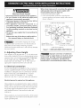
6.Fortypicalundercounterinstallationofanelectricbuilt-inovenseeFigurebelow.
Onlycertaincooktopmodelsmaybeinstalledovercer-
tainbuilt-inelectricovenmodels.Approvedcooktops
andbuilt-inovensarelistedbytheMFGIDnumberand
productcode(seetheinsertsheetincludedinthelitera-
turepackageandcooktopinstallationinstructionsforthe
dimensions).
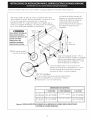
To reduce the risk of
personal injury and
tipping of the wall
oven, the wall oven
must be secured to
the cabinet (s) by
mounting brackets.
208/240 Volt junction box.
for built-in oven.
Approx. 3"
(7.5 cm)
Cabinet side filler panels are
necessaryto isolate the unit
from adjoining cabinets. Cabinet
sidefiller height should allow for
installation of approved cooktop
models
36" Min.
(91.4 cm) Min.
Use3/4" (1.9 cm) plywood, installed
on two runners, flush with toe plate.
Basemust be capable of supporting
200 )ounds (90 kg).
Cut an opening m wood base minimum 9" x 9"
(23 X 23 cm), 2" (5 cm) from left side filler
panel, to route armoured cable to junction box,
4-1/2" (11.5 cm) Max. distance*
* If no cooktop isinstalled directly over
the oven unit, 5" (12.7 cm) maximum
is allowed above the floor.
Figure 9 - TYPICAL UNDER COUNTER INSTALLATION OF A SINGLE ELECTRICBUILT-IN OVEN
WITH AN ELECTRICCOOKTOP MOUNTED ABOVE

FigureI0-TYPICAL UNDER COUNTER INSTALLATION OFA SINGLE ELECTRICBUILT-INOVEN
WITH A GAS COOKTOP ABOVE

6. Leveling the Wall Oven
I. Install an oven rack in the center of the upper oven
(see Figure 11).
2. Place a level on the rack. Take 2 readings with the
level placed diagonally in one direction and then the
other. Use wood shims under the wall oven to level
if necessary.
3. Repeat in the lower oven if you have a double cavity
wall oven. If the level indicates that the rack is not
level, use wood shims to reach a compromise for
both ovens.
Figure 11
IMPORTANT NOTE
A cooling fan inside the upper rear part
above the oven provides cooling of the
oven electrical and electronic
components, If the oven has been
operating at high temperatures, the fan
will continue to run after the oven is
turned off,
On the double wail oven, both cooling
fans can be ON when one of the ovens
is used in cleaning mode. This is
normal, This is to provide cool
temperature to the components inside
your appliance,
7. Checking Operation
Your model is equipped with an Electronic Oven
Control. Each of the functions has been factory checked
before shipping. However, it is suggested that you verify
the operation of the electronic oven controls once more.
Refer to the Use and Care Guide for operation.
.
2.
Remove all items from the inside of the oven.
Turn on the power to the oven (Refer to your Use &
Care Guide.)
Verify the operation of the electronic oven controls:
Bake - Verify that this function makes the oven hot.
20 seconds after turning oven on, open the door and
you should feel heat coming from the oven.
Broil - When the oven is set to BROIL, the upper
element in the oven should become red.
Convection-When the oven is set for convection
baking or roasting the convection fan will run. The
convection fan will stop running when the oven door is
opened.
Model and Serial Number Location
The serial plate is located along the interior side trim of
the oven and visible when the door is opened.
When ordering parts for or making inquires about your
oven, always be sure to include the model and serial
numbers and a lot number or letter from the serial plate
on your oven.
Before You Call for Service
Read the Before You Call for Service Checklist and
operating instructions in your Use and Care Guide. It
may save you time and expense. The list includes
common occurrences that are not the result of defective
workmanship or materials in this appliance.
Refer to your Use and Care Guide for Sears service
phone numbers, or call 1-800-4-MY-HOME ®.

Notes
10

LAINSTALACION Y EL SERVICiO DEBEN SER EFECTUADOS POR UN INSTALADOR CALIFICADO,
IMPORTANTE: GUARDE ESTAS INSTRUCCIONES PARA USO DEL iNSPECTOR LOCAL DE
ELECTRICiDAD, LEA Y GUARDE ESTAS INSTRUCCIONES PARA REFERENCiA FUTURA,
PARA SU SEGURIDAD: No almanece ni utilice gasolina u otros vapores y liquidos inflamables
en la proximidad de este o de cualquier otro artefacto.
El primer paso para su instaladbn debe de set el de medir las dimensiones de la apertura y compararlas con las
que se indkan en el cuadro de dimensiones del hueco de la flgura 1. Posiblemente encontrara que algun
trabajo de carpinteria sera necesario.
No quite los separadores de los muros laterales o/y de la parte posterior del homo
empotrado. Estos espaciadores centran e] homo en el espado provisto. E] homo debe estar centrado para
prevenir una concentrad6n excesiva de caJor que podria resu]tar en daSos pot eJcaJor o un incendio.
NOTAS:
1. La base debe poder sostener 200 libras (90 kg).
2. Deje por Io menos 21 " (53.3 cm) de espacio libre
para la profundidad de la puerta cuando esta abierta.
3. La dimension G
(profundidad del corte) _ C
esta primordial para f_
instalar correc-tamente el
/
horno de pared. Siel
adorno del armaz6rl del B
homo no topa contra el
armario, o si escuche un
ruido, verifique si la
dimensiOn G esta
erl conformidad <............
con la dimensi6n PuertaAbierta
requerida. (vea la nota 2)
1" (2,5 cm)
Min.
H
27 3/16" /
(69,1 cm)
31 "*
(78.7
Espaciador
Espaciador de Madera de 2"
(5 cm) de ancho, sies necesario -
Orificio
para el
Cable
f
Caja eletrica
de empalme
4. Para un corte de una altura mayor que 27W_6"(70,6 crn)
agregar una cuba de madera de 2" (5 cm) de ancho para
Iograr la altura apropiada a cada lado del orificio ubicado
debajo de los rieles laterales del accesorio.
* Distanciasugeridadesdeelsueloes31 (78.7cm).
La distancia minima requerida es 4V2" (11.4 cm).
Figura 1 - Hornos sirnples de Pared (Para hornos dobles, vet la Figura 2)
Homo de
pared 30 (76,2) 28Y2(72.4) / 29 (73,7)
Todas las dimensiones se dan en pulgadas (cm).
Imprimido en losEstadosUnidos
23Y2 (59.7) 271A (69.2)
I 28Y2 (72.4) (76.5)
30V8 Min
P/N 318201522 (0603) Rev. A
English - pages 1-10
Espahol - paginas 11-20

_t__ No quite los separadores de los muros laterales o/y de la parte posterior del horno
empotrado. Estos espaciadores centran el homo en el espacio provisto. El homo debe estar centrado para
prevenir una concentraci6n excesiva de calor que podria resultar en daffos por el calor o un incendio.
i
Puerta Abierta °
(vea la nota 2)
1" (2.5 cm)
Min.
4_
H
48 5/8"
(123.5 cm)
11V2"
J (29.2 c
_-sspaciador
Espaciador de Madera de 2" (5
de ancho, si es necesario
3" (7.6 cm)
Max.
eletrica de
empalme
NOTES:
1. La basedebepodersostener3001ibras(136kg).
2. Deje pot Io menos 21 " (53.3 cm) de espacio libre
para la profundidad de la puerta cuando esta abierta.
3. La dimension G (profundidad del corte) esta
primordial para instalar correctamente el homo de
pared. Si el adorno del armaz0n del homo no topa
contra el armario, o si escuche un ruido, verifique si
la dimension G esta en conformidad con la dimension
requerida.
Figura 2 - HORNOS DOBLES (Para hornos simples, ver [a Figura 1)
4. Para un corte de una altura mayor que 491/g'(125.1
cm) agregar una cuba de madera de 2" (5 cm) de
ancho para Iograr la altura apropiada a cada lado del
orificio ubicado debajo de los rieles laterales del
accesorio.
i
I
Homo de pared 30 (76.2) 28V2 (72.4) [ 29 (73.7)
Todas lasdimensiones se dan en pulgadas (cm).
12

Notas importantes para el instalador
1. Lea todas las instrucciones contenidas en este manual
antes de instalar el horno.
2. Saque todo el material usado en el embalaje del
compartimiento del homo antes de conectar el
suministro electrico o de gas a la estufa.
3. Observe todos los cOdigos y reglamentos pertinentes.
4. Deje estas instrucciones con el consumidor.
5. La puerta del homo se puede retirar para facilitar la
instalaciOn.
6. ESTE HORNO NO EST/_ APROBADO PARA LA
INSTALAClON APILABLE O DE LADO A LADO.
Nota importante al consumJdor
Conserve estas instrucciones y el manual del usuario para
referencia futura.
INSTRUCCIONES
IMPORTANTES DE SEGURIDAD
• Asegurese de que su homo de pared sea instalado
y puesto a tierra de forma apropiada por un
instalador calificado o pot un t_cnico de servicio.
• Este homo de pared debe set el_ctricamente
puesto a tierra de acuerdo con los codigos locales
o, en su ausencia0 con el Codigo El_ctrico Nacional
ANSI/NFPA No. 70-ultima edici6n en los Estados
Unidos, o el C6digo El_ctrico Canadiense CSA
Standard C22.1, Part 1, en Canada.
2. Requerirnientos El ctricos
Se debe proveer el voltaje y la frecuencia apropiados a este
electrodomestico, y conectarse a un circuito individual
correctamente puesto a tierra, protegido pot un interruptor o
un fusible. Para conocer el interruptor o fusible que requirie
su modelo, vea la placa serial para encontrar la consomaci6n
del vatiaje y refierase al cuadro A para encontrar el amperaje
del interruptor o fusible.
Grados de Vatios Se recomienda Gradosde Vatios Se recomienda
del una proteccion del una proteccion
electrodom_stico al circuito electrodom_stico al circuito
240V 208V
Menosde4800W 20A Menosde4100W 20A
4800W- 7200W 30A 4100W- 6200W 30A
7200W-9600W 40A 6200W-8300W 40A
9600Wy+ 50A 8300Wy + 50A
Table A
Observe todos Jos c6digos que gobJernan y ordenanzas
Jocales
1. Uncablede304alambresmonofasico 120/240o120/
208 voltios, 60 hertzios es la unica fuente electrica que
requiere en un circuito separado en ambos lados de la
linea (alambre negro y alambre rojo) (se recomienda un
fusible o un interruptor de retraso detiempo). No funda a
cable neutro (alambre blanco). Sedebe de tenet precaution
al combinar un homo de pared y una cubierta, refierase a
la plata de seria de cada uno de los aparatos.
Pisar, apoyarse, o sentarse sobre la
puerta de este homo de pared puede causar serias
lesiones y da_os al homo de pared.
• Nunca use su horno de pared para calentar una
habitacion. El uso prolongado de la estufa sin la
ventilaci6n adecuada puede set peligroso.
La corriente el_ctrica al homo debe
estar apagada mientras se hacen las conexiones de
lineas. Si no se apaga, da_os serios o la muerte
podrian resultar.
1. Carpinteria
Consulte la Figura 1 o la figura 2 para conocer las dimen-
siones pertinentes al modelo de su homo y al espacio
necesario en el que poner el horno. La superficie donde se
va a apoyar el homo debe de set de madera
contrachapada sOlida u otto material similar y, sobre todo,
la superficie tiene que estar a nivel, de lado a lado, y de
atr_is hacia adelante.
NOTA: Los tamahos y las conexiones del alambre deben
conformarse con el tamaho del fusible y el grado de la
aplicaci6n de acuerdo con el c6digo Electrico Nacional
Americano ANSI/NFPA No. 70- ultima edici6n, o con el
estandar CSA canadiense C22.1 , c6digo electrico
canadiense, parte 1,y c6digos y ordenanzas locales.
r!_ No se debera usar extensiones para
enchufar este electrodom_stico. Esto podria causar
un incendio, choque el_ctrico u otro tipo de daho
personal. Si usted necesita un cable mas largo, puede
ordernar un cable de 10" kit 903056-9010 Ilamando al
centro de Partes y Servicion Sears al 1-888-SU-HOGAR su.
2. Este electrodomestico debe conectarse a la caja de
fusibles (o de cortacircuito), pot medio de un cable
blindado flexible o un cable con forro no metalico. El
cable blindado flexible que va desde el electrodomestico
debe de estar conectado directamente a la caja de
empalme. La caja de empalme debe de estar Iocalizada
en el lugar que se indica en la Figura 1 o 2, dejando
tanto exceso de cable como sea posible entre la caja y
el electrodomestico, de forma que asi el electrodomesti-
co se pueda mover f_icilmente, si fuera necesario para
hacer una reparaci6n.
3. Se debe de usar un conector que reduzca la tirantez de
una forma adecuada para unir el cable blindado flexible
a la caja de empalme.
13

Riesgo de choque electrico
, Una puesta a tierra se require en este aparato.
No Io conecte a la corriente el_ctrica hasta clue
el aparato haya sido puesto a tierra.
, Desconecte la corriente el_ctrica a la caja de
empalmes antes de hacer la conexion electrica.
Este aparato debe estar conectado con un
sistema de alambres puesto en tierra, met_lico
y permanente o un conector de pueta a tierre
debe conectarse al terminal de puesta a tierra
o el alambre conductor en al aparato.
No utilice el suministro de gas para hacer la
puesta a tierra.
La falta de cualquiera de las instrucciones
mencionadas podria resultar en un incendio,
choque el&ctrico o lesiones personales.
En cuanto alas condiciones de
despacho
y almacenamiento en el invierno, aseg0rese de que el
homo Ilegue a su destino final como minimo tres (3)
horas antes de encenderlo. Si se enciende el homo
cuando a0n esta frio, se pueden dahar los controles.
3. Ajuste de la altura del horno
La altura del homo se puede ajustar con tubas de madera
de 2" (5 cm) de ancho, donde sea necesario, para que
quepa en un gabinete o abertura existente, cuando la
altura del corte es superior a 2713/16" (70,6 cm) en el
caso del homo 0nico de pared o 491/4"(125.1 cm) en el
caso del homo doble de pared (ver la Figura I O2). Colocar
las cuhas de altura apropiada debajo de los rieles laterales
del homo.
4. Conexion el ctrica
El usuario tiene la responsabilidad personal y obligation
de utilizar un instalador calificado, para asegurar que la
instalaciOn electrica est,1 hacha de forma adecuada y
est,1conforme con el COdigo Electrico National ANSI/
NFPA No. 70-t_ltima edition en los Estados Unidos, o el
COdigo Electrico Canadiense CSA Standard C22.1, Part
1, en Canada1.
En este electrodomestico se necesita un cable de
toma a tierra.
Este electrodomestico viene equipado con un cable de
conexiOn de cobre. Si esto tuviera que conectarse a los
cables de aluminio de una casa, use solamente los
conectores especiales aprobados para empalmes de
cobre y aluminio, de acuerdo con el COdigo Electrico
Nacional y los reglamentos y cOdigos locales.
Este electrodomestico se ha fabricado con un cable para
el suministro de energia que tiene un alambre neutro de
color blanco y un alambre pelado de toma a tierra
conectado al armazOn.
Donde los cOdigos locales permitan conectar el
conductor de puesta a tierra del el_ctrodom_stico al
neutral (blanco) (vea figura 3):
(Un cordon flexible o cable de 3 conductores debe de ser
reemplazado con un cordon flexible o cable de 4 conducto-
res donde la conexi0n del conductor a tierra al neutro esta
prohibida en las nuevas instalaciones (1996 NEC), lascasas
sobre ruedas, los vehiculos de recreaciOn o otras areas
donde los cOdigos locales no permiten laconexi0n a tierra
al neutro.)
1. Desconecte el suministro elOctrico.
2. En el interruptor automatico, caja de fusibles o caja de
juntas: conectar el aparato y los cables residenciales
como semuestra en la figura 3.
Cable desde el suministro de energia
Alambre
desnudo
\
Alambre
rojos
Alambre
negr°s 1
ija de
empalmes
Alambre verde
o desnudo
desnudo
de
union listado-UL
(o CSA)
Cable de la estufa
Figura 3 - CAJA DE EMPALMES
DE 3 ALAMBRES PUESTA A TIERRA
Una conexiOn incorrecta del
alambrado de aluminio con los conductores de cobre
puede resultar en un cortacircuito o incendio. Use
solamente los conectores diseffados para juntar el
cobre con el aluminio y siga exactamente el
procedimiento recomendado pot el fabricante.
No se puede conectar a tierra el
homo a trav_s del cable neutral (blanco) si el homo
es usado en una instalaci6n de circuito de ramal
nuevo (1996 NEC), en una casa rodante, en un
vehiculo para recreaciOn o si los cOdigos locales no
permiten la conexi6n a tierra a trav_s del cable
neutral (blanco). Si est_ prohibida la conexiOn a
tierra a trav&s del cable neutral (blanco), se debe
usar un cable de alimentaciOn de 4 hilos. Vet la
Figura 4. Si no se observa esta advertencia, esto
puede resultar en electrocution o en otra lesion
personal grave.
14

Si el horno se usa en una instalaci6n de circuito de
ramal nuevo (1996 NEC), en una casa rodante, en un
vehiculo para recreaci6n o si los c6digos locales NO
permiten la conexi6n a tierra a trav&s del cable
neutral (blanco) (ver figura 4):
I. Desconecte el suministro el_ctrico.
2. En el interruptor automatico, caja de fusibles o caja de
juntas: conectar el aparato y los cables residenciales
como se muestra en la figura 4.
Cable desde el suministro de energia
Alambre
desnudo_
Alambre_.. I]x\ -
irq
,ambre
verde o _
desnudo _/_
Caja de
empalmes
__mbre blanco
"_'_'_-- Alam_re
_onductor de union
listado-UL (o CSA)
Cable de la estufa
Figura 4- CAJA DE EMPALMES
DE 4 ALAMBRES PUESTA A TIERRA
NO conecte el alambre puesto a tierra a una tuberia de
suministro de gas. NO conecte el suministro de energia
electrica hasta que el electrodomestico haya sido
permanentemente puesto a tierra. Conecte el alambre de
puesto a tierra antes de enchufar por primera vez el
electrodomestico.
Si esta conectado a un sistema
electrico de 4 alambres, el armazon del
electrodom_stico NO TIENE QUE estar conectado al
alambre neutro del sistema el_ctrico de 4 alambres.
NOTA AL ELECTRICISTA: Los conductores de cable
blindados provistos con este artefacto son aprobados por
UL para la conexiOn al alambrado de casa de un calibre
mayor. Elaislamiento de Iosconductoresest_i calificado
para temperaturas m_is altas que las del alambrado de
la casa. La capacidad decorriente delconductorest_i
gobernada por la calificaciOn de la temperatura del
aislamiento alrededor del alambre en vez de solamente
el calibre del alambre.
Peligro de Peso Pesado
• Use 2 personas o mas para mover e instalar el homo
de pared.
Si no cumple con esta instrucciOn, puede resultar
en lesiones pesonales o daEos al homo de pared
5. instaladon del Gabinete
El homo de pared puede inclinarse
cuando la puerta esta abierta. Los soportes de
montaje que vienen con el homo de pared deben
de estar ajustadas al armario y al aparato para
evitar que el homo de pared se incline y ocasione
quemaduras graves.
Instrucciones de instalaciOn de los soportes de
montaje
1. Desembalar el homo de pared. Extraer la guarniciOn
inferior con cinta al panel lateral del horno. Buscar las
dos mensulas antideslizables y los tornillos que se
incluyen en el paquete de literatura.
2. Instale los soportes de montaje como en la figura 5. Nora:
Para prevenir cualquier tipo de daho al cabinete es
recomendable perforar agujeros conn un diametro de
1/16" (0,16cm) antes de instalar los soportes de
montaje.
Fyea figura 1_
H
veafigura 1
22 3/16" * I
I (56.4cm) I
I
L .... J ..... _,\.............
Horno de pared simple
Fyea figura 2_
i
....
/ Soportes de
montaje H
veafigure 2
43 5/8" *
(110.8 cm)
I
Homo de pared doble
• Si hay instaladas cutlas de madera, calcular esta
dimension desde la parte superior de la cuba hasta el
medio del soporte de montaje.
Figura 5
15

IMPORTANTE
No levante el homo por la manija de la puerta.
3.1nsertar el homo en la abertura del gabinete. Deslizar el
homo hacia dentro dejando lY2" (3,8 cm) de espacio
libre entre el homo y la parte delantera del gabinete (ver
la Figura 6). Empujar el cable blindado a traves del
orificio del gabinete y hacia la caja de paso mientras se
desliza el accesorio hacia adentro.
.-q i/2" (3.8 cm)
entre la
unidad y el gabinete
Figura 6
4.Empujar el homo hacia adentro yen contra del gabinete;
la m@nsulalateral del homo enganchara en los soportes
de montaje instalados en el lado del gabinete.
Para extraer el homo en caso de reparaci6n, usar lasdos
herramientas provistas con el horno. Insertar una
herramienta en el orificio a cada costado del marco del
horno. Losorificios se pueden ver cuando la puerta esta
abierta. Despu@sde insertar las herramientas, extraer el
homo hacia fuera (ver la Figura 7).
5. Instalaci6n de la moldutra inferior:
Fije la moldura inferior usando los 2 tornillos provistos en
los agujeros de montaje Iocalizados en cada moldura lateral
debajo del marco del homo (veaseelcuadro 8). Espreferible
usar un destornillador largo para alcanzar los agujeros de
la moldura lateral debajo de la puerta. Si es necesario,
usted puede tambien quitar la puerta del homo (vease la
secci6n apropiada en su guia de cuidado) para ayudarle a
fijar la moldura inferior.
f Soporte de
monta e
Bracket1 I nsta ado en el
del I gabinete
Iqor n D_
inete
Homo
\
soporte de
montaje
I liberado
-X
Homo retirado
del gabinete
Introduzca la
que trae
el electrodomestico en
el hoyo.
Figura 7
provistos
-- Guarnici6n
Inferior
Figura 8
16

6. Para una instalaci6n tipica de un homo electrico incorporado debajo del mostrador, ve_ise la figura 8.
SOlo ciertos modelos de tapas de cocina se pueden instalar sobre
ciertos modelos de hornos electricos empotrados. Las tapas de cocina
y los hornos empotrados se mencionan pot su numero de
identificaciOn MFG ID y cOdigo de producto (vet la planilla que se
incluye en el paquete de literatura y las instrucciones de instalaciOn
de la cocina donde est_fin detalladas las dimensiones).
Los paneles de relleno laterales del
gabinete son necesarios para aislar la
unidad de losgabinetes adyacentes.
La altura del relleno lateral del
gabinete debe permitir la instalaci6n
de modelos de tapas de cocina
aprobados.
Para redudr el riesgo de
lesiones personales y
inclinaci6n del homo de
pared, _ste debe
asegurarse a los
gabinetes mediante
soportes de montaje.
208/240 caja de empalme
para hornos de pared
Approx. 3"
(7.5 cm)
36" Min.
(91.4 cm) Min.
Instale contrachapado de 3/4" (1.9 cm)
sobre dos correderas, nivelado con la parrilla
inferior. La base debe poder sostener 150
libras (68 kg) para los modelos 27" y 200
libras (90 kg) para los modelos 30".
Corte una abertura de 9" X 9"(23 cm X 23 cm)
(minimo) en el fondo del contrachapado, a 2" (5 cm)
del lado izquierdo del panel Ilenador, para poder
encaminar el cable a la caja de empalme.
4 1/2" (11.5 cm) Max.*
* Si no seinstala ninguna tapa de cocina directamente
sobre la unidad del homo, sepermite un espacio
maximo de 5" (12,7 cm) sobre el piso.
DIMENSlONES DEABERTURA
F. ANCHURA G. PROFUNDIDAD H. ALTURA
27" (68.6 cm) 247/8" (63.2 cm) Min. 23Y2" (59.7 cm) Min. 27Y4" (69.2 cm) Min.
Homo de pared 25Y4" (64.1 cm) Max. 28Y2" (72.4 cm) Max.
30" (76.2 cm) 28Y2" (72.4 cm) Min. 23Y2" (59.7 cm) Min. 27_A'' (69.2 cm) Min.
Homo de pared 29" (73.7 cm) Max. 28Y2" (72.4 cm) Max.
Figura 8- INSTALACION TJPICADEBAJO DELA MESADA DEHORNO SIMPLE EMPOTRADO
CON TAPA DECOClNA MONTADA
17

Gabinete del homo
de pared
Conector flexible para_
artefactos
Lados del
gabinete o panel
Ilenador
_ 18"(45.7 cm) Max
i /4"(10 cm)
5" Max 61/2" Min l |
II
P _ de 120Voltios/
de gas _ 60Hz
_@ _ Reguladorde II
_ presiOn
_ Valvula de cierre manual
ara tener acceso a la valvula
de cierre manual)
Figura 9 - INSTALAClON TIPICA PARA UNA ESTUFA DE GAS ENCIMA
DE UN HORNO DE PAREDINSTALADO DEBAJO DELIVIOSTRADOR
18

6, Asegurese de que el horno de
pared est a nivel
1. Instale una rejilla al centro del homo superior (vea la
Figura I 0).
2. Ponga un nivel por encima de la rejilla. Lea2 veces, una
vez con el nivel a la posiciOn de lado a lado, y otra vez
deatrashaciaadelante. Utilicetrozodemadera ocu-
has por debajo del homo de pared para nivelar, si sea
necesario .
3. Vuelve a empezar en el homo inferior, Si el nivel mues-
tra que la rejilla no esta a nivel, utilice trozo de madera
o cutlas para componer ambos hornos.
Figura 10
IIVIPORTANTE
Un ventilador ubicado dentro de la parte
trasera superior arriba del homo (en
algunos modelos) permite Jarefrigeraci6n
de los componentes el_ctricos y
electr6nicos de enfriamiento. Si el homo
ha estado funcionando a altas
temperaturas, el ventilador seguir_
funcionando despu_s de apagar el homo.
En el homo doble de pared, ambos
ventiladores pueden estar ENCENDIDOS
cuando uno de los hornos se utiliza en modo
limpieza. Esto es normal. Esto proporcionara
una temperatura fresca a los componentes
de su electrodom_stico.
7. Verificacion del funcionamiento
Su modelo esta equipado con un Control Electr6nico de
Homo. Cada una de lasfunciones ha sido controlada en
fabrica antes del despacho. Sin embargo, le sugerimos
verificar el funcionamiento de los controles electr6nicos
una vez mas. Consulte la Guia de Uso y Cuidado para
ver el funcionamiento del homo.
1. Extraer todos los elementos de la parte interior del
horno.
.
3.
Encender el homo (Consular la Guia de Uso y Cuidado.)
Verificar el funcionamiento de los controles electr6nicos
del homo:
Hornear - Verificar que esta funci6n caliente el homo.
Veinte minutos despu6s de encender el homo, abrir la
puerta y ver si se siente que el calor emana desde su
interior.
Asar- Cuando se pone el homo para asar, el
elemento de arriba del horno debe de ponerse rojo.
Convecci6n (algunos modelos) - Cuando se configura
el homo para horneado o asado por convecci6n y se
enciende el ventilador. Elventilador de convecciOn
dejara de funcionar cuando seabre la puerta del homo
durante el horneado o asado por convecciOn.
Ubicacion del n_mero de modelo y de serie
La plata con el n0mero de serie esta ubicada en la
guarnici6n interior lateral del homo y se puede ver cuando
se abre la puerta.
Cuando haga pedidos de repuestos o solicite informaciOn
con respecto a su homo, est_ siempre seguro de incluir
el n0mero de modelo y de serie y el n0mero o letra del
Iote de la plata de serie de su homo.
Antes de Ilamar al servicio
Lea la secciOn Lista de Antes de Ilamar en su Manual del
Usuario. Estolepodraahorrartiempoygastos. Esta
lista incluye ocurrencias comunes que no son el resultado
de defectos de materiales o fabricaciOn de este
artefacto.
Lea la garantia y la informaciOn sobre el servicio en su
Manual del Usuario para obtener el n0mero de
tel_fono gratuito y la direcciOn del servicio o llama
1-888-SU-HOGAR sM.
19

Notas
20
-
 1
1
-
 2
2
-
 3
3
-
 4
4
-
 5
5
-
 6
6
-
 7
7
-
 8
8
-
 9
9
-
 10
10
-
 11
11
-
 12
12
-
 13
13
-
 14
14
-
 15
15
-
 16
16
-
 17
17
-
 18
18
-
 19
19
-
 20
20


Kenmore Electric Wall Oven Guía de instalación
- Categoría
- Hornos
- Tipo
- Guía de instalación
en otros idiomas
Artículos relacionados
-
Kenmore 79048083000 Guía de instalación
-
Kenmore 79048173002 Guía de instalación
-
 Kenmore Elite 79048032801 Guía de instalación
-
Kenmore 79048763900 Guía de instalación
-
Kenmore 79040452801 Guía de instalación
-
Kenmore 79047733404 Guía de instalación
-
Kenmore 79044383700 Guía de instalación
-
Kenmore 79041394403 Guía de instalación
-
Kenmore 79047844403 Guía de instalación

Otros documentos
-
Ovens Electric Wall Oven Guía de instalación
-
Frigidaire E30EW75GPS2 Guía de instalación
-
Electrolux EW27EW55GB2 Guía de instalación
-
Electrolux EW27EW65GS9 Guía de instalación
-
-
Frigidaire FGEW3045KBA Guía de instalación
-
Frigidaire FPET3085KFC Guía de instalación
-
Frigidaire CFEW3025LSA Guía de instalación
-
-
Electrolux EW30CC55GW4 Guía de instalación