ED Ellen DeGeneres 1549FC-24-242 Guía de instalación
- Tipo
- Guía de instalación

BATH.EDBYELLEN.COM

ED is Ellen DeGeneres’ iconic style, values and personality shared through
collections of beautifully designed, high-quality products for home, pets and
people. All ED merchandise design and materials are approved by Ellen, ensuring
it maintains her standards and upholds her promise to make each item feel
like a personal connection between herself and consumers around the world.
ED es el estilo icónico de Ellen DeGeneres, son sus valores y su personalidad
compartidos a través de colecciones de productos de alta calidad, bellamente
diseñados para el hogar, las mascotas y las personas. Todos los diseños y
materiales de los productos ED son aprobados por Ellen, asegurando de esta
manera que mantengan sus estándares y sostengan su promesa de hacer que cada
artículo se sienta como una conexión personal entre ella misma y los consumidores
de todo el mundo.
INTRODUCCIÓN
BIENVENIDO
INTRODUCTION
WELCOME

3
ATTACH YOUR RECEIPT HERE
Serial Number__________________ Purchase Date__________________
Questions, problems, missing parts? Before returning to your retailer, call our customer service
department at 1-855-571-1044, 9 a.m. - 5 p.m., EST, Monday - Friday.
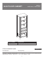
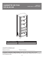
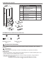
1549FC-24-201 24" White Finish Floor Cabinet
1549FC-24-242 24" Light Gray Finish Floor Cabinet
MODEL NUMBER DESCRIPTION
Español p. 13
MODEL #
1549FC-24-201; 1549FC-24-242
24-IN FLOOR CABINET

4
TABLE OF CONTENTS
Package Contents...........................................................................................................................5
Hardware Contents..........................................................................................................................5
Safety Instructions...........................................................................................................................5
Preparation ....................................................................................................................................6
Assembly or Installation Instructions .............................................................................................6
Care and Maintenance .................................................................................................................10
Warranty ......................................................................................................................................10
Replacement Parts List ................................................................................................................ 11

5
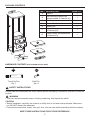
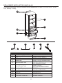
HARDWARE CONTENTS (NOT SHOWN ACTUAL SIZE)
PACKAGE CONTENTS
SAFETY INSTRUCTIONS
Please read and understand this entire manual before attempting to assemble, operate or install the
product.
WARNING
• There are several assembly steps, including unpacking, that require two adults.
CAUTION
•
Before installation, carefully use scissors or utility knife to cut and unwrap all parts. Make sure
you DO NOT discard the hardware.
• Follow these instructions closely, take your time, and use care while assembling this floor cabinet.
KEEP THESE INSTRUCTIONS FOR FUTURE REFERENCE.
PART DESCRIPTION QUANTITY
A Cabinet 1
B
Wall Mounting Spacer Bar
(preassembled to Cabinet (A))
1
C Shelf 2
D Drawer Divider 2
E Drawer box 1
F
Upper Drawer (preassembled
to Cabinet (A))
1
G
Lower Drawer (preassembled
to Cabinet (A))
1
AA
Touch Up Pen
Qty. 1
CC
Shelf Pin
Qty. 8
B
C
C
D
D
E
F
G
A

6
INSTALLATION INSTRUCTIONS
PREPARATION
Before beginning assembly of product, make sure all parts are present. Compare parts with
package contents list and hardware contents list. If any part is missing or damaged, do not attempt
to assemble the product.
Estimated Installation Time: 30 minutes.
Tools Required for Installation (not included): Phillips screwdriver, utility knife or scissors,
power drill with drill bit.
Helpful Tools (not included): Measuring tape, level
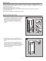
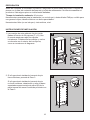
1. The handles for this floor cabinet are attached
to the inside of the drawers (F & G). Use the
attached string to open the drawers initially.
Unscrew the handles and reattach to the
outside of the drawers, as illustrated in the
diagram.
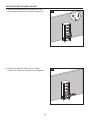
2. If the location you will be installing the floor
cabinet has baseboard molding, proceed to
Step 3.
If the location you will be installing the floor
cabinet does not have baseboard molding,
unscrew and remove the wall mounting spacer
bar (B) from the back of the cabinet before
proceeding to Step 3.
1
2
1
3
A
F
G
2
1
A
2
B

7
INSTALLATION INSTRUCTIONS
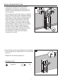
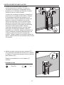
3. Clean area where the cabinet (A) will be
permanently located prior to beginning
installation, ensuring the cabinet (A) will not
interfere with any plumbing or electrical lines
once mounted.
Locate wall studs and mark locations. With the
help of another adult, place completed cabinet
assembly in its final location. Adjust the height
of the cabinet (A) by twisting the adjustable
leveler foot pins on the bottom of each leg.
Twist clockwise to decrease height or twist
counter-clockwise to increase cabinet height.
Using hardware appropriate for your wall type
such as cabinet screw or toggle bolt (not
included), secure cabinet (A) to preferably
two wall studs anywhere through the cabinet
mounting bar. Be careful not to disturb
any electrical or water lines that may be
concealed in the wall.
CC
4. Screw shelf pins (CC) hand tight into the threaded
holes of cabinet (A). Place shelf (C) on top of shelf
pins (CC).
Repeat for the remaining shelf (C).
Hardware Used
Shelf Pin
x 8
Baseboard
3
1
2
A
4
1
CC
2
C
C
A

8
INSTALLATION INSTRUCTIONS
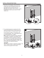
5. As shown in the diagram, fully extend the
drawer and locate the plastic levers on the
metal glide tracks. Push the left-side and
right-side levers at the same time to
disengage the drawer from the drawer glides.
Gently lift the drawer up to remove it from
cabinet (A).
6. To reinstall drawer(s) into cabinet (A), fully
extend metal glide tracks. Gently lower and
slide drawer box into rear glide catch. Next,
lower drawer box down to completely rest
on extended glides. Then, push plastic levers
to lock the drawer box in place.
Note: Drawer box alignment can be adjusted,
if necessary. As shown in the diagram, spin
the adjustment wheel to the left to raise the
drawer box, or to the right to lower the drawer
box. The left and right-side glide heights can
also be adjusted independently in order to find
the drawers best alignment position.
CAUTION
DO NOT force drawer or damage to glide(s) may
occur. If drawer does not slide in with ease,
remove and try again from the start.
5
2
1
A
6
1
2
3
A

9
INSTALLATION INSTRUCTIONS
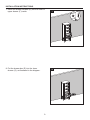
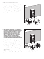
7. Insert two drawer dividers (D) into the notch of
upper drawer (F) inside.
8. Put the drawer box (E) into the lower
drawer (G), as illustrated in the diagram.
7
D
F
8
E
G

10
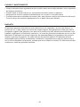
CARE AND MAINTENANCE
WARRANTY
• Dust the floor cabinet regularly with a soft, non-lint producing cloth or household dusting product.
• You can clean the floor cabinet with a gentle, non-abrasive household cleaner.
• Make sure to dry the wood immediately with a soft cloth or towel.
• Tips for using touch-up pen (AA): For scratches, stroke in direction of scratch. Rub off excess
colorant promptly with a soft cloth.
The manufacturer warrants this item against defects in materials and workmanship for a period of
one (1) year from the date of original retail purchase. This warranty applies only to the original
purchaser. This warranty does not apply to any damage on the product by accident, misuse, or
modified, improper installation or by affixing accessories not produced by the manufacturer. The
manufacturer is not accountable whatsoever for product installation during the warranty period.
There is no further expressed warranty. The manufacturer shall not be legally responsible for
incidental, consequential or special damages arising at or in connection with product use or
performance except as may otherwise be accorded by law. The manufacturer disclaims any and
all implied warranties.

11
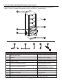
REPLACEMENT PARTS LIST FOR 1549FC-24-201
For replacement parts, call our customer service department at 1-855-571-1044, 9 a.m. - 5 p.m.,
EST, Monday - Friday.
PART DESCRIPTION PART #
B Wall Mounting Spacer Bar FC-WALL MOUNTING BAR-201
1549FC-24-201-SHELFC Shelf
1549FC-24-201-DRAWER BOX
1549FC-24-201-DIVIDERD Drawer Divider
E Drawer Box
1549FC-24-201-
TOP DRAWER FRONT
H Upper Drawer Front
1549FC-24-201-
BOTTOM DRAWER FRONT
I Lower Drawer Front
AA Touch-up Pen OF-0010
BB Handle-brushed nickel 1549-BN HARDWARE
CC Shelf Pin PU17-SP-002
DD Leveler T-1007
EE 14-IN Glide Track Set SH-ABC-14IN-3A
H
I
B
C
E
D
AA
BB
DD EE
CC

12
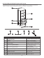
REPLACEMENT PARTS LIST FOR 1549FC-24-242
For replacement parts, call our customer service department at 1-855-571-1044, 9 a.m. - 5 p.m.,
EST, Monday - Friday.
PART DESCRIPTION PART #
B Wall Mounting Spacer Bar FC-WALL MOUNTING BAR-242
1549FC-24-242-SHELFC Shelf
1549FC-24-242-DRAWER BOX
1549FC-24-242-DIVIDERD Drawer Divider
E Drawer Box
1549FC-24-242-
TOP DRAWER FRONT
H Upper Drawer Front
1549FC-24-242-
BOTTOM DRAWER FRONT
I Lower Drawer Front
AA Touch-up Pen OF-0120R
BB Handle-brushed nickel 1549-BN HARDWARE
CC Shelf Pin PU17-SP-002
DD Leveler T-1007
EE 14-IN Glide Track Set SH-ABC-14IN-3A
H
I
B
C
E
D
AA
BB
DD EE
CC

13
1549FC-24-201 Armario de Pie de 24" con Acabado Blanco
1549FC-24-242 Armario de Pie de 24" con Acabado Gris Claro
NÚMERO DE MODELO DESCRIPCIÓN
MODELO #
1549FC-24-201; 1549FC-24-242
GABINETE DE PISO
DE 60,96 CM
ADJUNTE SU RECIBO AQUÍ
Número de serie__________________ Fecha de compra__________________
¿Preguntas, problemas, piezas faltantes? Antes de volver a la tienda, llame a nuestro
Departamento de Servicio al Cliente al 1-855-571-1044 de lunes a viernes de 9:00 a.m. a 5:00 p.m.,
hora estándar del Este.

14
ÍNDICE
Contenido del paquete..................................................................................................................15
Aditamentos........................................................................................................................15
Información de seguridad..............................................................................................................15
Preparación..................................................................................................................................16
Instrucciones de ensamblaje o instalación...................................................................................16
Cuidado y mantenimiento..............................................................................................................20
Garantía.........................................................................................................................................20
Lista de piezas de repuesto...........................................................................................................21

15
ADITAMENTOS (NO SE MUESTRAN EN TAMAÑO REAL)
CONTENIDO DEL PAQUETE
PIEZA DESCRIPCIÓN CANTIDAD
A Armario 1
B
Barra Espaciadora para
Montaje de Pared
(prearmada en el armario (A))
1
C Estante 2
D Separador de Cajones 2
E Caja del cajón 1
F
Cajón Superior (prearmada en
el armario (A))
1
G
Cajón Inferior (prearmada en
el armario (A))
1
AA
Aplicador de retoque
Cant. 1
CC
Pasador de repisa
Cant. 8
B
C
C
D
D
E
F
G
A
INFORMACIÓN DE SEGURIDAD
Lea y comprenda completamente este manual antes de intentar ensamblar, usar o instalar el
producto.
ADVERTENCIA
• Hay varios pasos de ensamblaje, incluido el desembalaje, que requieren dos adultos.
PRECAUCIÓN
•
Antes de la instalación, corte y desenvuelva todas las partes con cuidado usando tijeras o una
navaja. Asegúrese de NO DESECHAR el material.
•
Siga estas instrucciones detenidamente, tómese el tiempo necesario y tenga cuidado al
ensamblar este
armario de pie.
GUARDE ESTAS INSTRUCCIONES PARA REFERENCIA FUTURA.

16
1. Las manijas de este gabinete de piso están
fijadas al interior de los cajones (F y G). Use
la cuerda atada para abrir los cajones
inicialmente. Desatornille las manijas y vuelva
a colocarlas en el exterior de los cajones,
como se muestra en el diagrama.
2. Si el lugar donde instalará el armario de pie
tiene molduras, proceda al Paso 3.
Si el lugar donde instalará el armario de pie
no tiene molduras, desatornille y retire la barra
espaciadora para montaje de pared (B) de la
parte trasera del armario antes de proceder con
el Paso 3.
1
2
1
3
A
F
G
2
1
A
2
B
INSTRUCCIONES DE INSTALACIÓN
PREPARACIÓN
Antes de comenzar a ensamblar el producto, asegúrese de tener todas las piezas. Compare las
piezas con la lista del contenido del paquete y la lista de aditamentos. No intente ensamblar el
producto si falta alguna pieza o si estas están dañadas.
Tiempo de instalación estimado:
30 minutos.
Herramientas necesarias para la instalación (no se incluyen): destornillador Phillips, cuchillo para
uso general o tijera, taladro eléctrico con broca para taladro.
Herramientas útiles (no se incluyen): cinta métrica, nivel.

17
INSTRUCCIONES DE INSTALACIÓN
CC
4. Apriete a mano los soportes para estante (CC)
en los orificios roscados del armario (A). Coloque
el estante (C) en la parte superior de los soportes
para estante (CC).
Repita el procedimiento con la estante (C)
restante.
Hardware Used
Shelf Pin
x 8
Moldura
3
1
2
A
4
1
CC
2
C
C
A
3. Limpie la zona donde estará colocado
permanentemente el armario (A) antes de
comenzar la instalación, asegurando que el
armario (A) no interfiera con tuberías o cables
eléctricos una vez esté montado.
Localice los montantes de pared y marque sus
posiciones. Con ayuda de otro adulto, coloque
el ensamblaje terminado del armario en su
ubicación final. Ajuste la altura del armario (A)
girando los pernos niveladores en la parte
inferior de cada pata. Gire en sentido de las
agujas del reloj para bajar la altura o gírelas
en sentido contrario a las agujas del reloj para
aumentar la altura del armario. Usando
materiales apropiados para su tipo de pared,
tales como tornillos para armario o pernos
acodados (no incluidos), asegure el armario (A)
a dos montantes de pared preferiblemente, en
cualquier parte de la barra de montaje del
armario. Tenga cuidado de no dañar tuberías de
agua o cables eléctricos que puedan estar ocultos
en la pared.

18
INSTRUCCIONES DE INSTALACIÓN
5. Como se muestra en el diagrama, extienda
completamente la gaveta y ubique las
palancas de plástico en los rieles de
deslizamiento metálicos. Empuje las palancas
del lado izquierdo y del lado derecho al
mismo tiempo para desenganchar la gaveta
de los deslizadores para gaveta. Levante la
gaveta suavemente para retirarla del
armario (A).
5
2
1
A
6
1
2
3
A
6. Para reinstalar las gavetas en el armario (A),
extienda los rieles de deslizamiento metálicos
por completo. Baje con cuidado la gaveta y
deslícela hasta el cerrojo posterior de los
rieles deslizantes. A continuación, baje la
caja de la gaveta para que se asiente por
completo sobre los rieles deslizantes
extendidos. Luego, presione las palancas
de plástico para asegurar la caja de la gaveta
en su lugar.
Nota: la alineación de la caja de la gaveta se
puede ajustar, si es necesario. Como se
muestra en el diagrama, gire la rueda de
ajuste hacia la izquierda para levantar la caja
de la gaveta, o hacia la derecha para bajarla.
También se puede regular la altura de los
rieles de deslizamiento a la izquierda y a la
derecha independientemente para encontrar la
mejor posición de alineamiento de las gavetas.
PRECAUCIÓN
NO fuerce ni dañe la gaveta, ya que podrían producirse daños en los deslizadores. Si la
gaveta no se desliza con facilidad, retírela e intente nuevamente desde el principio.

19
INSTRUCCIONES DE INSTALACIÓN
7. Inserte dos separadores de cajones (D) en
las ranuras internas de los cajón superior (F).
8. Coloque la caja del cajón (E) en el cajón
inferior (G), como se muestra en el diagrama.
7
D
F
8
E
G

20
CUIDADO Y MANTENIMIENTO
GARANTÍA
• Limpie el armario de pie regularmente con un paño suave que no deje pelusas o con un producto
de limpieza doméstico.
• Puede limpiar el armario de pie con un limpiador doméstico suave no abrasivo.
• Asegúrese de secar la madera inmediatamente con un paño o una toalla suave.
• Consejos para usar el aplicador de retoque (AA): para rayones, aplique en la dirección del rayón.
Frote el exceso de colorante rápidamente con un paño suave para retirarlo.
El fabricante garantiza este artículo contra defectos en los materiales y la mano de obra por un
período de un (1) año a partir de la fecha de compra original. Esta garantía es válida solo para el
comprador original. Esta garantía no se aplica si el producto ha sido dañado por accidentes o uso
indebido, modificación o instalación incorrecta, o a causa de elementos accesorios que no son del
fabricante. El fabricante no asume ningún tipo de responsabilidad por la instalación del producto
durante el período de garantía. No existe otro tipo de garantía explícita. El fabricante no será
responsable legal por daños accidentales, resultantes o especiales que surjan en relación con el
uso o el funcionamiento del producto, excepto que la ley indique lo contrario. El fabricante rechaza
cualquiera y todas las garantías implícitas.

21
LISTA DE PIEZAS DE REPUESTO PARA 1549FC-24-201
Para obtener piezas de repuesto, llame a nuestro Departamento de Servicio al Cliente all
1-855-571-1044, de lunes a viernes de 9:00 a.m. a 5:00 p.m., hora del Este.
PIEZA DESCRIPCIÓN PIEZA #
B
Barra Espaciadora para
Montaje de Pared
FC-WALL MOUNTING BAR-201
1549FC-24-201-SHELF
C Estante
1549FC-24-201-DRAWER BOX
1549FC-24-201-DIVIDERD Separador de Cajones
E Caja del cajón
1549FC-24-201-
TOP DRAWER FRONT
H Frente de la gaveta superior
1549FC-24-201-
BOTTOM DRAWER FRONT
I Frente de la gaveta inferior
AA Aplicador de retoque OF-0010
BB Manilla-níquel cepillado 1549-BN HARDWARE
CC Pasador de repisa PU17-SP-002
DD Nivelador T-1007
EE Juego de Pistas de Deslizamiento de 14 PGDAS SH-ABC-14IN-3A
H
I
B
C
E
D
AA
BB
DD EE
CC

22
LISTA DE PIEZAS DE REPUESTO PARA 1549FC-24-242
Para obtener piezas de repuesto, llame a nuestro Departamento de Servicio al Cliente all
1-855-571-1044, de lunes a viernes de 9:00 a.m. a 5:00 p.m., hora del Este.
PIEZA DESCRIPCIÓN PIEZA #
B
Barra Espaciadora para
Montaje de Pared
FC-WALL MOUNTING BAR-242
1549FC-24-242-SHELF
C Estante
1549FC-24-242-DRAWER BOX
1549FC-24-242-DIVIDERD Separador de Cajones
E Caja del cajón
1549FC-24-242-
TOP DRAWER FRONT
H Frente de la gaveta superior
1549FC-24-242-
BOTTOM DRAWER FRONT
I Frente de la gaveta inferior
AA Aplicador de retoque OF-0120R
BB Manilla-níquel cepillado 1549-BN HARDWARE
CC Pasador de repisa PU17-SP-002
DD Nivelador T-1007
EE Juego de Pistas de Deslizamiento de 14 PGDAS SH-ABC-14IN-3A
H
I
B
C
E
D
AA
BB
DD EE
CC

WWW.EDBYELLEN.COM

-
 1
1
-
 2
2
-
 3
3
-
 4
4
-
 5
5
-
 6
6
-
 7
7
-
 8
8
-
 9
9
-
 10
10
-
 11
11
-
 12
12
-
 13
13
-
 14
14
-
 15
15
-
 16
16
-
 17
17
-
 18
18
-
 19
19
-
 20
20
-
 21
21
-
 22
22
-
 23
23
-
 24
24


ED Ellen DeGeneres 1549FC-24-242 Guía de instalación
- Tipo
- Guía de instalación
en otros idiomas
Otros documentos
-
 GreenTouch 1601WC-24-295 FLW Collection 1601 Wall Cabinet Cherry Manual de usuario
-
Scott Living 1192VA-36-245 Guía de instalación
-
allen+roth allen roth 60-in Vanity Guía de instalación
-
-
-
Allen + Roth 1605VA-36-201-925 Guía de instalación
-
-
-
VALEROSA 1658WC-24-267 24-in W x 28-in H x 10-in D Rustic Taupe Oak Bathroom Wall Cabinet Manual de usuario
-
