Jamara 053290 EP Dakar 24 GHz Instrucciones de operación
- Categoría
- Juguetes a control remoto
- Tipo
- Instrucciones de operación

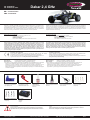
Dakar 2,4 GHz
No. 053290 EP
No. 053291 EP LiPo
09/22
Frequency bands: 2.4Ghz Frequency range: 2405,5 MHz - 2475,0 MHz EIRP: 49,09 mW (max. power transmitted
ES - Instrucciones
GB - Instruction
Declaración de conformidad
Por la presente JAMARA e.K. declara que los productos „Dakar 2,4 GHz, No. 053290,
No. 053291“ cumple con la Directiva 2014/35/UE, 2014/53/UE y 2011/65/UE.
El texto completo de la declaración de conformidad de la UE está disponible en la
siguiente dirección de Internet: www.jamara-shop.com/Conformity
Certicate of Conformity
Hereby JAMARA e.K. declares that the products „Dakar 2,4 GHz, No. 053290 and No.
053291“ comply with Directives 2014/35/EU, 2014/53/EU and 2011/65/EU.
The full text of the EU Declaration of Conformity is available at the following Internet address:
www.jamara-shop.com/Conformity
ES - Información general
Jamara K. no se hace responsable de los daños causados al producto en sí o por medio de esto,
a menos que esto se debe al mal funcionamiento o errores de manejo. El cliente solo tiene la re-
sponsabilidad completa para el uso y manejo adecuado, incluyendo, sin limitaciones, el montaje,
el proceso de carga, el uso de hasta la elección de la zona de aplicación. Por favor, consulte las
instrucciones de uso y funcionamiento, contiene información y avisos importantes.
GB - General information
Jamara e.K. is not liable for any damage caused to the product itself or through this, provided this
is due to improper operation or handling errors. The Customer alone bears the full responsibility for
the proper use and handling, including without limitation, the assembly, the charging process, the
use and choice of the operation area. Please refer to the operating and user instructions, it contains
important information and warnings.
Este producto es un artículo de modelismo. Esto signica que el vehículo debe ser revisado
siempre (comprobar si hay daños, comprobar las uniones atornilladas, limpiar, etc...). Las
piezas de desgaste como el engranaje principal, el piñón del motor, rotula de conexión etc.
se desgastarán con el paso del tiempo y, por lo tanto, deben sustituirse. Las colisiones no
siempre se pueden evitar, por lo que los daños por colisión también se deben reparar o
reemplazar. Las piezas de desgaste o las piezas defectuosas debidas a colisiones o a un
mantenimiento insuciente no están cubiertas por la garantía, los costes y las reparaciones
correrán a cargo del propio comprador.
This product is a model building article. This means that the vehicle must always be serviced
(check for damage, check screw connections, clean etc...). Wear parts such as the main
gear, motor pinion, bone socket, etc. will wear out over time and must therefore be replaced.
Crashes cannot always be avoided, so crash damage must also be repaired or replaced.
Wear parts or defective parts due to crashes or insucient maintenance are not covered by
warranty, costs and repairs must be covered by the buyer himself.
jAtención!
Antes del uso: Encender primero el modelo, y después la emisora.
Después del uso: Apagar primero el modelo, y después la emisora.
● No utilizar su modelo fuera de la distancias de visibilidad. Tanto la visibilidad como la capacidad
máxima de su modelo depende de muchos factores, tales como el tiempo, frecuencia de
interferencia y el lugar de utilización. Realice una prueba antes de cada uso del modelo con una
segunda persona que ja el modelo. Con este procedimiento se puede comprobar cómo el
modelo reacciona durante la pérdida de señal causada por ejemplo por una batería descargada
o la emisora apagada.
Attention!
Before operating: Switch the transmitter on rst then the model.
When nished: First switch o the model then the transmitter.
● Never operate your model beyond sight. Both the maximum visibility as well as the max.
range of your model will depend on many factors such as weather, location and
interfering frequencies. Therefore, before each use perform a range test with a second
person securely holding the model and also check how the model reacts if there is a
signal failure e.g. when empty transmitter batteries are installed.
Este modelo no es un juguete!
Atención: Mantenga necesariamente lejosde los niños.
Contiene piezas pequeñas.
RIESGO DE ASFIXIA!
No es recomendable para los niños menores de 36 meses.
This model is not a toy!
Warning: Keep away necessarily from children.
Contains small parts which can be swallowed.
RISK OF SUFFOCATION!
Not suitable for children under 36 months.
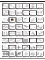
Herramientas recomendados Recommended Tool
No. 190065
Convergencia medidasCam-
ber adjusting Tool
No. 232060
Cinta adhesiva 2 caras
Doublesided power tape
No. 230409 20 g
„Wheel blood“
Cola de neumatico
Rim Glue
No. 232423 medium
Adhesivo bloqueo de tuerca
Nut lock
No. 281730
Tijeras espacial para lexan
Lexan scissors
No. 059273 1:10
Clip de carroceria
Body clips
No. 505401 pequeña/small
Clip de carroceria
Body clips
No. 153059
X-Peak 80 V2
Cargador
Charger
Lea atentamente la instruccion completa y seguridad antes de poner el modelo
en funcionamiento.
Atención! Leer completamente las notas de advertencia / instrucciones de
seguridad estos son para su seguridad y puede evitar accidentes / lesiones.
Read the complete instructions and security instructions carefully before using the
model.
Caution! Please fully and carefully read warnings/ safety instructions. These are
for our own security and can avoid accidents/injuries.

2
1
2
5
4
3
1 2 3
4
6
NiMh
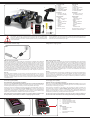
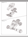
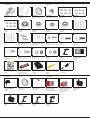
Contenido del kit:
1. Modelo
2. Emisora
3. Batería LiPo (053291)
4. Cargador LiPo
5. Batería NiMh (053290)
6. Cargador USB NiMh
Accesorios:
• Emisora: 4 x AA 1,5V,
No. 140267 (4 piezas)
Datos técnicos:
• Medidas:
~ 500 x 280 x 210 mm
• Peso: 2170 g
• Batería:
NiMh 7,2 V 2000 mAh
(053290)
LiPo 7,4 V 5000mAh
(053291)
• Motore:
Venti 550, 270 W
Salvo error y omisión.
.
Box contents
1. Model
2. Transmitter
3. Battery LiPo (053291)
4. Charger LiPo
5. Battery NiMh (053290)
6. USB-Charger NiMh
Accessories:
• Transmitter: 4 x AA 1,5V,
No. 14 0267 (4 pieces)
Technical data:
• Dimensions:
~ 500 x 280 x 210 mm
• Weight: 2170 g
• Battery:
NiMh 7,2 V 2000 mAh
(053290)
LiPo 7,4 V 5000mAh
(053291)
• Motor:
Venti 550, 270 W
No responsibility is taken for the
correctness of this information.
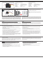
Primeros pasos - Proceso de carga Getting Started - Charging process
NiMh Proceso de carga (053290)
Conecta el cargador USB a un puerto USB. Aquí recomendamos un adaptador de red USB (2A)
para la toma de corriente. Las conexiones USB de los ordenadores y portátiles no suelen proporci-
onar suciente corriente para cargar la batería. El LED del cargador se ilumina en verde. Conecte el
cargador USB a la batería de NiMh. El LED rojo del cargador USB señala el proceso de carga. Si el
enchufe del cargador y el enchufe de la batería de la unidad no coinciden, se incluye un adaptador
de carga con su modelo. Cuando la batería está completamente cargada, el LED se ilumina en
verde. Asegúrese de que no se sobrepasa el tiempo de carga. No cargue ninguna otra batería que
no sea la de NiMh suministrada. El tiempo medio de carga de la batería NiMh vacía suministrada
es de aproximadamente 6 a 8 horas. Si el LED parpadea, hay un fallo. Póngase en contacto con el
servicio de atención al cliente.
Atención:
Sólo cargue baterías adecuadas con este cargador. Las baterías adecuadas son las de níquel-
hidruro metálico con un máximo de 6 celdas, una tensión nominal máxima de 7,2 V y un máximo de
2000 mAh. La batería debe tener un conector Tamiya. Cargar baterías inadecuadas puede dañar
el cargador y la batería. ¡Peligro de incendio! La conexión de carga del cargador no debe soldarse
ni modicarse nunca.
NiMh Charging process (053290)
Connect the USB charger to a USB port. We recommend a USB adapter (2A) for the grounding
receptable. USB ports of computers and laptops usually cannot provide sucient current to charge
the battery. The LED on the charger lights up green. Connect the USB charger to the NiMh drive
battery. The red LED of the USB charger signals the charging process. If the plug of the charger and
the plug of the drive battery do not match, a charging adapter is included with your model. When the
battery is fully charged, the LED lights up green. Make absolutely sure that the charging time is not
exceeded. Do not charge any batteries other than the NiMh battery supplied. The average charging
time for the empty NiMh battery supplied is approx. 6 - 8 hours. If the LED ashes, there is a fault.
Please contact the customer service.
Caution:
Only charge suitable battery‘s with this charger. Suitable battery‘s are Nickel metal hydride battery‘s
with max. 6 cells, max. 7,2 V nominal voltage and max. 2000mAh. The battery must have a tamiya
plug. The charging of unsuitable battery‘s can cause damage to the charger and the battery‘s.
Fire Hazard! The charging connection of the charger is not allowed to get altered or soldered to a
dierent balancer plug type!
Ha comprado un modelo RTR. Es decir, el vehículo está en gran medida listo para su
uso inmediato. Sin embrago, es esencial revisar el modelo para vericar posibles daños
mecánicos o defectos o fallas eléctricas antes y después de cada uso. También se debe
comprobar la libertad de movimiento de todas las piezas móviles y la estanqueidad de las
uniones antornilladas.
You have purchased a RTR model, which means it should be ready for immediate use after
charging all batteries. You need to check the car, electronics and all plastic parts after each
use to make sure no parts are damaged. Also all the moving parts must be checked for their
clearance, bolts and screws that they are tight.
Proceso de carga LiPo (053291)
Notas importantes sobre la idoneidad de la batería:
Asegúrese de que sólo utiliza baterías de polímero de litio con el conector del equilibrador XH.
Sólo estas pueden utilizarse con el cargador. No se pueden utilizar otras conexiones ni otros tipos
de baterías (puede haber peligro de incendio por inversión de polaridad o sobrecarga).
Póngase en contacto con el fabricante de su batería para saber si ésta es adecuada. Utilice única-
mente baterías LiPo con una capacidad de al menos 1600mAh (de lo contrario, existe el riesgo de
incendio debido a una corriente de carga excesiva). Si utiliza baterías con una capacidad inferior
a 1600mAh, las baterías deben estar aprobadas para una corriente de carga de 1600mA (carga
rápida). Pregunte al fabricante de su batería si ésta cumple estos requisitos.
Sólo puede conectar una sola batería al cargador a la vez. Cargar 2 baterías al mismo tiempo
NO está permitido y causará daños a la batería o al cargador (peligro de incendio).
LiPo Charging process (053291)
Important notes on the suitability of the battery:
Make sure to use only lithium polymer batteries with XH balancer connector. Only these may
be used with the charger. Other connections and battery types must not be used (re hazard due to
reverse polarity or overcharging may result).
Please contact the manufacturer of your battery to nd out whether your battery is suitable. Only
LiPo batteries with a capacity of at least 1600mAh must be used (otherwise there is a risk of
re due to excessive charging current). If you use batteries with a capacity below 1600mAh, the
batteries must be approved for a charging current of 1600mA (Speedcharging). Please ask the
manufacturer of your battery if your battery meets these requirements.
You may only connect one single battery to the charger at a time. Charging 2 batteries at
the same time is NOT allowed and will cause damage to the battery or charger (re hazard).
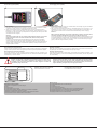
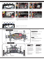
IT
1. Entrada 100 - 240 V
2. Conectors equilibrado 2 células
3. Conectors equilibrado 3 células
(No es necesario en este modelo)
4. LEDs de estado
GB
Technical data:
1. Power Slot 100 - 240 V
2. 2S Balancer
3. 3S Balancer
(Not required for this model)
4. Status LEDs
Solo para / Only for:
Version 053291
Solo para:/Only for:
Version 053290

4x AA
1 2
¡Atención!
Después de cada carga es importante de: Desconectar siempre la batería del car-
gador y el cargador de la fuente de alimentación. Si después de la carga se deja
conectado a uno o otra puede causar daños a la batería, cargador o a la fuente de
alimentación (peligro de incendio).
Danger!
Always disconnect the battery from the charger immediately after charging. Always
disconnect the charger from the power supply immediately after disconnecting the
battery. Inserting the rechargeable battery or charger after charging will result in da-
mage to the battery, charger or the power supply (re hazard).
Cargar una batería
1. Enchufa el cable de alimentación del cargador en una toma de corriente adecuada. Los LEDs
se iluminan en verde e indican que el cargador está listo para la carga.
2. Ahora conecta la batería vacía al cargador. Baterías de 7,4V 2S al conector de 3 polos o
baterías de 11,1V 3S al conector de 4 polos. No hagas fuerzae y presta atención de no invertir
la polaridad. Los LEDs se volverán rojos después de unos segundos para indicar que las celdas
de la batería se están cargando.
Atención!
Al conectar una batería 2S, sólo los 2 primeros LEDs (Celda1-2) cambian a rojo, el LED 3
(Celda 3) permanece verde. Al conectar una batería 3S, todos los LEDs (Celda1-3)
cambian a rojo.
En cuanto una célula de la batería está completamente cargada, el LED correspondiente
cambia a verde. Como las celdas se cargan individualmente, es posible que una celda se
cargue completamente antes que las demás. Deje siempre la batería en el cargador hasta que
todas las celdas conectadas estén completamente cargadas (en verde) para permitir que el
cargador equilibre su batería.
Charging a battery
1. Plug the power cord of the charger into a suitable socket. The LEDS light up green and indicate
that the charger is ready for charging.
2. Now connect the empty battery to the charger. 7.4V 2S batteries to the 3 pin connector or 11.1V
3S batteries to the 4 pin connector. Do not use force and pay attention to reverse polarity. The
LEDs change to red after a few seconds and indicate that the battery cells are charging.
Attention:
When connecting a 2S battery, only the rst 2 LEDs (Cell1-2) change to red, LED 3 (Cell 3)
will remain green. When 3S batteries are connected, all LEDs are red (Cell1-3).
As soon as a the battery cell is full, the corresponding LED changes to green. Because the cells
are charged individually in a balanced way, it is possible that one cell is fully charged earlier than
the others. Always leave the battery on the charger until all connected cells are fully charged
(green) to allow the charger to balance your battery
Proceso de carga LiPo (053291) LiPo Charging process (053291)
Reconocimiento de una batería llena.
Cuando conectes una batería llena al cargador, los LEDs se pondrán rojos durante unos segundos
y luego volverán a ponerse verdes. Esto signica que la batería ya está completamente cargada.
Reconocimiento de una batería defectuosa.
Si los LEDs permanecen en verde cuando se conecta una batería vacía, hay un defecto en la
batería (defecto en la celda o descarga profunda). En este caso, desconecte la batería del cargador
inmediatamente y utilice otra batería.
Detecting a full battery.
When you connect a full battery to the charger, the LEDs will turn red for a few seconds and then
turn green again. This means that the battery is already fully charged.
Detecting a defective battery.
If the LEDs remain green when an empty battery is connected, there is a defect in the battery (cell
defect or deep discharge). In this case, immediately disconnect the battery from the charger and
use another battery.
Instalación de las pilas en el transmisor
Inserte 4 baterías AA en la emisora.
Inserting batteries into the transmitter
Put 4 AA Batteries into the Transmitter
Advertencia sobre las baterías:
Las baterías no recargables no se pueden cargar!
No abrir!
No arrojar al fuego!
No mezcle baterías nueva y viejas!
No mezcle baterías alcalinas, estándar (carbono-zinc) o baterías recargables!
Las baterías recargables deben retirarse del juguete!
Las baterías recargables sólo pueden cargarse bajo la supervisión de un adulto!
Los conectores de conexión no deben estar en cortocircuito!n!
Battery warning:
Non-rechargeable batteries are not to be recharged!
Do not open!
Do not dispose of in re!
Do not mix old and new batteries!
Do not mix alkaline batteries, standard (carbon-zinc) or rechargeable batteries!
Rechargeable batteries are to be removed from the toy before being charged!
Rechargeable batteries are only to be charged under adult supervision!
The supply terminals are not to be short-circuited!

4
1
505080
505081
07 9996
505079
505080
505081
079996
505079
ON/OFF
● Ahora ponga la batería en la porta baterías en el vehículo. Asegúrese de que el porta
baterías está asegurado correctamente con los 2 seguros para el porta baterías ncluidos.
● Conecte ahora la batería con el regulador del modelo. Si el enchufe del regulador y el echufe
de la batería no coinciden, se incluye un cable adaptador con su modelo.
● Encender la emisora y cerciórese de todos los botones del transmisor están en posición
neutral. Lea el capítulo para el uso del transmisor y sus controles cuidadosamente.
● Mantenga el carro en el aire en caso de que el controlador (ESC) del motor se encienda a su
máxima potencia.
● Encienda el control de la velocidad en el interruptor Encendido / Apagado (On / OFF).
● Le sugerimos que active ahora la unidad receptora a Prueba de Fallas en el armado.
Cuando se suministra, está desactivado.
● Si éste es su primer carro rc, le recomendamos conducirlo en una pequeña pista de prueba
para familiarizarse con el control del vehículo y los controles del transmisor.
● Put the battery into the battery holder in the vehicle. Make sure that the battery holder is scured
properly with the 2 included clips for the battery holder.
● Now connect the battery to the speed control in the model. If the plug of the speed control and
battery do not match, then you will nd a connection lead in your box
● Turn the radio on and make sure all the trim buttons on the transmitter are in neutral position.
Read the chapter for usage of the transmitter.
● Keep the car in the air in case that the motor turns at full power.
● Switch the speed control on the On / O switch.
● We encourage you now to activate your receiver‘s built-in Failsafe unit.
On delivery it is turned o. (see chapter Fail Safe).
● If this is your rst rc car, we recommend to drive it on a small test track to familiarise yourself
with the control of the vehicle and the controls of the transmitter.
¡Atencion!
Su vehículo tiene un pivote de suspensión delantera. Esto tiene
numerosas ventajas. Es muy resistente y es de fácil manteni-
miento. La conguración (setup) del carro ha sido diseñada para
que el eje motriz no se proyecte hacia afuera. Como con cual-
quier modelo, los tornillos y los pernos se pueden perder durante
una interrupción del carro. Esto puede resultar en una tolerancia
del eje motriz. El eje motriz puede entonces proyectarse hacia
afuera si se ejerciera presión alta. El tornillo interno de la bola
(No. del artículo.: 505081) le permitirá ajustar la tolerancia dando
por resultado los ajustes nos del ancho de la rodada. Para me-
jores resultados al colocar la bola del pivote por primera vez, por
favor ajuste siempre el pivote superior y más bajo de la misma
forma. Apriete tanto como el pivote lo permita y que se pueda
levantar y bajar fácilmente pero no tanto que lo proyecte fuera si
usted le da un ángulo completo a la dirección. El tornillo del en-
chufe de plástico (No. del artículo.: 505080) se utiliza solamente
para asegurar el nudillo de la dirección. Éste no debe ser dema-
siado apretado, de lo contario la dirección no queda suave y su
manejo puede ser afectado negativamente.
Attention!
Your vehicle has a pivot front suspension. This has a number of
advantages. It is very robust and easy to maintain. The set-up of
the car has been done so the drive shaft will not pop out. As with
any model, screws and bolts can losen during break-in of the
car. This can result in tolerance of the drive shaft. The drive shaft
can then pop out if high pressure is applied. The inner ball screw
(item No.: 505081) will enable you to adjust the tolerance resul-
ting in ne adjustments of the track width. For best results when
setting up the pivot ball for the rst time, please always adjust
the upper and lower pivot in the same way. Fasten as far as the
pivot can still be pulled up and down easyly but not as far that it
will pop out if you give full steering angle. The outer plastic socket
screw (item No.: 505080) is only used for securing of the steering
knuckle. This should not be too tight, otherwise the steering is
not smooth and the handling can be adversely aected.
Atención!
La junta homocinética delantero y trasero absorbe la mayor par-
te de la energía del motor y lo pasa al eje delantero y trasero.
Por lo tanto, los tornillos de cabeza hexagonal que mantienen la
junta homociética en el eje de salida de transmisión antes del
primero uso y en intervalos regulares (5-7 insertos) se debe
controlar y se es necesarios apretar. En la junta homocinética
delantera y trasera se debe insertar un anillo de goma. Controlar
el juego del árbol motor. El margen de juego debe ser aprox.
1-2 mm. Es necesario mover la junta homocinética para adaptar
el juego. Aquí tienen que aojar los tornillos sin cabeza con un
destornillador y ajustar la junta homocinética. A continuación, tor-
nillar los tornillos sin cabeza. De lo contrario la junta ho ocinética
se mueve en el eje de salida de transmisión y la homocinética
y el eje central se pueden dañar.
Attention!
The front and rear bone pan absorbs most of the motor‘s energy
and directs it to the front and rear axles. Therefore, the hexagon
socket screws which hold the bone pans on the transmission
output shafts must be checked and, if necessary, tightened be-
fore the rst use and in regular intervals e.g 5-7 uses. Insert
a rubber ring to the front and the back connection cup. Please
check the tolerance of the drive shaft. The tolerance should be
approx. 1 – 2mm. You may have to move the connection cups
to adapt the tolerance. Therefore you need to loosen the grub
screws to adapt the connection cup. Afterwards tighten the grub
screws. If not, the connection cups will move on the gear output
shaft. That might cause the connection cup and the middle drive
shaft to get damaged.
¡Atención!
Si su modelo tiene un interruptor On/O es importante apagar el modelo directamente
después de cada uso. Si el modelo tiene una batería extraible o un conector en la batería,
se debe desconectar inmediatamente después de cada uso del modelo. Si se deja encendi-
da la batería o conectada, la batería se puede descargar. Una vez que está descargada la
batería pierde la potencía o se puede dañar grave. En este caso la batería ya no puede ser
cargada o descargada y hay un peligro de in amación (peligro de incendio). Nunca intentar
de cargar o descargar baterías descargadas profundamente. El voltaje de la batería nunca
debe estar bajo 6 Voltios y la batería de NiMh nunca bajo 4 voltios para evitar descargas
profundas. La batería completamente cargada tiene una tensión de aproximadamente 8,4
Voltios y la batería NiMH de 8,5 voltios. Después de su uso, la batería intacta se debe car-
gar inmediatamente completamente, después de una fase de enfriamiento de al menos 10
minutos pero a más tardar después de 12 horas, para evitar una descarga profunda a través
del auto-descarga. Si la batería no se utiliza o se pone en el almacenamiento es necesario
comprobar o recargar la batería cada 3 meses, tensión (Para LiPo min. 8 voltios, para NiMh
min. 7,4 voltios). En caso de daños a la batería de disponer correctamente.
Danger.
Always switch o the model immediately after each use. Immediately after each use the
battery should be disconnected from the model. The battery can be deeply discharged by
leaving it switched on accidentally or leaving it plugged in. Deep discharge causes the bat-
tery to lose power or can be damaged to such an extent that charging or discharging is no
longer possible or the battery can self-ignite during charging or discharging (re hazard).
Never attempt to charge or discharge deep-discharge batteries. The voltage of the LiPo
batteries should never be under 6 volt to avoid a depth discharge. The fully charged LiPo
battery has a voltage of approx. 8,4 Volt. After usage, the intact battery has to be fully
charged after a cooling phase of at least 10 min but not longer than 12 hrs. This is to avoid
a deep discharge caused by a selfdischarge. When not using or storing the battery´s it has
to be checked at least every three months for voltage (8 Volt) or damage and if necessary
charged or disposed.
Batería /
Battery
Regulador
ESC
ON/OFF
Version EP Version EP LiPo
Regulador
ESC
Batería
Battery
Conexiones de regulador/batería
Battery connector

5
C
A
B
D
E
G
H
F
I
6
12
3
4
5
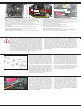
Cómo instalar la función a prueba de fallas
1. Instrucciones de la función
La función de la protección de pérdida de control es principalmente para los barcos y carros
r/c y los resguarda de algún daño a través del canal del acelerador. Cuando el receptor está
fuera de la señal de control, el receptor del acelerador volverá a regresar automáticamente a
la posición inicial que se instaló antes de comenzar para evitar la acción de error:
2. Cómo establecer la función
a. Encienda la energía del transmisor y entre a la condición de trabajo.
b. Conecte el receptor a la energía y entre a la condición de trabajo, la luz de la señal en
receptor estará parpadeando en todo momento.
c. Controle el acelerador del transmisor y mantenga el servo o el controlador ESC en
posición neutral.
d. Presione el botón de ajuste, el LED va a parpadear por 3 segundos (Véase en la gura de
la izquierda).
e. Suelte el botón de ajuste. Termina el ajuste
3. Prueba
a. Encienda el transmisor y entre a la condición de trabajo.
b. Haga contacto del receptor con la energía e inicie la condición de trabajo
c. Apague la energía del transmisor.
d. El acelerador del servo se instalará automáticamente.
e. Al terminar con los pasos arriba mencionados signicará que la instalación esta correcta.
How to setup the fail safe function
1. The instruction of function
The function of protection of losing control is mainly for r/c boats and cars and keeps them
away from damage through throttle channel. When the receiver is out of control signal, the
receiver of throttle will automatically return to the initial position which set up before starting to
avoid the error action :
2. How to set the function
a. Switch on the transmitter power and enter into the working condition
b. Connect the receiver with power and enter into the working condition, the signal light
on receivewill blink all the time.
c. Control the throttle of transmitter and keeps the servo or ESC in the neutral position.
d. Press the setting button, the LED will be ash for 3 seconds (see on pict. left).
e. Release the setting button. The setting is nished.
3. Testing
a. Switch on the transmitter and enter the working condition.
b. Contact the receiver with power and enter the working condition.
c. Turn o the power of transmitter.
d. The throttle of servo will be set automatically.
e. Finish these steps above means the setting is ok.
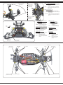
Componentes
1. Programación remota
2. Volante
3. Pedal Pulso
4. Compartimiento de las baterías
5. Canal de recarga
6. Canal que desee intro ducir el cable
simulador.
Si se carga en la toma de carga, por favor, abra
la tapa del compartimento de la batería. Esto se
utiliza para el enfriamiento.
Campo de programación
A. Invertir la dirección
B. Encendido / aleación
C. Trim de la Dirección
D. Enciende y apaga
E. Inversa de gas
F. Compruebe la alimen tación
G. Botón de encendido
H. Dual Rate
I. Gas
Trim
Si las ruedas no apuntan hacia adelante aún y
cuando el volante de la transmisión está en
neutral, usted puede ajustarlo con el botón del
ajuste la transmisión.
Trimm L/R = derecha/izquierda
Si las ruedas rotan hacia adelante o hacia atrás,
aún y cuando no se les haya indicado a través
de la transmisión, entonces también el acelera-
dor se necesita ajustar en la transmisión.
Trimm V/R = adelante/atrás
Colocar pilas a la emisora
• Retire la tapa del compartimiento de la
batería.
• Coloque 4 x AA pilas, respetando la
polaridad.
• Reemplace la tapa del compartimiento de
la batería.
Controls
1. Programming Box
2. Steering Wheel
3. Throttle Lever
4. Battery Hatch
5. Charge Socket
6. Simulator Cable Socket
If charging the batteries via the charging socket,
the battery hatch cover should be removed to
ensure sucient cooling.
Programming Panel
A. Steering Reverse (changed)
B. Power LED
C. Steering Trim
D. ON/OFF Switch
E. Throttle Reverse (changed)
F. Power Check
G. Binding Button
H. Dual-Rate (maximum steering deection)
I. Throttle Trim
Trim
If the wheels do not point straight forward even
though the steering wheel on the transmitter is
in neutral, you can adjust it with the trim button
on the transmitter.
Trim L/R = steering
Should the wheels rotate forward or backward,
even though no command was given through
the transmitter, then also the throttle needs to
be trimmed on the transmitter.
Trim V/R = forward/backward
Insert the batteries
• Remove the battery compartment cover.
• Fit the 4 x AA batteries, observe the correct
polarity.
• Replace the battery hatch
Para encender el transmisor y el receptor
Es imperativo que el emisor y el receptor estén unidos en el
modelo. La emisora sólo aceptará la señal su estación.
Si por alguna razón usted tiene que repetir la nueva conexión,
haga los siguientes pasos:
1. Coloque la batería cargada en la modelo. Ahora conecta la
batería de la unidad al controlador del modelo.
2. Coloque el cable de conexión de los tres canales.
3. Encender la receptor. El binding es siempre lo mismo en
todas las versiones. La LED en el receptor impieza a
parpadear y indica que el receptor no esta en el modo
binding.
4. Pulse el botón de encendido de la estación y, al mismo
tiempo cambiar el canal.
5. La emisora impieza a parpadear y indica que estas en el
modo binding.
6. Quitar el dedo el botón de encendido de la emisora y retirar
del enchufe del receptor.
7. Interruptor del transmisor. Y retire el cable de unión. El
sistema estará vinculado en el próximo inicio.
8. Si no hay éxito en el procedimiento, vuelva hacerlo todo
otra vez.
Recomendamos activar la unidad a prueba de fallas integrada
en su receptor. Está desactivado en el estado de entrega.
Brenda la antena de 2.4 GHz perpendicular, como en la foto
grafía en el lado. Mas no debe mantenerlo en la parte metálica,
debido a de extensión.
Binding the receiver to the transmitter
In the delivery state, the transmitter is already bound to the re-
ceiver. If the model does not respond to the transmitter, try bind-
ing it again.
For this purpose, proceed as follows:
1. Put the battery into the model.
Now connect the battery to the speed control in the model.
2. Plug the binding plug (included) into the channel 3 socket
on the receiver.
3. Switch the receiver system on. Depending on your soft-
ware version of your receiver indicates the dierent
binding mode (instead of ashing lights for example
LED or remains out completely). The binding process as
such is in all versions. The receiver LED will begin to ash
indicating that the receiver is in bonding mode.
4. Press and hold down the binding button on the transmitter
whilst switching it on.
5. The transmitter will begin to ash indicating that the recei-
ver is in bonding mode.
6. Release the binding button on the transmitter and turn o
the controller. Release the binding plug from the receiver.
7. Switch of the transmitter. And remove the binding wire. The
system be bound at the next start .
8. If the receiver fails to bond or does not function after bond-
ing repeat the above procedure until a successful bonding
is achieved.
We encourage you now to activate your receiver‘s built-in
Failsafe unit. On delivery it is turned o.
Mount the 2.4 GHz antenna vertically as shown in the diagram.
Do not allow any metal object to come into contact with the an-
tenna or to shield it as this will reduce the range.
Emisora 2,4 GHz 2CH Transmitter 2,4 GHz 2CH
2,4 GHz
Antena
Antenna
Receptor/Receiver
Testado de conexión
Binding Plug
Fail Safe
Setup LED

6
Controlador (instalada) Version EP
Datos tecnicos:
Voltaje 7,2 - 7,4 V
Batería 2 Lipo | 6 NiCd/NiMh células
Resistencia inerna Fwd: 0.002 Ohm, Bwd: 0.004 Ohm
BEC-Voltaje BEC 2A/5V (Linear mode BEC)
Aplicaión RC-Car 1:10
Protección Baja tensi´´on de bloque
Carga continua 40 A
Tamaño ~ 45 x 32 x 26 mm
Controller (installed) Version EP
Technical Data:
Operating Voltage 7,2 - 7,4 V
Battery Pack 2 Lipo | 6 NiCd/NiMh Cells
Internal Resistance Fwd: 0.002 Ohm, Bwd: 0.004 Ohm
BEC Voltage BEC 2A/5V (Linear mode BEC)
Intended use RC-Car 1:10
Protection Circuit Under voltage cut o
Continuous load 40 A
Size ~ 45 x 32 x 26 mm
Si está utilizando una batería Lipo, debe activar el Lipomodo a través del Jumper (puente de
connexión). Antes de llegar a su minima tension,se va a apagar el regulador. Solo asi la bat-
ería lipo está protegido contra descargas o los daños causados por una descarga profunda!
En el umbral de 6 V de tensión total, el regulador se apaga para no descargar la batería. Si
está utilizando una batería NiMh tienes que poner el Jumper en posicion NiMH. El regulador
no se apaga en 6 V de tensión total pero permite una descarga de unos aprox. 4 voltaje total.
This regulator has two battery modes which will be set with jumpers. If you are using a Lipo
battery this jumper has to be set to Lipo. This function protects the lipo battery against deep
discharge and possible damage due to deep discharge! At a threshold voltage of 6 V total
the esc switches autom. o to safe the battery from under voltage. If you are using a NiMH
battery this jumper has to be set to NiMh. The controller allows a voltage less than 6 V down
to 4 V.
¡Atención!
El modelo está protegido contra salpicaduras de agua, pero no es impermeable.
Evitar charcos que pueden tener contacto con el regulador montado en el vehículo. No sumerja
el regulador bajo el agua. Después de cada giro en mojado, el completo regulador se debe estar
completamente seco. Daños y accidente causado por un uso inadecuado o falta de mantenimiento
no está cubierto por la garantía.
WARNING
Your controller is Splash-proof. Not waterproof.
Avoid puddles that are higher than the controller is installed in the vehicle. Do not get the model un-
der water. After each ride in the wet, the complete controller must be thoroughly dried and lubricate
the mechanical components. Damage caused by improper use overload or lack of maintenance is
not covered under warranty.
ES
Si desea desactivar la marcha atrás del regulador, debe congu-
rar el puente para deshabilitarlo. Si el puente está congurado
para habilitar, se activa la marcha atrás.
GB
If you want to disable the backward function just set the jumper to
disable. If the jumper is set to enable the backward function is
enabled.
Conguración del Regulador
El regulador se calibra automáticamente con la señal de la emisora. Para esto el trim (ajuste no)
del acelerador de la emisora tiene que estar en posición neutral. Encienda primero la emisora y
después el regulador. El regulador conrma la calibración automática con una melodía corta y
después se encuentra listo para funcionar. Si el regulador no reconoce una señal clara o si el trim
del acelerador no esta en posición neutral, el regulador no se iniciará.
Conguring your controller
The speed controller automatically calibrates itself to the transmitter signal. For this, the trim button
of the gas channel at the transmitter is in the middle. Turn on the transmitter and then the speed
controller. The speed controller signals the calibration with a short melody and is ready for use.
In case the speed controller has no clear signal or the trim control is not set to neutral, the speed
controller will not initialize.
Uso del Regulador
Para el uso del regulador, siga los siguientes pasos:
• Encienda la emisora y asegúrese de que el recorrido del canal del gas (acelerador) está
programado exactamente para un re corrido del +/- 100%.
• Conecte la batería, con el interruptor del receptor todavía apagado, asegurándose de la
polaridad correcta.
• Encienda el interruptor del receptor.
• Con la batería conectada, el regulador esta “vivo”, así que hay que tener mucho cuidado para
evitar posibles lesiones debido a motores que arrancan repentinamente.
• No conecte la batería con el regulador hasta directamente antes de usar el modelo y vuelva a
desconectarla inmediatamente después del uso del modelo.
• Antes del primer uso en un modelo, realice una comprobación de alcance. Haga esto conel
acelerador a tope, a medio gas y al ralentí y compruebe que no haya ningún tipo de
interferencias. Fíjese también en los servos conectados. Temblores en los servos u
oscilaciones no deseadas también son un indicio de interferencias.
• Si quiere activar el freno mientras el modelo va avanzando, teniendo la palanca del acelerador
hacia delante, tiene que cambiar la palanca de golpe totalmente hacia atrás. Para andar hacia
atrás, tiene que mover la palanca del acelerador a la posición neutral, esperar un momento, y
después mover la palanca hacia atrás hasta el punto deseado.
Using your controller
To operate the ESC, proceed as follows:
• Switch on your transmitter and ensure that the throw for the throttle channel is in the middle.
• Ensure that the receiver switch is in the OFF position and connect a battery pack ensuring the
correct polarity (+ and -).
• Switch the receiver system ON.
• Once a battery is connected the system is ‘live‘ and extreme caution must be exercised to
prevent injury due to the motor suddenly starting to turn.
• Do not connect the battery pack until directly before operating the model and disconnect the
pack immediate after use.
• Conduct a range test before running the model for the rst time. This test should be carried out
at full, half and low throttle and if the servos jitter or make uncontrolled movements do not
operate the model until the reason for the interference has been established and corrected.
• When the vehicle is being driven forwards, pulling the throttle back past the neutral position will
cause the vehicle to brake. To make the vehicle then reverse, the throttle stick must rst be
moved back to the neutral position for a short period and then the model will reverse.
• If you want to disable the backward function just set the jumper to disable. If the jumper is set to
enable the backward function is enabled.
Además, para poner en marcha y utilizar el reguladore debe respetar lassiguientes
indicaciones:
• Utilice solamente baterías con un número de elementos que se correspondan con los valores
indicados en datos técnicos (2 celdas Lipo | 6 celdas NiCd / NiMh).
• Deje enfriar el regulador del todo después de su uso antes de volver a arrancarlo.
• Saque la batería del modelo después de cada uso.
• Es imprescindible encender siempre primero la emisora y despuésel regulador. Al apagarlo
sucede lo mismo en el orden contrario.
• Solamente use conectores y cables de calidad.
• Asegúrese de la buena ventilación del regulador. Bajo ningún concepto debe envolverlo en
gomaespuma o similar. Se prohíbe cualquier modicación de la estructura del modelo ya que
anulará la garantía inmediatamente.
When using the controller please observe the following safety notes:
• Use only batteries which not exceed the max. operating voltage (2 Lipo cells |
6 NiCd/NiMh cells).
• Allow the ESC to cool down completely before operating it again.
• Remove the battery from the model when not in use.
• Always switch o the receiver rst and then the transmitter. On switching on, switch on the
transmitter rst and then the receiver.
• Only use top quality cables and connectors.
• Make sure that the ESC is adequately cooled and never wrap the unit in anything that
insulates.
Conexiones de batería
Battery connector
Cable de control
Signal wire
Interruptor ON/OFF
On/O switch Conexiones del motor
Motor connector
Conexiones del motor
Motor connector

7
505080
505054
505384
505078
505075
505072
505076
505099
505061
505385
505100
505028
505073
505071
505071
505071
505074
079989
505085
505040
505091
505382
505081
079996
079989
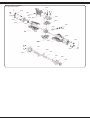
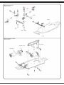
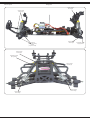
Montaje del diferencial delantero
Front gear assembly diagram

8
505074
505071
505085
505071
505073
079989
505384
505386
505385
505082
505387
505078
505087 505155
505091
079996
505054
505076
505388
505054
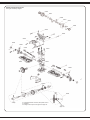
Montaje del diferencial trasero
Rear gear assembly diagram
Si el embrague deslizante se deslice, debe apretar la tuerca
de seguridad.
If the slipper clutch slips to much, tighten the slipper nut. Tuerca
Slipper nut

9
505029
505389
505077
505278
505390 (Ø 3,17mm)
EP 50 5480
505471
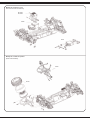
Montaje del servo set
Buer assembly
Montaje del motor o piñón
Motor assembly

10
505391
505392
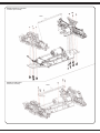
Montaje delanteros y traseros
Front/rear part assembly
Montaje de radio placa
Radio traxy assembly

11
505285
EP 081449
BL 081458
506119
505393
505394
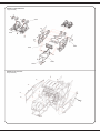
Montaje de recepción y servo
Servo and receiver box assembly
Montaje de la rueda de repuesto
Spare wheel assembly

12
505396
505395
505284 505397
505398
505399
505198
Montaje en jaula antivuelco
Cage assembly
Montaje de la carrocería
Body assembly

13
Montaje en jaula antivuelco
Cage assembly
Montaje de los neumáticos
Wheel assembly

14
4
A
A
BB
A
B
B
A
ES - Si ahora pones en marcha el vehículo, los LED están
activos.
GB - If you activate the model now, the LED´s are activ.
ES - Los LED no están activos en la entrega.
GB - The LED´s are not connected on delivery under certain
circumstances.
ES - El enchufe de los LED se encuentra en la caja del receptor.
GB - The LED connector is stored in the receiver box.
ES - Enchufe el conector del LED en el receptor en el canal 3
(CH3). La linea negra (negativo) sale a la derecha..
GB - Put the LED connector into the receiver to channel 3 (CH3).
The black line (minus) belongs to the right side.
ES - Abra la caja del receptor, quite el enchufe de los LED y el
receptor fuera.
GB - Open the receiver box and take out the LED connector
and the receiver.
LED-Stecker
LED-connector
Empfänger Kanal3
Receiver-CH3
ES - Coloque el receptor y los cables cuidadosamente en la caja
del receptor y ejecutar a través de las guías de cable hacia
afuera. Asegúrese de que los cables no apretar el gatillo.
GB - Put the receiver and the wiring back to the receiver box and
take care to install the wiring proberly. Dont squeeze the
wiring.
ES - Cierre la caja del receptor de nuevo con los 2 pasadores
de chaveta.
GB - Close again the receiver box with the two pins.
Barra de acoplamiento
corta su vez = positiva
ya su vez = negativa
Viajar
Spring travel
Turnbuckle
turn shorter = Toe-out
turn more = Toe-in Rear camber
Inclinación atras
mejor
rm mejor
rm
menos
soft
Camino muelle
Shock angle
Suspensión muelle
Spring tension
menos
soft
ES - El ajuste del tren de aterrizaje
Los consiguientes ajustes son posible:
Convergencia negativa / positiva
A Convergencia negativa:
La dirección es menos directa y el vehículo tiende
a sobrevirar.
B Convergencia positiva:
La dirección es directa y el vehículo tiende a
subviraje. Dirección directa no está precisa.
GB - Suspension Settings
The following settings are possible:
toe-in / toe-out
A Toe-in:
The responsiveness of the steering is less direct
and the vehicle tends to oversteer, but it has better
directional stability.
B Toe-out:
More direct steering response and understeer,
but has a worse directional stability.
ES - Inclinación Positivo/Negativo
delante y atras
A Negativo:
En el terreno es mejor, porque
los bordes de las ruedas se
levantan en la curva. Esto
permite una mayor velocidad
en la curva. Se recomienda
aprox. 1,5 grados negativo
delante y 0 grados atras como
un valor medio. Un alto ángulo
de inclinación negativo, puede
peorar la propiedades de
marcha.
B Positivo:
Con una inclinación positiva se
deberia evitar, porque el
vehículo tiene una peor
porpiedades de marcha.
GB - Negative camber / positive
camber front and rear
A Negative camber:
Better grip on terrain, as the
edge of the wheels stem into
the ground allowing higher
cornering speed. We
recommend approx. imately
1.5 degrees negative front and
an ave rage of 0 degree to the
rear. An excessive negative
camber angle can deteriorate
the ride quality.
B Positive camber:
A Positive camber should be
avoided in your vehicle due to
poorer ride quality.

15
Clip
front mounted =
higher caster
rear mounted =
lower caster
Spring tension
(less or more clip)
Shock angle
Track front
Caster
Spring tension
(less or more clip)
Shock angle
rear / top Rear camber
DE - Inclinación mayor/bajo delante
Bajo: Baja inclinación tiene un peor recta, pero
trae una dirección mejor en la entrada de
una curva.
Mayor: Inclinación mayor tiene una estabilidad
direccional mejor, pero puede tener una
peor dirección.
GB - Front caster high / low
Less caster: Less caster has a worse directional
stability, but provides a better steering on
corner entries.
High caster: A higher caster has a better directional
stability, but can result in worse corner
turn-in.
ES - Suspensión muelle duro/mórbido
delante y atras
Duro: Un comportamiento más
directo de la suspensión.
Mórbido: Un comportamiento menos
directo de la suspensión.
Ángulo de amortiguador mórbido/tenso
delante y atras
Mórbido: Dirección directa
Tenso: Menos dirección directa
Camino muelle mejor/menos
delante y atras
Menos: Menos altura sobre el suelo
y una bajo centro de
gravedad del vehículo.
Mejor: Major altura sobre el suelo y
major centro de gravedad del
vehículo.
GB - Spring tension
hard / soft front and rear
Harder: More direct response of
the suspension but
reduced grip.
Softer: Less direct response of
the chassis but more grip.
Damper angle soft / rm
front and rear
Soft: More direct steering
Firming: Less direct steering
Spring defelxion
more / less front and rear
Less: Less ground clearance
and lower center of
gravity.
More: More ground clearance
and higher center of
gravity.
Angelo de inclinación
Caster angle Clip
montado delante =
inclinación mayor
montado atras =
inclinación bajo
mejor
rm
menos
soft
Camino muelle
Shock angle
Suspensión muelle
Spring tension
DE - Einstellpunkte GB - Setting points
Suspensión muelle
(pinza menos o más)
Suspensión muelle
(pinza menos o más)
15
ES - Puntos de ajustes
Camino muelle
Inclinación atras Inclinación delante
Inclinación

16
Suspensión muelle
Spring tension
Camino muelle
Shock angle
Camino muelle
Shock angle
Camino muelle
Shock angle
Inclinación
(sólo tornillo interior)
Camber
(only inner screw)
Puntos de ajustes Setting points
Suspensión muelle
Spring tension
Camino muelle
Shock angle
Camino muelle
Shock angle
Camino muelle
Shock angle
Camino muelle
Shock angle

17
Version EP
Version EP
No. 505085
Rueda dendada A
Dierential bevel gear set
No. 505071
Rueda dendada B
Dierential bevel gear set
No. 505073
Corona de diferencias
Bevel gear
No. 505074
Caja diferencial
Dierential case set
No. 505075
Caja pinoneria
Gear box
No. 505077
Servo de ahorro clip
Buer steel column
Lista de repuestos Spare parts
No. 505078
Portada de transmisión
Shock mount
No. 505080
Engranaje
Ball head nut
No. 505081
Tornillo cabeza rotonda
Ball head screw
No. 505028 3 x 54 mm
Manguito de la dirección
Suspension arm shaft
No. 505054
3 x 35 | 3 x 26 | 3 x 22 mm
Manguito de la direcciónn
Suspension arm shaft set
No. 505382
Muñón del eje
Steering hub set
No. 505480
Motor eléctrico
E-Motor
No. 081449
CR40EP Lipo
Regulador Speed EP
Speed Controller
No. 505285
Box receptor
Receiver Box
No. 506119
Servo
Servo
No. 505155
Dif. delante+atras comp.
Di set front + rear compl.
No. 505284
Faro LED
Car light
No. 505040
Suporte brazo
Suspension xed rear/front
No. 505099
Brazo superior/delantero
Front upper suspension set
No. 505100
Brazo inferior/delantero
Front lower suspension set
No.505087
Brazo inferior/trasero
Rear lower suspension set
No. 505021
Servo conducion
Serve pulling rod set
No. 505029
Servo Set
Steering saver
No. 505082
Mangueta de zitel trasero
Rear shaft hub
No. 505385
Medir rueda
Hex joint set
No. 503581 M4
Tuerca c. borde autoblocantes
Nylon nut
No. 505469
Soporte del motor
Motor mount set
No. 505386
Proteccion pinoneria
Gear dustproof cover set
No. 505468
Corona conica 13D
Main gear 13T
No. 505387
Brazo superior trasero
Rear upper pulling rod set
No. 505389
Barra de acoplamiento
Steering rod connecting set
No. 505392
Bandeja radio
Radio tray
No. 505470
Amoretiguardor
Shock set front/rear
No. 505391
Cardano
Central shaft
No. 505471
Chasis
Chassis
No. 505091
Àrboles de transmisión
Drive shaft front/rear
No. 505472
Ròtula Central
Connecting cup
No. 505388
Torsion set
Slipper set
No. 505278
Soporte de la batería
Battery case
No. 505384
Soporte carroceria
Shock tower set rear/front
No. 505473
Eje delantero / trasero
Wheel axle rear/front
No. 505394
Neumatico + Llante
Tyres
No. 505393
Soporte de la rueda de
repuesto
Spare wheel mount
No. 505399
Arco jaula
Cage
No. 505398
Parachoques
Bumper
No. 505395
Dercoración
Cockpit
No. 505396
Imitación de casco
Helmet

18
Lista de repuestos Spare parts
No. 505198
Carroceria
Body
No. 505397
Parte lateral
Guard plate
No. 505475
Corona principal plastico
Main gear plastic
No. 505390
Piñón motor 14D
Motor Pinion gear 14T
No. 505045 Ø 7
E-clips
E-Clips
No. 505046 Ø 4
E-clips
E-Clips
No. 505047 Ø 2,5
E-clips
E-Clips
No. 079989 10 x 15 x 4
Cojinetes
Ball bearing
No. 079996 5 x 11 x 4
Cojinetes
Ball bearing
No. 070806 5 x 10 x 4
Cojinetes
Ball bearing
No. 505400 8 x 12 x 3,5
Cojinetes
Ball bearing
No. 505061 2 x 11
Pin
Pin
No. 505062 2 x 10
Pin
Pin
No. 059273
Clip de carroceria, 4 piezas
Body clip 4 pcs
No. 059274
Clip de carroceria de colores
Body-Clip colored
No. 505056 3 x 8
Tornillo
Flat head self tapping screw
No. 505075 M3 x 12
Tornillo
Cross screw
No. 505058 M3 x 8
Tornillo
Cross screw
No. 506145 M3x10
Tornillo
Flat head machine cros
screw
No. 059078 M3 x 8
Tornillo
Screw counter sunk
No. 506150 M4x4
Prisionero
Screw
No. 505060 M3x3
Prisionero
Screw
No. 506154
Emisora
Transmitter
No. 061171
CCX/SCX 2,4GHz
Receptor
Receiver
Piezas Tuning Tuning parts
No. 505270 Tam
230 V 12 V 350 mAh
Cargador
Charger
No. 505474 Alu
Hauptzahnrad
Main Gear
No. 505163
Cardan, delantero
Joint front / rear
No. 130156
Radiador del motor Alu
aktiv con ventilador
Cooling ns active with fan
No. 130157
Radiador del motor Alu aktiv
Vario con ventilador
Cooling ns alu active
variable with fan
No. 033215
Q7 Standard
Servo
Servo
No. 033216
High End MG 13/18
Servo
Servo
No. 061222
Compa X3 Evo 2,4 GHz
Emisora
Transmitter
No. 061201
CCX LiPo 2,4 GHz
Emisora
Transmitter
No. 061200
CCX Pro 2,4 GHz
Emisora
Transmitter
No. 505199
Decals
Decal
No. 141391 LiPo-Racing
7,4V 5000mAh 2N 30C
Batería Tamya cha
Battery Tamya plug
No. 413117
LiPo 20 2/3S
Cargador
Charger
No. 140141 Racing Pack
7,2 V 2000 mAh
Batería
Battery
No. 505271
Cargador NiMh
NiMh-Charger

19
Problemas y sus posibles soluciones
Después de encender, el motor no arranca y no se oye ninguna señal acústica.
1. La batería o la conexión de batería es incorrecta.
- Compruebe los cables, conectores y la batería en si.
Después del encendido, el motor no arranca, se emite una señal en un ciclo de 1 segundo.
1. La tensión de entrada no es correcta, es demasiado alta o demasiado baja.
- Compruebe el nivel de tensión de la batería.
Después del encendido, el motor no arranca, se envía una señal en un ciclo de 2 segundos
1. La señal de entrada se reconoce como incorrecta.
- Compruebe la emisora y el receptor, así como el cable de conexión del receptor del
regulador.
El motor gira en dirección contraria.
1. Las conexiónes del motor han sido cambiadas.
- Cambie dos cables de conexión entre motor y regulador.
El motor se para de forma repentina.
1. La señal de entrada no es correcta.
- Compruebe emisora, receptor y cables de servo.
2. El voltaje de la batería es demasiado bajo.
- Cargue su batería.
El motor funciona de forma irregular, va a tirones.
1. Existe alguna conexión suelta.
- Compruebe todas las conexiones con much o detalle.
2. La transmisión de radio sufre graves interferencias intermitentes.
- Apague el regulador y vuelva a encenderlo. Si todavía no consigue un funcionamiento
correcto, use su vehículo en otro sitio.
El modelo no responde
1. La batería o las baterías están vacías o defectuosas
- Cargue la bateria o sustituyala
2. Motor defectuosas
- Sustituya el motor
3. Cable Flojo o dañado
- Reconecte el cable o sustituya
4. El transmisor esta apagado o la conexion esta dañada
- Sustituya el transmisor o enciendalo
5. Receptor defectuoso
- Sustituya el receptor
6. El regulador de velocidad esta defectuoso
- Conecte apropiadamente o sustituya
El modelo reacciona sin ser controlado
1. El transmisor esta apagado o la conexion esta dañada
- Sustituya el transmisor o enciendalo
2. El control no esta calibrado o programado correctamente
- Recalibrar o reprogramar.
3. Receptor defectuoso
- Sustituya el receptor.
El motor comienza a correr al momento de encender, sin movimiento alguno.
1. Se instaló el Mecanismo de Seguridad de forma incorrecta
- Programar el Mecanismo de Seguridad en neutral
2. El acelerador ajustado al transmisor no está en neutral
- Poner el acelerador ajustado en neutral
El modelo solo se mueve hacia adelante.
1. El control no esta calibrado o programado correctamente
- Recalibrar o reprogramar.
Solamente Responde el volante
1. El control o regulador no esta calibrado o esta defectuoso
- Calibrar el reguladror o sustituirlo
El volante no responde.
1. El sistema de la dirección está defectuoso
- Sustituya el servo
2. El doble-tipo en el transmisor está instalado muy abajo
- Incrementar el doble tipo del transmisor
3. La palanca del volante esta muy sucia
- Limpiar y lubricar bien
Fuerte ruido de la traccion.
1. Engranaje principal, daños en el piñón o en el diferencial
- Partes dañadas deben de ser sustituidas
2. La red de engranaje no está correcta
- Re-ensamble red de engranaje
El regulador de velocidad se apaga al manejar.
1. Bajo voltaje de la bateria.
- Cargar la bateria.
2. Sobrecalentamiento
- Dejar que el regulador se enfrie.
Los ejes de transmision se caen
1. Ancho de la pista demasiado grande
- Reducción del ancho de la pista.
Troubleshooting
The motor will not rotate after switching on. No signal is present.
1. The battery pack or battery pack connectors are faulty.
- Check all of the connectors and the battery pack.
The motor will not turn after switching on. The ESC omits double signals with a 1 second
interval.
1. The input voltage is too high or too low.
- Check the battery pack voltage.
The motor will not turn after switching on. The ESC omits single signals with a 2 second
interval.
1. No or a poor receiver signal.
- Check both the transmitter and receiver as well as the ESC connecting cable.
The motor turns in the wrong direction.
1. The motor connecting cables are swapped
- Swap 2 of the ESC/motor connecting cables
The motor suddenly stops turning.
1. The battery voltage is too low.
- Charge the battery pack.
2. No signal.
- Check the transmitter, receiver and all of the cables only steering response
The motor stutters or runs irregularly.
1. One of the connectors is loose.
- Carefully check all of the connectors.
2. The receiver has intermediate interference.
- Switch the system o and then on. If the interference persists, operate the model in another
location.
Model does not respond
1. Battery or batteries empty or defective
- Charge battery or replace
2. Motor broken
- Replace motor
3. Loose or damaged cable
- Reconnect cable or replace
4. Transmitter turned o, lost or damaged binding
- Transmitter back on, bind or replace
5. Defective receiver
- Replace receiver
6. Speed controller is defective or connection issue
- Connect properly or replace
Model react uncontrolled
1. Transmitter turned o, lost or damaged binding
- Transmitter back on, bind or replace
2. Controller not calibrated or programmed incorrectly
- Recalibrate or reprogram
3. Defective receiver
- Replace receiver
Engine is running when you turn on inadvertently
1. Incorrectly set Failsafe
- Failsafe program to neutral
2. Throttle trim on the transmitter is not in neutral
- Throttle trim set to neutral
Model moves forward only
1. Controller not calibrated or programmed in correctly
- Recalibrate or reprogram
Only steering response
1. Regulator or Motor is defective or not Calibrated
- Calibrate speed controller or replace motor
Steering does not respond
1. Power steering defect
- Replace servo
2. Dual Rate on the transmitter set too low or to 0
- Dual rate increase
3. Very dirty steering lever or steering knuckle
- Clean and lubrcate well
Loud noise from the drive
1. Main gear, pinion or dierential damage
- Do not continue! aected part needs to be replaced
2. Incorrect gear mesh
- Reset gear mesh
Speed controller shuts o while driving
1. Low voltage cut-o, battery voltage too low
- Charging the battery
2. Overtemperature
- Let speed controller cool
Front drive shafts fall out
1. Too large track width
- Track width reduction

JAMARA e.K.
Inh. Manuel Natterer
Am Lauerbühl 5 - DE-88317 Aichstetten
Tel. +49 (0) 75 65/94 12-0 - Fax +49 (0) 75 65/94 12-23
[email protected] ● www.jamara.com
Service - Tel. +49 (0) 75 65/94 12-777
service@ jamara.com
DE - Servicehändler | GB - Service centre | FR - Revendeur de service | IT - Centro assistenza | ES - Servicio asistencia
CZ - Servisní centrum | SI - Servisni prodajalec | HR - Servisni centar | HU - Szerviz Kereskedő
DE - Reitter Modellbau Versand, Patricia Reitter, Degerfeldstrasse 11, DE-72461 Albstadt, Tel +49 (0) 7432 9802700, Fax +49 (0) 7432 2009594, [email protected], www.modellbauversand.de
EU - JAMARA e.K., Manuel Natterer, Am Lauerbühl 5, DE-88317 Aichstetten, Tel +49 (0) 7565 9412-0, Fax +49 (0) 7565 9412-23, [email protected], www.jamara.com
CH - Modellbau Zentral, Peter Hofer, Bresteneggstrasse 2, CH-6460 Altdorf, Tel +41 79 429 62 25, Mobil +41 41 870 02 13, [email protected], www.modellbau-zentral.ch
CZ - PenTec s.r.o., Distributor Jamara for Czech Republic and Slovakia, Veleslavínská 30/19, CZ-162 00 Praha 6, Tel +420 235 364 664, Mobil +420 739 075 380, servis@topdrony.cz, www.topdrony.cz
SI - Janus Trade D.O.O., Distributor Jamara for Slovenia, Koroška cesta 53c, SI-4000 Kranj, [email protected], www.janustrade.si
HR - Viva-net d.o.o., Distributor Jamara for Croatia, Ante Topic - Mimare 8, HR-10000 Zagreb-Susedgrad, [email protected], www.viva-net.hr
HU - Nettrade Kft., Distributor Jamara for Hungary, 1033 Budapest, Hévízi út 3/b, Tel +36 30 664 3835, [email protected]
Seguridad
• Lea atentamente las instrucciones y la seguridad antes de poner el modelo en
funcionamiento!
• Este dispositivo no debe ser utilizado por personas (incluidos niños) con discapacidad física,
habilidades sensoriales o mentales o la falta de experiencia y / o conoci mientos, porque son
responsables de su propia seguridad persona de supervisión o instrucción sobre cómo se utiliza
el dispositivo. O la persona que son supervisados o instruidos en cómo usar.
• El usuario es responsable en su totalidad para el correcto uso del modelo.
• Se prohíbe cualquier modicación de la estructura del modelo ya que anulará la garantía
inmediatamente.
• No deje nunca el modelo, el motor o las baterías expuestos a los rayos solares de manera
directa, colóquelos a la sombra.
• Prestar atención de que algunas partes del modelo pueden calentarse.
• Si el modelo, el motor o la batería se mojan, es necesario limpiar todo acuradamente en el seco
y limpio.
Funcionamiento
• Mantenga el modelo lejos de los niños, por lo que el modelo no es adecuado (vernota en edad).
• No haga funcionar su modelo en las proximidades de las es taciones de radio, líneas eléctricas,
cajas de transformadores, o como! Esto signi ca que puede la interferencia de radio principal
causa la pérda de control sobre el modelo!
• Evitar de conducir el modelo en sitios lleno de gente. Nunca conducir en la vìa pública.
• Mantenga las manos, cabello, la ropa lejos de los artículos de la rotación. Manten ga las piezas
des montadas.
• Utilice el modelo solo cuando las condiciones atmosféricas sean Buenas. No debería utilizar el
modelo si llueve, hay tormentas o se prevén malas condiciones atmosféricas.
• Antes, y después de cada marcha , inspeccione su modelo en busca de despefectos. Recuerde
que solo debe usar modelos en perfectas condiciones.
• Tenga en cuenta: El modelo está fabricado con plásticos y goma, siendo por lotanto altamente
inamable. Manténgalo lejos de cualquier llama o altas temperaturas.
• Mueva la palanca de gas siempre en la posición neutral.
Medidas de seguridad de las baterías
¡Debido a su densidad energética (hasta 150Kw/Kg.), los elementos no son inofensivos y necesitan
de unos cuidados mínimos! La empresa Jamara e. K., de manera explicita, declina cualquier
responsabilidad sobre los daños causado o derivados, por un manejo erróneo de las baterías Litio.
• Una utilización inapropiada conlleva riesgo de lesiones y/o incendios.
• Los elementos se dañarán por sobrecargas, corrientes muy altas, o descargas profundas.
• Proteja las baterías de golpes, dobleces, perforaciones, tensiones, etc.
• Bajo ningún concepto las abra o corte, no las arroje al fuego, manténgalas lejos del alcance de
los niños.
• Si están oxidadas o pierden electrolitos, manéjelas con mucho cuidado. Pueden estropear el
dispositivo o causarle lesiones.
• Nunca las cortocircuite, respetando en todo momento la polaridad.
• No permita que se calienten a más de 65ºC, aléjelas de partes calientes (P. Ej., la salida del
escape).
• Cárguelas antes de guardarlas (p.ej., en invierno= - ¡No las guarde descargada ni tampoco a
plena carga!
• Controle regularmente el nivel de carga durante los periodos de almacenamiento prolongados.
• El contenido de los elementos es dañino para la piel y los ojos.
• Si entra en contacto con la piel, lávese con agua y quítese la ropa usada.
• En contacto con los ojos, enjuáguese con abundante agua y visite al médico.
En caso de sobrecalentamiento de la batería, o cuando se ina, humea o empieza a quemar-
se, ya no debe tocarse de ningún modo. Por favor manténga una distan cia de seguridad y
ponga a disposición agentes para extinción adecuados (No hay peligro de explosión en el
agua, arena seca, extintores, mantas, agua salada).
Security instructions
• Read the instructions and security instructions carefully before using the model.
• This product is not intended for use by individuals (including children) with reduced physical,
sensory or mental capabilities or lack of experience and / or knowledge, unless they are
supervised by a person responsible for their safety and is able to give instructions about how the
product should be used. Children should be supervised to ensure that they do not play with the
product.
• The User is fully responsible for the correct use of the model.
• The model should not be changed in any way, doing so will invalidate the guarantee.
• Protect the model from strong sunlight, moisture and dust.
• Be aware that some parts of the model may get hot.
• If R/C unit, motor, or battery get wet, clean and dry thoroughly in a dry shaded area.
Operating
• Keep the model away from Children in case it is not appropriate to be used by a Child (see note
of age).
• Do not operate your model near radio stations, power lines, transformer boxes or similar facilities!
This can result in radio interference, causing loss of control over the model.
• Avoid driving the model to busy places. Never drive on public roads.
• Keep hands, hair and loose clothing away from rotating and heated parts.
• Drive the models only in good weather. Do not drive this models in wind, rain or thunder storms.
• Inspect the model before and after every drive for damage and loosing screws and plug
connections. Please ensure that only an intact model is used.
• Your model is made from such materials as plastic and rubber and as such is inammable. Keep
it away from any open ame, or high temperatures.
• Always ensure that the throttle stick is in the low position before you switch on.
Safety precausions for battery
Because of the high power compactivity (up to 150 Wh/kg) the cells are quite dangerous and need
special care! The company Jamara excludes explicitly, all types of liability for damages, that can
occure when using the Lithium-Polymer-
Cells indequate.
• When using the battery incorrect there is a risk of getting re or acid-injuries.
• Overcharging, too high power, or discharging at low level destroys the cell.
• Protect from mechanical stress (squeezing, pushing, bending, drilling).
• Never open or cut batteries, do not throw into re, keep away from children.
• Handle damaged or leaking battery with care. Injuries or damages to the product can occure.
• Under no circumstance short-circuit the device and always watch out for correct polarity.
• Protect batteries from heat above 65 °C , mount away from hot objects (for example exhaust pipe).
• Before storing batteries (for example in the winter) charge the battery. Do not store in fully charged
or in non charged state!
• The contents of the cell is harmfull for skin and eye.
• If the content comes into contact with skin, clean with plenty of water and take o moisted clothes.
• If the content comes into contact with the eyes, clean with plenty of water and consult a doctor.
If the cell overheats, swells, burns or smoke is coming from it, do not touch it under any cir-
cumstances. Keep away in a safe distance and prepare adequate extinguishing agents such
(No water explosion, well dry sand, re extinguishers, re blanket, salt water).
Notas sobre el reciclado
Baterías y acumuladores no deben desecharse en la basura doméstica, pero se deben de-
sechar de forma separada. Usted está obligado, a realizar la eliminación profesional de las
baterías viejas (recogida selectiva). Es posible devolver las baterías después de su uso de
forma gratuita en las actividades comerciales. Dado que las baterías contienen sustancias
que causan irritación, pueden causar alergias o son altamente reactivos, la recogida selecti-
va y el reciclaje son importantes para el ambiente y su salud. Si las baterías, por debajo del
“bidón con ruedas borrado” están marcados con un símbolo químico, Hg, Cd o Pb, signica
que contiene más de un 0,0005 % de Mercurio (Hg), más de 0,002 % de Cadmio (Cd) o más
de 0,004 % de Plomo (Pb).
Notas sobre el reciclado
Aparatos eléctricos no pueden desecharse en la basura doméstica, pero se deben desechar
de forma separada. Usted está obligado, a quitar las baterías y llevar los aparatos eléctricos
viejos en los puntos de recogida comunales. En caso de que hay datos personales en el
aparato eléctrico se deben remover de usted mismo..
Disposal restrictions
Batteries and accumulators must not be disposed of in domestic waste. You are obliged to
dispose of batteries (seperate collection) appropriately. After use you can return batteries free
of charge to the retail store. As batteries contain substances that can be irritant, can cause
allergy and are highly reactive, separate collections and proper recycling is important to the
environment and to your health. If the batteries are marked with a chemical symbol Hg, Cd or
Pb below the crossed-out waste bin on wheels it refers to that more than 0.0005% of mercury
(Hg), more than 0.002% of cadmium (Cd) or more than 0.004% Lead (Pb) is included.
Disposal restrictions
Electrical appliances must not be disposed of in domestic waste and must be disposed of se-
parately. You are obliged to take out the batteries, if possible, and to dispose of the electrical
equipment at the communal collection points. Should personal data be stored on the electrical
appliance you must remove them by yourself.
Salvo error o modicación técnica. Copyright JAMARA e. K. 2022
Prohibida su reproducción o distribución, por cualquier medio, salvo consentimiento expreso de JAMARA e.K.
All rights reserved. Copyright JAMARA e.K. 2022
Copying or reproduction in whole or part, only with the expressed permission of JAMARA e.K.
-
 1
1
-
 2
2
-
 3
3
-
 4
4
-
 5
5
-
 6
6
-
 7
7
-
 8
8
-
 9
9
-
 10
10
-
 11
11
-
 12
12
-
 13
13
-
 14
14
-
 15
15
-
 16
16
-
 17
17
-
 18
18
-
 19
19
-
 20
20


Jamara 053290 EP Dakar 24 GHz Instrucciones de operación
- Categoría
- Juguetes a control remoto
- Tipo
- Instrucciones de operación
en otros idiomas
Artículos relacionados
Otros documentos
-
HPI Racing Maverick Strada Manual de usuario
-
DF-models df-models 3168 XL Fighter Brushless Toy Car Manual de usuario
-
-
Maverick Maverick Phantom Manual de usuario
-
-
Traxxas Blast RC Speed Boat Manual de usuario