Boston CS 270 Manual de usuario
- Categoría
- Amplificador de instrumentos musicales
- Tipo
- Manual de usuario
Este manual también es adecuado para

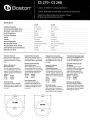
Specifications
Frequency Response
C5270
65Hz-20kHz
C5280
50Hz-20kHz
10
- 100 watts
90dB
5,000Hz
80hms
8" (203mm)
%"(20mm)
12%2"(312mm)
1
O'l'8"
(276mm) diameter
4%2"(110mm)
-------
NCBR8
NCBR6
4,000Hz
10
- 90 watts
-------------------------------
90dB
80hms
6Y2"
(165mm)
----------------------------------
%"(20mm)
---
10
5
116"
(262mm)
------~-----,---------------
8'l8"(225mm)
diameter
4"(100mm)
Recommended
Amplifier
Power
Tweeter
Sensitivity
1
watt
(2.83v)-at 1m
Nominal
Impedance
Crossover Frequency
Woofer
External
Dimensions
Mounting
Hole
Cutout
Mounting
depth
(from
surface)
Optional
New
Construction
Bracket
Optional
Cover Plate
Cover6R Cover8R
--------------------------------~-
Support
NCBR6
NCBR8
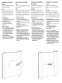
Required Clearances
Behind the mounting surface,
there must
be
l-inch
(25mm)
clearance around the mounting
hole.
Optional Brackets
for
New Construction
For
new construction installa-
tions, we offer new construction
brackets.The
NCB
brackets act
as
aperfect gUide when cutting the
wallboard.
Model Bracket
CS
270
NCBR6
CS
280
NCBR8
To
Remove Grille
If
you need
to
remove the grille,
gently lift it
out
at the edges.
Use
asharp pointed instrumentsuch
as
an
awl.
Espacios libres necesarios
Detras de
la
superficie de mon-
taje debe haber
2S
mm
libres al-
rededor del espacio del montaje.
Soportes opcionalespara
construccion nueva
Para
instalaciones
en
construc-
ciones nuevas ofrecemos sopo-
rtes opcionales.
Los
soportes
NCB
sirven perfectamente de guias
para
el
corte de carton-yeso.
Modelo
So
porte
CS
270
NCBR6
CS280
NCBR8
Para
quitar
la rejilla
Si
necesita quitar
la
rejilla,
levantela con cuidado por
los
extremos. Utilice una herramien-
ta afilada y puntiaguda, como
un punzon.
Degagements necessaires
Derriere
la
surface de montage,
un degagement de
25
mm
doit
etre present autour du trou de
montage.
Supportsde fixation
facultatifs
pour
constructions neuves
Pour
les
installations dans
des
constructions neuves, nous of-
frons des supports speciaux.
Ces
supports sont ideaux pour servir
de guides lors de
la
decoupe des
murs.
Modele
CS
270
CS
280
Retrait dela
grille
Pour retirer
la
grille, soulevez-Ia
delicatement
en
la
tenant par
les
bords. Utilisez un instrument
pointu affile, tel qu'un point;on.
Erforderliche Mindestabstande
Hinterder Montageflache
muss
urn das Montageloch ein Spiel
von
25
mm vorhanden' sein.
OptionaleHalterungenfUr
Neubauten
Fur
die Montage in neuen
.Gebauden bieten wir besondere
Halterungen. Die NCB-Halter-
ungen sind eine idea
Ie
Rich-
t1inie,
wenn Gipskartonplatten
geschnitten werden.
Modell Halterung
CS
270
NCBR6
CS
280
NCBR8
Entfernen des Ziergitters
Wenn
das
Ziergitter entfernt
werden
muss,
heben
Sie
dieses
an
den Kanten vorsichtig heraus.
Verwenden
Sie
dazu ein spitzes
Werkzeug wie eine
Ah
~~~~
10
7
/8"
275mm
//~S~8~~'\
--
-
---
/'
"
/
"
/
(5270
"\
I
\
/
\
I
10
7
/8
)
{
\
\ 276mm
/
I
8
7
/8'
I
\
225mm
/
\
/
\
/
\
/
"-
"
/
"-
/
"
/'
"
/'
---
--
.......
---
.......

Installation Instructions
WARNING
Always
turn
off
the
amplifieror
receiver
when
connecting
speakers
oranyother
components
to
the
system.
NOTE
This
manual
assumes
the
installer
possesses
skill
in
the
proper
use
of
hand
andpower
tools,
knowledge
of
local
building and
fire
codes,
anda familiarity
with
the
environmentbehind
the
wall
or
ceiling
in
which
the
speakers
will
be
installed.
ToolsYou'll Need
1.
A
utility
knife,
jig
saw,
or
other
tool
for cutting
the
required hole in
the
mounting
surface.
2.
A
#2
Phillips screwdriver.
3.
Awire cutter
or
stripperfor
preparing
the
speaker wires.
4.
A pencil.
Retrofit Installations
1.
Mark
the
outline
of
the
installation
hole using
the
supplied template.
Make a small hole at
the
center
of
the
speaker location. Inserta
long,
bent
piece
of
wire and
rotate
to
confirm
that
there
are no obstructions behind
the
chosen location.
2.
Cut
the
installation hole.
3.
Run
the
wire from
the
amplifier
location
to
the
cutout. Allow for
an
extra
foot
of
wire at
the
cutout.
Instrucciones de
montaje
AVISO
Apague
siempre
el
amplificador0
el
receptor
alconectar
altavoces
0 cualquieratro compo-
nente
al
sistema.
NOTA
En
este
manual
se
presupone
que
el
instalador
posee
habilidad
en
el
manejo
de
herramientas
manuales
y
eli?ctricas,
conocimiento
sobre
los
cMigos
vigentes
de
construcci6n
localy
nor-
mas
sobre
incendios
y
que
estd
familiarizado
con
el
entomo
tras
el
muro 0
techo
en
los
que
se
instalardn
los
alta
voces.
Herramientas necesarias
1.
Una navaja multiusos, una sierra·
caladora u otra herramienta para cortar
el
agujero adecuado en
la
superficie de
montaje.
2.
Un
destornillador de estrella 0 cruz del
numero
2.
3.
Un
cortador de alambre 0 un
pelacables para preparar el cableado
de los altavoces.
4.
Un
lapiz.
Instalaciones para
el
montaje
trasero
1.
Marque
el
contorno
del agujero con
la
plantilla suministrada. Haga
un
pequeno agujero en el centro de
la
ubicacion del altavoz. Meta un alambre
curvado y dele vueltas para asegurarse
de que no hay obstaculos traseros en
la
posicion elegida.
2.
Corte
el
agujero para
la
instalacion.
3.
Tienda
el
cable desde el amplificador
hasta
el
final. Corte a
30
cm mas de
10
necesario.
Instructions d'installation
AVERTISSEMENT
Oebranchez
toujours
I'amplificateur
ou
Ie
recepteur
avant
de
connecter
les
enceintes
ou
toutautre
compoSQnt
du
systeme.
REMARQUE
Ce
manuel
suppose
que
/'installateur
saitutiliser
les
outils amain etamoteur
necessaires
a/'installation, qu'iIconnait
la
reglementation
en
vigueur
sur
la
construc-
tion et
/'incendie,
etqu'ilsait exactement
ce
qui
se
trouve
derriere
les
murs
ou
les
pia
fonds
sur
lesquels
les
enceintes
seront
installees.
Outils necessaires
1. Un couteau, une scie II decouper
ou
tout
autre
outil
capable dedecouper
I'orifice necessaire dans
la
surface de
montage.
2.
Un tournevis cruciforme No.2.
3. Une pince coupante
ou
II
denuder
pour
preparer les fils des enceintes.
4.
Un crayon
noir
Installations ameliorees
1.
Tracez Ie contour
de
I'orifice
d'installation en utilisant
Ie
gabarit
fourni. Faites un
petit
trou au centre
de I'endroit
OU
sera
placee I'enceinte.
Inserez-y un grand morceau de cable
replie,
et
faites
tourner
celui-ci afin
de
vous assurer qu'il n'existe aucun
obstacle derriere I'endroit choisi.
2.
Decoupez I'orifice d'installation.
3.
Amenez
Ie
cable
de
I'ampli
II
I'orifice
que vous venez de decouper, en
prevoyant
30
cm
de
cable
supplementaire.
Installationsan-weisungen
ACHTUNG
Den
Verstarker
oder
Empfanger
immer
abstellen,
wenn
Lautsprecher
oder
andere
Komponenten
an
das
System
angeschlossen
werden.
HINWEIS
Oieses
Handbuch
setzt
voraus,
dass
der
Installateur
im
Umgang
mit
Hand-
und
Elektrowerkzeugen
versiert
ist,
die
6rtlichen
Bau-
und
Brandschurzvorschriften
kennt
und
weds,
wo
und
welche
Leitungen
in
der
Wand
bzw.
hinter
der
Wandverkleidung
verlaufen,
in
der
die
Lautsprecher
montierr
werden
sollen.
Benotigte
Werkzeuge
1.
Ein
Exaktormesser, eine Stichsage oder
anderes Werkzeug zum Ausschneiden
des
notwendigen
Lochs aus
der
Mon-
tageflache.
2.
Einen Kreuzschlitz-Schraubendreher,
GroBe
2.
3.
Eine Drahtzange
oder
einen
DrahtstripperzurVorbereitung
der
Lautsprecherkabel.
4.
Einen Bleistift.
Einbau
in
eine
fertige
Flache
1.
Den Umriss des Installationslochs
mit
der
mitgelieferten Maske anzeichnen.
In
der
Mitte
der
auszuschneidenden
Flache ein kleines Loch erzeugen.
Ein
langes Stuck gebogenen Drahts in
das Loch einschieben, urn zu prufen,
dass
hinter
der
gewahlten Stelle keine
Hindernisse vorhanden sind.
2.
Das
Montageloch schneiden.
3.
Das
Kabel
vom
Verstarker zum eben
erzeugten Ausschnitt verlegen.
An
der
Ausschnittstelle etwa
30
cm extra
Kabellange vorsehen.

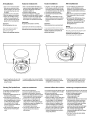
All Installations
1.
Strip V,-inch (13mm)
of
insulation
from
the
wire, and
twist
the
wire
strands together.The speakerjack
will accept either bare wire
up
to
14-gauge.
2.
Connect
the
wire
to
the
speaker.
3.
Slide
the
speaker
into
the
cutout.
4.
TIghten
the
4 Phillips
mounting
screws.The
mounting
arms
will
pivot
into
position and clamp
the
speaker
to
the
mounting
surface.
Important:
Do notovertighten the
screws.
If
you
wish
to
paintyour
speakers
or
grilles,
itshould
be
done
prior
to
installation
of
the
grille.
Please
see thepainting instructions.
Todas
las
instalaciones
1.
Pele
13
mm
del aislante del cable y re-
tuerza
el
extremo para agrupar los hilos.
EI
conector del altavoz acepta
tanto
alambre
de
calibre 14.
2.
Conecte el cable
al
altavoz.
3.
Introduzca el altavoz en el agujero.
4.
Apriete los tornillos
de
estrella 0 cruz
de
montaje.
Los
brazos
de
montaje giraran
hasta
su
posici6n y mantendran el al-
tavoz sujeto a
la
superficie del montaje.
Importante:
No
apriete demasiado
los
tomil/os.
5i
quiere
pintar
los
altavoces
0
las
rejiilas
de-
berG
hacerlo
antes
de
10
instalaci6n
de
10
rejilla.
Consulte
las
instrucciones
para
pintarlos.
Toutes installations
1.
Denudez
13
mm
de
cable,
et
torsadez
les fils soupies ensemble.
La
fiche de
I'enceinte accepte les cables denudes
d'un
diametre maximum de calibre
14.
2.
Connectez Ie cable a I'enceinte.
3.lntroduisez I'enceinte dans I'orifice
decoupe.
4.
Revissez
les
vis de fixation.
Les
sup-
ports de fixation
pivotent
en position
et
fixent I'enceinte sur la surface de
fixation.
Important:
Ne
resserrez
pas
les
vis
excessivement.
5i
vous
voulez
peindre
les
enceintes
ou
les
grilles,
faites-Ie
avant!'installation
des
grilles.
Veuillez
consulter
les
instructions de
peinture qui suivent.
Aile Installationen
1.
13
mm
Isolierung
vom
Kabel
entm-
anteln, und die Drahtlitzen zusam-
mendrehen. DerLautsprecheranschluss
nimmt
entwederblanken Draht bis
zu
AWG14.
2.
Kabel an den Lautsprecher anschlieBen.
3.
Den Lautsprecher in den Ausschnitt
schieben.
4.
Die Kreuzschlitz-Befestigungs-schrau-
ben festziehen. Die Montagearme
schwenken in die Einbaustellung und
klemmen den Lautsprecheran der
Montageflachefest.
Wichtig:
Die
Schrauben nichtzu
fest
anziehen.
Wenn
die
Lautsprecher
oder
Ziergitter lackiert
werden
soilen,
muss
dies
vor
der
Installation
des
Ziergitters
geschehen
(siehe
Anweisungen
zum
Lackieren).
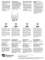
5.
Insert
the
grille
into
the
slots in
the
baffle by
gently
applying pressure
along
the
edge.
Painting
The
Speaker
Frame
The speakers may be painted before
or
afterthey are installed.They are
already primed.
1.
Insert
the
supplied
paint
mask
into
the
frame
of
the
speaker.
2.
Paint
the
frame.
If
you are using
spray paint,
apply
two
light
coats. If
you are applying paint
with
a brush
or
roller,
thin
the
paintand apply
two
very
light
coats.This helps
prevent excessive paint
buildup
or
"runs"
on
the
frame.
3.
After
the
paint has dried, use
the
finger pulls
to
remove
the
paint
mask.
S.
Inserte
la
rejilla en
las
ranuras del bafle
presionando ligeramenteen losextremos.
Todas
las
instalaciones
Pintura
el
marco del altavoz
Los
altavoces puedenpintarse antes
o despues
de
la
instalaci6n.Vienen de
fabrica con can base para pintura
0 primer.
1.
Inserte
la
plantilla (mascara) para pintar
suministrada en el marco del altavoz.
2.
Pinte el marco.
Si
utiliza pinturaen
spray, aplique dos capas Iigeras.
Si
utiliza pincel 0 rodillo, diluya
la
pintura
y aplique dos capas
muy
delgadas. Esto
evitara
el
exceso de pintura y
el
"corrimiento"
de
la misma.
3.
Una vez
seca
la
pintura, tire
de
los
lugares previstos en
la
mascara
para retirarla.
S.
Inserez
la
grille dans les fentes
du
haut-parleura membraneen appuy-
ant legerement sur
ses
bords.
Peinture
Coffrets
des
enceintes
Les
enceintes peuvent etre peintes avant
ou apres leur installation. Elles
ont
deja
re~u
une couche defond.
1.
Inserez
Ie
masque a peinture fourni
dans
Ie
coffret
de
I'enceinte.
2.
Peignez Ie coffret.
Si
vous utilisez
de
la
peinture
au
pistolet, appliquez deux
couches legeres.
Si
vous appliquez
la
peinture avec un pinceau
ou
un
rouleau, diluez-Ia
et
appliquez deux
couches tres lege
res.
Vous eviterez
ainsi une accumulation excessive de
peinture
ou
des coulees sur Ie coffret.
3.
Une fois
que
la
peinture est seche,
utilisez les languettes
pour
retirer
Ie
masque de peinture.
5.
Fugen
Sie
das Ziergitter in die Schlitze
in
der
Schallwand ein, indem
Sie
ent-
lang der Kante vorsichtig andrucken.
Lackierung
Lautsprecherrahmen
Die Lautsprecher k6nnen voroder nach
der
Installation lackiert werden.
Sie
sind bereits
mit
einerGrundierung versehen.
1.
Legen
Sie
die mitgelieferte
Lackierungsmaske in den
Lautsprecherrahmen.
2.
Lackieren
Sie
den Rahmen. Wenn
Sie
den
Lack aufspruhen, mussen zwei dunne
Schichten aufgetragen werden.Wenn
Lack
mit
einem Pinsel oder einerWalze
aus
der
Dose aufgetragen wird,
verdunnen
Sie
erst den Lack und tragen
dann zwei ganz dunneSchichten auf.
Dies verhindert ubermaBig dicke
Lackansammlungen oderLack-"Tranen"
auf
dem Rahmen.
3.
Nach
dem
Trocknen des
Lacks
ziehen
Sie
die Lackierungsmaske an den
Fingerlaschen
abo

Painting
the
Speaker Grille
1.
Carefully remove
the
cloth
from
the inside
of
the
grille. Set
it
aside
in aclean location for later
reinstallation.
2.
Paint
the
grille.
If
you are using
spray paint, apply
two
light
coats.
If
you are applying
paint
with
a brush
or
roller,
thin
the
paint and apply
two
very
light
coats.This helps
prevent paint
from
filling
the
holes
on thegrille.
3.
After
the
paint
is
dry, reinstall the
cloth and grille logo.
For
EU
Customers
Only
This symbol found on
the
product
indicates
that
the
product
mus
not
be disposed
of
with
household waste. Instead,
it
may
be
placed
in a separate collection facility forelectronic
waste
or
returned
to
a
retailer
when
purchasing similar
product.
The producer paid
to
recycle this product.
Doing thiscontributes
to
reuse
and
recycling.
minimizes adverse effects on
the
environ-
ment
and
human
health
and avoids
any
nnes
for
incorrectdisposal.
If
Service
Seems
Necessary
First, contact the dealer
from
whom
you purchased the product.
Or contact us via e-mail at:
USA
and Canada:
Japan: [email protected]
Asia/Pacific countries:
We
will
promptly
advise you
of
what
action
to
take. If
it
is
necessary
to
return your speakers
to
the
factory,
please ship
it
prepaid. After
it
has
been repaired,
we
will return
it
freight prepaid in the United States
and Canada,
La
rejilla delaltavoz
1.
Quitecuidadosamente
la
tela del
interior
de
la
rejilla. Dejela aparteen
sitio
limpio
para
su
posterior instalacion.
2.
Pinte la rejilla.
Si
utiliza pinturaen spray,
apliquedos capas ligeras.
Si
utiliza
pincel
0
un
rodillo, diluya
la
pintura y
aplique dos capas
muy
delgadas.
Esto
evitara el exceso
de
pintura y
el "corrimiento"
de
la
misma.
3.
Cuando
la
pintura este
seca,
vue
Iva
a
colocar
la
tela y
ellogo.
S610
para c1ientes
de
la
UE
Este simbolo
que
aparece
en
el
produeto
indica
que
este
no
debe
ser
eliminado
con
la
basuradomestica.
En
vez
de
esto,
debe
colocarse en
un
punta
de
recogida separada
para desechos electr6nicos 0 devuelto a un
detallista al
comprar
un
producto
si-milar.
El
fabricante ha
pagado
para reciclar este
producto.
Haciendo esto
contribuye
a
reuti-
Iizar y reciclar,
minimiza
los efectos adversos
sobreel
medioambiente
y la salud
humana
y evita
cualquier
multa
por
una
eliminacion
incorrecta.
Si
cree que necesita
asistencia tecnica
Prlmero, pongase en contacto con el dis-
tribuidor
al
cual
ha
comprado el producto.
opongase en contacto con nosotros
por
medio
de
un
correo electronico:
Estados
Unidos
y Canada:
Japon: [email protected]
Asia/paises
del
Pacifi co:
Le
indicaremos
de
inmediato
que
accion
tomar.
Si
es
necesario devolver
un
altavoz
a
la
fabrica,
Ie
rogamos
que
10
envie
con franqueo prepago. Despues de
la
reparacion,
10
devolveremos con costas
de
transporte pagados solo en Estados
Unidos y Canada.
PeintureGrille des enceintes
1.
Otez
Ie
tissu
de
j'interieur
de
la
grille.
Mettez-Ie
de
cote dans un endroit
propre.
2.
Peignez
la
grille.
Si
vous utilisez de
la
peinture au pistolet, appliquezdeux
couches legeres.
Si
vous appliquez
la
peintureavec
un
pinceau ou un
rouleau, diluez-Ia etappliquez deux
couches tres lege
res.
Vous eviterez
ainsi
que
la
peinture ne remplisse les
trous
de
la
grille.
3.
Une fois
que
la
peintureest seche,
reinstallez
Ie
tissu
et
Ie
logo
de
la
grille.
Pour les clients
de
I'UE
uniquement
Ce
symbole
sur Ie
produit
indique
que
Ie
produit
ne
doit
pas etre
jete
avec les dechets
domestiques.
II
doit
plutot
etre placedans
une
installation
de
collecte separee destinee
aux dechets
electroniques
ou
remis a
un
detaillant
lorsque
vous achetez
un
produit
semblable.
Le
fabricant a-paye
pour
recycler
ce
produit,
ce
qui
contribue
areutiliser
et
recycler
et
ce
qui
minimise
les effets nefastes
sur
I'environnement
et
la sante humaine,
tout
en
evitant
des
amendes
encourues
en
cas
d'elimination
incorrecte.
Demande
de
service
apres-vente
Veuillez contacter en premierlieu
Ie
rev-
endeuraupres
duquel
vous avez achete
ce
produit.
Ou veuillez nous contacter par
e-mail:
Etats-Unis
et
Canada:
Japon : [email protected]
Pays
de
l'Asie/Pacifi
que:
Nous vous informerons rapidement
des mesures
aprendre.
Si
vous devez
retourner
aI'usine votre haut-parleur
veuillez I'expedierdans
un
colis prepaye.
Apres
la
reparation,
II
vous
sera
retourne
en fret prepaye aux Etats-Unis
et
au
Canada.
Lackierung Lautsprecher-
Ziergitter
1.
Entfernen
Sie
vorsichtig g}lsTuch von
der Innenseite des Ziergitters. Legen
Sie
es
zur spateren Installation an einem
sauberen
Ort
abo
2.
Lackieren
Sie
das Ziergitter.Wenn
Sie
den
Lack aufsprUhen, mUssen zwei dUnne
Schichten aufgetragen werden. Wenn
Lack
mit
einem Pinsel odereinerWalze
aus
der
Dose aufgetragen wird,
verdUnnen
Sie
erst den Lack und tragen
dann zwei ganzdUnne Schichten auf.
Damit
wird
verhindert, dass sich die
Locher des Ziergitters
mit
Lack fUlien.
3.
Nachdem derLack trocken ist,
installieren
Sie
dasTuch
und
das
Ziergitter-Logo.
NurfOr
Kunden in
der
EU
Dieses
auf
dem
Produkt angebrachte Symbol
weist
darauf
hin, dass das
Produkt
nicht
mit
dem
HausmOli
entsorgt
werden darf.
Es
muss
bei einer Sammelstelle
fOr
Elektronikschrolt
abgegeben
oder
dem
Handler
Obergeben
werden,
wenn
ein
ahnliches
Produkt
erwor-
ben
wird. DerHersteller hat
fOr
das Recycling
dieses Produktes bezahlt. Dies
tragt
zur
Wiederverwertung
und
zurn Recycling
bei
minimiert
schadliche
Auswirkungen
auf
die
Umwelt
und
die menschliche Gesundheit
und
vermeidet
Geldbussen fUr unsach-
gemasse Entsorgung.
Falls ein Kundendienst
notwendig
scheint
Nehmen
Sie
zunachst Kontakt
mit
dem
Handlerauf, bei
dem
Sie
das Produkt
gekauft haben.
Oderkontaktieren
Sie
uns per E-Mail unter:
USA
und
Kanada: [email protected]
Japan: [email protected]
Asien/Pazifi sche Region:
Wir werden Ihnen
umgehend
mitteilen,
wie
Sie
weiter vorgehen sollten.
Falls
es
notwendig
sein sollte, Lautsprecher den
HerstellerzurUckzusenden,
so
versenden
Sie
diese
bitte
frei. Nach
der
Reparatur
werden
wir
Siein den
USA
und
in Kanada ebenfalls frei zurUcksenden.
300 Jubilee Drive, Peabody,
MA
01960
USA
bostonacoustics.com
© 2008 Boston Acoustics, Inc. Boston, Boston Acoustics,
and
the
Boston Acoustics
logo
are registered trademarks
and
the
BfA ellipse
symbol is a trademad<
of
Boston Acoustics, Inc.
Dolby
Digital,
and
Dolby
Pro Logic are registered trademarks
of
Dolby
Laboratories.
DTS
is
a registered trademarks
of
DTS,
Inc. Specificationsare subject
to
change
without
notice. 142-003535-1


l
...
Boston
acoustics'
AnN:
PRODUCT REGISTRATION
BOSTON ACOUSTICS INC
300 JUBILEE DR
PEABODY MA 01960-4030
111"""111,1",11"11""1"111,,,,,11,11,,,11,,,11,"1,,,11
Postage
Required
Post Office will
notdeliver
without
proper
postage.

~
Boston
Acoustics·
Product Registration
for
U.S.
and Canada purchases only.
Boston
Thank
you
for
purchasing
a
Boston
Acoustics product
Your
feedback
wm
help
us
to
conUnue
providing
acoustic
6-
consumers
with
!he
best
possible products and service. Data provIded Is the confidential
property
of
Boston
AcoustIcs,
Inc. and Is
not
distributed
or
sold
to
third
partltlS.
Please print below, or register your new product online at: bostonacoustics,comlprodreg
First
Name
_
last
Name
_
StreetAddress _
Apl.._-----
City _
State _
ZIP
_
e·mall
_
Ph008
_
Age
Group:
UndElf
20
201029
30 to 39 40 to 49 50 to 59
60
to 69
70
to
79
80
and
over
Marttal
Status;
Single
_
Marrled_
Mate
Female
Educatloo:
High School _
Some
College _ Associate/Jr. College Degree _ 4-Year College Degree _ Graduate
School_
What type ofBoston AcotJstics product did you ptJrt:hase? Home StereolThealBf
In-WaIUln-eelling _
MulUmedlalPC
Date
of
Purchase
,
,,
_
Model
Name
serial
#
1I;;;;;;;;;';~~.~.;;
••
;;_;;;;~~h;;;.;;;;;'
••
;,
;;,;,";'"
------
HO'N
did
you
hear aboutlhts
product?
Store Name City State _
Boston Acoustics advertisement Store salesperson _ Store advertisement Magazlne review _
Store
display_
Online review _ Tntde show _
PC
manufacturer _
Friendlfamity_
Q1he,----------------------------
What other brand(s) and model(s)
did
yoo
consider
when
maklng lhls purchase?
Bnlnd(s) _
Model(a) _
Thank you
for
completing this form.
If
you have any tec:hnlc.l question.
or
.t.
Interested In other Boston Acoustlca products, vlalt ua on the
Web
at
boatonacouatlca,com.
or
call (978) 538-5000.
m007
&a.lon
AeouIIlclI,
Ir'lt.
All
RIghts
R~
142.oo1eol-3
Transcripción de documentos
Specifications C5270 C5280 Frequency Response 65Hz-20kHz 50Hz-20kHz Recommended Amplifier Power 10 - 90 watts 10 - 100 watts ------------------------------- Sensitivity 1 watt (2.83v)-at 1m 90dB 90dB Nominal Impedance 80hms 80hms Crossover Frequency 4,000Hz 5,000Hz Woofer 6Y2" (165mm) Tweeter %"(20mm) 8" (203mm) ---------------------------------- %"(20mm) --- 116" (262mm) External Dimensions 105 Mounting Hole Cutout 8'l8"(225mm) diameter 1O'l'8" (276mm) diameter 4%2"(110mm) ------NCBR8 12%2"(312mm) ------~-----,--------------- Mounting depth (from surface) 4"(100mm) Optional New Construction Bracket NCBR6 Optional Cover Plate Cover6R Cover8R --------------------------------~- Soportes opcionales para construccion nueva Para instalaciones en construcciones nuevas ofrecemos soportes opcionales. Los soportes NCB sirven perfectamente de guias para el corte de carton-yeso. Modelo Soporte CS 270 NCBR6 CS280 NCBR8 Optional Brackets for New Construction For new construction installations, we offer new construction brackets. The NCB brackets act as a perfect gUide when cutting the wallboard. Model Bracket CS 270 NCBR6 CS 280 NCBR8 ~~~~ //~S~8~~'\ 107 /8 276mm / \ "- / " " --- -- ....... / /' Supports de fixation facultatifs pour constructions neuves Pour les installations dans des constructions neuves, nous offrons des supports speciaux. Ces supports sont ideaux pour servir de guides lors de la decoupe des murs. Modele Support CS 270 NCBR6 CS 280 NCBR8 Para quitar la rejilla Si necesita quitar la rejilla, levantela con cuidado por los extremos. Utilice una herramienta afilada y puntiaguda, como un punzon. To Remove Grille If you need to remove the grille, gently lift it out at the edges. Use a sharp pointed instrument such as an awl. I I \ \ Degagements necessaires Derriere la surface de montage, un degagement de 25 mm doit etre present autour du trou de montage. Espacios libres necesarios Detras de la superficie de montaje debe haber 2S mm libres alrededor del espacio del montaje. Required Clearances Behind the mounting surface, there must be l-inch (25mm) clearance around the mounting hole. Retrait de la grille Pour retirer la grille, soulevez-Ia delicatement en la tenant par les bords. Utilisez un instrument pointu affile, tel qu'un point;on. 10 7/8" 275mm /' / / \ ) { / I -- - --- " (5270 / " "\ \ \ I 8 7 /8' 225mm \ / \ / "- / " --- ....... /' Erforderliche Mindestabstande Hinter der Montageflache muss urn das Montageloch ein Spiel von 25 mm vorhanden' sein. Optionale Halterungen fUr Neubauten Fur die Montage in neuen .Gebauden bieten wir besondere Halterungen. Die NCB-Halterungen sind eine ideaIe Richt1inie, wenn Gipskartonplatten geschnitten werden. Modell Halterung CS 270 NCBR6 CS 280 NCBR8 Entfernen des Ziergitters Wenn das Ziergitter entfernt werden muss, heben Sie dieses an den Kanten vorsichtig heraus. Verwenden Sie dazu ein spitzes Werkzeug wie eine Ah Installation Instructions Instrucciones de montaje Instructions d'installation Installationsan-weisungen WARNING Always turn off the amplifier or receiver when connecting speakers or any other components to the system. AVISO Apague siempre el amplificador 0 el receptor al conectar altavoces 0 cualquier atro componente al sistema. AVERTISSEMENT Oebranchez toujours I'amplificateur ou Ie recepteur avant de connecter les enceintes ou tout autre compoSQnt du systeme. ACHTUNG Den Verstarker oder Empfanger immer abstellen, wenn Lautsprecher oder andere Komponenten an das System angeschlossen werden. NOTE This manual assumes the installer possesses skill in the proper use ofhand and power tools, knowledge oflocal building and fire codes, and a familiarity with the environment behind the wall or ceiling in which the speakers will be installed. NOTA En este manual se presupone que el instalador posee habilidad en el manejo de herramientas manuales y eli?ctricas, conocimiento sobre los cMigos vigentes de construcci6n local y normas sobre incendios y que estd familiarizado con el entomo tras el muro 0 techo en los que se instalardn los altavoces. REMARQUE Ce manuel suppose que /'installateur sait utiliser les outils main et moteur necessaires /'installation, qu'iI connait la reglementation en vigueur sur la construction et /'incendie, et qu'il sait exactement ce qui se trouve derriere les murs ou les piafonds sur lesquels les enceintes seront installees. Tools You'll Need 1. A utility knife, jig saw, or other tool for cutting the required hole in the mounting surface. 2. A #2 Phillips screwdriver. 3. A wire cutter or stripper for preparing the speaker wires. 4. A pencil. Herramientas necesarias 1. Una navaja multiusos, una sierra· caladora u otra herramienta para cortar el agujero adecuado en la superficie de montaje. 2. Un destornillador de estrella 0 cruz del numero 2. 3. Un cortador de alambre 0 un pelacables para preparar el cableado de los altavoces. 4. Un lapiz. Outils necessaires 1. Un couteau, une scie II decouper ou tout autre outil capable de decouper I'orifice necessaire dans la surface de montage. 2. Un tournevis cruciforme No.2. 3. Une pince coupante ou II denuder pour preparer les fils des enceintes. 4. Un crayon noir Retrofit Installations 1. Mark the outline of the installation hole using the supplied template. Make a small hole at the center of the speaker location. Insert a long, bent piece of wire and rotate to confirm that there are no obstructions behind the chosen location. 2. Cut the installation hole. 3. Run the wire from the amplifier location to the cutout. Allow for an extra foot of wire at the cutout. Instalaciones para el montaje trasero 1. Marque el contorno del agujero con la plantilla suministrada. Haga un pequeno agujero en el centro de la ubicacion del altavoz. Meta un alambre curvado y dele vueltas para asegurarse de que no hay obstaculos traseros en la posicion elegida. 2. Corte el agujero para la instalacion. 3. Tienda el cable desde el amplificador hasta el final. Corte a 30 cm mas de 10 necesario. a a a Installations ameliorees 1. Tracez Ie contour de I'orifice d'installation en utilisant Ie gabarit fourni. Faites un petit trou au centre de I'endroit OU sera placee I'enceinte. Inserez-y un grand morceau de cable replie, et faites tourner celui-ci afin de vous assurer qu'il n'existe aucun obstacle derriere I'endroit choisi. 2. Decoupez I'orifice d'installation. 3. Amenez Ie cable de I'ampli II I'orifice que vous venez de decouper, en prevoyant 30 cm de cable supplementaire. HINWEIS Oieses Handbuch setzt voraus, dass der Installateur im Umgang mit Hand- und Elektrowerkzeugen versiert ist, die 6rtlichen Bau- und Brandschurzvorschriften kennt und weds, wo und welche Leitungen in der Wand bzw. hinter der Wandverkleidung verlaufen, in der die Lautsprecher montierr werden sollen. Benotigte Werkzeuge 1. Ein Exaktormesser, eine Stichsage oder anderes Werkzeug zum Ausschneiden des notwendigen Lochs aus der Montageflache. 2. Einen Kreuzschlitz-Schraubendreher, GroBe 2. 3. Eine Drahtzange oder einen Drahtstripper zur Vorbereitung der Lautsprecherkabel. 4. Einen Bleistift. Einbau in eine fertige Flache 1. Den Umriss des Installationslochs mit der mitgelieferten Maske anzeichnen. In der Mitte der auszuschneidenden Flache ein kleines Loch erzeugen. Ein langes Stuck gebogenen Drahts in das Loch einschieben, urn zu prufen, dass hinter der gewahlten Stelle keine Hindernisse vorhanden sind. 2. Das Montageloch schneiden. 3. Das Kabel vom Verstarker zum eben erzeugten Ausschnitt verlegen. An der Ausschnittstelle etwa 30 cm extra Kabellange vorsehen. All Installations Todas las instalaciones Toutes installations Aile Installationen 1. Strip V,-inch (13mm) of insulation from the wire, and twist the wire strands together. The speaker jack will accept either bare wire up to 14-gauge. 2. Connect the wire to the speaker. 3. Slide the speaker into the cutout. 4. TIghten the 4 Phillips mounting screws. The mounting arms will pivot into position and clamp the speaker to the mounting surface. 1. Pele 13 mm del aislante del cable y retuerza el extremo para agrupar los hilos. EI conector del altavoz acepta tanto alambre de calibre 14. 2. Conecte el cable al altavoz. 3. Introduzca el altavoz en el agujero. 4. Apriete los tornillos de estrella 0 cruz de montaje. Los brazos de montaje giraran hasta su posici6n y mantendran el altavoz sujeto a la superficie del montaje. 1. Denudez 13 mm de cable, et torsadez les fils sou pies ensemble. La fiche de I'enceinte accepte les cables denudes d'un diametre maximum de calibre 14. 2. Connectez Ie cable a I'enceinte. 3.lntroduisez I'enceinte dans I'orifice decoupe. 4. Revissez les vis de fixation. Les supports de fixation pivotent en position et fixent I'enceinte sur la surface de fixation. 1. 13 mm Isolierung vom Kabel entmanteln, und die Drahtlitzen zusammendrehen. DerLautsprecheranschluss nimmt entweder blanken Draht bis zu AWG14. 2. Kabel an den Lautsprecher anschlieBen. 3. Den Lautsprecher in den Ausschnitt schieben. 4. Die Kreuzschlitz-Befestigungs-schrauben festziehen. Die Montagearme schwenken in die Einbaustellung und klemmen den Lautsprecher an der Montageflache fest. Important: Do not overtighten the screws. Importante: No apriete demasiado los tomil/os. Important: Ne resserrez pas les vis excessivement. 5i quiere pintar los altavoces 0 las rejiilas deIfyou wish to paint your speakers or grilles, it should be done prior to installation of the grille. berG hacerlo antes de 10 instalaci6n de 10 rejilla. 5i vous voulez peindre les enceintes ou les Consulte las instrucciones para pintarlos. grilles, faites-Ie avant !'installation des grilles. Veuillez consulter les instructions de peinture qui suivent. Please see the painting instructions. Wichtig: Die Schrauben nicht zu fest anziehen. Wenn die Lautsprecher oder Ziergitter lackiert werden soilen, muss dies vor der Installation des Ziergitters geschehen (siehe Anweisungen zum Lackieren). 5. Insert the grille into the slots in the baffle by gently applying pressure along the edge. S. Inserte la rejilla en las ranuras del bafle presionando ligeramente en los extremos. S. Inserez la grille dans les fentes du haut-parleur a membrane en appuyant legerement sur ses bords. 5. Fugen Sie das Ziergitter in die Schlitze in der Schallwand ein, indem Sie entlang der Kante vorsichtig andrucken. Painting The Speaker Frame Todas las instalaciones Peinture Coffrets des enceintes Lackierung Lautsprecherrahmen The speakers may be painted before or after they are installed. They are already primed. 1. Insert the supplied paint mask into the frame of the speaker. 2. Paint the frame. If you are using spray paint, apply two light coats. If you are applying paint with a brush or roller, thin the paint and apply two very light coats. This helps prevent excessive paint buildup or "runs" on the frame. 3. After the paint has dried, use the finger pulls to remove the paint mask. Pintura el marco del altavoz Los altavoces pueden pintarse antes o despues de la instalaci6n. Vienen de fabrica con can base para pintura 0 primer. 1. Inserte la plantilla (mascara) para pintar suministrada en el marco del altavoz. 2. Pinte el marco. Si utiliza pintura en spray, aplique dos capas Iigeras. Si utiliza pincel 0 rodillo, diluya la pintura y aplique dos capas muy delgadas. Esto evitara el exceso de pintura y el "corrimiento" de la misma. 3. Una vez seca la pintura, tire de los lugares previstos en la mascara para retirarla. Les enceintes peuvent etre peintes avant ou apres leur installation. Elles ont deja re~u une couche de fond. 1. Inserez Ie masque a peinture fourni dans Ie coffret de I'enceinte. 2. Peignez Ie coffret. Si vous utilisez de la peinture au pistolet, appliquez deux couches legeres. Si vous appliquez la peinture avec un pinceau ou un rouleau, diluez-Ia et appliquez deux couches tres legeres. Vous eviterez ainsi une accumulation excessive de peinture ou des coulees sur Ie coffret. 3. Une fois que la peinture est seche, utilisez les languettes pour retirer Ie masque de peinture. Die Lautsprecher k6nnen vor oder nach der Installation lackiert werden. Sie sind bereits mit einer Grundierung versehen. 1. Legen Sie die mitgelieferte Lackierungsmaske in den Lautsprecherrahmen. 2. Lackieren Sie den Rahmen. Wenn Sie den Lack aufspruhen, mussen zwei dunne Schichten aufgetragen werden. Wenn Lack mit einem Pinsel oder einer Walze aus der Dose aufgetragen wird, verdunnen Sie erst den Lack und tragen dann zwei ganz dunne Schichten auf. Dies verhindert ubermaBig dicke Lackansammlungen oder Lack-"Tranen" auf dem Rahmen. 3. Nach dem Trocknen des Lacks ziehen Sie die Lackierungsmaske an den Fingerlaschen abo Painting the Speaker Grille La rejilla del altavoz Peinture Grille des enceintes 1. Carefully remove the cloth from the inside of the grille. Set it aside in a clean location for later reinstallation. 2. Paint the grille. If you are using spray paint, apply two light coats. If you are applying paint with a brush or roller, thin the paint and apply two very light coats. This helps prevent paint from filling the holes on the grille. 3. After the paint is dry, reinstall the cloth and grille logo. 1. Quite cuidadosamente la tela del interior de la rejilla. Dejela aparte en sitio limpio para su posterior instalacion. 2. Pinte la rejilla. Si utiliza pintura en spray, aplique dos capas ligeras. Si utiliza pincel 0 un rodillo, diluya la pintura y aplique dos capas muy delgadas. Esto evitara el exceso de pintura y el "corrimiento" de la misma. 3. Cuando la pintura este seca, vueIva a colocar la tela y ellogo. 1. Otez Ie tissu de j'interieur de la grille. Mettez-Ie de cote dans un endroit propre. 2. Peignez la grille. Si vous utilisez de la peinture au pistolet, appliquez deux couches legeres. Si vous appliquez la peinture avec un pinceau ou un rouleau, diluez-Ia et appliquez deux couches tres legeres. Vous eviterez ainsi que la peinture ne remplisse les trous de la grille. 3. Une fois que la peinture est seche, reinstallez Ie tissu et Ie logo de la grille. Lackierung LautsprecherZiergitter 1. Entfernen Sie vorsichtig g}ls Tuch von der Innenseite des Ziergitters. Legen Sie es zur spateren Installation an einem sauberen Ort abo 2. Lackieren Sie das Ziergitter. Wenn Sie den Lack aufsprUhen, mUssen zwei dUnne Schichten aufgetragen werden. Wenn Lack mit einem Pinsel oder einer Walze aus der Dose aufgetragen wird, verdUnnen Sie erst den Lack und tragen dann zwei ganz dUnne Schichten auf. Damit wird verhindert, dass sich die Locher des Ziergitters mit Lack fUlien. 3. Nachdem der Lack trocken ist, installieren Sie das Tuch und das Ziergitter-Logo. For EU Customers Only S610 para c1ientes de la UE Pour les clients de I'UE uniquement NurfOr Kunden in der EU This symbol found on the product indicates Este simbolo que aparece en el produeto Ce symbole sur Ie produit indique que Ie Dieses auf dem Produkt angebrachte Symbol that the product mus not be disposed of with indica que este no debe ser eliminado con produit ne doit pas etre jete avec les dechets weist darauf hin, dass das Produkt nicht mit household waste. Instead, it may be placed la basura domestica. En vez de esto, debe domestiques. II doit plutot etre place dans dem HausmOli entsorgt werden darf. Es muss in a separate collection facility for electronic colocarse en un punta de recogida separada une installation de collecte separee destinee waste or returned to a para desechos electr6nicos 0 devuelto a un aux dechets electroniques ou remis a un retailer when purchasing similar product. detallista al comprar un producto si-milar. detaillant lorsque vous achetez un produit The producer paid to recycle this product. El fabricante ha pagado para reciclar este semblable. Le fabricant a-paye pour recycler Doing this contributes to reuse and recycling. producto. Haciendo esto contribuye a reuti- ce produit, ce qui contribue areutiliser et bei einer Sammelstelle fOr Elektronikschrolt abgegeben oder dem Handler Obergeben werden, wenn ein ahnliches Produkt erwor- ben wird. Der Hersteller hat fOr das Recycling dieses Produktes bezahlt. Dies tragt zur Wiederverwertung und zurn Recycling bei minimizes adverse effects on the environ- Iizar y reciclar, minimiza los efectos adversos recycler et ce qui minimise les effets nefastes ment and human health and avoids any nnes sobre el medioambiente y la salud humana sur I'environnement et la sante humaine, tout minimiert schadliche Auswirkungen auf die for incorrect disposal. y evita cualquier multa por una eliminacion en evitant des amendes encourues en cas Umwelt und die menschliche Gesundheit incorrecta. d'elimination incorrecte. und vermeidet Geldbussen fUr unsachgemasse Entsorgung. If Service Seems Necessary First, contact the dealer from whom you purchased the product. Or contact us via e-mail at: USA and Canada: [email protected] Japan: [email protected] Asia/Pacific countries: [email protected] We will promptly advise you of what action to take. If it is necessary to return your speakers to the factory, please ship it prepaid. After it has been repaired, we will return it freight prepaid in the United States and Canada, Si cree que necesita asistencia tecnica Demande de service apres-vente Falls ein Kundendienst notwendig scheint Prlmero, pongase en contacto con el distribuidor al cual ha com prado el producto. Veuillez contacter en premier lieu Ie revendeur aupres duquel vous avez achete ce produit. Nehmen Sie zunachst Kontakt mit dem Handler auf, bei dem Sie das Produkt gekauft haben. medio de un correo electronico: Estados Unidos y Canada: [email protected] Japon: [email protected] Asia/paises del Pacifi co: [email protected] Ou veuillez nous contacter par e-mail: Etats-Unis et Canada: [email protected] Japon : [email protected] Pays de l'Asie/Pacifi que: [email protected] Oder kontaktieren Sie uns per E-Mail unter: USA und Kanada: [email protected] Japan: [email protected] Asien/Pazifi sche Region: [email protected] Le indicaremos de inmediato que accion tomar. Si es necesario devolver un altavoz a la fabrica, Ie rogamos que 10 envie con franqueo prepago. Despues de la reparacion, 10 devolveremos con costas de transporte pagados solo en Estados Unidos y Canada. Nous vous informerons rapidement des mesures prendre. Si vous devez retourner I'usine votre haut-parleur veuillez I'expedier dans un colis prepaye. Apres la reparation, II vous sera retourne en fret prepaye aux Etats-Unis et au Canada. o pongase en contacto con nosotros por a a Wir werden Ihnen umgehend mitteilen, wie Sie weiter vorgehen sollten. Falls es notwendig sein sollte, Lautsprecher den Hersteller zurUckzusenden, so versenden Sie diese bitte frei. Nach der Reparatur werden wir Sie in den USA und in Kanada ebenfalls frei zurUcksenden. 300 Jubilee Drive, Peabody, MA 01960 USA bostonacoustics.com © 2008 Boston Acoustics, Inc. Boston, Boston Acoustics, and the Boston Acoustics logo are registered trademarks and the BfA ellipse symbol is a trademad< of Boston Acoustics, Inc. Dolby Digital, and Dolby Pro Logic are registered trademarks of Dolby Laboratories. DTS is a registered trademarks of DTS, Inc. Specifications are subject to change without notice. 142-003535-1 l... Boston acoustics' Postage Required Post Office will not deliver without proper postage. AnN: PRODUCT REGISTRATION BOSTON ACOUSTICS INC 300 JUBILEE DR PEABODY MA 01960-4030 111"""111,1",11"11""1"111,,,,,11,11,,,11,,,11,"1,,,11 ~ Boston Boston Acoustics· Product Registration for U.S. and Canada purchases only. Thank you for purchasing a Boston Acoustics product Your feedback wm help us to conUnue providing consumers with !he best possible products and service. Data provIded Is the confidential property of acoustic 6- Boston AcoustIcs, Inc. and Is not distributed or sold to third partltlS. Please print below, or register your new product online at: bostonacoustics,comlprodreg _ last Name First Name _ StreetAddress _ City _ State _ e·mall _ 201029 Age Group: UndElf 20 Marttal Status; Single _ Educatloo: High School _ 30 to 39 Marrled_ Some College _ , ,, _ Model ZIP _ Ph008 60 to 69 50 to 59 Mate What type of Boston AcotJstics product did you ptJrt:hase? Date of Purchase 40 to 49 Apl.._----- 70 to 79 4-Year College Degree _ In-WaIUln-eelling _ Home StereolThealBf MulUmedlalPC City Boston Acoustics advertisement Online review _ Graduate School_ serial # 1I;;;;;;;;;';~~.~.;;•;•;_;;;;~~h;;;.;;;;;' ••;,;;,;,";'"- - - - - - Name Store display_ 80 and over Female Associate/Jr. College Degree _ Store Name HO'N did you hear aboutlhts product? _ Store salesperson _ Tntde show _ State Store advertisement PC manufacturer _ _ Magazlne review _ Friendlfamity_ Q1he,---------------------------What other brand(s) and model(s) did yoo consider when maklng lhls purchase? Bnlnd(s) _ Model(a) Thank you for completing this form. If you have any tec:hnlc.l question. or Web at boatonacouatlca,com. or call (978) 538-5000. m007 &a.lon AeouIIlclI, Ir'lt. All RIghts R~ .t. _ Interested In other Boston Acoustlca products, vlalt ua on the 142.oo1eol-3-
 1
1
-
 2
2
-
 3
3
-
 4
4
-
 5
5
-
 6
6
-
 7
7
-
 8
8


Boston CS 270 Manual de usuario
- Categoría
- Amplificador de instrumentos musicales
- Tipo
- Manual de usuario
- Este manual también es adecuado para
en otros idiomas
- français: Boston CS 270 Manuel utilisateur
- English: Boston CS 270 User manual
- Deutsch: Boston CS 270 Benutzerhandbuch
Artículos relacionados
Otros documentos
-
Boston Acoustics CS 270 Manual de usuario
-
Boston Acoustics CS 275 Manual de usuario
-
-
-
Boston Acoustics HSI 460T2 Manual de usuario
-
-